universal joints - apex fasteners · pdf file · 2015-06-01universal joints to...
TRANSCRIPT

UniversalJoints
Apex®
SP
-140
0-E
N 0
307
15M

Table of Contents
ISO 9001 . . . . . . . . . . . . . . . . . . . . 1
Overview . . . . . . . . . . . . . . . . . . . . 2–7
Apex 300 Series Universal Joints . . . 8–9
Apex 400 Series Universal Joints . . .10–11
Apex Double Universal Joints . . . . . .12–13
Apex Quick-Change/Telescopic Universal Joints . . . . . . . . . . . . . . . .14–15
MS20270 Universal Joints . . . . . . . . 16
MS20271 Universal Joints . . . . . . . . 17
MS Series Deflection Curves . . . . . . 18
Needle Bearing Universal Joints . . . . 19
Instructions to Calculate Correct Joint Size . . . . . . . . . . . . . . 20
Custom Application Sheet . . . . . . . . 21
Training . . . . . . . . . . . . . . . . . . . . .22–23
Formulas & Conversion Tables . . . . . 24
Website Information . . . . . . . . . . . . . 25
300 SeriesPages 8-9 400 Series
Pages 10-11
Double UJ’sPages 12-13
Quick-Change/TelescopicPages 14-15
Military StandardMS20271
Page 17 Needle Bearing UJ’sPage 19
Military StandardMS20270
Page 16
Cooper Power Tools also offers a full line of universal joint products for pipeline cleaners. Contact Customer Service for more information or download the Airetools product catalog atwww.cooperpowertools.com.

ISO 9001Quality System Certified
1
Cooper Power Tools Division has attained ISO 9001 Quality SystemCertification for seven of our facilities. *Our Dayton facility,manufacturing site of Apex Universal Joints, also has AS9100 QualitySystem Certification. The driving force behind the implementation ofthe Quality System is the commitment “to provide our customers withthe best value delivered by offering only products and servicesthat meet or exceed their expectations”.
Lexington, South Carolina
Springfield, Ohio*Dayton, Ohio Hicksville, Ohio
Braunschweig, Germany Westhausen, Germany Ozoir-la-Ferrière, France

Apex has been supplying universal joints formilitary and commercial applications since1933. Over these 70+ years we haveprovided engineered solutions for thousandsof demanding applications worldwide. TodayApex is recognized as the “Less downtime,more Lifetime” leader in pin and cubeuniversal joint designs and applications. Ourprimary markets are:
Government/Military ApplicationsApex meets the demanding requirementsmilitary applications such as gun systems,remote valve control, Unmanned AerialVehicles (UAV), thrust vector controlsystems, and fan drive universal joints.
Apex Universal Joints Overview
LessDowntime,MoreLifetime.
2

AerospaceCommercial, military, business jets, andprivate aircraft all utilize Apex universaljoints. Typical uses include flap/slatactuation, “hinges” for cargo doors andwindows, mechanical linkages forsteering, trim control and door latchingmechanisms. Apex double universaljoints have even been used to replacegear boxes. These high strength-to-weight ratiouniversal joints have excellent torsional freeplay(i.e., backlash) characteristicssuited to this environment.
Off-highway/ConstructionEquipmentApplications include steeringcolumns, a variety ofmechanical linkages andpower take offs. Also includedare custom designs forspecialty equipment (e.g. firetrucks.)
3

Apex Universal Joints Overview
4
Performance RacingOur MS series of universal joints have become thestandard by which all other universal joints aremeasured. The same aerospace designconsiderations are applicable in this competitivemarket. Primary uses are for steering, shift linkages,and chassis adjustment applications.
Industrial Power TransmissionThis represents the most diverse area ofapplications. Some typical uses are steel levelingequipment, links to conveyor systems, pump drivesystems, multiple spindle drill heads, bowling alleypin setters, canning equipment, centerless grinders,bottling machines, industrial sewing machines,control linkages, mixing equipment, packagingmachinery, and industrial scales. This list representsonly a fraction of the applications where Apexuniversal joints are used. Our “quick-change”universal joints are extremely popular in this area.They eliminate precision alignment requirements andallow for quick repair of critical machinery andassembly/conveyor lines.
Apex universal joints consistently deliver performancein process industries where continuous operation isthe norm and equipment availability/uptime is critical.
Whatever your application, you can depend on Apexuniversal joints to provide rigidity and exceptionallyhigh strength-to-weight ratios with less deflection,superior fatigue resistance and high overloadcapacity. Add to this Apex’s wide selection ofelastomeric covers that seal lubrication in and protectthe universal joint from harsh operating environments(e.g., dirt, water, abrasive slurry, etc.), and you haveunsurpassed reliability for your application. All ofthese features can be incorporated into single,double, telescopic, or quick-change universal joints.We specialize in make-to-order products engineeredto optimize your application and reduce operatingcosts. Apex is the Performance Authority for pin-and-cube universal joints.

5
Apex Offers A Variety ofSolutions For Your Standardor Custom ApplicationIf your application calls for somethingother than our standard 300 or 400series universal joints, Apex can provideit for you. Our engineers are ready tosolve your application problems. Someof the options available are:
■ Universal Joint Configurations:
In addition to the standard plain bearingdesign, there is also a “Press Fit”
design which improves fatigue life in reverse loadingapplications. For higher RPM’s, we offer a needlebearing line.
■ Materials:
Alloy steels (4140, 4150, 4340), Austenitic stainlesssteel (303, 304, 316, Nitronic 60), Martensiticstainless steel (416, 440C, 13-8, 17-4, 15-5),carbon steel (1020, 8620) and specialty steels (suchas Stressproof and S-2 Modified).
■ Bearings:
Apex utilizes plain, rolling element and polymer
bearings in its designs. Selecting the right bearingmaximizes the performance the universal joint,minimizes/eliminates maintenance, and increases thelife of the universal joint.
■ Heat Treatment:
Apex proprietary heat treat, selective throughhardening, induction hardening, and case hardening.
■ Surface Treatment:
Light oil, cadmium (electrolytic and vacuum),electrolytic zinc, nickel (electrolytic and electroless),black oxide, phosphate (manganese and zinc), solidfilm lubricant, and a variety of paint solutions.
■ Cover Materials:
Silicone, Nitrile, EPDM, Viton, Neoprene,FDA approved food polymer, vinyl,Silicon/Dacron, Fluoro-Silicon/Nomex.
■ Cover Styles:
Bulbous, flat, and convoluted.
■ Lubricants:
High pressure gear oil, “natural” grease, syntheticgrease, synthetic grease with additives (improves
“dry start” characteristics), non-outgassing grease, food grade grease,graphite powder, and solid film lubricant.
■ Geometry:
Square, Hex, Threaded, splines (involuteor straight-sided), gears, split collar withlug bolt, keyways, precision diameters(.0002”), gears, whistle-notch, andquick-release. Where applicable, theseare available in male or female.
Additionally, multiple features can becombined on the same hub. Apexengineers utilize these options daily todesign the product right for your needs.From extreme loading (including seismic)to harsh environments (-80˚ to 600˚ F),Apex is your Total Solution Source.

Apex Universal Joints Overview
8
The Apex Total Solution Designed IntoEvery Universal JointThe illustration below highlights many of the commondesign features that have made Apex the MarketLeader in providing “less downtime, morelifetime” for some of the most demandingapplications. At the heart of this success isengineering excellence that created and continues torefine this design to meet the ever increasingchallenges of new applications. To furthercompliment this, add Apex’s manufacturingcapabilities and its proprietary heat-treat processes.The result is a “balanced” design that provides thehighest strength-to-weight ratio pin and cubeuniversal joint available. It is not uncommon for Apexto outperform the competition by at least 30% instrength for equivalent size products.
When you bring your applications to Apex, you willbe supported by a technical staff that has the in-house capability to perform Finite Element Analysis(FEA), 3-D Solid Modeling, Metallurgical analysis,non-destructive testing, functional testing, and
Earform GeometryDesigned, developed andtested for “balanced design”load carrying capability.
Cross PinStrengthens the assemblyduring intermittent overloador severe bending conditions
CubeHeat treated alloy steel,precision machined tominimize backlash, sideplay, and endplay of theassembly. Geometric controlassures smooth operation.
Apex design engineers utilize 3-D solid models and finite element analysis (FEA) to develop and evaluate different design options.
Drive pins (main pin and bushings)• Heat treated alloy steel, precision ground
for minimum backlash and long service life. • Designed for balanced strength with earform.
InterchangeabilityApex offers a wide variety of hubconfigurations (bore, keyway, hex,spline, square, threads) to meet yourrequirements.
Performance Features:■ Efficient operation up to 35°standard (higher operatingangles available)
■ Designed-in overloadcapacity for greater reliability.(Temporary torsionaloverloads up to 80% and axialoverloads up to 150% of therated ultimate capacity canoccur without harmfulbinding.)
■ Proprietary heat treat ofalloy steel maximizes“toughness”
■ Available with covers thatseal in lubrication and greatlyimprove service life.

9
prototype production.
The most useful tool, however, is the knowledgegained from providing application solutions for over60 years. Use the application sheet at the back ofthis catalog to find out how Apex universal joints canimprove the performance of your application.
Short delivery times required for replacement parts orproduct development samples can be produced inthe “Short Run Cell”.
This cell has all of the manufacturing capability toproduce almost any configuration universal joint in anexpedited manner. A single machinist takesownership of the job and is responsible for it fromproduction to final assembly. Please ask about thisservice if you have an expedited need for a smallquantity of parts.
Apex has extensive in-house testing and validation capabilities.

Single Universal Joints300 Series
8
300 Series
■ Single universal joint with operating angles up to 35 degrees
■ Full range of sizes from 3/8” to 2”■ Ultimate static strength up to
26,040 lbs-in■ Available with or without
lubrication covers■ Standard cover supplied is Neoprene
or Nitrile, others available■ Select from solid hubs, bored hubs
and bores with keyways■ Hubs do not need to be the same
on both ends■ Field/customer machinable alloy steel■ Plating available upon request
Performance specifications for standard products3/8” 276 31 500 2,224 156 18 55 6 4 0.45 1.001/2” 504 57 1,400 6,228 300 34 110 12 4 0.45 0.805/8” 960 108 2,500 11,121 576 65 190 21 4 0.45 0.643/4” 1,680 190 4,500 20,017 1,008 114 340 38 4 0.45 0.537/8” 2,520 285 7,000 31,138 1,512 171 500 56 8 0.90 0.461” 4,500 508 12,500 55,603 2,700 305 900 102 8 0.90 0.401-1/4” 7,200 813 19,700 87,630 4,320 488 1,450 164 8 0.90 0.321-1/2” 12,000 1,356 24,000 106,757 7,200 813 2,400 271 8 0.90 0.271-3/4” 15,600 1,763 29,000 128,998 9,360 1,058 3,100 350 8 0.90 0.232” 26,040 2,942 39,000 173,481 15,600 1,763 5,200 588 8 0.90 0.20
In addition to these standard configurations, different end configurations can be combined. Please call for additional information and pricing.Metric and special sizes available upon request. Please call or fax form at the back of catalog.
Minimum Ultimate Maximum Maximum Peak Torque Torsional PlayStatic Torsional Ultimate Momentary Stall (for shock load or
Size Strength Axial Strength (overload) Torque reversal conditions) Test TorqueMax
Lbs-in N-m Lbs N Lbs-in N-m Lbs-in N-m Lbs-in N-m Degrees

Single Universal Joints300 Series
9
Solid Hubs300-6-S 0.375 9.5 1.750 44.4 0.093 0.042300-8-S 0.500 12.7 1.875 47.6 0.144 0.065300-10-S 0.625 15.9 2.188 55.6 0.233 0.106300-12-S 0.750 19.1 2.500 63.5 0.356 0.162300-14-S 0.875 22.2 3.000 76.2 0.508 0.231300-16-S 1.000 25.4 3.375 85.7 0.758 0.345300-20-S 1.250 31.8 3.750 95.2 1.247 0.567300-24-S 1.500 38.1 4.500 114.3 2.156 0.980300-28-S 1.750 44.4 5.000 127.0 3.125 1.420300-32-S 2.000 50.8 5.500 139.7 4.500 2.045
A B Weight ofPart Number +.001, -.006 +/-.031 Solid-hub(Uncovered) Outside Diameter Overall Length Covered Assembly
in mm in mm Lbs kg
Bored Hubs300-6-4 0.375 9.5 0.250 6.3300-8-4 0.500 12.7 0.250 6.4300-8-6 0.500 12.7 0.375 9.5300-10-6 0.625 15.9 0.375 9.5300-10-7 0.625 15.9 0.438 11.1300-10-8 0.625 15.9 0.500 12.7300-12-8 0.750 19.1 0.500 12.7300-12-10 0.750 19.1 0.625 15.9300-14-8 0.938 23.8 0.500 12.7300-14-12 0.938 23.8 0.750 19.1300-16-10 0.938 23.8 0.625 15.9300-20-10 1.000 25.4 0.625 15.9300-20-12 1.000 25.4 0.750 19.0300-24-14 1.125 28.6 0.875 22.2300-28-16 1.250 31.8 1.000 25.4300-32-18 1.375 34.9 1.125 28.6
C GPart Number +/-.031 +.003. -.000(Uncovered) Bore Depth Bore Diameter
in mm in mm
Keyways300-12-8-4 0.750 19.1 0.500 12.7 0.125 3.2 0.063 1.6300-14-8-4 0.938 23.8 0.500 12.7 0.125 3.2 0.063 1.6300-16-10-6 0.938 23.8 0.625 15.9 0.188 4.8 0.094 2.4300-20-10-6 1.000 25.4 0.625 15.9 0.188 4.8 0.094 2.4300-20-12-6 1.000 25.4 0.750 19.0 0.188 4.8 0.094 2.4300-24-14-6 1.125 28.6 0.875 22.2 0.188 4.8 0.094 2.4300-28-16-8 1.250 31.8 1.000 25.4 0.250 6.3 0.125 3.2300-32-18-10 1.375 34.9 1.125 28.6 0.313 8.0 0.156 4.0
C GPart Number +/-.031 +.003. -.000
Keyway Size
(Uncovered) Bore Depth Bore Diameter Width Depth
in mm in mm in mm in mm
Cover Options0.375 9.5 0.531 13.5 0.625 15.9 0.781 19.80.500 12.7 0.500 12.7 0.750 19.1 1.031 26.20.625 15.9 0.625 15.0 0.938 23.8 1.156 20.40.750 19.0 0.688 17.5 1.063 27.0 1.438 36.50.875 22.2 0.859 21.8 1.250 31.8 1.563 39.71.000 25.4 0.984 25.0 1.375 34.9 1.906 48.41.250 31.8 1.031 26.2 1.688 42.9 2.188 55.61.500 38.1 1.219 31.0 1.938 49.2 2.750 69.91.750 44.4 1.375 34.9 2.188 55.6 2.813 71.52.000 50.8 1.438 36.5 2.625 66.7 3.313 84.2
Add F to part number for Flat Cover.Add C to part number for Bulbous Cover.
A D (REF) Maximum Cover Diameter+.001, -.006 Exposed
Outside Diameter Hub Length Flat Bulbous
in mm in mm in mm in mm
Metric and special sizes available upon request. Please call or fax form at the back of catalog.
300 Series – Uncovered
A
C
B
G
D
35°
Standard uncovered joints will be suppliedwith or without cover groove
Max.workingangle
BoreHub
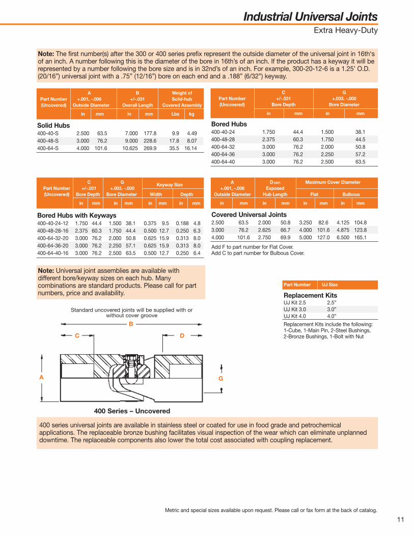
Note: The first number(s) after the 300 or 400 series prefix represent the outside diameter of the universal joint in 16th‘sof an inch. A number following this is the diameter of the bore in 16th’s of an inch. If the product has a keyway it will berepresented by a number following the bore size and is in 32nd’s of an inch. For example, 300-20-12-6 is a 1.25’ O.D.(20/16”) universal joint with a .75” (12/16”) bore on each end and a .188” (6/32”) keyway.
Note: Universal joint assemblies are available with different bore/keywaysizes on each hub. Many combinations are standard products. Pleasecall for part numbers, price and availability.

Industrial Universal JointsExtra Heavy-Duty
10
400 Series
■ Operating angles up to 35 degrees■ Sizes from 2-1/2” to 4”■ Ultimate static strength up to 139,200 lbs-in■ Available with or without lubrication covers■ Select from solid, bored, and keyway hubs■ In addition to the standard items listed, each
hub can have a unique interface geometry■ Available with plain bearings, bronze-sleeved
bearings (field-replaceable wear item to extend universal joint life), and rolling element
■ Plating available upon customer request■ Field/customer rebuild kits available
Cube• Heat treated alloy steel• Precision size for minimum side play• Close alignment holes for smooth operation
Nut• Self-locking
Drive Bushings (2)• Case hardened for wear• Precision ground long life• Press fit into center cube
Bearings (4)• Available with plain bearings,
bronze-sleeved bearings (field-replaceable wear item to extend universal joint life), and rolling element
Main Pin • Case hardened for wear• Precision ground for long life• Slip fit in center cube
Cross bolt• Alloy steel, hex socket head• Provides positive lock on
press fit pins during overload and severe bending
Performance specifications for standard products2-1/2 38,040 4,298 54,000 240,204 22,800 2,576 7,600 8593 61,440 6,942 75,000 333,616 36,800 4,158 12,250 1,3844 139,200 15,728 125,000 556,028 83,500 9,434 28,000 3,164
Metric and special sizes available upon request. Please call or fax form at the back of catalog.
Minimum Ultimate Maximum Maximum Peak TorqueStatic Torsional Ultimate Momentary Stall (for shock load or
Size Strength Axial Strength (overload) Torque reversal conditions)
Lbs-in N-m Lbs N Lbs-in N-m Lbs-in N-m
Industrial Universal JointsExtra Heavy-Duty
11
Solid Hubs400-40-S 2.500 63.5 7.000 177.8 9.9 4.49400-48-S 3.000 76.2 9.000 228.6 17.8 8.07400-64-S 4.000 101.6 10.625 269.9 35.5 16.14
A B Weight ofPart Number +.001, -.006 +/-.031 Solid-hub(Uncovered) Outside Diameter Overall Length Covered Assembly
in mm in mm Lbs kg
Bored Hubs400-40-24 1.750 44.4 1.500 38.1400-48-28 2.375 60.3 1.750 44.5400-64-32 3.000 76.2 2.000 50.8400-64-36 3.000 76.2 2.250 57.2400-64-40 3.000 76.2 2.500 63.5
C GPart Number +/-.031 +.003. -.000(Uncovered) Bore Depth Bore Diameter
in mm in mm
Bored Hubs with Keyways400-40-24-12 1.750 44.4 1.500 38.1 0.375 9.5 0.188 4.8400-48-28-16 2.375 60.3 1.750 44.4 0.500 12.7 0.250 6.3400-64-32-20 3.000 76.2 2.000 50.8 0.625 15.9 0.313 8.0400-64-36-20 3.000 76.2 2.250 57.1 0.625 15.9 0.313 8.0400-64-40-16 3.000 76.2 2.500 63.5 0.500 12.7 0.250 6.4
C GPart Number +/-.031 +.003. -.000
Keyway Size
(Uncovered) Bore Depth Bore Diameter Width Depth
in mm in mm in mm in mm
Part Number UJ Size
Covered Universal Joints2.500 63.5 2.000 50.8 3.250 82.6 4.125 104.83.000 76.2 2.625 66.7 4.000 101.6 4.875 123.84.000 101.6 2.750 69.9 5.000 127.0 6.500 165.1
Add F to part number for Flat Cover.Add C to part number for Bulbous Cover.
Replacement KitsUJ Kit 2.5 2.5”UJ Kit 3.0 3.0”UJ Kit 4.0 4.0”
Replacement Kits include the following:1-Cube, 1-Main Pin, 2-Steel Bushings, 2-Bronze Bushings, 1-Bolt with Nut
A D (REF) Maximum Cover Diameter+.001, -.006 Exposed
Outside Diameter Hub Length Flat Bulbous
in mm in mm in mm in mm
Metric and special sizes available upon request. Please call or fax form at the back of catalog.
400 Series – Uncovered
A
C D
B
G
Standard uncovered joints will be supplied with orwithout cover groove
400 series universal joints are available in stainless steel or coated for use in food grade and petrochemicalapplications. The replaceable bronze bushing facilitates visual inspection of the wear which can eliminate unplanneddowntime. The replaceable components also lower the total cost associated with coupling replacement.
Note: The first number(s) after the 300 or 400 series prefix represent the outside diameter of the universal joint in 16th‘sof an inch. A number following this is the diameter of the bore in 16th’s of an inch. If the product has a keyway it will berepresented by a number following the bore size and is in 32nd’s of an inch. For example, 300-20-12-6 is a 1.25’ O.D.(20/16”) universal joint with a .75” (12/16”) bore on each end and a .188” (6/32”) keyway.
Note: Universal joint assemblies are available withdifferent bore/keyway sizes on each hub. Manycombinations are standard products. Please call for partnumbers, price and availability.
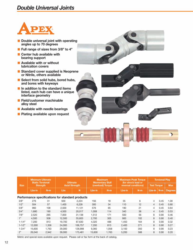
Double Universal Joints
12
■ Double universal joint with operating angles up to 70 degrees
■ Full range of sizes from 3/8” to 4”■ Center hub available with
bearing support■ Available with or without
lubrication covers■ Standard cover supplied is Neoprene
or Nitrile, others available■ Select from solid hubs, bored hubs,
and bores with keyways■ In addition to the standard items
listed, each hub can have a unique interface geometry
■ Field/customer machinable alloy steel
■ Available with needle bearings■ Plating available upon request
Performance specifications for standard products3/8” 276 31 500 2,224 156 18 55 6 4 0.45 1.001/2” 504 57 1,400 6,228 300 34 110 12 4 0.45 0.805/8” 960 108 2,500 11,121 576 65 190 21 4 0.45 0.643/4” 1,680 190 4,500 20,017 1,008 114 340 38 4 0.45 0.537/8” 2,520 285 7,000 31,138 1,512 171 500 56 8 0.90 0.461” 4,500 508 12,500 55,603 2,700 305 900 102 8 0.90 0.401-1/4” 7,200 813 19,700 87,630 4,320 488 1,450 164 8 0.90 0.321-1/2” 12,000 1,356 24,000 106,757 7,200 813 2,400 271 8 0.90 0.271-3/4” 15,600 1,763 29,000 128,998 9,360 1,058 3,100 350 8 0.90 0.232” 26,040 2,942 39,000 173,481 15,600 1,763 5,200 588 8 0.90 0.20
Metric and special sizes available upon request. Please call or fax form at the back of catalog.
Minimum Ultimate Maximum Maximum Peak Torque Torsional PlayStatic Torsional Ultimate Momentary Stall (for shock load or
Size Strength Axial Strength (overload) Torque reversal conditions) Test Torque Max
Lbs-in N-m Lbs N Lbs-in N-m Lbs-in N-m Lbs-in N-m Degrees

A B E KPart Number +.001, -.006 +/-.031 (REF) (REF)(Uncovered) Outside Diameter Overall Length
in mm in mm in mm in mm
Double Universal Joints
13
Solid Hubs300-D-6-S 0.375 9.5 2.625 66.7 0.875 22.2 0.875 22.2300-D-8-S 0.500 12.7 2.938 74.6 0.938 23.8 1.063 27.0300-D-10-S 0.625 15.9 3.313 84.2 1.094 27.8 1.125 28.6300-D-12-S 0.750 19.1 3.813 96.9 1.250 31.8 1.313 33.4300-D-14-S 0.875 22.2 4.500 114.3 1.500 38.1 1.500 38.1300-D-16-S 1.000 25.4 5.000 127.0 1.688 42.9 1.625 41.3300-D-20-S 1.250 31.8 5.563 141.3 1.875 47.6 1.813 46.1300-D-24-S 1.500 38.1 7.000 177.8 2.250 57.1 2.500 63.5300-D-28-S 1.750 44.4 7.875 200.0 2.500 63.5 2.875 73.0300-D-32-S 2.000 50.8 8.750 222.2 2.750 69.8 3.250 82.5400-D-40-S 2.500 63.5 10.500 266.7 3.500 88.9 3.500 88.9400-D-48-S 3.000 76.2 13.750 349.2 4.500 114.3 4.750 120.6400-D-64-S 4.000 101.6 17.000 431.8 5.313 135.0 6.375 161.9
Bored Hubs300-D-6-4 0.375 9.5 0.250 6.3300-D-8-6 0.500 12.7 0.375 9.5300-D-10-8 0.625 15.9 0.500 12.7300-D-12-8 0.750 19.0 0.500 12.7300-D-14-8 0.938 23.8 0.500 12.7300-D-16-10 0.938 23.8 0.625 15.9300-D-20-12 1.000 25.4 0.750 19.0300-D-24-14 1.125 28.6 0.875 22.2300-D-28-16 1.250 31.8 1.000 25.4300-D-32-18 1.375 34.9 1.125 28.6400-D-40-24 1.750 44.4 1.500 38.1400-D-48-28 2.375 60.3 1.750 44.4400-D-64-36 3.000 76.2 2.250 57.1
C GPart Number +/-.031 +.003. -.000(Uncovered) Bore Depth Bore Diameter
in mm in mm
Bored Hubs with Keyways300-D-8-5-2 0.500 12.7 0.313 8.0 0.063 1.6 0.031 0.8300-D-10-5-3 0.625 15.9 0.313 8.0 0.094 2.4 0.047 1.2300-D-12-7-4 0.750 19.1 0.438 11.1 0.125 3.2 0.063 1.6300-D-14-8-4 0.938 23.8 0.500 12.7 0.125 3.2 0.063 1.6300-D-16-10-6 0.938 23.8 0.625 15.9 0.188 4.8 0.094 2.4300-D-20-12-6 1.000 25.4 0.750 19.1 0.188 4.8 0.094 2.4300-D-24-14-6 1.125 28.6 0.875 22.2 0.188 4.8 0.094 2.4S/B300-D-28-16-8 1.250 31.8 1.000 25.4 0.250 6.4 0.125 3.2300-D-32-18-10 1.375 34.9 1.125 28.6 0.313 8.0 0.156 4.0400-D-40-24-12 1.500 38.1 1.500 38.1 0.375 9.5 0.188 4.8400-D-48-28-16 1.750 44.5 1.750 44.5 0.500 12.7 0.250 6.4400-D-64-36-20 2.250 57.2 2.250 57.2 0.625 15.9 0.313 8.0
C GPart Number +/-.031 +.003. -.000
Keyway Size
(Uncovered) Bore Depth Bore Diameter Width Depth
in mm in mm in mm in mm
Covered Universal Joints0.375 9.5 0.531 13.5 0.625 15.9 0.781 19.80.500 12.7 0.500 12.7 0.750 19.1 1.031 26.20.625 15.9 0.625 15.9 0.938 23.8 1.156 29.40.750 19.1 0.688 17.5 1.063 27.0 1.438 36.50.875 22.2 0.859 21.8 1.250 31.8 1.563 39.71.000 25.4 0.984 25.0 1.375 34.9 1.906 48.41.250 31.8 1.031 26.2 1.688 42.9 2.188 55.61.500 38.1 1.219 31.0 1.938 49.2 2.750 69.91.750 44.5 1.375 34.9 2.188 55.6 2.813 71.52.000 50.8 1.438 36.5 2.625 66.7 3.313 84.22.500 63.5 2.000 50.8 3.250 82.6 4.125 104.83.000 76.2 2.625 66.7 4.000 101.6 4.875 123.84.000 101.6 2.750 69.9 5.000 127.0 6.500 165.1
Add F to part number for Flat Cover.Add C to part number for Bulbous Cover.
A D (REF) Maximum Cover Diameter+.001, -.006 Exposed
Outside Diameter Hub Length Flat Bulbous
in mm in mm in mm in mm
Metric and special sizes available upon request. Please call or fax form at the back of catalog.
Double – Uncovered
A
C
E K
D
35°
35°
B
G
Standard uncovered joints will be supplied with orwithout cover groove
70° maximum total working angle
Note: The first number(s) after the 300 or 400 series prefix represent the outside diameter of the universal joint in 16th‘sof an inch. A number following this is the diameter of the bore in 16th’s of an inch. If the product has a keyway it will berepresented by a number following the bore size and is in 32nd’s of an inch. For example, 300-20-12-6 is a 1.25’ O.D.(20/16”) universal joint with a .75” (12/16”) bore on each end and a .188” (6/32”) keyway.

Telescopic/Quick-ChangeQuick-Change Industrial Universal Joints
14
■ Make routine drive train changes and repairs faster than ever
■ Quick-Change design able to be replaced in seconds without tools
■ Eliminates the need for time-consuming alignment of motors
■ Telescopic feature allows for dynamic length change
■ Available from 3/8” to 4” diameter up to 12 feet long
■ Can be covered to extend service life■ Also available as axially free
(no spring) for fixed retention■ Variety of connecting shafts available
to meet application needs
Apex Telescopic/Quick-Change universal joint assembliesconsist of two universal joints mounted at opposite endsof a special spring-loaded connector. Spring tension holdsthe assembly in driving position, yet permits instantremoval by compressing one end of the assembly andlifting it clear.
Press down Pull out
Proper alignment (as shown above in the“correct” diagram) is critical for telescopicapplications.
Incorrect
Correct
“Dynamic” Length Change Application: Position 1
“Dynamic” Length Change Application: Position 2

Telescopic/Quick-ChangeQuick-Change Industrial Universal Joints
15
10-135 Ettco Drill Head X C/F 5 1/4 to 4 5/8 5/16 hex 5/16 hex 5/1610-141 Ettco Drill Head X C/F 7 5/8 to 5 5/16 5/16 hex 5/16 hex 5/8 10-143 Ettco Drill Head X C/F 7 5/8 to 6 1/16 5/16 hex 1/4 hex 5/8 10-144 Ettco Drill Head X C/F 5 1/4 to 4 5/16 5/16 hex 5/16 hex 5/8 10-145 Ettco Drill Head X C/N 5 11/32 to 4 7/16 5/16 hex 3/16 hex 5/8 10-146 Ettco Drill Head X C/F 5 11/32 to 4 7/16 5/16 hex 1/4 hex 5/8 10-171 Ettco Drill Head X C/C 7 5/8 to 5 15/16 5/16 hex 5/16 hex 5/8 14-190 Ettco Drill Head X C/C 8 7/8 to 7 9/16 1/2 hex 7/16 hex 7/8 14-191 Ettco Drill Head X C/C 7 9/16 to 8 7/8 1/2 hex 7/16 hex 7/8 14-192 Ettco Drill Head X C/C 7 15/16 to 9 1/16 1/2 hex 5/15 hex 7/8 UJ-130 U.S. Drill Head X C/F 3 29/32 14 hex 1/4 hex 5/8 x 1/2UJ-248-E U.S. Drill Head X2 F 3 7/8 1/2m. Hex 3/8 5/8 UJ395AUJ395E U.S. Drill Head X C/C 9 to 8 1/4 1/2 hex 1/2 hex 3/4UJ395AUJ248E U.S. Drill Head X C/F 9 to 8 1/4 1/2 hex 3/8 hex 3/4 to 5/8UJ-193-A Johnson Drill Head S C 1 7/16 1/4 hex 25/64 male 1/2 UJ-193-C Johnson Drill Head S F 1 7/16 5/16 hex 1/4 hex 1/2 UJ-296-A Johnson Drill Head S C 1 3/4 5/16 hex 25/64 male 5/8 UJ-296-C Johnson Drill Head S F 1 5/8 5/16 hex 5/16 hex 5/8 UJ-331-A Johnson Drill Head S C 2 1/2 3/8 hex 5/8 male 3/4 UJ-331-H Johnson Drill Head S F 2 1/4 1/2 hex 3/8 hex 3/4 16-610-A Johnson Drill Head S C 2 15/16 1/2 hex 3/4 hex 116-610-H Johnson Drill Head S F 2 1/2 5/8 hex 1/2 hex 120-791-A Johnson Drill Head S C 3 3/4 3/4 hex 7/8 male 1 1/4 20-791-B Johnson Drill Head S F 3 3/4 3/4 hex 3/4 hex 1 1/4 10-249 Burgmaster Drill Head X C/C 9 13/32 1/2-20 male 7/16 male 5/8 16-060 Burgmaster Drill Head S C/C 18 1/2 to 17 1/2 5/8 male 5/8 1UJ-794-A Burgmaster Drill Head S C 3 3/4 5/8 hex 15/16 male 1 1/4 UJ-794-B Burgmaster Drill Head S C 3 3/4 7/8 5/8 hex 1 1/4 20A-537 Burgmaster Drill Head S C 5 1-6B spline 1 1/4 1 1/4 20A-538 Burgmaster Drill Head S C 5 1-6B spline 15/32 1 1/4 32-151 Burgmaster Drill Head S C 5 1/2 1-6B spline 1 14/32 male 232-253 Burgmaster Drill Head S C 5 1/2 1 1/8-6B spline 1 3/8 2UJ-1066-B Jarvis Drill Head X2 N 3 5/8 3/8 m. hex 3/16 hex 3/8
(lower sub assembly)
10-007-B Jarvis Drill Head X2 N 3 5/8 3/8 m. hex 5/16 hex 5/8(lower sub assembly)
12-019-A Jarvis Drill Head X1 C 3 7/8 7/16 hex 3/8 hex 3/4 (upper sub assembly)
12-089-B Jarvis Drill Head X2 N 3 5/8 3/8 m. hex 3/8 hex 3/4 (lower sub assembly)
UJ-233-C Commander Drill Head S C 2 17/32 5/16 3/8 5/8 12-301 Commander Drill Head X C/C 7 21/32 to 6 3/8 3/8 hex 3/8 hex 3/4
Cover Designations: C = Bulbous Cover F = Low Profile Cover N = No CoverHex Designations: Hex = Female hex M. Hex = Male Hex
SpecificationsPart No. Used On Style Cover* B G1 G2 A
Replacement Universal Joints
A+.001-.006A
+.001-.006
LOC DOTSB
G1 G2 A +.001-.006
B
G2G1
X1X2
A -.006+.001
Style S Style X

Military Standard Universal JointsLight-Duty
16
Performance SpecificationsMS-20270-B6 0 4 0.452 1.00 175 19.78 250 28.25 200 890 15° 26 2.94
MS-20270-A8 MS-20270-B8 0 4 0.452 0.80 250 28.25 480 54.24 200 890 15° 38 4.29MS-20270-A10 MS-20270-B10 0 4 0.452 0.64 500 56.50 950 107.35 300 1,335 15° 75 8.48MS-20270-A12 MS-20270-B12 0 4 0.452 0.53 1,000 113.00 1,600 180.80 400 1,779 15° 150 16.95
MS-20270-B14 0 8 0.904 0.46 1,750 197.75 2,500 282.50 500 2,224 15° 262 29.61MS-20270-A16 MS-20270-B16 0 8 0.904 0.40 2,500 282.50 4,500 508.50 600 2,669 15° 375 42.38MS-20270-A20 MS-20270-B20 0 8 0.904 0.32 5,000 565.00 7,000 791.00 800 3,558 15° 750 84.75MS-20270-A24 MS-20270-B24 0 8 0.904 0.27 7,500 847.50 11,500 1,299.50 1,100 4,893 15° 1,125 127.13
DimensionsMS-20270-B6 0.372 9.45 1.750 44.45 0.375 9.52 0.625 15.88 0.250 6.35 0.312 7.92 0.035 0.016
MS-20270-A8 MS-20270-B8 0.495 12.57 1.875 47.62 0.500 12.70 0.625 15.88 0.493 12.52 0.373 9.47 0.375 9.52 0.437 11.10 0.065 0.030MS-20270-A10 MS-20270-B10 0.620 15.75 2.187 55.55 0.625 15.88 0.750 19.05 0.562 14.27 0.436 11.07 0.500 12.70 0.562 14.27 0.095 0.043MS-20270-A12 MS-20270-B12 0.745 18.92 2.500 63.50 0.750 19.05 0.875 22.22 0.743 18.87 0.560 14.22 0.625 15.88 0.687 17.45 0.160 0.073
MS-20270-B14 0.870 22.10 3.000 76.20 0.937 23.80 1.031 26.19 0.750 19.05 0.875 22.22 0.220 0.100MS-20270-A16 MS-20270-B16 0.995 25.27 3.375 85.72 0.937 23.80 1.125 28.57 0.875 22.22 0.686 17.42 0.812 20.62 0.875 22.22 0.385 0.175MS-20270-A20 MS-20270-B20 1.245 31.62 3.750 95.25 1.000 25.40 1.187 30.15 1.187 30.15 0.873 22.17 1.062 26.97 0.937 23.80 0.630 0.286MS-20270-A24 MS-20270-B24 1.495 37.97 4.500 114.30 1.125 28.57 1.375 34.92 1.375 34.92 0.998 25.35 1.250 31.75 1.062 26.97 1.200 0.545
A B C D E F G H Weight+.000, -.002 +/-.015 +.031, -.000 Min +.000, -.005 +.000, -.001 +.004, -.001 +/-.015 Max
Part Number (+.000, -.051) (+/-.381) (+.787, -.000) (+.000, -.127) (+.000, -.025) (+.102, -.025) (+/-.381) (For ‘B’Config.)Diameter OAL Depth/Length Square, A/C Square, A/F Bore Dia. Hole Loc.
Male Square Bored Hub in mm in mm in mm in mm in mm in mm in mm in mm Lbs. kg
Part Number Torsional play Minimum Ultimate Static Torque Axial Tension Endurance Torque Tests
Male Round Test Torque Maximum Specifications Apex Average & Compression Operating TorqueSquare Hub Bored Hub Angle Lbs.-In N-m Degrees Lbs.-in N-m Lbs.-in N-m Lbs.-in N Angle Lbs.-in N-m
MS 270 Series
■ Light-duty MS 270 military standarduniversal joints have undergonequalification testing and meet orexceed the requirements of MilitarySpecification MIL-J-6193 andStandard Drawing MS20270.
MS 270 Series
E
Type B
Type A
F
G
H Inspection hole HB
A
A
DC

Military Standard Universal JointsHeavy-Duty
17
DimensionsMS-20271-B6 0.372 9.45 2.000 50.80 0.500 12.70 0.563 14.30 0.250 6.35 0.437 11.10 0.781 19.84 0.07 0.032MS-20271-B8 0.495 12.57 2.625 66.67 0.625 15.88 0.688 17.48 0.375 9.52 0.562 14.27 1.031 26.19 0.09 0.041MS-20271-B10 0.620 15.75 2.750 69.85 0.750 19.05 0.813 20.65 0.500 12.70 0.687 17.45 1.156 29.36 0.18 0.082MS-20271-B11 0.620 15.75 2.750 69.85 0.750 19.05 0.813 20.65 0.500 12.70 0.687 17.45 1.156 29.36 0.312 7.92 0.18 0.082MS-20271-B12 0.745 18.92 3.187 80.95 0.875 22.22 0.938 23.83 0.625 15.88 0.812 20.62 1.437 36.50 0.24 0.109MS-20271-B14 0.870 22.10 3.625 92.07 1.000 25.40 1.063 27.00 0.750 19.05 0.937 23.80 1.562 39.67 0.35 0.159MS-20271-B16 0.995 25.27 4.062 103.17 1.187 30.15 1.188 30.18 0.812 20.62 1.062 26.97 1.906 48.41 0.55 0.250MS-20271-B20 1.245 31.62 4.625 117.47 1.125 28.57 1.313 33.35 1.062 26.97 1.125 28.57 2.187 55.55 0.90 0.409MS-20271-B24 1.495 37.97 5.250 133.35 1.312 33.32 1.438 36.53 1.250 31.75 1.250 31.75 2.750 69.85 1.50 0.682
A B C D G H J L Weight+.000, -.002 +/-.015 +.031, -.000 Min +.004, -.001 +/-.015 Max Dia. +/-.015 Max
(+.000, -.051) (+/-.381) (+.787, -.000) (+.102, -.025) (+/-.381) (+.102, -.025) (+/-.381)Outside Dia. Overall Length Bore Depth Bore Diameter Insp. Hole Loc. Cover Dia. X-Hole Loc.
Part Number in mm in mm in mm in mm in mm in mm in mm in mm Lbs. kg
MS 271 Series
■ Heavy-duty MS 271 military standarduniversal joints have undergonequalification testing and meet orexceed the requirements of MilitarySpecification MIL-J-6193 andStandard Drawing MS20271.
Performance SpecificationsMS-20271-B6 0 4 0.452 0.83 200 22.60 275 31.08 500 2,224 15° 30 3.39MS-20271-B8 0 4 0.452 0.62 600 67.80 675 76.28 1,000 4,448 15° 90 10.17MS-20271-B10 0 4 0.452 0.50 1,080 122.04 1,200 135.60 1,500 6,672 15° 162 18.31MS-20271-B12 0 4 0.452 0.42 1,900 214.70 2,100 237.30 2,000 8,896 15° 285 32.21MS-20271-B14 0 8 0.904 0.36 3,000 339.00 3,500 395.50 3,500 15,568 15° 450 50.85MS-20271-B16 0 8 0.904 0.32 4,700 531.10 5,500 621.50 5,700 25,354 15° 705 79.67MS-20271-B20 0 8 0.904 0.24 9,500 1,073.50 10,500 1,186.50 7,000 31,136 15° 1,425 161.03MS-20271-B24 0 8 0.904 0.20 14,500 1,638.50 15,500 1,751.50 9,000 40,032 15° 2,175 245.78
Torsional play Minimum Ultimate Static Torque Axial Tension Endurance Torque Tests
Test Torque Maximum Specifications Apex Average & Compression Operating Torque
Part Number Angle Lbs.-in N-m Degrees Lbs.-in N-m Lbs.-in N-m Lbs.-in N-m Angle Lbs.-in N-m
MS 271 Series
J
G
H H
Inspection hole
.194/.190hole thruboth wallsof bothhubs. B11 only
B
A
D DC C

N-m Lbs.-in.TORQUE
HEAVYDUTY
SPEC. ULTIMATETORQUE MIN.
HEAVYDUTY
SPEC. ULTIMATETORQUE MIN.
LIGHTDUTY
SPEC. ULTIMATETORQUE MIN.
LIGHTDUTY
SPEC. ULTIMATETORQUE MIN.
N-m Lbs.-in.TORQUE
1100
1000
120
110
900100
80090
70080
60070
500
400
300
200
100
60
50
40
30
20
101000
100
2000
3000
4000
5000
6000
7000
8000
9000
10000
11000
200
300
400
500
600
700
800
900
1000
1100
1200
0 2 4 6 8 10 12 14 16 18 20 22 0 2 4 6 8 10 12 14 16 18 20 22
Military Standard Universal JointsMS Series
18
Apex military standard universal jointsare designed to strict specifications toassure unsurpassed strength-to-weightratios, torsional and axial overloadcapacity and low torsional deflection.Built to withstand the most demandingconditions, Apex military standard joints
require minimal maintenance; in mostcases, the original may last theservice life of the vehicle or machine.
Apex military standard joints are notadversely affected by fretting corrosionor Brinelling from vibration, shock loadsor overloads.
Available in heavy-duty 271 Seriesor light-duty 270 Series, Apex militarystandard universal joints can beordered with or without protective
lubrication covers. Consult your Apexrepresentative for application details.
High rigidity means low deflection ratesThe deflection curves below prove theaxial and torsional strength of Apexmilitary standard universal joints. Youget maximum overload protection,trouble-free operation and longservice life.
Heavy-Duty Military — 1/2” (12.70 mm)Light-Duty Military — 1/2” (12.70 mm)
Heavy-Duty Military — 1-1/4” (31.75 mm)Light-Duty Military — 1-1/4” (31.75 mm)
DEGREES DEFLECTION

Needle Bearing Universal Joints
19
■ Ideal for high capacity, critical applications
■ Hand-assembled needles eliminate torsional free-play/“Backlash”
■ Designed for continuous duty■ Available in single, double
and telescopic designs■ Midget grease fittings in hubs
allow field lubrication■ Elastomeric cover optional
for harsh environments■ Ideal for applications over 2000 rpms■ Meet performance requirements
of SAE AS39631■ Operating angles up to 25 degrees■ Shaft/hub configurations designed
to meet your application needs
Dimensions and Specifications: Bored Hub12A-100 1.593 40.46 0.750 19.05 0.745 18.92 1.688 42.86 0.625 15.88 0.813 20.64 0.219 5.56 0.755-19.18- 0.531 13.49 0.156 3.97 0.520 0.236 1500 169.5
0.750 19.05
20A-1447* 1.938 49.23 1.125 28.58 1.245 31.62 1,750 44.45 1.062 26.97 1.063 26.99 0.312 7.92 1.005-25.53- 0.688 17.48 0.219 5.56 0.800 0.362 7500 847.51.000 25.40
* Supercedes MS-24312
Bored Hub Spline Hub
A B C D E F G H J L Weight Static+/-.010 in. +/-.016 in. +.000, -.002 in +.004, -.001 in. +/-.016 in. +/-.005 in. +/-.005 in Pilot Max. Torque
Bored Hub+/-.254 mm +/-.397 mm+.000, -.051 mm Swing +.102, -.025 mm+/-.397 mm +/-.127 mm +/-.127 mm Hole Max.
Hub Dia. Dia. Drill
Part Number in mm in mm in mm in mm in mm in mm in mm in mm in mm in mm Lbs. kg Lbs.in N-m
Dimensions and Specifications: Spline Hub (For Bored Hub End See Table Above A thru L)12A-101 2.656 67.46 1.438 36.51 0.57 0.259 1500 169.5 11 0.688 17.4620A-1448** 3.312 84.12 2.000 50.80 1.20 0.544 7500 847.5 15 0.938 23.81**Supercedes MS-24314
16/32 Diameter PitchM N Weight Joint Static Torque External Involute Spline Data
Spline Hub +/-.010 in., +/-.254 mm Min. Total Max. Max.Number Teeth
Pitch Dia. Ref
Part Number in. mm in. mm Lbs. kg Lbs.-in N-m in. mm
Length straightcylindrical section
DN
M
DL
A A
B
E
GJ
HF
C

Instructions to Calculate the Correct Joint Size
20
1. Multiply operating speed (in RPM’s) by operatingangle (in degrees) to get the RPM-working anglefactor (X-Axis).
Intermittent Operation Parameters:• Operating angle less than 5°: On time must notexceed 50% cycle time and cannot be greater than5 minutes.• Operating angle 5°-10°: On time must not exceed30% of total cycle time and cannot be greater than 4minutes.• Operating angle greater than 10°: On time mustnot exceed 20% of total cycle time and cannot begreater than 3 minutes.
For Intermittent Operation:2. Find the intersecting point between transmitted
torque (Y-Axis) and RPM-working angle factor (X-Axis).
3. Choose the universal joint performance curvewhich is directly above the intersecting point fromStep 2.
For Continuous Operation:2. Find the intersecting point between 2 times the
transmitted torque (Y-Axis) and RPM-working anglefactor (X-Axis).
3. Choose the universal joint performance curvewhich is directly above the intersecting point fromStep 2.
N-m Lbs.-in.
TRANSMITTEDTORQUE
RPM WORKING ANGLE FACTOR
110K10K
50K5K
10K
5K
1K
500
1K100
50050
100
1000 3000 5000 7000 9000 11,000 13,000
JOINT SIZE(HUB OUTSIDE DIAMETER)
4.0 In. (101.60 mm)
3.0 In. (76.20 mm)
2.5 In. (63.50 mm)
2.0 In. (50.80 mm)
1.75 In. (44.45 mm)
1.50 In. (38.10 mm)
1.25 In. (31.75 mm)
1.0 In. (25.40 mm)
0.875 In. (22.23 mm)
0.75 In. (19.05 mm)0.625 In. (15.88 mm)
0.50 In. (12.70 mm)
0.375 In. (9.53 mm)
15,000
10
505
10
5
1
1

Request for Information
21
Company Name Address
City State Zip Country
Individual’s Name Title Phone Fax e-mail
1. Application Military Application? ■■ Yes ■■ No
2. Quantity to be quoted:
3. Nature of Operation:
a. Continuous: ■■ (Hours per day ), or, Intermittent: ■■ (Time on Time off
Cycles per day:
b. Operating temperature: Maximum Minimum
b. Non-operating temperature: Maximum Minimum
4. Describe operating environment (such as corrosive, abrasive, extremes in temperature, etc.)
5. Horsepower transmitted by universal joint or torque
6. R.P.M. If variable, state range
7. Operating angle: Maximum angle required
8. Backlash (torsional freeplay) condition desired: ■■ Mil-J-6193 ■■ Mil-U-3963 ■■ Not Critical ■■ Other
MINIMUM CLEARANCE FROM CENTERLINE OFFSET BETWEEN
SHAFTS
UJ Geometry is■■ Male ■■ Female
UJ Geometry is■■ Male
■■ Female
DISTANCE BETWEEN SHAFTS
DISTANCE BETWEENSHAFTS
OVERALL LENGTH
Telescopic & Quick-Change
Double
Single
Request for information only — this is NOT an order. Important: To expedite quote, fill out form completely and FAX to937-228-1736 or use the online form at www.apexuniversal.com.

The total solution from Cooper Power Tools includesnot only a complete line of quality industrial tools andaccessories but also a professional engineering andproduct support staff to help customize each tool tospecific application requirements. All are as close as atelephone or e-mail.
Cooper Power Tools maintains company-ownedService Centers in strategic locations throughout theworld, staffed with professional tool repair technicianswho use genuine Cooper Power Tools parts and who
are outfitted with the very latest in testing,calibration and inspection equipment.
Each tool that is returned to acustomer from one of our ServiceCenters carries with it a warrantythat is Cooper Power Tools’
assurance that it will perform just likeit did when it was purchased new.
Our support personnel are fully capable of helping todiagnose problems and promptly recommend solutions.
Our complete line of tools are carefully designed andbuilt from the finest materials available in order to
provide years of trouble free service. But, as with anypiece of equipment, service problems can occur. Alltools are designed to be easy to service ... that is, ofcourse, with properly trained personnel.
To facilitate quickrepairs, and limitdowntime ...Cooper Power Tools conducts training seminarscovering all aspects of every tool we make.
Introductory training seminars are designed to fullyacquaint students with the entire line of tools and theirfundamental operation. Advanced training seminars,which are often tailored to individual needs, aredesigned to hone the skills of the experiencedstudent. Hands-on experience, with an emphasis ontroubleshooting and repairing, are the focus of thistraining.
Service literature, product information, brand catalogsand FAQs are also available around the clock on theWeb. Just access www.cooperpowertools.comfor the latest information available about any of ourproducts and services.
Training
22

23
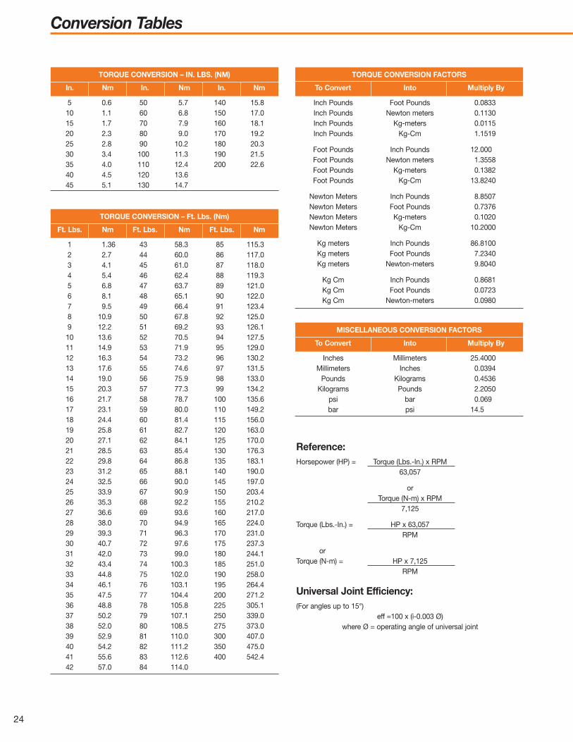
Conversion Tables
24
TORQUE CONVERSION – IN. LBS. (NM)
In. Nm In. Nm In. Nm
5 0.6 50 5.7 140 15.810 1.1 60 6.8 150 17.015 1.7 70 7.9 160 18.120 2.3 80 9.0 170 19.225 2.8 90 10.2 180 20.330 3.4 100 11.3 190 21.535 4.0 110 12.4 200 22.640 4.5 120 13.645 5.1 130 14.7
TORQUE CONVERSION FACTORS
To Convert Into Multiply By
Inch Pounds Foot Pounds 0.0833Inch Pounds Newton meters 0.1130Inch Pounds Kg-meters 0.0115Inch Pounds Kg-Cm 1.1519
Foot Pounds Inch Pounds 12.000Foot Pounds Newton meters 1.3558Foot Pounds Kg-meters 0.1382Foot Pounds Kg-Cm 13.8240
Newton Meters Inch Pounds 8.8507Newton Meters Foot Pounds 0.7376Newton Meters Kg-meters 0.1020Newton Meters Kg-Cm 10.2000
Kg meters Inch Pounds 86.8100Kg meters Foot Pounds 7.2340Kg meters Newton-meters 9.8040
Kg Cm Inch Pounds 0.8681Kg Cm Foot Pounds 0.0723Kg Cm Newton-meters 0.0980
TORQUE CONVERSION – Ft. Lbs. (Nm)
Ft. Lbs. Nm Ft. Lbs. Nm Ft. Lbs. Nm
1 1.36 43 58.3 85 115.32 2.7 44 60.0 86 117.03 4.1 45 61.0 87 118.04 5.4 46 62.4 88 119.35 6.8 47 63.7 89 121.06 8.1 48 65.1 90 122.07 9.5 49 66.4 91 123.48 10.9 50 67.8 92 125.09 12.2 51 69.2 93 126.110 13.6 52 70.5 94 127.511 14.9 53 71.9 95 129.012 16.3 54 73.2 96 130.213 17.6 55 74.6 97 131.514 19.0 56 75.9 98 133.015 20.3 57 77.3 99 134.216 21.7 58 78.7 100 135.617 23.1 59 80.0 110 149.218 24.4 60 81.4 115 156.019 25.8 61 82.7 120 163.020 27.1 62 84.1 125 170.021 28.5 63 85.4 130 176.322 29.8 64 86.8 135 183.123 31.2 65 88.1 140 190.024 32.5 66 90.0 145 197.025 33.9 67 90.9 150 203.426 35.3 68 92.2 155 210.227 36.6 69 93.6 160 217.028 38.0 70 94.9 165 224.029 39.3 71 96.3 170 231.030 40.7 72 97.6 175 237.331 42.0 73 99.0 180 244.132 43.4 74 100.3 185 251.033 44.8 75 102.0 190 258.034 46.1 76 103.1 195 264.435 47.5 77 104.4 200 271.236 48.8 78 105.8 225 305.137 50.2 79 107.1 250 339.038 52.0 80 108.5 275 373.039 52.9 81 110.0 300 407.040 54.2 82 111.2 350 475.041 55.6 83 112.6 400 542.442 57.0 84 114.0
MISCELLANEOUS CONVERSION FACTORS
To Convert Into Multiply By
Inches Millimeters 25.4000Millimeters Inches 0.0394
Pounds Kilograms 0.4536Kilograms Pounds 2.2050
psi bar 0.069bar psi 14.5
Reference:Horsepower (HP) = Torque (Lbs.-In.) x RPM
63,057
orTorque (N-m) x RPM
7,125
Torque (Lbs.-In.) = HP x 63,057RPM
orTorque (N-m) = HP x 7,125
RPM
Universal Joint Efficiency:(For angles up to 15°)
eff =100 x (i-0.003 Ø)where Ø = operating angle of universal joint
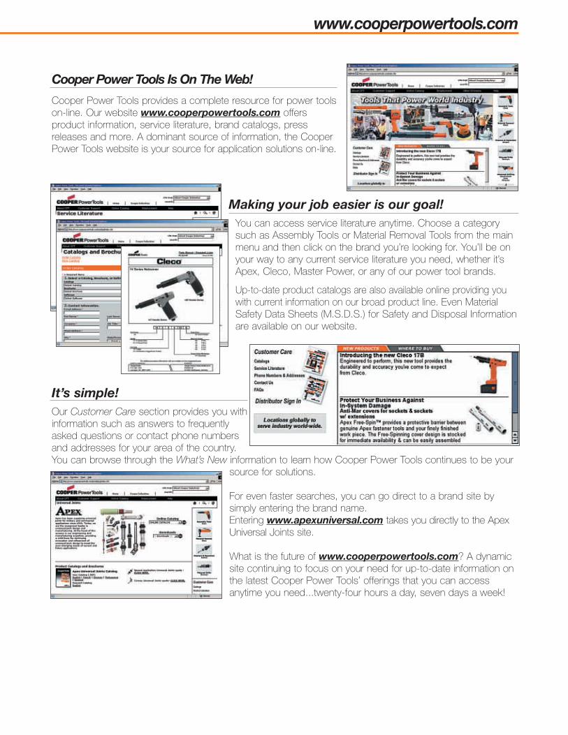
www.cooperpowertools.com
Cooper Power Tools provides a complete resource for power toolson-line. Our website www.cooperpowertools.com offersproduct information, service literature, brand catalogs, pressreleases and more. A dominant source of information, the CooperPower Tools website is your source for application solutions on-line.
Making your job easier is our goal!You can access service literature anytime. Choose a categorysuch as Assembly Tools or Material Removal Tools from the mainmenu and then click on the brand you’re looking for. You’ll be onyour way to any current service literature you need, whether it’sApex, Cleco, Master Power, or any of our power tool brands.
Up-to-date product catalogs are also available online providing youwith current information on our broad product line. Even MaterialSafety Data Sheets (M.S.D.S.) for Safety and Disposal Informationare available on our website.
It’s simple!Our Customer Care section provides you withinformation such as answers to frequentlyasked questions or contact phone numbersand addresses for your area of the country.You can browse through the What’s New information to learn how Cooper Power Tools continues to be your
source for solutions.
For even faster searches, you can go direct to a brand site bysimply entering the brand name. Entering www.apexuniversal.com takes you directly to the ApexUniversal Joints site.
What is the future of www.cooperpowertools.com? A dynamicsite continuing to focus on your need for up-to-date information onthe latest Cooper Power Tools’ offerings that you can accessanytime you need...twenty-four hours a day, seven days a week!
Cooper Power Tools Is On The Web!

MARCH 2007SPECIFICATIONS SUBJECT TO CHANGE WITHOUT NOTICE. © 2007 COOPER INDUSTRIES, INC. PRINTED IN USA. SP-1400-EN 0307 15M
Cooper Power ToolsP.O. Box 1410Lexington, SC 29071-1410USAPhone: 800-845-5629
803-359-1200Fax: 803-359-0822
www.apexuniversal.comCooper (China) Co., Ltd.955 Sheng Li Road,Heqing Pudong, ShanghaiChina 201201Tel: +86-21-28994176
+86-21-28994177Fax: + 86-21-51118446
Cooper Power ToolsGmbH & Company OHGPostfach 30D-73461 WesthausenGermanyPhone: +49-7363-810Fax: +49-7363-81222
Cooper Tools Hungária Kft.Berkenyefa sor 7H-9027 GyörHungaryTel: +36-96-505 300Fax: +36-96-505 301
Cooper Power Tools SASZone industrielle – B.P. 2877831 Ozoir-la-Ferrière CedexFranceTéléphone: +33-1-6443-2200Téléfax: +33-1-6440-1717
Cooper Power Tools de México S.A. de C.V.Libramiento La Joya No. 1 Bodega No. 2Esq. Politécnico Barrio San JoséCuautitlán, Edo de México C.P. 54870Phone: +52-55-5899-9510Fax: +52-55-5870-5012
Cooper Tools Industrial Ltda.Av. Liberdade, 4055Zona Industrial - Iporanga18087-170 Sorocaba, SP BrazilTel: +55-15-3238-3929Fax: +55-15-228-3260
Cooper Power Tools5925 McLaughlin RoadMississauga, OntarioCanada L5R 1B8Phone: (905) 501-4785Fax: (905) 501-4786