universal maxifit - cloudinary · quality management systems to bs en iso 9001 and meets the...
TRANSCRIPT
MaxiFitU
nive
rsal
Mechanical Pipe Fitting technologyWide tolerance range
P i o n e e r s i n P i P e s o l u t i o n s
NOWINcludes
MaxiFit Plus
Overview
MaxiFit
2 Viking Johnson MaxiFit Telephone: +44 (0)1462 443322
MaxiFit Coupling
Large Diameter MaxiDaptor
MaxiStep
MaxiDaptor
MaxiFit Plus Flange Adaptor
MaxiFit Plus Coupling
MaxiThread Large Diameter MaxiFit Coupling Pipe Materials
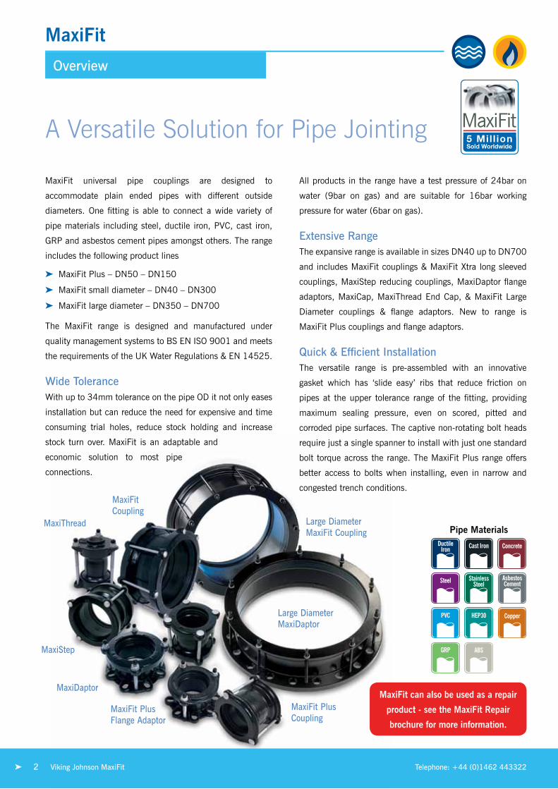
A Versatile Solution for Pipe Jointing
MaxiFit universal pipe couplings are designed to
accommodate plain ended pipes with different outside
diameters. one fitting is able to connect a wide variety of
pipe materials including steel, ductile iron, PVC, cast iron,
GrP and asbestos cement pipes amongst others. the range
includes the following product lines
➤ MaxiFit Plus – Dn50 – Dn150
➤ MaxiFit small diameter – Dn40 – Dn300
➤ MaxiFit large diameter – Dn350 – Dn700
the MaxiFit range is designed and manufactured under
quality management systems to Bs en iso 9001 and meets
the requirements of the uK Water regulations & en 14525.
Wide ToleranceWith up to 34mm tolerance on the pipe oD it not only eases
installation but can reduce the need for expensive and time
consuming trial holes, reduce stock holding and increase
stock turn over. MaxiFit is an adaptable and
economic solution to most pipe
connections.
All products in the range have a test pressure of 24bar on
water (9bar on gas) and are suitable for 16bar working
pressure for water (6bar on gas).
Extensive Rangethe expansive range is available in sizes Dn40 up to Dn700
and includes MaxiFit couplings & MaxiFit Xtra long sleeved
couplings, Maxistep reducing couplings, MaxiDaptor flange
adaptors, MaxiCap, Maxithread end Cap, & MaxiFit large
Diameter couplings & flange adaptors. new to range is
MaxiFit Plus couplings and flange adaptors.
Quick & Efficient Installationthe versatile range is pre-assembled with an innovative
gasket which has ‘slide easy’ ribs that reduce friction on
pipes at the upper tolerance range of the fitting, providing
maximum sealing pressure, even on scored, pitted and
corroded pipe surfaces. the captive non-rotating bolt heads
require just a single spanner to install with just one standard
bolt torque across the range. the MaxiFit Plus range offers
better access to bolts when installing, even in narrow and
congested trench conditions.
MaxiFit can also be used as a repair
product - see the MaxiFit Repair
brochure for more information.
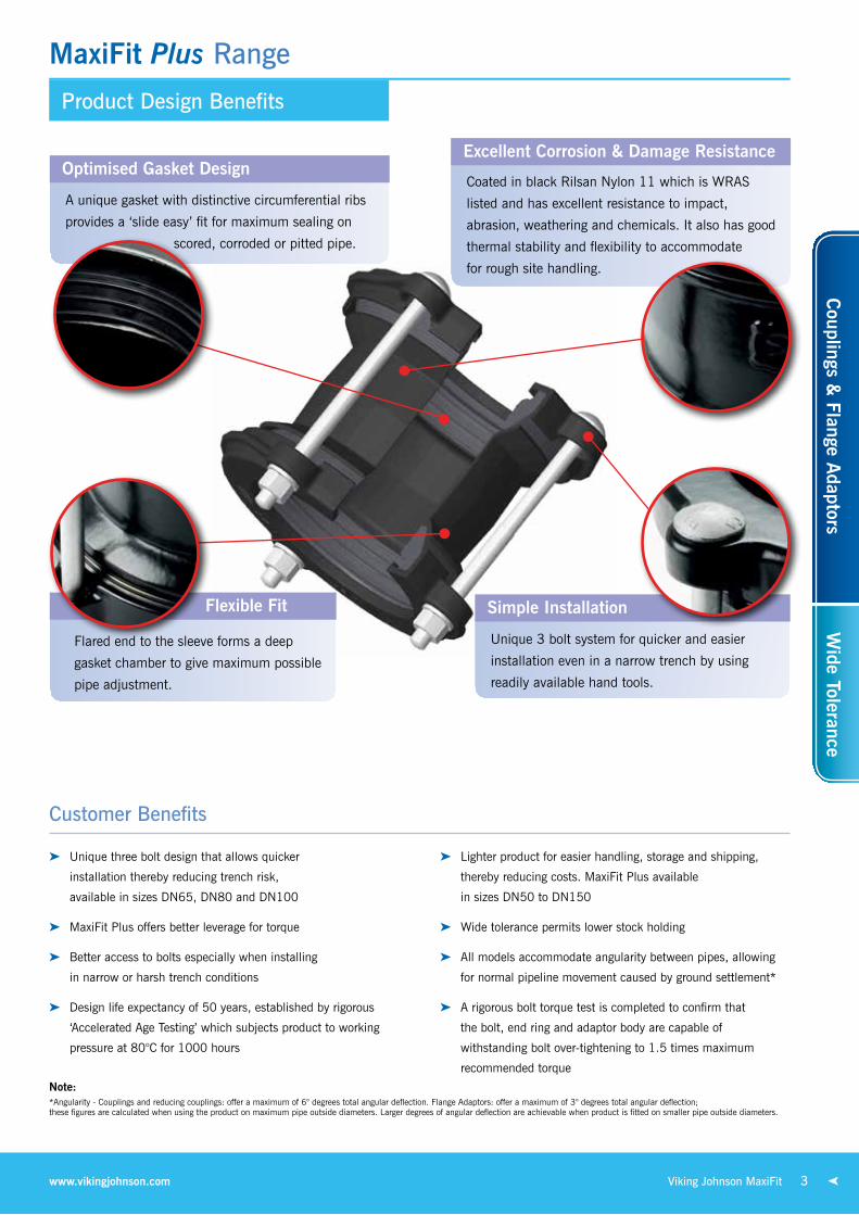
Product Design Benefits
MaxiFit Plus Range
3Viking Johnson MaxiFitwww.vikingjohnson.com
Excellent Corrosion & Damage Resistance
Coated in black rilsan nylon 11 which is WrAs
listed and has excellent resistance to impact,
abrasion, weathering and chemicals. it also has good
thermal stability and flexibility to accommodate
for rough site handling.
Simple Installation
unique 3 bolt system for quicker and easier
installation even in a narrow trench by using
readily available hand tools.
Flexible Fit
Flared end to the sleeve forms a deep
gasket chamber to give maximum possible
pipe adjustment.
Optimised Gasket Design
A unique gasket with distinctive circumferential ribs
provides a ‘slide easy’ fit for maximum sealing on
scored, corroded or pitted pipe.
Customer Benefits
➤ unique three bolt design that allows quicker
installation thereby reducing trench risk,
available in sizes Dn65, Dn80 and Dn100
➤ MaxiFit Plus offers better leverage for torque
➤ Better access to bolts especially when installing
in narrow or harsh trench conditions
➤ Design life expectancy of 50 years, established by rigorous
‘Accelerated Age testing’ which subjects product to working
pressure at 80°C for 1000 hours
➤ lighter product for easier handling, storage and shipping,
thereby reducing costs. MaxiFit Plus available
in sizes Dn50 to Dn150
➤ Wide tolerance permits lower stock holding
➤ All models accommodate angularity between pipes, allowing
for normal pipeline movement caused by ground settlement*
➤ A rigorous bolt torque test is completed to confirm that
the bolt, end ring and adaptor body are capable of
withstanding bolt over-tightening to 1.5 times maximum
recommended torque
Note:*Angularity - Couplings and reducing couplings: offer a maximum of 6° degrees total angular deflection. Flange Adaptors: offer a maximum of 3° degrees total angular deflection; these figures are calculated when using the product on maximum pipe outside diameters. larger degrees of angular deflection are achievable when product is fitted on smaller pipe outside diameters.
Couplings &
Flange Adaptors
Wide Tolerance

MaxiFit Plus DN50 – DN150
Specifications
End Ring and Adaptor BodyDuctile iron to Bs en 1563 symbol en GJs-450-10
Centre Sleevesleeve material is rolled steel to Bs en10025-2 grade s275 or Ductile iron to Bs en1563 symbol en GJs-450-10 Compliance with en 14525
GasketePDM compound Grade e to Bs en 681-1, type WA, WC
nitrile compound to Grade G Bs en 682, type G
Tee Bolts/Boltssteel to Bs en iso 898-1 Property Class 4.8
Bolt Torque/SpannerBolt torque 55-65nm, spanner size A/F 19mm
Nutssteel to Bs en 4190 Grade 4
Washersstainless steel to Bs 1449:Part 2 Grade 304s15 standard
Materials & Relevant Standards
MaxiFit Plus Couplings & End Caps
MaxiFit Plus Flange Adaptors
MaxiFit PlusMaxiFitMaxiFit XtraMaxiStepMaxiDaptorMaxiFit Large DiameterMaxiCapMaxiThread End Cap
For further info visit:www.vikingjohnson.com
The full MaxiFit Range consists of:
Note:For other sizes of flange adapters, please see MaxiDapter Flange Adapter section. *Angularity - Couplings and reducing couplings: offer a maximum of 6° degrees total angular deflection. Flange Adaptors: offer a maximum of 3° degrees total angular deflection; these figures are calculated when using the product on maximum pipe outside diameters. larger degrees of angular deflection are achievable when product is fitted on smaller pipe outside diameters.
Nominalsize(mm)
size Range(mm)
diameter(mm)
Bore(mm)
Overalllength(mm)
L
sleeve length x Thickness
Flangedrilling
setting Gap(mm)
BoltsNo-dia X length
GasketMould
WeightKg
Min Max M S (A) x (T) Min Max
DN65 63 85 196.9 75 124 75 x 5
60 PN10:16, 65 PN10:16, 80 PN10:16, 3” BS10 Table ADE, 2.5” ANSI125, 3” ANSI125, 80 AS2129 CD, 80 AS4087 16
20 40 3-M12 x 115 12392/2 3.6
DN80 85 107 202.5 101 124 75 x 580 PN10:16, 3”ANSI125, 3.5” BS10 Table AD, 3.5” BS10 Table E
20 40 3-M12 x 115 12392/3 3.8
DN100 107 132 228 121 134 75 x 5100 PN10:16, 4” BS10 Table AD, 4” BS10 Table E, 4” AWWAC207 D 100 AS2129 CD, 100 AS4087 16
20 40 3-M12 x 125 12392/4 4.7
l
A
M
t
setting GapMaximum Gap
l
A
s
t
setting GapMaximum Gap
M M
axim
um F
lang
e
Coupling Flange Adaptor
Nominalsize(mm)
size Range(mm)
diameter(mm)
Overalllength(mm)
L
sleeve length x Thickness
sleeve
setting Gap(mm)
BoltsNo-dia X length
GasketMould
WeightKg
Maxicap Available
Min Max M (A) x (T) Min Max
DN50 57 74 154.5 190 95 x 3 Steel 20 40 4-M12x180 12392/1 2.7 ✓
DN65 63 85 173.5 190 95 x 4.5 Ductile Iron 20 40 3-M12x180 12392/2 3.6 ✓
DN65 63 85 173.5 190 95 x 3 Steel 20 40 3-M12x180 12392/2 3.2 ✓
DN80 85 107 195.5 190 95 x 4.5 Ductile Iron 20 40 3-M12x180 12392/3 4.1 ✓
DN80 85 107 195.5 190 95 x 3 Steel 20 40 3-M12x180 12392/3 3.7 ✓
DN100 107 132 224.5 190 95 x 4.5 Ductile Iron 20 40 3-M12x180 12392/4 5.0 ✓
DN100 107 132 224.5 190 95 x 3 Steel 20 40 3-M12x180 12392/4 4.5 ✓
DN125 132 158 254.5 190 95 x 3 Steel 20 40 4-M12x180 12392/6 5.2 ✓
DN150 158 184 280.5 190 95 x 3 Steel 20 40 4-M12x180 12392/7 6 ✓
4 Viking Johnson MaxiFit Telephone: +44 (0)1462 443322

MaxiFit Range
Product Design Benefits
Optimised Gasket Design
Excellent Corrosion & Damage Resistance
Simple InstallationFlexible Fit
➤ Design life expectancy of 50 years,
established by rigorous ‘Accelerated
Age testing’ which subjects product
to working pressure at 80°C for
1000 hours.
➤ Wide tolerances permit lower
stock holding.
➤ All models accommodate angularity
between pipes which allows for
normal pipeline movement caused
by ground settlement. Couplings and
reducing couplings allowing for 6°
total angular deflection 3° total
on the flange adaptors.
➤ A rigorous bolt torque test is
completed to confirm that the
bolt, end ring and adaptor body
are capable of withstanding bolt
over-tightening to 1.5 times
maximum recommended torque.
Customer Benefits
A unique gasket with distinctive circumferential ribs
provides a ‘slide easy’ fit for maximum sealing on
scored, corroded or pitted pipe.
Coated in black rilsan nylon 11 which is WrAs
listed and has excellent resistance to impact,
abrasion, weathering and chemicals. it also has good
thermal stability and flexibility to accommodate
for rough site handling.
Flared end to the sleeve forms a deep
gasket chamber to give maximum possible
pipe adjustment.
Captive, non-rotating bolt heads require just
a torque wrench to install.
5Viking Johnson MaxiFitwww.vikingjohnson.com
Couplings &
Flange Adaptors
Wide Tolerance

MaxiFit, MaxiFit Xtra & MaxiStep
MaxiDaptor
Product Design Benefits
Product Design Benefits
Simple Installation
Excellent Repair Product
Available as standard and long sleeved versions, the
MaxiFit Xtra simplifies the installation further, allowing
for greater cutting tolerances and a greater pipe insertion
depth - sealing beyond corrosion damaged pipe ends to
create a safe and permanent repair.
Maxistep reducing couplings are designed to provide
transitions between pipes of different nominal
bores simplifying installations when repairing old
pipe with new.
Accommodates Pipe Movement
All models accommodate angularity between pipes
which allows for normal pipeline movement due to
ground settlement. Couplings and reducing couplings
allow for 6° total angular deflection.
Exceptional Sealing Capabilities
Flanges have an extended sealing face.
Accommodates Pipe Movement
All models accommodate angularity between pipes
which allows for normal pipeline movement caused
by to ground settlement. Flange adaptors have a total
angular deflection of 3°.
Ultimate Flexibility
All cast flanges have multi drilling including; Bs en
1092-1, iso 7005 1:1992, (Pn10/16), Bs10: 1962
(table ADe), Ansi/AWWA.
6 Viking Johnson MaxiFit Telephone: +44 (0)1462 443322

Specifications
MaxiFit & MaxiFit Xtra Couplings & End Caps
Coupling - Standard Sleeve (MaxiFit)
Nominal size(mm)
size Range(mm)
diameter(mm)
Overalllength (mm)
sleevelength x Thickness
setting Gap(mm) Bolts
No.-dia x lengthGasket
Mould No.Weight
(kg)MaxicapAvailable
MaximumThreaded
Outlet
MaxiFit Plus Available
Min Max M L (A) x (T) Min Max
DN40 47.9 59.5 149.5 190.0 100.0 x 4.5 20.0 40.0 2-M12 x 180 1637 3.1
DN50 57.0 74.0 154.5 190.0 95.0 x 4.5 20.0 40.0 4-M12 x 180 12392/1 3.0 ✓ 1” ✓
DN65 63.0 85.0 173.5 190.0 95.0 x 4.5 20.0 40.0 4-M12 x 180 12392/2 3.6 ✓ 1” ✓
DN80 85.0 107.0 195.5 190.0 95.0 x 4.5 20.0 40.0 4-M12 x 180 12392/3 4.1 ✓ 2” ✓
DN100 107.0 132.0 224.5 190.0 95.0 x 4.5 20.0 40.0 4-M12 x 180 12392/4 5.0 ✓ 2” ✓
DN125 132.0 158.0 254.5 190.0 95.0 x 5.0 20.0 40.0 4-M12 x 180 12392/6 6.1 ✓ 2” ✓
DN150 158.0 184.0 280.5 190.0 95.0 x 5.0 20.0 40.0 4-M12 x 180 12392/7 7.0 ✓ 2” ✓
DN175 189.0 212.0 306.5 230.0 130.0 x 5.0 25.0 50.0 4-M12 x 220 12392/9 9.4 ✓ 2”
DN200 218.0 244.0 342.5 230.0 130.0 x 5.0 25.0 50.0 4-M12 x 220 12392/10 10.9 ✓ 2”
DN225 243.0 269.0 367.5 230.0 130.0 x 5.0 25.0 50.0 6-M12 x 220 12392/11 12.4 ✓ 2”
DN250 266.0 295.0 399.5 230.0 130.0 x 5.0 25.0 50.0 6-M12 x 220 12392/12 14.6 ✓ 2”
DN300 315.0 349.0 462.5 230.0 130.0 x 5.0 25.0 50.0 8-M12 x 220 12392/14 19.4 ✓ 2”
Coupling - Long Sleeve (MaxiFit Xtra)
DN50 57.0 74.0 154.5 285.0 200.0 x 5.5 20.0 140.0 4-M12 x 275 12392/1 4.6 ✓ 1”
DN65 63.0 85.0 173.5 285.0 190.0 x 5.5 20.0 130.0 4-M12 x 275 12392/2 5.2 ✓ 1”
DN80 85.0 107.0 195.5 285.0 200.0 x 5.5 20.0 140.0 4-M12 x 275 12392/3 6.3 ✓ 2”
DN100 107.0 132.0 224.5 285.0 190.0 x 5.5 20.0 130.0 4-M12 x 275 12392/4 7.2 ✓ 2”
DN125 132.0 158.0 254.5 285.0 190.0 x 6.0 20.0 130.0 4-M12 x 275 12392/6 9.0 ✓ 2”
DN150 158.0 184.0 280.5 285.0 190.0 x 6.0 20.0 130.0 4-M12 x 275 12392/7 10.3 ✓ 2”
DN175 189.0 212.0 306.5 285.0 190.0 x 6.0 25.0 110.0 4-M12 x 275 12392/9 12.1 ✓ 2”
DN200 218.0 244.0 342.5 285.0 190.0 x 6.0 25.0 110.0 4-M12 x 275 12392/10 14.1 ✓ 2”
DN225 243.0 269.0 367.5 350.0 250.0 x 6.0 25.0 165.0 6-M12 x 340 12392/11 18.6 ✓ 2”DN250 266.0 295.0 399.5 350.0 250.0 x 6.0 25.0 165.0 6-M12 x 340 12392/12 21.4 ✓ 2”DN300 315.0 349.0 462.5 350.0 240.0 x 6.0 25.0 155.0 8-M12 x 340 12392/14 27.0 ✓ 2”
setting Gap Maximum Gap
M
l
A
t
Coupling
Working Pressure = 16bar (water) 6bar (gas)
Materials & Relevant Standards
End Ring and Adaptor Body/Centre SleeveDuctile iron to Bs en 1563 symbol en GJs-450-10
GasketePDM compound Grade e to Bs en 681-1, type WA, WC nitrile compound to Grade G Bs en 682, type G
Tee Bolts/Boltssteel to Bs en iso 898-1 Property Class 4.8
Bolt Torque/SpannerBolt torque 55-65nm, spanner size A/F 19mm
Nutssteel to Bs en 4190 Grade 4
Washersstainless steel to Bs 1449:Part 2 Grade 304s15 standard
every effort has been made to ensure that the information contained in this publication is accurate at the time of publishing. Crane ltd assumes no responsibility or liability for typographical errors or omissions or for any misinterpretation of the information within the publication and reserves the right to change without notice.
7Viking Johnson MaxiFitwww.vikingjohnson.com
Couplings &
Flange Adaptors
Wide Tolerance
Specifications
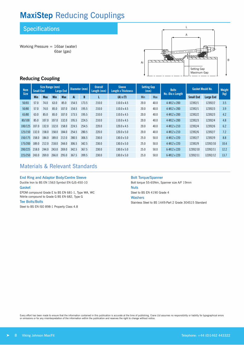
MaxiStep Reducing Couplings
Nom size
size Range (mm)small end large end diameter (mm) Overall
length (mm)sleeve
length x Thicknesssetting Gap
(mm) BoltsNo.-dia x length
Gasket Mould No. Weight(kg)
Min Max Min Max Ai B l (A) x (T) Min Max small end large end
50/65 57.0 74.0 63.0 85.0 154.5 173.5 210.0 110.0 x 4.5 20.0 40.0 4-M12 x 200 12392/1 12392/2 3.5
50/80 57.0 74.0 85.0 107.0 154.5 195.5 210.0 110.0 x 4.5 20.0 40.0 4-M12 x 200 12392/1 12392/3 3.9
65/80 63.0 85.0 85.0 107.0 173.5 195.5 210.0 110.0 x 4.5 20.0 40.0 4-M12 x 200 12392/2 12392/3 4.2
80/100 85.0 107.0 107.0 132.0 195.5 224.5 210.0 110.0 x 4.5 20.0 40.0 4-M12 x 200 12392/3 12392/4 4.8
100/125 107.0 132.0 132.0 158.0 224.5 254.5 220.0 120.0 x 4.5 20.0 40.0 4-M12 x 210 12392/4 12392/6 6.2
125/150 132.0 158.0 158.0 184.0 254.5 280.5 220.0 120.0 x 5.0 20.0 40.0 4-M12 x 210 12392/6 12392/7 7.2
150/175 158.0 184.0 189.0 212.0 280.5 306.5 230.0 130.0 x 5.0 25.0 50.0 4-M12 x 220 12392/7 12392/9 8.8
175/200 189.0 212.0 218.0 244.0 306.5 342.5 230.0 130.0 x 5.0 25.0 50.0 4-M12 x 220 12392/9 12392/10 10.4
200/225 218.0 244.0 243.0 269.0 342.5 367.5 230.0 130.0 x 5.0 25.0 50.0 6-M12 x 220 12392/10 12392/11 12.2
225/250 243.0 269.0 266.0 295.0 367.5 399.5 230.0 130.0 x 5.0 25.0 50.0 6-M12 x 220 12392/11 12392/12 13.7
Reducing Coupling
Ai
A
B
l
t
setting Gap Maximum Gap
Working Pressure = 16bar (water) 6bar (gas)
Materials & Relevant Standards
End Ring and Adaptor Body/Centre SleeveDuctile iron to Bs en 1563 symbol en GJs-450-10
GasketePDM compound Grade e to Bs en 681-1, type WA, WC nitrile compound to Grade G Bs en 682, type G
Tee Bolts/Boltssteel to Bs en iso 898-1 Property Class 4.8
Bolt Torque/SpannerBolt torque 55-65nm, spanner size A/F 19mm
Nutssteel to Bs en 4190 Grade 4
Washersstainless steel to Bs 1449:Part 2 Grade 304s15 standard
every effort has been made to ensure that the information contained in this publication is accurate at the time of publishing. Crane ltd assumes no responsibility or liability for typographical errors or omissions or for any misinterpretation of the information within the publication and reserves the right to change without notice.
8 Viking Johnson MaxiFit Telephone: +44 (0)1462 443322

Specifications
MaxiDaptor Flange Adaptors
Flange Adaptor
s
M M
axim
um F
lang
e
l
A
t
setting Gap Maximum Gap
Working Pressure = 16bar (water) 6bar (gas)
Nom size
size Range(mm)
diameter(mm)
Bores(mm)
Overalllength (mm)
sleevelength x Thickness Flange drilling
setting Gap(mm)
BoltsNo.-dia x length
Gasket Mould No.
Weight(kg)
MaxiFit Plus
AvailableMin Max M s l (A) x (T) Min Max
50 57.0 74.0 163.4 59.0 124.0 75.0 x 5.0 50 PN10:16, 2.5" BS10 Table ADE,2" ANSI125 20.0 40.0 4-M12 x 115 12392/1 2.7
65 63.0 85.0 196.9 75.0 124.0 75.0 x 5.0
60 PN10:16, 65 PN10:16, 80 PN10:16, 3" BS10 Table ADE,2.5" ANSI125, 3" ANSI12580 AS2129 CD, 80 AS4087 16
20.0 40.0 4-M12 x 115 12392/2 3.5 ✓
80 85.0 107.0 202.5 101.0 124.0 75.0 x 5.080 PN10:16, 3"ANSI125,3.5" BS10 Table AD, 3.5" BS10 Table E
20.0 40.0 4-M12 x 115 12392/3 3.7 ✓
100 107.0 132.0 228.0 121.0 134.0 75.0 x 5.0100 PN 10:16, 4" BS10 Table AD,4" BS10 Table E, 4" AWWA C207 D, 100 AS2129 CD, 100 AS4087 16
20.0 40.0 4-M12 x 125 12392/4 4.4 ✓
125 132.0 158.0 281.5 150.0 134.0 75.0 x 5.0
125 PN10:16, 150 PN10:165" BS10 Table A, 5" BS10 Table DE, 6" BS10 Table A, 6" BS10 Table D, 6" BS10 Table E, 6" AWWA C207 D,125 AS2129 CD, 150 AS2129 CD,125 AS4087 16, 150 AS4087 16
20.0 40.0 4-M12 x 125 12392/6 5.6
150 158.0 184.0 281.2 173.0 134.0 75.0 x 5.0150 PN10:16, 6" BS10 Table A, 6" BS10 Table D, 6" AWWA, C207 D, 150 AS4087 16, 150 AS2129 CD,
20.0 40.0 4-M12 x 125 12392/7 6.0
175 189.0 212.0 336.5 202.0 133.0 75.0 x 5.0200 PN10:16, 8" BS10 Table AD,8" AWWA C207 D, 200 AS2129 CD, 200 AS4087 16
25.0 40.0 4-M12 x 125 12392/9 8.3
200 218.0 244.0 337.8 225.0 134.0 75.0 x 5.0 200 PN10:16, 8" BS10 Table AD, 8" AWWA C207 D, 200 AS2129 CD 25.0 40.0 4-M12 x 125 12392/10 8.3
225 243.0 269.0 401.5 252.0 144.0 85.0 x 5.0 250 PN10:16, 250 AS4087 16 25.0 50.0 6-M12 x 135 12392/11 10.9
250 266.0 295.0 402.1 277.0 146.0 85.0 x 5.0 250 PN10:16, 250 AS4087 16 25.0 50.0 6-M12 x 135 12392/12 11.4
300 315.0 349.0 457.8 329.0 155.0 100.0 x 5.0 300 PN10:16, 12" BS10 Table D,300 AS2129 CD 25.0 60.0 6-M12 x 145 12392/14 14.8
Materials & Relevant Standards
End Ring and Adaptor Body/Centre SleeveDuctile iron to Bs en 1563 symbol en GJs-450-10
GasketePDM compound Grade e to Bs en 681-1, type WA, WC nitrile compound to Grade G Bs en 682, type G
Tee Bolts/Boltssteel to Bs en iso 898-1 Property Class 4.8
Bolt Torque/SpannerBolt torque 55-65nm, spanner size A/F 19mm
Nutssteel to Bs en 4190 Grade 4
Washersstainless steel to Bs 1449:Part 2 Grade 304s15 standard
every effort has been made to ensure that the information contained in this publication is accurate at the time of publishing. Crane ltd assumes no responsibility or liability for typographical errors or omissions or for any misinterpretation of the information within the publication and reserves the right to change without notice.
9Viking Johnson MaxiFitwww.vikingjohnson.com
Couplings &
Flange Adaptors
Wide Tolerance

United Kingdom - Lancashire
Hodder AqueductMaxistep reducing Coupling - Dn700
Project relining & Cleaning scheme -
the 28 mile Hodder Aqueduct
was originally constructed in
1925 by Flyde Water Board to
supply water to Blackpool from
stocks reservoir.
Client united utilities
10 Viking Johnson MaxiFit Telephone: +44 (0)1462 443322
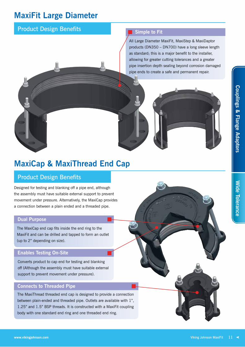
MaxiFit Large Diameter
MaxiCap & MaxiThread End Cap
Product Design Benefits
Product Design Benefits
Simple to Fit
All large Diameter MaxiFit, Maxistep & MaxiDaptor
products (Dn350 – Dn700) have a long sleeve length
as standard; this is a major benefit to the installer,
allowing for greater cutting tolerances and a greater
pipe insertion depth sealing beyond corrosion damaged
pipe ends to create a safe and permanent repair.
Designed for testing and blanking off a pipe end, although
the assembly must have suitable external support to prevent
movement under pressure. Alternatively, the MaxiCap provides
a connection between a plain ended and a threaded pipe.
Enables Testing On-Site
Converts product to cap end for testing and blanking
off (Although the assembly must have suitable external
support to prevent movement under pressure).
Connects to Threaded Pipe
the Maxithread threaded end cap is designed to provide a connection
between plain-ended and threaded pipe. outlets are available with 1”,
1.25” and 1.5” BsP threads. it is constructed with a MaxiFit coupling
body with one standard end ring and one threaded end ring.
Dual Purpose
the MaxiCap end cap fits inside the end ring to the
MaxiFit and can be drilled and tapped to form an outlet
(up to 2” depending on size).
11Viking Johnson MaxiFitwww.vikingjohnson.com
Couplings &
Flange Adaptors
Wide Tolerance

Specifications
MaxiFit Large Diameter Couplings
Coupling
1 = sleeve 2 = end ring
3 = Gasket 4 = Bolts, nuts & Washer
Working Pressure = 16bar (water) 6bar (gas)
Od Range dimensionsGasket Mould No. Bolts
No.-dia x lengthWeight
(kg)Min (mm) Max (mm) end Ring diameter A (mm)
351.0 368.0 478.0 6002 8-M12 x 340 30.1374.5 391.5 501.5 1659 8-M12 x 340 31.9386.0 403.0 513.0 6035 8-M12 x 340 32.6394.3 411.3 521.5 1766 8-M12 x 340 33.2404.8 421.8 532.0 1767 8-M12 x 340 34.0412.0 429.0 539.0 6023 10-M12 x 340 35.1418.2 435.2 545.0 1784 8-M12 x 340 34.9425.0 442.0 552.0 1662 8-M12 x 340 35.5434.5 451.5 561.5 1768 10-M12 x 340 37.0439.0 456.0 566.0 6036 10-M12 x 340 37.3447.2 464.2 574.0 1769 10-M12 x 340 37.9455.0 472.0 582.0 6003 10-M12 x 340 38.5467.0 484.0 594.0 6073 10-M12 x 340 39.3476.0 493.0 603.0 1770 10-M12 x 340 39.9487.0 504.3 614.5 1771 10-M12 x 340 40.7492.0 509.0 619.0 6037 10-M12 x 340 41.1501.9 518.9 629.0 1772 10-M12 x 340 41.8510.0 527.0 637.0 6004 10-M12 x 340 42.3515.0 532.0 642.0 6024 10-M12 x 340 42.8527.0 544.0 654.0 1773 12-M12 x 340 44.1540.1 557.1 667.0 1774 10-M12 x 340 44.5546.0 563.0 673.0 6038 12-M12 x 340 45.5555.3 572.3 682.5 1775 12-M12 x 340 46.1565.0 582.0 692.0 1776 12-M12 x 340 46.8582.2 599.2 709.0 1777 12-M12 x 340 48.0593.0 610.0 720.0 6021 12-M12 x 340 48.8601.0 618.0 728.0 6020 12-M12 x 340 49.4613.0 630.0 740.0 6019 12-M12 x 340 50.3618.0 635.0 745.0 6025 12-M12 x 340 50.6630.0 647.0 757.0 1778 14-M12 x 340 52.0645.2 662.2 772.0 1779 14-M12 x 340 53.0654.0 671.0 781.0 6039 14-M12 x 340 53.8662.0 679.0 789.0 1780 14-M12 x 340 54.3675.0 692.0 802.0 6005 14-M12 x 340 55.2689.0 706.0 816.0 10511/49 14-M12 x 340 56.3695.0 712.0 822.0 6063 14-M12 x 340 56.7710.0 727.0 837.0 6075 14-M12 x 340 57.7
1
4
2
33
2
Materials & Relevant Standards
Sleeverolled steel to Bs en 10025-2 Grade s275
End Ringrolled steel to Bs en 10025-2 Grade s275
GasketePDM Grade “e” to Bs en 681-1 type WA WrAs listed
Bolt Torque / SpannerBolt torque - 55-65nm / Spanner size - A/F 19mm
Bolts, Nuts & WasherBolts - steel to Bs en iso 898-1 Property Class 4.8 Nuts - steel to Bs en 4190 Grade 4 Washer - stainless steel to Bs 1449:Part 2 Grade 304 s15
CoatingSleeve & End Ring = rilsan nylon 11 to Wis 4-52-01 Part 1 Bolts & Nuts = sheraplex to Wis 4-52-03
every effort has been made to ensure that the information contained in this publication is accurate at the time of publishing. Crane ltd assumes no responsibility or liability for typographical errors or omissions or for any misinterpretation of the information within the publication and reserves the right to change without notice.
12 Viking Johnson MaxiFit Telephone: +44 (0)1462 443322
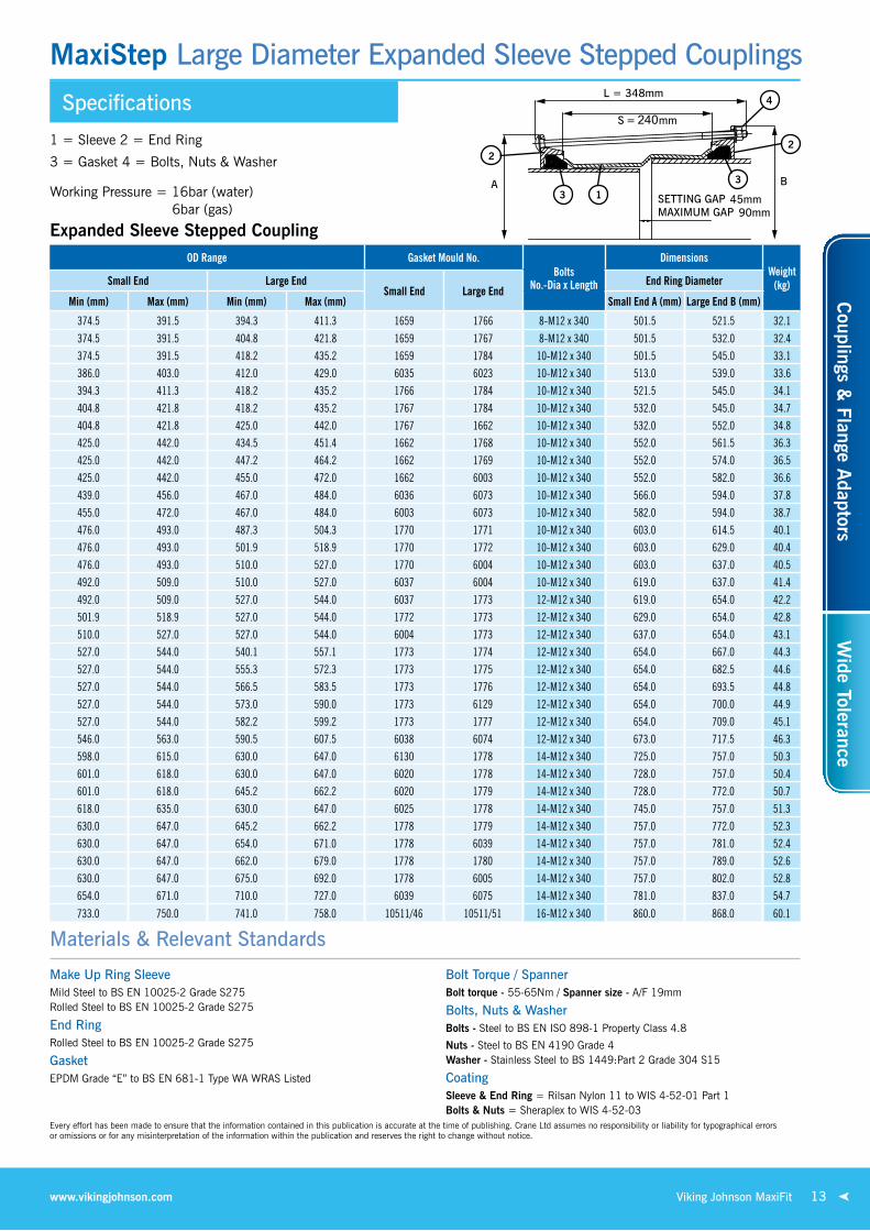
Specifications
MaxiStep Large Diameter Expanded Sleeve Stepped Couplings
Expanded Sleeve Stepped CouplingOd Range Gasket Mould No.
BoltsNo.-dia x length
dimensionsWeight
(kg)small end large endsmall end large end
end Ring diameter
Min (mm) Max (mm) Min (mm) Max (mm) small end A (mm) large end B (mm)
374.5 391.5 394.3 411.3 1659 1766 8-M12 x 340 501.5 521.5 32.1
374.5 391.5 404.8 421.8 1659 1767 8-M12 x 340 501.5 532.0 32.4374.5 391.5 418.2 435.2 1659 1784 10-M12 x 340 501.5 545.0 33.1386.0 403.0 412.0 429.0 6035 6023 10-M12 x 340 513.0 539.0 33.6394.3 411.3 418.2 435.2 1766 1784 10-M12 x 340 521.5 545.0 34.1404.8 421.8 418.2 435.2 1767 1784 10-M12 x 340 532.0 545.0 34.7404.8 421.8 425.0 442.0 1767 1662 10-M12 x 340 532.0 552.0 34.8425.0 442.0 434.5 451.4 1662 1768 10-M12 x 340 552.0 561.5 36.3425.0 442.0 447.2 464.2 1662 1769 10-M12 x 340 552.0 574.0 36.5425.0 442.0 455.0 472.0 1662 6003 10-M12 x 340 552.0 582.0 36.6439.0 456.0 467.0 484.0 6036 6073 10-M12 x 340 566.0 594.0 37.8455.0 472.0 467.0 484.0 6003 6073 10-M12 x 340 582.0 594.0 38.7476.0 493.0 487.3 504.3 1770 1771 10-M12 x 340 603.0 614.5 40.1476.0 493.0 501.9 518.9 1770 1772 10-M12 x 340 603.0 629.0 40.4476.0 493.0 510.0 527.0 1770 6004 10-M12 x 340 603.0 637.0 40.5492.0 509.0 510.0 527.0 6037 6004 10-M12 x 340 619.0 637.0 41.4492.0 509.0 527.0 544.0 6037 1773 12-M12 x 340 619.0 654.0 42.2501.9 518.9 527.0 544.0 1772 1773 12-M12 x 340 629.0 654.0 42.8510.0 527.0 527.0 544.0 6004 1773 12-M12 x 340 637.0 654.0 43.1527.0 544.0 540.1 557.1 1773 1774 12-M12 x 340 654.0 667.0 44.3527.0 544.0 555.3 572.3 1773 1775 12-M12 x 340 654.0 682.5 44.6527.0 544.0 566.5 583.5 1773 1776 12-M12 x 340 654.0 693.5 44.8527.0 544.0 573.0 590.0 1773 6129 12-M12 x 340 654.0 700.0 44.9527.0 544.0 582.2 599.2 1773 1777 12-M12 x 340 654.0 709.0 45.1546.0 563.0 590.5 607.5 6038 6074 12-M12 x 340 673.0 717.5 46.3598.0 615.0 630.0 647.0 6130 1778 14-M12 x 340 725.0 757.0 50.3601.0 618.0 630.0 647.0 6020 1778 14-M12 x 340 728.0 757.0 50.4601.0 618.0 645.2 662.2 6020 1779 14-M12 x 340 728.0 772.0 50.7618.0 635.0 630.0 647.0 6025 1778 14-M12 x 340 745.0 757.0 51.3630.0 647.0 645.2 662.2 1778 1779 14-M12 x 340 757.0 772.0 52.3630.0 647.0 654.0 671.0 1778 6039 14-M12 x 340 757.0 781.0 52.4630.0 647.0 662.0 679.0 1778 1780 14-M12 x 340 757.0 789.0 52.6630.0 647.0 675.0 692.0 1778 6005 14-M12 x 340 757.0 802.0 52.8654.0 671.0 710.0 727.0 6039 6075 14-M12 x 340 781.0 837.0 54.7
733.0 750.0 741.0 758.0 10511/46 10511/51 16-M12 x 340 860.0 868.0 60.1
1
4
2
3
3
2
Materials & Relevant Standards
Make Up Ring SleeveMild steel to Bs en 10025-2 Grade s275 rolled steel to Bs en 10025-2 Grade s275
End Ringrolled steel to Bs en 10025-2 Grade s275
GasketePDM Grade “e” to Bs en 681-1 type WA WrAs listed
Bolt Torque / SpannerBolt torque - 55-65nm / Spanner size - A/F 19mm
Bolts, Nuts & WasherBolts - steel to Bs en iso 898-1 Property Class 4.8
Nuts - steel to Bs en 4190 Grade 4 Washer - stainless steel to Bs 1449:Part 2 Grade 304 s15
CoatingSleeve & End Ring = rilsan nylon 11 to Wis 4-52-01 Part 1 Bolts & Nuts = sheraplex to Wis 4-52-03
1 = sleeve 2 = end ring
3 = Gasket 4 = Bolts, nuts & Washer
Working Pressure = 16bar (water) 6bar (gas)
every effort has been made to ensure that the information contained in this publication is accurate at the time of publishing. Crane ltd assumes no responsibility or liability for typographical errors or omissions or for any misinterpretation of the information within the publication and reserves the right to change without notice.
13Viking Johnson MaxiFitwww.vikingjohnson.com
Couplings &
Flange Adaptors
Wide Tolerance

Specifications
MaxiStep Large Diameter Make Up Ring Stepped Couplings
Make Up Ring Stepped Couplings
Od Range Gasket Mould studs dimensionsWeight
(Kg)small end large endsmall end large end small end
No.-dia x lengthlarge end
No.-dia x lengthOverall diameter
B (mm)Overall length
l (mm)Min (mm) Max (mm) Min (mm) Max (mm)315.0 332.0 351.0 368.0 1738 6002 8-M12 x 125 8-M12 x 205 478 326 39.3315.0 332.0 367.0 384.0 1738 6097 8-M12 x 125 8-M12 x 190 494 316 45.6315.0 332.0 374.5 391.5 1738 1659 8-M12 x 125 8-M12 x 205 502 335 47.3315.0 332.0 404.8 421.8 1738 1767 8-M12 x 125 8-M12 x 205 532 335 53.1315.0 332.0 418.2 435.2 1738 1784 8-M12 x 125 10-M12 x 205 545 337 58.6322.9 339.4 374.5 391.5 1657 1659 8-M12 x 125 8-M12 x 205 502 331 46.7351.0 368.0 367.0 384.0 6002 6097 8-M12 x 205 8-M12 x 205 494 410 43.7351.0 368.0 374.5 391.5 6002 1659 8-M12 x 205 8-M12 x 205 502 410 44.9351.0 368.0 394.3 411.3 6002 1766 8-M12 x 205 8-M12 x 205 522 410 48.1351.0 368.0 527.0 544.0 6002 1773 8-M12 x 205 12-M12 x 205 654 423 96.0367.0 384.0 374.5 391.5 6097 1659 8-M12 x 205 8-M12 x 205 502 410 44.2374.5 391.5 412.0 429.0 1659 6023 8-M12 x 205 10-M12 x 205 539 410 54.0374.5 391.5 425.0 442.0 1659 1662 8-M12 x 205 10-M12 x 205 552 411 56.6394.3 411.3 404.8 421.8 1766 1767 8-M12 x 205 8-M12 x 205 532 410 47.1394.3 411.3 425.0 442.0 1766 1662 8-M12 x 205 10-M12 x 205 552 410 50.8394.3 411.3 447.2 464.2 1766 1769 8-M12 x 205 10-M12 x 205 574 415 59.6404.8 421.8 434.5 451.5 1767 1768 8-M12 x 205 10-M12 x 205 562 420 51.9404.8 421.8 439.0 456.0 1767 6036 8-M12 x 205 10-M12 x 205 566 415 56.9404.8 421.8 447.2 464.2 1767 1769 8-M12 x 205 10-M12 x 205 574 415 58.6404.8 421.8 467.0 484.0 1767 6073 8-M12 x 205 10-M12 x 205 594 415 62.8412.0 429.0 425.0 442.0 6023 1662 10-M12 x 205 10-M12 x 205 552 410 50.0418.2 435.2 434.5 451.5 1784 1768 10-M12 x 205 10-M12 x 205 562 411 51.3418.2 435.2 455.0 472.0 1784 6003 10-M12 x 205 10-M12 x 205 582 415 59.4425.0 442.0 476.0 493.0 1662 1770 10-M12 x 205 10-M12 x 205 603 411 63.2425.0 442.0 487.0 504.0 1662 1771 10-M12 x 205 10-M12 x 205 615 411 65.7425.0 442.0 527.0 544.0 1662 1773 10-M12 x 205 12-M12 x 205 654 392 81.6425.0 442.0 555.3 572.3 1662 1775 10-M12 x 205 12-M12 x 205 683 421 92.3425.0 442.0 565.0 582.0 1662 1776 10-M12 x 205 12-M12 x 205 692 422 95.9439.0 456.0 527.0 544.0 6036 1773 10-M12 x 205 12-M12 x 205 654 419 78.7447.2 464.2 476.0 493.0 1769 1770 10-M12 x 205 10-M12 x 205 603 410 56.7447.2 464.2 487.0 504.3 1769 1771 10-M12 x 205 10-M12 x 205 615 415 63.7447.2 464.4 455.0 472.0 1769 6003 10-M12 x 205 10-M12 x 205 582 411 52.9476.0 493.0 527.0 544.0 1770 1773 10-M12 x 205 12-M12 x 205 654 415 69.7492.0 509.0 555.3 572.3 6037 1775 10-M12 x 205 12-M12 x 205 683 416 76.1501.9 518.9 540.1 557.1 1772 1774 10-M12 x 205 12-M12 x 205 667 411 69.7527.0 544.0 598.0 615.0 1773 6130 12-M12 x 205 12-M12 x 205 725 413 83.9527.0 544.0 601.0 618.0 1773 6020 12-M12 x 205 12-M12 x 205 728 417 85.2527.0 544.0 630.0 647.0 1773 1778 12-M12 x 205 14-M12 x 205 757 422 101.0527.0 544.0 645.2 662.2 1773 1779 12-M12 x 205 14-M12 x 205 772 423 108.0527.0 544.0 675.0 692.0 1773 6005 12-M12 x 205 14-M12 x 205 802 412 122.0565.0 582.0 582.2 599.2 1776 1777 12-M12 x 205 12-M12 x 205 709 401 67.0565.0 582.0 601.0 618.0 1776 6020 12-M12 x 205 12-M12 x 205 728 415 76.5566.5 583.5 601.0 618.0 1776 6020 12-M12 x 205 12-M12 x 205 728 415 76.5582.2 599.2 601.0 618.0 1777 6020 12-M12 x 205 12-M12 x 205 728 410 69.1582.2 599.2 630.0 647.0 1777 1778 12-M12 x 205 14-M12 x 205 757 421 83.2598.0 615.0 630.0 647.0 6130 1778 14-M12 x 205 14-M12 x 205 757 411 80.0601.0 618.0 630.0 647.0 6020 1778 14-M12 x 205 14-M12 x 205 757 411 79.5601.0 618.0 675.0 692.0 6020 6005 14-M12 x 205 14-M12 x 205 802 419 99.0630.0 647.0 689.0 706.0 1778 10511/49 14-M12 x 205 14-M12 x 205 816 418 94.9630.0 647.0 710.0 727.0 1778 6075 14-M12 x 205 14-M12 x 205 837 420 106.0
Working Pressure = 16bar (water) 6bar (gas)
1 = Make up ring sleeve 2 = end ring 3 = Gasket 4 = stud, nut & Washer
1 4
2
32
4
3
Materials & Relevant Standards
Make Up Ring SleeveMild steel to Bs en 10025-2 Grade s275 rolled steel to Bs en 10025-2 Grade s275
End Ringrolled steel to Bs en 10025-2 Grade s275
GasketePDM Grade “e” to Bs en 681-1 type WA WrAs listed
Bolt Torque / SpannerBolt torque - 55-65nm / Spanner size - A/F 19mm
Bolts, Nuts & WasherBolts - steel to Bs en iso 898-1 Property Class 4.8 Nuts - steel to Bs en 4190 Grade 4 Washer - stainless steel to Bs 1449:Part 2 Grade 304 s15
CoatingSleeve & End Ring = rilsan nylon 11 to Wis 4-52-01 Part 1 Bolts & Nuts = sheraplex to Wis 4-52-03
every effort has been made to ensure that the information contained in this publication is accurate at the time of publishing. Crane ltd assumes no responsibility or liability for typographical errors or omissions or for any misinterpretation of the information within the publication and reserves the right to change without notice.
14 Viking Johnson MaxiFit Telephone: +44 (0)1462 443322
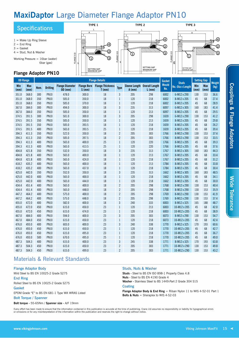
Specifications
MaxiDaptor Large Diameter Flange Adaptor PN10
Flange Adaptor PN10Od Range Flange details Gasket
Mould No.
studs No.-dia x length
setting GapWeight
(kg)Min (mm)
Max (mm) Nom. drilling Flange diameter
Od (mm)Flange Bore
s (mm)Flange Thickness
T (mm) Type sleeve length A (mm)
Overall length l (mm)
Min (mm)
Max (mm)
351.0 368.0 300 PN10 478.0 300.0 18 3 205 298 6002 6-M12 x 290 130 153 36.6351.0 368.0 350 PN10 505.0 350.0 18 1 120 218 6002 8-M12 x 205 45 68 27.4351.0 368.0 350 PN10 505.0 370.0 18 1 120 218 6002 8-M12 x 205 45 68 28.9367.0 384.0 300 PN10 494.0 300.0 18 3 235 313 6097 6-M12 x 305 160 183 41.4367.0 384.0 350 PN10 505.0 350.0 18 1 120 213 6097 8-M12 x 205 45 68 29.5374.5 391.5 300 PN10 501.0 300.0 18 3 205 298 1659 6-M12 x 290 130 153 41.2374.5 391.5 350 PN10 505.0 350.0 18 1 120 213 1659 8-M12 x 205 45 68 29.8374.5 391.5 350 PN10 505.0 393.5 18 1 120 218 1659 8-M12 x 205 45 68 26.2374.5 391.5 400 PN10 565.0 393.5 25 1 120 218 1659 8-M12 x 205 45 68 39.4394.3 411.3 350 PN10 522.0 350.0 18 2 205 303 1766 8-M12 x 290 130 153 37.4394.3 411.3 350 PN10 505.0 397.5 18 2 205 303 1766 8-M12 x 290 130 153 33.5394.3 411.3 400 PN10 565.0 400.0 25 1 120 220 1766 8-M12 x 205 45 68 39.3394.3 411.3 400 PN10 565.0 413.5 25 1 120 220 1766 8-M12 x 205 45 68 37.6404.8 421.8 350 PN10 532.0 350.0 18 3 235 313 1767 8-M12 x 305 160 183 44.3404.8 421.8 400 PN10 565.0 400.0 18 1 120 213 1767 8-M12 x 205 45 68 33.4404.8 421.8 400 PN10 565.0 424.0 18 1 120 218 1767 8-M12 x 205 45 68 31.2418.2 435.2 400 PN10 565.0 400.0 18 1 120 213 1784 8-M12 x 205 45 68 33.8418.2 435.2 400 PN10 565.0 437.0 18 1 120 218 1784 8-M12 x 205 45 68 30.4425.0 442.0 350 PN10 552.0 350.0 18 3 235 313 1662 8-M12 x 305 160 183 48.5425.0 442.0 400 PN10 565.0 400.0 18 1 120 218 1662 8-M12 x 205 45 68 34.1425.0 442.0 400 PN10 565.0 444.0 18 1 120 218 1662 8-M12 x 205 45 68 30.0434.4 451.4 400 PN10 565.0 400.0 18 2 205 298 1768 8-M12 x 290 130 153 40.4434.4 451.4 400 PN10 565.0 448.0 18 2 205 298 1768 8-M12 x 290 130 153 35.9447.2 464.2 400 PN10 575.0 400.0 18 2 205 298 1769 8-M12 x 290 130 153 41.9447.2 464.2 400 PN10 575.0 448.0 18 2 205 298 1769 8-M12 x 290 130 153 37.4455.0 472.0 400 PN10 582.0 400.0 18 3 240 333 6003 8-M12 x 325 165 188 48.7455.0 472.0 450 PN10 615.0 450.0 23 1 120 213 6003 10-M12 x 205 45 68 42.0455.0 472.0 450 PN10 615.0 474.0 23 1 120 218 6003 10-M12 x 205 45 68 38.9467.0 484.0 400 PN10 594.0 400.0 23 3 205 303 6073 8-M12 x 290 130 153 54.7467.0 484.0 450 PN10 615.0 450.0 23 1 120 218 6073 10-M12 x 205 45 68 42.4476.0 493.0 400 PN10 603.0 400.0 23 3 240 338 1770 8-M12 x 325 170 193 60.6476.0 493.0 450 PN10 615.0 450.0 23 1 120 218 1770 10-M12 x 205 45 68 42.7476.0 493.0 450 PN10 615.0 495.0 23 1 120 218 1770 10-M12 x 205 45 68 36.7476.0 493.0 500 PN10 670.0 495.0 25 1 120 218 1770 10-M12 x 205 45 68 49.0487.3 504.3 400 PN10 615.0 400.0 23 3 245 338 1771 8-M12 x 325 170 193 63.8487.3 504.3 450 PN10 615.0 450.0 23 2 205 303 1771 10-M12 x 290 130 153 49.8487.3 504.3 450 PN10 615.0 499.0 23 2 205 303 1771 10-M12 x 290 130 153 43.2
1 = Make up ring sleeve 2 = end ring 3 = Gasket 4 = stud, nut & Washer
4
2
31
Materials & Relevant Standards
Flange Adaptor BodyMild steel to Bs en 10025-2 Grade s275
End Ringrolled steel to Bs en 10025-2 Grade s275
GasketePDM Grade “e” to Bs en 681-1 type WA WrAs listed
Bolt Torque / SpannerBolt torque - 55-65nm / Spanner size - A/F 19mm
Studs, Nuts & WasherStuds - steel to Bs en iso 898-1 Property Class 4.8 Nuts - steel to Bs en 4190 Grade 4 Washer - stainless steel to Bs 1449:Part 2 Grade 304 s15
CoatingFlange Adaptor Body & End Ring = rilsan nylon 11 to Wis 4-52-01 Part 1 Bolts & Nuts = sheraplex to Wis 4-52-03
1
4
2
3
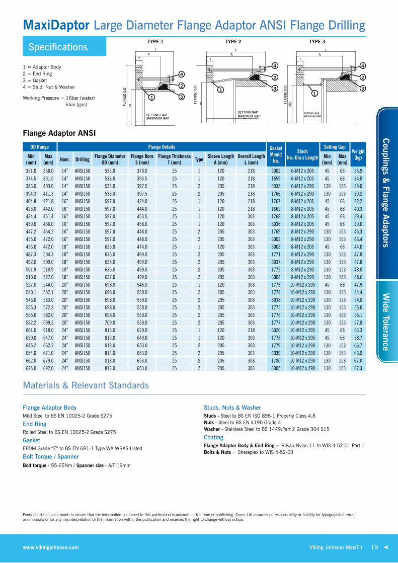
TYPE 1 TYPE 2 TYPE 3
Working Pressure = 16bar (water) 6bar (gas)
1
4
2
3
every effort has been made to ensure that the information contained in this publication is accurate at the time of publishing. Crane ltd assumes no responsibility or liability for typographical errors or omissions or for any misinterpretation of the information within the publication and reserves the right to change without notice.
15Viking Johnson MaxiFitwww.vikingjohnson.com
Couplings &
Flange Adaptors
Wide Tolerance
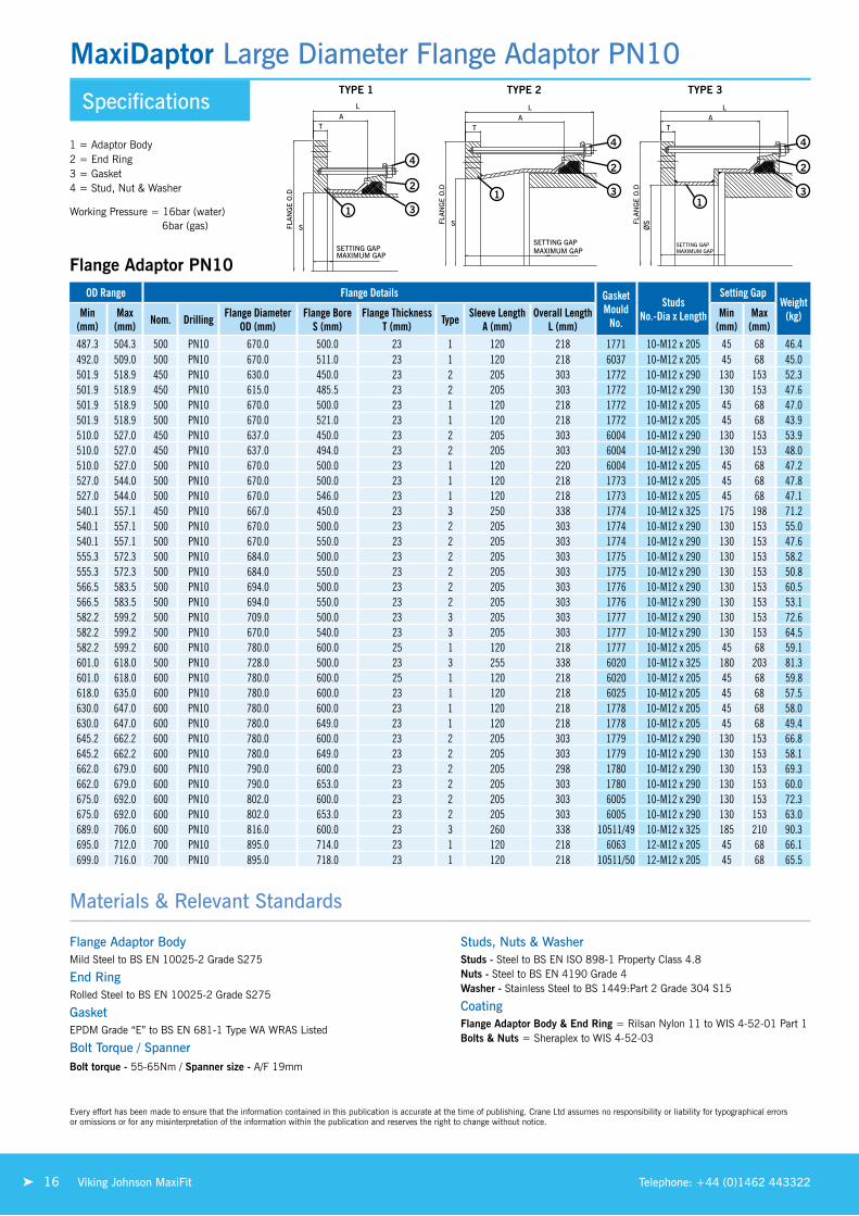
Specifications
MaxiDaptor Large Diameter Flange Adaptor PN10
Working Pressure = 16bar (water) 6bar (gas)
Od Range Flange details Gasket Mould
No.
studs No.-dia x length
setting GapWeight
(kg)Min (mm)
Max (mm) Nom. drilling Flange diameter
Od (mm)Flange Bore
s (mm)Flange Thickness
T (mm) Type sleeve length A (mm)
Overall length l (mm)
Min (mm)
Max (mm)
487.3 504.3 500 PN10 670.0 500.0 23 1 120 218 1771 10-M12 x 205 45 68 46.4492.0 509.0 500 PN10 670.0 511.0 23 1 120 218 6037 10-M12 x 205 45 68 45.0501.9 518.9 450 PN10 630.0 450.0 23 2 205 303 1772 10-M12 x 290 130 153 52.3501.9 518.9 450 PN10 615.0 485.5 23 2 205 303 1772 10-M12 x 290 130 153 47.6501.9 518.9 500 PN10 670.0 500.0 23 1 120 218 1772 10-M12 x 205 45 68 47.0501.9 518.9 500 PN10 670.0 521.0 23 1 120 218 1772 10-M12 x 205 45 68 43.9510.0 527.0 450 PN10 637.0 450.0 23 2 205 303 6004 10-M12 x 290 130 153 53.9510.0 527.0 450 PN10 637.0 494.0 23 2 205 303 6004 10-M12 x 290 130 153 48.0510.0 527.0 500 PN10 670.0 500.0 23 1 120 220 6004 10-M12 x 205 45 68 47.2527.0 544.0 500 PN10 670.0 500.0 23 1 120 218 1773 10-M12 x 205 45 68 47.8527.0 544.0 500 PN10 670.0 546.0 23 1 120 218 1773 10-M12 x 205 45 68 47.1540.1 557.1 450 PN10 667.0 450.0 23 3 250 338 1774 10-M12 x 325 175 198 71.2540.1 557.1 500 PN10 670.0 500.0 23 2 205 303 1774 10-M12 x 290 130 153 55.0540.1 557.1 500 PN10 670.0 550.0 23 2 205 303 1774 10-M12 x 290 130 153 47.6555.3 572.3 500 PN10 684.0 500.0 23 2 205 303 1775 10-M12 x 290 130 153 58.2555.3 572.3 500 PN10 684.0 550.0 23 2 205 303 1775 10-M12 x 290 130 153 50.8566.5 583.5 500 PN10 694.0 500.0 23 2 205 303 1776 10-M12 x 290 130 153 60.5566.5 583.5 500 PN10 694.0 550.0 23 2 205 303 1776 10-M12 x 290 130 153 53.1582.2 599.2 500 PN10 709.0 500.0 23 3 205 303 1777 10-M12 x 290 130 153 72.6582.2 599.2 500 PN10 670.0 540.0 23 3 205 303 1777 10-M12 x 290 130 153 64.5582.2 599.2 600 PN10 780.0 600.0 25 1 120 218 1777 10-M12 x 205 45 68 59.1601.0 618.0 500 PN10 728.0 500.0 23 3 255 338 6020 10-M12 x 325 180 203 81.3601.0 618.0 600 PN10 780.0 600.0 25 1 120 218 6020 10-M12 x 205 45 68 59.8618.0 635.0 600 PN10 780.0 600.0 23 1 120 218 6025 10-M12 x 205 45 68 57.5630.0 647.0 600 PN10 780.0 600.0 23 1 120 218 1778 10-M12 x 205 45 68 58.0630.0 647.0 600 PN10 780.0 649.0 23 1 120 218 1778 10-M12 x 205 45 68 49.4645.2 662.2 600 PN10 780.0 600.0 23 2 205 303 1779 10-M12 x 290 130 153 66.8645.2 662.2 600 PN10 780.0 649.0 23 2 205 303 1779 10-M12 x 290 130 153 58.1662.0 679.0 600 PN10 790.0 600.0 23 2 205 298 1780 10-M12 x 290 130 153 69.3662.0 679.0 600 PN10 790.0 653.0 23 2 205 303 1780 10-M12 x 290 130 153 60.0675.0 692.0 600 PN10 802.0 600.0 23 2 205 303 6005 10-M12 x 290 130 153 72.3675.0 692.0 600 PN10 802.0 653.0 23 2 205 303 6005 10-M12 x 290 130 153 63.0689.0 706.0 600 PN10 816.0 600.0 23 3 260 338 10511/49 10-M12 x 325 185 210 90.3695.0 712.0 700 PN10 895.0 714.0 23 1 120 218 6063 12-M12 x 205 45 68 66.1699.0 716.0 700 PN10 895.0 718.0 23 1 120 218 10511/50 12-M12 x 205 45 68 65.5
Flange Adaptor PN10
Materials & Relevant Standards
Flange Adaptor BodyMild steel to Bs en 10025-2 Grade s275
End Ringrolled steel to Bs en 10025-2 Grade s275
GasketePDM Grade “e” to Bs en 681-1 type WA WrAs listed
Bolt Torque / SpannerBolt torque - 55-65nm / Spanner size - A/F 19mm
Studs, Nuts & WasherStuds - steel to Bs en iso 898-1 Property Class 4.8 Nuts - steel to Bs en 4190 Grade 4 Washer - stainless steel to Bs 1449:Part 2 Grade 304 s15
CoatingFlange Adaptor Body & End Ring = rilsan nylon 11 to Wis 4-52-01 Part 1 Bolts & Nuts = sheraplex to Wis 4-52-03
1 = Adaptor Body 2 = end ring 3 = Gasket 4 = stud, nut & Washer
4
2
31
1
4
2
3
TYPE 1 TYPE 2 TYPE 3
1
4
2
3
every effort has been made to ensure that the information contained in this publication is accurate at the time of publishing. Crane ltd assumes no responsibility or liability for typographical errors or omissions or for any misinterpretation of the information within the publication and reserves the right to change without notice.
16 Viking Johnson MaxiFit Telephone: +44 (0)1462 443322

Specifications
MaxiDaptor Large Diameter Flange Adaptor PN16
Working Pressure = 16bar (water) 6bar (gas)
Flange Adaptor PN16
Od Range Flange details Gasket Mould
No.
studs No.-dia x length
setting GapWeight
(kg)Min (mm)
Max (mm) Nom. drilling Flange diameter
Od (mm)Flange Bore
s (mm)Flange Thickness
T (mm) Type sleeve length A (mm)
Overall length l (mm)
Min (mm)
Max (mm)
348.5 365.5 350 PN16 520.0 367.5 18 2 120 218 6008 8-M12 x 205 45 68 28.5351.0 368.0 300 PN16 478.0 300.0 18 3 240 333 6002 6-M12 x 325 165 188 38.5351.0 368.0 300 PN16 478.0 329.0 18 3 240 333 6002 6-M12 x 325 165 188 36.5351.0 368.0 350 PN16 520.0 370.0 18 1 120 218 6002 8-M12 x 205 45 68 28.6374.5 391.5 300 PN16 502.0 300.0 18 3 240 333 1659 6-M12 x 325 160 183 43.1374.5 391.5 350 PN16 520.0 350.0 18 1 120 218 1659 8-M12 x 205 45 68 31.0374.5 391.5 350 PN16 520.0 393.5 18 1 120 218 1659 8-M12 x 205 45 68 27.5374.5 391.5 400 PN16 580.0 393.5 25 1 120 218 1659 8-M12 x 205 45 68 41.6394.3 411.3 350 PN16 522.0 350.0 18 2 205 298 1766 8-M12 x 290 130 153 37.1394.3 411.3 350 PN16 520.0 397.5 18 2 205 303 1766 8-M12 x 290 130 153 33.1394.3 411.3 400 PN16 580.0 413.5 25 1 120 220 1766 8-M12 x 205 45 68 39.8404.8 421.8 400 PN16 580.0 400.0 18 1 120 213 1767 8-M12 x 205 45 68 34.9404.8 421.8 400 PN16 580.0 424.0 18 1 120 218 1767 8-M12 x 205 45 68 32.8418.2 435.2 400 PN16 580.0 437.0 18 1 120 218 1784 8-M12 x 205 45 68 32.0425.0 442.0 400 PN16 580.0 400.0 18 1 120 218 1662 8-M12 x 205 45 68 35.7425.0 442.0 400 PN16 580.0 444.0 18 1 120 218 1662 8-M12 x 205 45 68 31.6434.4 451.4 400 PN16 580.0 448.0 18 2 205 303 1768 8-M12 x 290 130 153 37.4447.2 464.2 400 PN16 580.0 400.0 18 2 205 303 1769 8-M12 x 290 130 153 42.2447.2 464.2 400 PN16 580.0 448.0 18 2 205 303 1769 8-M12 x 290 130 153 37.7455.0 472.0 400 PN16 582.0 400.0 18 2 205 298 6003 8-M12 x 290 130 153 42.6455.0 472.0 450 PN16 640.0 450.0 23 1 120 218 6003 10-M12 x 205 45 68 46.0455.0 472.0 450 PN16 640.0 474.0 23 1 120 218 6003 10-M12 x 205 45 68 42.8462.5 479.5 400 PN16 590.0 440.0 25 2 205 303 10511/40 8-M12 x 290 130 153 45.7467.0 484.0 450 PN16 640.0 486.0 23 1 120 218 6073 10-M12 x 205 45 68 41.6476.0 493.0 400 PN16 603.0 400.0 23 3 255 338 1770 8-M12 x 325 180 203 60.8476.0 493.0 450 PN16 640.0 495.0 23 1 120 218 1770 10-M12 x 205 45 68 40.7487.3 504.3 450 PN16 640.0 506.5 23 1 120 218 1771 10-M12 x 205 45 68 39.4487.3 504.3 500 PN16 715.0 506.5 23 1 120 218 1771 10-M12 x 205 45 68 53.2501.9 518.9 450 PN16 640.0 485.5 23 2 205 303 1772 10-M12 x 290 130 153 48.7501.9 518.9 500 PN16 715.0 500.0 23 1 120 218 1772 10-M12 x 205 45 68 54.7501.9 518.9 500 PN16 715.0 521.0 23 1 120 218 1772 10-M12 x 205 45 68 51.7510.0 527.0 450 PN16 640.0 494.0 23 2 205 303 6004 10-M12 x 290 130 153 47.9510.0 527.0 500 PN16 715.0 500.0 23 1 120 218 6004 10-M12 x 205 45 68 54.9527.0 544.0 500 PN16 715.0 500.0 23 1 120 218 1773 10-M12 x 205 45 68 55.6527.0 544.0 500 PN16 715.0 546.0 23 1 120 218 1773 10-M12 x 205 45 68 48.8540.1 557.1 500 PN16 715.0 559.0 23 1 120 218 1774 10-M12 x 205 45 68 47.2555.3 572.3 500 PN16 715.0 550.0 23 2 205 303 1775 10-M12 x 290 130 153 56.0555.3 572.3 600 PN16 840.0 649.5 25 1 120 218 1775 10-M12 x 205 45 68 62.3
Materials & Relevant Standards
Flange Adaptor BodyMild steel to Bs en 10025-2 Grade s275
End Ringrolled steel to Bs en 10025-2 Grade s275
GasketePDM Grade “e” to Bs en 681-1 type WA WrAs listed
Bolt Torque / SpannerBolt torque - 55-65nm / Spanner size - A/F 19mm
Studs, Nuts & WasherStuds - steel to Bs en iso 898-1 Property Class 4.8 Nuts - steel to Bs en 4190 Grade 4 Washer - stainless steel to Bs 1449:Part 2 Grade 304 s15
CoatingFlange Adaptor Body & End Ring = rilsan nylon 11 to Wis 4-52-01 Part 1 Bolts & Nuts = sheraplex to Wis 4-52-03
1 = Adaptor Body 2 = end ring 3 = Gasket 4 = stud, nut & Washer
4
2
31
1
4
2
3
TYPE 1 TYPE 2 TYPE 3
1
4
2
3
every effort has been made to ensure that the information contained in this publication is accurate at the time of publishing. Crane ltd assumes no responsibility or liability for typographical errors or omissions or for any misinterpretation of the information within the publication and reserves the right to change without notice.
17Viking Johnson MaxiFitwww.vikingjohnson.com
Couplings &
Flange Adaptors
Wide Tolerance

Specifications
MaxiDaptor Large Diameter Flange Adaptor PN16
Working Pressure = 16bar (water) 6bar (gas)
Flange Adaptor PN16 Continued
Od Range Flange details Gasket Mould
No.
studs No.-dia x length
setting GapWeight
(kg)Min (mm)
Max (mm) Nom. drilling Flange diameter
Od (mm)Flange Bore
s (mm)Flange Thickness
T (mm) Type sleeve length A (mm)
Overall length l (mm)
Min (mm)
Max (mm)
566.5 583.5 500 PN16 715.0 500.0 23 2 205 303 1776 10-M12 x 290 130 153 63.6566.5 583.5 500 PN16 715.0 550.0 23 2 205 303 1776 10-M12 x 290 130 153 56.2582.2 599.2 500 PN16 715.0 560.0 23 3 205 303 1777 10-M12 x 290 130 153 60.4582.2 599.2 600 PN16 840.0 601.0 25 1 120 218 1777 10-M12 x 205 45 68 72.5601.0 618.0 600 PN16 840.0 600.0 25 1 120 218 6020 10-M12 x 205 45 68 73.4601.0 618.0 600 PN16 840.0 620.0 25 1 120 218 6020 10-M12 x 205 45 68 69.7613.0 630.0 600 PN16 840.0 632.0 23 1 120 218 6019 10-M12 x 205 45 68 64.4618.0 635.0 600 PN16 840.0 637.0 23 1 120 218 6025 10-M12 x 205 45 68 63.6630.5 647.5 600 PN16 840.0 600.0 23 1 120 218 1778 10-M12 x 205 45 68 70.6630.5 647.5 600 PN16 840.0 649.5 23 1 120 218 1778 10-M12 x 205 45 68 61.8645.2 662.2 600 PN16 840.0 664.0 23 1 120 218 1779 10-M12 x 205 45 68 59.7662.0 679.0 600 PN16 840.0 681.0 23 1 120 218 1780 10-M12 x 205 45 68 57.1675.0 692.0 600 PN16 840.0 653.0 23 2 205 303 6005 10-M12 x 290 130 153 70.6
Materials & Relevant Standards
Flange Adaptor BodyMild steel to Bs en 10025-2 Grade s275
End Ringrolled steel to Bs en 10025-2 Grade s275
GasketePDM Grade “e” to Bs en 681-1 type WA WrAs listed
Bolt Torque / SpannerBolt torque - 55-65nm / Spanner size - A/F 19mm
Studs, Nuts & WasherStuds - steel to Bs en iso 898-1 Property Class 4.8 Nuts - steel to Bs en 4190 Grade 4 Washer - stainless steel to Bs 1449:Part 2 Grade 304 s15
CoatingFlange Adaptor Body & End Ring = rilsan nylon 11 to Wis 4-52-01 Part 1 Bolts & Nuts = sheraplex to Wis 4-52-03
1 = Adaptor Body 2 = end ring 3 = Gasket 4 = stud, nut & Washer
4
2
31
1
4
2
3
TYPE 1 TYPE 2 TYPE 3
1
4
2
3
every effort has been made to ensure that the information contained in this publication is accurate at the time of publishing. Crane ltd assumes no responsibility or liability for typographical errors or omissions or for any misinterpretation of the information within the publication and reserves the right to change without notice.
18 Viking Johnson MaxiFit Telephone: +44 (0)1462 443322
Specifications
MaxiDaptor Large Diameter Flange Adaptor ANSI Flange Drilling
Working Pressure = 16bar (water) 6bar (gas)
Flange Adaptor ANSI
Od Range Flange details Gasket Mould
No.
studs No.-dia x length
setting GapWeight
(kg)Min (mm)
Max (mm) Nom. drilling Flange diameter
Od (mm)Flange Bore
s (mm)Flange Thickness
T (mm) Type sleeve length A (mm)
Overall length l (mm)
Min (mm)
Max (mm)
351.0 368.0 14” ANSI150 533.0 370.0 25 1 120 218 6002 6-M12 x 205 45 68 35.9374.5 391.5 14” ANSI150 533.0 393.5 25 1 120 218 1659 6-M12 x 205 45 68 34.0386.0 403.0 14” ANSI150 533.0 397.5 25 2 205 218 6035 6-M12 x 290 130 153 39.0394.3 411.3 14” ANSI150 533.0 397.5 25 2 205 218 1766 6-M12 x 290 130 153 39.2404.8 421.8 16” ANSI150 597.0 424.0 25 1 120 218 1767 8-M12 x 205 45 68 42.2425.0 442.0 16” ANSI150 597.0 444.0 25 1 120 218 1662 8-M12 x 205 45 68 40.3434.4 451.4 16” ANSI150 597.0 453.5 25 1 120 303 1768 8-M12 x 205 45 68 39.4439.0 456.0 16” ANSI150 597.0 458.0 25 1 120 303 6036 8-M12 x 205 45 68 39.0447.2 464.2 16” ANSI150 597.0 448.0 25 2 205 303 1769 8-M12 x 290 130 153 46.3455.0 472.0 16” ANSI150 597.0 448.0 25 2 205 303 6003 8-M12 x 290 130 153 46.4455.0 472.0 18” ANSI150 635.0 474.0 25 1 120 303 6003 8-M12 x 205 45 68 44.0487.3 504.3 18” ANSI150 635.0 499.0 25 2 205 303 1771 8-M12 x 290 130 153 47.8492.0 509.0 18” ANSI150 635.0 499.0 25 2 205 303 6037 8-M12 x 290 130 153 47.8501.9 518.9 18” ANSI150 635.0 499.0 25 2 205 303 1772 8-M12 x 290 130 153 48.0510.0 527.0 18” ANSI150 637.0 499.0 25 2 205 303 6004 8-M12 x 290 130 153 48.6527.0 544.0 20” ANSI150 698.0 546.0 25 1 120 303 1773 10-M12 x 205 45 68 47.9540.1 557.1 20” ANSI150 698.0 550.0 25 2 205 303 1774 10-M12 x 290 130 153 54.4546.0 563.0 20” ANSI150 698.0 550.0 25 2 205 303 6038 10-M12 x 290 130 153 54.8555.3 572.3 20” ANSI150 698.0 550.0 25 2 205 303 1775 10-M12 x 290 130 153 55.0565.0 582.0 20” ANSI150 698.0 550.0 25 2 205 303 1776 10-M12 x 290 130 153 55.1582.2 599.2 20” ANSI150 709.0 550.0 25 2 205 303 1777 10-M12 x 290 130 153 57.8601.0 618.0 24” ANSI150 813.0 620.0 25 1 120 218 6020 10-M12 x 205 45 68 63.3630.0 647.0 24” ANSI150 813.0 649.0 25 1 120 303 1778 10-M12 x 205 45 68 58.7645.2 662.2 24” ANSI150 813.0 653.0 25 2 205 303 1779 10-M12 x 290 130 153 66.7654.0 671.0 24” ANSI150 813.0 653.0 25 2 205 303 6039 10-M12 x 290 130 153 66.9662.0 679.0 24” ANSI150 813.0 653.0 25 2 205 303 1780 10-M12 x 290 130 153 67.0675.0 692.0 24” ANSI150 813.0 653.0 25 2 205 303 6005 10-M12 x 290 130 153 67.3
Materials & Relevant Standards
Flange Adaptor BodyMild steel to Bs en 10025-2 Grade s275
End Ringrolled steel to Bs en 10025-2 Grade s275
GasketePDM Grade “e” to Bs en 681-1 type WA WrAs listed
Bolt Torque / SpannerBolt torque - 55-65nm / Spanner size - A/F 19mm
Studs, Nuts & WasherStuds - steel to Bs en iso 898-1 Property Class 4.8 Nuts - steel to Bs en 4190 Grade 4 Washer - stainless steel to Bs 1449:Part 2 Grade 304 s15
CoatingFlange Adaptor Body & End Ring = rilsan nylon 11 to Wis 4-52-01 Part 1 Bolts & Nuts = sheraplex to Wis 4-52-03
1 = Adaptor Body 2 = end ring 3 = Gasket 4 = stud, nut & Washer
4
2
31
1
4
2
3
TYPE 1 TYPE 2 TYPE 3
1
4
2
3
every effort has been made to ensure that the information contained in this publication is accurate at the time of publishing. Crane ltd assumes no responsibility or liability for typographical errors or omissions or for any misinterpretation of the information within the publication and reserves the right to change without notice.
19Viking Johnson MaxiFit www.vikingjohnson.com
Couplings &
Flange Adaptors
Wide Tolerance

United Kingdom - Canterbury
south east WaterMaxiFit Couplings - Dn500
Project MaxiFit Couplings were used
for the emergency repair of
a mains pipe in Canterbury.
it meant thousands of
customers in the city had
either no water or low
water pressure.
Client south east Water
20 Viking Johnson MaxiFit Telephone: +44 (0)1462 443322

www.vikingjohnson.com
■ Designed and manufactured under quality management systems
in accordance with BS EN ISO 9001.
■ Environmental Management System accredited to ISO 14001.
■ For full terms and conditions, please visit our website.
DR
7976
_04_
2015
46-48 WILBURY WAY HITCHIN, HERTFORDSHIRE SG4 0UD. UNITED KINGDOM
TELEPHONE: +44 (0)1462 443322 FAx: +44 (0)1462 443311 EMAIL: [email protected]
Every effort has been made to ensure that the information contained in this publication is accurate at the time of publishing. Crane Ltd assumes no responsibility or liability for typographical errors or omissions or for any misinterpretation of the information within the publication and reserves the right to change without notice.
To visit our Video Library go to:www.youtube.com/user/CraneBSU
ISO 9001 • FM 00311ISO 14001 • EMS 51874
www.cranebsu.com
P i o n e e r s i n P i P e s o l u t i o n s