universal performance curve compensator upccinfo.smithmeter.com/literature/docs/mn02011.pdf · the...
TRANSCRIPT

The Most Trusted Name In Measurement
Universal Performance Curve Compensator
UPCC
Installation/Operation
Bulletin MN02011
Issue/Rev. 0.7 (11/10)
Receipt of Equipment
When the equipment is received, the outside packing case should be checked immediately for any shipping dam-age. If the packing case has been damaged, the local carrier should be notified at once regarding his liability. Carefully remove the unit from its packing case and inspect for damaged or missing parts.
If damage has occurred during shipment or parts are missing, a written report should be submitted to the Cus-tomer Service Department, FMC Technologies Measurement Solutions, Inc., Erie, Pennsylvania 16514.
Prior to installation, the unit should be stored in its original packing case and protected from adverse weather conditions and abuse.
Caution:
This equipment generates, uses, and can radiate radio frequency energy and, if not installed and used in
accordance with this Instruction Manual, may cause interference to radio communications. It has not
been tested to comply with the limits for a Class A computing device pursuant to Subpart J of Part 15 of
FCC Rules, which are designed to provide reasonable protection against such interference when
operated in a commercial environment. Operation of this equipment in a residential area is likely to cause
interference, in which case the user, at his own expense, will be required to take whatever measures may
be required to correct the interference.
Proprietary Notice
This document contains information that is proprietary to FMC Technologies Measurement Solutions Inc. and is available solely for customer information. The information herein shall not be duplicated, used or disclosed with-out prior permission of FMC Technologies Measurement Solutions, Inc.
FMC Technologies Measurement Solutions, Inc. will not be held responsible for loss of liquid or of damage of any kind or from any cause to the person or property of others, or for loss or profit, or loss of use, or any other special, incidental, or consequential damages caused by the use or misapplication of the contents stated herein.
Table of Contents
i
Receipt of Equipment .............................................................................................................................................. 1 Proprietary Notice ................................................................................................................................................... 1
Section I – Safety Precautions ................................................................................................................................... 1 Safety Precautions .................................................................................................................................................. 1
Section II - Introduction ............................................................................................................................................... 2 Introduction ............................................................................................................................................................. 2 Operating Principle.................................................................................................................................................. 2 Hardware ................................................................................................................................................................. 2 Preamplifier ............................................................................................................................................................. 2 Meter Input Signal Selection ................................................................................................................................... 2
Meter Input Signal Switch Settings...................................................................................................................... 3 (Board assemblies with switches) ....................................................................................................................... 3 Amplifier Gain Switch Settings ............................................................................................................................ 3 (Board assemblies with switches) ....................................................................................................................... 3 Default Switch Settings ....................................................................................................................................... 3
Section III - Startup Procedures ................................................................................................................................. 4 Startup Procedures ................................................................................................................................................. 4
Installation Using EIA-485 Interface .................................................................................................................... 4 Wiring Schemes .................................................................................................................................................. 4 Number of Wires in the Communications Cable ................................................................................................. 4 RS-485 Conversion Instructions .......................................................................................................................... 4 Communication Switch Settings (Board Assemblies with Switches) .................................................................. 5 Communication Jumper Table Settings (Board assemblies with jumpers) ......................................................... 5 Programming Individual ID Number to UPCC ..................................................................................................... 5
Section IV - UPCCMate .............................................................................................................................................. 7 UPCCMate .............................................................................................................................................................. 7 Installing UPCCMate ............................................................................................................................................... 7 System Requirements ............................................................................................................................................. 7 Data Manipulation ................................................................................................................................................... 7
Section V - Menu Bar Functions ................................................................................................................................. 8 File......................................................................................................................................................................... 10
New ................................................................................................................................................................... 10 Open .................................................................................................................................................................. 10 Close ................................................................................................................................................................. 10 Exit ..................................................................................................................................................................... 10
Edit ........................................................................................................................................................................ 10 Copy .................................................................................................................................................................. 10 Configuration ..................................................................................................................................................... 10 Password ........................................................................................................................................................... 11 Access ............................................................................................................................................................... 11 Unit ID ................................................................................................................................................................ 11 Close ................................................................................................................................................................. 11 Set ..................................................................................................................................................................... 11 PC Communications .......................................................................................................................................... 11 Unit ID ................................................................................................................................................................ 11 Modbus Type ..................................................................................................................................................... 11 Baud Rate .......................................................................................................................................................... 11 Parity ................................................................................................................................................................. 12 Port .................................................................................................................................................................... 12
View ...................................................................................................................................................................... 12 Toolbar .............................................................................................................................................................. 12 Status Bar .......................................................................................................................................................... 12 Alarm List ........................................................................................................................................................... 12 Alarm Popup ...................................................................................................................................................... 12 Alarm History ..................................................................................................................................................... 12 Batch History ..................................................................................................................................................... 12 Configuration ..................................................................................................................................................... 13 Present Values .................................................................................................................................................. 13 Printer ................................................................................................................................................................ 13

Table of Contents
ii
Tools ..................................................................................................................................................................... 13 Calibration ......................................................................................................................................................... 13 4 to 20 Output .................................................................................................................................................... 13 4 to 20 Input ....................................................................................................................................................... 13 Online ................................................................................................................................................................ 14 Retry .................................................................................................................................................................. 14 Auto Connect ..................................................................................................................................................... 14 Offline ................................................................................................................................................................ 14 Control Options Screen ..................................................................................................................................... 15 Active Meter Profile ........................................................................................................................................... 15 Ticket Number ................................................................................................................................................... 15
Functions ............................................................................................................................................................... 15 Capture .............................................................................................................................................................. 16 Logoff ................................................................................................................................................................. 16 Enter Password ................................................................................................................................................. 16 Password Prompt .............................................................................................................................................. 16 Value Editor ....................................................................................................................................................... 17
Window ................................................................................................................................................................. 17 New Window ...................................................................................................................................................... 17 Cascade ............................................................................................................................................................ 17 Tile ..................................................................................................................................................................... 17 Arrange Icons .................................................................................................................................................... 17
About UPCC .......................................................................................................................................................... 18 General .............................................................................................................................................................. 19 Identification ...................................................................................................................................................... 19 Firmware Version .............................................................................................................................................. 19 Company Name................................................................................................................................................. 19 Meter Location ................................................................................................................................................... 19 Meter ID ............................................................................................................................................................. 19 Units .................................................................................................................................................................. 19 Volume .............................................................................................................................................................. 20 Time ................................................................................................................................................................... 20 Temperature ...................................................................................................................................................... 20 Density ............................................................................................................................................................... 20 Length ................................................................................................................................................................ 20 Information ......................................................................................................................................................... 20 Operating Range ............................................................................................................................................... 20 Meter Diameter (Size) ....................................................................................................................................... 21 Number of Blades .............................................................................................................................................. 21 Weights and Measures Write Protection ........................................................................................................... 21 SMI Load Printer Installed ................................................................................................................................. 21 Flow ................................................................................................................................................................... 22 Factors ............................................................................................................................................................... 23 Pulse Resolution................................................................................................................................................ 24 Maximum K-Factor % ........................................................................................................................................ 24
Multi-Viscosity Series Turbine Meters................................................................................................................... 25 Modes ................................................................................................................................................................ 25 Bidirection Mode ................................................................................................................................................ 25 Pickup Coil Connection ..................................................................................................................................... 25 Dual Pulse Security ........................................................................................................................................... 26 Pulse Output Configuration ............................................................................................................................... 26 Profiles ............................................................................................................................................................... 27 Meter Profile ...................................................................................................................................................... 27 Label .................................................................................................................................................................. 27 Constant Entry Options ..................................................................................................................................... 27 Viscosity Compensation Constants ................................................................................................................... 27 Viscosity vs. Temperature Data Points ............................................................................................................. 28 Procedure for Field Calculation of Calibration Points........................................................................................ 29 Reynolds Number .............................................................................................................................................. 29 Digital I/O Configuration .................................................................................................................................... 30
Table of Contents
iii
Output Contact Configuration ............................................................................................................................ 30 Input Contact Mode Configuration..................................................................................................................... 31 4-20 mA Configuration ...................................................................................................................................... 32 4-20 mA Outputs ............................................................................................................................................... 32 Mode .................................................................................................................................................................. 32 Low (Minimum) Engineering Value ................................................................................................................... 32 High (Maximum) Engineering Value.................................................................................................................. 32 Gain ................................................................................................................................................................... 32 Offset ................................................................................................................................................................. 33 4-20 mA Input .................................................................................................................................................... 33 Viscosity ............................................................................................................................................................ 33 Density ............................................................................................................................................................... 33 Scaling Factors .................................................................................................................................................. 34 Density Units (Kd).............................................................................................................................................. 34 Dynamic Viscosity Units (v) ............................................................................................................................... 35 Kinematic Viscosity (U) ..................................................................................................................................... 35 Viscometer Range Constants ............................................................................................................................ 36 Temperature ...................................................................................................................................................... 36 Defaults ............................................................................................................................................................. 36 Alarms ............................................................................................................................................................... 37 Input Frequency Alarm ...................................................................................................................................... 37 Temperature ...................................................................................................................................................... 37 Kinematic Viscosity ........................................................................................................................................... 37 Raw Flow ........................................................................................................................................................... 37 Meter Flow Ranges ........................................................................................................................................... 38 Compensated Flow ........................................................................................................................................... 39 4-20 mA Input .................................................................................................................................................... 39 Communications ................................................................................................................................................ 40 UPCC Setup ...................................................................................................................................................... 40
Section V - Present Value Mode .............................................................................................................................. 41 Present Value ........................................................................................................................................................ 41
Present Batch Information ................................................................................................................................. 41 Ticket Number ................................................................................................................................................... 41 Start Time .......................................................................................................................................................... 41 Current Time ...................................................................................................................................................... 41 Meter Profile ...................................................................................................................................................... 41 Raw Pulses ........................................................................................................................................................ 41 Comp x Pulse Resolution .................................................................................................................................. 42 Volume .............................................................................................................................................................. 42 Present Batch Averages .................................................................................................................................... 42 Meter ................................................................................................................................................................. 42 Non-Resettable Pulse Totals ............................................................................................................................. 43 Flow Rates ......................................................................................................................................................... 43 Instantaneous .................................................................................................................................................... 43 Batch Average ................................................................................................................................................... 43 Compensation ................................................................................................................................................... 43 Reynolds Number .............................................................................................................................................. 44 Status ................................................................................................................................................................ 44 Reduced Op Mode ............................................................................................................................................ 44 Weights and Measures ...................................................................................................................................... 44 4-20mA Outputs ................................................................................................................................................ 44 4-20 mA Input .................................................................................................................................................... 45 Digital Inputs ...................................................................................................................................................... 45 Digital Outputs ................................................................................................................................................... 45 Viscometer ......................................................................................................................................................... 45
Section VI - Security ................................................................................................................................................. 46 Security ................................................................................................................................................................. 46 Definition of Functions........................................................................................................................................... 46
Section VIII - Appendix ............................................................................................................................................. 51 Appendix A - Diagrams ......................................................................................................................................... 51

Table of Contents
iv
Appendix B - Sample Solartron Calibration Certificate ......................................................................................... 70 Appendix C - Present Values Report .................................................................................................................... 71 Appendix D - Batch History Report ....................................................................................................................... 75 Appendix E - Configuration Report ....................................................................................................................... 76 Appendix F - Alarm History Report ....................................................................................................................... 82
Section IX - Index ..................................................................................................................................................... 83 Section X - Related Publications .............................................................................................................................. 86

Section I – Safety Precautions
MN02011 Issue/Rev. 0.7 (11/10) 1
Safety Precautions
Electrical
General When an instrument is supplied in Explosion Proof / Flame Proof Instrument Housing, it is the design in-tention that the housing is to be directly coupled to a turbine meter with Explosion Proof / Flame Proof pick-up bosses. Note: If interfacing to a turbine meter that is not rated Explosion Proof / Flame Proof but rather Intrinsic Safe, then an approved In-trinsic Safe barrier must be used according to the manufacturer’s control drawing between the meter sensing device and the UPCC.
Electrical Installations (General) The maximum ambient temperature for the GP Junc-tion box w/PA-x amplifier and or UPCC / ID-2000 in-strument is 70°C; if the process temperature of the Turbine meter is expected to exceed this value then the enclosure(s) shall be remotely mounted to guar-antee the 70°C ambient is not exceeded. Note: Electrical installations should only be performed by quali-fied technicians / electricians that are trained in the techniques that apply to hazardous locations electrical equipment.
Caution: To prevent ignition of hazardous atmos-pheres, disconnect from supply circuit before open-ing, keep enclosure tightly closed when circuits are in operation.
Warning: Enclosure may contain batteries and or capacitors, to prevent ignition of hazardous atmos-
pheres, do not open unless area is known to be non-hazardous.
Electrical installations utilizing ATEX and
IEC Ex certifications
All electrical installations shall be in accordance with EN/IEC 60079-14 “Explosive atmospheres – Part 14: Electrical installations design, selection and erection” Cable entry must be in accordance to EN/IEC 60079-1 section 13. “Explosive atmospheres - Part 1: Equipment protection by flameproof enclo-sures "d" For systems utilizing cable glands, the gland and or thread adaptor must be Ex certified. The cable end must be securely installed and de-pending on the cable type be properly protected from mechanical damage. For systems utilizing conduit, an Ex certified sealing device must be used immediately at the entrance of the enclosure. Any unused entry must be suitably blocked with an Ex certified plug.
Installations following North American
Electrical Codes
All electrical installations shall be in accordance with appropriate electrical codes or with the rules pro-vided by the regulatory authority having jurisdiction. USA – NEC code, NFPA 70 Articles 500 – 515 as appropriate Canada – CEC Code, CSA 22.1 as appropriate

Section II – Introduction
2 MN02011 Issue/Rev. 0.7 (11/10)
Introduction
The Smith Meter UPCC Universal Performance
Curve Compensator is a microprocessor-based turbine meter preamplifier that has been designed to operate with the Smith line of multi-viscosity turbine meters. It is used to compensate for the viscosity of the product by either directly interfacing to a Solar-
Tron Viscometer Head, by temperature inferred viscosity correction or current proportional to viscosi-ty. It is used to convert the low voltage sinusoidal signal into a square wave pulse form that can be used to increase the transmission distance of the output.
The UPCC can be used to either increase or de-crease meter pulse resolution providing a quadrature output from a single or dual pick-up/transmitter input.
The UPCC also functions as a flow computer that provides spontaneous and average flow rates, batch and cumulative totalization, meter frequency mea-surement, and flow direction detection. The pulse output can be raw uncompensated or a high resolu-tion output and quadrature.
Operating Principle
Viscosity and flow rate are key features in determin-ing the performance of an MV Series Turbine Meter. By testing a meter over a range of viscosity‟s and flow rates, the meter factor is determined and plotted relative to the log of velocity (flow rate)/viscosity. This data is also programmed in the UPC Compen-sator at the factory. Each meter has a unique meter factor vs. velocity/viscosity characteristic curve plot-ted over a specific flow and viscosity range. In actual operation, the product viscosity must be input for each product metered. The viscosity input can be
A Constant - Manually input a known viscosity value. This is sufficient when the product vis-cosity varies little over the metered volume.
Temperature/Viscosity Input - The temperature/ viscosity input is provided at minimum and max-imum operating temperatures. The UPCC con-stantly reads the temperature and corrects for variations in viscosity. This increases the mea-surement accuracy when wide temperature vari-ations are experienced when a product is flow-ing. Up to three meter profile selections can be set up, which allows the operator to set up three separate temperature/viscosity profiles.
Viscometer Input - An analog or digital input from an on-line viscometer. This may be neces-sary where a wide range of products are han-dled and programming product viscosity is not practical.
Hardware
The CPU is a Motorola 68332 processor operating at 16 mHz. The 68332 is a 32-bit processor internally reducing to 16 bits for external connections. The Mo-torola 68332 is divided into four sections: a 68020 processor, a Time Processor Unit (TPU), internal high-speed 2K RAM, and a built-in UART. A built-in interrupt controller and watchdog timer allows the CPU to function efficiently with a minimum of addi-tional hardware. The real-time clock provides power-up reset and low power-down control.
The turbine preamplifier amplifies the two channels of the turbine sine wave signals to square wave out-put driver circuit that is capable of operating as a current sink or a current source. In addition, these square waves are passed to the CPU for the viscosi-ty-compensated output. If the CPU would fail, then the compensated output would also fail. However, the preamplifier outputs are not dependent on the CPU and can be wired to external counters for backup.
Note: The pulse amplification circuitry is not dependent on the CPU operation in any way.
Preamplifier
The turbine preamplifier section of the UPCC ampli-fies the two channels of the turbine sine wave sig-nals to a square wave output driver circuit that is ca-pable of operating as a current sink or a current source. In addition, these square waves are passed to the CPU for compensation applications.
Note: The pulse amplification circuitry is not dependent on the CPU operation in any way.
Meter Input Signal Selection
Note: Revision 9 or higher board assemblies are boards contain-ing programmable DIP switches.
Meter input signal selection is available through the dip switch settings, (see figure 6 in Appendix IX). Meter input signal selections are independent for the two meter signal inputs. Refer to the table at the end of this section for switch settings.
In addition to the selectable inputs, the revision 9 and later board assemblies supports amplifier gain selection. Refer to the table at the end of this section for more information.
Revision 8 and lower board assemblies only accept sine wave or pulse inputs which are determined by the connections on connector plug P1. The signal from the external signal source would be connected to pin 5 for channel one. The signal for channel two, if used, would be connected to pin 7. The common for the signal input would be connected to pin 2.

Section II – Introduction
MN02011 Issue/Rev. 0.7 (11/10) 3
Sine Wave
Sine Wave input selection is used when interfacing directly to the reluctance pick-up coils typically found in liquid turbine meters.
Pulse
Pulse input selection is used when interfacing to a pre-amplified square wave signal, i.e., if the UPCC is mounted in a remote location from the turbine meter. Typically the turbine meter will utilize a pre-amplifier such as the Smith Meter PA-6 in order to drive the signal long distances. The amplified meter pulse signals from the remote turbine meter are then sup-plied to the UPCC.
Meter Input Signal Switch Settings (Board assemblies with switches)
Input
Selection
Pos
1
Pos
2
Pos
3
Pos
4
Pos
5
Pos
6
Reluctance Pick-up
OFF ON OFF ON OFF OFF
Contact or Open Collector
ON ON OFF ON OFF ON
Active Sensor
OFF ON OFF ON OFF ON
Note: Channel A selection switch is SW1 Channel B selection switch is SW2
Amplifier Gain Switch Settings (Board assemblies with switches)
Ga
in
Se
lec
tion
No
min
al T
rip
Vo
ltag
e (m
V)*
Inp
ut T
yp
e
Po
sitio
n
7
Po
sitio
n
8
Po
sitio
n
9
Po
sitio
n
10
X 100 20 Reluctance Pick-up Coil
ON OFF OFF OFF
X50 40 Reluctance Pick-up Coil
OFF ON ON OFF
X25 70 Reluctance Pick-up Coil
OFF OFF ON ON
X18 110 Reluctance Pick-up Coil
OFF OFF OFF ON
X10 200
Active Sensor, or Open Collector
OFF OFF OFF OFF
* Hysterisis is approximately 10% of nominal values
Note: Channel A selection switch is SW1 Channel B selection switch is SW2
Default Switch Settings
Position 1 2 3 4 5 6 7 8
SW3 On Off Off On Off On X X
SW4 Off Off Off Off X X X X
SW5 On Off On Off On Off X X
SW6 See Communications Switch Settings on Page 6 On Off
Note: These are factory default settings. Changing the settings for Switches 3 through 5 will result in faulty operation.
Note: See Communications section for Switch 6 settings.

Section III – Startup Procedures
MN02011 Issue/Rev. 0.7 (11/10) 4
Startup Procedures
After the mounting is complete, bring the wires from the pickup coil A to turbine input #1 plus (pin 6) and turbine input #1 minus (pin 5). If dual pickups are de-sired, bring pickup coil B wires to turbine #2 plus (pin8) and turbine #2 minus (pin 7).
Note: The Smith Meter MVTM is a unidirectional meter.
1. The UPCC is also capable of processing a square wave input from either a separate pre amplifier or an external transmitter. The signal from the external signal source would be con-nected to pin 5 for channel 1 and the signal for channel two if used would be connected to pin 7, the common for the signal input will be connected to pin 2.
2. The UPCC requires one power source to operate the unit. The incoming power (12-24 Vdc) is wired into terminals 1 and 2 on the 16-position wiring connector (P1). The positive terminal is wired from the power supply to terminal 1 and the negative terminal is wired from the power supply to terminal 2.
3. The daughter board requires a jumper wire from pin 1 of the 16-position connector (P1) to pin 1 of connector J1 and from pin 2 of the 16-position connector to pin 2 of J1. Wire size should not ex-
ceed 20 AWG. For operation below -4 F (-20 C), the input voltage must be 24 Vdc.
4. When connecting more than one UPCC to a common power supply, the inrush current of 1.5A
for 8 MS at -40 F (-40 C) for each unit on startup must be used in determining the power supply required. Normal run current is less than 250 mA at 24 Vdc per unit.
5. Connect turbine square wave output to the host device, i.e., flow computer or RTU. Two outputs are available (see Figure 4). The first one is des-ignated as pulse output #1 and the second one is pulse output #2. The return is common with tur-bine power return. Both outputs are active if both coils are connected. If only one pickup coil is connected, then only one pulse output is pro-vided.
Note: Bi-directional meters requiring separate outputs for forward and reverse are available by programming the switch outputs in conjunction with the turbine output. The user must assign two switch outputs. One is assigned for the forward active high and the other is assigned for the forward active low. The user must route the pulse output through the switch output that is controlled by the switch setting.
Communications to the UPCC can be either through EIA-232 (fac-tory default) or EIA-485. If multiple UPCCs are to communicate with one personal computer or another type of communicating de-vice, EIA-485 communications must be used. The software pro-vided on the supplied disk is utilized with a Windows-based per-sonal computer to set up and monitor the UPCC. Recommended communication cable for the UPCC is Belden 9533 (24 Awg, 3 wires with shield or equivalent).
Installation Using EIA-485 Interface
This section of the manual is designed to provide de-tailed instructions for the installation of multiple UPCCs using the EIA-485 Interface and a daisy chain wiring scheme.
Wiring Schemes
Physically, the UPCC supports two different wiring schemes for installation:
1. Point to Point. (EIA-232 or EIA-485) This is where one UPCC and a single computer are di-rectly connected to each other via communica-tions wires.
2. Daisy Chain. (EIA-485 Only) This is where many UPCCs and a single computer are connected via half duplex EIA-485 interface where the commu-nications wires are connected in series, that is, one UPCC is connected to the next until the computer is reached. This section of the manual assumes that the Daisy Chain scheme is being used.
Number of Wires in the Communications
Cable
Each of the wiring schemes described above will support EIA-485 (2-wire half duplex) or EIA-232 (3 wire, Tx, Rx and Common). Utilizing the EIA-232 or EIA-485 communication scheme is dependent on the number of UPCCs that will be on the communication line. Remember, for EIA-232 only one unit can be on the communication line. The length of the cable run and the type of wire used are important considera-tions for long cable runs. Recommended communica-tion cable for the UPCC is Belden 9533 (24 AWG, 3-wire with shield) or equivalent.
RS-485 Conversion Instructions
The following instructions cover the converting of the UPCC from the factory default RS-232 setting to the two-wire half-duplex RS-485 interface.
The UPCC are shipped from the factory ready for op-eration using the RS-232 interface. To convert to RS-485 please refer to the following tables depending on your UPCC hardware switches and jumpers. The UPCC‟s microprocessor reads the settings on power up only; any changes to the settings while the unit is powered will result in a malfunction.
Note: These setting changes should be made prior to field installa-tion. If the changes must be made in the field while the UPCC is mounted on a turbine meter, be sure to remove power from the UPCC and get the proper work permits before attempting any of these changes.
Note: The RS-485 Termination Resistor is only used if the applica-tion requires it on one UPCC, the last one in the daisy chain.

Section III – Startup Procedures
MN02011 Issue/Rev. 0.7 (11/10) 5
Communication Switch Settings (Board assemblies with switches)
Switch 6
Positions
(On)
Switch 6
Positions
(Off)
Communications Type
2, 4 1, 3, 5, 6 RS-232 Communication
1, 3, 5 2, 4, 6 RS-485 Communication
1, 3, 5, 6 2, 4 RS-485 communications with termination resistor enabled on last unit in communications loop
Communication Jumper Table Settings (Board assemblies with jumpers)
Jumper
Position
RS-485
Communication
RS-232
Communication
JP1 Installed Removed
JP8 RS-485 termination resistor to be installed
on last unit in communications loop
Removed
JP9 Pos 1 to 2 RS-485 Communications
Pos 2 to 3 RS-232 Communications
JP10 Pos 1 to 2 RS-485 Communications
Pos 2 to 3 RS-232 Communications
Programming Individual ID Number to UPCC
If more than one UPCC is going to be placed on the RS-485 communication line each unit will need to be programmed individually with a unique ID number. (Only one unit can be placed on the communication line until a specific ID number is programmed.) It would be better to perform this operation on the bench prior to field installation.
Note: RS-485 communications is performance limited by the PC, i.e., the slower the machine the longer the updates will take to ap-pear on the Present Values screen. A typical screen update rate for RS-232 communications is around two seconds. For RS-485 communications the Present Values screen updates range from three seconds to over ten seconds depending on the amount of memory, the video card and the processor speed of the PC.
1. The following will be needed to program the indi-vidual ID number.
a) DC power supply, this can be either 12Vdc or 24 Vdc. Connect the power supply to the UPCC.
b) Personal computer loaded with the UPCC Windows program. This software is shipped with every UPCC as described in this UPCC Installation/Operation Manual.
c) An asynchronous EIA-485 half duplex to EIA-
232 interface converter (Smith P/N 645850-4-
03 or equivalent) is required for connecting
the EIA-485 communications cable into the
personal computer‟s serial port, which is EIA-
232.
d) EIA-232 Modem cable (Smith P/N 644606-4-60) for connecting the EIA-485 interface con-verter to the PC. The EIA-232 cable has a 25-pin male connector (converter interface) and a 9-pin female connector for the serial port con-nection on the personal computer.
2. Connect the EIA-232 interface cable into the EIA-485 to EIA-232 converter, wire the EIA-485 from the converter to the UPCC. Refer to Figure 12 for exact cable wiring instructions to the UPCC.
3. Start UPCCMate by double clicking on the UPCCMate icon. The first window to be displayed will be the “Enter Password” window, as shown below.
4. Press cancel, then select “File” from the top tool bar as shown.
5. Select “Open,” then click on the “OK” button to select the default.mtr file.
6. This operation will load the default.mtr file para-meters into the UPCCMate. The default parame-ters are used to establish communications with the UPCC on startup.
7. To establish communications, select “Tools” and then “On-line.”

Section III – Startup Procedures
MN02011 Issue/Rev. 0.7 (11/10) 6
8. Once on-line, the status bar on the bottom of the UPCCMate window will display “On-line.” to change the unit ID number, select “Edit” and then “Configuration” from the top menu bar. An alter-nate method is to select the “Toolbar” button be-low “Edit.”
9. This will bring up the configuration menu file tabs. Select the communication file tab. The screen will be displayed as shown below.
10. To change the Unit ID number, type a new num-ber in the highlighted box, then press “Upload.” Another window will appear, prompting the user to press “Upload.” After the “Upload” button is pressed, the upload procedure will begin. The UPCCMate will then display a warning window as shown below.
11. Press the “OK” button for the new ID number to be set. The UPCC is now programmed with a unique ID number. Do not try to program another unit with the same number, as this will cause a system malfunction when all units are on the same communications line.
12. Disconnect the unit and reconnect the next unit to be programmed with an ID number.
13. From the “Run Mode” screen, select “File Open” as shown in the beginning of this section. Repeat all steps until all UPCCs have been programmed.
14. To exit the program, select “File” then “Exit” from the “Run Mode” screen.
The factory default settings are shown in the PC communications settings screen, which is accessed by selecting “Edit” then “PC Communications Set-tings.”
This menu is used to change any PC parameters, such as the Comm Port. For further information, please refer to the “Toolbar Functions (Edit)” section of this manual.
Item Entry Description
Unit ID Number 255 (where “xxx” is 1 to 255 -- Enter the unique ID number of your choice)
Modbus Type ASCII RTU ASCII
Parity Odd None Odd Even
Baud Rate 19200 1200 2400 4800 9600 19200
RTS Delay 0
Note: Entries shown are factory defaults.
Note: all parameters must be identical for each UPCC that will be placed on the daisy chain, except for the unique ID number.
The number of UPCCs on one daisy chain is limited to thirty-two (32).
Note: For the fastest reliable connection utilizing RS-485 it is rec-ommended that the Modbus type be set to RTU, no parity and a RTS delay of 50 mS or greater. A RTS setting lower than 50 mS can result in loss of communications when in RS-485 mode.

Section IV – UPCCMate
MN02011 Issue/Rev. 0.7 (11/10) 7
UPCCMate
UPCCMate is a Windows user interface program designed to interface with the UPCC. The UPCCMate utilizes the Modbus communication pro-tocol. A listing of the Modbus registers can be found in Communications Manual MN02012. UPCCMate was written for customers who do not wish to have custom applications written to run on custom sys-tems. UPCCMate is the fastest and easiest method for communicating with the UPCC instrument.
For customers who desire custom applications, the Modbus table in Communications Manual MN02012 will aid in the generation of custom programs to communicate with PLC type devices or any other type of equipment that utilizes the Modbus protocol.
Installing UPCCMate
UPCCMate is supplied on a 3.5” 1.44MB floppy disks P/N 235635-1-02.
The UPCCMate will not run directly from the floppy disks. The program must be installed onto your computer‟s hard drive utilizing the built-in setup pro-gram.
Windows 95 users will install UPCCMate by placing disk 1 into an available 3.5” HD drive, then selecting “Run” from the taskbar. Type a:/setup.exe in the command line, then choose “OK.” The installation
program will then prompt the user for information on where to place the program files on your hard drive. The installation program will prompt the user to in-sert disk 2 to finish the installation. The installation program will create a UPCCMate program group on your taskbar. Within this group there will be a UPCCMate icon. When the icon is selected, the ap-plication will begin.
Only one instance of UPCCMate can be opened on your desktop at a time.
System Requirements
The minimum system requirements for UPCCMate are the same requirements to run Microsoft Win-dows. Please refer to the Microsoft Windows manual for complete specifications.
Data Manipulation
All configuration parameters entered into the UPCCMate must be saved to a file for future use and be uploaded to the UPCC memory. It is manda-tory that any change be uploaded. It is highly rec-ommended that a file be created and saved to disk. Failure to do either of the steps after a parameter change has been made will result in the following messages.

Section V – Menu Bar Functions
MN02011 Issue/Rev. 0.7 (11/10) 8
If the user is working on-line:
If the user is working off-line:
Choosing “No” for the above messages will result in the changes being lost.
Note: If the operator is working on-line and changes have been uploaded to the UPCC (sent from PC to UPCC), the UPCCMate will return to the “Run” screen. To ensure that the information is stored for future use, it is recommended that a .mtr file be gener-ated and stored to disk on the PC. The following section explains
how to do this. It is very important to save the .mtr file to disk whenever any change is made to keep it current. Also, any changes must be uploaded to the UPCC to take effect. After an upload is performed, it is a good idea to perform a download (re-trieve files from UPCC to the PC) to verify the data.
If the user is configuring the UPCCMate off-site (working off-line) the .mtr file that was created by the user must be uploaded to the appropriate UPCC when the user makes a connection (on-line).
All Configuration File Tabs have the bottom toolbar with the following buttons: Save, Load, Upload, Down-load, OK, Cancel, and Help. (See figure below.)
Section V – Menu Bar Functions
MN02011 Issue/Rev. 0.7 (11/10) 9
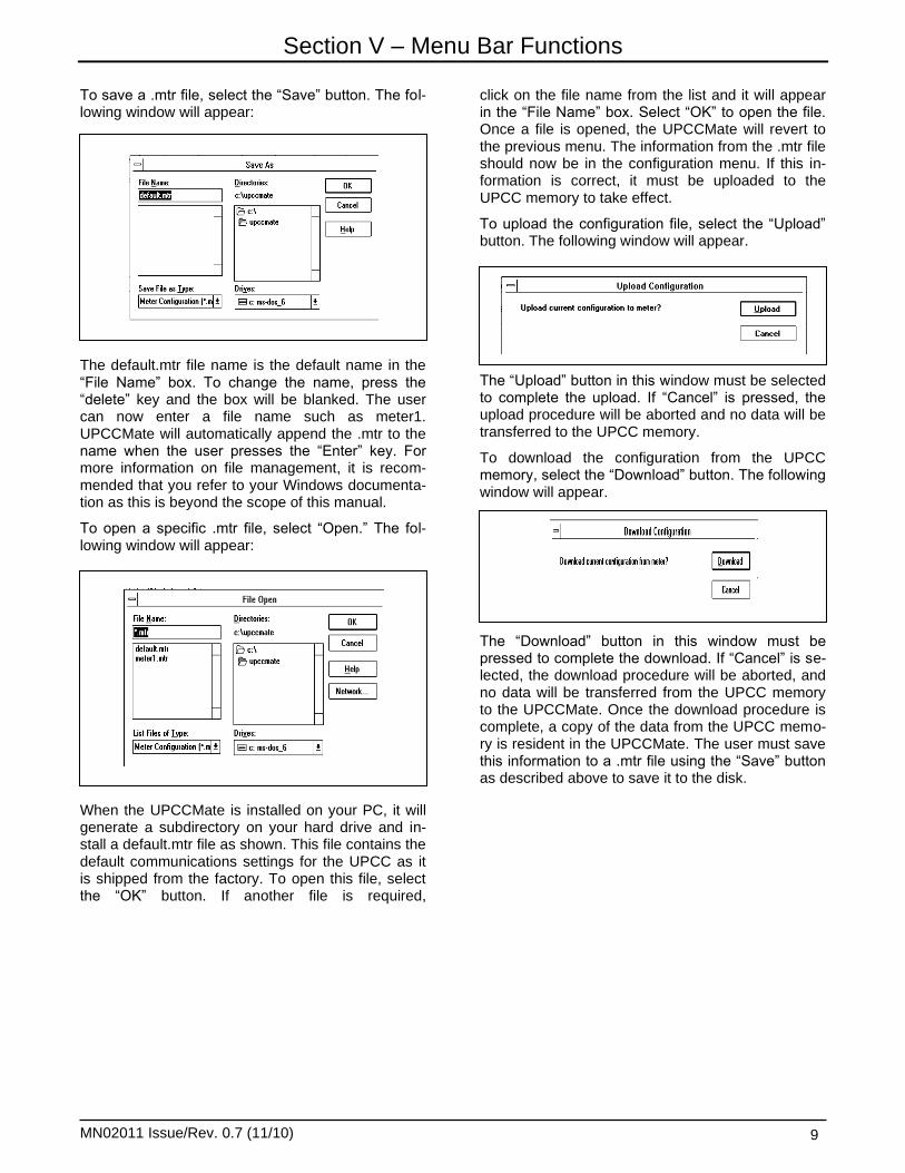
To save a .mtr file, select the “Save” button. The fol-lowing window will appear:
The default.mtr file name is the default name in the “File Name” box. To change the name, press the “delete” key and the box will be blanked. The user can now enter a file name such as meter1. UPCCMate will automatically append the .mtr to the name when the user presses the “Enter” key. For more information on file management, it is recom-mended that you refer to your Windows documenta-tion as this is beyond the scope of this manual.
To open a specific .mtr file, select “Open.” The fol-lowing window will appear:
When the UPCCMate is installed on your PC, it will generate a subdirectory on your hard drive and in-stall a default.mtr file as shown. This file contains the default communications settings for the UPCC as it is shipped from the factory. To open this file, select the “OK” button. If another file is required,
click on the file name from the list and it will appear in the “File Name” box. Select “OK” to open the file. Once a file is opened, the UPCCMate will revert to the previous menu. The information from the .mtr file should now be in the configuration menu. If this in-formation is correct, it must be uploaded to the UPCC memory to take effect.
To upload the configuration file, select the “Upload” button. The following window will appear.
The “Upload” button in this window must be selected to complete the upload. If “Cancel” is pressed, the upload procedure will be aborted and no data will be transferred to the UPCC memory.
To download the configuration from the UPCC memory, select the “Download” button. The following window will appear.
The “Download” button in this window must be pressed to complete the download. If “Cancel” is se-lected, the download procedure will be aborted, and no data will be transferred from the UPCC memory to the UPCCMate. Once the download procedure is complete, a copy of the data from the UPCC memo-ry is resident in the UPCCMate. The user must save this information to a .mtr file using the “Save” button as described above to save it to the disk.

Section V – Menu Bar Functions
MN02011 Issue/Rev. 0.7 (11/10) 10
File
“File” is the first item on the menu bar of the UPCC. It can be activated by moving the cursor to it with the mouse and clicking the left-hand button, or by press-ing “ALT F” on the keyboard. Under the File heading, the following functions can be performed: New, Open, Close, and Exit.
New
This function is used to create a new configuration file (xxx.mtr). “New” is the first option on the pull-down menu under “File” at the top left of the screen. The meter configuration file is used to store all of the programming information for a particular UPCC. When multiple UPCCs are used, this file is also used to establish communications with a specific UPCC that is connected on the communications line as de-scribed in the next section.
Open
This function is used to open a specific file that has been created and stored on a disk file. “Open” is the second option on the pulldown menu under “File” at the top left of the screen. By selecting a specific file, the user can access the UPCC that is associated with that file. Upon opening the file, the “Present Value” screen window for the UPCC selected will be displayed.
Note: The Windows 3.1x version will only support one UPCC “Present Value” screen windows at a time.
Close
This function will close the file and “Present Value” window, and end communications with the UPCC that was associated with the file. “Close” is the third option on the pulldown menu under “File” at the top left of the screen.
Exit
This function will terminate the program. The next time the program is started, the last “Present Value” screen to be opened will be the default. “Exit” is at the bottom of the pulldown menu under “File” at the top left of the screen.
Edit
“Edit” is the second item from the left on the menu bar of the UPCC. It can be activated by moving the cursor to it with the mouse and clicking the left-hand button or by pressing “ALT E” on the keyboard. Un-der the Edit heading, the following functions can be performed: Copy, Configuration, Password, and PC Communication Settings.
Copy
This function is used to copy selected text into the Windows clipboard. This function is only available from the “Edit” pulldown menu for the following se-lections: Alarm History, Batch History, Configuration, and Present Values. The “Edit” menu is the second selection from the left on the toolbar at the top of the screen. The shortcut for the “Copy” command is the first icon (two sheets of paper) on the toolbar line. The normal attribute mode for either the “Copy” command or the “Copy” icon is dimmed until an area of text is highlighted using the mouse. The attribute will then be displayed as normal.
Once the command is issued, the area of highlighted text is placed into the Windows clipboard and stored until overwritten.
Configuration
The configuration screens are used to set up a number of program parameters. The screens are broken down into eight different types of information, with each section marked by a file tab: General, Flow, Profiles, Digital I/O, 4 to 20 I/O, Viscosity, Alarms, and Communications. See Section V Confi-guration Menu for details.

Section V – Menu Bar Functions
MN02011 Issue/Rev. 0.7 (11/10) 11
Password
This screen is used to set all passwords for data en-try screens that are protected. See Security Section VII of this manual for further details.
Password Editor
To gain access to the Password editor, select “Edit” from the top tool bar, then select “Password” from the pulldown menu.
Note: ALT “E” will activate the Edit pulldown menu. From the Edit menu, press “P.”
The password editor is used to set up passwords for different areas of the UPCC. If a password is set up for a specific area of the UPCC, that area will not be able to be changed unless the password is entered prior to the change. This subject is covered in detail in the “Security” section of the manual. The screen is segmented into five areas: Access, Password, Con-firmation, Close, and Set.
Access
The Access window is used to choose the segment of the UPCC that is to be protected by the password that is entered in the next window. The areas of the UPCC that can be password-protected are: Parameter Entry Switch Output Status Input Security Codes Date and Time End Batch Reset Cumulative Totalizer Weights and Measures Supervisor
Password
The password can be made up of a combination of alphanumeric characters. The password has a max-imum length of six characters.
Confirm
The same word or designation must be entered in the Confirm window as was entered in the Password window. This window is used to confirm the pass-word entered above.
Close
The Close button closes the screen and returns to the run mode screen. If the Close button is clicked on before the Set button is, the password that was entered will be ignored.
Note: The last password that was entered will remain in effect un-til either the program is exited or the password is logged off by se-lecting the Tools Logoff pulldown.
Set
The Set button is used to set the password in the UPCC. If the set button is not pressed, the password will not be activated and will be lost.
PC Communications
This pulldown menu is used to change the parame-ters of the PC communications settings only. For in-formation on changing the communications of the UPCC, please refer to the Menu Bar Functions (Configuration) Communications section of this ma-nual.
Note: The settings in this window must match the UPCC commu-nications parameters. If not, UPCCMate will issue a warning mes-sage, and the user may be forced to run Auto Connect to correct the settings. The Unit ID number must be set by the user to match the UPCC settings for the UPCC that is to be communicated with if a .mtr file is not being used to open communications with a C. UPC
Unit ID
The Unit ID function is used to direct UPCCMate to a particular UPCC address on the communication line after all UPCCs on the communication line have had their individual identification numbers set. The valid range for this function is 1 to 255.
Note: The factory default ID setting is 255.
Modbus Type
This function allows the user a selection between RTU or ASCII communication protocols.
Note: RTU is the fastest of the two communication protocols.
Baud Rate

Section V – Menu Bar Functions
MN02011 Issue/Rev. 0.7 (11/10) 12
This selection will change the baud rate setting of the PC. Choices are 1200, 2400, 4800, 9600, and 19,200.
Parity
This selection will change the parity settings for the PC depending on the Modbus type selected. Valid choices are “None” for RTU and “Odd” or “Even” for ASCII.
Note: The UPCCMate will automatically set Modbus, baud rate, and parity parameters to match the information for the UPCC if a .mtr file is used to set up the UPCCMate. For example, the user in a previous session created a METER1.mtr file. If the user wants to establish communications with that particular UPCC, the user would choose “File Open,” then select the METER1.mtr file. If the PC communications parameters differed from the UPCC commu-nication parameters stored in the file, the UPCCMate would display a warning message stating that it was changing the PC communi-cations parameter to match the parameters in the file.
Port
The port setting allows the user to select the commu-nications port to be used on the PC. Valid choices are Com 1 through Com 4.
View
“View” is the third item from the left on the menu bar of the UPCC. It can be activated by moving the cur-sor to it with the mouse and clicking the left-hand but-ton or by pressing “ALT V” on the keyboard. Under the View heading, the following can be viewed: Tool-bar, Status Bar, Alarm List, Alarm Popup, Alarm His-tory, Batch History, Configuration, and Present Val-ues.
Toolbar
This function controls the presence of the tool bar, ei-ther displayed or hidden. To activate, click on the word “Toolbar” in the pull-down menu. A check mark indicates an active toolbar. Absence of the check mark indicates a deactivated tool bar.
Status Bar
This function controls the presence of the status bar, either displayed or hidden. To activate, click on the words “Status Bar” in the pull-down menu. A check mark indicates an active status bar. Absence of the check mark indicates a deactivated status bar. The status bar is used to display information on the bot-tom line of the UPCCMate desktop. Items monitored in order include concise description of functions, on-line/off-line, alarms present/no alarms, caps lock, number lock, and scroll lock.
Alarm List
This function controls the presence of the alarm list that is displayed as a side bar to the right of the Present Value screen, either displayed or hidden. The related toolbar icon is the “Bell with Glasses.” Alarm information displayed is the same as the alarm popup, except it is formatted as a side bar.
Alarm Popup
This function controls the presence of the alarm po-pup list that is displayed in the desktop area of the Present Value screen, either displayed or hidden. The related toolbar icon is the “Bell.” Alarm informa-tion is displayed as shown. If the alarm is a latched alarm, a check mark will appear in the box under the “L” column. To clear a latched alarm, the user must enter the Control Option menu and press the Clear Latched Alarms button. If the alarm is an instantane-ous alarm, a check mark will appear under the “I” column. When the alarm condition is remedied, the alarm status will clear automatically.
The following functions are used to access reports that can be printed or saved to a print file.
Alarm History
The Alarm History Report tracks the alarm history of the previous 50 alarm conditions of the UPCC that is displayed in the active Present Value screen.
Batch History
The Batch History Report tracks the batch history of the previous 50 batches of the UPCC that is dis-played in the active Present Value screen. Batches can be controlled either by operator intervention us-ing UPCCMate from the Control Options menu, or by an external switch contact input. For further informa-tion on controlling batches, refer to the Control Op-tions menu and the Digital I/O section of this manual.

Section V – Menu Bar Functions
MN02011 Issue/Rev. 0.7 (11/10) 13
Configuration
The Configuration report lists all parameters that are programmed into the UPCC that is displayed in the active Present Value screen.
Present Values
The Present Values report lists all parameters that are displayed from the UPCC in the active Present Value screen.
Printer
The Printer icon on the toolbar or the pull-down menu items is used to control the printer for the printing of the above reports. This is a standard Windows func-tion and is beyond the scope of this manual. For fur-ther information on controlling the system printer, please refer to your Windows documentation or use the “Help” button for on-line help.
Tools
“Tools” is the fourth item from the left on the menu bar of the UPCC. It can be activated by moving the cursor to it with the mouse and clicking the left-hand button or by pressing “ALT T” on the keyboard. Under the Tools heading, the following functions can be ac-complished: Calibration, On-line, Control, Dial, Log-off, Enter Password, Password Prompt, and Value Editor.
Calibration
By clicking on the Configuration function or by press-ing “ALT C” on the keyboard, the configuration choic-es of 4 to 20 Output 1, 4 to 20 Output 2, and 4 to 20 Input will be displayed. From this menu, the 4 to 20 outputs or input can be calibrated.
4 to 20 Output
The 4-20 output calibration screens are used to cali-brate the two 4-20mA outputs on the UPCC. The 4-20 calibration screens are located on the Tools menu under Calibration. By clicking on 4-20 Output 1, the screen for calibrating output will be displayed. The window on the top of the screen will provide instruc-tions for the calibration process. When the screen is
displayed, the following steps are used to calibrate the output:
1. The message “Please enter the desired low cur-rent output value...” is displayed at the top of the screen. ENTER the set point value that is re-quired to be calibrated (i.e., 4.00mA).
2. Click on the „NEXT‟ button at the bottom of the screen.
3. The message “Please enter actual measured value...” is displayed at the top of the screen. From the current measuring device, enter the measured value (i.e., 4.01 mA).
4. Click on the „NEXT‟ button at the bottom of the screen.
5. The message “Please enter the desired high cur-
rent output value.” Enter the setpoint value that is
required to be calibrated (i.e., 20.00 mA).
6. Click on the „NEXT‟ button at the bottom of the
screen.
7. The message “Please enter actual measured
value...” is displayed at the top of the screen.
From the current measuring device, enter the
measured value (i.e., 19.997 mA).
8. Click on the „NEXT‟ button at the bottom of the
screen.
9. The UPCC program will calculate the offset and
gain and display them in the results windows on
the screen (Offset 1.3250e-002, Gain 0.9992).
To accept these values and transfer them to the 4-20
mA output configuration screen, click on the „FINISH‟
button at the bottom of the screen.
If both 4-20 mA outputs are being used, the proce-dure will have to be repeated for the second output.
4 to 20 Input
The 4-20 input calibration screen is used to calibrate the 4-20 mA input on the UPCC. The 4-20 calibration screen is located on the “Tools” menu under “Calibra-

Section V – Menu Bar Functions
MN02011 Issue/Rev. 0.7 (11/10) 14
tion.” By clicking on the 4 to 20 Input, the screen for calibrating the input will be displayed. The window at the top of the screen will provide instructions for the calibration process. When the screen is displayed, the following steps are used to calibrate the output:
1. The message “Please enter the value of the ap-plied low current...” is displayed at the top of the screen. Enter the set point value that is required to be calibrated, i.e., 4.00 mA.
2. Click on the “NEXT” button at the bottom of the screen.
3. The message “Please enter the value of the ap-plied high current...” is displayed at the top of the screen. ENTER the set point value that is re-quired to be calibrated, i.e., 20.00 mA.
4. Click on the “NEXT” button at the bottom of the screen.
5. The message “Please enter the value of the ap-plied high current...” is displayed at the top of the screen. Enter the set point value that is required to be calibrated, i.e., 20.00 mA.
6. Click on the “NEXT” button at the bottom of the screen.
7. The message “Please enter actual measured value…” is displayed at the top of the screen. From the current measuring device, enter the measured value (i.e., 19.997 mA).
8. Click on the “NEXT” button at the bottom of the screen.
9. The UPCC program will calculate the offset and gain and display them in the results window on the screen (Offset 1.3250e-002, Gain 0.9992).
To accept these values and transfer them to the 4-20 mA input configuration screen, click on the “FINISH” button at the bottom of the screen.
If both 4-20 mA outputs are being used, the proce-dure will have to be repeated for the second output.
Online
This function is used to control the UPCCMate com-munications with a UPCC. The choices are on-line or off-line. The On-line selection will place a check mark next to the On-line pulldown text. To use the UPCCMate in the off-line mode, click on the On-line pulldown selection and the check mark will be re-moved. Off-line is used to set parameters in the UPCCMate if there is no UPCC with which to com-municate. Remember, any changes made must be saved in a .mtr file.
On-line is automatic if a .mtr file is used to establish communications with a UPCC given that the UPCC is operational. If the UPCCMate encounters a commu-nication problem (i.e., wrong communications set-tings, or the UPCC is disconnected from the commu-nications line), the following message will be dis-played:
Retry
Retry will try the connection again. If the problem is known and corrected, use this option.
Auto Connect
Auto Connect will automatically step through all valid combinations of communications parameters (baud rate, Modbus type, and parity) until a response is de-tected from a UPCC.
Use this command if the user doesn‟t remember all of the communications parameters. Auto Connect can be used to identify the communication parameters as described in the following note.
Note: Auto Connect will read the settings from a working UPCC on the communications line; however, it is up to the user to enter the correct unit ID number in the PC communications menu. If the ID number is not known, enter an ID number of zero. Enter the Tools pulldown menu, then press On-line. After a brief time, the ID num-ber will be displayed in the header information on the top of the user interface window. UPCCMate may issue another Connection Failed warning. The user must enter the ID number in the PC communications menu (from the Edit pulldown list) and press OK. All communications should then be restored. If more than one UPCC is on the communications line, Auto Connect will randomly select a UPCC with which to communicate.
Offline Offline will allow the user to work without a UPCC to perform configuration setups.

Section V – Menu Bar Functions
MN02011 Issue/Rev. 0.7 (11/10) 15
Control Options Screen
The Control Options screen is used to control and change the meter profile, ticket number, and end of a batch; clear latched alarms; reset cumulative totaliz-ers; and update the UPCC system clock from the PC. Select the Control Options screen by clicking on Con-trol.
Changes are made to the system through the screen by the following steps:
1. In the case of the active profile or the ticket num-ber, either choose the active profile required or enter the new ticket number in the window.
2. Select the “Change Active Profile” or “Change Ticket Number” bar.
3. Close the screen by clicking on the “Close” but-ton at the bottom of the screen. If the screen is closed using any other method, the changes will not be made to the system.
For the remainder of the functions on the screen, simply choose the function by selecting the bar, then close the screen as described in Step 3 above.
Active Meter Profile
This window is used to view and/or select the active meter profile to be used by the UPCC. Up to three profiles can be set up in the unit. Using the pick list in the active profile window, choose the profile required for the application. (Note: The profiles are set up on the profile configuration screen.) Once the profile is selected, click on or select the “Change Active Pro-file” bar. This will activate the change. When the screen is closed using the “Close” button at the bot-tom of the screen, the change will be made.
The meter profiles can be used to set up and save parameters on different fluids, on new meter inter-nals, etc.
Ticket Number
This window is used to view and/or change the cur-rent ticket number that is being used in the system for the current batch. This ticket number can be changed by entering the desired number in the window, then selecting the “Change Ticket Number” bar, then clos-ing the screen by selecting the “Close” button at the bottom of the screen.
Caution: If the ticket number is changed to a number that has already been used, the batch reports will have two ticket numbers that are the same. The times recorded with the batch information will be dif-ferent, but the ticket numbers will be the same.
Functions
End Batch - The “End Batch” bar, when selected, and the “Close” button at the bottom of the screen, when activated, will end the current batch and start a new batch. The ticket number will be incremented by one and the start time will be reset.
Clear Latched Alarms - The “Clear Latched Alarms” bar, when selected, and the “Close” button at the bot-tom of the screen, when activated, will clear all latched alarms. If the problem that caused the alarm to occur has not been corrected, the alarm will reoc-cur until the situation has been corrected.
Reset Cumulative Totalizers - The “Reset Cumula-tive Totalizers” button, when selected, and the “Close” button at the bottom of the screen, when acti-vated, will reset the non-resettable pulse totals on the Run screen.

Section V – Menu Bar Functions
MN02011 Issue/Rev. 0.7 (11/10) 16
Update UPCC System Clock from PC - When the “Update UPCC System Clock from PC” bar is se-lected, and the “Close” button at the bottom of the screen is activated, the UPCC will be updated with the current time from the PC.
Dialup Properties - The Dialup Properties screen is used to set up a UPCC to be connected to a phone line through a user-supplied machine. With this se-tup, the user will be able to call the unit from a remote location. This can be used to gather data from the unit or program the unit, or can be used for diagnostic purposes. The following data is programmed into Di-alup Properties. See Figures 14 and 15 for setup.
Note: To access Dialup Properties from the keyboard, press “ALT T” and then press “D.”
Number - This is the phone number for the modem that is connected to the UPCC.
Time Out - The Time Out is the amount of time that the computer will try to make the connection to the UPCC. When the timer expires, the computer will stop trying to make the connection and a popup win-dow will appear, indicating that no connection was made. The operator then has to click on the “OK” but-ton, acknowledging that the phone connection was not made.
The buttons on the right hand side of the screen are used to dial the phone number, to acknowledge that the connection has been made with the UPCC, or to cancel the process.
Capture
The capture option when selected will capture the fol-lowing data at timed intervals and store the data in a text file. The data that is captured is as follows:
Date Time Flow Totals Flow Rate Viscosity Temperature Density Viscosity Correction Factor Calculated K-Factor
This information can be transferred from the text file into a spread sheet program such as Excel and the data can be evaluated.
Logoff
The logoff function is used to log off a password if one was entered. If a Supervisor level password was entered by a user, all items that are protected by that password are available for modification until either the password is logged off or the program is exited.
The user must select Logoff to deactivate the user privilege level. If the privilege level is not deactivated, then any of the parameters protected by that level can be changed. See the Security section of this ma-nual for a full description of parameters that can be protected by passwords.
Enter Password
The “Enter Password” function is used to log on to a password security level. If a Supervisor level pass-word was entered by a user, all items that are pro-tected by that password are available for modification until either the password is logged off or the program is exited.
The user must use the Enter Password function to gain access to the user privilege levels. The last password entered will remain in effect until a new password is entered, the password is logged off, or the program is exited. See the Security section of this manual for a full description of parameters that can be protected by passwords.
The user has two control buttons and one data entry box to choose from. If the user enters a password in the data entry box, the Enter Password button must be pressed to complete the entry. The user can also select Enter Password without making an entry in the data entry box. In this case, the NULL password would be entered. This is the default password from the factory. With the NULL password, all levels are accessible at any time, i.e., any change can be made to the programming functions without entering a password. The user can also select the Cancel but-ton to leave the password entry menu.
Password Prompt
This function will force the Enter Password window to be displayed every time a new Present Values screen window is opened. The Password Prompt se-lection is enabled by clicking the mouse on the Password Prompt label pulldown text. When enabled, a check mark will be placed next to the Password Prompt text. To disable the Password Prompt, click the mouse on the Password Prompt label pulldown text. The check mark will be removed. With the Password Prompt enabled, the last UPCC to be communicated with will be placed on-line automat-ically when the program is started. If the UPCCMate encounters a communication problem (i.e., wrong communications settings, or the UPCC is discon-nected from the communications line), the UPCCMate will issue a Connections Failed window as described in the Toolbar Functions (Edit) On-line section of this manual. With the Password Prompt disabled, the user must select which UPCC to communicate with from either the File Open menu, the last UPCC to be communi-

Section V – Menu Bar Functions
MN02011 Issue/Rev. 0.7 (11/10) 17
cated with, or go to the PC Communications menu and enter the desired Unit ID number. The user must select the Tools On-line pulldown selection. The UPCCMate will then establish communications. A password can be entered any time using the Enter Password function as described previously.
Value Editor
The Value Editor can be access by pressing “ALT T” will activate the Tools pulldown menu, then pressing “V.”
The Value Editor can be used to access specific Modbus registers in the UPCC. This feature is in-tended for diagnostic purposes. All parameters are accessible through the use of the UPCCMate. These registers can be accessed by two separate methods.
The first is knowing the register number that is to be accessed. (See listing of Modbus Registers in Com-munications Manual MN02012) The second is scrol-ling through the descriptions of the registers and then choosing the register based on the description. This screen is segmented into the following windows and buttons:
Modbus Address - The Modbus Address window provides the user with a pick list of Modbus registers to choose from. When a register is chosen, the num-ber will be displayed in the window and the descrip-tion of that register will be displayed in the description window.
Description - The Description window provides the user with a pick list of descriptions of Modbus regis-ters. The user can scroll through the descriptions until the required register is reached. When the register is
reached, the number of the register will be displayed in the Modbus address and the description of the reg-ister will be displayed in this window.
Value - The Value window is used to either display the value read from the UPCC when the “Read From Meter” button is pressed, or is used to enter a value that can be written to the meter when the “Write to Meter” button is pressed. Note: Not all registers have both read and write access. Some are read only reg-isters.
Read From Meter - This button is used to read in-formation from the UPCC. When the information is read, it is then displayed in the Value window.
Write to Meter - This button is used to write informa-tion to the UPCC. When a value is entered in the Value window, the “Write” button is selected and the information is written to the PC.
Note: If a value is protected by a password, it cannot be changed until the proper password and/or keyswitch is activated.
Close - Closes all screens and returns the program to the Run Mode screen.
Window
New Window
This function is used to open a new Present Value screen window on the UPCCMate desktop.
Note: The Windows 95 version allows for many Present Value screens to be opened at once. The number is limited only by the PC’s memory. The Windows 3.1x version will only support one Present Value screen.
Cascade
This function is used to cascade the Present Value screen on the UPCCMate desktop.
Tile
This function is used to tile the Present Value screen on the UPCCMate desktop.
Arrange Icons
This function is used to arrange the icons of the mi-nimized Present Value screen on the UPCCMate desktop. The icons are placed in the bottom left hand portion of the desktop in the order that they were mi-nimized.

Section V – Menu Bar Functions
MN02011 Issue/Rev. 0.7 (11/10) 18
About UPCC
To gain access to this function, select “Help” from the menu bar functions. Pressing “ALT H” will activate the Help pulldown menu. Pressing “A” will activate About UPCC.
This screen is used to provide information about the UPCC. The information provided is the MMI, version and date, the UPCC firmware version, and the PID (Personal ID) number. This is the encrypted value of the Security Code Password. See the Security section of this manual for details. This information may be requested when call-ing Smith Service with a service or application question.
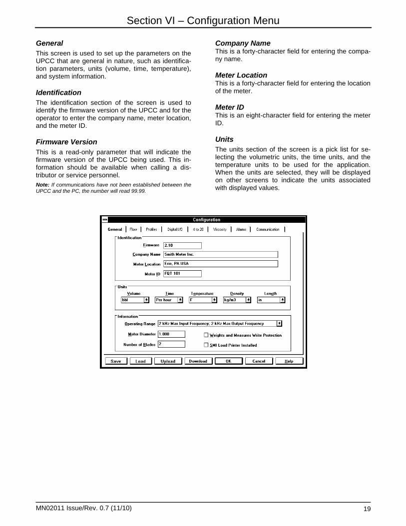
Section VI – Configuration Menu
MN02011 Issue/Rev. 0.7 (11/10) 19
General
This screen is used to set up the parameters on the UPCC that are general in nature, such as identifica-tion parameters, units (volume, time, temperature), and system information.
Identification
The identification section of the screen is used to identify the firmware version of the UPCC and for the operator to enter the company name, meter location, and the meter ID.
Firmware Version
This is a read-only parameter that will indicate the firmware version of the UPCC being used. This in-formation should be available when calling a dis-tributor or service personnel.
Note: If communications have not been established between the UPCC and the PC, the number will read 99.99.
Company Name This is a forty-character field for entering the compa-ny name.
Meter Location This is a forty-character field for entering the location of the meter.
Meter ID This is an eight-character field for entering the meter ID.
Units
The units section of the screen is a pick list for se-lecting the volumetric units, the time units, and the temperature units to be used for the application. When the units are selected, they will be displayed on other screens to indicate the units associated with displayed values.

Section VI – Configuration Menu
MN02011 Issue/Rev. 0.7 (11/10) 20
Volume
The following pick list of units is used to indicate the volumetric units associated with the totals on the run screen as well as the volumetric units associated with the flow rate:
GAL = Gallons BBl = Barrels
FT3 = Cubic Feet
M3 = Cubic Meters
LIT = Litres
Time
The pick list of time events relate to time units asso-ciated with flow rate. The choices are:
Per minute Per hour.
Temperature
The selection of temperature units in the UPCC is as follows:
C = Celsius K = Kelvin F = Fahrenheit
If the temperature units are changed during opera-tion, the UPCC will make the necessary calculations to convert the temperature being used to the new temperature units. For example, if the default tem-
perature is set to 0 C and the units are changed to
degrees F, the UPCC will convert the 0 C to 32 F.
Density
The following pick list of units is used to indicate the density units associated with the calculations made with in the unit. The available units are:
Kg/m3 - Kilogram per cubic meter sg. - specific gravity API - API gravity lbs/gal - pounds per gallon lbs/ft3 - pounds per cubic foot g/cc - grams per cubic centimeter kg/l - kilogram per liter
Length
The following pick list of unit is used to indicate li-near measurement. It will be used to indicate the units being used for meter diameter. The available units are:
in - inches mm. - millimeter
Information
The information section of the screen is used to de-termine the operating input and output frequency range of the unit; to identify the meter diameter and number of blades on the rotor; and to indicate whether the unit is in Weights and Measures protec-tion mode and whether a Smith Meter load printer is installed in the system.
Operating Range
There are two operating ranges that are selectable in the UPCC. The first is 200 Hz maximum input fre-quency and 2000 Hz maximum output frequency. This input/output selection allows the operation of both the digital outputs to be independent of each other. An example of a pulse output configuration is one can be set to compensated times pulse resolu-tion and one can be set to compensated only.
This selection also helps in determining the maxi-mum pulse resolution that can be used. For exam-ple, if the meter can generate a maximum output frequency of 200 Hz, then a maximum pulse resolu-tion of 10 can be entered to provide a maximum output frequency of 2 Khz.
The second selection is 2 KHz (2000 Hz) maximum input frequency and 2 KHz (2000 Hz) maximum out-put frequency. This selection would be used for high resolution meters such as Smith Sentry Series me-ters. This input/output selection allows one pulse output to be programmable. The second output is the quadrature of the first output, and is not pro-grammable. The UPCC will default the second pulse output to the quadrature selection, and no changes will be allowed.

Section VI – Configuration Menu
MN02011 Issue/Rev. 0.7 (11/10) 21
Meter Diameter (Size)
The size of the meter being used in this application should be entered in this parameter. The size should be entered as a whole number (i.e., 3, 6, 8, etc.). The diameter is used in the Reynolds number calcu-lations.
Number of Blades
The number of blades on the rotor of the meter be-ing used is entered in this parameter.
Weights and Measures Write Protection
When this box is selected, the parameters are pro-tected by two levels of security. The first level is the Weights and Measures password.
Note: The password must be set by the user. See “Password Edi-tor” in the Toolbar Functions section of this manual. See the table that lists password descriptions in the “Security” section of this manual for programming entries that are protected by this pass-word.
The second level of security is the key switch con-tact input. Both levels must be present before any changes can be made to the parameters protected under the Weights and Measures password (i.e., the password must be entered and the key switch con-tact must be closed).
Note: Input Contact #1 (Stat In #1) is dedicated to the Weights and Measures keyswitch input if the Weights and Measures write protection check box is checked.
SMI Load Printer Installed
When this box is selected and there is a Smith Meter Load Printer connected to the system and the maxi-mum slew rate of the pulse output is set to 72 Hz.

Section VI – Configuration Menu
MN02011 Issue/Rev. 0.7 (11/10) 22
Flow
This screen is used to set up the frequencies asso-ciated with the flow of product through the meter, the factors associated with the meter, and the modes of the meter.
There are three frequencies that can be programmed that are associated with the flow rate of the product through the meter. The programmable frequencies are:
No Flow Frequency - This is the minimum frequency for which the UPCC will count pulses. The default value for this entry is 0.50 Hz. this value may differ from application to application, depending on how much noise or interference is generated by the sys-tem. If the UPCC appears to be counting pulses when no flow is present, this value should be raised.
Maximum Delta Frequency - The Maximum Delta Frequency is the frequency that is used to calculate the pulse output time period when the meter goes from a no flow condition to the generation of the first two pulses from the pickup coils. This frequency is only used to calculate the first pulse output time pe-riod. The default value for is parameter is 50 Hz.
Maximum Output Slew Rate - The maximum output slew rate is used to ensure that the UPCC does not exceed the speed at which it can change frequen-cies. When used with a Smith Meter Load Printer, this value should be set to 72 Hz. When using the pulse outputs with another manufacturer‟s electrome-chanical counter, check their specifications for the maximum slew rate.

Section VI – Configuration Menu
MN02011 Issue/Rev. 0.7 (11/10) 23
Factors
K-Factor - This factor defines the number of pulses that are received from the meter for one unit of registration. (The counts of registration are selected on the General Configuration screen.) The nominal K-Factor for the Smith Meter Multi-Viscosity Series Turbine meters is as follows:
Meter Size Units Nominal K-Factor
Pul/Unit Volume Meter Size Units Nominal K-Factor
Pul/Unit Volume
3" Gal 14.3 10" Gal 0.4
Bbl 600 Bbl 18.5
Ft3 168.9 Ft
3 5.2
M3 3375 M
3 116
Lit 3.4 Lit 0.1
4" Gal 6 12" Gal 0.3
Bbl 250 Bbl 11.1
Ft3 70.3 Ft
3 3.1
M3 1570 M
3 70
Lit 1.6 Lit 0.1
6" Gal 2.4 16" Gal 0.1
Bbl 100 Bbl 6
Ft3 28.1 Ft
3 1.7
M3 630 M
3 38
Lit 0.6 Lit 0.04
8" Gal 1
Bbl 40
Ft3 11.2
M3 205
Lit 0.3
Table 1

Section VI – Configuration Menu
MN02011 Issue/Rev. 0.7 (11/10) 24
Pulse Resolution
The Pulse Resolution is used for Dual Pulse Chronometry to provide the proper pulse resolution for the meter output to meet API standards of 10,000 pulses per trip when proving.
The Pulse Resolution will increase or decrease the resolution of Pulse Output #1 and Pulse Output #2 when pro-grammed. The pulse resolution can be applied to the raw x resolution output or the compensated x resolution output. (See “Digital I/O” section for programming outputs 1 and 2.)
The maximum pulse resolution that can be applied is determined by two variables based on meter size and one constant. The meter variables are K-Factor and Max Flow Rates, as shown in Tables 3 and 4, respectively. The constant is the maximum frequency limit of the pulse outputs, which is 2000 Hz.
The formula for determining the maximum pulse resolution is as follows:
MaxPulse Resolution(OutputFrequency Limit Hz x Time inSeconds)
(K - Factor Pulses per unit x Max Flow Units per Time)
Example of a 6" MVTM to be configured to measure in BPH:
Max Pulse Resolution =(2000Hz x 3600 Seconds per Hour)
(100Pulses per BBL x 4000BBL per Hour)
Maximum Pulse resolution = 18
Example of a 6" MVTM to be configured to measure in GPM:
MaxPulseResolution=(2000Hz x 60 Seconds per Min)
(2.4Pulses per GAL x 2800 GAL per Min)
Maximum Pulse resolution = 17.85
Round down to 17
Note: If the maximum flow rate of your system will not equal the maximum flow rate shown in Table 3, use the system maximum flow rate in the equation to increase the Maximum Pulse Resolution. This formula does not take into account the viscosity correction factor. The Maximum Pulse Resolution may need to be reduced to account for any viscosity correction factors that are greater than 1 if the meter is running at the maximum flow rate.
Reminder: If the pulse resolution output from the UPCC is being used as a meter pulse input to other equipment that uses a K-Factor input (i.e., SyberTrol, AccuLoad II, GeoFlo, etc.), the nominal K-Factor entered in the UPCC must be multiplied by the value entered for the pulse resolution in the UPCC to generate the corrected K-Factor to be entered in the external equipment.
Maximum K-Factor %
The maximum K-Factor is used to set a limit on the deviation of the K-factor, it is required to meet the Canadian Weights and Measures regulations.

Section VI – Configuration Menu
MN02011 Issue/Rev. 0.7 (11/10) 25
Multi-Viscosity Series Turbine Meters
Turbine Size Maximum Flow
Rate (BPH)
Nominal K-Factor
Pulses/BBL
Maximum
Frequency
Pulse resolution
to Match Sentry
Series Output
3" 900 600 150.00 4
4" 1900 250 131.94 8
6" 4000 100 111.11 11
8" 7500 40 83.33 13
10" 12,500 18.5 64.24 28
12" 19,000 11.1 58.58 24
16" 27,000 6 45.00 18
Table 2
Modes
There are three modes that can be programmed in the UPCC: the type of compensation used; the mode of flow through the meter; and the pickup coil connec-tion. The first window under “Modes” is a read only window that indicates the meter profile that is active. The profiles are defined on the profile screen.
Active Profile - This parameter programs the profile that is active and from which the present values are being generated.
Compensation Type - This parameter programs the type of compensation that is to be used. There are four choices:
Not Used - There is no viscosity compensation being used.
Viscometer - The viscosity compensation is based
on the frequency input from a SolarTron viscome-ter.
Temperature - The viscosity compensation is based on the temperature input and the temperature versus viscosity curve that was programmed on the Profile screen.
4-20 - The viscosity compensation is based on a pro-portional 4-20 mA input from a viscometer.
Bidirection Mode
(not used on MVTM) This entry determines how the UPCC is to determine the direction of flow through the meter. There are three choices for this entry:
Off - Not used; the UPCC assumes that all flow through the meter is in the forward direction (stan-dard for the Smith Meter MVTM).
Quadrature - The UPCC uses the two pulse inputs from the meter to determine the flow direction through the meter. If pulse stream A is leading pulse stream B, then flow is in the forward direction. If pulse stream B leads pulse stream A, then flow is in the re-verse direction.
Input Contact - One of the three input contacts can be programmed to indicate a reverse flow condition when the contact is energized. If the contact is disen-gaged, the flow is in the forward direction.
Pickup Coil Connection
This parameter is used to indicate to the UPCC how many pickup coils are being used for this application. The choices are one coil or two coils. If dual pulse security or sensing the flow direction using quadra-ture is required, then two pickup coils are required on the meter and programmed in this parameter.

Section V – Configuration Menu
MN02011 Issue/Rev. 0.7 (11/10) 26
Dual Pulse Security
To activate the Dual Pulse Security, either press “ALT D” on the keyboard or use the mouse and click on “Dual Pulse Security.” When activated, an “X” will appear in the box at the end of the phrase “Dual Pulse Security.” The UPCC utilizes Level A security. The Level A security will provide an alarm when one of the pulse streams is missing and will also continue totalizing using the remaining pulse stream. In order to utilize the dual pulse security, the meter must be supplied with two pickup coils and the pickup coil connection must be programmed for two coils.
Pulse Output Configuration
This area on the screen is used to program the two pulse outputs that are available on the UPCC.
Pulse Output Configuration
There are two pulse outputs that can be configured in the UPCC. Each of the outputs is independently pro-grammed using the pick list method that was de-scribed in the programming section of this manual. The options for the pulse outputs are:
Pulse Output #1 - The primary pulse output of the unit. The information from this output is displayed on the “Present Value” screen.
Disabled - The pulse outputs are not used.
Raw echo of input pulses - The input pulses from the pickup coils of the meter are echoed out.
Raw Pulse x Pulse resolution - The input pulses from the pickup coils of the meter times the pulse resolution that is programmed in the UPCC are out-put on J3 pin 3 for channel 1 and pin 4 for channel 2.
Compensated Pulses - The input pulses from the pickup coils of the meter times the viscosity correc-tion factor that is calculated by the UPCC.
Compensated Pulses x Pulse Resolution - The in-put pulses from the pickup coils of the meter times the viscosity correction factor that is calculated by the UPCC times the pulse resolution that is programmed in the unit.
Pulse Output #2 - In addition to the above options, Pulse Output #2 has a quadrature of Output #1 selec-tion.
Quadrature of Output #1 - The pulse output of out-put #2 is 90 electrical degrees out of phase in rela-tionship to Pulse Output #1. The quadrature output is designed to meet the parameters of Pulse Security Level A to the following specifications: IP 252/76 Part XIII, Section 1; ISO 6551-1982; API Chapter 5, Sec-tion 5, June 1982.

Section V – Configuration Menu
MN02011 Issue/Rev. 0.7 (11/10) 27
Profiles This screen is used to configure the meter‟s profile for viscosity compensation constants; to select direct entry of constants in the constant entry options; to indicate temperature calibration points; to calculate constants from points selected in the constant entry options; and to enter the viscosity coefficients that are supplied with the multi-viscosity turbine meter.
Meter Profile The meter profile will allow the operator to program and to choose the profile that is to be used for the current batch. Up to three profiles can be set up for each meter. The profiles are selected via a pick list in the meter profile number window. In most applica-tions one profile will be sufficient but if you have a case where there are two sets of internals for a me-ter a separate profile could be set up for each inter-nal kit.
Label Each of the three meter profiles has a label or name associated with it. This name is entered in the Label window. To select the Label window, either use the mouse or TAB key, or press “ALT L” to get the cur-sor in the Label window. Once in the window, a label of up to ten characters can be typed in from the key-board. If more than ten characters are entered, the error message will pop up. Pressing “ENTER” or clicking with the mouse on the “OK” box will return the cursor to the Label window where the error can be corrected.
Constant Entry Options
The Constant Entry Options window is used to indi-cate how the UPCC is to determine the viscosity compensation constants. There are two methods that can be employed by the unit and they are listed on a pick list. The options are:
Viscosity Compensation Constants
Direct entry of constants - When selected, the Vis-cosity Compensation Constants windows will be-come available and the constants A and B will be entered directly. Those constants will then be used by the UPCC to determine the viscosity correction factor. The constants are calculated from ASTMD341-93, Section XI.

Section VI – Configuration Menu
MN02011 Issue/Rev. 0.7 (11/10) 28
Viscosity vs. Temperature Data Points
Calculate constants from points - This selection will activate the Temperature Calibration Points win-dow where two points for temperature and the asso-ciated kinematic viscosity (CST) can be entered. From this linear curve, the UPCC will calculate the viscosity compensation constants that will be used to determine the viscosity correction factor.
Enter Re Look-Up Points - This menu is used
when the user does not want to replace the factory coefficients, but wants to create an extension beyond the range of the factory coefficients. The UPCC will calculate a straight-line interpolation to the user defined end points. Piece wise linear inter-polation will be utilized for calculation values.
When the Enter Re Look-Up Points button is pressed from the Profile Menu a sub menu with the heading “Re Look-Up Points” will be displayed. This menu is used to calculate the Reynolds Numbers that are beyond the normal range of the Meter Coef-ficients (above and below). Only one data point entry is available above the factory supplied high value because meter performance is extremely predictable in this area.
The user will supply the data gathered from the prov-ing of the meter. The data required for entry is Flow Rate, K-Factor at the flow rate, and Fluid Viscosity at the tested flow rate.
The Fluid Viscosity is either measured from a Vis-cometer Head, or is measured using a Brookfield Viscometer or an equivalent Rheological measure-ment instrument. Accuracy of data is of the up most importance as this data is used to calculate the me-ter factor correction for interpolating the curve to the higher and lower points.
Enter Calibration Points - This menu is used
when the user requires a new set of coefficients to replace the factory coefficients.
When the Enter Calibration Points button is pressed from the Profile Menu a sub menu with the heading “Curve Fit Points” will be displayed. This menu is used to calculate the Meter Coefficients. The cus-tomer will supply the data gathered from the proving of the meter. The data required for entry is Flow Rate, K-Factor at the flow rate, and Fluid Viscosity at the tested flow rate, the program requires a mini-mum of ten data points with a maximum of 15 data points. The Fluid Viscosity is either measured from a Viscometer Head, or is measured using a Brookfield Viscometer or an equivalent Rheological measure-ment instrument. Accuracy of data is of the up most importance as this data is used to calculate the me-ter coefficients. After the ten to fifteen data points are entered the Calculate button is pressed. The UPCC will automatically calculate the meter coeffi-cients, and display the Coefficients and the Standard Error (based on a linear regression analysis) on the current menu.
Upon the selection of the OK button the coefficients will be entered into the Viscosity Profile Table that is displayed from the Profile Menu. If the user decides to not use the calculated data, the Cancel button is pressed and the calculated coefficients are not placed into the Viscosity Profile Table. There are three tables available, the data will be placed into the active profile table, that is to say the profile that is selected from the pull-down pick list.
Note: All calculations are base on BBL as the base unit, the soft-ware will convert units of flow. K-Factor is not automatically con-verted, i.e. if flow is entered as BBL and then the flow is changed to M3, the flow rates will be converted however the K-Factors will have to be manually converted.

Section VI – Configuration Menu
MN02011 Issue/Rev. 0.7 (11/10) 29
Procedure for Field Calculation of
Calibration Points
1. Prove meter with a minimum of ten points (Points could be a combination of flow rate and viscosi-ty‟s) using accepted API methods.
Example: Meter would be proven at expected low flow rate, mid flow rate, intermediate high flow rate and high flow rate and at the expected low viscosity, mid vis-cosity and high viscosity. The results from this test-ing would produce twelve data points, satisfying the minimum ten data point requirement.
2. Proving data required from ten point test: Flow Rate, Fluid Viscosity during the prove, and Meter K-Factor at test point. The data gathered will be used in the Profile Menu Selection: “Enter Cali-bration Points”.
Meter Coefficients - The meter coefficients can be either entered from the data received with the meter when delivered from the factory or by determining the calibration data from proving the meter. The data
card supplied with the meter should have the coeffi-cients listed, they would then have to be copied into the UPCC. The other method is go through the pro-cedure above to determine the calibration points and then the UPCC will calculate the meter coefficients.
Reynolds Number
This area of the screen is used to set Reynolds numbers that will be used to switch the way the UPCC operates with regard to the Reynolds number.
Reynolds Number “Re-Low” - This entry is used to control the switch point between the UPCC equation and the low value look-up points.
Reynolds Number “Re-High” - This entry is used to control the switch point between the UPCC equa-tion and the high value look-up point.
Reynolds Number “Re-Fault” - This entry is used to set an alarm limit for Re values that exceed this setting.

Section VI – Configuration Menu
MN02011 Issue/Rev. 0.7 (11/10) 30
Digital I/O Configuration
This screen is used to configure the two digital out-put contacts and the three input contacts.
Output Contact Configuration
The two output contacts can be set up for alarm out-puts, meter direction indication, Weights and Meas-ures mode indication, or Weights and Measures program mode indication. When programmed for alarm indicators, the switch outputs can be set to latch on the alarm. In this case, the output will re-main latched until the “Clear Latched Alarms” button is selected on the “Control Options” screen. If the output is programmed for instantaneous, it will be activated when the alarm occurs and will be deacti-vated automatically when the alarm state comes back into compliance. The UPCC can be set up by the operator for any, all, or none of the alarms to cause the output contacts to be energized. Also, the alarms will be shown on the alarm list and/or on the alarm popup list. If an alarm occurs, an alarm condi-tion will be indicated at the bottom of the Run Mode screen.
The alarm conditions are as follows:
Missing Pulse Alarm - Indicates that when the UPCC is set up for dual pulse security, the “A” pulse is not being received. The Dual Pulse Security check box must be checked in the Flow Menu.
Minimum Input Frequency Alarm Limit - Indicates that when flow is present in the system, the input frequency is below the minimum frequency that was programmed on the Alarm Limit screen.
Minimum Temperature Alarm Limit - Indicates that the product temperature is below the minimum that was programmed on the Alarm Limit screen.
Minimum Viscosity Alarm Limit - Indicates that the product kinematic viscosity being measured is below the minimum kinematic viscosity that was pro-grammed on the Alarm Limit screen.
Minimum Flow Alarm Limit - Indicates that the flow rate being measured by the meter is below the min-imum that was programmed on the Alarm Limit screen.
Minimum Compensated Flow Alarm Limit - Indi-cates that the compensated flow rate is below the minimum that was programmed on the Alarm Limit screen.
Minimum 4-20 mA Input Alarm Limit - Indicates that the 4-20 mA input is below the minimum that was programmed on the Alarm Limit screen.
RAM Failed Self-Test - Indicates a RAM failure.
Maximum Input Frequency Exceeded - Indicates that input frequency has exceeded the maximum value programmed on the Alarm Limit screen.
Invalid Power Fail CRC - Indicates that the Cyclic Redundancy Check (CRC) detected an error when power was restored to the unit.
EPROM CRC Failure - Indicates that the EPROM Cyclic Redundancy Check (CRC) detected an error in the EPROM CRC.
Section VI – Configuration Menu
MN02011 Issue/Rev. 0.7 (11/10) 31
Invalid Configuration CRC - Indicates that the con-figuration Cyclic Redundancy Check (CRC) detected an error in the configuration CRC.
NV RAM CRC Failure - Indicates that the Non-Volatile RAM Cyclic Redundancy Check (CRC) de-tected an error in the CRC stored in non-volatile RAM.
Missing Pulse B Alarm - Indicates that when the UPCC is set up for dual pulse security, the “B” pulse is not being received.
Maximum Input Frequency Alarm Limit - Indicates that the input frequency is above the maximum fre-quency that was programmed in the Alarm Limit screen.
Maximum Temperature Alarm Limit - Indicates that the product temperature is above the maximum that was programmed on the Alarm Limit screen.
Maximum Viscosity Alarm Limit - Indicates that the product viscosity has exceeded the maximum ki-nematic viscosity programmed on the Alarm Limit screen.
Maximum Flow Alarm Limit - Indicates that the raw flow rate has exceeded the maximum raw flow rate programmed on the Alarm Limit screen.
Maximum Compensated Flow Alarm Limit - Indi-cates that the compensated flow rate has exceeded the maximum compensated flow rate programmed on the Alarm Limit screen.
Maximum 4 to 20 mA Input Alarm Limit - Indicates that the current input has exceeded the maximum value programmed on the Alarm Limit screen.
No-Flow Condition - Indicates that there is no flow or no indication of flow through the meter.
Failed Temperature Input - Indicates a short or open condition in the RTD temperature circuit.
Failed Viscometer Input - Indicates that the visco-meter head has failed.
The two output contacts can also be used to indi-cated the following:
Meter Direction - Indicates that the direction of flow through the meter. The output would be activated for reverse flow and deactivated for forward flow.
Weights and Measures Mode - Indicates when the UPCC is being operated in the Weights and Meas-ures Mode. The check box in the General Configura-tion Menu for Weights and Measures write protection is disabled.
Weights and Measures Program Mode - Indicates when the UPCC is in the Weights and Measures Program Mode. The key switch contact input is closed to allow access to Weights and Measures program parameters.
Input Contact Mode Configuration
There are three input contacts that can be confi-gured in the UPCC. Each of the contacts is inde-pendently programmed using the picklist method, except for the following restrictions.
Restrictions - Input Contact #1 (Stat In #1) is dedi-cated to the Weights and Measures Keyswitch Input if the Weights and Measures write protection check box is checked in the General Configuration menu. When checked, the label for Input Contact #1 will display “Weights and Measures Key” and the selec-tor arrow will be hidden.
Weights and Measures - The input contact is used as a Weights and Measures input normally in con-junction with a key switch. Weights and Measures parameters cannot be changed unless the contact is activated.
Input Contact #2 (Stat In #2) is dedicated to the So-
larTron Viscometer Input if “Viscometer” is se-lected from the Compensation Type pick list in the Flow Configuration menu. When selected, the label for Input Contact #2 will display “Viscometer” and the selector arrow will be hidden. The viscometer input
is used as a frequency input from the SolarTron Transducer.
Input Contact #3 (Stat In #3) has no restrictions and can be programmed for any items in the pick list.
The options for programming the input contacts are:
Not Used - The inputs are not used.
Batch End - The input contact is used to indicate the end of a batch. When this signal is received, the UPCC ends the current batch storing the data in memory and starts a new batch.
Flow Direction - The input contact is used to exter-nally select which totalizer (forward or reverse) to in-crement and which meter coefficients (forward or re-verse) to use from the Profile Configuration menu. Note: The MVTM is a uni-directional meter. This selection should not be used for this application.
Alarm Acknowledgment/Reset - The input contact is used to acknowledge and reset existing alarms.

Section VI – Configuration Menu
MN02011 Issue/Rev. 0.7 (11/10) 32
4-20 mA Configuration
This screen is used to configure the two 4-20 mA outputs and the 4-20 mA input, if they are being used in the application.
Note: The 4-20 mA input and outputs must be calibrated before using. Refer to Menu Bar Functions tools.
4-20 mA Outputs
There are two 4-20 mA outputs that can be confi-gured for the application. The selections/options for each are identical and include the mode or function, the low engineering value (4 mA), the high engineer-ing value (20 mA), the gain, and the offset.
Mode
To program the unit for the mode or function of the 4-20 mA output, select the mode under the output re-quired. When highlighted, either use the up or down arrow or click with the mouse on the arrow at the right side of the box. Using the up or down arrow will show one selection at a time. Using the mouse will display the entire pick list of options for this output. The op-tions available for the 4-20 mA outputs are as follows:
Disabled - Output is disabled and not used for this application.
Raw Flow Rate - The raw flow rate (meter pulses/K-factor) is output in either units per minute or units per hour as selected on the General screen.
Comp x Flow Rate - The Compensated Flow Rate is the raw flow rate times the viscosity correction factor.
Temperature - The temperature that is being input into the UPCC is output in the units that are pro-grammed on the General screen.
Kinematic Viscosity - The kinematic viscosity that is being displayed on the Run screen is output in the units that are set up using the “U” scaling factor. If the factor is 1.000, the units will be in centistokes (Cst).
Low (Minimum) Engineering Value
This entry allows the operator to program the Raw Flow Rate, Compensated Flow Rate, Temperature, or Kinematic Viscosity to the appropriate engineering value which is to be represented by the minimum (4 mA) value. A valid entry must be less than the pro-grammed value for the maximum engineering value.
High (Maximum) Engineering Value
This parameter allows the operator to program the Raw Flow Rate, Compensated Flow Rate, Tempera-ture, or Kinematic Viscosity to the appropriate engi-neering value and which is to be represented by the maximum (20 mA) value. A valid entry must be greater than the programmed value for the minimum engineering value.
Gain
This entry is used to enter the calibration correction for the 4-20 mA output. In normal operation, there is no need to enter a value in this parameter. It should be used as a read only value unless there is a need to artificially adjust the 4 or 20 mA value to other than
Section VI - Configuration Menu
MN02011 Issue/Rev. 0.7 (11/10) 33
4-20 mA. The UPCC will automatically calculate the gain when calibration data is entered in the calibra-tion program area. The calibration program area is located under “Tools” on the Run Mode screen. For further information, see the description under Tools/Calibration.
Offset
This parameter is used to enter the offset required to calibrate the 4-20 mA output. In normal operations, there is no need to enter a value in this parameter. It should be used as a read only value unless there is a need to artificially adjust the 4-20 mA values to other than 4-20 mA. The UPCC will automatically calculate the offset when calibration data is entered in the cali-bration program area. The calibration program area is located under “Tools” on the Run Mode screen. For further information, see the description under Tools/Calibration.
4-20 mA Input
There is one 4-20 mA input that can be programmed for either to be disabled, a generic input , a viscosity input or a temperature input.
Disabled - This input is not used.
Generic Input - This input will read a 4 - 20 mA input signal and is not assigned to any specific measure-ment. (for future development).
4-20 mA Temperature Input - This input can be used with any 4-20 mA temperature transmitter or it can be used if more than one UPCC is to be con-
nected to one common SolarTron viscometer head.
The RTD input from the SolarTron viscometer head would be connected to the first UPCC. The first UPCC would have one of its 4-20 mA outputs pro-grammed for a temperature echo. This 4-20 mA out-put would then feed the remaining UPCC‟s 4-20 mA input. All units on the common manifold would read the same temperature.
4-20 mA Viscometer Input - This input is used if a
viscometer other than the SolarTron Model 7827 (or equivalent) is used.
Viscosity
The Viscosity Configuration screen is used to set up the viscosity parameters when interfacing with a So-
larTron Model 7827 viscometer head. To set up the density constants and the viscometer range con-
stants, a copy of the SolarTron calibration certifi-cate is required. Reference Appendix B for an exam-ple.
Density
The entries in this box are used for entering the den-
sity constants that are found on the SolarTron Cali-bration Certificate and are used in the calculation of the density that is displayed on the Run Mode screen of the UPCC. The three density constants located on the left-hand side of the box (K0, K1, and K2) and found approximately in the center and to the right of the calibration certificate. The density constants are used to calculate the relative density of the product.
If temperature corrected density (reference Density) is required by the application, then the box beside “Use Temperature Corrected Density” and enter the constants K18 and K19. If the constants K18 and K19 are entered and the box beside “Use Temperature Corrected Density” is not checked, the density dis-played and used for the calculation will be noncor-rected density (relative density). The constants K18 and K19 are found below the constants (K0, K1, and K2) on the calibration certificate.

Section VI – Configuration Menu
MN02011 Issue/Rev. 0.7 (11/10) 34
Scaling Factors
The parameters in this box are used for entering factors that would change the units and the values that are being displayed. A value must be entered in these parameters or the Dynamic Viscosity (V), the Density (Kd) and the Kinematic Viscosity (U) on the Present Value screen will be zero. If a “1” is entered in each of these parameters, the defaults are as follows:
Density = Kg/m3 (kilogram per meter cubed)
Dynamic Viscosity = cP (centipoise) Kinematic Viscosity = Cst (centistokes)
See , Table 4, and Table 5 for conversion factors and the values that should be entered for the scaling factors if the units are to be different than the defaults that are shown above.
Density Units (Kd)
lb/ft3 g/cc Kg/M
3
lb/ft3 1 0.01602 16.0185
kg/M3 0.062428 0.001 1
Table 3
Example - Density
The default value for density is kg/m3 (kilograms/cubic meter) and the scaling factor = 1.00.
To convert the units from kg/m3 to g/cc (grams/cubic centimeter), the scaling factor should be entered as 0.001.
To convert the units from kg/m3 to lb/ft3 (pounds/cubic foot) the scaling factor should be entered as 0.062428.

Section VI - Configuration Menu
MN02011 Issue/Rev. 0.7 (11/10) 35
Dynamic Viscosity Units (v)
cP mPa.s Pa.s
cP 1 1 1000
Table 4
Example - Dynamic Viscosity
The default value for the dynamic viscosity is cP (centipoise) and the scaling factor = 1.00.
To convert the dynamic viscosity from cP to mPa‟s (millipascals), the scaling factor is the same as cP = 1.00.
To convert the dynamic viscosity from cP to Pa‟s (pascals), the scaling factor is 1000.00.
Kinematic Viscosity (U)
CST in2/S ft
2/S cm
2/S
CST 1 0.00155 0.010765 0.01
Table 5
Example - Kinematic Viscosity
The default value for the kinematic viscosity is Cst (centistokes) and the scaling factor = 1.00.
To convert the kinematic viscosity from Cst to in2/s (inches squares/second), the scaling factor is 0.00155.
To convert the kinematic viscosity from Cst to ft2/s (feet squared/second), the scaling factor = 0.010765.
To convert the kinematic viscosity from Cst to cm2/s (centimeters squared/second), the scaling factor = 0.01.

Section VI – Configuration Menu
MN02011 Issue/Rev. 0.7 (11/10) 36
Viscometer Range Constants
The parameters located within this box are used to enter the viscosity range of the product and the gen-eral viscosity constants V0, V1, and V2 for each vis-cosity range. The viscosity ranges are as follows:
Ultra-Low Range = 0.5 cP to 10 cP Low Range = 10 cP to 100 cP Medium Range = 100 cP to 1000 cP High Range = 1000 cP to 12,500 cP
The constants associated with each one of these
ranges are located on the SolarTron Calibration Certificate and must be entered as they are listed on the certificate. More than one range may appear on the certificate. If so, enter the data for all the ranges and then ensure that the correct range (ultra low, low, medium, or high) is selected for the product currently being run in the pipeline.
Temperature The entries in the Temperature box are used for set-ting the unit to operate with different types of sensors and also provide the ability to enter the calibration offset for the temperature sensor selected.
The calibration offsets for the temperature sensor al-lows for the correction of any errors that are found in the temperature measuring device. Most of these temperature measurement devices will be supplied with a certificate indicating the calibration error. If a calibration certificate is not available, the temperature measurement device can be checked against a certi-fied thermometer and a calibration offset can be cal-culated.
The temperature sensor types that can be selected for use with the UPCC are:
None - No temperature sensors associated with the operation.
RTD - 100 temperature element with a 0.00385
/ / C temperature coefficient installed separately
or, as part of the SolarTron Viscometer head.
DS1820 - Future use (Dallas DS1820 thermometer)
4-20 mA Temperature Transmitter Input - An ana-log temperature transmitter is used.
Defaults
The entries in this box will allow the entry of a default or maintenance temperature and/or kinematic vis-cosity value to be used when a temperature element or viscosity input is not installed or working but tem-perature and/or viscosity-related calculations are de-sired. The default temperature will be used for the temperature if the temperature element falls. The de-fault viscosity will be used for the viscosity if the vis-cosity input falls. The temperature units will be de-pendent on the units selected on the General screen. The viscosity units will be dependent on the “U” scal-ing factor used above. Also a default density can be programmed in this area. The default density will be used for calculations in UPCC requiring density.

Section VI – Configuration Menu
MN02011 Issue/Rev. 0.7 (11/10) 37
Alarms
The Alarms configuration screen is used to set up the range (minimum and maximum values) allowed for the input frequency, temperature, kinematic viscosity, flow, compensated flow, and the 4-20 mA input be-fore an alarm is generated. Note that when both the minimum and maximum values are set to zero, the alarm is disabled.
Input Frequency Alarm These parameters are used to set up the minimum and maximum allowable values in Hertz (Hz) for the input frequency of the meter without generating an alarm.
Temperature
These entries are used to set the minimum and max-imum allowable values in degrees F, C, or K for the temperature of the product without generating an alarm. The temperature units are programmable on the General Configuration screen.
Kinematic Viscosity
These parameters are used to set up the minimum and maximum allowable kinematic viscosity values being measured by the viscosity input before an alarm will occur in the UPCC. The viscosity units are in centistokes.
Raw Flow
These entries are used to set the minimum and max-imum allowable values for the raw flow rate of the unit. The raw flow rate of the meter is calculated by the number of incoming pulses divided by the pro-grammed K-Factor. The values programmed in this parameter should not be below the minimum or above the maximum flow range of the meter. Flow ranges for the Smith Meter Multi-Viscosity Turbine Meters are provided in Table 6 below. The label for units and the time period displayed with this entry are configured on the General Configuration screen. If the value for the raw flow rate is outside of the pro-grammed range for more than four seconds, an alarm will be generated.

Section VI – Configuration Menu
MN02011 Issue/Rev. 0.7 (11/10) 38
Meter Flow Ranges
Linear Flow Range
Meter Size Units Minimum Maximum
3" BPH 90 900
M3/h 14 140
GPM 63 630
LPM 238 2380
4" BPH 190 1900
M3/h 30 300
GPM 133 1330
LPM 503 5030
6" BPH 400 4000
M3/h 64 640
GPM 280 2800
LPM 1060 10600
8" BPH 750 7500
M3/h 119 1190
GPM 525 5250
LPM 1987 19870
10" BPH 1250 12,500
M3/h 199 1990
GPM 875 8750
LPM 3312 33120
12" BPH 1900 19,000
M3/h 302 3020
GPM 1330 13300
LPM 5034 50340
16" BPH 2700 27,000
M3/h 429 4290
GPM 1890 18900
LPM 7154 71540
Table 6

Section VI – Configuration Menu
MN02011 Issue/Rev. 0.7 (11/10) 39
Compensated Flow
These entries are used to program the minimum and maximum allowable compensated flow rates without causing an alarm to be generated. The compen-sated flow is the raw flow rate times the viscosity factor that is being used by the UPCC. The label for units and time period displayed with these entries are configured on the General Configuration screen. If the value for the compensated flow rate is outside of the programmed range for more than four seconds, an alarm will be generated.
4-20 mA Input
These entries are used to program the minimum and maximum allowable inputs for this 4-20 mA signal without causing an alarm to be generated.

Section VI – Configuration Menu
MN02011 Issue/Rev. 0.7 (11/10) 40
Communications
The Communications Configuration screen is used to set up the communication parameters of the UPCC. It should be noted that the settings for the UPCC and the PC or laptop must match in order to establish communications between the two devices. The UPCCMate will automatically set the PC set-tings to match the UPCC communications settings. For further information, on the PC communications screen, refer to Tool Bar Functions (Edit) PC Com-munications.
UPCC Setup
Unit ID - The unit ID can range from a number of 1 to 255. The ID defines the address of a particular unit. No duplication of unit Ids (addresses) is allowed on a common serial line, as this will cause data colli-sion.
Modbus Type - Select the Modbus type of commu-nications for the UPCC communications. The two selections that are available are RTU and ASCII. The selection defines the bit contents of the mes-sage fields and how the information will be packed into the message fields and decoded.
RTU - Remote Terminal Unit, each 8-bit byte in a message contains two 4-bit hexadecimal characters. Each message must be transmitted as a continuous stream.
ASCII - American Standard Code for Information In-terchange, each 8-bit byte in a message is sent as two ASCII characters. ASCII allows time intervals of up to one second to occur between characters, without causing an error.
Note: This entry must match the PC setup.
Baud Rate - There are five baud rates available for the transmission of data to and from the PC or lap-top: 1200, 2400, 4800, 9600, and 19200.
Note: This entry must match the PC setup.
Parity - This entry configures the UPCC for Even or Odd Parity Checking or for no parity checking. This will determine how the parity bit will be set in each character. The selections are: None - Used for RTU Modbus with eight data bits Odd - Used for ASCII Modbus with seven data bits Even - Used for ASCII Modbus with seven data bits
Note: This entry must match the UPCC setup.
RTS Delay - This entry allows the user to set the modem delay time between the transmission of data. The UPCC will set the line high before transmission of data using the entered delay time.

Section VII – Present Value Mode
MN02011 Issue/Rev. 0.7 (11/10) 41
Present Value
The Run Screen is used to display the current status of the meter‟s operation. Information supplied on this screen is the present batch information, meter infor-mation, non-resettable pulse totals, flow rates, com-pensation information, flow status, 4-20 mA output and input status, and the digital input and output sta-tus.
Present Batch Information The present batch information provides the following information for the current batch that is being run. The information includes the ticket number; the time the batch started; the current time; the meter profile; and the forward and reverse totals for raw pulses; compensated pulses times the pulse resolution; and the volume that has been delivered.
Ticket Number
This is the ticket number that is associated with the current batch that is being delivered. The ticket number will increment by one each time the batch is ended and a new batch is started.
Start Time The two windows associated with the start time indi-cate the date and time that the current or present batch was started. The time is military time.
Current Time
The two windows associated with the current time indicate the current date and time. The time repre-sentation is in military time.
Meter Profile The meter profile window indicates which meter pro-file is being used for the current batch. The profile is selected from the Control Options screen.
Raw Pulses
The two raw pulses windows indicate the number of raw pulses that have been received from the meter in the forward and reverse directions. In order for the UPCC to indicate reverse pulses, one of two situa-tions must be present: one or two pickup coils must be present on the turbine meter, and “Bidirection Mode” on the flow screen must be selected for quad-

Section VII – Present Value Mode
MN02011 Issue/Rev. 0.7 (11/10) 42
rature. The second method of determining reverse flow is through an input contact selected on the “Dig-ital I/O” screen. One of the input mode contact con-figurations would have to be programmed for flow di-rection.
Comp x Pulse Resolution
The two “Comp x Pulse Resolution” windows that are shown on the above screen are programmable and depend on the selection of the “Digital I/O Con-figuration” screen for pulse output #1. There are five selections or choices for this output and the readings in the two windows on the run screen.
Disabled - The values in the forward and reverse windows will not be used.
Raw echo of input pulses - The values in the for-ward and reverse windows will be the same as the raw pulses in the top windows.
Raw Pulse x Pulse Resolution - The values in the forward and reverse windows will be the raw pulses times the pulse resolution that is set up on the flow configuration screen.
Compensated pulses - The values in the forward and reverse windows will be the raw pulse times the compensation factor being generated and used by the UPCC to correct for the changes in temperature and viscosity.
Compensated x Pulse Resolution - The values in the forward and reverse windows will be the raw pulses times the compensation factor being gener-ated times the pulse resolution that is programmed on the flow configuration screen.
Volume
The two volume windows displayed on the screen are based on the raw pulses divided by the K-factor. The K-factor is set up on the “Flow Configuration” screen and is based on the number of pulses per unit volume being received from the meter.
Present Batch Averages
The windows displayed in the Present Batch Aver-ages box are based on the averages for the present batch. The values are the average conditions of the product that has flowed through the meter since the last batch had been ended. The averages being measured and displayed include temperature, kine-matic viscosity and Density.
Temperature - The “Temperature” window displays the average temperature of the product that is being measured by the temperature element. The temper-ature units that are being displayed are programmed by the operator on the “General Configuration” screen.
Kinematic Viscosity - The “Kinematic Viscosity” window displays the average kinematic viscosity that is being derived from the readings from the Solartron viscometer head. If the Solartron viscometer head is not being used and viscosity is being determined by an alternate method, there will be no value in the “Kinematic Viscosity” window. The unit for Kinematic viscosity when using the viscometer head is centis-tokes (cst).
Density - The “Density” window displays the aver-age density that is being read from the Solartron vis-cometer head. If the Solartron viscometer head is not being used and viscosity is being determined by an alternate method, there will be no value in the “Density” window. The units for density when using the viscometer head are kg/m3.
Meter
The information displayed on the “Run” screen in the windows designated for the meter is the following: input frequency, flow direction, K-factor, pulse, pulse resolution, and meter ID.
Frequency - The frequency displayed is the number of pulses per second that is being received by the UPCC from the meter.
Section VII – Present Value Mode
MN02011 Issue/Rev. 0.7 (11/10) 43
Flow Direction - The “Flow Direction” window indi-cates the direction of the flow through the meter. This is automatically determined if the meter is equipped with two pickup coils and dual pulse qua-drature is being used. If quadrature is not being used, then the flow direction would have to be de-termined by a switch input and the UPCC would have to be programmed for one of the inputs to be “flow direction.”
K-Factor - The K-factor indicated on the “Run” screen window is determined from the K-factor that is set up by the operator on the “Flow Configuration” screen and is an indication of the number of pulses received from the meter per unit volume of liquid flowing through the meter.
Pulse Resolution - The pulse resolution entry indi-cates the number that is being applied to the meter pulses to either increase or decrease the pulse reso-lution of the meter output. A positive number greater than 1.00000 in this entry will increase the meter pulse output resolution, a positive decimal number of .99999 through .00001 will decrease the meter pulse output resolution.
Note: Do not exceed the maximum pulse resolution numbers giv-en in Table 3 for matching the pulse output of a Sentry Series Turbine Meter.
These pulses are used for the “Forward” and “Re-verse” present batch information, as well as the non-resettable totals if pulse resolution pulses are se-lected in the pulse output configuration for output number one.
Meter ID - The meter ID that is indicated is the value that was entered by the operator on the “General Configuration” screen of the program. The ID identi-fies the meter that the run data is being displayed for. It is important for meter identification if the UPCC is communicating with more than one meter.
Non-Resettable Pulse Totals
The “Non-Resettable Pulse Totals” windows display the accumulated pulses for both the forward and re-verse flow directions. The raw non-resettable pulse totals are always displayed. These are the raw pulse totals as they are received from the meter. The second set of windows in the non-resettable pulse totals box will depend on how “Pulse Output #1” is configured. These windows will display one of the following:
Disabled - No totals will be displayed
Raw echo of input pulses - Non-resettable totals would match the raw non-resettable pulse totals.
Raw Pulse * Pulse resolution - The non-resettable totals would be the raw non-resettable totals times the pulse resolution that is displayed in the meter box.
Compensated Pulses - The non-resettable totals would be the raw non-resettable totals times the compensation factor(s) being used by the UPCC.
Compensated * Pulse Resolution - The non-resettable totals would be the raw non-resettable to-tals times the compensation factor(s) times the pulse resolution.
Note: If the selection for the second set of non-resettable totals and the pulse output #1 is changed, the non-resettable totals dis-played will be changed to the new selection. All non-resettable to-tals are tracked internally in the UPCC.
Flow Rates
The windows in this box provide the data for the in-staneous flow rate and the batch average flow rate.
Instantaneous
This window is used to display the current flow rate of the meter. The UPCC calculates the instantane-ous flow rate using incoming pulses, the K-factor, and a unit of time.
Batch Average
This window is used to display the average flow rate at which the product has been flowing in the current or present batch.
Compensation
The windows displayed in the compensation box are based on the compensation being used and calcu-lated in the UPCC. The values are the current condi-tions of the product flowing through the meter. These conditions include temperature, density, dy-namic viscosity, kinematic viscosity, and the viscosi-ty correction factor.
Temperature - The “Temperature” window displays the current temperature of the product that is being measured by the temperature element. The temper-ature units that are being displayed are programmed by the operator on the “General Configuration” screen.
Density - The “Density” window displays the current density that is being read from the Solartron visco-

Section VII – Present Value Mode
MN02011 Issue/Rev. 0.7 (11/10) 44
meter head. If the Solartron viscometer head is not being used and viscosity is being determined by an alternate method, there will be no value in the “Den-sity” window. The units for density when using the viscometer head are kg/m3.
Dynamic Viscosity - The “Dynamic Viscosity” win-dow displays the current dynamic viscosity that is being derived from the readings from the Solartron viscometer head. If the Solartron viscometer head is not being used and viscosity is being determined by an alternate method, there will be no value in the “Dynamic Viscosity” window. The unit for dynamic viscosity when using the viscometer head is centi-poise (cp).
Viscosity Correction Factor - The “Viscosity Cor-rection Factor” window displays the current correc-tion factor that has been calculated by the UPCC‟s electronics and that is being applied to the meter output pulses to correct for errors caused by the changing viscosity of the product.
Reynolds Number
The Reynolds number window displays the current Reynolds number that is being calculated by the UPCC based on the size of the meter and the cur-rent flow rate.
Kinematic Viscosity - The “Kinematic Viscosity” window displays the current kinematic viscosity that is being calculated by the UPCC, either from the So-lartron viscometer head or the temperature versus viscosity curve that was programmed in the unit by the operator. The unit for kinematic viscosity is cen-tistokes (cst). This window will be blank if the vis-cosity correction has not been programmed.
Status
The windows in the “Status” box indicate flow status, the electronics status, and whether the unit is under Weights and Measures protection.
No-Flow Condition - The small window or box next to “No-Flow Condition” will indicate the flow status of the meter. If the box is empty, it will indicate that there is flow through the meter. If there is an “x” through the box, there is no flow through the meter, or no pulses are being received from the meter.
Reduced Op Mode
The small window or box next to “Reduced Op [Op-eration] Mode” will indicate if there has been a cata-strophic failure of the electronics on the UPCC board. An “x” in the box indicates a problem with the electronics of the UPCC, and that the unit should be checked. In this case, the other data that is shown on this screen will probably be inaccurate. If the board failure also affected the communications, there will be no “x”.
Weights and Measures
The “Weights and Measures” window indicates whether or not the Weights and Measures parame-ters are protected. If the Weights and Measures check box on the General Configuration screen is not checked, the Weights and Measures window on the Present Value screen will be grayed out. If the Weights and Measures check box on the General Configuration screen is checked, then the Weights and Measures window on the Present Value screen will be active and will indicate if the external keys-witch is open (protected) or the switch is closed (un-protected). See the Security section in this manual for more information.
4-20mA Outputs
The “4-20mA Output” windows will indicate the value of the two outputs. The value will depend on how the outputs have been programmed. There are several options for these outputs. They are as follows:
Disabled - The output is not used.
Raw Flow Rate - The output will represent the raw flow rate that is going through the meter.
Comp Flow Rate - The output will represent the vis-
cosity compensated flow rate (raw flow rate com-pensation factor) that is flowing through the meter.
Temperature - The output will represent the tem-perature of the product flowing through the meter.
Kinematic Viscosity - The output will represent the kinematic viscosity of the product flowing through the meter.
Note: The units of measurement and the range of the outputs will be as programmed in the “Configuration” screens.

Section VII – Present Value Mode
MN02011 Issue/Rev. 0.7 (11/10) 45
4-20 mA Input
The 4-20 mA input is not being used with this re-lease of the firmware.
Digital Inputs
The three “Digital Input” windows indicate the func-tion for which the input is programmed and whether the input is energized or de-energized. If the Weights and Measures mode is programmed in the unit, the first input will be dedicated to the Weights and Measures switch. The second switch input is dedicated to the viscometer input if the UPCC is programmed for a viscometer input. The third input is programmable at all times. The first and second digital inputs are programmable if the Weights and Measures switch and the viscometer inputs are not used. The programmable selections are as follows:
Batch End - Ends the batch through the external switch.
Flow Direction - The flow direction is indicated by the use of the external switch. An active switch would indicate reverse flow.
Alarm Acknowledgment/Reset - The alarms can be acknowledged and reset through the external contact.
These selections are made on the “Digital I/O Confi-guration” screen in the “Input Contact Mode Configu-ration” box.
Digital Outputs
The two “Digital Output” windows indicate the status of the output, either open or closed. The outputs are programmable in the “Digital I/O Configuration” screens, in the “Digital Output” box.
Viscometer
The viscometer box will display windows for the vis-cosity factors Ta (Time Period A), Tb (Time Period B), and the quality factor, all of which are read from the viscometer head.

Section VIII – Security
MN02011 Issue/Rev. 0.7 (11/10) 46
Security
The UPCC is designed to allow the operator to se-lect the areas of the program that are required to be password protected. The unit will allow up to nine separate passwords to be assigned. Passwords can be assigned for the following functions as shown on the toolbar function Password Editor pulldown menu:
Parameter Entry Switched Outputs Status Inputs Security Code Date and Time End Batch Reset Cumulative Totalizer Weights and Measures Supervisor
Note that the passwords are case sensitive. If a password is entered in all capital letters when it is being set up, it will have to be entered in all capital letters when it is being used to change parameters.
An error message will be generated by the UPCC if an incorrect password is used and the parameter change or function will not be allowed. The pass-code can be made up of a combination of letters, numbers, or special characters from the keyboard. The maximum length of a password is six charac-ters.
The following tables provide a description of the functions that are protected by various security passwords, as well as matrices that show the effects of having a Weights and Measures switch pro-grammed for use with the UPCC.
Definition of Functions
The chart below defines the functions listed in the three tables in this section. The tables show the ef-fects of the password with and without the Weights and Measures switch.
Parameters Location/Description
Switched Outputs Digital I/O Configuration Screen - the two switch outputs (top full screen Alarms)
Status Input #1 Digital I/O Configuration Screen - Input Contact #1 (bottom right on the screen)
Status Input #2 and #3 Digital I/O Configuration Screen - Input Contacts #2 and #3 (bottom right on the screen)
Security Code Edit Pull Down Menu - All Security Code Passwords
Date and Time Control Option Menu - Update the UPCC System Clock from PC; sets time flag
End Batch Control Option Menu - End Batch flag
Reset Totals Control Option Menu - Reset Non-Resettable Pulse Totals flag
Weights and Measures Parameters
General Configuration Screen - Volume, Time per Unit, Temperature, Operating Frequency Range, Meter Diameter, Weights and Measures Mode Switch
Flow Configuration Screen - No Flow Frequency, Maximum Delta Frequency, K-Factor, Pulse Pulse resolution, Compensation Type, Bi-directional Mode, Pickup Coil Connection, Dual Pulse Security
Profiles Configuration Screen - Viscosity Coefficients A-H, Viscosity Compensation Constants, Viscosity Versus Temperature Data Points
Digital I/O Configuration Screen - Pulse Output Configuration (bottom left on the screen)

Section VIII – Security
MN02011 Issue/Rev. 0.7 (11/10) 47
Weights and Measures Parameters (continued)
Viscosity Configuration Screen - Temperature Corrected Density (K0, K1, K2, K18, and K19); Viscometer Range Constants (V0, V1, and V2); Scaling Factors (V, Kd and U); Temperature (Calibration Offset and Sensor Type); and Defaults (Temperature and Kinematic Viscosity)
Control Option Menu - Active Profile, Change Ticket Number, Update UPCC Sys-tem Clock from PC
Remaining Parameters General Configuration Screen - Company Name, Meter Location, Meter ID, Number of Blades, and SMI Load Printer
4 to 20 Configuration Screen - Mode, Low Engineering Value, High Engineering Value, Gain, Offset Label
Alarms Configuration Screen - Input Frequency, Temperature, Kinematic Viscosity, Flow, Compensated Flow, 4 to 20 mA Input
Communication Configuration Screen - Unit ID, Modbus Type, Baud Rate, Parity, RTS Delay
The first table shows the effect of the various passwords when the weight and measures switch is not used. In this case, the supervisor‟s password can be used to change everything in the unit, the Weights and Measures password can be used to change everything except the security code password, and the parameter entry pass-word can be used to change everything except the security code and reset the totals. Other passwords are limited to specific functions.
Permission Levels (Weights and Measures Mode Disabled)
Parameters
Parameter Entry Password
Switched Outputs Password
Status Input Password
Security Code Password
Date and Time Password
End Batch Password
Reset Totals Password
Weights & Measures Password
Supervisor Password
Switched Outputs X X X X
Status Input 1 X X X X
Status Inputs 2 & 3 X X X X
Security Code X X
Date & Time X X X X
End Batch X X X X
Reset Totals X X X
Weights & Measures X X X
Remaining Parameters
X X X

Section VIII – Security
MN02011 Issue/Rev. 0.7 (11/10) 48
The second table shows the effect of the various passwords when a Weights and Measures switch is installed and the switch is open. In this case, the supervisor‟s password can be used to change the switched outputs, sta-tus inputs #2 and #3, the security code for the passwords, and the batch and parameters that are not protected by Weights and Measures. The Weights and Measures password can be used to change the same items as the su-pervisor‟s password except for the security code. It cannot be changed with the Weights and Measures password. The parameter entry password has the same permissive functions as the Weights and Measures password in this mode. Other passwords are limited to their specific functions except for the Date and Time and the Reset Totals passwords. The date and time and totals cannot be changed with the Weights and Measures switch open.
Permission Levels (Weights and Measures Mode Enabled/Switch Open)
Parameters
Parameter Entry Password
Switched Outputs Password
Status Input Password
Security Code Password
Date and Time Password
End Batch Password
Reset Totals Password
Weights & Measures Password
Supervisor Password
Switched Outputs X X X X
Status Input 1
Status Inputs 2 & 3 X X X X
Security Code X X
Date & Time
End Batch X X X X
Reset Totals
Weights & Measures
Remaining Parameters
X X X
The third table shows the effect of the various passwords when a Weights and Measures switch is installed and the switch is closed. In this case, the supervisor‟s password can be used to change everything in the unit, the Weights and Measures password can be used to change everything except the Security Code password, the Pa-rameter Entry password can be used to change the switched outputs, the status inputs #2 and #3, the end of the batch, and the parameters that are not protected under Weights and Measures. Other passwords are limited to their specific functions except for Date and Time and the Reset Totals password. The date, time, and totals can-not be changed using the Date and Time or Reset Totals password.

Section VIII – Security
MN02011 Issue/Rev. 0.7 (11/10) 49
Permission Levels (Weights and Measures Enabled/Switch Closed)
Parameters
Parameter Entry Password
Switched Outputs Password
Status Input Password
Security Code Password
Date and Time Password
End Batch Password
Reset Totals Password
Weights & Measures Password
Supervisor Password
Switched Outputs X X X X
Status Input 1 X X
Status Inputs 2 & 3 X X X X
Security Code X X
Date & Time X X X
End Batch X X X X
Reset Totals X X
Weights & Measures X X
Remaining Parameters
X X X
The security system of the UPCC is set up so that the operator can choose whether a password prompt will be displayed when the program is opened. Do this by going to the “Tools” menu and selecting “Password Prompt.” When selected, the following will appear when logging into the UPCC program:
To enter the program under the lowest level of security, simply press the “Enter Password” button without entering a password. At this level of security, the parameters that are protected via the passwords set up in the system will not be allowed to change without entering the proper password. The lowest level of security will allow viewing all the screens of the UPCC.
When a parameter or function needs to be changed at the lowest level of security, do the following:
1. Go to “Tools” on the second line on the screen. You can select this menu by using the mouse, or by pressing the “Alternate” and “T” keys on the keyboard.
2. From the drop down menu, select “Enter Password.”
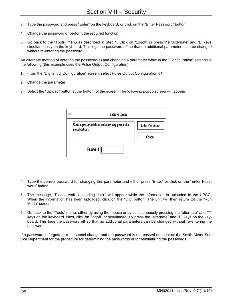
Section VIII – Security
MN02011 Issue/Rev. 0.7 (11/10) 50
3. Type the password and press “Enter” on the keyboard, or click on the “Enter Password” button.
4. Change the password or perform the required function.
5. Go back to the “Tools” menu as described in Step 1. Click on “Logoff” or press the “Alternate” and “L” keys simultaneously on the keyboard. This logs the password off so that no additional parameters can be changed without re-entering the password.
An alternate method of entering the password(s) and changing a parameter while in the “Configuration” screens is the following (this example uses the Pulse Output Configuration):
1. From the “Digital I/O Configuration” screen, select Pulse Output Configuration #1.
2. Change the parameter.
3. Select the “Upload” button at the bottom of the screen. The following popup screen will appear:
4. Type the correct password for changing this parameter and either press “Enter” or click on the “Enter Pass-word” button.
5. The message, “Please wait. Uploading data.” will appear while the information is uploaded to the UPCC. When the information has been uploaded, click on the “OK” button. The unit will then return tot the “Run Mode” screen.
6. Go back to the “Tools” menu, either by using the mouse or by simultaneously pressing the “alternate” and “T” keys on the keyboard. Next, click on “logoff” or simultaneously press the “alternate” and “L” keys on the key-board. This logs the password off so that no additional parameters can be changed without re-entering the password.
If a password is forgotten or personnel change and the password is not passed on, contact the Smith Meter Ser-vice Department for the procedure for determining the passwords or for reinitializing the passwords.
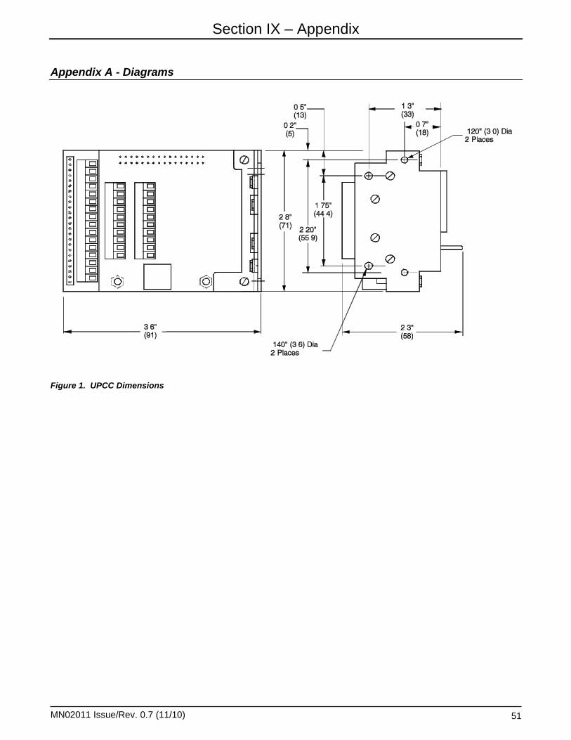
Section IX – Appendix
MN02011 Issue/Rev. 0.7 (11/10) 51
Appendix A - Diagrams
Figure 1. UPCC Dimensions

Section IX – Appendix
MN02011 Issue/Rev. 0.7 (11/10) 52
Figure 2. Explosion Proof Housing Dimensions

Section IX – Appendix
MN02011 Issue/Rev. 0.7 (11/10) 53
Size 3" 4" 6" 8" 10" 12" 16"
A 17.5 (445)
18.9 (480)
21.1 (536)
23.1 (587)
25.3 (643)
27.3 (693)
30.5 (775)
B 15.5 (394)
17.0 (432)
19.0 (483)
21.5 (546)
24.0 (610)
27.0 (686)
31.5 (800)
Figure 3. Factory-Mounted Envelope Dimensions for 150# Flanged Meters with Dual Pickup Coils

Section IX – Appendix
MN02011 Issue/Rev. 0.7 (11/10) 54
Size 3" 4" 6" 8" 10" 12" 16"
A 14.4 (366)
15.8 (401)
17.9 (455)
20.2 (513)
22.5 (572)
25.0 (635)
28.9 (734)
B 7.5
(191) 9.0
(228) 11.0 (279)
13.5 (343)
16.0 (406)
19.0 (483)
23.5 (597)
Figure 4. Factory-Mounted Envelope Dimensions for 150# Flanged Meter with Single Pickup Coil

Section IX – Appendix
MN02011 Issue/Rev. 0.7 (11/10) 55
Figure 5. Jumper Locations (Revision 8 and lower Assemblies)

Section IX – Appendix
MN02011 Issue/Rev. 0.7 (11/10) 56
Figure 6. Switch Locations (Revision 9 and higher Assemblies)

Section IX – Appendix
MN02011 Issue/Rev. 0.7 (11/10) 57
Figure 7. Daughter Board J1 Connector.
Note: Jumper Wires only required for Rev. 8 and older Assemblies ….i.e. boards with plug jumpers located on the edge of the board, boards with switches have connection made through the header connector, the jumper wires are not required. All remaining illustrations in the appendices assume older board assemblies and show jumper wires installed.

Section IX – Appendix
MN02011 Issue/Rev. 0.7 (11/10) 58
Figure 8. Daughter Board J2 Connector
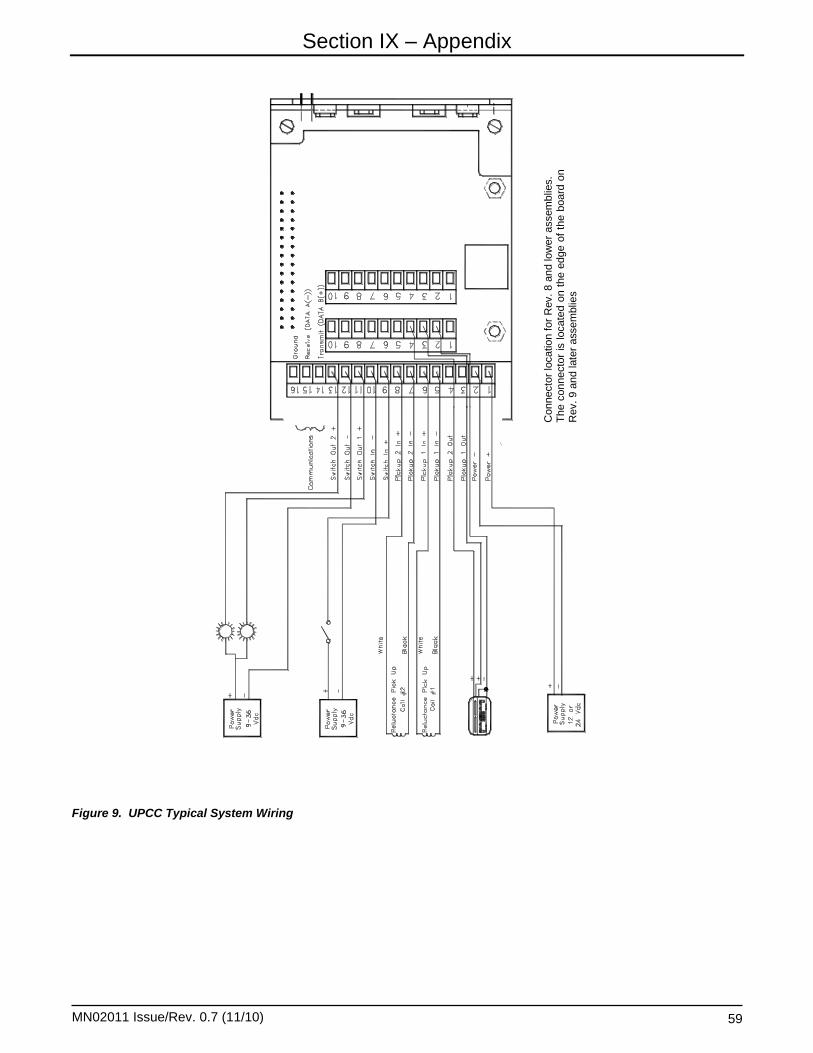
Section IX – Appendix
MN02011 Issue/Rev. 0.7 (11/10) 59
Figure 9. UPCC Typical System Wiring
Connecto
r lo
catio
n f
or
Rev. 8 a
nd lo
wer
assem
blie
s.
Th
e c
onnecto
r is
locate
d o
n t
he e
dge o
f th
e b
oard
on
R
ev.
9 a
nd late
r assem
blie
s

Section IX – Appendix
MN02011 Issue/Rev. 0.7 (11/10) 60
Figure 10. UPCC Typical Wiring with Square Wave Input

Section IX – Appendix
MN02011 Issue/Rev. 0.7 (11/10) 61
Figure 11. UPCC EIA-232 Communications Wiring

Section IX – Appendix
MN02011 Issue/Rev. 0.7 (11/10) 62
Figure 12. UPCC EIA-485 Communications

Section IX – Appendix
MN02011 Issue/Rev. 0.7 (11/10) 63
Figure 13. Typical Daisy Chain Communications Wiring Scheme

Section IX – Appendix
MN02011 Issue/Rev. 0.7 (11/10) 64
Figure 14. UPCC EIA-485 Communications with Modem

Section IX – Appendix
MN02011 Issue/Rev. 0.7 (11/10) 65
Figure 15. UPCC EIA-232 Communications with Modem

Section IX – Appendix
MN02011 Issue/Rev. 0.7 (11/10) 66
Figure 16. UPCC Solartron Viscometer Head Wiring (Common Power Supply)

Section IX – Appendix
MN02011 Issue/Rev. 0.7 (11/10) 67
Figure 17. UPCC Solartron Viscometer Head Wiring (Separate Power Supply)

Section IX – Appendix
MN02011 Issue/Rev. 0.7 (11/10) 68
Figure 18. UPCC DS1820 Temperature Sensor Wiring
Figure 19. UPCC 4-20 mA Input Wiring

Section IX – Appendix
MN02011 Issue/Rev. 0.7 (11/10) 69
Figure 20. UPCC 4-20 mA Output Wiring

Section IX – Appendix
MN02011 Issue/Rev. 0.7 (11/10) 70
Appendix B - Sample Solartron Calibration Certificate

Section IX – Appendix
71 MN02011 Issue/Rev. 0.7 (11/10)
Appendix C - Present Values Report

Section IX – Appendix
MN02011 Issue/Rev. 0.7 (11/10) 72

Section IX – Appendix
MN02011 Issue/Rev. 0.7 (11/10) 73

Section IX – Appendix
MN02011 Issue/Rev. 0.7 (11/10) 74

Section IX – Appendix
MN02011 Issue/Rev. 0.7 (11/10) 75
Appendix D - Batch History Report

Section IX – Appendix
MN02011 Issue/Rev. 0.7 (11/10) 76
Appendix E - Configuration Report

Section IX – Appendix
MN02011 Issue/Rev. 0.7 (11/10) 77

Section IX – Appendix
MN02011 Issue/Rev. 0.7 (11/10) 78
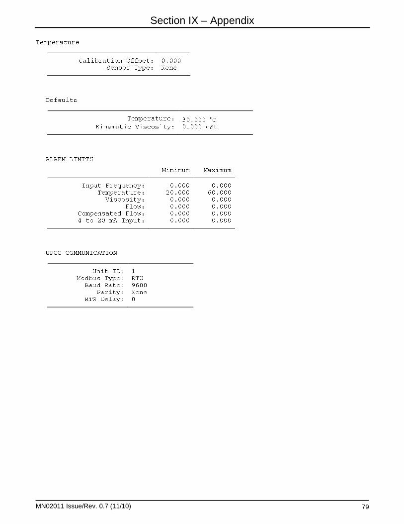
Section IX – Appendix
MN02011 Issue/Rev. 0.7 (11/10) 79

Section IX – Appendix
MN02011 Issue/Rev. 0.7 (11/10) 80

Section IX – Appendix
MN02011 Issue/Rev. 0.7 (11/10) 81

Section IX – Appendix
MN02011 Issue/Rev. 0.7 (11/10) 82
Appendix F - Alarm History Report

Section X – Index
MN02011 Issue/Rev. 0.7 (11/10) 83
4-20 mA Configuration, 32 4-20 mA Input, 33, 68 4-20 mA Inputs, 45 4-20 mA Outputs, 32 4-20mA Outputs, 44 About UPCC, 18 Access, 11
Alarm Acknowledgment/Reset, 31, 45 Alarms, 10, 30, 37
ASCII, 6, 40 Batch Average, 43 Batch Averages, 42
Batch End, 31, 45 Baud Rate, 6, 40 Bidirection Mode, 25, 41
Clear Latched Alarms, 30
Close, 11, 17 Communications, 4, 10, 40, 61, 62, 63, 64, 65
Comp Mul Flow Rate, 32
Comp Mult., 42
Comp Flow Rate, 44 Company Name, 19
Compensated Multiplier, 42
Compensated * Multiplier, 43 Compensated Flow, 39
Compensated pulses, 42
Compensated Pulses, 26, 43, 71
Compensated Pulses* Multiplier, 26 Compensation, 25, 27, 43, 72
Compensation Type, 25
Confirm, 11 Constant, 2 Constant entry options, 27
Daisy Chain, 4, 63 Date and Time, 11
Daughter Board J1 Connector, 57
Daughter Board J2 Connector, 58 Defaults, 36 Density, 33, 34, 42, 44, 70 Density Units, 34
Description, 17 Digital I/O Configuration, 30, 42, 45 Digital Inputs, 45 Digital Outputs, 45
Direct Entry of Constants, 27
Disabled, 26, 32, 42, 43, 44
DS1820, 36, 68 Dual Pulse Security, 26 Dynamic Viscosity, 34, 35, 44 Dynamic Viscosity Units, 35 End Batch, 11
EPROM CRC Failure, 30 Factors, 23
Factory-Mounted Envelope Dimensions, 53, 54
Failed Temperature Input, 31
Failed Viscometer Input, 31 Firmware Version, 19 Flow, 22
Flow Direction, 43, 45, 71 Flow Rates, 43, 72 Frequency, 42 Gain, 32 General, 10, 19, 23, 32, 36, 37, 42, 43 Hardware, 2 High (Maximum) Engineering Value, 32
Housing Dimensions, 51, 52 Identification, 19
Input Contact, 25 Input Contact Mode Configuration, 31 Input Frequency Alarm, 30, 31, 37 Instantaneous, 43
Invalid Configuration CRC, 31
Invalid Power Foil CRC, 30
Jumper Locations, 55
K-Factor, 23, 37, 71
Kinematic Viscosity, 32, 34, 35, 42, 44 Label, 27 Low (Minimum) Engineering Value, 32
Main Board 16-Pin Connector, 56
Maximum 4 to 20 mA Input Alarm Limit, 31
Maximum Compensated Flow Alarm Limit, 31
Maximum Delta Frequency, 22
Maximum Flow Alarm Limit, 31
Maximum Input Frequency Alarm Limit, 31
Maximum Input Frequency Exceeded, 30
Maximum Output Slew Rate, 22
Maximum Temperature Alarm Limit, 31
Maximum Viscosity Alarm Limit, 31 Meter, 42 Meter Diameter (Size), 21
Meter Direction, 31 Meter Flow Ranges, 38 Meter ID, 19, 71 Meter Location, 19 Meter Profile, 27, 41, 71
Minimum Compensated Flow Alarm Limit, 30
Minimum Flow Alarm Limit, 30
Minimum Input Frequency Alarm Limit, 30
Minimum Temperature Alarm Limit, 30
Minimum Viscosity Alarm Limit, 30
Missing Pulse Alarm, 30
Missing Pulse B Alarm, 31
Modbus Address, 17 Modbus Type, 6, 40 Mode, 32 Modes, 25
No Flow Frequency, 22
No-Flow Condition, 31, 44, 71 Non-Resettable Pulse Totals, 43, 72 Number of Blades, 21
NV RAM CRC Failure, 31
Off, 25 Offset, 33 Operating Principle, 2 Operating Range, 20 Output Contact Configuration, 30 Parameter Entry, 11 Parity, 6, 40 Password, 11 Password Editor, 11 Pickup Coil Connection, 25 Point to Point., 4 Present Batch Information, 41, 71 Present Value, 41 Profiles, 27 Programming Individual I.D. Number to UPCC, 5 Pulse Multiplier, 71
Quadrature, 25
RAM Failed Self-Test, 30
Raw echo of input pulses, 26, 42, 43

Section X – Index
MN02011 Issue/Rev. 0.7 (11/10) 84
Raw Flow, 37
Raw Flow Rate, 32, 44
Raw Pulse Multiplier, 42
Raw Pulse * Multiplier, 43
Raw Pulse* Multiplier, 26 Raw Pulses, 41
Read From Meter, 17 Reduced Op Mode, 44, 71 Reset Cumulative Totalizer, 11
RTD, 36 RTS Delay, 6
RTU, 4, 6, 40 Run Mode, 17, 30, 33, 34 Scaling Factors, 34 Security, 11, 26, 46 Security Code, 46, 47 Security Codes, 11 Set, 11 SMI Load Printer Installed, 21 Startup Procedures, 4 Status, 44 Status Input, 11
Supervisor, 11 Switch Output, 11 Temperature, 2, 20, 25, 28, 32, 36, 37, 42, 43, 44, 68, 70,
72 Temperature/Viscosity Input, 2 Ticket Number, 41, 71 Time, 2, 11, 20, 41, 45, 70, 71
Unit ID, 6, 40 Unit ID Number, 6 Units, 19, 23, 38
UPCC 4-20 mA Input Wiring, 68
UPCC 4-20 mA Output Wiring, 69
UPCC Dimensions, 51
UPCC DS1820 Temperature Sensor Wiring, 68
UPCC EIA-232 Communications, 61, 65
UPCC EIA-232 Communications Wiring, 61
UPCC EIA-485 Communications, 62, 64 UPCC Setup, 40
UPCC Solartron Viscometer Head Wiring, 67
UPCC Typical System Wiring, 59
UPCC Typical Wiring with Square Wave Input, 60, 61 UPCCMate, 5, 6, 7, 8, 9, 11, 12, 14, 16, 17, 40
Value, 17 Value Editor, 17
Viscometer, 2, 25, 36, 45, 66 Viscometer Input, 2 Viscometer Range Constants, 36 Viscosity, 33 Viscosity Correction Factor, 44 Volume, 20, 23, 42, 71 Weights and Measures, 11, 21, 31, 44
Weights and Measures Mode, 31
Weights and Measures Program Mode, 31
Write to Meter, 17

Section X – Index
MN02011 Issue/Rev. 0.7 (11/10) 85

Section XI – Related Publications
Printed in U.S.A. © 6/04 FMC Technologies Measurement Solutions Inc. All rights reserved. MN02011 Issue/Rev. 0.7 (11/10)
The following literature can be obtained from FMC Technologies Measurement Solutions Literature Fulfillment at [email protected] or online at www.fmctechnologies.com/measurementsolutions. When requesting literature from Literature Fulfillment, please reference the appropriate bulletin number and title.
UPCC Specification .......................................................................................................................... Bulletin SS02017 Installation/Operation ............................................................................................................. Bulletin MN02011 Communication ...................................................................................................................... Bulletin MN02012L
Revisions included in MN02011 Issue/Rev. 0.7 (11/10): Page 1: Safety Precautions updated with ATEX and IEC Ex Certifications.