repositorio.ufpe.br · universidade federal de pernambuco centro de informÁtica:...
TRANSCRIPT

Pós-Graduação em Ciência da Computação
Core Assets Development in Software Product Lines - Towards a Practical Approach for the
Mobile Game Domain
by
Leandro Marques do Nascimento
M.Sc. Dissertation
Universidade Federal de Pernambuco [email protected]
www.cin.ufpe.br/~posgraduacao
RECIFE, AUGUST/2008

UNIVERSIDADE FEDERAL DE PERNAMBUCO
CENTRO DE INFORMÁTICA
PÓS‐GRADUAÇÃO EM CIÊNCIA DA COMPUTAÇÃO
LEANDRO MARQUES DO NASCIMENTO
“CORE ASSETS DEVELOPMENT IN SOFTWARE PRODUCT LINES ‐ TOWARDS A PRACTICAL APPROACH FOR THE MOBILE
GAME DOMAIN"
ESTE TRABALHO FOI APRESENTADO À PÓS-GRADUAÇÃO EM CIÊNCIA DA COMPUTAÇÃO DO CENTRO DE INFORMÁTICA DA UNIVERSIDADE FEDERAL DE PERNAMBUCO COMO REQUISITO FINAL PARA OBTENÇÃO DO TÍTULO DE MESTRE EM CIÊNCIA DA COMPUTAÇÃO.
ORIENTADOR: SILVIO ROMERO DE LEMOS MEIRA CO-ORIENTADOR: EDUARDO SANTANA DE ALMEIDA
RECIFE, AGOSTO/2008
Nascimento, Leandro Marques do Cores assets development in software product lines - towards a practical approach for the mobile game domain / Leandro Marques do Nascimento. – Recife: O Autor, 2008. xiii, 128 folhas : il., fig. Dissertação (mestrado) – Universidade Federal de Pernambuco. CIn. Ciência da Computação, 2008.
Inclui bibliografia e glossário.
1. Ciência da computação. 2. Engenharia de software. I. Título. 004 CDD (22.ed.) MEI2008-096

“The journey of a thousand miles begins with a single step.”
Lao Tzu


A cknowledgements
One of the most encouraging phrases I have listened from Silvio Meira says:
“Nothing beats hard work”. This phrase translates all my feeling at the right
moment I finished this work and I may have no words to describe my gratitude
to all the people that helped me during this journey. Unfortunately, someone
may be forgotten and, for those not listed here, I humbly ask for their apologies
and understanding that it was not caused intentionally, but due to tricks played
by memory.
Initially, I would like to warmly thank my family, specially my parents
and my lovely fiancée. Without their caress, attention and incentive, I would not
have reached this point.
Additionally, I would like to thank my friend and co-advisor Eduardo
Almeida for helping me out with all my questions and guiding me through this
work. He, in agreement with Silvio Meira, was the one who most encouraged me
to apply for the M.Sc. program at Federal University of Pernambuco.
Next, I would not forget to thank all the members of the Reuse in
Software Engineering (RiSE) group. From the beginning until the very ending of
this work, they have been very supportive, sharing their knowledge and
fomenting discussions that helped me a lot with all the content of this
dissertation.
This work was partially funded by Recife Center for Advanced Studies
and Systems – C.E.S.A.R, which offered me a great environment to work, learn
and practice my knowledge in software reuse area. Besides, this work has been
possible thanks to Meantime Mobile Creations, which provided me all the
artifacts used in the experimental study performed in this dissertation. Special

iv
thanks to Tarcísio Câmara, from Meantime Mobile Creations, who gave me
precious information about mobile games development in practice.
My personal gratitude to all the fellows at C.E.S.A.R, especially the
Motorola iDEN team. Working with them is an enjoyable everyday activity.
Moreover, I would like to thank some key researchers in the software
reuse area, Bill Frakes, Dirk Muthig and Jan Bosch, for spending a bit of their
time in Brazil to take a look at my work and contribute with valuable feedback.
During my final presentation of this work, I received valuable feedback
from the reviewers André Santos and Uirá Kulesza, and from my advisor Silvio
Meira. Thank you all for dedicating your attention to review this work and
providing great comments with interesting discussions.
Thanks to the old school friends for being so present and providing me
moments of joy and happiness. These moments have been so important to
renew my disposition to keep working. My parties, summers, jokes and talks
would not have been so funny without them.
And last but not least, I want to thank God for giving me strength and
illuminating my entire path to the end of this dissertation.
Leandro Marques do Nascimento
Recife, Pernambuco, Brazil
August 25, 2008
A bstract
The most aimed objectives in software engineering are basically high
productivity, with high quality at low costs and one possible way for achieving
these objectives is establishing software reuse – the process of creating software
systems from existing software rather than building them from scratch. In this
context, one approach that can enable software reuse in practice is Software
Product Line (SPL) – a set of software-intensive systems sharing a common,
managed set of features that are developed from a common set of reusable core
assets in a prescribed way. A particular domain where the adoption of such
approach may bring relevant benefits is the mobile game domain mainly
because the games need to run in a big diversity of handsets and there is a big
number of games of the same type being developed with common features.
However, the characteristics of the mobile game domain usually create
barriers to apply SPL processes in practice, such as, restrictions of memory and
application size and different API implementations by different manufacturers.
In addition, the current SPL processes still lack of details on the phases related
to core assets implementation, making it difficult to properly handle the
mentioned characteristics of the domain in question.
Thus, this work aims at defining a practical approach for implementing
core assets in a SPL applied to the mobile game domain based on the good
practices from the state-of-the-art in the area. Moreover, in order to evaluate
the approach, an experimental study is performed using three platform-based
mobile games to build a SPL and, finally, a fourth game is derived from the SPL.
Keywords: software reuse, software product line, core assets
implementation, mobile game, experimental study.
R esumo
Os mais almejados objetivos da engenharia de software são basicamente alta
produtividade, com alta qualidade a um baixo custo e uma possível forma de
atingi-los é estabelecer reuso de software – o processo de criar sistemas de soft-
ware a partir de sistemas existentes ao invés de criar do início. Neste contexto,
uma abordagem que pode habilitar reuso na prática é Linha de Produto de Soft-
ware (LPS) – um conjunto de sistemas de software que compartilham um con-
junto comum e gerenciado de funcionalidades que satisfazem uma necessidade
específica de um domínio, e que são desenvolvidas a partir de um conjunto de
artefatos reusáveis. Um domínio em particular onde a adoção de tal abordagem
pode trazer benefícios é o domínio de jogos móveis principalmente porque os jo-
gos precisam executar em diversos dispositivos e existe uma grande quantidade
de jogos do mesmo tipo sendo desenvolvidos com funcionalidades em comum.
Entretanto, as características do domínio de jogos móveis geralmente
criam barreiras para os processos de LPS na prática, tais como, restrições de
memória e de tamanho da aplicação e diferentes implementações de API feitas
por diferentes fabricantes. Além disso, os atuais processos de LPS ainda care-
cem de detalhes em fases relacionadas à implementação de artefatos reusáveis,
dificultando a administração apropriada das características mencionadas.
Dessa forma, este trabalho objetiva definir uma abordagem prática para
implementação de artefatos reusáveis em uma LPS para o domínio de jogos mó-
veis com base nas boas práticas do estado da arte na área. Além disso, com a in-
tenção de avaliar a abordagem, um estudo experimental foi executado com três
jogos de plataforma para construir a LPS e um quarto jogo foi derivado dela.
Palavras-chave: reuso de software, linha de produto de software,
implementação de artefatos reusáveis, jogos móveis, estudo experimental.
T able of Contents
ACKNOWLEDGEMENTS ............................................................... III RESUMO ......................................................................................... V ABSTRACT .....................................................................................VI TABLE OF CONTENTS .................................................................. VII LIST OF FIGURES............................................................................X LIST OF TABLES............................................................................ XI LIST OF ACRONYMS .................................................................... XII 1. INTRODUCTION ..........................................................................1
1.1. MOTIVATION ..............................................................................................3 1.2. PROBLEM STATEMENT.................................................................................5 1.3. OVERVIEW OF THE PROPOSED SOLUTION .....................................................6 1.4. OUT OF SCOPE ............................................................................................ 7 1.5. ORGANIZATION OF THE DISSERTATION ........................................................8
2. SOFTWARE PRODUCT LINE CONCEPTS .................................... 9
2.1. SOFTWARE REUSE..................................................................................... 10 2.2. SOFTWARE PRODUCT LINES (SPLS)........................................................... 12
2.2.1. What Software Product Lines are not............................................ 14 2.2.1.1. Fortuitous Small-Grained Reuse........................................... 14 2.2.1.2. Single System Development with Reuse ............................... 14 2.2.1.3. Just Component-Based Development................................... 15 2.2.1.4. Just a Reconfigurable Architecture ....................................... 15 2.2.1.5. Releases and Versions of Single Products............................. 15 2.2.1.6. Just a Set of Technical Standards.......................................... 16
2.3. BENEFITS OF SOFTWARE PRODUCT LINES .................................................. 16 2.3.1. Enhancement of Quality ................................................................ 16 2.3.2. Reduction of Maintenance Effort .................................................. 16 2.3.3. Reduction of Development Costs................................................... 17 2.3.4. Reduction of Time to Market......................................................... 17 2.3.5. Improving Cost Estimation............................................................ 18 2.3.6. Benefits for the Customers............................................................. 18
2.4. MATURITY AND EVOLUTION IN SOFTWARE PRODUCT LINES........................ 19
viii
2.5. SUCCESSFUL CASES IN SOFTWARE PRODUCT LINES .................................... 21 2.5.1. Philips.............................................................................................22 2.5.2. Hewlett-Packard (HP) ...................................................................23 2.5.3. Boeing.............................................................................................24 2.5.4. Nokia ..............................................................................................24
2.6. CHAPTER SUMMARY..................................................................................26 3. SOFTWARE PRODUCT LINE PROCESSES: A SURVEY...............27
3.1. COMPONENT-BASED DEVELOPMENT (CBD)...............................................28 3.1.1. Catalysis .........................................................................................28 3.1.2. UML Components..........................................................................29
3.2. DOMAIN ENGINEERING PROCESSES ........................................................... 31 3.3. SOFTWARE PRODUCT LINE PROCESSES ......................................................34
3.3.1. GenVoca and Object-Oriented Product Lines and Frameworks...35 3.3.2. Product Line Software Engineering (PuLSETM) ............................ 37 3.3.3. Family-Oriented Abstraction, Specification and Translation
(FAST) ............................................................................................39 3.3.4. The KobrA Approach .................................................................... 40 3.3.5. Component-Oriented Platform Architecting Method (CoPAM)...42 3.3.6. Software Product Lines by SEI ......................................................43 3.3.7. FORM’s Extension .........................................................................44 3.3.8. Product Line UML-Based Software Engineering (PLUS) ..............45 3.3.9. Software Product Line Engineering (SPLE) Framework ..............46
3.4. SUMMARY OF THE STUDY...........................................................................47 3.5. CHAPTER SUMMARY..................................................................................50
4. CORE ASSETS DEVELOPMENT IN SOFTWARE PRODUCT LINES - TOWARDS A PRACTICAL APPROACH FOR THE MOBILE GAME DOMAIN......................................................................................... 51
4.1. INTRODUCTION .........................................................................................52 4.2. CORE ASSETS DEVELOPMENT IN SOFTWARE PRODUCT LINES - TOWARDS A
PRACTICAL APPROACH FOR THE MOBILE GAME DOMAIN ............................54 4.2.1. Component Modeling ....................................................................59 4.2.2. Component Implementation .........................................................63 4.2.3. Component Testing........................................................................78
4.4. CHAPTER SUMMARY..................................................................................79 5. AN EXPERIMENTAL STUDY IN THE MOBILE GAME DOMAIN .... ..................................................................................................81
5.1. INTRODUCTION .........................................................................................82 5.2. THE EXPERIMENTAL STUDY ......................................................................84
5.2.1. The Definition ................................................................................84 5.2.1.1. Goal ........................................................................................84 5.2.1.2. Questions ...............................................................................85 5.2.1.3. Metrics ...................................................................................85
5.2.2. The Planning ..................................................................................87 5.2.3. The Project Used in the Study ...................................................... 90 5.2.4. The Instrumentation......................................................................92 5.2.5. The Operation ................................................................................92 5.2.6. The Analysis and Interpretation.................................................. 101

ix
5.2.7. Conclusions .................................................................................. 103 5.2.8. The Lessons Learned ................................................................... 104
5.3. CHAPTER SUMMARY................................................................................ 105
6. CONCLUSIONS ........................................................................106
6.1. RESEARCH CONTRIBUTIONS .................................................................... 107 6.2. RELATED WORK......................................................................................108 6.3. FUTURE WORK ....................................................................................... 110 6.4. ACADEMIC CONTRIBUTIONS ..................................................................... 111 6.5. CONCLUDING REMARKS ...........................................................................113
REFERENCES............................................................................... 114
L ist of Figures
FIGURE 1.1. THE RISE FRAMEWORK FOR SOFTWARE REUSE. ......................................4 FIGURE 2.1. COSTS FOR DEVELOPING N KINDS OF SYSTEMS AS SINGLE SYSTEMS
COMPARED TO PRODUCT LINE ENGINEERING....................................................... 17 FIGURE 2.2. TIME TO MARKET WITH AND WITHOUT PRODUCT LINE ENGINEERING. .... 18 FIGURE 2.3. MATURITY LEVELS FOR SOFTWARE PRODUCT LINES ............................... 19 FIGURE 3.1. CREATING INHERITANCE HIERARCHIES BY COMPOSING LAYERS..............36 FIGURE 3.2. REFINEMENTS HIERARCHIES AND FRAMEWORK INSTANCES ................... 37 FIGURE 3.3. PULSETM OVERVIEW...........................................................................38 FIGURE 3.4. KOMPONENT SPECIFICATION AND REALIZATION MODELS ....................... 41 FIGURE 3.5. PRODUCTS, METHODS AND FAMILIES ....................................................42 FIGURE 3.6. THREE ESSENTIAL ACTIVITIES ..............................................................44 FIGURE 3.7. DOMAIN ENGINEERING AND PRODUCT LINE PROCESSES TIMELINE. ........48 FIGURE 4.1. APPROACH OVERVIEW OF SPL DOMAIN IMPLEMENTATION STEP APPLIED
TO THE MOBILE DOMAIN. ...................................................................................55 FIGURE 4.2. EXAMPLE OF THE DOMAIN ARCHITECTURE FOR THE MOBILE GAME
DOMAIN. ...........................................................................................................58 FIGURE 4.3. EXAMPLE OF INTERNAL COMPONENT DESIGN (STRUCTURAL MODEL) WITH
THE USE OF VARIANT STEREOTYPE. .....................................................................62 FIGURE 4.4. EXAMPLE OF COMPONENT INTERNAL DESIGN WITH ADDITIONAL
INFORMATION OF THE APPLICABLE CONDITIONAL COMPILATION TAGS..................63 FIGURE 5.1. GQM HIERARCHICAL MODEL (BASILI ET AL., 1994)..............................83 FIGURE 5.2. SCREENSHOTS OF THE GAMES USED FOR THE EXPERIMENTAL STUDY. A)
MONGA. B) AMERICAN DAD – ROGER’S SCAPE. C) ZAAK..................................... 91 FIGURE 5.3. DOMAIN FEATURE MODEL. ...................................................................94 FIGURE 5.4. INTERNAL DESIGN OF THE ENEMY (AI) COMPONENT. ............................97 FIGURE 5.5. SMART ESCAPE APPLICATION FEATURE MODEL BASED ON THE DOMAIN
FEATURE MODEL..............................................................................................100 FIGURE 5.6. SMART ESCAPE’S MAIN GAME SCREEN.................................................100 FIGURE 6.1. ABSTRACTION LEVELS IN SOFTWARE PRODUCT LINES APPLIED TO MOBILE
GAME DOMAIN................................................................................................. 109

L ist of Tables
TABLE 4.1. EXAMPLE OF PRODUCT PORTFOLIO WITH PRIORITIES AMONG FAMILIES OF HANDSETS.........................................................................................................56
TABLE 4.2. EXAMPLE OF PRODUCT MAP ................................................................. 57 TABLE 4.3. EXAMPLE OF MAPPING OF HANDSET FAMILIES AND THEIR MAIN
CAPABILITIES IN THE PRODUCT MAP....................................................................58 TABLE 4.4. EXAMPLE OF PRODUCT MAP WITH CONDITIONAL COMPILATION TAGS
ATTACHED......................................................................................................... 61 TABLE 4.5. EXAMPLE OF MAPPING OF HANDSET FAMILIES, THEIR MAIN CAPABILITIES
AND THE RESPECTIVE CONDITIONAL COMPILATION TAGS ..................................... 61 TABLE 4.6. EXAMPLE OF COMPONENT DOCUMENTATION AFTER ITS
IMPLEMENTATION.. ...........................................................................................78 TABLE 4.7. SUMMARY OF THE APPROACH FOR CORE ASSETS DEVELOPMENT IN A SPL
APPLIED TO THE MOBILE GAME DOMAIN............................................................. 80 TABLE 5.1. PRODUCT PORTFOLIO WITH THREE MANUFACTURERS LISTED.................95 TABLE 5.2. PRODUCT MAP WITH CONDITIONAL COMPILATION TAGS ATTACHED. .......96 TABLE 5.3. GROUPS OF CONDITIONAL COMPILATIONS TAGS FOR THE FOUR
MANUFACTURERS DESCRIBED IN PRODUCT PORTFOLIO ........................................96 TABLE 5.4. BASIC DOMAIN ARCHITECTURE OVERVIEW ..........................................100 TABLE 5.5. COMPONENTS OVERVIEW. .................................................................. 101 TABLE 5.6. COMPONENT COMPLEXITY VALUES ..................................................... 101 TABLE 5.7. DOMAIN RESTRICTIONS MANAGEMENT VALUES ................................... 102 TABLE 5.8. TRACEABILITY VALUES ....................................................................... 103

L ist of Acronyms
ADL – ARCHITECTURE DESCRIPTION LANGUAGE.....................................................39 AI – ARTIFICIAL INTELLIGENCE ..............................................................................97 AML – APPLICATION MODELING LANGUAGE.......................................................... 40 AOP – ASPECT-ORIENTED PROGRAMMING............................................................. 60 API – APPLICATION PROGRAMMING INTERFACE ........................................................5 CBD – COMPONENT-BASED DEVELOPMENT .............................................................. 1 CBSE – COMPONENT-BASED SOFTWARE ENGINEERING.............................................6 CDC – CONNECTED DEVICE CONFIGURATION.......................................................... 77 CLDC – CONNECTED LIMITED DEVICE CONFIGURATION..........................................64 COPAM – COMPONENT-ORIENTED PLATFORM ARCHITECTING METHOD .................42 DE – DOMAIN ENGINEERING ....................................................................................9 DLL – DYNAMIC LINK LIBRARIES............................................................................64 DSL – DOMAIN-SPECIFIC LANGUAGE........................................................................ 1 DSSA – DOMAIN-SPECIFIC SOFTWARE ARCHITECTURE ...........................................38 FAST – FAMILY-ORIENTED ABSTRACTION, SPECIFICATION AND TRANSLATION.........39 FODA – FEATURE ORIENTED DOMAIN ANALYSIS ....................................................32 FORM – FEATURE-ORIENTED REUSE METHOD ...................................................... 31 GQM – GOAL QUESTION METRIC ...........................................................................82 GSM – GLOBAL SYSTEM FOR MOBILE COMMUNICATIONS...........................................3 HTTP – HYPERTEXT TRANSFER PROTOCOL ..............................................................2 IRS – INERTIAL REFERENCE SYSTEM ...................................................................... 21 JAR – JAVA ARCHIVE .............................................................................................56 JME – JAVA MICRO EDITION....................................................................................3 JSE – JAVA STANDARD EDITION ............................................................................. 77 JSR – JAVA SPECIFICATION REQUEST .....................................................................53 KOBRA – KOMPONENTENBASIERTE ANWENDUNGSENTWICKLUNG.............................. 7 MIDP – MOBILE INFORMATION DEVICE PROFILE....................................................56 OCL – OBJECT CONSTRAINT LANGUAGE..................................................................30 ODM – ORGANIZATION DOMAIN MODELING........................................................... 31 OFP – OPERATIONAL FLIGHT PROGRAM .................................................................24 OO – OBJECT ORIENTATION ...................................................................................35 OSGI – OPEN SERVICES GATEWAY INITIATIVE .........................................................33 PDA – PERSONAL DIGITAL ASSISTANT ....................................................................64 PLUS –PRODUCT LINE UML-BASED SOFTWARE ENGINEERING................................45 PULSE – PRODUCT LINE SOFTWARE ENGINEERING................................................... 7 RIDE – RISE PROCESS FOR DOMAIN ENGINEERING................................................. 31 RISE – REUSE IN SOFTWARE ENGINEERING ..............................................................4 RSEB - REUSE-DRIVEN SOFTWARE ENGINEERING BUSINESS.................................... 31
xiii
RUP – RATIONAL UNIFIED PROCESS.......................................................................29 SEI – SOFTWARE ENGINEERING INSTITUTE............................................................. 21 SPL – SOFTWARE PRODUCT LINE.............................................................................. 1 SPLE – SOFTWARE PRODUCT LINE ENGINEERING ...................................................46 UML – UNIFIED MODELING LANGUAGE..................................................................28 USDP – UNIFIED SOFTWARE DEVELOPMENT PROCESS ............................................45 XP – EXTREME PROGRAMMING ..............................................................................54
1 Introduction
“No great discovery was ever made without a bold guess”
Isaac Newton (1642 – 1726) English physicist and mathematician
One of the key factors for improving quality, productivity and consequently
reducing costs in software development is the adoption of software reuse – the
process of creating software systems from existing software rather than building
them from scratch (Krueger, 1992). Several research activities have been
performed in the software reuse area (Almeida et al., 2007a) involving different
aspects, such as: different techniques of programming, for example, generative
programming (Czarnecki & Eisenecker, 2000) and Domain-Specific Languages
(DSL) (Greenfield et al., 2004), which can make possible to automate code
generation; Component-Based Development (CBD) methods (Cheesman &
Daniels, 2001), (D'Souza & Wills, 2001), (Szyperski, 2002), which explore the
benefits of reusing software components; and reuse processes, considering a
systematic sequence of activities to enable the development for and with reuse
(Weiss & Lai, 1999), (Bayer et al., 1999), (Atkinson et al., 2000), (Clements &
Northrop, 2001), (Gomaa, 2005), (Pohl et al., 2005), (Almeida, 2007). Besides,
different efforts have been made to apply the concepts of this area in practice
with successful cases (SPL Hall of Fame, 2008), including big companies such
as Hewlett-Packard (HP), Bosch and Nokia.
An approach commonly cited in the software reuse area is Software
Product Line (SPL), which can be defined as “a set of software-intensive
Chapter 1 – Introduction
2
systems that share a common, managed set of features satisfying the specific
needs of a particular market segment or mission and that are developed from
a common set of core assets in a prescribed way” (Clements & Northrop, 2001).
In other words, a SPL allows new applications to be instantiated based on a set
of core assets, developed from the analysis of the commonalities and
variabilities of a specific domain or market segment.
Furthermore, a particular market segment that is in high-growth during
the last years is the mobile applications market, especially the mobile games.
According to iSuppli1, the prediction is that the worldwide mobile gaming
market will be worth $6.1 billion in 2010 – up from $1.8 billion in 2005.
However, this market involves much more complex challenges, mainly because
of the variety of handsets and manufacturers, many platform restrictions and
different hardware configurations. For example, a game produced by
Meantime2, called My Big Brother, had to be deployed for almost fifty devices
and the game had to support variations across those devices, such as: different
screen sizes, different ways of handling HTTP protocol and different keypad
configurations (Alves et al., 2005a). This scenario demands well defined
software processes to build applications compatible with as many handsets as
possible, considering the variabilities across handset platforms and possible
commonalities among various games in the same domain. Therefore, SPL can
be a suitable option in this case.
Different works have been published in the SPL area describing general
purpose processes applied to different contexts, from avionics (Sharp, 2000) to
consumer electronics (Ommering, 2002). However, considering the lack of
details of those processes in the core assets implementation phase, they can not
address properly the early mentioned restrictions of the mobile game domain.
Thus, the establishment of a SPL approach capable of handling those
restrictions is the main subject of this work. This chapter contextualizes the
focus of this work and starts by presenting its motivation with a clear definition
of the problem.
1 iSuppli Corporation: Applied Market Intelligence, available on http://www.isuppli.com/, accessed in January, 2008. 2 Meantime Mobile creations, available on http://www.meantime.com.br, accessed in January, 2008.

Chapter 1 – Introduction
3
1.1. Motivation Software reuse is generally regarded as the most important mechanism for
performing software development more efficiently (Krueger, 1992). The ideas
behind software reuse started to come up in the late 1960s, when McIlroy
(1968), motivated by the software crisis, wrote the so referenced paper on
software reuse entitled “Mass Produced Software Components”. Since that
time, many discussions took place, involving issues ranging from the possibility
of a software industrial revolution (Cox, 1990), in which programmers would
stop coding everything from scratch and begin assembling applications from
well-stocked catalogs of reusable software components, until silver bullets
(Moore, 2001) based on software reuse.
Several works have discussed the benefits of software reuse in terms of
improvements on productivity and software quality, and reduction on costs
(Lim, 1994), (Mili et al., 1995), (Basili et al., 1996), (Sametinger, 1997), (Frakes
& Succi, 2001), (Ezran et al., 2002), (Poulin, 2006). In addition, many
successful industrial cases of software reuse, specifically SPL (SPL Hall of Fame,
2008), involving, for example, Philips, Boeing, Nokia, Hewlett-Packard (HP),
General Motors, can indicate that those benefits are reachable.
On the other hand, one of the greatest motivations for this work is related
to the mobile domain. A picture of the mobile global market in 2008 reveals
that the number of mobile phones is about three billions, according to GSM
World3, and it is rapidly growing. This is only considering the GSM technology
and means that almost half the world population may possess a mobile phone.
Among these phones, Sun Microsystems4 estimates that at least half a billion of
them are Java-enabled. This last data shows that Java Micro Edition (JME)
(Java ME, 2008) is the most ubiquitous platform present in the mobile phones.
Immersed in this huge Java mobile world are the mobile games, which can be
considered the fastest growing “new” games sector, considering the prediction
that mobile gaming will be worth $6.1 billion by the end of this decade. So,
bringing SPL approach into the mobile game domain can improve productivity
3 GSM World - the website of the GSM Association, available on http://www.gsmworld.com/, accessed in January, 2008. 4 Sun Microsystems, available on http://www.sun.com/, accessed in January, 2008.

Chapter 1 – Introduction
4
and reduce costs in a promising area, possibly drawing attention of academia
and achieving good results in practice.
Besides those motivations, it is important to highlight that this work is
part of the Reuse in Software Engineering (RiSE) project5 (Almeida et al.,
2004), whose goal is to develop a robust framework for software reuse in order
to enable the adoption of a reuse program. The proposed framework has two
layers, as shows Figure 1.1. The first layer (on the left side) is formed by good
practices related to software reuse. Non-technical aspects, such as education,
training, incentives, program to introduce reuse, and organizational
management are considered. This layer constitutes a fundamental step before
the introduction of the framework in organizations. The second layer (on the
right side), is formed by important technical aspects related to software reuse,
such as processes, environment, and tools. This work is part of RiSE framework
in the second layer, specifically in the area of Software Reuse Process.
Figure 1.1. The RiSE framework for software reuse.
As can be seen in Figure 1.1, the RiSE project addresses reuse aspects not
included in the scope of this thesis, such as component search (Martins et al.,
2008), component testing (Silva et al., 2008), SPL architecture (Filho et al.,
2008) and SPL cost models (Nobrega et al., 2008), besides other aspects
covered by the project including reuse adoption strategies (Garcia et al., 2008a)
and assessment methods for software reuse capability (Garcia et al., 2008b).
5 The RiSE project in the web, available on http://www.rise.com.br, accessed in May, 2008.
Chapter 1 – Introduction
5
1.2. Problem Statement As stated by (Ezran et al., 2002), a process can be understood as a collection of
related tasks leading to a product. Another point of view describes simply a
software process as a way of defining specifically who does what, when, and how
(Fayad, 1997). In addition, a process is important to define how an organization
is supposed to perform its activities, and how people work and interact, in order
to ensure efficiency, reproducibility, and homogeneity (Ezran et al., 2002).
Different works discuss the benefits and improvements of using a well-defined
software process (Basili et al., 1995), (McConnell, 1998).
Specifically in the SPL area, different processes have been established in
order to systematically define the set of activities, steps, roles, inputs and
outputs within a SPL and then make possible the practical application of SPL
principles (Chapter 3 provides detailed discussions about those SPL processes).
In general, the SPL process can be divided in two distinct phases: core assets
development (or domain engineering) and product development (or application
engineering). During the first phase, the domain is analyzed taking into
consideration the possible existent applications, a reference architecture (or
domain architecture) is designed with the commonalities and variabilities in
domain, and then the core assets are implemented. In the second phase, the
reference architecture is instantiated and the already developed artifacts are
reused to create new applications. Throughout these two phases, management is
necessary to ensure the correct creation and usage of core assets (Clements &
Northrop, 2001).
Generally observing the relevant works in SPL processes area, it was
noticed that there is still a lack of details in the steps related to core assets
implementation (or domain implementation), such as: how domain features can
be mapped on components and correspondingly on code; how variability can be
managed in code level; which guidelines should be used to apply variability
implementation techniques. The lack of details in domain implementation
phases can make SPL approach unaffordable especially when it is taken into
account the restrictions of mobile game domain, such as memory size,
processing power, different screen sizes and different API implementations.

Chapter 1 – Introduction
6
Because of these characteristics involving the mentioned domain, the adoption
of a SPL should be supported by as many details as possible at code level.
Therefore, the main goal of this work can be stated as:
This work defines a practical approach for implementing core
assets in software product lines applied to the mobile game
domain (Java Micro Edition). Furthermore, it details the steps of
domain implementation, describing a set of activities, inputs,
outputs, guidelines and roles. Moreover, the work is based on the
good practices from the state-of-the-art in the area.
1.3. Overview of the Proposed Solution The practical approach for implementing core assets in software product lines
applied to the mobile game domain, mentioned in the last section, is based on
the following principles (in Chapter 4, the approach is discussed in details):
• Component-Based Development. The approach presents the
characteristics of the Component-Based Software Engineering (CBSE)
process model (Pressman, 2005), since reusable assets are used to
develop applications.
• Iterative and Incremental. The approach is iterative and incremental,
since it is important to divide the effort in iterations and increments in
order to more easily manage the activities.
• Domain-Specific Driven. The approach proposed by this work is
particularly tailored to be used in the mobile game domain.
Besides these principles, the approach focuses on core assets
implementation and is composed of three phases: component modeling,
component implementation, and component testing. In summary, component
modeling phase specifies the components’ internal design considering the
families of devices; component implementation uses a set of guidelines to
implement the specified components considering scenarios of the mobile game
domain; and, finally, component testing aims at documenting domain test cases
Chapter 1 – Introduction
7
and application-specific test cases, describing some guidelines on how to test
components in the mobile domain.
1.4. Out of Scope As the proposed approach of this work is part of a broader context, a set of
related aspects will be left out of its scope. The following issues are not directly
addressed by this work:
• Domain Analysis. In the description of this work, the domain analysis
phase is not considered in details. The good practices from other
processes were taken for this work as they reasonably attend to the need
of documenting and designing domain features. Moreover, there is
another work at RiSE group aiming directly at the issues related to
domain analysis phase (Lisboa et al., 2007).
• Domain Architecture. For the same reasons of domain analysis, the
domain architecture establishment is not detailed. The good practices
from PuLSE (Bayer et al., 1999) and KobrA (Atkinson et al., 2000)
processes (detailed in Chapter 3) attend the need of defining common
and variable points within the domain architecture.
• Component Identification. Identifying components in domain
architecture involves many other issues that do not belong to the scope of
this work. There are relevant researches in this area such as: (Kang et al.,
1998), (Almeida, 2007) and (Kim & Chang, 2004). Using techniques for
automatically identifying components in domain architecture can aid
domain architect when there is no domain expert present or the
architecture reaches a high level of complexity.
• Economics. Business aspects are an important instrument to aid
managers to start a software product line effort, since it can show the
return on investment in a specific domain. Nevertheless, it is not a trivial
issue. There is a specific work at RiSE group addressing economic aspects
of SPLs (Nobrega et al., 2008).
• Product Derivation. Once the SPL architecture is defined and the core
assets are implemented, the next step is to derive products by reusing this
Chapter 1 – Introduction
8
infrastructure (Pohl et al., 2005). This work does not provide many
details about product derivation steps, mainly because, at this point,
some tools can be used to aid on automatically deploying new products
from the SPL by choosing the domain features, such as FLiP (Calheiros et
al., 2007).
1.5. Organization of the Dissertation This document is organized as follows.
Chapter 2 presents a comprehensive history of software reuse with its
fundamentals and describes the basic concepts behind software product lines.
Examples of successful cases involving big companies which have adopted
software product lines are also provided.
Chapter 3 reviews nine relevant software product line processes and
mentions seven domain engineering processes, representing the state-of-the-art
in the area. The foundations, elements, and steps of the software product line
processes are also shown, depicting their strong and weak points.
Chapter 4 proposes a practical approach for implementing cores assets in
a software product line applied to the mobile game domain. The approach is
based on the good practices from other processes and on industrial experience,
taking into consideration the restrictions of the mobile domain, such as memory
size, processing power and limited application size.
Chapter 5 describes an experimental study in order to evaluate the
proposed approach. During the execution of the study, three different platform-
based mobile games are analyzed and an initial software product line is
established using the proposed approach. In addition, a fourth game is derived
from this SPL.
Chapter 6 is the last chapter in this dissertation. It summarizes the
contributions of this work, presents the related work and shows the directions
for future work.

2 Software Product Line Concepts
“Your theory is crazy, but it may not be crazy enough to be true”
Niels Bohr (1885 – 1962) Nobel Prize in Physics (1922), Danish theoretical physicist
A simple yet meaningful definition of software reuse is given by (Krueger, 1992):
“Software reuse is the process of creating software systems from existing
software rather than building software systems from scratch”. This definition
may seem easy to be implemented in practice, however software reuse has for
some times failed to become a standard software engineering practice (Krueger,
1992). Several approaches have been developed trying to make software reuse
feasible, such as: Component-Based Development (CBD) (D'Souza & Wills,
2001), (Cheesman & Daniels, 2001), (Almeida et al., 2007a), Domain
Engineering (DE) (Jacobson et al., 1997), (Villela, 2000), (Almeida, 2007b) and
Software Product Lines (SPLs) (Bayer et al., 1999), (Weiss & Lai, 1999),
(Clements & Northrop, 2001).
Among the cited approaches, software product lines have received
considerable adoption in the software industry and have proved to be a very
successful approach to intra-organizational software reuse (Bosch, 2002). In
this context, this chapter shows the basic concepts and ideas involved with
software product lines.
Chapter 2 – Software Product Line Concepts
10
In order to cover the basic software product line concepts, we briefly
discuss the concepts of software reuse and software components in Section 2.1.
Next, in Section 2.2, we present the definitions of a SPL and show examples of
what SPLs are not. The benefits of using the SPL approach are commented in
the Section 2.3. To help on understating the evolution path of an organization
which decides to adopt SPL, Section 2.4 describes the possible maturity levels
applied to a SPL, and, in the sequence, Section 2.5 brings four successful cases.
Finally, Section 2.6 presents a summary of this chapter.
2.1. Software Reuse Software reuse has been a goal in software engineering since 1968 (McIlroy,
1968), when the term software engineering was first coined. McIlroy defended
the idea that software components, usually compared to routines, should be
available in families arranged according to precision, robustness, generality and
performance. These component libraries allow components to be widely
applicable to different machines and users.
Nowadays, the benefits of using software components are widely known
and constructing large systems from small pieces can reduce the development
time and improve the final product quality (Szyperski, 2002).
Many definitions for a software component can be found in the literature.
After almost thirty years of McIlroy’s definition, (Sametinger, 1997) defined:
“Reusable software components are self-contained, clearly identifiable
artifacts that describe and/or perform specific functions and have clear
interfaces, appropriate documentation and a defined reuse status.”
Another definition well accepted by academia is from (Aoyama et al.,
2001, pp. 7): “A software component is a software element that conforms to a
component model and can be independently deployed and composed without
modification according to a component standard”. For Aoyama et al., “A
component model defines specific interaction and composition standards. A
component model implementation is the dedicated set of executable software
elements required to support the execution of components that conform to the
model”. They also define the software component infrastructure as “a set of
interacting software components designed to ensure that a software system or

Chapter 2 – Software Product Line Concepts
11
subsystem constructed using those components and interfaces will satisfy
clearly defined performance specifications”.
One satisfactory definition is presented by (Szyperski, 2002, pp. 41): “A
software component is a unit of composition with contractually specified
interfaces and explicit context dependencies only. A software component can
be deployed independently and is subject to composition by third parties.”
Considering the mentioned definitions, in traditional software reuse, a
library of reusable components is developed. This approach requires the
establishment of a library of reusable components and of an approach for
indexing, locating, and distinguishing among similar components (Prieto-Diaz
& Freeman, 1987). Some problems with this approach include managing the
large number of components that such a reuse library is likely to contain and
distinguishing among similar though not identical components.
The reusable component library is composed by the building blocks used
to construct the new system. Components are considered to be largely atomic
and ideally unchanged when reused, although some adaptations may be
required. Depending on the development approach, the library could contain
functional or object-oriented components (Nascimento et al., 2006).
An example of this traditional reuse is a subroutine library, which
consists of a collection of reusable subroutines in a given application area—for
example, a mathematical subroutine library. Another example is an object-
oriented toolkit, which consists of a set of related and reusable classes designed
to provide useful, general-purpose functionality.
Apart from certain specific domains, such as mathematical libraries, the
benefits of the traditional software reuse approach have been limited in general.
With this approach, overall reuse is relatively low, and the emphasis is on code
reuse.
Instead of reusing an individual component, it is much more
advantageous to reuse a whole design or subsystem, consisting of the
components and their interconnections (Gomaa, 2005). This means reuse of the
control structure of the application, including artifacts of requirements,

Chapter 2 – Software Product Line Concepts
12
architecture, code and tests. Thus, the reuse of such artifacts has much greater
potential than component reuse because it is large-grained reuse.
2.2. Software Product Lines (SPLs) According to (Gomaa, 2005): “The most promising approach for architecture
reuse is to develop a product line architecture, which explicitly captures the
commonality and variability in the family of systems that constitutes the
product line”. Different terms are used to refer to a SPL, such as a software
product family, a family of systems, or an application domain. Parnas referred
to a collection of systems that share common characteristics as a family of
systems (Parnas, 1978). According to Parnas, it is worth considering the
development of a family of systems when there is more to be gained by
analyzing the systems collectively rather than separately — that is, when the
systems have more features in common than features that distinguish them.
Nowadays, a family of systems is referred to as a Software Product Line
(SPL). According to (Clements & Northrop, 2001, pp. 05): “A Software Product
Line is a set of software-intensive systems sharing a common, managed set of
features, that satisfy the specific needs of a particular market segment or
mission and that are developed from a common set of core assets in a
prescribed way”. This definition puts constraints on the way systems in a SPL
are developed, mainly because substantial production economies can be
achieved when the systems in a SPL are developed from a common set of assets
in a prescribed way, in spite of being developed separately from scratch. Then,
these production economies can make SPLs attractive.
Other important contribution about SPLs is described by (Pohl et al.,
2005), which bring up the domain of automobiles to clarify the concepts. They
say that, formerly, goods were handcrafted for individual customers. By and by,
the number of people who could afford to buy various types of products
increased leading to Ford’s invention of the production line in the domain of
automobiles, which enabled production for a mass market much cheaper than
individual product creation. However, the production line reduced the
possibilities for diversification.
Chapter 2 – Software Product Line Concepts
13
Roughly, both types of products, individual and mass produced ones, can
be identified in the software domain as well: they are denoted as individual
software and standard software. Generally, each type of these products has its
drawbacks. Individual software products are rather expensive, while standard
software products lack sufficient diversification.
Once the customers got used to standardized mass products, they started
to want some kind of customization. Not all people want the same kind of car for
any purpose. For example, there are cars used for travelling by a single person,
others for big families. There are some cars that are used by people living in
cities, others mainly in the countryside. Thus, industry was confronted with a
rising demand for individualized products. This was the beginning of mass
customization, which is the large-scale production of goods tailored to
individual customers’ needs (Davis, 1987).
Combined with the concept of mass customization, (Pohl et al., 2005)
introduced the concept of platforms. At the side of the customer, mass
customization means the ability to have an individualized product. At the side of
the organization, mass customization means higher technological investments
which leads to higher prices for the individualized products and/or to lower
profit margins. Both effects are undesirable. Thus many organizations,
especially in the car industry, started to introduce common platforms for their
different types of cars by planning beforehand which parts will be used in
different car types. In this context, a platform is any base of technologies on
which other technologies or processes are built (Pohl et al., 2005).
Combining the concepts of mass customization and common platforms,
allows us to reuse a common base of technology and, at the same time, to bring
out products in close accordance with customers’ wishes. This systematic
combination for the development of software-intensive systems and software
products is what can be called software product line engineering (Pohl et al.,
2005). In this dissertation, the term software product lines will be used, since it
is widely accepted by universities and industry.

Chapter 2 – Software Product Line Concepts
14
2.2.1. What Software Product Lines are not For better understanding the definitions of software product lines, Clements &
Northrop enumerate some types of software reuse that should not be considered
as SPLs.
2.2.1.1. Fortuitous Small-Grained Reuse Past reuse agendas have focused on the reuse of relatively small pieces of code –
that is small-grained reuse. Organizations have built reuse libraries containing
algorithms, modules, objects, or components. Almost anything a software
developer writes goes into the library. Thus, other developers urged to use what
the library provides instead of creating their own versions. Unfortunately, it
often takes longer to locate these small pieces and integrate into the system than
it would take to build them from scratch. Many times, the documentation
involved with these small pieces does not explain how to generalize or adapt it
to other situations.
On the other hand, in a SPL approach, the reuse is planned, enabled, and
enforced – the opposite of opportunistic. All the assets are designed to be reused
and are optimized for use in more than a single system. The reuse in SPLs is
comprehensive and profitable.
2.2.1.2. Single System Development with Reuse A common situation in software engineering is when a team starts the
development of a new system and realizes that another system, very similar to
the one on development, had already been released. Then, the team borrows
what is possible from the previous effort, modifies it as necessary, adds
whatever it takes, and fields the new product. It has probably meant economic
advantage in comparison to the previous work, mainly because parts of another
system have been reused. However, this is ad hoc reuse.
There are two major differences between this approach and a software
product line approach: first, software product lines reuse assets that were
designed explicitly for reuse; and second, the product line is treated as a whole,
not as multiple products that are viewed and maintained separately.

Chapter 2 – Software Product Line Concepts
15
2.2.1.3. Just Component-Based Development Software product lines rely on a form of component-based development, but
much more is involved. The typical definition of component-based development
involves the selection of components from an in-house library or the
marketplace to build products. Although the products in software product lines
certainly are composed of components, these components are all specified by
the product line architecture. Moreover, the components are assembled in a
prescribed way, which includes exercising built-in variability mechanisms in the
components to put them in use in specific products.
2.2.1.4. Just a Reconfigurable Architecture Reference architectures and object-oriented frameworks are designed to be
reused in multiples systems and to be reconfigurable as necessary. A SPL
architecture is designed to support the variation needed by the products in the
product line, thus making it reconfigurable makes sense. But the product line
architecture is just one asset, even though an important one, in the product
line’s asset base.
Some authors also compare frameworks to software product lines
(Pasetti & Pree, 2000). In this specific case, we consider that frameworks can be
compared to SPLs if they explicitly model the commonality and variability
among the products involved.
2.2.1.5. Releases and Versions of Single Products Organizations routinely produce releases and versions of products. Each of
these new versions and releases is typically constructed using the architecture,
components, test plans, and other features of the prior releases. Considering
this context, a SPL product is different mainly because: first, it contains multiple
simultaneous products, all of which are going through their own cycles of
releases and versioning system; second, in a single-product context, once a
product is updated, there’s often no looking back, but in product lines an early
version of a product that is still considered to have market potential can easily
be kept as a viable member of the family.

Chapter 2 – Software Product Line Concepts
16
2.2.1.6. Just a Set of Technical Standards Many organizations set up technical standards to limit the choices their
software engineers can make regarding the kinds of sources of components to
incorporate the systems and different possible architecture forms, considering
different patterns in literature (Gamma et al., 1995). On the other hand, an
organization that undertakes a SPL effort may have such technical standards, in
which case the components and product line architecture will need to conform
to those standards. However, the standards are simply constraints that are
inputted to the SPL, no more.
2.3. Benefits of Software Product Lines As we described what software product lines are and what they are not, it is also
important to discuss a little about which are the benefits of applying such
approach. These benefits are shown in the following subsections and involve
technical and non-technical aspects.
2.3.1. Enhancement of Quality The artifacts in a SPL are reviewed and tested in many products. They have
worked properly in more than one type of product. The extensive quality
assurance across all the products in the SPL implies a significantly higher
chance of detecting faults and correcting them, thereby increasing the quality of
all products (Pohl et al., 2005).
2.3.2. Reduction of Maintenance Effort Considering that during the establishment of a software product line, the
artifacts are supposed to have higher quality since they are being reused and
tested across different products, we can conclude that less maintenance effort is
spent within these artifacts. Additionally, if an artifact has to be changed
because of an eventual error, the changes can be propagated to all products in
which the artifact is being used. The techniques used in product line engineering
make a system better maintainable as stated in (Coplien, 1998).
Chapter 2 – Software Product Line Concepts
17
2.3.3. Reduction of Development Costs Major changes in engineering practices are usually surrounded by economical
justification. An essential reason for introducing product line engineering is the
reduction of costs. When artifacts are reused in several systems, this implies a
cost reduction for each system. Obviously, before the artifacts can be reused,
they must be developed and this involves an up-front investment to create the
initial SPL infra-structure.
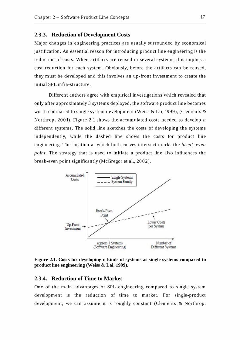
Different authors agree with empirical investigations which revealed that
only after approximately 3 systems deployed, the software product line becomes
worth compared to single system development (Weiss & Lai, 1999), (Clements &
Northrop, 2001). Figure 2.1 shows the accumulated costs needed to develop n
different systems. The solid line sketches the costs of developing the systems
independently, while the dashed line shows the costs for product line
engineering. The location at which both curves intersect marks the break-even
point. The strategy that is used to initiate a product line also influences the
break-even point significantly (McGregor et al., 2002).
Figure 2.1. Costs for developing n kinds of systems as single systems compared to product line engineering (Weiss & Lai, 1999).
2.3.4. Reduction of Time to Market One of the main advantages of SPL engineering compared to single system
development is the reduction of time to market. For single-product
development, we can assume it is roughly constant (Clements & Northrop,

Chapter 2 – Software Product Line Concepts
18
2001). For SPLs, the time to market indeed is initially higher, as the common
artifacts have to be built first. Yet, after having passed this initial difficulty, the
time to market is considerably reduced.
Figure 2.2. Time to market with and without product line engineering. (Pohl et al., 2005).
2.3.5. Improving Cost Estimation Once the core assets base used in a SPL is already built, it becomes easier for the
team involved to estimate the cost of new products. This happens mainly
because the team involved knows precisely what is needed to be done to
integrate the components in the base and what is needed to be implemented to
deploy a new functionality for a new product in the product line. Cost
estimations become as more precise as the product line reaches a higher level of
maturity.
2.3.6. Benefits for the Customers Customers obtain products adapted to their needs and wishes. However, in the
past it did not work like that because users had to adapt their own way of
working to the software. It often happened that customers had to get used to a
different user interface and a different installation procedure with each new
product. This annoyed them, is some situations, in particular as it even
happened when replacing one version of a product by the next version. Then,
users started to request for improved software ergonomics. In this context,
software product lines can bring great benefits for the customers. Firstly

Chapter 2 – Software Product Line Concepts
19
because customers can purchase these products at a reasonable price as product
line engineering helps to reduce the production costs. Additionally, customers
get higher quality products since the reusable components and their
configurations have been tested in many products developed earlier.
Moreover, despite possessing individual features, the products of a
product line have a lot in common due to the reused artifacts in the platform.
Similar user interfaces and similar major functionality make it easy for the
customer to switch from one product to another. The customer does not have to
learn new ways of using another product derived from the same platform.
2.4. Maturity and Evolution in Software Product Lines Adopting a SPL approach is not an easy task. It may take years for an
organization to reach acceptable maturity in a given domain and be a good
candidate for applying such approach (Bosch, 2002). Figure 2.3 shows one
possible way to understand the maturity levels of a software product line
proposed by (Bosch, 2002).
Figure 2.3. Maturity levels for software product lines (Bosch, 2002).
Chapter 2 – Software Product Line Concepts
20
Starting from a situation in which each product or application is
developed independently, the main maturity development path consists of:
• A standardized infrastructure: consists of the basic infrastructure based
on which new products are developed. This infrastructure is generally
composed of the operating system and the typical commercial
components on top of it, such as a database management system and a
graphical user interface. In addition, the organization may acquire some
domain-specific components from external sources. These components
are typically integrated through some proprietary glue code.
• A platform: it usually includes a standardized infrastructure and, on top
of that, it captures all functionality that is common to all products or
applications. The common functionality that is not provided by the
infrastructure is implemented by the organization itself, but typically the
application development treats the platform as if it was an externally
bought infrastructure.
• A software product line: once the benefits of exploiting the
commonalities among the products become more accepted within the
organization, there may be a consequent development in order to
increase the amount of functionality in the platform to the level where
functionality common to several, but not all, products become part of the
shared artifacts. Then, the stage of a software product line is reached.
• A configurable product base: at this stage, the organization, rather than
developing a number of different products, moves towards developing
only one configurable product base that, either at the organization or at
the customer site, is configured into the product bought by the customer.
Two additional developments can be identified, i.e. product populations
and a program of product lines. A product population approach is chosen when
the organization decides to increase the scope in terms of the number of
products. The program of product lines is selected when the scope of the
product line is extended in terms of the supported features (Bosch, 2002).
Chapter 2 – Software Product Line Concepts
21
Understanding which is the current maturity level of an organization and
which are the next levels to evolve can help on the SPL adoption. It is also
important to mention that the SPL adoption will likely fail if the levels are
skipped, for example, if an organization is using a standardized infrastructure
and tries to implement a configurable product base. Problems may happen
because deep organizational changes are needed and also because there are
several non-technical aspects involved, such as organization culture,
management commitment and funding, among others (Bosch, 2004).
2.5. Successful Cases in Software Product Lines There are many successful cases of software product lines application. In order
to recognize distinguished members of a community in a field of endeavor, the
Software Engineering Institute (SEI, 2008) established the SPL hall of fame
(SPL Hall of Fame, 2008). Each Software Product Line Conference (SPLC)
culminates with a session in which members of the audience nominate systems
for induction into the SPL Hall of Fame. Those nominations feed discussions
about what constitutes excellence and success in product lines. The goal is to
improve SPL practice by identifying the best examples in the field. Nominations
are voted on at the next SPLC by the majority of those present. The following
subsections show four cases of successful SPL application which have drawn
attention of academia and have been nominated to the hall of fame. The
subsections are arbitrarily ordered.
In spite of those successful examples, one particular failure case in the
software reuse area that is commonly mentioned is the Ariane 5 case (Jezequel
& Meyer, 1997). On June 4, 1996, the maiden flight of the European Ariane 5
launcher crashed, about 40 seconds after takeoff. Media reports indicated that a
half-billion dollars was lost. The failure was caused by an error occurred in the
Inertial Reference System (IRS) before takeoff. The IRS was reused from the
former versions of Ariane. According to the inquiry board a main lesson learned
of this fact was that reuse without a precise, rigorous specification mechanisms
can be a risk of potentially disastrous proportions.
Chapter 2 – Software Product Line Concepts
22
2.5.1. Philips Royal Philips Electronics of the Netherlands is one of the world’s biggest
electronics companies and the largest in Europe. Its products vary from
professional medical systems to lighting, consumer electronics, and domestic
appliances (Philips, 2008). Philips is one of the leading commercial European
researchers in the field of software product lines, with some successful
examples, such as the SPLs of consumer electronics (Ommering, 2000) and
medical imaging systems (Wijnstra, 2000).
In the field of consumer electronics, Philips’ portfolio includes audio–
video equipment, like TV-sets, radio receivers, CD and DVD players and
recorders, as well as set-top boxes (Philips, 2008). In this field, the customers
have high demands with respect to performance and due of the mass-market
nature, the cheapest memory and processor chips are used. Moreover, the
products have to be very reliable as they are offered in the mass market. Hence,
repairing them after delivery is very costly (Ommering et al., 2000).
In order to handle those specific characteristics of the early mentioned
field, the consumer electronics division has chosen to use a composition
paradigm in the production of the product lines. The methodology is named
Koala (Ommering, 2002). This means that the architecture has enough
flexibility to allow many different configurations of the same basic components.
The whole set of products is referred to as product populations, with many
differences and many commonalities. Components are combined to build more
complex components. Interfaces that do not match are connected through glue
code. Certain pieces of glue code are standard, and only need some parameters
to instantiate.
As a result to the Koala application, by 2002, all mid- and high-range TV
sets, and many other products as well, were produced in the population
(Ommering, 2004). Nowadays, there are 20 different software releases per year,
where each release serving 1-5 different product types. The product line
supports three different hardware platforms. As a good model to be followed,
the architecture did not need many adaptations after its first conception in
1996. This has proven that having a stable reference architecture is a major
advantage.
Chapter 2 – Software Product Line Concepts
23
On the other hand, in the field of medical imaging systems, Philips’
portfolio of medical systems includes products such as X-ray, ultrasonic or
computed tomography and services such as training, business consultancy, or
financial services (Philips, 2008). In order to handle with the increasing
complexity and diversity in this domain (Wijnstra, 2000), the medical systems
division has decided to employ a SPL approach. A medical middleware platform
serves as the basis for other software product lines in the company. Thus the
platform is a software product line in itself, which leads to additional variability
requirements for the platform. The component-based reference architecture
reuses existing software components that are transformed step by step into
domain artifacts. As a result, since 2001, the number of products that use the
common platform developed in the SPL has increased. By 2004, ten product
groups were based on the platform.
2.5.2. Hewlett-Packard (HP) HP is one of the world’s leading IT companies with many different business
areas, reaching from consumer handheld devices to powerful supercomputer
installations (HP, 2008). One reason that most contributed for HP to reach this
position was the reuse program, initiated in the early 1980s (Griss, 1994),
(Griss, 1995), and the adoption of a SPL approach (Toft et al., 2000).
One important business area is the manufacturing of printing technology.
HP must maintain a wide range of different firmware used in several products
for printing, copying, scanning, and faxing. In the late 1990s, HP initiated the
Owen Firmware Cooperative to install a software product line approach. Several
product teams build a community to provide the product line in a cooperative
way. Every product team adopts ownership of newly produced or significantly
changed core assets, so everyone feels responsible for the quality of the
platform. A small platform team ensures the robustness of the core assets and
guides the product teams in using the core assets (Toft et al., 2000).
The software product line approach yields a reuse rate of about 70% for
new products. About 20% of the application assets are based on slightly
modified core assets and only 10% require writing new code. Owen products

Chapter 2 – Software Product Line Concepts
24
have been produced using 25% of the staff, in 33% of the time, and with 96%
fewer bugs than earlier products.
2.5.3. Boeing The Boeing Company is one of the leading manufacturers of commercial
jetliners, military aircraft, satellites, missile defense, human space flight, and
launch systems (Boeing, 2008).
The Bold Stroke software product line was originally initiated in 1995 at
McDonnell-Douglas which, in the meantime, merged with the Boeing Company.
The purpose of the product line was to improve reuse potentials in the
Operational Flight Program (OFP) software across multiple fighter aircraft
platforms (Sharp, 2000). OFPs are mission-critical, distributed, real time
embedded applications supporting the avionics as well as the cockpit functions
for the pilot
The first step of introducing Bold Stroke included the definition of a
reference architecture and its proof of concept, including hardware, software,
standards, and practices. The main challenge when defining the reference
architecture was to harmonize the differences in the avionics subsystems,
mission computing hardware, and system requirements (Doerr & Sharp, 2000).
The success of the Bold Stroke software product line is based on the
reduction of dependencies between components and the dependency on
platform-specific hardware. The software design facilitates the modification of
components and maximizes the reuse in different OFPs (Doerr & Sharp, 2000).
The Bold Stroke software product line was flight tested successfully on several
different aircraft platforms hosted on different hardware configurations (Sharp,
2000).
2.5.4. Nokia Nokia is the world leader in mobile communication, holding approximately 40%
of the global mobile phone market (Nokia, 2008) and the company believes that
software product line engineering has helped them to reach that position. Every
year, approximately 30 different phones are manufactured to be distributed in
more than 130 countries. This scenario is quite challenging considering the

Chapter 2 – Software Product Line Concepts
25
main diversity Nokia’s product line must support, for instance, it must cover six
different protocol standards, 58 different languages, phones with a variable
number of keys, a wide variety of functional features and capabilities, different
user interface designs, and many platforms and environments (Heie, 2002).
Moreover, these features must be configurable and pluggable.
To establish its product line, Nokia is organized in software lines, which
are groups of people developing a specific set of features for a wide range of
products. Constantly, a new release is created by one group for others to use.
The company has different software lines for different levels of software, such
as, Digital Signal Processing (DSP), architecture, user interface, etc. Each
software line can potentially deliver to all products. Each deliverable must be
tested in as many configurations as possible. A global data base of feature
dependencies is maintained to ensure all affected parties are up-to-date on
changes. In fact, there is a lot of complexity involved with Nokia’s product line
considering backward compatibility, new technologies, operator requirements,
bugs, cultural values and so on (Heie, 2002).
One component that may exemplify the diversity of Nokia’s product line
is the language component. It must support about 58 different languages,
including non-Latin languages, such as, Chinese, Arabic, Korean, Hebrew and
Thai. Some of these languages are written from right to left. To complicate this
further, T9 optional feature must be supported. T9 feature helps the user to type
texts using the phone keyboard by guessing the word being typed without the
need of spelling that word letter by letter and not causing the user to press the
keys many times. What is more, when setting the phone language, all texts in
display must be automatically changed. To implement this component, they had
to separate language knowledge from the code – abstractly speaking, separate
appearance from behavior. They used the Observer design pattern and created a
text database where the texts are defined. Doing it this way, the texts are
resolved during display updates. As the main result, whatever language is
chosen, the code does not change, thus adding a language is transparent (Heie,
2002).
The initial software architecture for Nokia’s product line addressed
variations in hardware, communication standards, and user interfaces. The
Chapter 2 – Software Product Line Concepts
26
current architecture is component based on the client-server style. It allows
separate service providers to be plugged in or taken out without restarting the
system. This architecture supports both local and remote message passing and
component management, task scheduling and event control. Not so many
details about Nokia’s product line are provided because it constitutes a great
competitive advantage, some results of Nokia’s product line experience can be
seen in SPL Hall of Fame (SPL Hall of Fame, 2008).
2.6. Chapter Summary Software product line is a very successful approach to achieve software reuse
and, consequently, gains of productivity and quality and reduction of costs. This
chapter summarized the basic concepts about software reuse and software
product lines and presented the benefits of applying SPL approach. The chapter
also briefly introduced some levels of maturity in SPLs to help on the adoption
of such approach. At last, four successful cases of SPL application were shown
based on the SPL Hall of Fame.
Next chapter presents a survey on SPL processes, highlighting their way
to implement reusable assets, and discussing their strong and weak points.
These processes serve as a base for the approach proposed by this work.

3 Software Product Line Processes: A Survey
“I have no special talent. I am only passionately curious”
Albert Einstein (1879 – 1955) Nobel Prize in Physics (1921), German theoretical physicist
Although the reuse concept is not new (McIlroy, 1968), it is not a reality in
software factories yet, mainly because the practical application of software reuse
demands a systematic way of performing the organization’s activities (Morisio et
al., 2002). To face this problem, the adoption of a software reuse process is
recommended. It may help to clearly define the activities, responsibilities, roles,
artifacts, inputs and outputs of an entire organization, maintaining the focus on
the production of reusable artifacts in the end. There are several reuse processes
documented in literature since the early 1980s (Almeida et al., 2005). A
particular kind of such processes is concerned to handle issues about Software
Product Lines (SPLs), which has been revealed as a successful way of practicing
software reuse and achieving benefits such as productivity gains, cost reductions
and quality increases (SPL Hall of Fame, 2008).
The basic ideas about SPLs started to come up in 1992, when Batory &
O’Malley designed GenVoca (Batory & O’Malley, 1992), a method based on
generative programming which carries some aspects of SPL, such as an
extensible architecture. After that, two important publications came up with the
first SPL processes: PuLSETM (Bayer et al., 1999) and FAST (Weiss & Lai, 1999).
In this chapter, it will be introduced some of the most relevant SPL
processes found in literature from 1999 to 2007. In addition, it will be described
Chapter 3 – Software Product Line Processes: A Survey
28
important work published in the fields of Component-Based Development
(CBD) methods and Domain Engineering (DE) processes from the early 1980s
until 2007. Throughout the descriptions of these processes, their strong and
weak points are highlighted. At the end of this chapter, it might be possible to
understand better the state-of-the-art in the software reuse processes field.
This chapter is organized as follows: Section 3.1 describes three different
CBD methods; in sequence, Section 3.2 shows a summary of some important
domain engineering methods; SPL concepts and nine relevant processes are
explored in Section 3.3; Section 3.4 presents a summary of the study with a
timeline including all the processes and methods mentioned; and finally,
Section 3.5 brings a summary of the chapter.
3.1. Component-Based Development (CBD) The problems of developing software using the concepts involved with software
reuse and software components can be reduced by applying component-based
development methods, such as Catalysis (D'Souza & Wills, 2001) and UML
Components (Cheesman & Daniels, 2001). The following subsections present
more details about each of these CBD methods.
3.1.1. Catalysis Catalysis is a research initiative of University of Brighton in 2001, England, by
(D'Souza & Wills, 2001), which resulted in an integrated set of techniques to
build Object-Oriented Distributed Systems. According to the authors, Catalysis
is a component-based development method that covers all development phases
of a component, from its specification to its implementation.
This method is based on a set of principles for software development.
Among them, we can highlight: abstraction, precision, refinement, plug-
in components and some reuse laws.
The abstraction principle guides the developer to find essential aspects of
the system, avoiding irrelevant details for the context. The precision principle
aims to discover bugs and modeling inconsistencies. Successive refinements
between phase transactions help in obtaining more precise and reusable
artifacts. The plug-in components principle supports reusing components, with

Chapter 3 – Software Product Line Processes: A Survey
29
the objective of building others. And to complete, the main reuse law in
Catalysis is not reuse code without reusing its specification.
The software development method used in Catalysis is divided in three
phases: problem domain – elaborating “what” the system should do to solve
the problem; components specification – when the system behavior is
described; components internal design – when internal implementation
details of the components are specified. In this last phase, Catalysis lacks of
guidelines on how to apply variability implementation techniques
(Anastasopoulos & Gacek, 2001) within the components internal design.
Furthermore, the application of Catalysis may become problematic because it
does not establish a clear sequence of steps and does not clarify which are the
inputs and outputs for each phase in the process.
3.1.2. UML Components UML Components (Cheesman & Daniels, 2001) is CBD method based on UML
(OMG UML, 2007) extension, as the name itself, and was published in the same
year of Catalysis. UML Components makes use of UML extensions across its
phases. There are many different extension mechanisms for UML, but,
probably, the most used, according to (Cheesman & Daniels, 2001), are the
stereotypes, which can be attached to any element in UML diagrams.
There are six stereotypes of UML Components that can be added to
entities in a typical UML diagram: Type (<<type>>); Datatype (<<datatype>>);
Interface type (<<interface type>>); Component Specification (<<comp
spec>>); Offers (<<offers>>); and Core (<<core>>).
(Cheesman & Daniels, 2001) defined a workflow for component
development based on RUP (Jacobson et al., 1999). The workflow has the
following activities: Requirements, Specification, Provisioning,
Assembly, Test and Deployment. They correspond directly to RUP activities
except for the Specification activity, which is where the UML Components
concepts are applied. This activity is divided in three phases: Component
Identification, Component Interaction, and Component
Specification.

Chapter 3 – Software Product Line Processes: A Survey
30
In Component Identification phase, the steps to be followed are: identify
system interfaces and operations; create the business type model, which is like a
class diagram in a high-level of abstraction, including core types identification
(types that do not depend on any other); create initial component specification
and architecture; and specify component architecture. In the end of this phase,
initial component specifications are defined and organized into initial
component architecture. Existing systems and architectures are taken into
account. This phase should consider two kinds of contracts established between
entities and interfaces: usage and realization. The usage contract is the one
between a component object’s interface and its clients. The realization
contract is the contract between a component specification and its
implementation.
In the next phase, Component Interaction, the main goal is to discover
the business interfaces and operations and its respective signatures by analyzing
use cases and identifying the main interactions between the system and the
external user. Cheesman & Daniels suggest developing interaction models to aid
in operation identification, just as sequence diagrams in RUP.
This last phase, Component Specification, is focused on producing the
interface information model and building the component specification model
and architecture. If it is necessary to specify interfaces more precisely, based on
the operations discovery in the Component Interaction phase, then some
constraint language can be used, for example Object Constraint Language (OCL)
(OMG OCL, 2007). As result of this phase, interface specifications define usage
contracts and component specifications define realization contracts in the
component architecture.
Whenever Specification activity has been completed, including the three
phases described before, Provisioning and Assembly activities should start.
After the target platform is chosen, the developer can map specifications to
implementation, respecting each technology restriction. Areas where mappings
are required include parameter passing, error and exception handling
mechanisms, interface inheritance and interface support. This final activity does
not provide much more details as object oriented technologies do.

Chapter 3 – Software Product Line Processes: A Survey
31
UML Components is a quite simple method to develop components in a
single system environment. However, when it comes to matters of software
product lines, it does not address issues about how to structure an extensible
architecture considering variabilities and commonalities or how to combine
components in order to derive products. Furthermore, the method only
provides details on how to design and specify components, leaving the assembly
phase neglected.
3.2. Domain Engineering Processes Domain Engineering (DE) can de defined as the activity of collecting,
organizing, and storing past experience in building systems or parts of
systems in a particular domain in the form of reusable assets, as well as
providing an adequate means for reusing these assets when building new
systems (Czarnecki & Eisenecker, 2000, pp. 20).
Different approaches are based on DE concepts. In the early 1980s and
1990s, a special effort has been put into the DE processes resulting in relevant
work such as: The Draco Approach (Neighbors, 1980); Organization Domain
Modeling (ODM) (Simos et al., 1996); Reuse-driven Software Engineering
Business (RSEB) (Jacobson et al., 1997) and FeatuRSEB (Griss et al., 1998);
Feature-Oriented Reuse Method (FORM) (Kang et al., 1998); Odyssey-DE
(Villela, 2000); RiSE process for Domain Engineering - RiDE (Almeida, 2007).
We are not going to provide detailed description about all these DE processes,
since the focus of this chapter is on software product line processes.
The Draco Approach (Neighbors, 1980) was considered the first domain
engineering approach, as it introduces the ideas of: Domain Analysis, Domain-
Specific Languages (DSL), and Components as sets of transformations.
Neighbors’ work has made an important contribution to the domain engineering
field, presenting concepts such as generative programming, transformation
systems and components. However, his approach is very difficult to apply due to
the complexity of performing activities such as writing transformations and
using the Draco tool.
In 1996, Mark Simos (Simos et al., 1996) and his group developed the
Organization Domain Modeling (ODM) method. It consists in three main
Chapter 3 – Software Product Line Processes: A Survey
32
phases: Plan Domain, Model Domain, and Engineer Asset Base. Besides, it does
not present specific details on how to perform many of its activities, as the
author himself defines: “the method provides a general, high-level
guidance in tailoring the method for application within a particular project
or organization” (pp. 01). It means that ODM did not present concrete
techniques to perform tasks such as architecture and component modeling and
implementation.
Motivated by the problem of abstraction in ODM, Jacobson, Griss and
Jonsson created the Reuse-driven Software Engineering Business (RSEB)
(Jacobson et al., 1997). Similar to the Rational Unified Process (RUP) (Jacobson
et al., 1999), RSEB is also iterative and use-case centric. Key ideas in RSEB are:
the explicit focus on modeling variability and maintaining traceability links
connecting representation of variability throughout the models, i.e., variability
in use cases can be traced to variability in the analysis, design, and
implementation object models. Limitations of RSEB include essential domain
analysis techniques such as domain scoping and modeling, the lack of a
systematic way to achieve the asset development, and, also, the lack of feature
models to perform domain modeling considered a key aspect by the reuse
community (Kang et al., 1990).
Based on the limitations observed during the RSEB utilization, Griss et
al. developed FeatuRSEB (Griss et al., 1998), which is a result of integrating
FODAcom, an object-oriented adaptation of Feature Oriented Domain Analysis
- FODA (Kang et al., 1990), with RSEB. The effort made in FeatuRSEB process
still did not result in a systematic way to achieve the development of reusable
assets.
Concurrently with Griss et al.’s work (Griss et al., 1998), the Feature-
Oriented Reuse Method (FORM) (Kang et al., 1998), an extension of their
previous work (Kang et al., 1990), was being developed. It is focused on
capturing commonalities and differences of applications in a domain in terms of
features and using the analysis results to develop domain architectures and
components. The method consists of two major engineering processes: Domain
Engineering and Application Engineering. The first consists of activities for
analyzing systems in a domain and creating reference architectures and

Chapter 3 – Software Product Line Processes: A Survey
33
reusable components based on the analysis results. The second is concerned on
creating applications reusing the artifacts. The method defines few directions to
select the architectural model and develop the applications using the existing
components.
In 2000, Villela presented the Odyssey-Domain Engineering (DE)
process, focused on the integration between the reuse aspects and domain
understanding from DE’s approaches and the on the systematic sequence of
activities defined in the component-based development processes (Villela,
2000). The key aspect of Odyssey-DE is its integration with the Odyssey
environment and all reuse infra-structure available. Although the integration
aspect can be a strong point of Villela’s work, there is no indication that the
environment covers in details the core assets implementation phase,
considering the different variability implementation techniques
(Anastasopoulos & Gacek, 2001).
And at last, in 2007, Almeida proposed in his Ph.D. thesis a process
called RiDE: The RiSE Process for Domain Engineering (Almeida, 2007). After
evaluating 15 different reuse processes, he structured a process joining together
the good practices of those processes in the three phases of the domain
engineering activities: domain analysis, domain design and domain
implementation. Almeida’s biggest contributions remain on domain design
phase, where the SPL architecture is established based on similarity functions
according to feature model (Almeida et. al, 2007b). He also elaborated a way to
aid component identification within the SPL architecture. In the domain
implementation phase, Almeida used OSGi platform (OSGi, 2008) for
implementing core assets (Almeida et al., 2008). Sometimes, using OSGi
platform may difficult the implementation of core assets in particular domains,
such as the mobile applications domain, since the platform is not yet well
established in the mentioned domain and was only implemented by a very small
set of mobile handsets.

Chapter 3 – Software Product Line Processes: A Survey
34
3.3. Software Product Line Processes Software product lines have achieved a broad recognition in the software
industry (SPL Hall of Fame, 2008). Many organizations either have adopted or
are considering to adopt the technology.
The idea is simple: develop an asset once and use it in several products or
systems; or, in the opposite way, extract an asset from similar systems to be part
of a core asset repository and then mount the SPL. Some authors, such as
(Pasetti & Pree, 2000), compare a product line to a framework, which can be
viewed as a basic structure to develop different software products. The benefits
of Product Lines are largely known in the area: reduction of time-to-market,
development costs and maintenance efforts; enhancement of quality; and large-
scale productivity gains (Pohl et al., 2005).
On the other hand, the adoption of a Software Product Line increases the
final cost of software products and, to handle this problem, several decisions
need to be made about the scope of product line artifacts, for example: the way
to organize for the development and evolution of these artifacts, the funding
model used to finance the development of shared components, the features that
are selected for implementation in shared components, as well as the amount of
architecture harmonization required (Bosch, 2004). Bosch presents a
framework to help selecting the best alternative for each decision based on a
three-stage adoption model, from the initial stage adoption to the most complex
applications of a SPL (Bosch, 2004). He defines decision dimensions based on
industrial experiences, which are: feature selection, architecture harmonization,
R&D organization, funding model, and shared component scoping. Each
dimension presents a number of alternatives and discusses the advantages and
disadvantages of each one.
There are some reasons which justify the big effort spent to define a
software process for specific software development tasks, such as: a well-defined
process can be observed and measured, and thus improved; a process can be
used to capture the best practices for dealing with a given problem. The
adoption of processes also allows a fast dissemination of effective work practices
(Rombach, 2000). These reasons remain true when discussing about software
product line processes.
Chapter 3 – Software Product Line Processes: A Survey
35
Until the late 1990s there were few available methods, guidelines or
processes to build software product lines. The following subsections present
nine relevant SPL approaches, highlighting the phases responsible for
implementing reusable assets. The subsections are organized in chronological
order.
3.3.1. GenVoca and Object-Oriented Product Lines and Frameworks “GenVoca is a design methodology for building architecture-extensible
software - i.e. software that is extensible via component addition and
removal.” (Batory & O’Malley, 1992). GenVoca is a scalable outgrowth of an old
practitioner-ignored methodology of program construction called step-wise
refinement. These refinements are generally compared to components, so that
applications of enormous complexity can be expressed as a composition of a few
refinements rather than hundreds or thousands of small refinements, and it
defines the refinement granularity. Considering the time GenVoca was defined,
1992, its concepts of connecting components and constructing an extensible
architecture are relatively close to modern product line or component-based
development concepts.
In 2000, GenVoca concepts were reused in the context of object-oriented
paradigm (Batory et al., 2000). Then, the refinements (components) were
defined in terms of OO inheritance where a subclass adds new data members,
new methods, and/or overrides existing methods. As components are
composed, different layers can appear. Figure 3.1 illustrates this concept: layer
L1 encapsulates three classes. Each of these classes is a root of a subclassing
hierarchy. Layer L2 encapsulates three classes, two classes refine existing
classes of L1 while a third starts a new hierarchy. Layer L3 also encapsulates
three classes, two of which refine classes of L1 and L2. Finally, layer L4
encapsulates two classes, both of which refine existing classes.
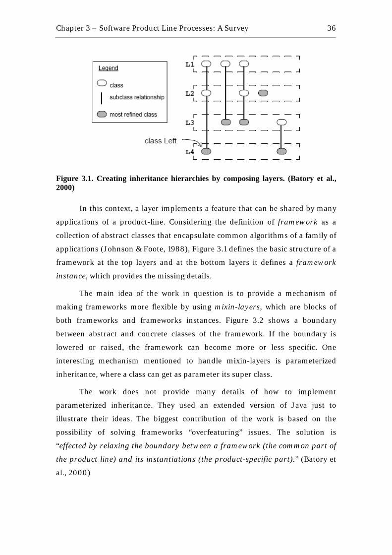
Chapter 3 – Software Product Line Processes: A Survey
36
Figure 3.1. Creating inheritance hierarchies by composing layers. (Batory et al., 2000)
In this context, a layer implements a feature that can be shared by many
applications of a product-line. Considering the definition of framework as a
collection of abstract classes that encapsulate common algorithms of a family of
applications (Johnson & Foote, 1988), Figure 3.1 defines the basic structure of a
framework at the top layers and at the bottom layers it defines a framework
instance, which provides the missing details.
The main idea of the work in question is to provide a mechanism of
making frameworks more flexible by using mixin-layers, which are blocks of
both frameworks and frameworks instances. Figure 3.2 shows a boundary
between abstract and concrete classes of the framework. If the boundary is
lowered or raised, the framework can become more or less specific. One
interesting mechanism mentioned to handle mixin-layers is parameterized
inheritance, where a class can get as parameter its super class.
The work does not provide many details of how to implement
parameterized inheritance. They used an extended version of Java just to
illustrate their ideas. The biggest contribution of the work is based on the
possibility of solving frameworks “overfeaturing” issues. The solution is
“effected by relaxing the boundary between a framework (the common part of
the product line) and its instantiations (the product-specific part).” (Batory et
al., 2000)
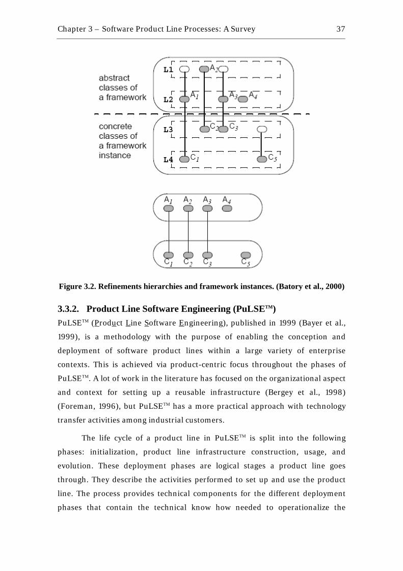
Chapter 3 – Software Product Line Processes: A Survey
37
Figure 3.2. Refinements hierarchies and framework instances. (Batory et al., 2000)
3.3.2. Product Line Software Engineering (PuLSETM) PuLSEΤΜ (Product Line Software Engineering), published in 1999 (Bayer et al.,
1999), is a methodology with the purpose of enabling the conception and
deployment of software product lines within a large variety of enterprise
contexts. This is achieved via product-centric focus throughout the phases of
PuLSEΤΜ. A lot of work in the literature has focused on the organizational aspect
and context for setting up a reusable infrastructure (Bergey et al., 1998)
(Foreman, 1996), but PuLSEΤΜ has a more practical approach with technology
transfer activities among industrial customers.
The life cycle of a product line in PuLSEΤΜ is split into the following
phases: initialization, product line infrastructure construction, usage, and
evolution. These deployment phases are logical stages a product line goes
through. They describe the activities performed to set up and use the product
line. The process provides technical components for the different deployment
phases that contain the technical know how needed to operationalize the

Chapter 3 – Software Product Line Processes: A Survey
38
product line development. In the initialization phase, the other phases and the
technical components are tailored. Through this tailoring of the technical
components, a customized version of the construction, usage, and evolution
phases of PuLSEΤΜ is created.
The technical components are: customizing (BC), scoping (Eco),
modeling (CDA), architecting (DSSA), instantiating (I), and evolving and
management (EM). Customization of PuLSEΤΜ to the context where it will be
applied ensures that the process and products are appropriate. Scoping
component has its focus on product definitions, being aware to not define a
product line with too many features. Modeling and architecting define the
domain-specific software architecture. Evolving and Management are
concerned with configuration management issues over the time and how to
integrate misfits in the line. Figure 3.3 shows the PuLSEΤΜ structure overview.
Figure 3.3. PuLSEΤΜ Overview (Bayer et al., 1999).

Chapter 3 – Software Product Line Processes: A Survey
39
As well as other product line processes, PuLSEΤΜ focus on a domain-
specific software architecture (DSSA), which can make possible the
development of new products just by changing or adding different features
considered by the variations points. The biggest problem is how to design this
architecture for different domains with appropriate details, as the lack of details
can make the whole process collapse. A possible solution can be to adopt a
specific Architecture Description Language (ADL), which is not the objective of
Bayer et al. They believe that the component PuLSEΤΜ - DSSA does not require
this kind of language, but it may not be true.
According to Atkinson et al. (Atkinson et al., 2000), PuLSEΤΜ has been
applied successfully in various contexts for different purposes. Among other
things, it has been helpful for introducing sound documentation and
development techniques into existing development practices. However, in
circumstances where there were no pre-existing processes or well-defined
products, the introduction of PuLSEΤΜ turned out to be problematic. In such
cases, the customization of PuLSEΤΜ was actually more concerned with the
introduction of basic software engineering processes than with the adaptation of
the product line ideas to existing processes.
3.3.3. Family-Oriented Abstraction, Specification and Translation (FAST) Still influenced by the Domain Engineering processes and based on industrial
experiences in software development, especially at Lucent Technologies and
Avaya Labs, David Weiss & Chi Lai presented the Family-Oriented Abstraction,
Specification and Translation (FAST) process (Weiss & Lai, 1999). Their goal is
to provide a systematic approach to analyze potential families and to develop
facilities and processes for generating family members. Because the process is
based on industrial experiences, mainly at Lucent Technologies, FAST defines
patterns for software production processes to balance the tradeoff between mass
production and careful and detailed engineering. FAST process is organized into
three sub-processes: Domain Qualification (DQ) – related to feasibility studies
of the family members, Domain Engineering – structuring reusable assets, and
Application Engineering – reusing the assets to generate new product family
members attending the customer requirements.

Chapter 3 – Software Product Line Processes: A Survey
40
As the process name says, FAST uses translation to transform the
application model into family members. The model is specified with an
Application Modeling Language (AML) and it is necessary to design a compiler
to read the model and generate the family members, which is not a trivial
activity.
3.3.4. The KobrA Approach In 2000, the Komponentenbasierte Anwendungsentwicklung (KobrA)
approach was published by Atkinson et al. (Atkinson et al., 2000). As it was said
in the last section, when there is no pre-existing software process, the
introduction of PuLSEΤΜ turned out to be problematic because basic software
engineering process principles would be the focus, instead of software reuse
principles. In this context, KobrA approach represents a synthesis of several
advanced software engineering technologies, including product lines,
component-based development, frameworks, and process modeling. It attempts
to create a natural synergy between the component-based and product line
approaches to software development (Atkinson et al., 2000). Atkinson et al.
mentioned: “From a product line perspective, KobrA represents an object-
oriented customization of the PuLSEΤΜ process”.
A fundamental tenet of KobrA is the strict distinction of products and
processes. The products of a KobrA project (e.g., models, documents, code
modules, test cases, etc.) are defined independently of, and prior to, the
processes by which they are created, and effectively represent the goals of these
processes. The transformation of an application into an executable form is
carried out in a distinct set of activities that are essentially orthogonal to the
framework and application engineering activities. The main purpose of the
framework engineering is “to create, and later maintain, a generic framework
that embodies all product variants that make up the family, including
information about their common and disjoint features” (Atkinson et al., 2000).
Besides, the main purpose of application engineering is “to instantiate this
framework to create particular variants in the product family, each tailored to
meet the specific needs of different customers, and later to maintain these
concrete variants” (Atkinson et al., 2000).
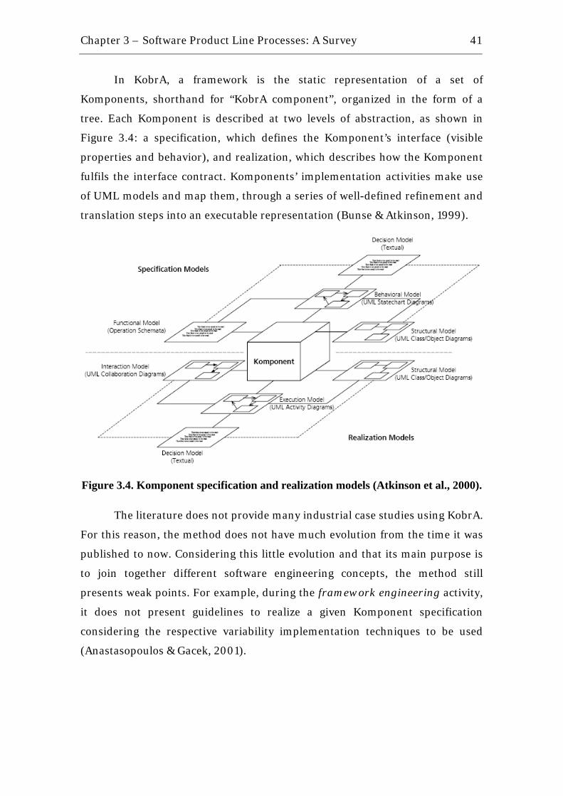
Chapter 3 – Software Product Line Processes: A Survey
41
In KobrA, a framework is the static representation of a set of
Komponents, shorthand for “KobrA component”, organized in the form of a
tree. Each Komponent is described at two levels of abstraction, as shown in
Figure 3.4: a specification, which defines the Komponent’s interface (visible
properties and behavior), and realization, which describes how the Komponent
fulfils the interface contract. Komponents’ implementation activities make use
of UML models and map them, through a series of well-defined refinement and
translation steps into an executable representation (Bunse & Atkinson, 1999).
Figure 3.4. Komponent specification and realization models (Atkinson et al., 2000).
The literature does not provide many industrial case studies using KobrA.
For this reason, the method does not have much evolution from the time it was
published to now. Considering this little evolution and that its main purpose is
to join together different software engineering concepts, the method still
presents weak points. For example, during the framework engineering activity,
it does not present guidelines to realize a given Komponent specification
considering the respective variability implementation techniques to be used
(Anastasopoulos & Gacek, 2001).
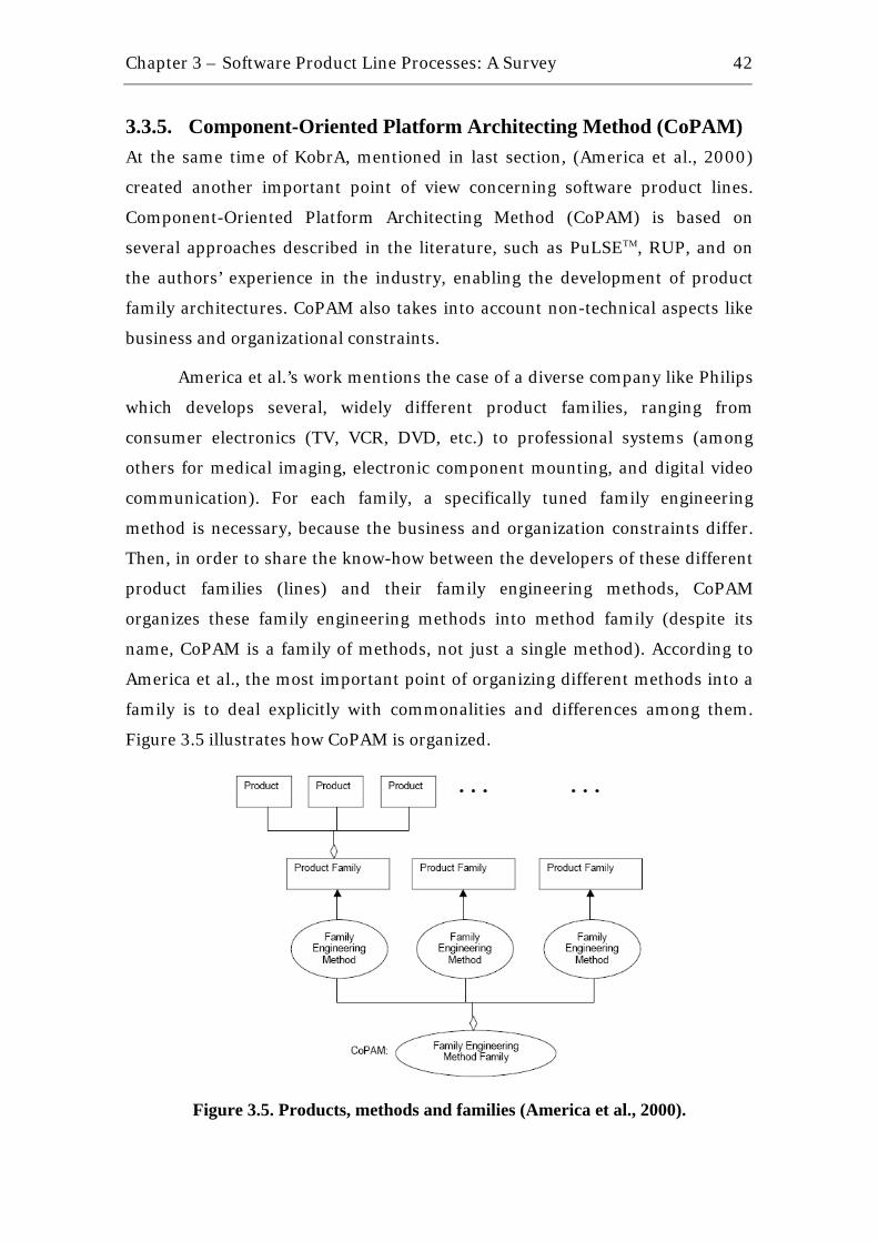
Chapter 3 – Software Product Line Processes: A Survey
42
3.3.5. Component-Oriented Platform Architecting Method (CoPAM) At the same time of KobrA, mentioned in last section, (America et al., 2000)
created another important point of view concerning software product lines.
Component-Oriented Platform Architecting Method (CoPAM) is based on
several approaches described in the literature, such as PuLSEΤΜ, RUP, and on
the authors’ experience in the industry, enabling the development of product
family architectures. CoPAM also takes into account non-technical aspects like
business and organizational constraints.
America et al.’s work mentions the case of a diverse company like Philips
which develops several, widely different product families, ranging from
consumer electronics (TV, VCR, DVD, etc.) to professional systems (among
others for medical imaging, electronic component mounting, and digital video
communication). For each family, a specifically tuned family engineering
method is necessary, because the business and organization constraints differ.
Then, in order to share the know-how between the developers of these different
product families (lines) and their family engineering methods, CoPAM
organizes these family engineering methods into method family (despite its
name, CoPAM is a family of methods, not just a single method). According to
America et al., the most important point of organizing different methods into a
family is to deal explicitly with commonalities and differences among them.
Figure 3.5 illustrates how CoPAM is organized.
Figure 3.5. Products, methods and families (America et al., 2000).
Chapter 3 – Software Product Line Processes: A Survey
43
It is important to mention why CoPAM was not organized into a larger
family or population instead of different product families (Ommering, 2000).
America et al. affirm that such a large population only makes sense if the
products in the family have enough in common to make it profitable and
manageable by the organization.
CoPAM is divided in three sub processes: platform engineering, product
engineering and family engineering. The first sub process develops a platform,
which consists of a number of reusable components. The product engineering
process develops products using these platform components, adding new
components where necessary. Both processes get input from and provide
feedback to the family engineering sub process. This last is different from the
other kinds of sub processes because it deals with family development.
As CoPAM main purpose is to organize a family of different product line
methods, it does not provide details on how to mount a specific product line and
also does not provide details on assets implementation. These details should be
recovered from each specific method that is being used for each specific product
line.
3.3.6. Software Product Lines by SEI In 2001, (Clements & Northrop, 2001) compiled several concepts of software
reuse and product lines, which are part of the Framework for Product Line
Practice, proposed by SEI. Clements & Northrop highlight management and
organizational issues concerning establishing a SPL processes, as (Czarnecki &
Eisenecker, 2000) mentioned to be necessary.
Clements & Northrop defend that product lines are based on three
essential activities: core asset development, product development and
management. The first activity goal is to establish a production capability for
products based on iterations. In this activity the product line scope is defined
with the existent constraints, styles, patterns and frameworks. Another output
of this activity, besides the scope, is the production plan used as input to
product development activity. This second activity consists basically in
transforming the reusable assets into real products. Supporting these two
activities, Management activity exists at both technical and organizational
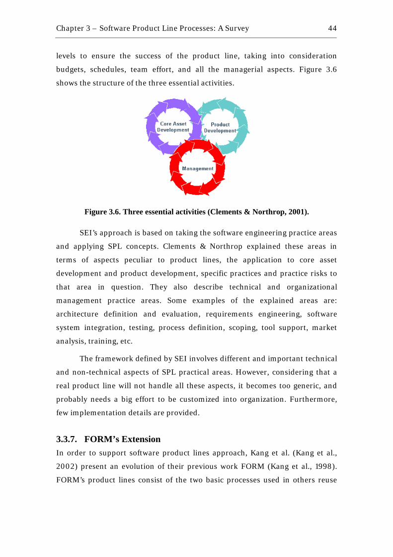
Chapter 3 – Software Product Line Processes: A Survey
44
levels to ensure the success of the product line, taking into consideration
budgets, schedules, team effort, and all the managerial aspects. Figure 3.6
shows the structure of the three essential activities.
Figure 3.6. Three essential activities (Clements & Northrop, 2001).
SEI’s approach is based on taking the software engineering practice areas
and applying SPL concepts. Clements & Northrop explained these areas in
terms of aspects peculiar to product lines, the application to core asset
development and product development, specific practices and practice risks to
that area in question. They also describe technical and organizational
management practice areas. Some examples of the explained areas are:
architecture definition and evaluation, requirements engineering, software
system integration, testing, process definition, scoping, tool support, market
analysis, training, etc.
The framework defined by SEI involves different and important technical
and non-technical aspects of SPL practical areas. However, considering that a
real product line will not handle all these aspects, it becomes too generic, and
probably needs a big effort to be customized into organization. Furthermore,
few implementation details are provided.
3.3.7. FORM’s Extension In order to support software product lines approach, Kang et al. (Kang et al.,
2002) present an evolution of their previous work FORM (Kang et al., 1998).
FORM’s product lines consist of the two basic processes used in others reuse

Chapter 3 – Software Product Line Processes: A Survey
45
process: Asset development, with the goal of producing reusable assets, and
Product Development, putting the assets together to develop new products.
The main difference of this extension compared to original FORM is the
concern in business aspects such as the Marketing and Product Plan (MPP).
The process still carries lack of details in conceptual architecture design,
architecture refinement and implementation activities.
3.3.8. Product Line UML-Based Software Engineering (PLUS) One of the most recent work in software product lines area was published by
(Gomaa, 2005). As the name mentions, PLUS adds the capabilities of UML-
based methods to software product lines. Gomaa affirms that the objective of
PLUS is to explicitly model the commonality and variability in a software
product line. The method provides a set of concepts, techniques and notations
to extend UML-based design methods and processes for single systems to
handle product line engineering. In addition, PLUS is compatible with the
iterative and incremental (spiral) method defined in Unified Software
Development Process (USDP) (Jacobson et al., 1999).
As UML capabilities are mapped in PLUS, the Requirements, Analysis
and Design Modeling are applied in the context of SPL. In Requirements
Modeling, Gomaa provides mechanisms to structure a use case model for a SPL
considering variability management and to document the use cases
appropriately. Feature modeling with UML is also provided.
In the Analysis Modeling phase, PLUS brings ways to perform static
modeling (basic structure of classes) of the SPL considering commonality and
variability. It also handles dynamic interaction modeling (sequence or
collaboration diagrams), finite state machines and state charts and feature/class
dependency modeling for SPL.
Finally, for the Design Modeling activity, software architecture patterns
(categorized in structure, communication and architectural) and component-
based software design are proposed. After the three steps mentioned are
performed, the SPL architecture is adapted and tailored to derive a given
software application.
Chapter 3 – Software Product Line Processes: A Survey
46
PLUS is an innovative method to software product lines based on UML.
Gomaa provides three different case studies to help applying the method in a
practical and industrial context. However, he does not provide many details on
component implementation and product line testing, which are not less
important than the three general steps mentioned.
3.3.9. Software Product Line Engineering (SPLE) Framework Also in 2005, in the same year of PLUS publication, the SPLE framework was
published (Pohl et al., 2005). Pohl et al. describe this framework as it
“incorporates the central concepts of traditional product line engineering,
namely the use of platforms and the ability to provide mass customization”.
They define a platform as a collection of reusable artifacts, in the software
context, and mass customization as the set of variabilities that can be applied to
different products in a product line.
The SPLE framework is divided in two phases: Domain Engineering,
responsible for establishing the reusable platform and thus for defining the
commonality and the variability of the product line; and Application
Engineering, is responsible for deriving product line applications from the
platform established in domain engineering. This differentiation between the
domain and application engineering processes is based on the proposal by
Weiss and Lai (Weiss & Lai, 1999). The entire framework is clearly exemplified
with a home automation case study.
The domain engineering process is composed of five key sub-processes:
product management, domain requirements engineering, domain design,
domain realization, and domain testing. In the same context, the application
engineering process is composed of the sub-processes application requirements
engineering, application design, application realization, and application testing.
Throughout the framework structure, Pohl et al. heavily explore the
concepts of variability in different contexts of the process and how to document
it in different types of artifacts, such as, requirements artifacts, design artifacts
and code (realization artifacts). The framework also brings clearly the
differences between product-line engineering and single-system engineering in
all the activities performed during the process’ phases.

Chapter 3 – Software Product Line Processes: A Survey
47
Specifically in domain realization phase, the framework approaches the
question of how to distribute variability over components and considers
different binding times for variability: before compilation, at compile time, at
link time, at load time and at run-time. For each mentioned time, well known
variability implementation techniques are cited, for example, aspect-oriented
programming, model-driven approaches, conditional compilation, among
others (Anastasopoulos & Gacek, 2001). Nevertheless, the framework still lacks
of guidelines for component realization and does not provide details on how to
apply those techniques in practice.
In addition, in the application realization phase, the framework affirms
that application-specific components are realized just as in single-system
engineering, emphasizing that, in many cases, domain interfaces can be reused
for application-specific components. In this case, an application-specific plug-in
component, for example, has to carry all interfaces that are determined by the
domain architecture for such a plug-in, and so the component’s internal
specification may become too complex.
3.4. Summary of the Study Based on the mentioned processes and methods, it was proposed the timeline of
research on software reuse processes area, presented in Figure 3.7 taking as
base the timeline described in (Almeida et al., 2005). The milestones are shown
in the Figure marked with an “X”. Observing this Figure, it can noticed that the
tendency to develop reuse processes based on software product line practices,
started from 1999, instead of domain engineering practices, which dated from
early 1980s.
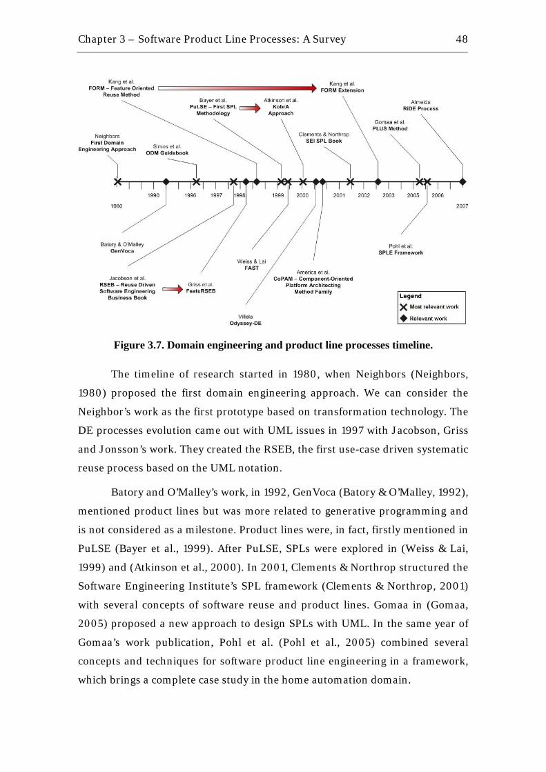
Chapter 3 – Software Product Line Processes: A Survey
48
Figure 3.7. Domain engineering and product line processes timeline.
The timeline of research started in 1980, when Neighbors (Neighbors,
1980) proposed the first domain engineering approach. We can consider the
Neighbor’s work as the first prototype based on transformation technology. The
DE processes evolution came out with UML issues in 1997 with Jacobson, Griss
and Jonsson’s work. They created the RSEB, the first use-case driven systematic
reuse process based on the UML notation.
Batory and O’Malley’s work, in 1992, GenVoca (Batory & O’Malley, 1992),
mentioned product lines but was more related to generative programming and
is not considered as a milestone. Product lines were, in fact, firstly mentioned in
PuLSE (Bayer et al., 1999). After PuLSE, SPLs were explored in (Weiss & Lai,
1999) and (Atkinson et al., 2000). In 2001, Clements & Northrop structured the
Software Engineering Institute’s SPL framework (Clements & Northrop, 2001)
with several concepts of software reuse and product lines. Gomaa in (Gomaa,
2005) proposed a new approach to design SPLs with UML. In the same year of
Gomaa’s work publication, Pohl et al. (Pohl et al., 2005) combined several
concepts and techniques for software product line engineering in a framework,
which brings a complete case study in the home automation domain.

Chapter 3 – Software Product Line Processes: A Survey
49
Taking all the mentioned SPL processes into consideration we can
conclude that:
• The processes commonly split a SPL into two distinct phases: core assets
development and application engineering. Clements & Northrop also
mention a third phase responsible for managing the creation and usage of
the core assets (Clements & Northrop, 2001). The first phase is
responsible for creating the reusable artifacts and the second reuses those
artifacts to create new applications in the domain being explored. The
core assets development phase is usually divided in three sub-phases:
domain analysis, which analyzes all the features of the domain; domain
modeling, which creates a reference architecture based on domain
features and models the components; and domain implementation,
which assembles the defined components.
• All of them present some lack of details on the domain implementation
phase. It means that they do not provide guidelines for implementing
components and for using the variability implementation techniques
during component realization steps. There is no sound example
documentation to aid the developer in the processes relating the
components with their respective variability implementation techniques
in use.
• Most of the processes present case studies, helping to introduce them in a
practical and industrial context. However, there are few case studies
showing some level of customization or adaptation of the processes
according to the reality of immature domains, such as, the mobile game
domain (Voget & Becker, 2002) in Java Micro Edition (JME) (Java ME,
2008), which carries restrictions that can make the application of a SPL
unfeasible. These restrictions are mainly related to the still unstable JME
platform and the big diversity of phones, bringing up many variation
points according to the phone manufacturer, for example, different
screen sizes, different API implementations and limited application size.
Chapter 3 – Software Product Line Processes: A Survey
50
3.5. Chapter Summary This chapter presented the main concepts about software reuse processes,
covering from component-based development, describing basic assumptions of
three different CBD processes, to software product lines, mentioning aspects of
domain engineering and focusing on core assets implementation phases. It was
presented nine relevant SPL processes from 1992 to 2007. At last, a timeline
was defined in order to summarize the main topic of this chapter.
Based on the issues described in this chapter about software reuse
processes, especially about SPL processes, the next chapter presents a practical
approach for implementing core assets in a SPL focusing on the mobile game
domain, since such domain is still little explored in case studies involving SPLs.
4 Core Assets Development in Software Product Lines - Towards a Practical Approach for the Mobile Game Domain
“If you can't explain it simply, you don't understand it well enough”
Albert Einstein (1879 – 1955) Nobel Prize in Physics (1921), German theoretical physicist
There are many cases of successful software product lines in practice (SPL Hall
of Fame, 2008), as it was mentioned in Chapter 2. Several domains have been
explored using the SPL approach, for example, consumer electronics
(Ommering et al., 2000), printing machines (Toft et al., 2000) and avionics,
including commercial jetliners and even spaceships (Sharp, 2000). However,
one specific domain in which there are few examples of SPLs is the mobile game
domain, mainly because the majority of the SPL processes listed in Chapter 3 do
not address appropriately the restrictions related to that specific domain,
especially in the domain implementation phase.
In this context, this chapter presents a practical approach for
implementing core assets in a software product line applied to the mobile game
domain and is organized as follows: Section 4.1 introduces the mobile game
domain and some specific characteristics of game development. In sequence,
Section 4.2 presents the proposal to core assets implementation in the mobile
game domain. Finally, Section 4.3 presents a summary of this chapter.

Chapter 4 – Core Assets Development in Software Product Lines - Towards a
Practical Approach for the Mobile Game Domain
52
4.1. Introduction It is common to hear from different sources in media1,2 that the game industry
outgrowth is overcoming the movie industry. In fact, the entertainment industry
has somehow shifted its attention to the games and this does not exclude mobile
games. But, despite what many people could think, mobile games do involve
some challenging aspects. For example, based on our industrial experience, a
typical mobile game can be hypothetically described like this: “our next project
will be an adventure game based on the Spiderman movie and must be
launched in three months from now, two weeks before the official movie
release. The game must run in 32 different phones from different
manufacturers, including Nokia, Motorola, Samsung, LG and Sony Ericsson
and must include 5 different languages: English, Portuguese, Spanish, French
and German. The game must use 3D capabilities and sound effects and the
final application size must not exceed 400 KB. The game must not take more
than 5 seconds during start up”. This small text exemplifies the problems and
restrictions of the mobile game domain, which can be summarized as:
• Short schedules: this problem is usually related to every software
project, but, especially in mobile game projects, there is a rush because
mobile games have a much smaller market window compared to other
projects given the strong competition. As soon they enter the market,
they tend to be quickly replaced by other titles.
• Big diversity of target handsets: the larger number of phones the
game can run, the bigger possibilities of download it has, and
consequently the bigger are the chances of success and profit for game
producers and operators. On the other hand, as the number of target
handsets grows, there is much more to be done to customize the
applications for all of them, because different variables must be taken
into consideration, for example: hardware restrictions – no camera,
no MP3 support, low storage capacity; processing power – it may
1 Microsoft targets blockbuster debut with 'Halo 3', available on: http://edition.cnn.com/2007/TECH/ 09/24/halo3.launch.ap/index.html, accessed in January, 2008. 2 DFC Intelligence forecasts video game market to reach $57 billion in 2009, available on http://www.dfcint.com/wp/?p=222, accessed in July, 2008.

Chapter 4 – Core Assets Development in Software Product Lines - Towards a
Practical Approach for the Mobile Game Domain
53
cause the phone to take too long to start an application; main memory
available – which can obligate the game producer to remove some
features; and application size – mobile phones have a maximum size
for applications, and the smaller the size is, the better for the customer to
reduce costs with download.
• Different API implementations: Java Micro Edition (JME) (Java
ME, 2008) is the most common platform for mobile phones and Sun
Microsystems is the main sponsor responsible for maintaining the
technology. Sun also sponsors the Java Community Process website3,
which gathers a group of experts in Java technology to standardize the
Java Specification Requests (JSRs). A mobile phone must implement a
minimum set of JSRs to be JME compatible and may extend this set with
any other features. This scenario leads some manufacturers to produce
proprietary implementation for some phone features. As an example, the
sound API is implemented differently in Samsung, Nokia and Motorola
phones. This is another side effect of the big diversity of target handsets.
The characteristics of this challenging scenario can be handled with
software product line engineering practices. The main aspect where a SPL could
help is related to the fact that mobile game producers usually implement many
different games but in the same domain. For example, adventure platform-
based side scrolling games. Applying a SPL process could help on performing
the domain analysis and structuring the reference architecture with its variation
points, but, in order to cover the restrictions of the domain mentioned, a SPL
process must provide as many details as possible in the domain implementation
phase. As we discussed in Chapter 3, the main references in the SPL processes
area lack of details in that phase, such as specific guidelines for variability
implementation and well defined inputs, outputs and roles. Moreover,
introducing SPL practices in the game domain requires adaptations, since the
classic software engineering techniques may not apply to that domain (Flynt &
Salem, 2005). There are different types of artifacts, activities, roles, inputs and
3 Java Community Process, available on http://jcp.org/en/home/index, accessed in May, 2008.
Chapter 4 – Core Assets Development in Software Product Lines - Towards a
Practical Approach for the Mobile Game Domain
54
outputs involved during game development (Rucker, 2002). For example, the
typical requirements elicitation and use case modeling phases are differently
performed for games given the dynamic environment where the user can take
distinct actions while playing. In most times, use cases for games can be
dispensed, or better, substituted by a game design document describing game
rules and behaviors (Rucker, 2002). In addition, there are efforts in the industry
to establish a software process tailored for the game development (Flood, 2003)
merging good practices from the well known software processes eXtreme
Programming (XP) (Beck, 1999) and Rational Unified Process (RUP)
(Jacobson et al., 1999).
Taking all those points into consideration, the purpose of this chapter is
to describe a practical approach for implementing core assets in a SPL applied
to the mobile game domain, providing as many details as possible to make the
domain implementation phase feasible.
4.2. Core Assets Development in Software Product Lines - Towards a Practical Approach for the Mobile Game Domain Based on the good practices from different domain engineering and SPL
processes described in Chapter 3, in conjunction with our industrial experience,
we structured an approach to cover the main aspects of the mobile game
domain, as shown in Figure 4.1.
The approach is focused on the domain implementation stage of a SPL,
abstracting the previous stages of domain analysis and design. The whole
process is iterative, although the Figure 4.1 does not show it clearly to avoid
complexity and misunderstandings.
In addition, the approach is divided in three phases: Component
Modeling (Section 4.2.1), Component Implementation (Section 4.2.2),
and Component Testing (Section 0).
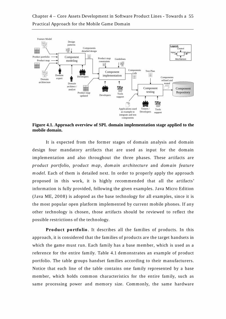
Chapter 4 – Core Assets Development in Software Product Lines - Towards a
Practical Approach for the Mobile Game Domain
55
Componentmodeling
Component implementation
Component testing
Feature Model
Components refined and
tested
Product map
Tools support
Domain architecture
DevelopersDomain expert
Testers /Developers
GuidelinesProduct map constraints
Product portfolio
Domain architect /
analyst
Tools supportDevelopers
Product map updated
ComponentRepository
Design patterns
Components detailed design
Applications used as example to
integrate and test components
Components code
Test Plan
Input Output
Control
Mechanism
Legend:
Figure 4.1. Approach overview of SPL domain implementation stage applied to the mobile domain.
It is expected from the former stages of domain analysis and domain
design four mandatory artifacts that are used as input for the domain
implementation and also throughout the three phases. These artifacts are
product portfolio, product map, domain architecture and domain feature
model. Each of them is detailed next. In order to properly apply the approach
proposed in this work, it is highly recommended that all the artifacts’
information is fully provided, following the given examples. Java Micro Edition
(Java ME, 2008) is adopted as the base technology for all examples, since it is
the most popular open platform implemented by current mobile phones. If any
other technology is chosen, those artifacts should be reviewed to reflect the
possible restrictions of the technology.
Product portfolio. It describes all the families of products. In this
approach, it is considered that the families of products are the target handsets in
which the game must run. Each family has a base member, which is used as a
reference for the entire family. Table 4.1 demonstrates an example of product
portfolio. The table groups handset families according to their manufacturers.
Notice that each line of the table contains one family represented by a base
member, which holds common characteristics for the entire family, such as
same processing power and memory size. Commonly, the same hardware

Chapter 4 – Core Assets Development in Software Product Lines - Towards a
Practical Approach for the Mobile Game Domain
56
platform is used for all handsets in a family. The domain restrictions are
detailed in each line of the table in terms of, screen size (column “SCREEN”),
heap memory size (column “HEAP”) and application maximum size (column
“JAR”). All other information, such as MIDP version and comments about the
family, can further help in component modeling phase, specifically in the
component internal design. At the bottom of the table, a list is provided with the
priorities among the families of handsets, helping to decide which product
should be released first. This list is structured based on market needs and
specific project purposes. For example, the “NOKIA_1” family gets the first
priority amongst Nokia phones because it has a very restricted hardware
platform and, once an application is developed for it, it would be easier to port
the same application for other families that are not so restricted.
Table 4.1. Example of product portfolio with priorities among families of handsets.
Manufacturer #1: Motorola FAMILY BASE COMPATIBILITY SCREEN MIDP HEAP JAR MP3 COMMENTS
MOTO_1 i830 i830; i265; i275; i560 130x130 2.0 1.1 Mb 4 Mb Too low fps rate for 3D games
MOTO_2 i850 i850; i870; i880 176x206 2.0 4 Mb 4 Mb Phonebook access is made using PIM API
Manufacturer #2: Nokia FAMILY BASE COMPATIBILITY SCREEN MIDP HEAP JAR MP3 COMMENTS
NOKIA_1 3100 2355; 2650; 3100 128x128 1.0 200 kb 64 kb
NOKIA_2 3220 2600; 2610; 3220; 6020; 6021; 6030; 6230 128x128 2.0 512 kb 128 kb
Being shipped in Korea. Applications must include Korean language.
Manufacturer #3: Sony Ericsson
FAMILY BASE COMPATIBILITY SCREEN MIDP HEAP JAR MP3 COMMENTS
SE_1 P900 P800; P802; P900; P908; P910; 208x320 1.0 512 kb 1 Mb
SE_2 T618 T610; T616; T618 128x127 1.0 256 kb 100 kb Handsets not recommended for 3D applications
PRIORITY MEMBER BASE COMMENTS
1 MOTO_2 i850 This family of handsets was very well sold in Europe and USA
2 MOTO_1 i830 Low end phones. Target: Nextel Brazil next trimester
3 NOKIA_1 3100 First priority amongst Nokia handsets
4 NOKIA_2 3220
5 SE_2 T618 First consult the client to verify the availability of handsets for tests
6 SE_1 P900 Reduced market for this handset family makes the priority low
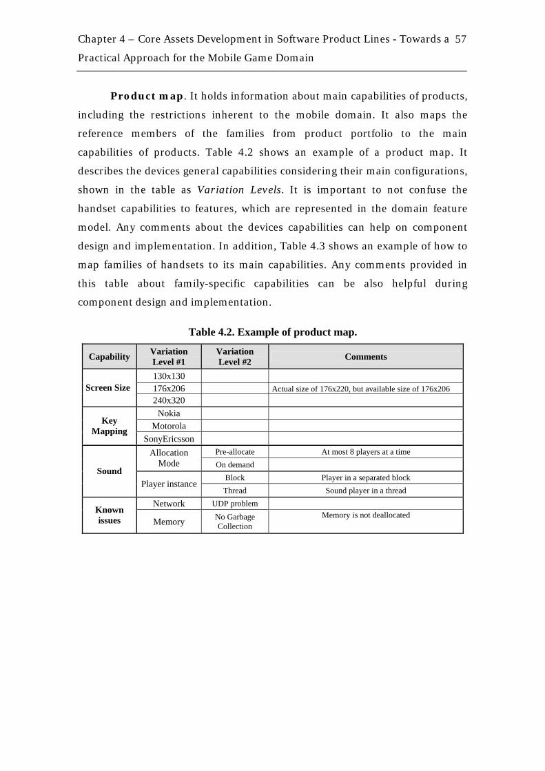
Chapter 4 – Core Assets Development in Software Product Lines - Towards a
Practical Approach for the Mobile Game Domain
57
Product map. It holds information about main capabilities of products,
including the restrictions inherent to the mobile domain. It also maps the
reference members of the families from product portfolio to the main
capabilities of products. Table 4.2 shows an example of a product map. It
describes the devices general capabilities considering their main configurations,
shown in the table as Variation Levels. It is important to not confuse the
handset capabilities to features, which are represented in the domain feature
model. Any comments about the devices capabilities can help on component
design and implementation. In addition, Table 4.3 shows an example of how to
map families of handsets to its main capabilities. Any comments provided in
this table about family-specific capabilities can be also helpful during
component design and implementation.
Table 4.2. Example of product map.
Capability Variation Level #1
Variation Level #2 Comments
130x130 176x206 Actual size of 176x220, but available size of 176x206 Screen Size 240x320
Nokia Motorola
Key Mapping
SonyEricsson Pre-allocate At most 8 players at a time Allocation
Mode On demand Block Player in a separated block
Sound Player instance
Thread Sound player in a thread Network UDP problem
Known issues Memory No Garbage
Collection Memory is not deallocated
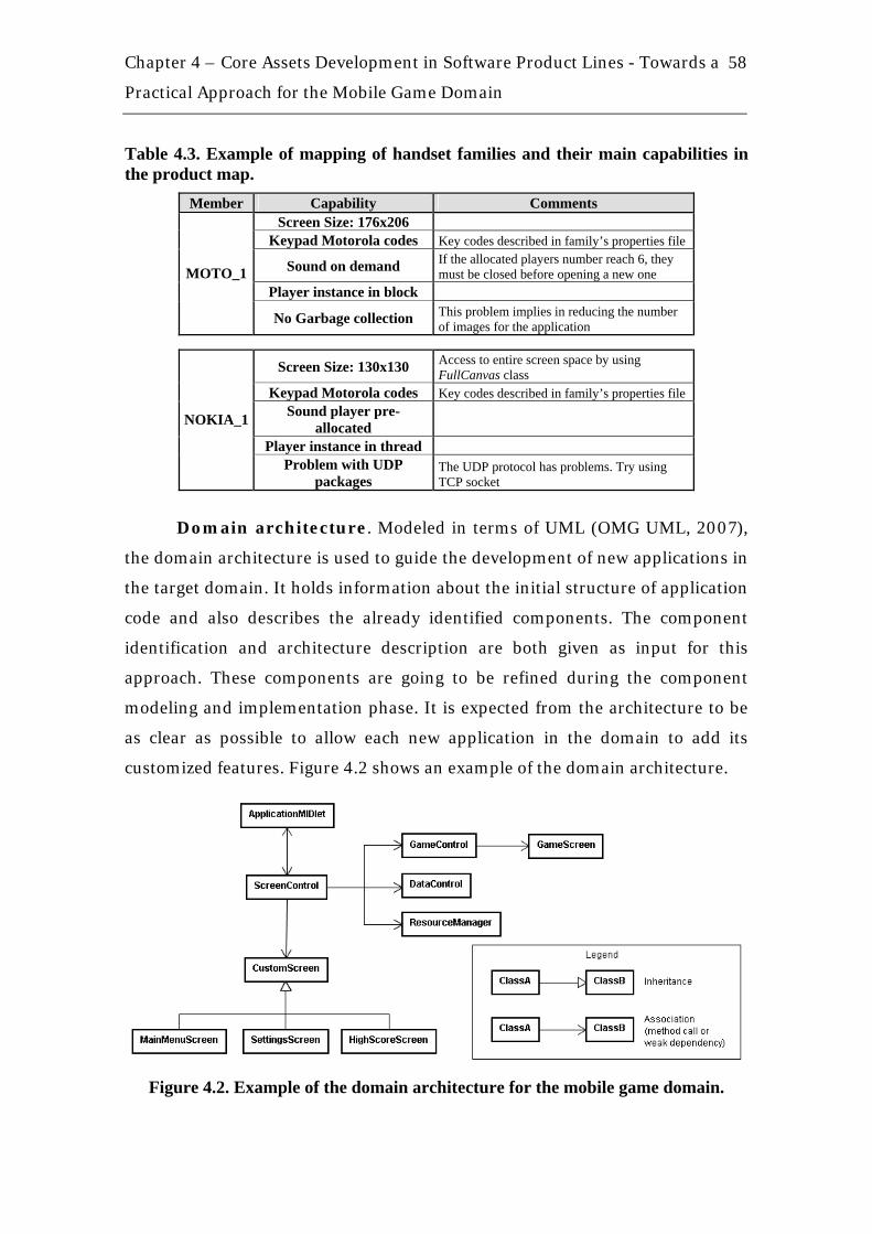
Chapter 4 – Core Assets Development in Software Product Lines - Towards a
Practical Approach for the Mobile Game Domain
58
Table 4.3. Example of mapping of handset families and their main capabilities in the product map.
Member Capability Comments Screen Size: 176x206
Keypad Motorola codes Key codes described in family’s properties file
Sound on demand If the allocated players number reach 6, they must be closed before opening a new one
Player instance in block MOTO_1
No Garbage collection This problem implies in reducing the number of images for the application
Screen Size: 130x130 Access to entire screen space by using FullCanvas class
Keypad Motorola codes Key codes described in family’s properties file Sound player pre-
allocated Player instance in thread
NOKIA_1
Problem with UDP packages
The UDP protocol has problems. Try using TCP socket
Domain architecture. Modeled in terms of UML (OMG UML, 2007),
the domain architecture is used to guide the development of new applications in
the target domain. It holds information about the initial structure of application
code and also describes the already identified components. The component
identification and architecture description are both given as input for this
approach. These components are going to be refined during the component
modeling and implementation phase. It is expected from the architecture to be
as clear as possible to allow each new application in the domain to add its
customized features. Figure 4.2 shows an example of the domain architecture.
Figure 4.2. Example of the domain architecture for the mobile game domain.

Chapter 4 – Core Assets Development in Software Product Lines - Towards a
Practical Approach for the Mobile Game Domain
59
Domain feature model. Described in terms of visual models following
well accepted notation, such as FODA (Kang et al., 1990), this artifact shows the
relationships among domain features. The domain feature model can be used to
guide while refining product portfolio and product map throughout the
approach.
Also observing Figure 4.1, we can find five different roles:
• Domain expert: person who knows the details about the domain being
explored. Usually, this person had already developed many different
projects in the domain.
• Domain analyst: responsible for analyzing domain features and possibly
refining product portfolio and product map. In general, the domain
analyst is also the domain expert.
• Domain architect: responsible for modeling components’ internal design
and choosing which variability mechanism is most appropriate for each
component to be developed.
• Developer: person who actually implements components in the target
technology, in this case JME, based on components’ internal design.
• Tester: responsible for testing each implemented component separately
and further the product resulting from the component integration and
architecture instantiation.
4.2.1. Component Modeling The main goal of this phase is to obtain the component detailed design (or
component specification). For this purpose, the domain architect is the most
important role, responsible for analyzing the architecture and modeling the
already identified components. This work does not focus on component
identification, but it can be observed as an important research field as described
in (Almeida, 2007b), which considers the functional dependency among use
cases. Another important research field handles with automatic component
composition (White et al., 2008). As the average size of mobile games, in terms

Chapter 4 – Core Assets Development in Software Product Lines - Towards a
Practical Approach for the Mobile Game Domain
60
of lines of code, tends to be smaller than other projects (Alves et al., 2005b),
such as desktop or console games, the components are easier to identify and the
architecture is not much complex. Thus, component identification and
composition activities can be performed only based on architect experience.
During component modeling, the architect must take into consideration
all information described in product portfolio and product map, because these
artifacts may bring up some restrictions that must be addressed in components’
internal design, such as, a family of handsets which have reduced memory size.
Furthermore, the domain feature model can be used to identify component
dependencies between each other. In order to reduce final component
complexity and increase maintainability, design patterns must be considered
(Gamma et al., 1995).
Before defining the internal component structure, the domain architect
must decide which implementation technique will be used to handle the
variation levels (or variation points) in product map (example in Table 4.2). One
of the most common implementation techniques applied to mobile domain is
conditional compilation (Alves et al., 2006). This technique can be easily
applied to cut off unnecessary code and reduce the final application size.
Although conditional compilation tags can reduce the code readability, there are
tools to perform refactoring steps (Alves et al., 2005b) helping the code to
remain readable. The use of conditional compilation tags does not exclude the
use of any other variability implementation technique, such as, inheritance,
delegation or aspect-oriented programming (AOP).
In order to add the conditional compilation tags for each respective
variation level, the example product map, shown in Table 4.2, and also the
mapping of handset families and their main capabilities, shown in Table 4.3, are
refined. The results are shown in Table 4.4 and Table 4.5, respectively. The
information in Table 4.5 can be used to automatically deploy new products from
product line.

Chapter 4 – Core Assets Development in Software Product Lines - Towards a
Practical Approach for the Mobile Game Domain
61
Table 4.4. Example of product map with conditional compilation tags attached.
Capability Variation Level #1
Variation Level #2
Conditional Compilation Tag Comments
130x130 screen_130x130
176x206
screen_176x206 Actual size of 176x220, but available size of 176x206
Screen Size
240x320 screen_240x320 Nokia keys_nokia
Motorola keys_motorola Key
Mapping SonyEricsson keys_sonyericsson
Pre-allocate sound_mode_prealloc At most 8 players at a timeAllocation Mode On demand sound_mode_ondemand
Block sound_player_block Player in a separated blockSound
Player instance Thread sound_player_thread Sound player in a thread
Network UDP problem known_issue_network Known issues Memory No Garbage
Collection known_issue_memory Memory is not deallocated
Table 4.5. Example of mapping of handset families, their main capabilities and the respective conditional compilation tags.
Member Capability Conditional Compilation Tag Comments
Screen Size: 176x206 screen_176x206
Keypad Motorola codes keys_motorola Key codes described in family’s properties file
Sound on demand sound_mode_ondemand If the allocated players number reach 6, they must be closed before opening a new one
Player instance in block sound_player_block
MOTO_1
No Garbage collection known_issue_memory This problem implies in reducing the number of images for the application
Screen Size: 130x130 screen_130x130 Access to entire screen space by using FullCanvas class
Keypad Motorola codes keys_motorola Key codes described in family’s properties file
Sound player pre-allocated sound_mode_prealloc
Player instance in thread sound_player_thread
NOKIA_1
Problem with UDP packages known_issue_network The UDP protocol has problems.
Try using TCP socket.
To start performing the component specification, the KobrA approach
(Atkinson et al., 2000) is used as a reference and adapted. KobrA approach was
chosen to be adapted because it describes a component using two levels of
abstraction (internal and external point of views) and this makes it easier for

Chapter 4 – Core Assets Development in Software Product Lines - Towards a
Practical Approach for the Mobile Game Domain
62
developers and component users (integrators) to understand the component
behavior. A KobrA component (called as Komponent to abbreviate) is based on
specification and realization models. Both models are composed by a general set
of UML models: specification – functional model, behavioral model, structural
model and decision model; realization – interaction model, execution model,
structural model and decision model (more detailed description of KobrA
approach is provided in Chapter 3).
In this approach, it is discouraged the use of textual models, such as the
decision model, and suggested only the use of a structural model. Doing it this
way may avoid misunderstandings problems with textual representations and
maintenance problems, if the textual model has to reflect the big number of
handset families. On the other hand, it is encouraged the use of the structural
model, which is the base for component implementation, combined with
<<variant>> stereotype to indicate a variant part of the component internal
design, as shown in Figure 4.3. The domain feature model is used to help on
identifying where the <<variant>> stereotype should be applied. Product
portfolio and product map help while designing components to make them
complaint to the game domain restrictions.
Figure 4.3. Example of internal component design (structural model) with the use of variant stereotype.
Moreover, the components can contain any of the conditional
compilation tags listed in product map. In this situation, the component
internal design should be complemented with additional information that refers

Chapter 4 – Core Assets Development in Software Product Lines - Towards a
Practical Approach for the Mobile Game Domain
63
to which tags are being used by any specific component, as Figure 4.4 shows. It
is perfectly acceptable that not all of the tags are known at the time the
component is being designed. Usually, the tags firstly identified are the ones
directly related to product map restrictions. After actually implementing the
component, its internal design information should be updated to reflect the last
version of code.
Figure 4.4. Example of component internal design with additional information of the applicable conditional compilation tags.
In order to detail any information about the handset families and their
restrictions, the domain expert may be consulted. Developers may also help on
specifying components and their interfaces, if exist.
4.2.2. Component Implementation Once the components’ internal design has been accomplished, the developers
are responsible for implementing these components using information from
components’ internal design (structural models), product portfolio descriptions,
product map constraints and domain feature model.
As the developers have participated in the Component Modeling phase,
they are supposed to be familiarized with internal component design and so can
initiate components implementation. The major concern at this point is to code
the domain restrictions and variability within the components specified using
the already known techniques for variability implementation in product lines
(Anastasopoulos & Gacek, 2001). These techniques are: conditional
compilation, aggregation / delegation, inheritance, dynamic class loading,
Chapter 4 – Core Assets Development in Software Product Lines - Towards a
Practical Approach for the Mobile Game Domain
64
properties, parameterization, overloading, design patterns, function libraries
(utility classes), aspect-oriented programming (AOP), reflection and dynamic
link libraries (DLLs). Among these techniques, only two of them, reflection and
dynamic link libraries (DLLs), are not applicable to mobile domain because the
current versions of MIDP/CLDC 2.1/1.14 respectively, still do not support them.
In the sequence, for each applicable technique mentioned, guidelines and
good practices of programming are presented through example scenarios to
help developers during component implementation.
Conditional Compilation. It enables control over the code segments
to be included or excluded from a program compilation defined by pre
processing symbols. This technique is largely used in the mobile domain, mainly
because it takes out of the application scope all unnecessary code, leaving the
application as compact as possible to be deployed to different handsets with
completely different capabilities. The major weak point of this technique is
related to maintenance, since the code may become hard to read and also not be
compilable in some environments. To mitigate this issue, support tools can be
used to manage conditional compilation tags and then make it easier to build
applications in the environment they are being deployed. Conditional
compilation can become a powerful technique to be used when correctly
combined with others techniques and good programming practices. Throughout
the description of the other variability implementation techniques next,
conditional compilation will be also explored, showing how to combine this
technique with the others.
Example Scenario for Conditional Compilation. One common situation
where conditional compilation can be used is when it is needed to add an
optional feature to a specific product in the product line without increasing the
other products size. For example, if one specific customer needs to add its logo
on the first screen of the game, usually called “splash” screen. The code
responsible to instantiate the logo image and paint it on screen should be
4 The Mobile Information Device Profile (MIDP), when combined with the Connected Limited Device Configuration (CLDC), is the Java runtime environment for today's most popular compact mobile information devices, such as cell phones and mainstream PDAs.

Chapter 4 – Core Assets Development in Software Product Lines - Towards a
Practical Approach for the Mobile Game Domain
65
embraced by conditional compilation tags, as shown in the following code
snippet. Doing it this way, will not cause the other products to have its final size
increased.
public class SplashScreen extends Canvas { protected void paint(Graphics g) { // ... Default painting
//#ifdef logo_x_customer g.drawImage(ImageResource.getInstance().getCustomerXLogo(), 0, 0, Graphics.TOP | Graphics.LEFT); //#endif
// ... } } class ImageResource { // ... Singleton instantiation
//#ifdef logo_x_customer private Image customerXLogo; public Image getCustomerXLogo() { if (this.customerXLogo == null) { try { this.customerXLogo= Image.createImage("/customer_x_logo.png"); } catch (IOException e) { e.printStackTrace(); } } return this.customerXLogo; } //#endif
}
Aggregation/Delegation. Aggregation is an object oriented technique
which enables objects to virtually support any functionality by forwarding
requests they can normally not satisfy to so-called delegation objects which
provide the requested services. Delegation is explored by different design
patterns, but it is common to see Delegation with used with facade pattern.
Example Scenario for Aggregation/Delegation. This technique is usually
necessary when a given object has different functionalities and needs to delegate
some services to another object. For example, if it is needed to isolate the sound

Chapter 4 – Core Assets Development in Software Product Lines - Towards a
Practical Approach for the Mobile Game Domain
66
component and delegate specific functionality to a sound controller and a player
controller. The suggested approach to use Aggregation/Delegation is to combine
it with conditional compilation tags and isolate these tags in delegated object,
embracing its whole method bodies. Try to maintain the tags only inside these
methods. Other methods that call the delegated one must not be embraced by
the tags to avoid spreading tags all over the code. The following code snippet
represents delegation technique combined with conditional compilation tags.
public class SoundFacade { public void playSnd(String filename) { // No tags in here SoundCtrl.playSnd(filename); } public void preallocatePlayers(int initialNumberOfPlayers) { // No tags in here PlayerCtrl.preallocatePlayers(initialNumberOfPlayers); } } class SoundCtrl { static void playSnd(String filename) {
// Entire delegated method body embraced by tags //#ifdef sound_player_block //sound code 1 //#elif sound_player_thread //sound code 2 //#endif
} } class PlayerCtrl { static void preallocatePlayers(int initialNumberOfPlayers) {
// Entire delegated method body embraced by tags //#ifdef sound_mode_prealloc //sound code 1 //#endif
} }
Inheritance. It is used to assign basic functionality to super classes and
extensions to subclasses. Inheritance should be used carefully in mobile domain
because the basic functionality present on super classes has to be really

Chapter 4 – Core Assets Development in Software Product Lines - Towards a
Practical Approach for the Mobile Game Domain
67
applicable for all subclasses to avoid unused methods and consequent increase
of the final application size.
Example Scenario for Inheritance. Consider a game where projectiles are
shot in the direction of the player and they can make a straight or curve path,
according to the handset screen size in which the game will run. An abstract
super class Projetctile and two subclasses, FireBall and Missile, are defined. In
this typical situation, it is recommended that the entire subclasses’ bodies are
embraced by conditional compilation tags according to the target handset
screen size. The following code snippet represents inheritance technique
combined with conditional compilation tags.
class Player { private int lifePercentage = 100; public void damage(int damagePercentage) { this.lifePercentage = this.lifePercentage - damagePercentage; } } public abstract class Projectile { public abstract void followPlayerAndDamage (Player player); }
//#ifdef screen_130x130 class FireBall extends Projectile { public void followPlayerAndDamage(Player player) { // Code to follow player in a straight line path player.damage(15); } } //#endif
//#ifdef screen_176x206 class Missile extends Projectile { public void followPlayerAndDamage(Player player) { // Code to follow player in a curve path player.damage(25); } } //#endif
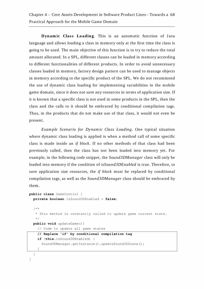
Chapter 4 – Core Assets Development in Software Product Lines - Towards a
Practical Approach for the Mobile Game Domain
68
Dynamic Class Loading. This is an automatic function of Java
language and allows loading a class in memory only at the first time the class is
going to be used. The main objective of this function is to try to reduce the total
amount allocated. In a SPL, different classes can be loaded in memory according
to different functionalities of different products. In order to avoid unnecessary
classes loaded in memory, factory design pattern can be used to manage objects
in memory according to the specific product of the SPL. We do not recommend
the use of dynamic class loading for implementing variabilities in the mobile
game domain, since it does not save any resources in terms of application size. If
it is known that a specific class is not used in some products in the SPL, then the
class and the calls to it should be embraced by conditional compilation tags.
Thus, in the products that do not make use of that class, it would not even be
present.
Example Scenario for Dynamic Class Loading. One typical situation
where dynamic class loading is applied is when a method call of some specific
class is made inside an if block. If no other methods of that class had been
previously called, then the class has not been loaded into memory yet. For
example, in the following code snippet, the Sound3DManager class will only be
loaded into memory if the condition of isSound3DEnabled is true. Therefore, to
save application size resources, the if block must be replaced by conditional
compilation tags, as well as the Sound3DManager class should be embraced by
them.
public class GameControl { private boolean isSound3DEnabled = false; /** * This method is constantly called to update game current state. */ public void updateGame(){ // Code to update all game states
// Replace 'if' by conditional compilation tag if (this.isSound3DEnabled) { Sound3DManager.getInstance().updateSound3DScene(); }
} }

Chapter 4 – Core Assets Development in Software Product Lines - Towards a
Practical Approach for the Mobile Game Domain
69
// Embrace entire class with conditional compilation tags class Sound3DManager { public static Sound3DManager getInstance() { return INSTANCE; // Singleton instance } public void updateSound3DScene() { // Code to update sound 3D scene } }
Properties. Properties files can be used as a powerful technique to
group all characteristics of a given device. For example, the set of conditional
compilation tags, the name of resources folder, the set of all handsets in that
specific family, all these information can be in a property file to be read during
application deployment or even at runtime to execute certain functions.
Example Scenario for Properties. A common example of use of
properties file is when the mobile application needs to be translated to different
languages. All application texts are stored in a properties file, each text
identified by an ID. For each different language needed, a different properties
file is created. At compilation time, a build script selects from different
properties files and creates the application archive (JAR file). It means that, for
each different language, there will be a different JAR file. The following code
snippet shows the basic structure of a properties file.
Properties-en-us.txt SPLASH_TEXT = Welcome to this wonderful game MENU_NEW_GAME = New Game MENU_SETTINGS = Settings MENU_EXIT = Exit Game QUESTION_EXIT = Are you sure you want to exit the game?
Properties-pt-br.txt SPLASH_TEXT = Bem-vindo a este jogo maravilhoso MENU_NEW_GAME = Novo Jogo MENU_SETTINGS = Configurações MENU_EXIT = Sair do Jogo QUESTION_EXIT = Você tem certeza que deseja sair do jogo?
Parameterization. The behavior of the method being called is
determined by the values of the parameters that are being set. Parameterization
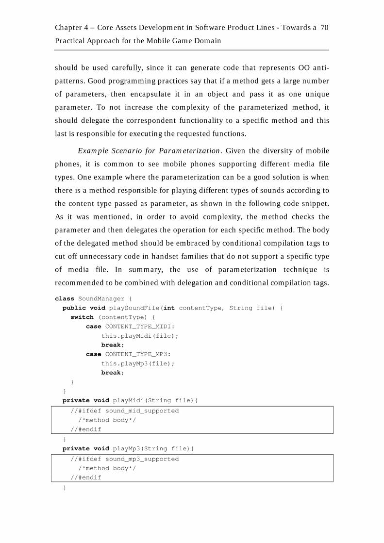
Chapter 4 – Core Assets Development in Software Product Lines - Towards a
Practical Approach for the Mobile Game Domain
70
should be used carefully, since it can generate code that represents OO anti-
patterns. Good programming practices say that if a method gets a large number
of parameters, then encapsulate it in an object and pass it as one unique
parameter. To not increase the complexity of the parameterized method, it
should delegate the correspondent functionality to a specific method and this
last is responsible for executing the requested functions.
Example Scenario for Parameterization. Given the diversity of mobile
phones, it is common to see mobile phones supporting different media file
types. One example where the parameterization can be a good solution is when
there is a method responsible for playing different types of sounds according to
the content type passed as parameter, as shown in the following code snippet.
As it was mentioned, in order to avoid complexity, the method checks the
parameter and then delegates the operation for each specific method. The body
of the delegated method should be embraced by conditional compilation tags to
cut off unnecessary code in handset families that do not support a specific type
of media file. In summary, the use of parameterization technique is
recommended to be combined with delegation and conditional compilation tags.
class SoundManager { public void playSoundFile(int contentType, String file) { switch (contentType) { case CONTENT_TYPE_MIDI: this.playMidi(file); break; case CONTENT_TYPE_MP3: this.playMp3(file); break; } } private void playMidi(String file){
//#ifdef sound_mid_supported /*method body*/ //#endif
} private void playMp3(String file){
//#ifdef sound_mp3_supported /*method body*/ //#endif
}
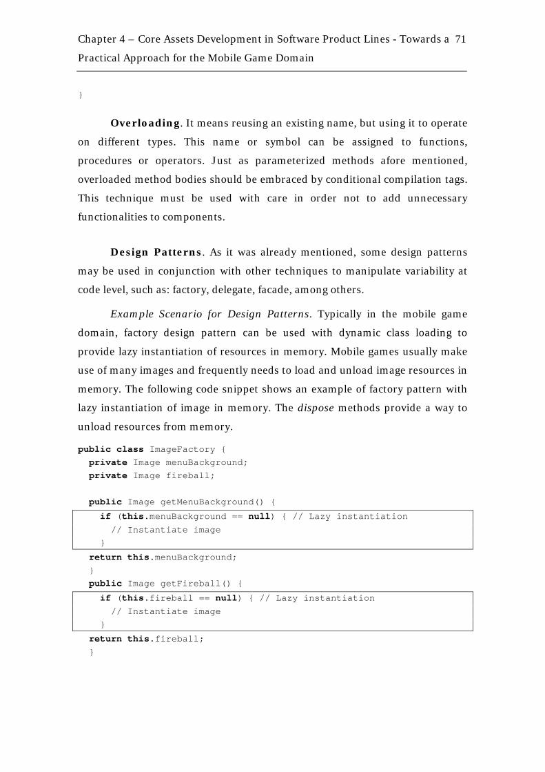
Chapter 4 – Core Assets Development in Software Product Lines - Towards a
Practical Approach for the Mobile Game Domain
71
}
Overloading. It means reusing an existing name, but using it to operate
on different types. This name or symbol can be assigned to functions,
procedures or operators. Just as parameterized methods afore mentioned,
overloaded method bodies should be embraced by conditional compilation tags.
This technique must be used with care in order not to add unnecessary
functionalities to components.
Design Patterns. As it was already mentioned, some design patterns
may be used in conjunction with other techniques to manipulate variability at
code level, such as: factory, delegate, facade, among others.
Example Scenario for Design Patterns. Typically in the mobile game
domain, factory design pattern can be used with dynamic class loading to
provide lazy instantiation of resources in memory. Mobile games usually make
use of many images and frequently needs to load and unload image resources in
memory. The following code snippet shows an example of factory pattern with
lazy instantiation of image in memory. The dispose methods provide a way to
unload resources from memory.
public class ImageFactory { private Image menuBackground; private Image fireball; public Image getMenuBackground() {
if (this.menuBackground == null) { // Lazy instantiation // Instantiate image }
return this.menuBackground; } public Image getFireball() {
if (this.fireball == null) { // Lazy instantiation // Instantiate image }
return this.fireball; }

Chapter 4 – Core Assets Development in Software Product Lines - Towards a
Practical Approach for the Mobile Game Domain
72
private void disposeInGameImages() { this.fireball = null; } private void disposeMenuImages() { this.menuBackground = null; } }
Function Libraries (Utility Classes). One of the most powerful ways
to apply software reuse is to maintain a library of methods/functions and/or
components, just as in (McIlroy, 1968). The library can contain mathematical
functions, network connections manager components, image processing
functions, among others. It can be properly applied to the mobile domain
context without restrictions. As it is possible that some products in the product
line do not use some of the methods, a suggestion for reusing such a library in
mobile domain is applying a tool to cut unused methods off the library during
the deployment process. An obfuscator tool, such as ProGuard5, usually
performs this operation as a side effect of the obfuscation process.
Example Scenario for Function Libraries (Utility Classes). Mounting a
function/method library in the mobile game domain is usually necessary when
the required functionalities are not present in the native API, for example,
Calendar class to manipulate dates or complementary String and Image
manipulation. This last example is shown in the following code snippet. Notice
that all methods are public and static and must be well documented to ease their
future reuse.
5 ProGuard is a free Java class file shrinker, optimizer, obfuscator, and preverifier. It detects and removes unused classes, fields, methods, and attributes. It optimizes bytecode and removes unused instructions. Available on http://proguard.sourceforge.net/, accessed in November, 2007.

Chapter 4 – Core Assets Development in Software Product Lines - Towards a
Practical Approach for the Mobile Game Domain
73
public class StringUtil { /** * Wraps text in lines that fit the screen. * * @param s String to be wrapped. * @param font Font used to draw the String. * @param maxLineSize Maximum number of horizontal pixels to draw * the given text. * @return A String array where each position is a screen line * of text. */ public static String[] wrapText(String s, Font font, int maxLineSize) { /* Method body */ } } public class ImageUtil { // Different package from StringUtil class /** * Creates an image in Gray Scale mode from the original image given * as parameter. * * @param original An image to be converted. * @return Image The desired image in a Gray Scale mode. */ public static Image toGrayScale(Image original) {/* Method body */} }
Aspect-Oriented Programming (AOP). As it was already mentioned,
mobile games must adhere to strong portability requirements. Service carriers
typically demand that a single application be deployed in a dozen or more
platforms. Each platform generally has different kinds of variation, such as,
vendor-specific APIs and memory and display constraints. These specific kinds
of variation may sometimes be considerably fine-grained such that they
generally crosscut the game core and are tangled with other kinds of variation.
Aspect-Oriented languages support the modular definition of concerns that are
generally spread throughout the system and tangled with core features. These
are called crosscutting concerns and their separation promotes the construction
of a modular system, avoiding code tangling and scattering.
AspectJ (AspectJ, 2008) is the most widely used aspect-oriented
extension to Java. Programming with AspectJ involves both aspects and classes
to separate concerns. Concepts which are well defined with object-oriented

Chapter 4 – Core Assets Development in Software Product Lines - Towards a
Practical Approach for the Mobile Game Domain
74
constructs are implemented in classes. Crosscutting concerns are usually
separated using units called aspects, which are integrated with classes through a
process called weaving. Thus, an AspectJ application is composed of both
classes and aspects. Therefore, each AspectJ aspect defines a functionality that
affects different parts of the system. Aspects may define pointcuts, advice and
inter-type declarations. Pointcuts describe join points, which are sets of points
of the program execution flow. Code to be executed at join points is declared as
advice. Inter-type declarations are structures that allow the introduction of
fields and methods into a class.
Applying AOP to mobile product lines can be an interesting approach to
reduce development efforts while porting mobile applications (Alves et al.,
2006). In an attempt to adopt AOP in mobile game projects, tools are being
defined to facilitate while automatically extracting aspects from different
versions of the same mobile game producing a product line (Calheiros et al.,
2007).
Example Scenario for AOP. There plenty examples to be used in order to
demonstrate a cross-cutting concern. The following code snippet shows a basic
example of this. Considering the context of a race game, as can be seen in the
GameControl class, two methods are defined to check the player collisions with
the walls and other cars (enemies). In the end of the two methods, there is a call
to another method responsible for vibrating the device if a collision occurs.
Observing the code, it can be seen that different concerns are tangled, for
instance, the one responsible for checking the collision with walls and the other
one responsible for vibration.
public class GameControl { private PlayerCar playerCar = new PlayerCar(); public void updateGame(){ // Update player position this.checkCollisionWithEnemies( this.playerCar.getCurrentPosition()); this.checkCollisionWithEnemies( this.playerCar.getCurrentPosition()); }
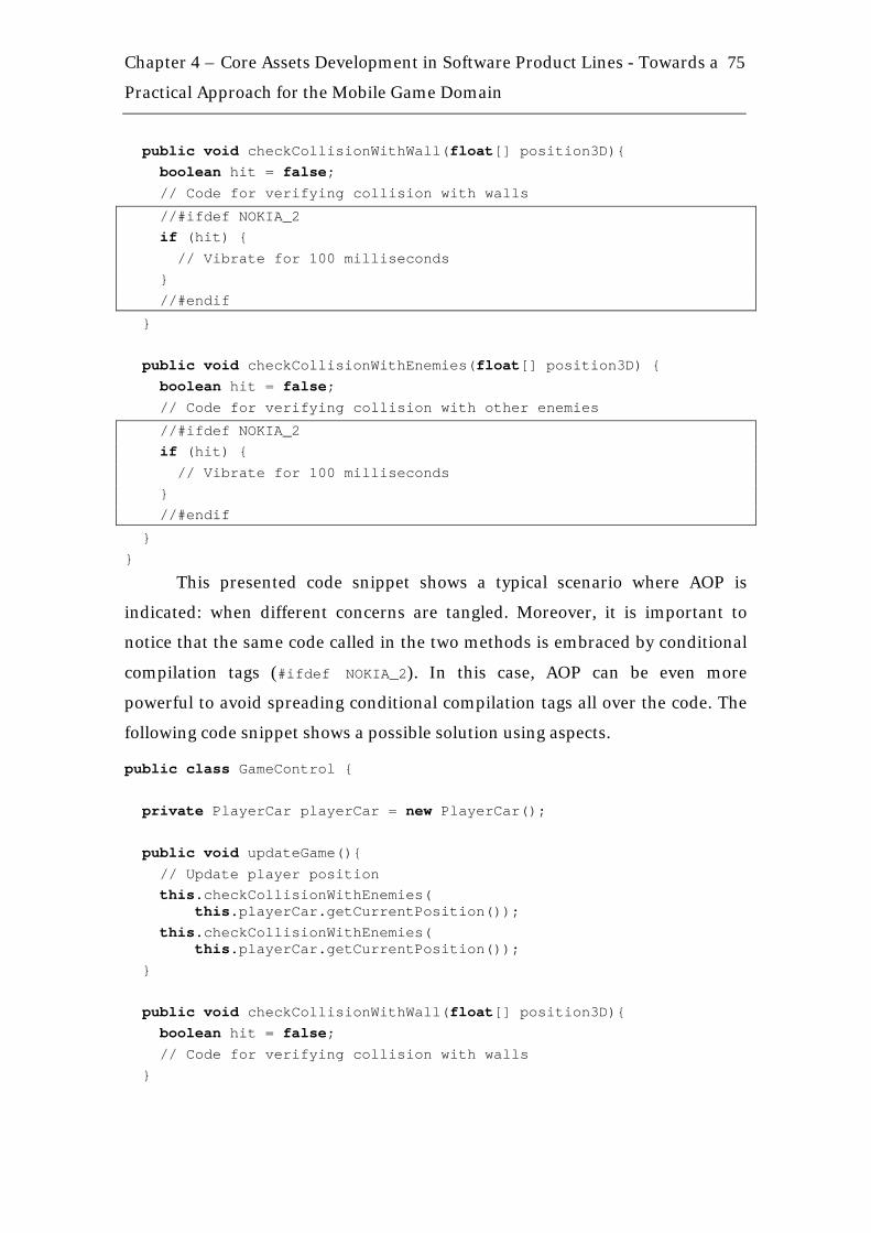
Chapter 4 – Core Assets Development in Software Product Lines - Towards a
Practical Approach for the Mobile Game Domain
75
public void checkCollisionWithWall(float[] position3D){ boolean hit = false; // Code for verifying collision with walls
//#ifdef NOKIA_2 if (hit) { // Vibrate for 100 milliseconds } //#endif
} public void checkCollisionWithEnemies(float[] position3D) { boolean hit = false; // Code for verifying collision with other enemies
//#ifdef NOKIA_2 if (hit) { // Vibrate for 100 milliseconds } //#endif
} }
This presented code snippet shows a typical scenario where AOP is
indicated: when different concerns are tangled. Moreover, it is important to
notice that the same code called in the two methods is embraced by conditional
compilation tags (#ifdef NOKIA_2). In this case, AOP can be even more
powerful to avoid spreading conditional compilation tags all over the code. The
following code snippet shows a possible solution using aspects.
public class GameControl { private PlayerCar playerCar = new PlayerCar(); public void updateGame(){ // Update player position this.checkCollisionWithEnemies( this.playerCar.getCurrentPosition()); this.checkCollisionWithEnemies( this.playerCar.getCurrentPosition()); } public void checkCollisionWithWall(float[] position3D){ boolean hit = false; // Code for verifying collision with walls }
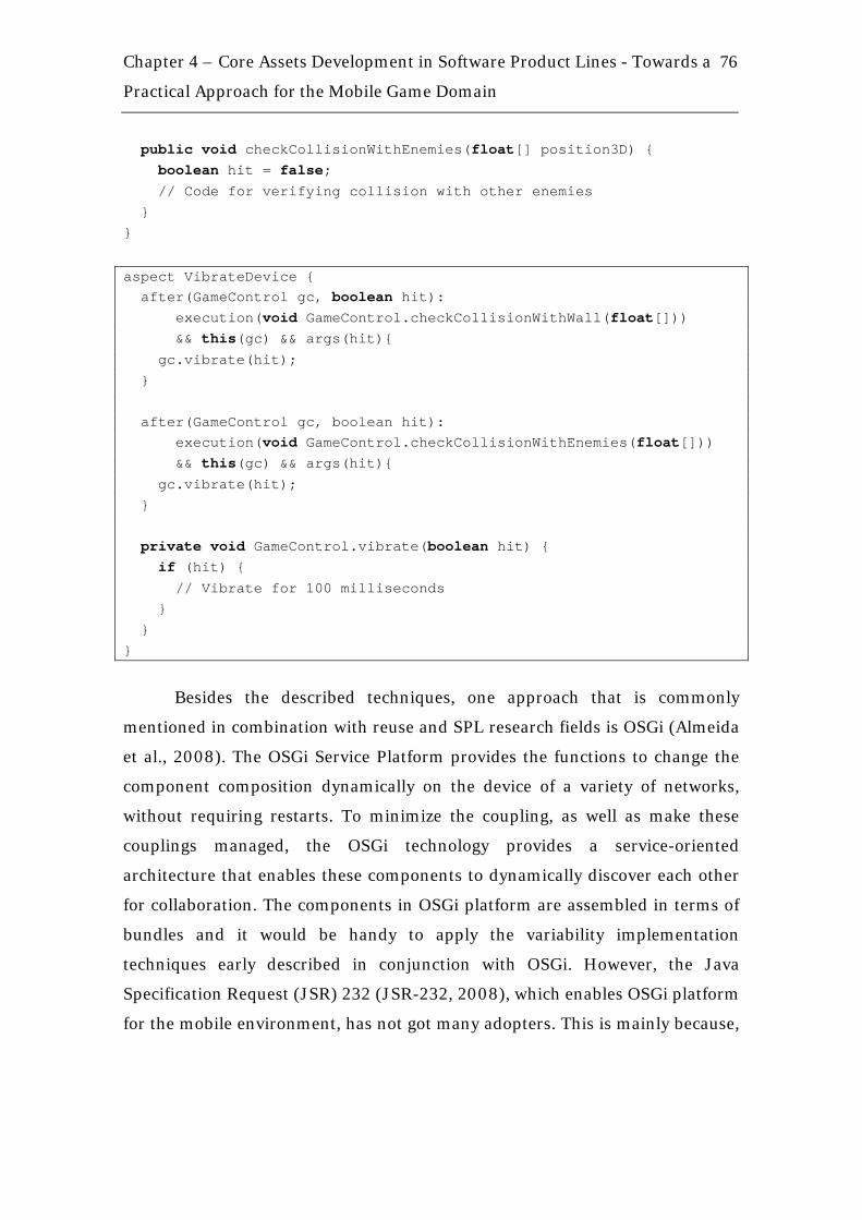
Chapter 4 – Core Assets Development in Software Product Lines - Towards a
Practical Approach for the Mobile Game Domain
76
public void checkCollisionWithEnemies(float[] position3D) { boolean hit = false; // Code for verifying collision with other enemies } }
aspect VibrateDevice { after(GameControl gc, boolean hit): execution(void GameControl.checkCollisionWithWall(float[])) && this(gc) && args(hit){ gc.vibrate(hit); } after(GameControl gc, boolean hit): execution(void GameControl.checkCollisionWithEnemies(float[])) && this(gc) && args(hit){ gc.vibrate(hit); } private void GameControl.vibrate(boolean hit) { if (hit) { // Vibrate for 100 milliseconds } } }
Besides the described techniques, one approach that is commonly
mentioned in combination with reuse and SPL research fields is OSGi (Almeida
et al., 2008). The OSGi Service Platform provides the functions to change the
component composition dynamically on the device of a variety of networks,
without requiring restarts. To minimize the coupling, as well as make these
couplings managed, the OSGi technology provides a service-oriented
architecture that enables these components to dynamically discover each other
for collaboration. The components in OSGi platform are assembled in terms of
bundles and it would be handy to apply the variability implementation
techniques early described in conjunction with OSGi. However, the Java
Specification Request (JSR) 232 (JSR-232, 2008), which enables OSGi platform
for the mobile environment, has not got many adopters. This is mainly because,
Chapter 4 – Core Assets Development in Software Product Lines - Towards a
Practical Approach for the Mobile Game Domain
77
to enable OSGi, deep changes would be necessary in the MIDlet6 life cycle
manager to let two different JME applications share the same resources, such as
a shared component library. Moreover, OSGi needs at least a Connected Device
Configuration (CDC) to run and the majority of mobile phones only implement
Connected Limited Device Configuration (CLDC). For now, few JSR-232
capable handsets have been announced by the main manufacturers making the
usage of OSGi in the mobile applications environment not practical.
Based on component specification (structural model) as mentioned in the
last section, and also on the product portfolio and product map descriptions
considering the conditional compilation tags, the developers can implement the
reusable components (SPL core assets) following the guidelines described in
this section. It is important to mention that this work is not focused on
providing a decision model to aid on choosing which variability implementation
technique is the more appropriate to be used in a given context. After
implementation, developers should update components documentation in
conjunction with internal design to reflect the information in product map and
portfolio. This documentation should provide the following information:
• Groups of conditional compilation tags and the respective dependencies
among them: specifying which are the dependencies among the tags in
the components code may facilitate the deployment of new products and
the use of a tool to automate the deployment process.
• Memory usage: an estimation of how much memory the components
consume can help to decide whether the final application can be suitable
for a given handset or not.
• Total component size in JAR file: the components size may vary
according to the conditional compilation tags used in deployment
process. So, it is important to provide the information about how big is a
component in terms of which group of conditional compilation tags was
used to build it up.
6 Every JME application is defined by a MIDlet, It is the basic class that allows the Java Virtual Machine to initiate a JME application. It is equivalent to the main method of a Java Standard Edition (JSE) application
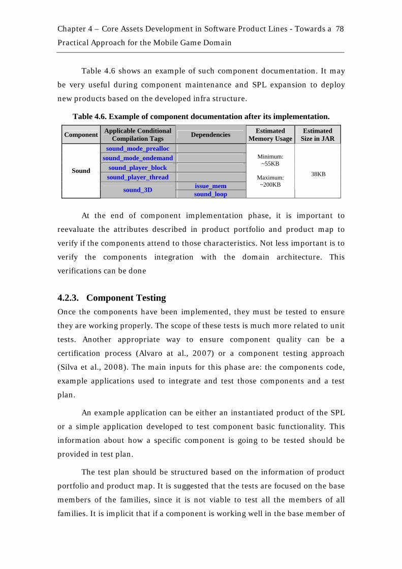
Chapter 4 – Core Assets Development in Software Product Lines - Towards a
Practical Approach for the Mobile Game Domain
78
Table 4.6 shows an example of such component documentation. It may
be very useful during component maintenance and SPL expansion to deploy
new products based on the developed infra structure.
Table 4.6. Example of component documentation after its implementation.
Component Applicable Conditional Compilation Tags Dependencies Estimated
Memory Usage Estimated
Size in JAR sound_mode_prealloc
sound_mode_ondemand sound_player_block
sound_player_thread issue_mem
Sound
sound_3D sound_loop
Minimum: ~55KB
Maximum:
~200KB
38KB
At the end of component implementation phase, it is important to
reevaluate the attributes described in product portfolio and product map to
verify if the components attend to those characteristics. Not less important is to
verify the components integration with the domain architecture. This
verifications can be done
4.2.3. Component Testing Once the components have been implemented, they must be tested to ensure
they are working properly. The scope of these tests is much more related to unit
tests. Another appropriate way to ensure component quality can be a
certification process (Alvaro at al., 2007) or a component testing approach
(Silva et al., 2008). The main inputs for this phase are: the components code,
example applications used to integrate and test those components and a test
plan.
An example application can be either an instantiated product of the SPL
or a simple application developed to test component basic functionality. This
information about how a specific component is going to be tested should be
provided in test plan.
The test plan should be structured based on the information of product
portfolio and product map. It is suggested that the tests are focused on the base
members of the families, since it is not viable to test all the members of all
families. It is implicit that if a component is working well in the base member of

Chapter 4 – Core Assets Development in Software Product Lines - Towards a
Practical Approach for the Mobile Game Domain
79
the family, it will work properly on the other members of that family. At least, it
is what is expected from the handset manufacturers when they produce
different handsets of the same family and usually with the same hardware
platform.
Depending on how test plan is made, it can be similar to a specific
product test plan, for example, testing specific functionality of a component in
Motorola handsets using specific steps. In summary, it means that specific
variabilities are supposed to be tested in test plans of specific products. In
addition, there should be a domain test plan, which is related to the domain
commonalities among different families of handsets and this test plan can be
used across the different families. This work does not focus on component
testing as different works have been exploring issues related to the subject. For
further investigation on component testing issues, there is one work at RiSE
group that aims directly on that (Silva et al., 2008).
4.3. Chapter Summary In this chapter, it was described a practical approach for implementing core
assets in the mobile game domain. The approach is intended to supply the lack
of details in domain implementation phase of other SPL processes, detailed in
Chapter 3, and to cover the restrictions of the mobile game domain. These
restrictions are, for example, the short schedules of mobile game projects, the
big diversity of target handsets, which causes diverse problems involving
hardware restrictions, processing power, memory size and application size, and
the different API implementations. The approach is divided in three main
phases (Component Modeling, Component Implementation and Component
Testing) and clearly defines activities, inputs, outputs, and roles, as shown in
Table 4.7. Guidelines are provided throughout the Component Implementation
phase in order to ease the approach understanding and adoption.
Some related work could be identified in this research. As it was already
mentioned, Chapter 3 shows nine SPL processes and seven domain engineering
processes, all of them considered relevant to the software reuse field, but they
still need adaptations to be properly used in the mobile applications domain.

Chapter 4 – Core Assets Development in Software Product Lines - Towards a
Practical Approach for the Mobile Game Domain
80
Moreover, some related work specifically in the mobile game domain could be
identified, including an adaptation of a SPL process to the mobile domain,
refactoring tools and strategies to use aspect-oriented programming to structure
a product line. Related work is discussed with more details in Chapter 6.
Table 4.7. Summary of the approach for core assets development in a SPL applied to the mobile game domain.
Phases Activities Inputs Outputs Roles Domain
architecture (including
components identification)
Specify components’
internal design Domain feature
model
Components’ internal design with possible conditional
compilation tags Component Modeling
Refine product map with
conditional compilation tags
Product portfolio and product map
Refined product map
Domain expert, domain architect
and possibly developers
Domain architecture
Domain feature model
Code and document
components Components’ internal design
Components’ code and
documentation associated
Developers
Component Implementation Refine
conditional compilation tags
in product map, if applicable
Product portfolio and product map
Possibly refined product map
Domain architect
Product portfolio and product map Specify test cases Components’ internal design
Domain test cases and application-
specific test cases
Testers with possible
developers help
Components’ code and
documentation associated
Component Testing
Execute test cases
Example Applications
Test results Testers
In the next chapter, an experimental study is described in details in order
to evaluate the proposed approach.
5 An Experimental Study in the Mobile Game Domain
“Progress comes from the intelligent use of experience”
Elbert Hubbard (1856 – 1915) American writer and philosopher
The information technology revolution has meant, among other things, that
software has become a part of more and more products ranging from toasters to
space shuttles. It indicates that a vast amount of software has been and is being
developed. However, software development is not an easy task; it is a highly
creative activity (Glass & DeMarco, 2006) which demands the use of a software
process. According to (IEEE Std, 1990), a software process is “the application of
a systematic, disciplined, quantifiable approach to development, operation
and maintenance of software”. Considering the benefits of the use a software
process can bring, such as productivity gains and cost reductions (Rozum,
1993), organizations are continuously trying to improve their software process.
In this context, for a software company to achieve the necessary
improvements of its software process, it needs a systematic and disciplined
approach of working (Wohlin et al., 2000).
One problem that arises is that a process improvement is very hard to
evaluate without human involvement directly. In the case of products, it is
possible to build a prototype to evaluate it. However, for a process it is not
possible to build a prototype. It is possible to make simulations and compare
different processes, but it should be remembered that this is still an evaluation
based on a model. The real evaluation of a process or process improvement is to
Chapter 5 – An Experimental Study in the Mobile Game Domain
82
have people using it (Wohlin et al., 2000). Empirical studies are crucial to the
evaluation of processes and human-based activities. In addition,
experimentation provides a systematic, disciplined, quantifiable and controlled
way of evaluating human-based activities (Wohlin et al., 2000). It has been used
in many fields, e.g., physics, medicine, manufacturing, however, in the software
engineering field, this idea started to be explored in the 1970s with the work of
Victor Robert Basili from University of Maryland (Boehm et al., 2005).
According to (Basili, 1996), like other disciplines, software engineering
requires the same high level approach for evolving the knowledge of the
discipline: the cycle of model building, experimentation and teaming, since we
cannot rely solely on observation followed by logical thought. It involves an
experimental component in order to test or disprove theories, to explore new
domains.
Therefore, this chapter presents an experimental study in order to
evaluate the approach proposed in Chapter 4 involving core assets
implementation in the mobile game domain. Before the actual description of the
experimental study, some definitions are introduced to clarify the whole
experiment.
5.1. Introduction To execute an experimental study, (Wohlin et al., 2000) proposed a process that
should be followed, which is composed of five phases: definition, planning,
operation, analysis and interpretation, and optionally presentation
and package.
Conducting an experiment is a labor-intensive task. The purpose of the
definition phase is to define the goals of an experiment, helping on better
scoping the activities during the whole experiment. For defining the goals of the
experiment, the Goal Question Metric (GQM) (Basili et al., 1994) approach is
followed. The approach is based upon the assumption that for an organization
to measure in a purposeful way it must first specify the goals for itself and its
projects, then it must trace those goals to the data that are intended to define
those goals operationally, and finally provide a framework for interpreting the
data with respect to the stated goals. The result of the application of the GQM
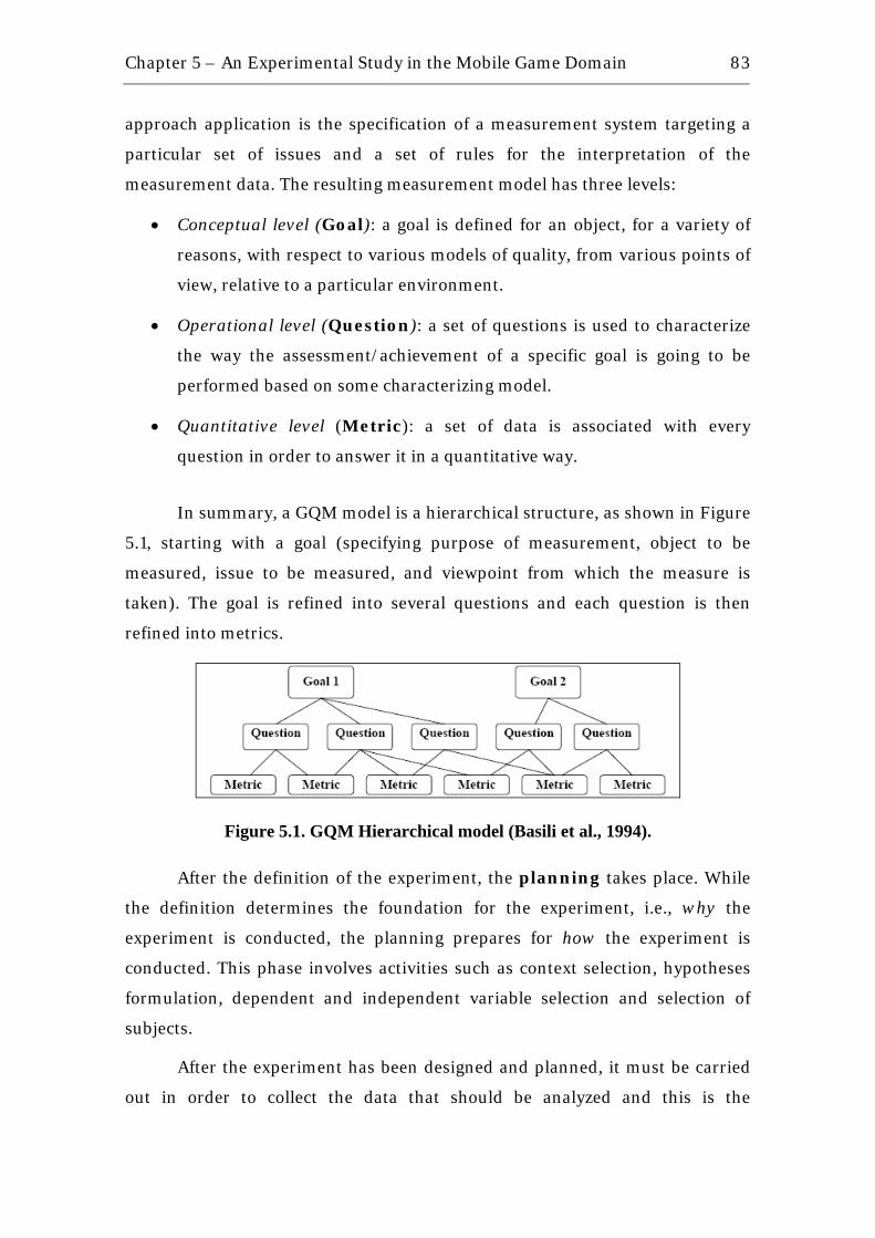
Chapter 5 – An Experimental Study in the Mobile Game Domain
83
approach application is the specification of a measurement system targeting a
particular set of issues and a set of rules for the interpretation of the
measurement data. The resulting measurement model has three levels:
• Conceptual level (Goal): a goal is defined for an object, for a variety of
reasons, with respect to various models of quality, from various points of
view, relative to a particular environment.
• Operational level (Question): a set of questions is used to characterize
the way the assessment/achievement of a specific goal is going to be
performed based on some characterizing model.
• Quantitative level (Metric): a set of data is associated with every
question in order to answer it in a quantitative way.
In summary, a GQM model is a hierarchical structure, as shown in Figure
5.1, starting with a goal (specifying purpose of measurement, object to be
measured, issue to be measured, and viewpoint from which the measure is
taken). The goal is refined into several questions and each question is then
refined into metrics.
Figure 5.1. GQM Hierarchical model (Basili et al., 1994).
After the definition of the experiment, the planning takes place. While
the definition determines the foundation for the experiment, i.e., why the
experiment is conducted, the planning prepares for how the experiment is
conducted. This phase involves activities such as context selection, hypotheses
formulation, dependent and independent variable selection and selection of
subjects.
After the experiment has been designed and planned, it must be carried
out in order to collect the data that should be analyzed and this is the
Chapter 5 – An Experimental Study in the Mobile Game Domain
84
operation phase of an experiment. After preparing the experimental
environment, the experiment is executed and, in this phase, it is when the
subjects are actually involved. At the end of this phase, measurements are
collected.
After collecting experimental data in the operation phase, it is necessary
to draw conclusions based on this data and so analysis and interpretation
phase takes place. The main goal of this phase is to analyze the data by
hypothesis testing.
Finally, an optional phase may be performed to help on presenting the
findings of the experiment. The presentation and package phase helps on
structuring reports of the experiment for improving understanding and
interpretation of possible readers.
5.2. The Experimental Study Following the organization proposed by (Wohlin et al., 2000), we structured an
experimental study to evaluate the practical application of the approach
described in the last chapter in the mobile game domain. Sometimes the future
tense is used, symbolizing the precedence of the plan in relation to its execution.
5.2.1. The Definition As afore mentioned, the definition phase of the experimental study uses the
GQM paradigm (Basili et al., 1994). The following subsections present the goals,
questions and metrics for the experiment.
5.2.1.1. Goal G1. To evaluate the approach for core assets development in a SPL
applied to the mobile game domain in terms of efficiency and appropriate
management of domain restrictions, including traceability from domain
features to code level, from the point of view of practitioner in the context of
software product line projects.

Chapter 5 – An Experimental Study in the Mobile Game Domain
85
5.2.1.2. Questions Q1. Does the approach generate components with low complexity?
Q2. Does the approach manage the domain restrictions, such as
application size, different screen sizes and different API implementations?
Q3. Can the approach map domain features to code level?
5.2.1.3. Metrics M1. Component Complexity. A challenge in software engineering is
related to how to modularize a system in order to result in modules or
components that are well defined, testable and maintainable. During the 70s,
McCabe developed a mathematical technique (McCabe, 1976), providing a
quantitative basis for modularization and identifying software modules that will
be difficult to test or maintain. In this technique, the complexity is measured in
terms of the number of paths through a program, called cyclomatic complexity.
This measure is also useful to keep the size of the modules manageable and
allow the testing of all the independent paths. Therefore, the component
complexity metric will be defined in terms of cyclomatic complexity, which is
calculated from a connected graph of the module (or component):
CC(G) = E – N + p, where:
E = the number of edges of the graph
N = the number of nodes of the graph
P = the number of connected components
The properly interpretation of this metric, based on research performed
in the Software Engineering Institute (SEI, 1997), is based on four different
intervals for the values: 1 and 10, it is a simple program, without much risk;
between 11 and 20, it represents a more complex program, with moderate risk;
between 21 and 50 represent, it is a complex program, with high risk; and
greater than 50, which represents a program impossible to be tested and
presents a high risk.
We decided to use classic Object Orientation metrics to evaluate the
process because they are more well-established after years of experience with
case studies and experiments. Reuse-specific metrics, although more suited to
Chapter 5 – An Experimental Study in the Mobile Game Domain
86
this context, still needs more experimentation (Mascena et al., 2005). Moreover,
the mobile game domain has already reached a quite complex level in terms of
object oriented metrics given the diversity of handsets and increasing number of
different games. Then, the component complexity metrics can be appropriately
applicable for mobile games.
M2. Domain Restrictions Management. As it was already
mentioned, the mobile applications domain has specific characteristics different
from other domains, which may restrict the use of a SPL approach. In order to
make feasible the application of such approach, the restrictions related to
application size, different screen sizes and different API implementations, for
example, must be considered. In this context, three metrics related to
restrictions managements can be used:
NFA: %Product families which have the restriction of application size
mapped at code level.
NFS: %Product families which have the restriction of different screen
sizes mapped at code level.
NFI: %Product families which have the restriction of different API
implementations mapped at code level.
As these metrics have never been used before, there are no well known
values for them. The practical experience in projects in this direction at the
Recife Center for Advanced Studies and Systems (C.E.S.A.R)1 and common
sense were used to define these values. Thus, a percentage above 50% for all
three metrics is considered as a good indicative that the approach can manage
the mobile applications restrictions.
M3. Traceability Level. One of the main concerns related to software
processes is the traceability among artifacts. In practice, however, some artifacts
may not be traceable. For example, a domain feature model presents five main
features, but these features may not be traced to the defined components and
also the variabilities of these features can not be traced to code level. In this
context, maintaining traceability between features and code artifacts in a high 1 Recife Center for Advanced Studies and System – C.E.S.A.R, available on http://www.cesar.org.br, accessed in January, 2008.
Chapter 5 – An Experimental Study in the Mobile Game Domain
87
level can bring evidences that an appropriate level of details has been used in
the phases of the process related to artifacts implementation. In order to better
managing the traceability among artifacts and the appropriateness of process’
level of details in the phases related to artifacts implementation, two metrics are
defined:
TFComp: %Features that can be mapped to components.
TFCode: %Features that can be mapped to code (respective conditional
compilation tags).
Also based on practical experience, as mentioned in metric M2, an
acceptable value for the two metrics of traceability level is a value above 70%.
5.2.2. The Planning After the definition of the experimental study, the planning is started. The
definition determines the foundations for the experiment, the reason for it,
while the planning prepares for how the experiment is conducted.
Context. The objective of the experimental study is to evaluate the SPL
approach in a mobile game project. This project will be conducted in a
university laboratory with the requirements defined by experienced staff based
on real-world projects. The study will be conducted as single object study which
is characterized as being a study which examines an object on a single team and
a single project (Basili et al., 1986).
Training. It is assumed that the subjects are already familiarized with
concepts related to software reuse, such as, variability, component-based
development, domain engineering and software product lines and, then, they
can understand the proposed approach by only reading it, without the necessity
of training.
Pilot Project. Before performing the study, a pilot project will be
conducted with the same structure defined in this planning. The pilot project
will be performed by a single subject, who is already familiarized with the
proposed approach. In this way, the pilot project will be a study based on
observation, aiming to detect problems and improve the proposed approach.
Chapter 5 – An Experimental Study in the Mobile Game Domain
88
Subjects. The subjects of the study will be requested to act as the roles
defined in the approach (domain expert, domain analyst, domain architect,
developer and tester). Nevertheless, during the project, one subject can have
more than one role depending of the context, e.g., domain analyst in the
beginning and domain architect in next the step.
Instrumentation. All the subjects will have access to the guidelines
provided by the proposed approach in order to better implementing the core
assets.
Criteria. Some criteria will be used in order to evaluate the benefits of
the approach and its appropriateness for the domain being explored. The
benefits will be evaluated quantitatively in terms of components complexity,
using McCabe cyclomatic complexity, domain restrictions management and
traceability, by observing product map and portfolio and its correspondence to
implemented code.
Null Hypotheses. These are the hypotheses that the experimenter
wants to reject with as high significance as possible. Therefore, according to the
selected criteria, the following hypotheses can be defined:
H0: μthe approach generates components with CC >= 21
H0: μNFA <= 50%
H0: μNFS <= 50%
H0: μNFI <= 50%
H0: μTFComp <= 70%
H0: μTFCode <= 70%
Alternative Hypotheses. These are the hypotheses in favor of which
the null hypotheses are rejected. Thus, the following hypotheses can be defined:
H1: μthe approach generates components with CC < 21
H1: μNFA > 50%
H1: μNFS > 50%
H1: μNFI > 50%
Chapter 5 – An Experimental Study in the Mobile Game Domain
89
H1: μTFComp > 70%
H1: μTFCode > 70%
Independent variables. The independent variable considered in this
experimental study is the expertise of the subjects in the mobile applications
domain. The expertise is measured in terms of the subjects experience in the
software reuse area and mobile domain through interviews.
Dependent variables. The dependent variables are the quality of the
components and product map/portfolio information, as well as the number of
product families. The components quality will be measured by their complexity
(McCabe cyclomatic complexity). The product map/portfolio quality will be
measured by the traceability level and the number of families will be measured
in terms of domain restrictions management.
Randomization. This technique can be used in the selection of the
subjects. Ideally, the subjects must be selected randomly from a set of
candidates (Wohlin et al., 2000). In this study, it was not necessary to
randomize the subjects, once the approach focus on people with expertise in the
mobile domain.
Blocking. Sometimes, there is a factor that probably has an effect on the
response, but the experimenter is not interested in that effect. If the effect on
the factor is known and controllable, is possible to use a design technique called
blocking. Blocking is used to systematically eliminate the undesired effect in the
comparison among the treatments. In this study, it was not identified the
necessity of dividing the subjects into blocks, since the study will evaluate just
one factor, which is the use of the approach.
Balancing. In some experiments, balancing is desirable because it
simplifies and strengthens the statistical analysis of the data. However, in this
study it is not necessary to divide the subjects, since there is only one group.
Internal Validity. The internal validity of the study is defined as the
capacity of a new study to repeat the behavior of the current study, with the
same subjects and objects with which it was executed (Wohlin et al., 2000). The
internal validity of this study is dependent of the number of target handsets,
Chapter 5 – An Experimental Study in the Mobile Game Domain
90
because the approach is not intended to specifically handle activities of porting
mobile applications to a big number of target handsets. To guarantee a good
internal validity, this study is supposed to handle at most 5 different families of
handsets with at most 5 target handsets arranged in each family. This is an
empirical number from practical experience to avoid the approach to be focused
only on applications porting.
External Validity. The external validity of the study measures its
capability to be affected by the generalization, i.e., the capability to repeat the
same study in other research groups (Wohlin et al., 2000). In this study, a
possible problem related to the external validity is the subjects’ motivation,
since some subjects can perform the study without responsibility or without a
real interest in programming, which is a heavy executed activity in an industrial
mobile game project. The external validity of the study is considered sufficient,
since the subjects are previously selected with experience in the mobile game
domain which implies they are motivated.
Construct Validity. The validation of the construction of the study
refers to the relation between the theory that is to be proved and the
instruments and subjects of the study (Wohlin et al., 2000). In this study, the
problem domain was previously chosen as the main focus of the proposed
approach considering the experience of the subjects involved. Therefore, this
choice avoids wrong interpretation of the impact of the approach.
Conclusion Validity. This validity is concerned with the relationship
between the treatment and the outcome, and determines the capability of the
study to generate conclusions (Wohlin et al., 2000). The conclusions of this
study will be drawn by the use of descriptive statistic.
5.2.3. The Project Used in the Study In this study, three games of the same domain will be used, all of them from
Meantime2, a mobile game producer headquartered in Recife: Monga,
American Dad – Roger’s Scape and Zaak. Figure 5.2 shows a screenshot of each
game. Based on the features and consequently code from the early cited games,
2 Meantime Mobile creations, available on http://www.meantime.com.br, accessed in January, 2008.
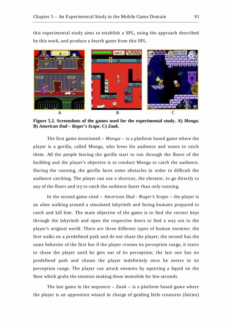
Chapter 5 – An Experimental Study in the Mobile Game Domain
91
this experimental study aims to establish a SPL, using the approach described
by this work, and produce a fourth game from this SPL.
Figure 5.2. Screenshots of the games used for the experimental study. A) Monga. B) American Dad – Roger’s Scape. C) Zaak.
The first game mentioned – Monga – is a platform based game where the
player is a gorilla, called Monga, who loves his audience and wants to catch
them. All the people fearing the gorilla start to run through the floors of the
building and the player’s objective is to conduct Monga to catch the audience.
During the running, the gorilla faces some obstacles in order to difficult the
audience catching. The player can use a shortcut, the elevator, to go directly to
any of the floors and try to catch the audience faster than only running.
In the second game cited – American Dad - Roger’s Scape – the player is
an alien walking around a simulated labyrinth and facing humans prepared to
catch and kill him. The main objective of the game is to find the correct keys
through the labyrinth and open the respective doors to find a way out to the
player’s original world. There are three different types of human enemies: the
first walks on a predefined path and do not chase the player; the second has the
same behavior of the first but if the player crosses its perception range, it starts
to chase the player until he gets out of its perception; the last one has no
predefined path and chases the player indefinitely once he enters in its
perception range. The player can attack enemies by squirting a liquid on the
floor which grabs the enemies making them immobile for few seconds.
The last game in the sequence – Zaak – is a platform based game where
the player is an apprentice wizard in charge of guiding little creatures (fairies)
Chapter 5 – An Experimental Study in the Mobile Game Domain
92
through a world full of obstacles to an exit and save them. The player can face
enemies that keep on walking around the level in a predefined path (patroller).
In this case the enemies do not chase the player as in American Dad. The player
can attack and destroy enemies by using magic cards. Through the levels, the
player can collect different items that help on guiding the fairies to the way out,
such as ropes and leverages.
The subjects involved in the project had full access to documentation and
code. However, not so many details of the games will be provided because of
matters of confidentiality.
5.2.4. The Instrumentation Selection of Subjects. The subjects were selected by convenience
sampling (Wohlin et al., 2000) representing a non-random subset from the
universe of students of Software Engineering.
Data Validation. In this study, descriptive statistics will be used to
analyze the data set, since it may be used before carrying out hypotheses testing,
in order to better understand the nature of the data and to identify abnormal or
false data points (Wohlin et al., 2000).
Instrumentation. Before the experiment can be executed, all
experiment instruments must be ready. It includes the experiment objects,
guidelines, forms and tools. In this study, the instruments are: all the approach
documentation, including guidelines; and all artifacts used as input for the
study. These artifacts are related to the games mentioned in Section 5.2.3 (game
design document, architecture, code, executable and test cases). To protect the
Meantime’s proprietary assets, the subjects involved had to access a Non
Disclosure Agreement (NDA).
5.2.5. The Operation Experimental Environment. This study was performed in the period
from December 2007 to April 2008, at Federal University of Pernambuco, and
partially at C.E.S.A.R, Pernambuco, Brazil.
Subjects. The subjects involved were: one M.Sc. student from Federal
University of Pernambuco, acting as domain expert, domain analyst, domain
Chapter 5 – An Experimental Study in the Mobile Game Domain
93
architect, developer and tester; and his co-advisor, Ph.D. in Computer Science
at Federal University of Pernambuco (UFPE) in 2007, acting as reuse consultant
and sometimes domain expert.
Summary of Generated Artifacts. Following the approach described
in Chapter 4 with its suggested sequence of steps and considering the expected
inputs (product portfolio, product map, domain feature model and domain
architecture), the main activities during the execution of experimental study
were:
• To analyze the artifacts given as input for better understanding how the
components are going to be implemented considering the domain
restrictions and architecture structure.
• To refine the product map in order to handle the domain restrictions by
adding conditional compilation tags to each correspondent variation
level.
• To specify the components internal design taking into consideration the
conditional compilation tags described in the refined product map and
using <<variant>> stereotype to represent the variant parts of each
component.
• To implement the components based on their internal design and
following the guidelines provided by the approach proposed. At the end
of this activity, the components documentation should provide the
following information in order to reflect the restrictions detailed in
product portfolio and product map: the groups of conditional
compilation tags that were applied to the component and the respective
dependencies between them; as well as one estimation of the components
memory usage; and the total component size in JAR file.
• To test the components implemented by using an example application in
the domain, which can be a new product derived from SPL.
• To instantiate a new product based on the core assets defined.
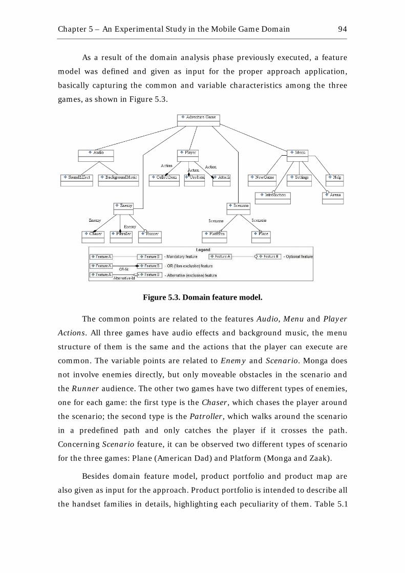
Chapter 5 – An Experimental Study in the Mobile Game Domain
94
As a result of the domain analysis phase previously executed, a feature
model was defined and given as input for the proper approach application,
basically capturing the common and variable characteristics among the three
games, as shown in Figure 5.3.
Figure 5.3. Domain feature model.
The common points are related to the features Audio, Menu and Player
Actions. All three games have audio effects and background music, the menu
structure of them is the same and the actions that the player can execute are
common. The variable points are related to Enemy and Scenario. Monga does
not involve enemies directly, but only moveable obstacles in the scenario and
the Runner audience. The other two games have two different types of enemies,
one for each game: the first type is the Chaser, which chases the player around
the scenario; the second type is the Patroller, which walks around the scenario
in a predefined path and only catches the player if it crosses the path.
Concerning Scenario feature, it can be observed two different types of scenario
for the three games: Plane (American Dad) and Platform (Monga and Zaak).
Besides domain feature model, product portfolio and product map are
also given as input for the approach. Product portfolio is intended to describe all
the handset families in details, highlighting each peculiarity of them. Table 5.1

Chapter 5 – An Experimental Study in the Mobile Game Domain
95
shows the product portfolio considering three big manufacturers in the mobile
phone industry.
Table 5.1. Product portfolio with three manufacturers listed.
Manufacturer #1: Motorola FAMILY BASE COMPATIBILITY SCREEN MIDP HEAP JAR MP3 COMMENTS
MOTO_iDEN i850 i850; i870; i880 176x206 2.0 4 Mb 4 Mb Low performance with 3D applications.
Manufacturer #2: Nokia
FAMILY BASE COMPATIBILITY SCREEN MIDP HEAP JAR MP3 COMMENTS
NOKIA_1 3220 2600; 2610; 3220; 6020; 6021; 6030 128x128 2.0 512 kb 128 kb
Big market in Korea. Applications must include Korean language.
NOKIA_N N73 N73, N76, N80, N83, N95 240x320 2.0 No
Limit No
Limit
Symbian-based phones. Hardware acceleration for 3D applications.
Manufacturer #3: Sony Ericsson
FAMILY BASE COMPATIBILITY SCREEN MIDP HEAP JAR MP3 COMMENTS
SE_1 P900 P800; P802; P900; P908; P910 208x320 1.0 512 kb 1 Mb
PRIORITY MEMBER BASE COMMENTS
1 MOTO_iDEN i850 An early release is needed for this family requested by client
2 NOKIA_1 3220 Mobile phones with many hardware restrictions get a higher priority because it is easier to expand the application to a less restrict platform than to shrink the application to a more restrict platform
3 NOKIA_N N73 High-end phones get a low priority because they have few hardware constraints and there is no real need for code optimization
4 SE_1 P900 Small market
Moreover, product map describes the generic capabilities of the handsets
with the appropriate variation levels mapping each of them to the respective
families. As proposed in Chapter 4, product map should be refined by adding
conditional compilation tags and mapping them to each specific variation levels
specified. As a result of this refinement, Table 5.2 shows the product map with
the conditional compilation tags already attached. It is possible to use a feature
model to represent the product map just as shown in Figure 5.3, however,
structuring the product map in the way it is shown in Table 5.2 gives the
possibility of adding as more comments as necessary to make the handset
capabilities more clear. In the sequence, Table 5.3 shows the groups of
conditional compilation tags mapped to each product family.
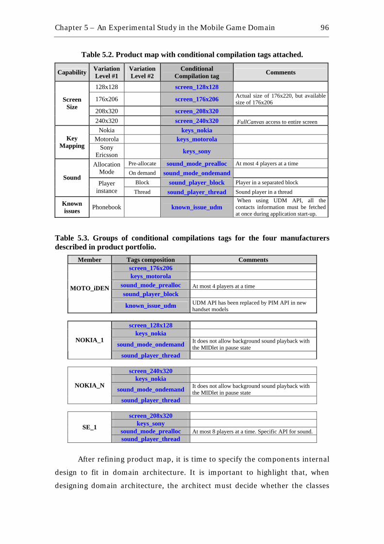
Chapter 5 – An Experimental Study in the Mobile Game Domain
96
Table 5.2. Product map with conditional compilation tags attached.
Capability Variation Level #1
Variation Level #2
Conditional Compilation tag Comments
128x128 screen_128x128
176x206 screen_176x206 Actual size of 176x220, but available size of 176x206
208x320 screen_208x320
Screen Size
240x320 screen_240x320 FullCanvas access to entire screen Nokia keys_nokia
Motorola keys_motorola Key Mapping Sony
Ericsson keys_sony Pre-allocate sound_mode_prealloc At most 4 players at a time Allocation
Mode On demand sound_mode_ondemand Block sound_player_block Player in a separated block
Sound Player
instance Thread sound_player_thread Sound player in a thread
Known issues Phonebook known_issue_udm
When using UDM API, all the contacts information must be fetched at once during application start-up.
Table 5.3. Groups of conditional compilations tags for the four manufacturers described in product portfolio.
Member Tags composition Comments screen_176x206 keys_motorola
sound_mode_prealloc At most 4 players at a time sound_player_block
MOTO_iDEN
known_issue_udm UDM API has been replaced by PIM API in new handset models
screen_128x128
keys_nokia
sound_mode_ondemand It does not allow background sound playback with the MIDlet in pause state
NOKIA_1
sound_player_thread
screen_240x320 keys_nokia
sound_mode_ondemand It does not allow background sound playback with the MIDlet in pause state
NOKIA_N
sound_player_thread
screen_208x320 keys_sony
sound_mode_prealloc At most 8 players at a time. Specific API for sound. SE_1
sound_player_thread
After refining product map, it is time to specify the components internal
design to fit in domain architecture. It is important to highlight that, when
designing domain architecture, the architect must decide whether the classes
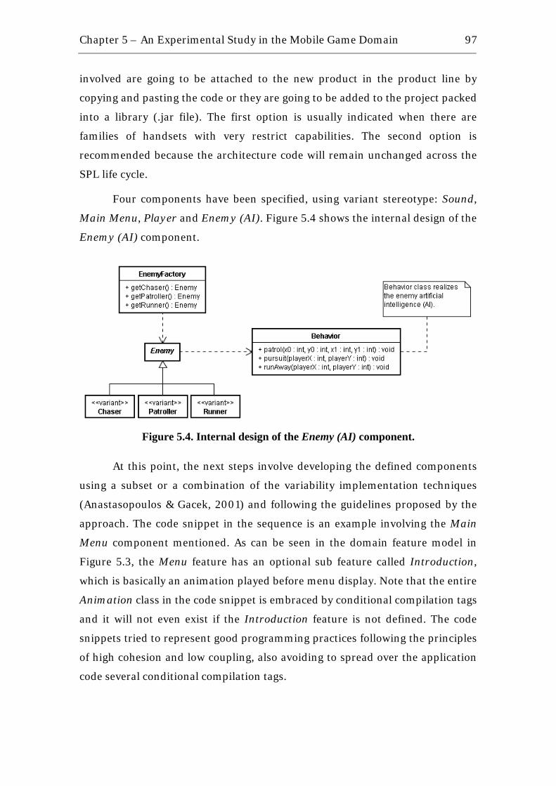
Chapter 5 – An Experimental Study in the Mobile Game Domain
97
involved are going to be attached to the new product in the product line by
copying and pasting the code or they are going to be added to the project packed
into a library (.jar file). The first option is usually indicated when there are
families of handsets with very restrict capabilities. The second option is
recommended because the architecture code will remain unchanged across the
SPL life cycle.
Four components have been specified, using variant stereotype: Sound,
Main Menu, Player and Enemy (AI). Figure 5.4 shows the internal design of the
Enemy (AI) component.
Figure 5.4. Internal design of the Enemy (AI) component.
At this point, the next steps involve developing the defined components
using a subset or a combination of the variability implementation techniques
(Anastasopoulos & Gacek, 2001) and following the guidelines proposed by the
approach. The code snippet in the sequence is an example involving the Main
Menu component mentioned. As can be seen in the domain feature model in
Figure 5.3, the Menu feature has an optional sub feature called Introduction,
which is basically an animation played before menu display. Note that the entire
Animation class in the code snippet is embraced by conditional compilation tags
and it will not even exist if the Introduction feature is not defined. The code
snippets tried to represent good programming practices following the principles
of high cohesion and low coupling, also avoiding to spread over the application
code several conditional compilation tags.

Chapter 5 – An Experimental Study in the Mobile Game Domain
98
//#ifdef animation_feature class Animation { void play(){ this.playShortAnim(); this.playLongAnim(); } void playShortAnim(){ //#ifdef short_anim //... //endif } void playLongAnim(){ //#ifdef long_anim //... //endif } } //#endif
Another example of combination of inheritance and conditional
compilation is shown in the following code snippet extracted from Enemy (AI)
component. Note that the entire subclass has to be embraced by conditional
compilation tags in order to reduce final application size.
public abstract class Enemy { public abstract void doAction(); } //#ifdef scr_130x130 class Patroller extends Enemy{ public void doAction () { Behavior.patrol(0, 0, 20, 30); // Patrols a square from 0, 0 to 20, 30 } } //#endif //#if scr_240x320 | scr_176x206 | scr_208x320 class Chaser extends Enemy { public void doAction () { // Set x, y values Behavior.pursuit(x, y); // x and y are the current player position } } //#endif

Chapter 5 – An Experimental Study in the Mobile Game Domain
99
With the components defined and implemented, the test team must use
an example application to test each component considering the families
described in product portfolio. Each component should be tested using a
representative member of the family as it would be very time consuming to test
the components using every handset in the family and the vendor must ensure
compatibility amongst all members of a family. In this study, the components
were tested within the fourth game derived from the SPL defined and worked
properly, attending to the desired functionality.
The last step is to perform a typical application engineering phase,
described in details by different authors (Clements & Northrop, 2001), (Pohl et
al., 2005), (Gomaa, 2005), in order to derive the fourth game. Based on all the
knowledge from the domain, i.e., the three games already developed, the feature
model, the domain restrictions and the previous experience with other games,
the fourth game was specified. The game was named Smart Escape. It is a
platform based game where the player needs to escape from the enemies
jumping on the horizontal platforms and collecting as more diamonds as
possible until he enters the exit door. The enemies have two predefined
behaviors: some of them only patrol a predefined path and others chase the
player when the player jumps on the platform they are currently walking on.
The chaser enemy stops chasing the player if he gets back to the base platform,
where he starts the level. The player is unable to attack the enemies. The game
finishes when all the doors of all levels are reached.
The Figure 5.5 shows which features were selected from the domain
feature model, presented in Figure 5.3, in order to derive the Smart Escape
game. In the sequence, Figure 5.6 shows the main game screen. Some artifacts
were reused from the other games, such as images and sound effects.

Chapter 5 – An Experimental Study in the Mobile Game Domain
100
Figure 5.5. Smart Escape application feature model based on the domain feature model.
Figure 5.6. Smart Escape’s main game screen.
In summary, the basic domain architecture has been implemented with
6489 lines of non-commented source code distributed in 277 methods as shown
in Table 5.4. Besides, Table 5.5 shows an overview of the four components that
were developed.
Table 5.4. Basic domain architecture overview.
Class Lines of non-commented source code Number of methods
All 6489 277 Screen 554 12
GameScreen 120 8 GameControl 193 18
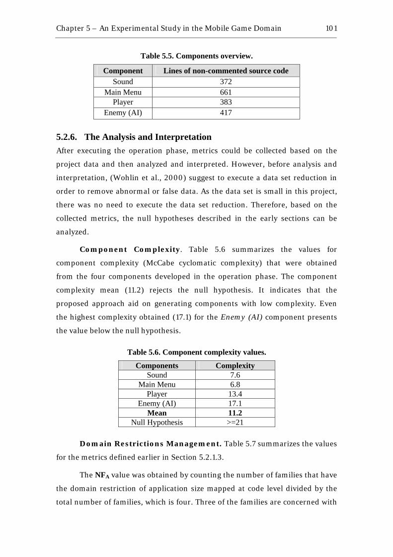
Chapter 5 – An Experimental Study in the Mobile Game Domain
101
Table 5.5. Components overview.
Component Lines of non-commented source code Sound 372
Main Menu 661 Player 383
Enemy (AI) 417
5.2.6. The Analysis and Interpretation After executing the operation phase, metrics could be collected based on the
project data and then analyzed and interpreted. However, before analysis and
interpretation, (Wohlin et al., 2000) suggest to execute a data set reduction in
order to remove abnormal or false data. As the data set is small in this project,
there was no need to execute the data set reduction. Therefore, based on the
collected metrics, the null hypotheses described in the early sections can be
analyzed.
Component Complexity. Table 5.6 summarizes the values for
component complexity (McCabe cyclomatic complexity) that were obtained
from the four components developed in the operation phase. The component
complexity mean (11.2) rejects the null hypothesis. It indicates that the
proposed approach aid on generating components with low complexity. Even
the highest complexity obtained (17.1) for the Enemy (AI) component presents
the value below the null hypothesis.
Table 5.6. Component complexity values.
Components Complexity Sound 7.6
Main Menu 6.8 Player 13.4
Enemy (AI) 17.1 Mean 11.2
Null Hypothesis >=21
Domain Restrictions Management. Table 5.7 summarizes the values
for the metrics defined earlier in Section 5.2.1.3.
The NFA value was obtained by counting the number of families that have
the domain restriction of application size mapped at code level divided by the
total number of families, which is four. Three of the families are concerned with
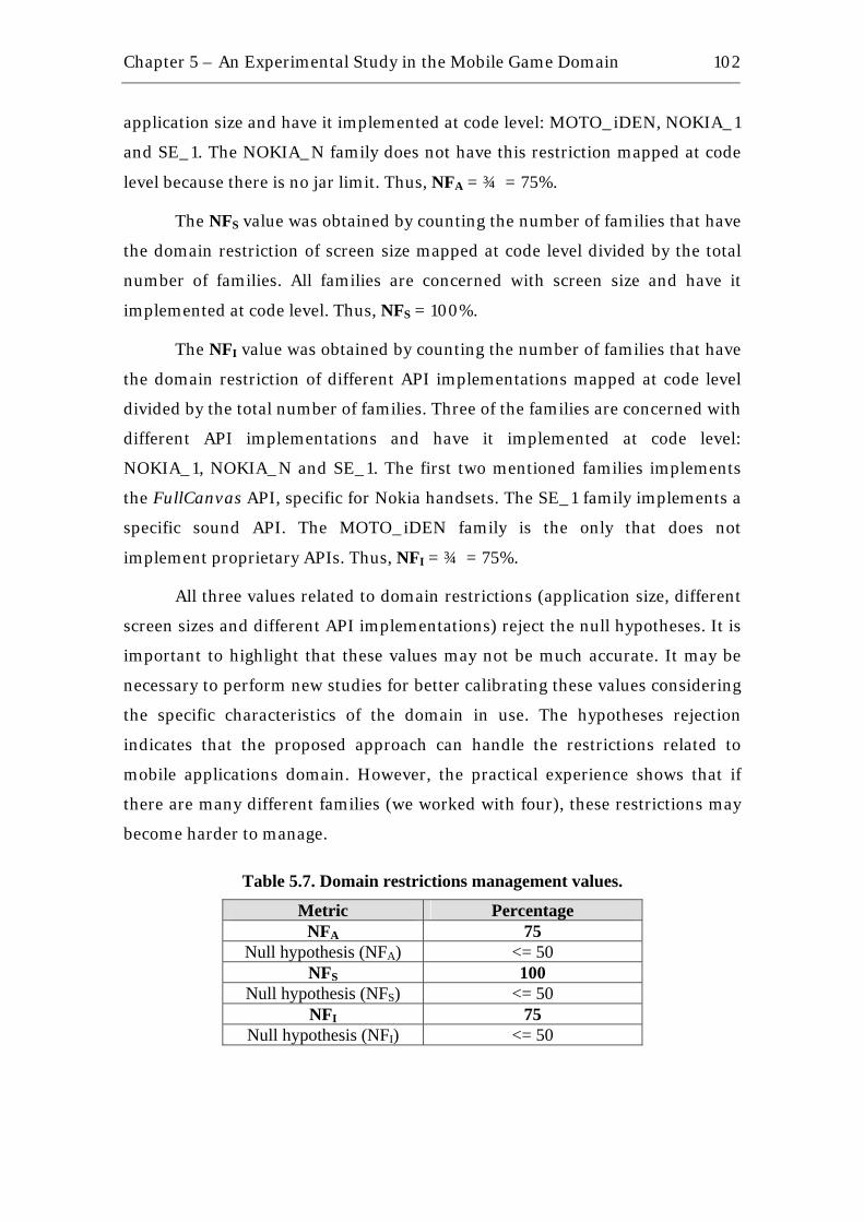
Chapter 5 – An Experimental Study in the Mobile Game Domain
102
application size and have it implemented at code level: MOTO_iDEN, NOKIA_1
and SE_1. The NOKIA_N family does not have this restriction mapped at code
level because there is no jar limit. Thus, NFA = ¾ = 75%.
The NFS value was obtained by counting the number of families that have
the domain restriction of screen size mapped at code level divided by the total
number of families. All families are concerned with screen size and have it
implemented at code level. Thus, NFS = 100%.
The NFI value was obtained by counting the number of families that have
the domain restriction of different API implementations mapped at code level
divided by the total number of families. Three of the families are concerned with
different API implementations and have it implemented at code level:
NOKIA_1, NOKIA_N and SE_1. The first two mentioned families implements
the FullCanvas API, specific for Nokia handsets. The SE_1 family implements a
specific sound API. The MOTO_iDEN family is the only that does not
implement proprietary APIs. Thus, NFI = ¾ = 75%.
All three values related to domain restrictions (application size, different
screen sizes and different API implementations) reject the null hypotheses. It is
important to highlight that these values may not be much accurate. It may be
necessary to perform new studies for better calibrating these values considering
the specific characteristics of the domain in use. The hypotheses rejection
indicates that the proposed approach can handle the restrictions related to
mobile applications domain. However, the practical experience shows that if
there are many different families (we worked with four), these restrictions may
become harder to manage.
Table 5.7. Domain restrictions management values.
Metric Percentage NFA 75
Null hypothesis (NFA) <= 50 NFS 100
Null hypothesis (NFS) <= 50 NFI 75
Null hypothesis (NFI) <= 50
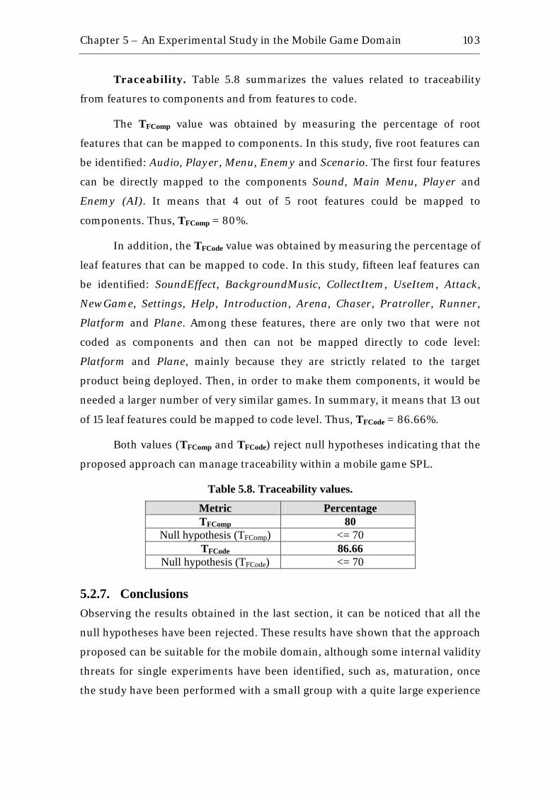
Chapter 5 – An Experimental Study in the Mobile Game Domain
103
Traceability. Table 5.8 summarizes the values related to traceability
from features to components and from features to code.
The TFComp value was obtained by measuring the percentage of root
features that can be mapped to components. In this study, five root features can
be identified: Audio, Player, Menu, Enemy and Scenario. The first four features
can be directly mapped to the components Sound, Main Menu, Player and
Enemy (AI). It means that 4 out of 5 root features could be mapped to
components. Thus, TFComp = 80%.
In addition, the TFCode value was obtained by measuring the percentage of
leaf features that can be mapped to code. In this study, fifteen leaf features can
be identified: SoundEffect, BackgroundMusic, CollectItem, UseItem, Attack,
NewGame, Settings, Help, Introduction, Arena, Chaser, Pratroller, Runner,
Platform and Plane. Among these features, there are only two that were not
coded as components and then can not be mapped directly to code level:
Platform and Plane, mainly because they are strictly related to the target
product being deployed. Then, in order to make them components, it would be
needed a larger number of very similar games. In summary, it means that 13 out
of 15 leaf features could be mapped to code level. Thus, TFCode = 86.66%.
Both values (TFComp and TFCode) reject null hypotheses indicating that the
proposed approach can manage traceability within a mobile game SPL.
Table 5.8. Traceability values.
Metric Percentage TFComp 80
Null hypothesis (TFComp) <= 70 TFCode 86.66
Null hypothesis (TFCode) <= 70
5.2.7. Conclusions Observing the results obtained in the last section, it can be noticed that all the
null hypotheses have been rejected. These results have shown that the approach
proposed can be suitable for the mobile domain, although some internal validity
threats for single experiments have been identified, such as, maturation, once
the study have been performed with a small group with a quite large experience

Chapter 5 – An Experimental Study in the Mobile Game Domain
104
in the mobile game domain. So, a new experiment in the same direction would
have difficulties to find such experienced staff.
In addition, comparing with other SPL processes mentioned in Chapter 3,
a higher level of details in the domain implementation step can help a lot on
generating low complexity components, handling domain restrictions, such as
the ones listed for the mobile game domain, and maintaining the artifacts
traceable from domain features to components code.
Moreover, considering the context of the mobile domain and its
peculiarities, it would be necessary to perform new studies to calibrate the value
of null hypothesis for the metrics related to domain restrictions management
and traceability.
5.2.8. The Lessons Learned One of the strongest points to be highlighted in this study is related to the
facility of applying conditional compilation tags in code, mainly when the
product map explicitly maintains all information about handsets capabilities
and their respective tags. On the other hand, the use of these tags can become
problematic if the number of product families grows too much. However, when
combined with refactoring tools such as FLiP (Calheiros et al., 2007), which
handles with aspect oriented techniques, the approach described by this work
can become really useful even with a big number of product families, mainly
because those kind of tools works better if code is early organized, so improving
the refactoring quality.
Furthermore, as a lesson learned from this project, it can be mentioned
that it is unavoidable the use of a tool to manage all conditional compilation
tags, mainly when the number of product families becomes high. The tool would
take as input the groups of conditional compilation tags as described in product
map and then deploy different products according to different families. The tool
should also be responsible for managing the dependencies between tags of
different product families, and so it would help on faster deployments.

Chapter 5 – An Experimental Study in the Mobile Game Domain
105
5.3. Chapter Summary This chapter presented an experimental study, following the organization
proposed by (Wohlin et al., 2000), in order to evaluate the approach described
in Chapter 4, which handles with core assets implementation in the mobile
game domain. The study has analyzed three different mobile games and
structured a software product line based on commonality and variability
analysis among these games, considering the specific characteristics of the
domain. The results of the study have shown that the approach can be suitable
for the mobile domain.
Next chapter presents the conclusions of this work and the directions for
future work.

6 Conclusions
“Science never solves a problem without creating ten more”
George Bernard Shaw (1856 – 1950) Nobel Prize in Literature (1925), Irish playwright
It has been about forty years since the term software engineering was first
coined in the late 1960s, and there software reuse principles were born. Through
all these years, many different approaches have been developed in order to
achieve the well known goals in the software world: high productivity, high
quality and low costs. These approaches include buzzwords such as component-
based development, domain engineering processes and software product lines
(SPL). As we mentioned in Chapter 2, software product lines are being explored
in different domains and contexts with many successful cases. Big companies,
such as Philips, Hewlett-Packard (HP), Boeing and Nokia, have proved their
successful experiences with software product lines in terms of market
leadership, constant growth in revenues and consequently great profits.
However, one particular market segment where the software product line
approach has not yet had many successful cases is the mobile game domain, in
spite of its high-growth in the last five years and the expectation of reaching the
mark of $6.1 billion in 2010. Industrial practitioners believe that mobile games
is the fastest growing “new” games sector. The main reason for this lack of
successful cases is related to the fact that the mobile game domain presents
specific characteristics, especially because of the big diversity of handsets and
the need of ubiquitous applications running in as many handsets as possible.

Chapter 6 – Conclusions
107
These characteristics can make the development and installation of a SPL
difficult.
Some efforts have been made to apply SPL approach to mobile game
domain. However, the current work in the SPL area, as we could see in Chapter
3, does not address properly the mentioned characteristics of the domain,
mainly in domain implementation phase.
In this work, we described a practical approach to develop core assets in a
SPL applied to the mobile game domain, providing details at code level, as
shown in Chapter 4, and then we performed an experimental study with three
mobile games following the mentioned approach, as can be seen in Chapter 5.
The results of the case study have shown that the approach can be suitable for
the mobile game domain.
6.1. Research Contributions The main contributions of this work remain on the aspects related to: the
presentation of a specific survey on the state-of-the-art in software product line
processes; the definition of an approach to implement core assets in a software
product line applied to the mobile game domain; the execution of an
experimental study which evaluated positively the early mentioned approach.
• A survey on the state-of-the-art in software product line
processes: complementing a survey by (Almeida, 2007), the Chapter 3
presents nine SPL processes, besides other seven relevant domain
engineering processes mentioned. The survey describes each process
taking into consideration mainly the aspects related to the domain
implementation phase.
• The definition of an approach to implement core assets in a
software product line applied to the mobile game domain: in
order to address properly the restrictions of the mobile domain, for
example, memory size, application size and processing power, Chapter 4
focus on the description of a practical approach to implement core assets
in the mobile game domain. The approach presents three phases:
component modeling, component implementation and component

Chapter 6 – Conclusions
108
testing. To ease the practical application of the approach, inputs, outputs,
roles and guidelines are defined.
• The execution of an experimental study: as a form of practical
evaluation of the approach proposed, an experimental study was
executed and presented positive results, showing that the proposed
approach can be feasible.
6.2. Related Work All the work described in Chapter 3, including component-based development,
domain engineering and software product line processes, can be applied on
different contexts, however, in the particular case of the mobile domain,
adaptations in the processes should be done to make them address properly the
restrictions of that domain. It happens mainly because some of the processes
are too general or handle with technologies that are not well established in the
mobile domain, such as OSGi (OSGi, 2008).
In this context, some efforts were made in order to adapt a defined SPL
process to mobile game domain, such as the GoPhone Project (Muthig et al.,
2004), an adaptation of PuLSE (Bayer et al., 1999) and KobrA (Atkinson et al.,
2000). This project establishes a SPL using four target handsets with a reduced
set of features (four features are described: send message, show message, start
chat and view and save calendar entry), but it does not provide details on how
to implement variability at the code level and also does not consider common
restrictions in the mobile domain, such as screen size and different API
implementations according to different vendors.
In addition, other related works define approaches (Alves et al., 2005a),
(Alves et al., 2005b), (Alves et al., 2006), (Matos, 2008) and refactoring tools
for extracting product lines from different versions of the same product, for
instance, FLiP tool (Calheiros et al., 2007). As a common practice in the mobile
applications domain is to adapt an application for different handsets (porting),
FLiP is intended to analyze the code of those different versions of the same
application and then it generates a product line based on aspect-oriented
programming, mapping the cross-cutting concerns into aspects (Kiczales et al.,
1997). In the case of mobile game domain, for example, a cross-cutting concern

Chapter 6 – Conclusions
109
can be screen size, because this characteristic of a handset affects different parts
of the code at different levels. This kind of tool, which handles cross-cutting
concerns, can be extremely useful when the product line is defined by a single
product and different versions of it must be implemented to support different
families of handsets, as the Abstraction Level 1 shown in Figure 6.1..
Figure 6.1. Abstraction levels in software product lines applied to mobile game domain.
However, not only is our approach intended to consider the different
versions of the same product as potential variabilities to be used in other
products, but it addresses the variability and commonality of different products
in the same domain at a higher level of abstraction, as Abstraction Level 2
shown in Figure 6.1..
In addition, our approach does not exclude the possibility of using a tool
like FLiP. As we said before, this kind of tool is based on code refactoring and
generates as output aspects in AspectJ syntax (AspectJ, 2008), which can
improve code maintainability, readability and cohesion and reduce coupling.
For better usage of the tool, it is highly recommended to provide as input a
quality code, improving chances of successful refactoring steps. In this context,
our approach can be used to provide such quality code, as we directly focus on
the domain implementation phase of a SPL, defining clear steps, inputs,

Chapter 6 – Conclusions
110
outputs, roles and guidelines. So, our proposal in this work and a tool like FLiP
can complement each other to implement a mobile game product line.
6.3. Future Work Due to the time constraints imposed on a M.Sc. dissertation, this work can be
seen as an initial endeavor towards the full vision of a software product line
process tailored to the mobile game domain. Thus, the following issues should
be investigated as future work:
• Application of the approach in an industrial context. We are
planning to apply the approach described in this work in an industrial
context and evaluate the benefits in a game development project
composed of 8 people, including 4 developers, 3 graphical designers and
1 game designer. The team has previous experience in 3D mobile games
and had already developed two different games in the same domain.
Then the approach is going to be applied to produce a third game, using
3D capabilities and reusing the artifacts already produced by the team.
The greatest motivation for this future work involves the establishment of
a SPL for mobile 3D games, which are becoming the most popular type of
game in mobile domain because of its delightful visual effects, and then
new games could be rapidly deployed with quality.
• Tool support. During the execution of the experimental study, we
identified the need of a tool to manage the conditional compilation tags
in order to ease the deployment of new products. The tool would take as
input the set of possible conditional compilation tags for a specific family
of handsets and their respective dependencies and generate automatically
the different application builds. One possible future work can be the
development of such tool, and next, the use of it to reevaluate of the
approach described by this work adding a bigger number of target
handsets.
• Automatic selection of variability implementation techniques.
Another possible future work can involve the adaptation of the domain
implementation step to allow automatic selection of the variability
implementation technique to be used. For example, if a given product
Chapter 6 – Conclusions
111
needs to be deployed for some target handsets and they are not much
restrictive considering their hardware capabilities, the inheritance and
parameterization techniques may be explored. On the other hand, if the
target handsets have many restrictions, then only conditional
compilation should be explored. In order to make possible such
automatic variability technique selection, an extra effort has to be done to
adapt the domain implementation process, as well as it would be also
necessary to involve the use of a tool to allow the domain architect
selecting among the existent techniques and the correspondent biding
time for each feature in the domain.
• Application engineering. The approach proposed by this work is
mainly focused on core assets implementation in order to establish the
basic structure of a SPL. In this context, extending the approach to
handle the details related to application engineering phase in a SPL can
be a possible future work.
• Experimental Study. This dissertation presented the definition,
planning, operation, analysis and interpretation of an experimental
study. However, new studies in different contexts are still necessary,
including more subjects, qualitative analysis, in order to evaluate the
difficulty of applying the proposed approach, and other types of games,
such as 3D games. Those new studies would calibrate the proposed
approach and the experimental plan.
6.4. Academic Contributions The knowledge developed during this work resulted in the following
publication:
• (Nascimento et al., 2006) L. M. Nascimento, E. S. Almeida, S. R. L.
Meira, Component-Based Development in J2ME: A Framework
for Graphical Interface Development in Mobile Devices, 6th
Brazilian Workshop on Component-Based Development (WDBC'2006),
Recife, Brazil, December, 2006, pp. 88-95.
Chapter 6 – Conclusions
112
• (Nascimento et al., 2008a) L. M. Nascimento, E. S. Almeida, S. R. L.
Meira, A Case Study in Software Product Lines - The Case of the
Mobile Game Domain, 34th IEEE EUROMICRO Conference on
Software Engineering and Advanced Applications (SEAA), Component-
Based Software Engineering (CBSE) Track, Parma, Italy, September,
2008.
Furthermore, the co-participations on the following publications
contributed for acquiring experience and knowledge in the software reuse area:
• (Almeida et al., 2007a) E. S. Almeida, A. Alvaro, V. C. Garcia, J. C. C. P.
Mascena, V. A. A. Burégio, L. M. Nascimento, D. Lucrédio, S. R. L. Meira,
C.R.U.I.S.E: Component Reuse in Software Engineering,
C.E.S.A.R e-book, Available on http://cruise.cesar.org.br/, Brazil, 2007,
pp. 219.
• (Almeida et al., 2007b) E. S. Almeida, A. Álvaro, V. C. Garcia, L. M.
Nascimento, S. R. L. Meira, D. Lucrédio, A Systematic Approach to
Design Domain-Specific Software Architectures, Journal of
Software (JSW), Vol. 02, No. 02, August, 2007, pp. 38-51.
• (Almeida et al., 2007c) E. S. Almeida, A. Alvaro, V. C. Garcia, L. M.
Nascimento, D. Lucrédio, S. R. L. Meira, Designing Domain-Specific
Software Architecture: Towards a New Approach, 6th Working
IEEE/IFIP Conference on Software Architecture (WICSA), Mumbai,
India, January, 2007, pp. 30-33.
• (Lisboa et al., 2008) L. B. Lisboa, L. M. Nascimento, E. S. Almeida, S. R.
L. Meira, A Case Study in Software Product Lines: An
Educational Experience, 21st IEEE Conference on Software
Engineering Education and Training (CSEE&T '08), Charleston, South
Carolina, USA, April, 2008, pp. 155-162.
Besides these published papers, there are two papers in evaluation:
(Nascimento et al., 2008b) and (Nascimento et al., 2009).

Chapter 6 – Conclusions
113
6.5. Concluding Remarks Software product lines have been revealed as a good form to achieve the so
desired software engineering tripod: high productivity, high quality and low
costs. Several successful cases of software product lines can be found in
different contexts and domains. However, few examples can be found in the
mobile game domain, mainly because of the domain restrictions, such as
reduced memory available, small processing power and limited application size.
This work contributed to establish a practical approach for core assets
implementation in the mobile game domain.
It is believed that the mobile applications domain is still in chaos. The
handsets are produced with many different operating systems, different screen
sizes, different memory sizes, different processors, proprietary API
implementations, different implementations of the same API specification,
different keypads, many different optional features, such as camera, Bluetooth,
mp3 players, and so on. A couple of decades ago, the environment of personal
computers was exactly like that – a kind of chaos – and the evolution took place
in many directions of research, including hardware and software, enabling the
technology we can see nowadays. It is possible that the same thing happens to
the mobile domain, reducing the effort when developing software for the mobile
platform because there will be much less variabilities to be handled at code
level. Until that does not happen, approaches like the one described in this
dissertation will have to be used to make possible the so mentioned phrase:
“write once run everywhere”. We believe this work is a step forward in this long
journey involving the mobile domain.

References
“No man was ever wise by chance” Lucius Annaeus Seneca (4 BC – AD 65)
Roman philosopher, statesman and dramatist
(Almeida et al., 2004) E. S. Almeida, A. Alvaro, D. Lucrédio, V. C. Garcia, S. R.
L. Meira, RiSE Project: Towards a Robust Framework for
Software Reuse, IEEE International Conference on Information
Reuse and Integration (IRI), Las Vegas, Nevada, USA, November,
2004, pp. 48-53.
(Almeida et al., 2005) E. S. Almeida, A. Alvaro, D. Lucrédio, V. C. Garcia, S. R.
L. Meira, A Survey on Software Reuse Processes, IEEE
Internacional Conference on Information Reuse and Integration (IRI),
Las Vegas, Nevada, USA, August, 2005, pp. 66-71.
(Almeida, 2007) E. S. Almeida, RiDE: The RiSE Process for Domain
Engineering, Ph.D. Thesis, Federal University of Pernambuco,
Informatics Center, Brazil, March, 2007, pp. 276.
(Almeida et al., 2007a) E. S. Almeida, A. Alvaro, V. C. Garcia, J. C. C. P.
Mascena, V. A. A. Burégio, L. M. Nascimento, D. Lucrédio, S. R. L.
Meira, C.R.U.I.S.E: Component Reuse in Software
Engineering, C.E.S.A.R e-book, Available on
http://cruise.cesar.org.br/, Brazil, 2007, pp. 219.
(Almeida et al., 2007b) E. S. Almeida, A. Álvaro, V. C. Garcia, L. M. Nascimento,
S. R. L. Meira, D. Lucrédio, A Systematic Approach to Design
Domain-Specific Software Architectures, Journal of Software
(JSW), Vol. 02, No. 02, August, 2007, pp. 38-51.
References 115
(Almeida et al., 2007c) E. S. Almeida, A. Alvaro, V. C. Garcia, L. M. Nascimento,
D. Lucrédio, S. R. L. Meira, Designing Domain-Specific Software
Architecture: Towards a New Approach, 6th Working IEEE/IFIP
Conference on Software Architecture (WICSA), Mumbai, India,
January, 2007, pp. 30-33.
(Almeida et al., 2008) E. S. Almeida, E. C. R. Santos, A. Alvaro, V. C. Garcia, D.
Lucrédio, R. P. M. Fortes, S. R. L. Meira, Domain Implementation
in Software Product Lines Using OSGi, 7th International
Conference on Composition-Based Software Systems (ICCBSS),
Madrid, Spain, February, 2008, pp. 72-81.
(Alvaro et al., 2007) A. Alvaro, E. S. Almeida, S. R. L. Meira, Component
Quality Assurance: Towards a Software Component
Certification Process, IEEE Internacional Conference on
Information Reuse and Integration (IRI), Las Vegas, Nevada, USA,
August 2007, pp. 134-139.
(Alves et al., 2005a) V. Alves, I. Cardim, H. Vital, P. Sampaio, A. Damasceno, P.
Borba, G. Ramalho, Comparative Analysis of Porting Strategies
in J2ME Games, 21st IEEE International Conference on Software
Maintenance (ICSM’05), Budapest, Hungary, September, 2005, pp.
123-132.
(Alves et al., 2005b) V. Alves, P. Matos, L. Cole, P. Borba, G. Ramalho,
Extracting and Evolving Mobile Games Product Lines, 9th
International Software Product Line Conference (SPLC'05), Rennes,
France, September, 2005, pp. 70-81.
(Alves et al., 2006) V. Alves, A. Costa Neto, S. Soares, G. Santos, F. Calheiros, V.
Nepomuceno, D. Pires, J. Leal, P. Borba, From Conditional
Compilation to Aspects: A Case Study in Software Product
Lines Migration, Aspect-Oriented Product Line Engineering
(AOPLE'06), Workshop of the 5th International Conference on
Generative Programming and Component Engineering (GPCE'06),
Portland, Oregon, USA, October, 2006, pp. 46-52.
References 116
(America et al., 2000) P. America, H. Obbink, R. V. Ommering, F. V. D. Linden,
CoPAM: A Component-Oriented Platform Architecting
Method Family for Product Family Engineering, 1st Software
Product Line Conference (SPLC1), Denver, Colorado, USA, August,
2000, pp. 15.
(Anastasopoulos & Gacek, 2001) M. Anastasopoulos, C. Gacek, Implementing
Product Line Variabilities, Symposium on Software Reusability
(SSR'01), Toronto, Ontario, Canada, May, 2001, pp. 109-117.
(Aoyama et al., 2001) M. Aoyama, G. T. Heineman, B. Councill. Component-
Based Software Engineering: Putting the Pieces Together,
Addison-Wesley, 2001, pp. 818.
(AspectJ, 2008) The AspectJ Project, Available on http://www.eclipse.org/
aspectj/, Accessed in January, 2008.
(Atkinson et al., 2000) C. Atkinson, J. Bayer, D. Muthig, Component-Based
Product Line Development: The KobrA Approach, 1st Software
Product Line Conference (SPLC1), Denver, Colorado, USA, August,
2000, pp.19.
(Basili et al., 1986) V. R. Basili, R. W. Selby, D. H. Hutchins, Experimentation
in Software Engineering, IEEE Transactions on Software
Engineering, Vol. 12, No. 07, July, 1986, pp. 733-743.
(Basili et al., 1994) V. R. Basili, G. Caldiera, H. D. Rombach, The Goal
Question Metric Approach, Encyclopedia of Software Engineering,
Vol. 02, September, 1994, pp. 528-532.
(Basili et al., 1995) V. R. Basili, M. Zelkowitz, F. McGARRY, J. Page, S. Waligora,
R. Pajerski, SEL’s Software Process Improvement Program,
IEEE Software, Vol. 12, No. 06, November, 1995, pp. 83-87.
(Basili, 1996) V. R. Basili, The Role of Experimentation in Software
Engineering: Past, Present, and Future, 18th International
Conference on Software Engineering (ICSE), Berlin, Germany, March,
1996, pp. 442-449.
References 117
(Basili et al., 1996) V. R. Basili, L. C. Briand, W. L. Melo, How reuse
influences productivity in object-oriented systems,
Communications of the ACM, Vol. 39, No. 10, October, 1996, pp. 104-
116.
(Batory & O’Malley, 1992) D. Batory, S. O’Malley, The Design and
Implementation of Hierarchical Software Systems with
Reusable Components, ACM Transactions on Software
Engineering and Methodology (TOSEM), Vol. 01, No. 04, October,
1992, pp. 355-398.
(Batory et al., 2000) D. Batory, R. Cardone, Y. Smaragdakis, Object-oriented
frameworks and product lines, 1st Software Product Line
Conference (SPLC1), Denver, Colorado, USA, August, 2000, pp. 227-
248.
(Batory et al., 2002) D. Batory, C. Johnson, B. MacDonald, D. von Heeder,
Achieving extensibility through product-lines and domain-
specific languages: a case study, ACM Transactions on Software
Engineering and Methodology (TOSEM), Vol. 11, No. 02, April, 2002,
pp. 191-214.
(Bayer et al., 1999) J. Bayer, O. Flege, P. Knauber, R. Laqua, D. Muthig, K.
Schmid, T. Widen, J. DeBaud, PuLSE: A Methodology to Develop
Software Product Lines, Symposium on Software Reusability
(SSR'99), Los Angeles, California, USA, May, 1999, pp. 122-131.
(Beck, 1999) K. Beck, Extreme Programming Explained: Embrace
Change, Addison-Wesley, 1999, pp. 224.
(Bergey et al., 1998) J. Bergey, DoD Product Line Practice Workshop
Report, Technical Report CMU/SEI-98-TR-07, Carnegie Mellon, May,
1998.
(Boehm et al., 2005) B. W. Boehm, H. D. Rombach, M. V. Zelkowitz,
Foundations of Empirical Software Engineering: The Legacy
of Victor R. Basili, Springer, 2005, pp. 431.
(Boeing, 2008) The Boeing Company Website, Available on
http://www.boeing.com/, Accessed in January, 2008.

References 118
(Bosch, 2002) J. Bosch, Maturity and Evolution in Software Product
Lines: Approaches, Artefacts and Organization, 2nd Software
Product Line Conference (SPLC2), San Diego, California, August, 2002,
pp. 257-271.
(Bosch, 2004) J. Bosch, On the Development of Software Product-
Family Components, 3rd Software Product Line Conference
(SPLC’04), Boston, Massachusetts, USA, August, 2004, pp. 146-164.
(Bunse & Atkinson, 1999) C. Bunse, C. Atkinson, The Normal Object Form:
Bridging the Gap from Models to Code, 2nd International
Conference on the Unified Modeling Language (UML'99), Fort Collins,
Colorado, USA, October, 1999, pp. 753.
(Calheiros et al., 2007) F. Calheiros, P. Borba, S. Soares, V. Nepomuceno, V.
Alves, Product line variability refactoring tool, 1st Workshop on
Refactoring Tools (WRT'07), in conjunction with the 21st European
Conference on Object-Oriented Programming (ECOOP'07), Berlin,
Germany, July, 2007, pp. 33-34.
(Cheesman & Daniels, 2001) J. Cheesman, J. Daniels, UML Components: A
Simple Process for Specifying Component-Based Software,
Addison-Wesley, 2001, pp. 208.
(Clements & Northrop, 2001) P. Clements, L. Northrop, Software Product
Lines: Practices and Patterns, Addison-Wesley, 2001, pp. 608.
(Coplien, 1998) J. Coplien, Multi-Paradigm Design for C++, Addison-
Wesley, 1998, pp. 304.
(Cox, 1990) B. J. Cox, Planning the Software Industrial Revolution, IEEE
Software, Vol. 07, No. 06, November, 1990, pp. 25-33.
(Czarnecki & Eisenecker, 2000) K. Czarnecki, U. W. Eisenecker, Generative
Programming: Methods, Tools, and Applications, Addison-
Wesley, 2000, pp. 832.
(Davis, 1987) S. M. Davis, Future Perfect, Addison-Wesley, 1987, pp. 272.
(Doerr & Sharp, 2000) B. S. Doerr, D. C. Sharp, Freeing Product Line
Architectures from Execution Dependencies, 1st Software

References 119
Product Line Conference (SPLC1), Denver, Colorado, USA, August,
2000, pp. 313–329.
(D'Souza & Wills, 2001) D. D'Souza, A. C. Wills, Objects, Components, and
Frameworks with UML - The Catalysis Approach, Addison-
Wesley, 2001. pp. 816.
(Ezran et al., 2002) M. Ezran, M. Morisio, C. Tully, Practical Software
Reuse, Springer, 2002, pp. 374.
(Fayad, 1997) M. E. Fayad, Software Development Process: A Necessary
Evil, Communications of the ACM, Vol. 40, No. 09, September, 1997,
pp. 101-103.
(Filho et al., 2008) E. D. S. Filho, R. O. Cavalcanti, D. F. S. Neiva, T. H. B.
Oliveira, L. B. Lisboa, E. S. Almeida, S. R. L. Meira, Evaluating
Domain Design Approaches Using Systematic Review, 2nd
European Conference on Software Architecture (ECSA), Lecture Notes
in Computer Science (LNCS), Springer Verlag, Cyprus, September,
2008.
(Flood, 2003) K. Flood, Game Unified Process (GUP), Gamedev Article,
2003, Available on http://www.gamedev.net/reference/articles/
article1940.asp, Accessed in January, 2008.
(Flynt & Salem, 2005) J. P. Flynt, O. Salem, Software Engineering for
Game Developers, Course Technology PTR, 2005, pp. 904.
(Foreman, 1996) J. Foreman, Product Line Based Software Development
- Significant Results, Future Challenges, 8th Software
Technology Conference (STC’96), Salt Lake City, Utah, April, 1996.
(Frakes & Succi, 2001) W. B. Frakes, G. Succi, An Industrial Study of
Reuse, Quality, and Productivity, Journal of System and Software
(JSS), Vol. 57, No. 02, June, 2001, pp. 99-106.
(Furtado, 2006) A. W. B. Furtado, SharpLudus: Improving Game
Development Experience through Software Factories and
Domain-Specific Languages, M.Sc. Dissertation, Federal

References 120
University of Pernambuco, Informatics Center, Brazil, April, 2006, pp.
137.
(Gamma et al., 1995) E. Gamma, R. Helm, R. Johnson, J. Vlissides, Design
Patterns: Elements of Reusable Object-Oriented Software,
Addison-Wesley, 1995, pp. 395.
(Garcia et al., 2008a) V. C. Garcia, L. B. Lisboa, F. A. Durão, E. S. Almeida, S. R.
L. Meira, Lightweight Technology Change Management
Approach to Facilitating Reuse Adoption, 2nd Brazilian
Symposium on Software Components, Architectures, and Reuse
(SBCARS), Porto Alegre, Brazil, August, 2008.
(Garcia et al., 2008b) V. C. Garcia, L. B. Lisboa, S. R. L. Meira, E. S. Almeida, D.
Lucrédio, R. P. M. Fortes, Towards an Assessment Method for
Software Reuse Capability, 8th International Conference on
Quality Software (QSIC), Oxford, UK, August, 2008.
(Glass & DeMarco, 2006) B. Glass, T. Demarco, Software Creativity 2.0,
developer.* Books, 2006, pp. 484.
(Gomaa, 2005) H. Gomaa, Designing Software Product Lines with UML:
From Use Cases to Pattern-Based Software Architectures,
Addison-Wesley, 2005, pp. 701.
(Greenfield et al., 2004) J. Greenfield, K. Short, S. Cook, S. Kent, J. Crupi,
Software Factories: Assembling Applications with Patterns,
Models, Frameworks, and Tools, Wiley & Sons, 2004, pp. 500.
(Griss, 1994) M. L. Griss, Software Reuse Experience at Hewlett-
Packard, 16th IEEE International Conference on Software
Engineering (ICSE), Sorrento, Italy, May, 1994, pp. 270.
(Griss, 1995) M. L. Griss, Making Software Reuse Work at Hewlett-
Packard, IEEE Software, Vol. 12, No. 01, January, 1995, pp. 105-107.
(Griss et al., 1998) M. L. Griss, J. Favaro, M. d' Alessandro, Integrating
Feature Modeling with the RSEB, 5th International Conference on
Software Reuse (ICSR), Victoria, Canada, June, 1998, pp. 76-85.
References 121
(Heie, 2002) A. Heie, Global Software Product Lines and Infinite
Diversity, Keynote speech in the 2nd Software Product Line
Conference (SPLC2), San Diego, California, August, 2002. Available on
http://www.sei.cmu.edu/SPLC2/keynote_slides/keynote_1.htm, Acce-
ssed in April 2008.
(HP, 2008) The Hewlett-Packard Website, Available on
http://www.hp.com/, Accessed in January, 2008.
(IEEE Std, 1990) IEEE, IEEE Standard Glossary of Software
Engineering Terminology, IEEE Std 610.12-1990, 1990.
(Jacobson et al., 1997) I. Jacobson, M. L. Griss, P. Jonsson, Making the Reuse
Business Work, IEEE Computer, Vol. 30, No. 10, October, 1997, pp.
36-42.
(Jacobson et al., 1999) I. Jacobson, G. Booch, J. Rumbaugh, The Unified
Software Development Process, Addison-Wesley, 1999, pp. 463.
(Java ME, 2008) Java ME - The Most Ubiquitous Application Platform
for Mobile Devices, Available on http://java.sun.com/javame/
index.jsp. Accessed in May, 2008.
(Jezequel & Meyer, 1997) J. M. Jezequel, B. Meyer, Design by Contract: The
Lessons of Ariane, IEEE Computer, Vol. 30, No. 01, January, 1997,
pp. 129-130.
(Johnson & Foote, 1988) R. Johnson, B. Foote, Designing Reusable Classes,
Journal of Object-Oriented Programming, Vol. 01, No. 02, June/July,
1988, pp. 22-35.
(JSR-232, 2008) JSR-232, Java Specification Request 232 - Mobile
Operational Management, Available on http://www.jcp.org/en/jsr/
detail?id=232, Accessed in January, 2008.
(Kang et al., 1990) K. C. Kang, S. G. Cohen, J. A. Hess, W. E. Novak, A. S.
Peterson, Feature-Oriented Domain Analysis (FODA)
Feasibility Study, Technical Report CMU/SEI-90-TR-021, Carnegie
Mellon, November, 1990.

References 122
(Kang et al., 1998) K. C. Kang, S. Kim, J. Lee, K. Kim, E. Shin, M. Huh, FORM:
A Feature-Oriented Reuse Method with domain-specific
reference architectures, Annals of Software Engineering Notes,
Vol. 05, No. 00, January, 1998, pp. 143-168.
(Kang et al., 2002) K. C. Kang, J. Lee, P. Donohoe, Feature-Oriented
Product Line Engineering, IEEE Software, Vol. 19, No. 04,
July/August, 2002, pp.58-65.
(Kiczales et al., 1997) G. Kiczales, J. Lamping, A. Mendhekar, C. Maeda, C.
Videira Lopes, J. M. Loingtier, J. Irwin, Aspect-Oriented
Programming, 11th European Conference on Object-Oriented
Programming (ECOOP’97), Jyväskylä, Finland, June, 1997, pp. 220-
242.
(Kim & Chang, 2004) S. D. Kim, S. H. Chang, A Systematic Method to
Identify Software Components, 11th Asia-Pacific Software
Engineering Conference (APSEC’04), Seoul, South Korea, December,
2004, pp. 92-98.
(Krueger, 1992) C. W. Krueger, Software Reuse, ACM Computing Surveys,
Vol. 24, No. 02, June, 1992, pp. 131-183.
(Lim, 1994) W. C. Lim, Effects of Reuse on Quality, Productivity, and
Economics, IEEE Software, Vol. 11, No. 05, September, 1994, pp. 23-
30.
(Lisboa et al., 2007) L. B. Lisboa, V. C. Garcia, E. S. Almeida, S. R. L. Meira,
ToolDAy - A Process-Centered Domain Analysis Tool, 21st
Brazilian Symposium on Software Engineering (SBES), Tools Session,
João Pessoa, Brazil, October, 2007.
(Lisboa et al., 2008) L. B. Lisboa, L. M. Nascimento, E. S. Almeida, S. R. L.
Meira, A Case Study in Software Product Lines: An
Educational Experience, 21st IEEE Conference on Software
Engineering Education and Training (CSEE&T '08), Charleston, South
Carolina, USA, April, 2008, pp. 155-162.
(Martins et al., 2008) A. C. Martins, V. C. Garcia, E. S. Almeida, S. R. L. Meira,
Enhancing Components Search in a Reuse Environment

References 123
Using Discovered Knowledge Techniques, 2nd Brazilian
Symposium on Software Components, Architectures, and Reuse
(SBCARS), Porto Alegre, Brazil, August, 2008.
(Mascena et al., 2005) J. C. C. P. Mascena, E. S. Almeida, S. R. L. Meira, A
Comparative Study on Software Reuse Metrics and Economic
Models from a Traceability Perspective, IEEE Internacional
Conference on Information Reuse and Integration (IRI), Las Vegas,
Nevada, USA, August, 2005, pp. 72-77.
(Matos, 2008) P. O. A. Matos Junior, Analysis of Techniques for
Implementing Software Product Lines Variabilities, M.Sc.
Dissertation, Federal University of Pernambuco, Informatics Center,
Brazil, August, 2008, pp. 121.
(McCabe, 1976) T. J. McCabe, A Complexity Measure, IEEE Transactions on
Software Engineering, Vol. 02, No. 04, December, 1976, pp. 308-320.
(McConnell, 1998) S. McConnell, The Power of Process, IEEE Computer,
Vol. 31, No. 05, May, 1998, pp. 100-102.
(McGregor et al., 2002) J. D. McGregor, S. Jarrad, L. M. Northrop, and K. Pohl,
Initiating Software Product Lines, IEEE Software, Vol. 19, No.
04, July 2002, pp. 24–27.
(McIlroy, 1968) M. D. McIlroy, Mass Produced Software Components,
NATO Software Engineering Conference Report, Garmisch, Germany,
October, 1968, pp. 79-85.
(Mernik et al., 2005) M. Mernik, J. Heering, A. M. Sloane, When and How to
Develop Domain-Specific Languages, ACM Computing Surveys,
Vol. 37, No. 04, December, 2005, pp. 316-344.
(Mili et al., 1995) H. Mili, F. Mili, A. Mili, Reusing Software: Issues and
Research Directions, IEEE Transactions on Software Engineering,
Vol. 21, No. 06, June, 1995, pp. 528-562.
(Moore, 2001) M. Moore, Software Reuse: Silver Bullet?, IEEE Software,
Vol. 18, No. 05, September/October, 2001, pp. 86.
References 124
(Morisio et al., 2002) M. Morisio, M. Ezran, C. Tully, Success and Failure
Factors in Software Reuse, IEEE Transactions on Software
Engineering, Vol. 28, No. 04, April, 2002, pp. 340-357.
(Muthig et al., 2004) D. Muthig, I. John, M. Anastasopoulos, T. Forster, J.
Doerr, K. Schmid, GoPhone - A software product line in the
mobile phone domain, Technical Report, 025.04/E. Kaiserslautern,
Fraunhofer IESE, 2004.
(Nascimento et al., 2006) L. M. Nascimento, E. S. Almeida, S. R. L. Meira,
Component-Based Development in J2ME: A Framework for
Graphical Interface Development in Mobile Devices, 6th
Brazilian Workshop on Component-Based Development
(WDBC'2006), Recife, Brazil, December, 2006, pp. 88-95.
(Nascimento et al., 2008a) L. M. Nascimento, E. S. Almeida, S. R. L. Meira, A
Case Study in Software Product Lines - The Case of the
Mobile Game Domain, 34th IEEE EUROMICRO Conference on
Software Engineering and Advanced Applications (SEAA),
Component-Based Software Engineering (CBSE) Track, Parma, Italy,
September, 2008.
(Nascimento et al., 2008b) L. M. Nascimento, E. S. Almeida, S. R. L. Meira, A
Practical Approach for Core Assets Development in Software
Product Lines for the Mobile Game Domain and its Empirical
Validation, Software – Practice & Experience, Vol. 38, No. 12,
December, 2008, in evaluation.
(Nascimento et al., 2009) L. M. Nascimento, E. S. Almeida, S. R. L. Meira, Core
Assets Development in Software Product Lines - Towards a
Practical Approach for the Mobile Game Domain, 24th Annual
ACM Symposium on Applied Computing, Honolulu, Hawaii, USA,
March, 2009, in evaluation.
(Neighbors, 1980) J. M. Neighbors, Software Construction Using
Components, Ph.D. Thesis, University of California, Irvine,
Department of Information and Computer Science, USA, April, 1980,
pp.217.

References 125
(Nobrega et al., 2008) J. P. Nobrega, E. S. Almeida, S. R. L. Meira, InCoME:
Integrated Cost Model for Product Line Engineering, 34th IEEE
EUROMICRO Conference on Software Engineering and Advanced
Applications (SEAA), Component-Based Software Engineering (CBSE)
Track, Parma, Italy, September, 2008.
(Nokia, 2008) The Nokia Website, Available on http://www.nokia.com/,
Accessed in January, 2008.
(OMG UML, 2007) Object Management Group. OMG Unified Modelling
Language Specification, Available on http://www.uml.org/, Version
2.1.1, Accessed in September, 2007.
(OMG OCL, 2007) Object Management Group. OMG Object Constraint
Language (OCL), Available on http://www.omg.org/technology/
documents/modeling_spec_catalog.htm#OCL, Version 2.0, Accessed
in September, 2007.
(Ommering, 2000) R. V. Ommering, Beyond product families: Building a
product population, 3rd International Workshop on Software
Architectures for Product Families (IW-SAPF), Las Palmas de Gran
Canaria, Spain, March, 2000, pp. 187-198.
(Ommering et al., 2000) R. van Ommering, F. van der Linden, J. Kramer, and J.
Magee, The Koala Component Model for Consumer
Electronics Software, IEEE Computer, Vol. 33, No. 03, March,
2000, pp. 78–85.
(Ommering, 2002) R. van Ommering, Building Product Populations with
Software Components, 24th International Conference on Software
Engineering (ICSE), Orlando, Florida, USA, May, 2002, pp. 255–265.
(Ommering, 2004) R. van Ommering, Building Product Populations with
Software Components, Ph.D. Thesis, University of Groningen,
Netherlands, 2004.
(OSGi, 2008) OSGi Alliance, Available on http://www.osgi.org. Accessed in
February, 2008.

References 126
(Parnas, 1978) D. Parnas, Designing Software for Ease of Extension and
Contraction, 3rd International Conference on Software Engineering
(ICSE), Atlanta, Georgia, USA, May, 1978, pp. 264-277.
(Pasetti & Pree, 2000) A. Pasetti, W. Pree, Two Novel Concepts for
Systematic Product Line Development, 1st Software Product Line
Conference (SPLC1), Denver, Colorado, USA, August, 2000, pp. 249-
270.
(Philips, 2008) The Philips Website, Available on http://www.philips.com/,
Accessed in January, 2008.
(Pohl et al., 2005) K. Pohl, G. Bockle, F. van der Linden, Software Product
Line Engineering: Foundations, Principles and Techniques,
Springer, 2005, pp. 468.
(Poulin, 2006) J. S. Poulin, The Business Case for Software Reuse:
Reuse Metrics, Economic Models, Organizational Issues, and
Case Studies, Tutorial Notes, Torino, Italy, June, 2006.
(Pressman, 2005) R. S. Pressman, Software Engineering: A Practitioner’s
Approach, McGraw-Hill, 2005, pp. 880.
(Prieto-Diaz & Freeman, 1987) R. Prieto-Diaz, P. Freeman, Classifying
Software for Reusability, IEEE Software, Vol. 04, No. 01, January,
1987, pp. 06-16.
(Rombach, 2000) D. Rombach, Fraunhofer: The German Model for
Applied Research and Technology Transfer, 22nd International
Conference on Software Engineering (ICSE), Limerick, Ireland, May,
2000, pp. 25-34.
(Rozum, 1993) J. Rozum, Concepts on Measuring the Benefits of
Software Process Improvement, Technical Report CMU/SEI-93-
TR-009, Carnegie Mellon, June, 1993.
(Rucker, 2002) R. Rucker, Software Engineering and Computer Games,
Addison-Wesley, 2002, pp. 648.
(Sametinger, 1997) J. Sametinger, Software Engineering with Reusable
Components, Springer- Verlag, 1997, pp.275.

References 127
(SEI, 1997) Software Engineering Institute (SEI) / Carnegie Mellon,
Available on http://www.sei.cmu.edu/str/descriptions/
cyclomatic_body.html, Accessed in September, 2008.
(SEI, 2008) Software Engineering Institute (SEI) / Carnegie Mellon,
Available on http://www.sei.cmu.edu/, Accessed in January, 2008.
(Sharp, 2000) D. C. Sharp, Component Based Product Line
Development of Avionics Software, 1st Software Product Line
Conference (SPLC1), Denver, Colorado, USA, August, 2000, pp. 353–
369.
(Silva et al., 2008) F. R. C. Silva, E. S. Almeida, S. R. L. Meira, Towards an
Effective Component Testing Approach Supported by a CASE
Tool, 2nd Brazilian Symposium on Software Components,
Architectures, and Reuse (SBCARS), Porto Alegre, Brazil, August,
2008.
(Simos et al., 1996) M. Simos, D. Creps, C. Klingler, L. Levine, D. Allemang,
Organization Domain Modeling (ODM) Guideboo, Version 2.0,
Technical Report, June, 1996, pp. 509.
(SPL Hall of Fame, 2008) Software Product Line Hall of Fame, Available
on http://www.sei.cmu.edu/productlines/plp_hof.html, Accessed in
January, 2008.
(Szyperski, 2002) C. Szyperski, Component Software: Beyond Object-
Oriented Programming, Addison-Wesley, 2002, pp. 588.
(Toft et al., 2000) P. Toft, D. Coleman, J. Ohta, A Cooperative Model for
Cross-Divisional Product Development for a Software
Product Line, 1st Software Product Line Conference (SPLC1), Denver,
Colorado, USA, August, 2000, pp. 111-132.
(Villela, 2000) R. M. M. B. Villela, Search and Recovery of Components in
Software Reuse Environments (in portuguese), Ph.D. Thesis,
Federal University of Rio de Janeiro, December, 2000, pp. 264.
References 128
(Voget & Becker, 2002) S. Voget, M. Becker, Establishing a Software
Product Line in an Immature Domain, 2nd Software Product Line
Conference (SPLC2), San Diego, California, August, 2002, pp. 60-67.
(Weiss & Lai, 1999) D. M. Weiss, C. T. R. Lai, Software Product-Line
Engineering: A Family-Based Software Development Process,
Addison-Wesley, 1999, pp. 426.
(White et al., 2008) J. White, D. C. Schmidt, E. Wuchner, A. Nechypurenko,
Automatically Composing Reusable Software Components
for Mobile Devices, Journal of Brazilian Computer Society (JBCS),
Vol. 14, No. 01, March, 2008.
(Wijnstra, 2000) J. G. Wijnstra, Component Frameworks for a Medical
Imaging Product Family, 3rd International Workshop on Software
Architectures for Product Families (IW-SAPF), Las Palmas de Gran
Canaria, Spain, March, 2000, pp. 4-18.
(Wohlin et al., 2000) C. Wohlin, P. Runeson, M. Host, M. C. Ohlsson, B.
Regnell, A. Wesslén, Experimentation in Software Engineering:
An Introduction. Kluwer Academic Publishers, 2000, pp. 204.