universitÀ degli studi di cassino e del lazio meridionale
TRANSCRIPT

UNIVERSITÀUNIVERSITÀ DEGLI STUDI DEGLI STUDI DI CASSINO E DEL LAZIO MERIDIONALEDI CASSINO E DEL LAZIO MERIDIONALE
Hydrogen storage and distribution Hydrogen storage and distribution

Hydrogen is not more or less hazardous than other gases. It is simply different and therefore it is necessary to handle in a suitable way with specific measures.
Generally, utilisation involves rather modest hydrogen flows and, therefore, the most critical phases in terms of safety are hydrogen storage and distribution.
Safety issuesSafety issues
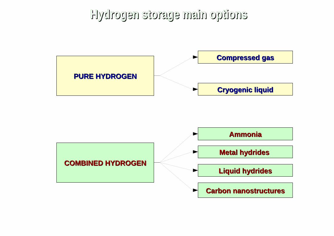
PURE HYDROGENPURE HYDROGEN
Compressed gasCompressed gas
Cryogenic liquidCryogenic liquid
COMBINED HYDROGENCOMBINED HYDROGEN
Metal hydridesMetal hydrides
Liquid hydridesLiquid hydrides
Carbon nanostructuresCarbon nanostructures
AmmoniaAmmonia
Hydrogen storage main optionsHydrogen storage main options

Although the energy need for compression could be even zero (e.g. electrolytic hydrogen produced directly at 20 Mpa), generally it is anything but negligible: for example, at the same final pressure, hydrogen compression requires much more energy compared to methane.The adoption of a multistage configuration with inter-refrigeration allows to reduce the amount of energy spent.
Data provided by Burckhardt Compression show how an intercooled 5-stage volumetric compressor can compress 1000 kg/h of hydrogen up to 200 bar with a specific energy consumption of about 8% of the hydrogen HHV.
Hydrogen compressionHydrogen compression

Electrochemical compressorsElectric energy applied to a proton exchange membrane cell is able to decompose hydrogen in protons and electrons and force the protons to cross the membrane. The membrane separates a low pressure anode from a high pressure cathode in such a way that high pressure hydrogen is generated when protons recombine with electrons at cathode. Combining in series several cells the final pressure could reach values as high as 800-1000 bar. These compressors are compact and have no moving parts.
Ionic (liquid piston) compressorsAn ionic liquid shows a very low vapor pressure and a very large range of temperature for the liquid phase. Hydrogen is almost insoluble in many ionic liquids so that a liquid piston can compress hydrogen at very high pressure (e.g. 1000 bar) without absorbing hydrogen and without release vapour into hydrogen. The heat generate by compression is absorbed by the liquid so that the compression work approaches that of a isothermal compression. Moreover the number of components is significantly reduced. This technology has been used by Linde for hydrogen refuelling stations.
Hydride compressorsMetal hydrides are able to absorbe hydrogen at low pressure and desorbe hydrogen at high pressure by using heat. These compressors are very compact and without moving elements, but are also very heavy and expensive.
Hydrogen compression: new technologiesHydrogen compression: new technologies

Currently hydrogen is mainly distributed in the gaseous state by:➢ packs consisting of 16-20 cylinders and transported by lorry;➢ tank wagons, i.e. semi-trailers equipped with a protective framework which contains a
series of cylinders which may contain 300-400 Nm3 of compressed hydrogen at 20 MPa; to avoid hydrogen embrittlement, chromium-molybdenum steel is generally used;
➢ pipelines, with diameters of 25-30 cm for average pressures of 10-20 bar.
In a developed market the distribution over long distances of gaseous hydrogen would have characteristics similar to those of natural gas distribution and, in fact, it is not a new technology: in 1939 an over 200 km hydrogen pipeline was built in Germany. This option allows to eliminate the risks of road transport and to guarantee a constant supply. However, the current global extension of the hydrogen pipelines is limited to a few thousand km because of the high costs of the system due to the greater care required for the sealing problems, the greater value of the materials used to avoid the risks of embrittlement, the need for detectors leakage and for suitable safety devices. These costs are justifiable only in the presence of large size concentration of users.
Distribution of gaseous hydrogenDistribution of gaseous hydrogen

Gaseous hydrogen is often sold in steel tanks of 50 l and 20 MPa, but the overall dimensions are still very high (about 16 times higher than that of gasoline, with the same energy content).
For higher pressures, the advantage in terms of size is small compared to the penalty in terms of weight increase of the cylinders.
Gaseous hydrogen stored in steel cylindersGaseous hydrogen stored in steel cylinders
0 10 20 30 40 50 60 700
1
2
3
4
5
Ev [MJ/l] Ep [MJ/kg]
Pressione [MPa]
De
nsi
tà e
ne
rge
tica
Pressure [MPa]
E
ne
rgy
de
nsi
ty
Decreasing diameter → Increasing compactnessIncreasing pressure
Increasing thickness → Increasing weight

35-70 MPa35-70 MPa
To overcome this, tanks made of composite or semi-composite material are used. They consist of an inner layer, called liner, which acts as a barrier to permeation and an outer layer, called shell, with a function of resistance to corrosion, impact and fatigue stress. The liner is made of aluminum or polymer matrix material, while the shell is made of epoxy matrix material loaded with carbon fiber.
The weight is 3-4 times lower than that of traditional type cylinders.
They are able to operate at pressures up to 700 bar and are adaptable in terms of shape. Therefore they allow to obtain hydrogen storage densities suitable for use on board vehicles.
The safety features are usually very high, thanks to the robustness of the tanks and the introduction of explosion-proof fuses in the event of fire and shut-off valves in the event of a collision.
Gaseous hydrogen stored in composite material cylindersGaseous hydrogen stored in composite material cylinders
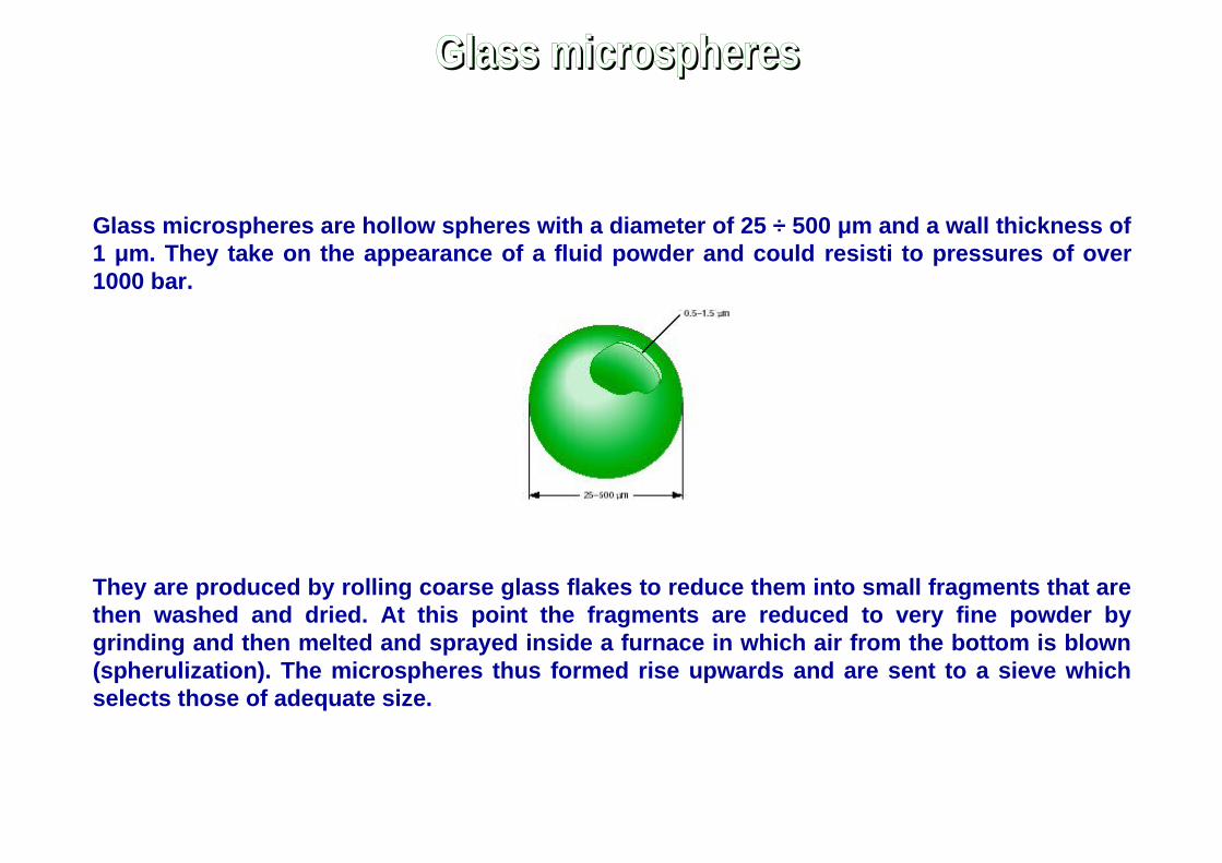
Glass microspheres are hollow spheres with a diameter of 25 ÷ 500 μm and a wall thickness of m and a wall thickness of 1 μm and a wall thickness of m. They take on the appearance of a fluid powder and could resisti to pressures of over 1000 bar.
They are produced by rolling coarse glass flakes to reduce them into small fragments that are then washed and dried. At this point the fragments are reduced to very fine powder by grinding and then melted and sprayed inside a furnace in which air from the bottom is blown (spherulization). The microspheres thus formed rise upwards and are sent to a sieve which selects those of adequate size.
Glass microspheresGlass microspheres

Microspheres are placed in a tank in which the vacuum is made. At high temperature microspheres become permeable to hydrogen and therefore high pressure hydrogen at 200÷400 °C is supplied to tank and fills the microspheres. Subsequently the tank is cooled and the hydrogen remains trapped. To recover the hydrogen, a new heating is performed. If, for example, hydrogen is burned in an endothermic engine, high temperature exhaust gases are enough hot to heat the microspheres; if, on the other hand, a polymeric membrane fuel cell is used, an electric heater powered by the cell itself is necessary. It is also possible to free the hydrogen from the microspheres by breaking them, but this obviously affects their reuse.
They could theoretically contain hydrogen at 62 MPa with a weight density of 10% and reach 95% of the maximum capacity after 15 minutes of refueling.Among the pure hydrogen systems are the safest.The cost should be limited, but it seems that it is not easy to obtain an acceptable dimensional homogeneity.
Gaseous hydrogen stored in glass microspheresGaseous hydrogen stored in glass microspheres

p=1 atm Oxygen Nitrogen Argon Hydrogen
90.18 K 77.35 K 87.3 K 20.27 K
50.35 K 63.14 K 83.8 K 14.025 K
Tboiling
Tfusion
Matter aggregation statesMatter aggregation states
solid liquid aeriform plasma
sublimation
melting
solidification
vaporisation
condensation
ionisation
recombination
deposition
enthalpy

Hydrogen can be stored as a liquid at a temperature of about -253 °C.Traditional Linde or Claude cycles allow to obtain hydrogen liquefaction: they consist of compression stages followed by heat exchangers, rolling valves and expanders.At 1 bar LH
2 has an energy content of about 8.49 MJ/l, while a compressed GH
2 tank at 350 bar
reaches just 3 MJ/l.
Liquid hydrogenLiquid hydrogen
Gaseous and liquid hydrogen comparison
Trailer for compressedgaseous hydrogen
Total weight 40 tHydrogen 530 kg
Trailer for liquid hydrogen
Total weight <40 tHydrogen 3370 kg

The simplest liquefaction process is the Linde process, which is
based on the Joule-Thompson effect.
TTi,maxi,max
μ=( ∂T∂ p )h
⇒
∂ p<0(expansion)∂T <0(cooling)
The liquefaction process requires
that hydrogen be pre-cooled to
temperatures below the inversion
temperature and the maximum
hydrogen inversion temperature is
about -71 °C.
∂ p<0 (expansion)∂T >0 (heating)
μ>0⇒
μ<0⇒
Joule-Thompson eJoule-Thompson effectffect
μ>0
μ<0
He 40 K
202 KNe 231 K
621 KAir 673 K
764 K
1500 K
H2
N2
O2
CO2

Compression
Cooling with nitrogen down to 80 K
Conversion to para-hydrogen
H2 to the Brayton
cycle
Cooling with recirculated H2
We must take into account the spontaneous, but very slow and exothermic transformation from ortho- to para- hydrogen. Therefore it is necessary to accelerate such a transfiormation during the liquefaction process. The energy consumption for liquefaction is very high, in the range from 20-30% of the energy content of hydrogen.Furthermore, for every day of non-use, about 1% of the stored hydrogen evaporates and must be eliminated for safety issues.
Re-compression
Recirculated gaseous hydrogen
Hydrogen liquefactionHydrogen liquefaction

Linde liquefaction plantLinde liquefaction plant

The tanks for liquid hydrogen must be adequately insulated as the thermal energy coming from
the external environment at a higher temperature causes the vaporization of a fraction of the
contained hydrogen (Boil-off).
Cryogenic tankCryogenic tank
Tank for liquid hydrogen (70-140 litres)
Isolated and cooled
Isolated
Boil-off losses after 10-15 days

Ammonia (NH3) has a hydrogen content of 17.6%. At a temperature of 25 °C and ambient
pressure it is a toxic gas and has a very pungent and penetrating odor, besides having tear-gas effects. It can be stored as a cryogenic liquid at about -40 °C or mixed with water in ambient conditions.
Ammonia production and distribution technologies are widely spread and tested as one of the most commercialized products, however the power consumption for production is high.
Hydrogen extraction from ammonia requires a reforming process and does not involve any kind of harmful emissions.
Ammonia can also be used directly as a fuel or in mixture with other fuels. Some years ago, a hybrid vehicle prototype has been realized, equipped with an internal combustion engine fueled with an air/ammonia mixture enriched with 5% of hydrogen produced by on-board thermocatalytic decomposition of the ammonia itself.
AmmoniaAmmonia

There are organic compounds, which are liquids at ambient conditions, that can be converted into other organic compounds, also liquid at ambient conditions, making them react, under appropriate conditions, with hydrogen. The new compound is improperly called liquid hydride.
The most typical example is the toluene/methylcyclohexane system:
The characteristics of these compounds do not differ from those of traditionally used liquid fuels.
The hydrogen release process is endothermic and, although it is different from those already seen for fossil fuels, has the same difficulties related to the high temperatures required.
Compared to the reforming process, this process avoids the release of carbon dioxide, but compels to accumulate the less hydrogenated compound.
H 6+C6H 5⋯CH 3⇒C6H 11⋯CH3
Liquid hydridesLiquid hydrides

Hydrogen can easily bond in a reversible way with different metals and metal alloys. Therefore, the gaseous hydrogen can be absorbed at comparatively low pressures (up to 5 MPa) in the interstitial spaces to form a new compound called hydride.
The absorption-desorption kinetics is governed by heat transfer: the formation of the metal-hydrogen bond releases heat, whereas heat is required for desorption and this makes safer this type of storage.
Metal hydridesMetal hydrides

Initially, hydrogen enters the metal matrix without creating hydride: for a given temperature, an increasing pressure of supplied hydrogen is required.Subsequently begins a region called "plateau": in such a region the hydride is formed in ideally isotermobaric conditions.At the end of this phase it is still possible to introduce hydrogen, but this occurs at increasing pressures and the introduced hydrogen is dispersed in the hydride matrix.
In real hydrides the hydriding process is not isotermobaric and there may be more than one plateau region.In any case, the plateau region globally covers about 80% of the total storage capacity and therefore the hydrogen storage and release operations never leave this region.
Hydriding a metalHydriding a metal

The volumetric density is considerable, comparable to that of liquid hydrogen. Unfortunately the weight is very high and the storage capacity is, on average, only 1.5 ÷ 6.2% by weight.
Other critical issues, in addition to the cost, are the poisoning phenomenon, the recharging time (10-20 minutes) and the slow response that forces to have a small tank of gaseous hydrogen to face the transients.
The distribution infrastructure can be similar to that of gaseous hydrogen.
If there is no poisoning, 100,000 charge cycles can be exceeded.
Characteristics of metal hydridesCharacteristics of metal hydrides
Metals Hydrides Mass(%)

Metal hydrides tanksMetal hydrides tanks

Carbon nanotubes are cylindrical graphitical structures closed at both ends. They were discovered in 1991 by the Japanese scientist Iijima during the study of deposits on the cathode of an electric arc for the synthesis of fullerene.Shortly after two other researchers from the same laboratory demonstrated taht varying the arc operating conditions large quantities of nanotubes could be produced.These nanotubes were made up of several walls, but in 1993 very thin single-wall nanotubes were obtained, by adding cobalt to graphite electrodes. In 1996 Smalley obtained single wall nanotubes of almost uniform diameter.
Carbon nanotubesCarbon nanotubes

Carbon nanotubes have diameters from 1 to 100 μm and a wall thickness of m and therefore have a very large ratio surface/volume and are capable of absorbing hydrogen up to 5.5% by weight (at 82 K and 0.07 MPa). However, the data on the capacity of accumulation of carbon nanostructures are very different from one laboratory to another and therefore other studies are still needed to prove that these structures are suitable as a hydrogen storage system.
There are also other hydrogen storage systems based on carbon structures.Chemically active carbon absorbs hydrogen on the surface when it is subjected to high pressure and low temperature, whereas it releases it at ambient conditions. It can accumulate up to 4.8% of hydrogen (by weight) at 6 MPa and 87 K.
Graphite nanofibers have diameters from 5 to 100 nm and accumulate hydrogen at 4÷5 MPa and ambient temperature. Hydrogen is released almost completely by reducing the pressure. Storage takes place at higher pressures (13.6 MPa) and is a very slow process. Energy density of 70% by weight was claimed, but never experimentally re-obtained. A fuel cell car with a tank of 25 l and 90 kg would allow to travel 8,000 km!
Also for these other nanostructures the values vary from one laboratory to another and on average, as for nanotubes, the experimental results are only around 1 ÷ 2%.
Carbon nanostructuresCarbon nanostructures

MaterialTemperature Pressure Hydrogen Specific energy Hydrogen Energy density
[K] [bar] [weight %] [kWh/kg] [Volume %] [kWh/l]300 0.65 480 70.9 8.25
MWNT 298-773 1 0.4 0.133 3.2 0.106Li-MWNT 473-673 1 20 6.66 180 6.0
K-GIC 313 1 57.85 1.66 60 2Li-GIC 473-673 1 14 4.66 280 9.32
GNF (tubular)298 112 11.26 1.42298 110 10-12
298 112 57.85 13.35
Graphite 298 112 4.52 0.53SWNT single-walled nanotube, MWNT multiwalled nanotube, GIC graphite intercalated compounds, GNF graphite nanofibers
SWNT, high purity
GNF (herringbone)
Characteristics of carbon nanostructuresCharacteristics of carbon nanostructures

GASEOUS HYDROGENGASEOUS HYDROGEN
SuppliedSupplied
Generated onsiteGenerated onsite
LIQUID HYDROGENLIQUID HYDROGEN Supplied as a gasSupplied as a gas
Generated onsiteGenerated onsite
Supplied as a liquidSupplied as a liquid
For safety reasons, hydrogen refuelling stations require very large spaces.
Refuelling stationsRefuelling stations

The hydrogen, supplied or produced on site, must be compressed in a tank at a pressure higher than that stored on board of the vehicle.If the hydrogen is supplied, the filling station must be equipped with a bay for the stop of the truck transporting hydrogen. In the case of hydrogen produced on site, the station is equipped with a production unit, which could be an electrolyser or a hydrocarbons reformer with a purification unit.
The local production of hydrogen is less efficient and installation costs are much higher, but has the advantage of continuity of service and the absence of distribution costs.
Gaseous hydrogen refuelling stationsGaseous hydrogen refuelling stations

A filling station consists of a cryogenic tank served by a suitable refrigeration system, an insulated piping powered by a cryogenic pump and a supply column that allows refuelling in the liquid state.
If hydrogen is not supplied directly by cryogenic tankers, a liquefaction unit and, possibly, a hydrogen production system are also required.
Linde has patented a system capable of supplying vehicle tanks at around -254 °C without ice formation and with a refuelling time comparable to those for natural gas vehicles.
Liquid hydrogen refuelling stationsLiquid hydrogen refuelling stations

From a safety point of view, the best systems are glass microspheres and metal hydrides since they require heat at a temperature generally higher than the environment. Chemical hydrides can also be considered safer than other systems.Regarding energy density, it is necessary to differentiate between mobile and fixed applications. In the first case, in fact, weight is fundamental, whereas it is not in the second. Therefore, for mobile applications cryogenic systems and chemical hydrides are generally preferable, whereas metal hydrides and gaseous hydrogen may be suitable for stationary applications. Liquid hydrides may be suitable for mobile applications if the size of the dehydrogenation reactor is reduced.Refuelling time is also a critical issue for mobile systems and even in this case cryogenic systems, liquid hydrides and chemical hydrides are preferable.Finally, for the fastest response, the best systems are gaseous and liquid hydrogen, liquid hydrides and chemical hydrides.
Hydrogen storage options comparisonHydrogen storage options comparison