universiti putra malaysia power quality improvement...
TRANSCRIPT

UNIVERSITI PUTRA MALAYSIA
POWER QUALITY IMPROVEMENT USING DISTRIBUTION STATIC COMPENSATOR (D-STATCOM) ON 11 kV DISTRIBUTION SYSTEM
NOOR IZZRI BIN HJ ABDUL WAHAB
FK 2002 63

POWER QUALITY IMPROVEMENT USING DISTRIBUTION STATIC COMPENSATOR (D-STATCOM) ON 11 kV DISTRIBUTION SYSTEM
By
NO OR IZZRI BIN HJ ABDUL WAHAB
Thesis Submitted to the School of Graduate Studies, Universiti Putra Malaysia, in Partial Fulfillment of the Requirement for the Degree of Master of Science
July 2002

Dedicated to my loving family, for their endless support
11
Abstract of thesis presented to the Senate of Universiti Putra Malaysia ill partial fulfillment of the requirement for the degree of Master of Science
POWER QUALITY IMPROVEMENT USING DISTRIBUTION STATIC COMPENSATOR (D-STATCOM) ON 11 kV DISTRIBUTION SYSTEM
By
NOOR IZZRI BIN HJ ABDUL WAHAB
July 2002
Chainnan: Associate Professor Norman Mariun, Ph.D., P.Eng.
Faculty: Engineering
Tile increased awareness ill power quality issues has brought tremendous changes and
improvement� in power electr0nics devices. Various c ircuit topologies and contf0l
techniques have been developed aimed at mitigating power quality disturbances .
Custom Power concept is one of technological responses to the poor power quality
presently surfacing in factories, offices and homes. It is dedicated to maintaining and
improving the quality and reliability of distribution level power and to protecting
customers against disturbances generated by other users in the network. Custom Power
(CP) family includes power electronics based devices such as Distribution Static
Compensator (D-STATCOM), Dynamic Voltage Restorer (DVR), Solid State Fault
CUlTent Limiter (SSFCL), Active Power Filter (APF) and Solid State Transfer Switch
(SSTS). The CP concept is the customer's solution by the utilities sector.
111

In this research work, the focus will be on one of the CP family, that is, the D
STATCOM. The D-STATCOM, which consists of a thyristor-based voltage source
inverter, uses advanced power electronics to provide voltage stabilization, power factor
correction, harmonic control and a host of other power quality solutions for both utility
and industrial applications.
This thesis describes the configuration, design and control of the 12-pulse 0-
STATCOM. Its simulation works are done by using PSCADIEMTDC version 3.0. 7
software, developed by Manitoba HVDC Research Center, Canada. The designed 0-
ST ATCOM is connected in shunt to an 11 k V test distribution system Simulations have
beeu carrieu out to illustrate the effectiveness of the D-STATCOM in mitigating voltage
sags and voltage unbalance as well as eliminating harmonics. The results obtained from
the simulations clearly showed that the designed D-ST ATCOM is capable in mitigating
voltage sags and voltage unhalance. Furthermore, by connecting passive filters in shunt
at the primary side of the step-down transformer reduces the harmonics generated by the
D-STATCOM.
lV

Abstrak tesis yang dikemukakan kepada Senat Universiti Putra Malaysia sebagai memelluhi sebahagian daripada keperluall untuk ijazah Master Sains
MENANGANI MASALAH KUALITI KUASA DENGAN MENGGUNAKAN PEMAMPAS STATIK (D-STATCOM) PADA SISTEM AGIHAN 11 kV
Oleh
NOOR IZZRI BIN HJ ABDUL WAHAB
Julai 2002
Pengerusi: Profesor Madya Nonllan Mariun, Ph.D., P.Eng.
Fakulti: Kejuruteraan
Peningkatan kesedaran dalam isu kualiti kuasa telah membawa banyak perubahan dan
evolusi dalam peranti elektronik kuasa. Topologi dan teknik kawalan yang berbagai
telah direka untuk menangani masalah kualiti kuasa. Konsep Kuasa Langganan adalah
merupakan salah satu teknologi yang boleh menangani masalah kualiti kuasa yang
rendah yang sering dialami di kilang-kilang, pejabat, dan kawasan perumahan. Kuasa
Langganan adalah bertujuan untuk mengekal dan meningkatkan kualiti kuasa dan untuk
melindungi pelanggan daripada gangguan yang dijana oleh pengguna sendiri. Keluarga
peranti-peranti Kuasa Langganan adalah tennasuk Pemampas Statik (D-ST ATCOM),
Pemulih Voltan Dinamik (DVR), Penghad Arus Kerosakan Pepejal (SSFCL), Penapis
Kuasa Aktif (APF) dan Suis Pemindah Keadaan Pepejal (SSTS). Konsep Kuasa
Langganan adalah penyelesaian bagi masalah pelanggan daripada sektor pembekal.
\'
Dalam kajian illi, fokus akan diberikan kepada satu daripada per anti Kuasa Langganan
iaitu, D-ST ATCOM. Ianya menggunakan peranti elektronik kuasa untuk menstabilkan
voltan, mengurangkan kerlipan, membetulkan faktor kuasa dan kawalan harmonik. Tesis
ini menerangkan konfigurasi, reka bentuk dan kawalan D-STATCOM I2-denyut.
Simulasi ul1tuk D-ST ATCOM akan dijalankan dengan menggunakan program
PSCADIEMTDC versi 3.0. 7 yang direka oleh Manitoba HYDC Research Center,
Kanada. D-ST A TeOM yang telah direkabentuk akan disambungkan secara selari
dengan system agihan 11 kY. Simulasi yang telah dijalankan menggambarkan D
STATCOM efektif dalam menangani masalah voltan lendut dan voltan tidak stabil serta
mengurangkan hannonik. Keputusan yang diperolehi secara terang menunjukkan D
STATCOM yang Jilekabemuk berkebolehan daiam menangani masalah voltan lendut
dan voltan tidak stahil. Seterusnya, dengan menyambung penapis pasif pada bahagian
primer transformer telah mengurangkan harmonik yang dijana oleh D-STATCOM.
Vl

ACKNOWLEDGEMENTS
In the Name of Allah, Most Gracious, Most Merciful
I am truly grateful to Allah The Almighty. for glvmg me strength and patience to
complete this research work. I would like to thank Allah also for giving me good health
throughout the research until the completion of this thesis.
I would like to express my deepest gratitude to my supervisory committees, Assoc. Prof.
If. Dr. Nomllm Mariun (UPM) - Chairman, Assoc. Prof. Dr Azah Mohamed (UKM) and
A ���� n-of Dr �Kohib··ll�t.. /TTP"",r\ c�_ �heli'- �-dles� suppo-g"l'd�il�e 1,:_--1 ••• �_--1� n��'_J\ ... � 1 . • lY� UllUll "U - 1\1.1), lVl l \;.,11 � ll, U '41 y- , l\.lllU WVIU�,
encouragement, ideas and help throughout my research work.
I would like also to thank my parents and family for their kind support, understanding
and encouragement during the course of my Master program.
Many thanks are also to all my colleagues, friends and UPM support staff.
vii

I certify that an Examination Committee met on 8th July 200 2 to conduct the final examination of Noor Izzri bin Abdul Wahab on his Master of Science thesis entitled "Power Quality Improvement Using Distribution Static Compensator (D-Statcom) on 11 kV Distribution System" in accordance with Universiti Pertanian Malaysia (Higher Degree) Act 1980 and Universiti Pertanian Malaysia (Higher Degree) Regulations 1981. The Committee recommends that the candidate be awarded the relevant degree. Members of the Examination Committee are as follows:
SENAN MAHMOD, Ph.D. Department of Electrical and Electronic Engineering, faculty of Engineering, Universiti Putra Malaysia. (Chairman)
NORMAN MARIUN, Ph.D. Associate Professor, Department of Electrical and Electronic Engineering, Faculty of Engineering, Universiti Putra Malaysia. (Member)
AZAH MOHAMED, Ph.D. Associate Professor, Department Electrical, Electronic and System Engineering, Faculty of Engineering, Universiti Kebangsaan Malaysia, (Member)
MOHIBULLAH, Ph.D. Associate Professor, Department of Electrical and Electronic Engineering, Faculty of Engineering, Universiti Putra Malaysia. (Member)
7
AMSHER MOHAMAD RAMADILI, Ph.D. Professor / Deputy Dean, School of Graduate Studies, Universiti Putra Malaysia.
Date: 2 � /" ,_" 2002
VIII
The thesis submitted to the Senate of Universiti Putra Malaysia has been accepted as a partial fulfillment of the requirement for the degree of Master of Science. The members of the Supervisory Committee are as follows:
NORMAN MARIUN, Ph.D. Associate Professor, Department of Electrical and Electronic Engineering, Faculty of Engineering ,
Universiti Putra Malaysia. (Chairman)
AZAH MOHAMED, Ph.D. Associate Professor, Dcpanmcnt Elcctricai, Electronic and System Engineering, Faculty of Engineering, Universiti Kebangsaan Malaysia, (Member)
MOHIBULLAH, Ph.D. Associate Professor, Department of Electrical and Electronic Engineering, Faculty of Engineering, Universiti Putra Malaysia. (Member)
IX
AINI IDERIS, Ph.D. Professor I Dean, School of Graduate Studies, Universiti Putra Malaysia.
Date:

DECLARA TION
I hereby declare that the thesis is based on my original work except for equations and citations which have been duly acknowledged. I also declare that it has not been previously or concurrently submitted for any other degree at UPM or other institutions.
Date: 26th August 2002

TABLE OF CONTENTS
DEDICATION ABSTRACT
11 III V ABSTRAK
ACKNOWLEDGEMENTS APPROVAL SHEET 1 APPROVAL SHEET 2 DECLARA TION FORM LIST OF TABLES
V11 Vlll IX X
Xlll LIST OF FIGURES XIV
XV11 LIST OF ABBREvIAtION
CHAPTER
1 INTRODUCTION 1 1 Research Background 1 2 Proposed Solution 1 3 ObjectIves of Research 1 4 Scope of The':;l':; 1 5 Importance of Research
2 LITERA TURE RIVIEW
1 3 6 7 7
2 1 Power qualIty Problems m DlstnbutIon System 9 2 2 D- STATCOM ill Mlt1gatmg Power Qualtty Problems 1 3 2 3 Powel QUdltty Standmds 13
2 3 1 Voltage Sags 14 2 3 1 1 Deflllltlon and CharactenStiCS of Vo ltage Sags 14 2 3 1 2 Sources of Voltage Sags 15 2 3 1 3 Effects of Voltage Sags 1 6
2 3 2 HafIl10111CS 1 6 2 3 2 1 Defillition and CharactenstIcs of HarmOlllCS 1 6 2 3 2 2 SOUl l-el> of Hdf1l10111l-1> 1 8 2 3 2 3 Harmollic Content 1 8 2 3 2 4 Effects of Harmolllcs 20
2 3 3 Unbalanced Voltage 20 2 3 3 1 DeflllltiOn and CharactenstIcs of Unbalanced Voltage 2 1 2 3 3 2 Sources of Unbalanced Voltage 21 2 3 3 3 Effects of Unbalanced Voltage 22
2 4 D-ST A TeOM Theory 23 2 4 1 D-ST ATCOM BaSIC Configuration and De.:;cnptlOm 23 2 42 Ba<;K OperdtlOn of D-STATCOM 2 4 2 43 Modehng of D-STATCOM 27 2 44 OperatIon of 1 2-pul<;e Bndge As Rectlfiel And Inverter 30 2 4 5 SelectIon of Pa%IVe Element'> 33 2 4 6 Control of O-ST ATCOM 3 4
Xl
2.4.7 PWM Switching Techniques. . .. . .. . . . . . . . . . . .. . .. . .. . .. . .. . .. . . . . . 36 2.5 Trends in D-STATCOM Research Work 37
3 MATERIAL AND METHODS 3.1 Brief Description on PSCADIEMTDC .................................. .
3.2 The Distribution System for Simulation ................................ .
3.3 Design of the Proposed D-ST ATCOM .................................. .
3.4 Selection of Power Electronic Switches ... , . . . . . . . . . . . . . . . . . . . . . . . . . . . . .
3.5 Selrrtinn of Pa�sive Elements .................................... , . . . . . . . .
3.6 D-STATCOM Power Quality Mitigation Strategies .................. .
3.6.1 Voltage Sags Model ................................................. . 3.6.1.1 Voltage Sag Calculations .................................. .
3.6.1.2 Voltage Sag Control Strategies ........................... .
3.6.2 Harmonics Order Generated by the D-ST ATCOM ............. .
3.6.2.2 Harmonics Mitigation Strategy ........................... .
3.6.3 Unbalancrd Voltage .. . . . . . . . . . . . . . . . . . . . . . . . . . . . . . . . . . . . . . . . . ... . . .. .
3.6.3.1 Unbalanced Voltage Calculations ........................ .
3.6.3.2 Voltage Unbalance Control Strategy .................... .
4 RESUL TS AND DISCUSSION
40 41 43 45 46 49 50 51 52 55 56
58 60
4.1 Analysis a.ml Operation of D-3T ATCOM in Miti gatin g Vo Itage 6 i Sags . . . . . . . . . . . . . . . . . . . . . . . . . . . . . . . . . . . . . . . . . . . . . . . . . . . . . . . . . . . . . . . . . . . . . . . . . . .
4.2 Analysis for Elimination of Generated Harmonics from the D- 71 STATCOM ................................................................. .
4.3 Analysis and Operation of D-STATCOM in Unbalanced Voltage 75 Condition ................................................................... .
5 CONCLUSION AND FUTURE WORK 5. 1 Conclusion . . . . . . . . . . . . . . . . . . . . . . . . . . . .. . . . . . . . . . . . . . . . . . . . , . . . . .. . ... .. . .. . .. 82 5.2 Future Work. . .. . . . . . . . . . . . . . . . . . . . . . . . . . . . . .. . . . . . . . .. . . . . . . . .. . .. . .. . .. . .... 83
REFERENCES 85
APPENDICES A - CIRCUIT USED FOR SIMULATION - LA YOUT IN 89
PSCADIEMTDC ...................................... . . . . . . . . . . . . . . . . . B - SOME COMPONENTS HELP FILES . . . . . . . . . . . . . . . . . . . . . . . . . . . . . . . . . . 93
BIODATA OF THE AUTHOR 108
Xll
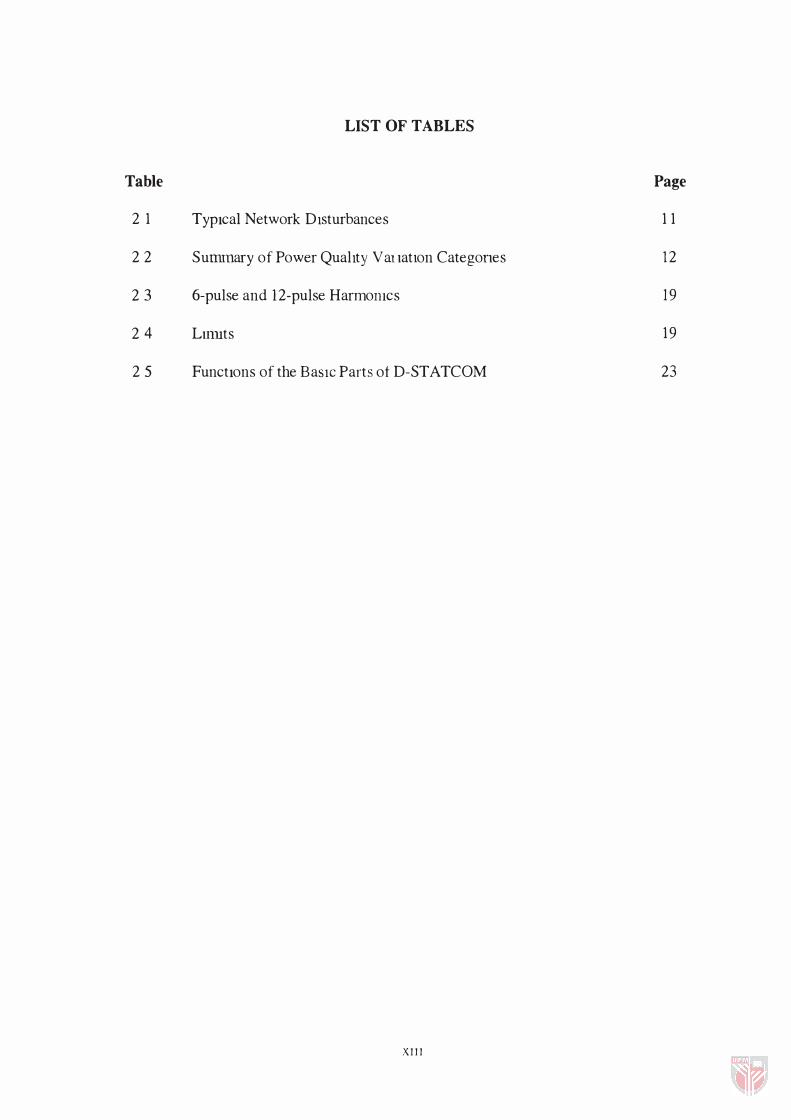
LIST OF TABLES
Table Page
2 1 TypIcal Network DIsturbances 11
22 Sununary of Power QualIty V m latlon Categones 12
23 6-pulse and 12-pulse Harmol11cs Content 19
24 Lllruts of THD 19
25 FunctIons of th e BaSIC Parts ot D-ST A TCOM 23
X III
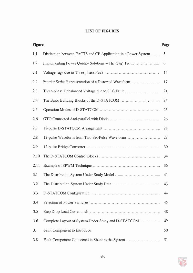
LIST OF FIGURES
Figure Page
1 .1 Distinction between FACTS and CP Application in a Power System . . . . . . . 5
1 .2 Implementing Power Quality Solutions - The 'Sag' Pie . . . . . . . . .. . .. . . .. . . . . . . 6
2 .1 Voltage sags due to Three-phase Fault . . . . . . . . . . . . . . . .. . . . . . .. .... .. . . . . . . . . . .. . 1 5
2.2 Fou.rier Series Representation of a Di�t0rted Waveform.... ... . . . . .. . . . . . . . . . 17
2 .3 Three- phase Unbalanced Voltage due to SLG Fault . . . . . . . . . . . . ..... . . . . . . . . . . 21
2 .4 The Basic Buildulg Blucks of the D-STATCOM . .. . . ... . . ... . . . . 24
2 .5 Operation Modes of D-STATCOM . . . . . . . . . . . . . . . . . . .... . .. . .. ... ... .... ........ 2 5
2 .6 GTO COlmected Anti- parallel with Diode . . . . . . . . . . . . . . . . . . . . . . . . . . . . . . . . . . . . ' " 2 6
2 .7 12 - pulse D- STATCOM Arrangement . . . . . . . . . . . . . . . . . . . . . . . . . . . . ... . .. . . . . . . . . . . 2 8
2 .8 12 - pulse Waveform from Two Six-Pulse Wavefonns . . . . . . . . . . . . . . . . . . . . . . . . . 2 9
2 .9 12 -pulse Bridge Converter . . ... . . . . .. " . .. . . . .. . . . . . .. . . . . .. ... . .. .... .... .. .. . .. . . 30
2 .1 0 The D-STATCOM Control Blocks . . . . . . . . . . . . . . . . . . . . . . . . . . . . . . . .. . .. . . . . . . . . . . . 34
2 .11 Example of SPWM Technique .. . . . . . . . . . . . . . . . . . . . . . " . . . . . . . . . . . . . . . . . . . . . . . . . . . 36
3 . 1 The Distribution System Under Study Model . . . . . . . . . . . . . . . . . . . . . . . . . . . . . . . . . . . . 41
3 .2 The Distribution System Under Study Data . . . . . . . . . . . . . . . . . .. . . . . . . . .. . . . . . . . . . 43
3 .3 D- ST ATCOM Configuration . . . . . . . . . . . . . . . . . . . . . . . . . . . . . . . . . . . . . . . . . . . . . . . . . . ' " . 44
3 .4 Selection of Power Switches .. ... . . . . .. . . . . . ... . . . . . . . . . . . . . . . . .. . .. . . . . .. . . . . .. .. 45
3.5 Step Drop Load CUlTent, �h. . . . ... . .. ... . . . . . . . . . . . . .. . . . . . .... ........ . .. . .. . . . . . 48
3 .6 Complete Layout of System Under Study and D-STATCOM .. . .... . ... . . . . . 49
3 . 7 Fault Component to Introduce Voltage Sag in the System.......... ....... ... 50
3 .8 Fault Component Connected in Shunt to the System. ........ ... ......... .. .. .. 51
XIV
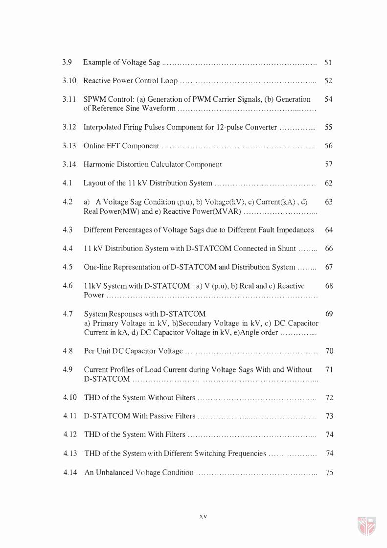
3.9 Example of Voltage Sag . . . . .. . . . . . . . . . . . . .. . . . . . . . . . . . . . . .. . . . . ... . . . . . . . . . .. . .. . . . 51
3 .1 0 Reactive Power Control Loop . . .. .. .. . . . . .. . . . . . . . . . .. . . . ... . . . .. . . . . .. .. .. ... . ... 52
3 .11 SPWM Control: (a) G eneration of PWM Carrier Signals, (b) G eneration 54 of Reference Sine Waveform . .. . . . . . . . . . .. .. . . . .. . . . . .. . .... . . . . . ... . . . . . . . . ... . . .
3 .1 2 Interpolated Firing Pulses Component for 1 2 -pulse Converter . . . . . . . . . .. . . . . 55
3 .1 3 Online FFf Component... ......... ... . . ........... . ........... ... . ........ ...... .. 56
3.1 4 Harmonic Distortion Calculator COlll-POnent 57
4.1 Layout of the 11 kV Distribution System. . . . . .. .. .. . . .. . .. . . . . . ... . .... . .. . . . . . 62
4. 2 a) A Voltage Sag Coauiti0n �p.u), b) '/oltage(kV), c) Current(kA) , d) 63 Real Power(MW) and e) Reactive Power(MV AR) .. .. .. .... . .. . ... . .. . . . . . . .. .
4.3 Different Percentages of Voltage Sags due to Different Fault Impedances 64
4.4 11 k V Distribution System with D-ST ATCOM Conllected in Shunt . . . . . . . . 66
4.5 One- line Representation of D-ST ATCOM ami Distribution System . . . . . . . . 67
4.6 11 kV System with D-STATCOM : a) V (p. u), b) Real and c) Reactive 68 Power . . . . . . . . . . . . . . . . . . . . . . . . . . . . . . . . . . . . . . . . . . . . . . . . . . . . . . . . . . . . . . . . . . . . . . . . . . . . . . . . .
4.7 System.Responses with D- STATCOM 69 a) Primary Voltage in kV, b) Secondary Voltage in kV, c) DC Capacitor Current in kA, d) DC Capacitor Voltage in kV, e)Angle order ... . . . .. . . . . . ..
4 .8 Per Unit DC Capacitor Voltage . . . . . . . . . .. . .. . . .. . . .. . . . . . . . . . . . . . .. . .. .. .. . . . . . . . 70
4.9 Current Profiles of Load Current during Voltage Sags With and Without 71 D-STATCOM ... . . .. . . . ... . . . . . . . . .. . . . . .. .. . . .. . . . . . . .. . . . . . .. . . . . . . . . . . . . . . . .... . .
4.10 THD of the System Without Filters.... . . . . .. .. . . . . ..... . .... .. . ... .. .... . . . ..... 72
4.11 D-STATCOM With Passive Filters. . .. . . . . .. . . . . .. . .... . . .. . . . . .. . .. . .. . . . . . . . . .. 73
4.1 2 THD of the System With Filters . . . . . . .. . . .. .. .. .. ..... . .. .... .................... 74
4.1 3 THD of the System with Different Switching Frequencies...... .. . ... ...... 74
4.1 4 An Unbalanced Voltage Condition........ ........................... ............ 75
xv

4.15 Three- phase Unbalanced Line-to-Line Voltage Proftles """"""""", ,.. 76
4.16 Three- phase Load Current Profiles.... ......... .. . . . . .. .. .. . .. . . . . ............ . . . 77
4.17 System's Layout for Unbalanced Voltage Studies With the D- STATCOM 78
4.18 Three- phase Voltage Proftles during SLG Fault with D-STATCOM 79 Application . . . . . . . . . . . . . . . . . . . . . . . . . . . . . . . . . . . . . . . . . . . . . . . . . . . . . . . . . . . . . . . . . . . . . . . . . . .
4.19 Load Current Profiles dur ing SLG Fault with D-ST ATCOM Application. 80
420 The system's THD, Third Ham1C1nic Magnitude and Per Unit DC Volt[lge 81
XV]
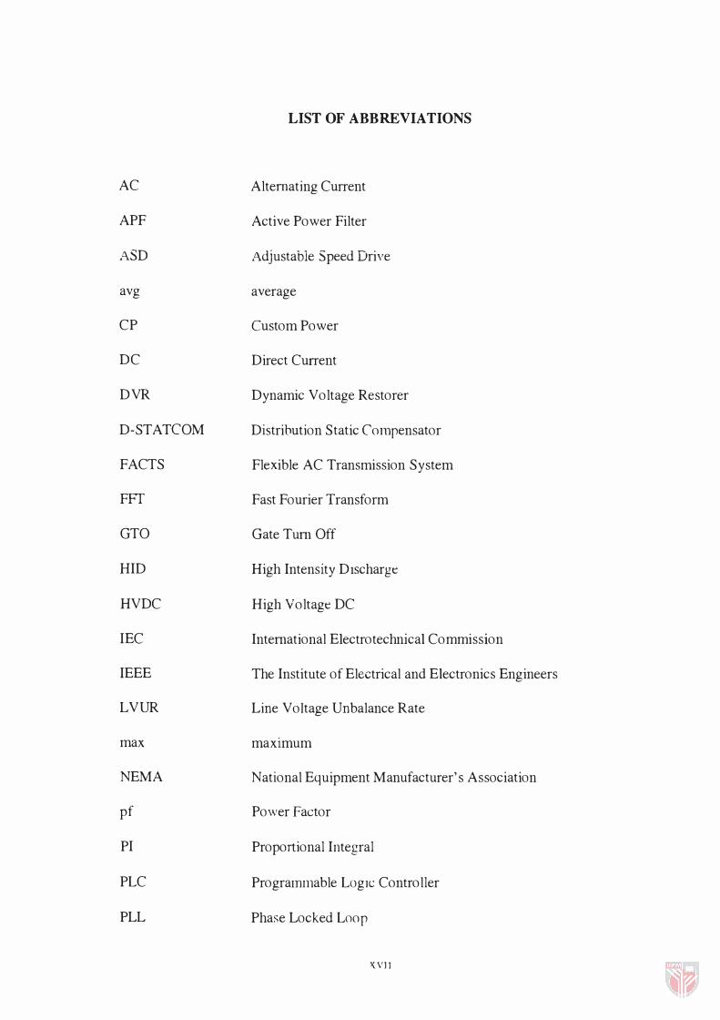
AC
APF
ASD
avg
CP
DC
DVR
D- STATCOM
FACTS
FFT
GTO
HID
HVDC
IEC
IEEE
LVUR
max
NEMA
pf
PI
PLC
PLL
LIST OF ABBREVIATIONS
Alternating Current
Active Power Filter
Adjustable Speed Drive
average
Custom Power
Direct Current
Dynamic Voltage Restorer
Distribution Static Compensator
Flexible AC Transmission System
Fast Fourier Transform
Gate Tum Off
High Intensity DIscharg e
High Voltage DC
Intemational Electrotechnical Commission
The Institute of Electrical and Electronics Engineers
Line Voltage Unbalance Rate
maXImum
National Equipment Manufacturer's Association
Pov..'er Factor
Proportional Integral
Programmable LOgIC Controller
Phase Locked Loop
XVlJ

PQ
PSCADIEMTDC
PVUR
PWM
RM S
SCR
SLG
SPWM
SSFCL
SSTS
SVC
THD
UPS
VAR
VSD
VSC
VUF
Power Quality
Power System CADlElectromagnetic Transients DC
Phase Voltage Unbalance Rate
Pulse Width Modulator
Root Mean Square
Switched Controlled Rectifier
Single Line to G round
Sinusoidal Pulse Width Modulation
Solid State Fault Current Limiter
Solid State Transfer Switch
Static V AR Compensator
Total Harmonic Distortion
Uninterruptible Power Supply
Volt Ampere Reactive
Variahle Speed Drive
Voltage Sourced Converter
Voltage Unbalance Factor
XVlII
CHAPTER 1
INTRODUCTION
Tl!i� �ecti(l!l de�crihe� illiruJuc( lUll to the research work. It will start with some
background on the research work. Then, the solution of the problems will be discussed
through which D-ST ATCOM will be selected. Next, the objectives, scope and
importance of the research are explained.
1.1 Research Background
Electricity supply plays an important role in the economic development and technology
advancement throughout the world. TIle quality and reliability of power supplies relates
closely to the economic growth of a country. However, power quality disturbances such
as sags, swells, flicker, harmonics, voltage imbalance etc., create a lot of problem� in
achieving a reliable and quality povv'er supply. These power quality problems are very
common in the electrical distribution systems [1 ].
Power quality concerns the factors affecting, and the standard of, the received electrical
powel supply [2]. The electric utilities and end users of electrical power are becoming
increasingly concerned about the quality of electric power. There are four major reasons
for the growing concern which are described as follows [3].
1) Load equipment is more sensitive to power quality variations than equipment applied
in the past. Many new load devices contail) microprocessor-based controls and
power electronic devices that are sensitive to many types of disturbances.
2) Th e increasing emph asis on overall power system efficiency h as resulted in a
continued growth in th e application of devices such as h igh -efficiency, adj ustable
speed motor drives and sh unt capacitors for power factor correction to reduce losses.
TIus results in increasing h armonic levels in power systems and h as many people
concerned aboHt the future impaci 011 �ysle1l1 capabilities.
3) Increased awareness of power quality issues by th e end users. Utility customers are
becoming better informed about power quality problems.
4) Many things are now intercOlmected in a network. Integrated processes means th at
th e failure of any component has much more economic consequences.
From th e four maj or reasons stated above it can be deduced th at th e responsibilities and
ch allenges of th e utility sector are great in providing quality, efficient and reliable power
supply to th e end users such as factories, h ouseh olds, illgh er institutions etc. Power
quality is ultimately a customer-driven issue and th e customer's point of reference takes
precedence.
New demands, undoubtedly, are stretch ing th e resources of th e utilities and it is
becoming increasingly difficult to provide a consistent reliable quality of supply, willIe
using existing present day technology [2] . Traditionally, for problems on th e utility side,
th e approach h as been to desensitize critical loads wh ile 'cleaning up' the circuits such as
installing uninterruptible power supplies, alternative feeders, use relatively common
surge suppressor and standby power generators r 4] . However, once th ese efforts h ave
been accomplish ed, there are still many situations where it is not possible to provide
improvement. In th ese cases, customer side solutions usually become very expensive.

Building a new dedicated circuits or substations is difficult for utilities, and may not
even provide the needed degree of improvement.
1.2 Proposed Solution
The increased awareness in power quality Issues has brought tremendous changes and
improvements in power electronics devices. Different circuit topologies, control
techniques and strategies are created aimed at mitigating power quality problems.
The Custom Power concept is one of technological responses to the poor power quality
present ly surfacing in factories, offices and homes [1]. Custom Power is dedicated to
maintaining and improving the quality and reliability of distribution level power
received and to protect customers against disturbances generated by other users on the
network. This is to offer a 'Total Solution' package to the customer [2]. The Custom
Power concept is to provide customer's solution by the utilities sector [1]. Utility
participation occurs at the distribution substation and/or at the front end of the power
supply.
There is also Flexible AC Transmission System (FACTS) devices that are concerned
with improving power in the transmission system The distinction between Flexible AC
Transmission System (FACTS) and Custom Power is shown in Figure 1.1 [1]. The
Custom Power offers the customer no power interruptions, tight voltage regulation, low
harmonic voltage and acceptance of fluctuating and non-linear loads without affecting
the tenninal voltage [4]. The Custom Power family includes Dynamic Voltage Restorer
3
(DVR) , Distribution Static Compensator (D-STATCOM), Solid State Fault Current
Limiter (SSFCL), Solid State Transfer Switch (SSTS) and Active Power Filter CAPP).
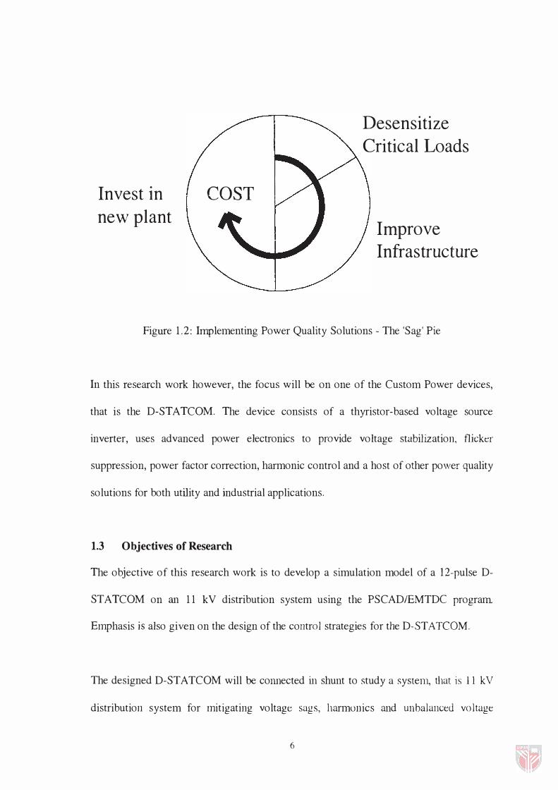
Although the Custom Power concept is very interesting and acceptable, the turning point
will be �he cost. Tllis commo n question will arise, i. e. How much money ha� ttl be
invested in order to install Custom Power products in a distribution system? The route to
improving power quality can be considered as a three stage process, with costs almost
exponentially increasing at each step [5] as shown in Figure 1.2.
The steps start with applying good electrical sense to desensitize critical loads such
alternate supply paths and clear earthing paths, followed by the replacement of weak
parts of the infrastructure. If these measures fail to yield, the solutions will be costly.
Custom Power is intended to provide wide area solution that represents an economic
alternative to the last step of the power quality improving process [5].
It can be anticipated that the cost of components will also reduce in time when they are
produced in bulk, providing cost benefits for large production. Comparing with the
traditional methods of improving power quality, the Custom Power products would
negate the need for the utility to install additional feeders or substation or the customer
to install power conditioners at the load level. Not only would the Custom Power
systems cost less but they would also engender much lower energy [ 11.
4

Power plant
Transformer
TransmissiOI'-,-_-+-----,,..substation
Transmission (FACTS)
120 - 765 kV
Distribution substation
Distribution feeder
������ 3 - 34 kV
Distribution transfonners
Distribution (Custom Power)
Figure 1 .1: Distinction Between FACTS and Custom Power ApplicatIons in a Power System
5
Invest in new plant
COST
Desensitize Critical Loads
Improve Infras tructure
Figure 1.2: Implementing Power Quality Solutions - The 'Sag' Pie
In this research work however, the focus will be on one of the Custom Power devices,
that is the D-STATCOM. The device consists of a thyristor-based voltage source
inverter, uses advanced power electronics to provide voltage stabilization, flicker
suppression, power factor correction, harmonic control and a host of other power quality
solutions for both utility and industrial applications.
1.3 Objectives of Research
The objective of this research work is to develop a simulation model of a 12-pulse D-
ST ATCOM on an 11 kV distribution system using the PSCADIEMTDC program
Emphasis is also given on the design of the control strategies for the D-ST ATCOM.
The designed D-STATCOM will be connected in shunt to study a system., that is 11 kV
distribution system for mitigating voltage sags, harmonics and unbalanced voltage
6