universiti teknikal malaysia melakaeprints.utem.edu.my/18215/1/enhance the performance of condenser...
TRANSCRIPT

UNIVERSITI TEKNIKAL MALAYSIA MELAKA
ENHANCE THE PERFORMANCE OF CONDENSER BY USING
EVAPORATIVE COOLING METHOD FOR SPLIT TYPE AIR
CONDITIONER
This report is submitted in accordance with requirement of the Universiti Teknikal
Malaysia Melaka (UTeM) for the Bachelor of Engineering Technology
(Refrigeration & Air-Conditioning System) with Honours
By
KARTHIGEYAN A/L RAMAKRISHNAN
B071210541
910410-08-5653
FACULTY OF ENGINEERING TECHNOLOGY
2016

DECLARATION
I hereby, declared that this report entitled “Enhance the performance of condenser by
using evaporative cooling method for split type air conditioner” is the results of my
own research except for quotes as cited in references.
Signature : ………………………………………….
Author’s Name : ………………………………………….
Date : ………………………………………….

APPROVAL
This report is submitted to the Faculty of Engineering Technology of Universiti
Teknikal Malaysia Melaka (UTeM) as a partial fulfillment of the requirements for
the award of Bachelor of Mechanical Engineering Technology (Refrigeration & Air-
Conditioning Systems) with Honours. The member of the supervisory is as follow:
………………………………
(Mr. Azwan Bin Aziz)

i
ABSTRAK
Penyaman udara jenis unit terpisah adalah salah satu peralatan yang biasa digunakan di kediaman, bangunan, pejabat dan hotel. Penyaman udara jenis ini dibahagikan kepada dua bahagian iaitu unit pemeluwap dan unit gegelung kipas (unit dalam). Unit pemeluwapan terletak di luar bangunan manakala unit gegelung kipas (unit dalam) terletak di ruang penyamanan dan kedua-dua unit ini disambungkan dengan menggunakan tiub kuprum. Penyaman udara jenis unit terpisah kebanyakkannya menggunakan pemeluwap sejuk udara dan pekali prestasi sistem penyaman udara yang menggunakan pemeluwap jenis ini bergantung pada suhu persekitaran. Dalam keadaan cuaca yang panas, pekali prestasi penyaman udara akan menurun dan ia akan meningkatkan penggunaan tenaga elektrik. Pengurangan penggunaan tenaga elektrik adalah salah satu kebimbangan yang paling penting dalam keadaan cuaca panas. Penyejukan penyejatan adalah salah satu kaedah yang boleh meningkatkan pekali prestasi sistem dalam persekitaran panas. Pad penyejukan dipasang pada belakang unit pemeluwap yang sedia ada. Pam air digunakan untuk menyembur air pada pad penyejukan supaya dapat mengurangkan suhu udara persekitaran apabila melalui pad penyejukan dan seterusnya ke gegelung pemeluwap. Dengan menggunakan kaedah ini, kadar pekali prestasi sistem meningkat pada masa yang sama suhu udara persekitaran diturunkan. Keputusan kajian ini menunjukkan bahawa dengan menggunakan sistem penyejatan, kadar pekali sistem penyejukan dapat ditingkatkan 20.4% dan penggunaan tenaga elektrik dapat dikurangkan 10.2% pada suhu persekitaran 34˚C. Sistem penyejukan penyejatan ini dianggap sebagai kaedah yang mempunyai kos rendah, mesra alam dan cekap tenaga untuk meningkatkan prestasi pemeluwap sejuk udara bagi penyaman udara jenis terpisah.

ii
ABSTRACT
Split-type air conditioner is one of the commonly used appliances in residence, building, offices and hotels. This type of air conditioners divided into two parts which is condensing unit and fan coil unit. Condensing unit normally situated at the outside of the building whereas fan coil unit fixed in the conditioned space and both units connected through copper pipes. An air-cooled condenser is normally used in this type of air conditioner and the coefficient of performance of system using air-cooled condenser is depends on the temperature of ambient air. In hot environment, the coefficient of performance of the air conditioning system decreasing thus results increasing in electrical power consumptions. Minimizing of energy consumption is a major concern especially in the hot weather conditions. An evaporative cooling method can enhance the coefficient of performance of the system in hot ambient. The conventional condensing unit of split-type air conditioner retrofitted with evaporative cooling pad at the up stream of the condenser. A water pump is used to inject the water over the cooling pad to reduce the ambient air temperature when passes over the cooling pad and then passes over the condenser coil. Application of evaporative cooling system couple with air-cooled condenser can increase the coefficient of performance of the air conditioning system and the rate of COP improvement is increased as the ambient air temperature decreased. The result shows that by using evaporative cooling method, the COP of the air conditioner improved up to 20.4% and electrical current consumption reduced up to 10.2% at 34˚C ambient temperature. This evaporative cooling system considered as low cost, environmental friendly and energy efficient method to enhance the performance of air-cooled condenser of split-type air conditioner.
iii
DEDICATION
There are a number of people without whom this thesis might not have been
written, and to whom I am greatly indebted. I owe my gratitude to all those people
who have made this project possible and because of whom my graduate experience
has been one that I will cherish forever. I dedicate my dissertation work to my family
and many friends. A special feeling of gratitude to my loving parents, Ezhilarasi A/P
Sababathy whose have been my constant source of inspiration. They have given me
the drive and discipline to tackle any task with enthusiasm and determination.
Without their love and support this project would not have been made possible. My
deepest gratitude is to my advisor, Mr. Azwan Bin Aziz. I have been amazingly
fortunate to have an advisor who gave me the freedom to explore on my own and at
the same time the guidance to recover when my steps faltered. He taught me how to
question thoughts and express ideas. His patience and support helped me overcome
many crisis situations and finish this project. I hope that one day I would become as
good an advisor to my students as he has been to me. Many friends have helped me
through these difficult years. Their support and care helped me overcome setbacks
and stay focused on my graduate study. I greatly value their friendship and I deeply
appreciate their belief in me. Particularly, I would like to acknowledge Elvin for
helping me develop my drawing skills. Besides I am also thankful to lecturers for
numerous discussions on related topics that helped me improve my knowledge in the
research area better. All of them have been my best cheerleaders.

iv
ACKNOWLEDGEMENT
I would like to express my deepest gratitude to the All Mighty for His
goodness and grace that sustained my performance level at the crucial times of
completing this Final Year Project entitled Enhance the Performance of Condenser
by Using Evaporative Cooling Method for Split Type Air Conditioner. Besides that, I
would like to extend my appreciation to those who contributed time, concern and
efforts to lend a helping hand thus allow me to gain valuable knowledge. On top of
that, a special thanks to my supervisor, Mr. Azwan Bin Aziz for his guidance,
encouraging excellence in mentoring and most of all patience throughout the entire
project development. Thanks to my bachelor degree project group mates who are
helping for completing the researches together. Next, I would like my academic
advisor, Mr Muhammad Fairuz Bin Abu Bakar, the beginning teachers, mentor-
teachers and administrators of our university faculty that assisted me with this
research. Finally, I would also like to express my endless appreciation to my family
members for their valuable support and motivations. It would not have been possible
to complete this project without their supports.

v
TABLE OF CONTENTS
ABSTRAK. .................................................................................................................... i
ABSTRACT .................................................................................................................. ii
DEDICATION ............................................................................................................. iii
ACKNOWLEDGEMENT ........................................................................................... iv
TABLE OF CONTENTS ............................................................................................... v
LIST OF TABLES ....................................................................................................... ix
LIST OF FIGURES ....................................................................................................... x
LIST OF ABBREVATIONS, SYMBOLS AND NOMENCLATURES ................... xii
CHAPTER 1: INTRODUCTION ............................................................................... 1
1.1 Background of the Study ............................................................................. 1
1.2 Problem Statements ..................................................................................... 2
1.3 Objectives of The Study .............................................................................. 3
1.3.1 Main Objective: .................................................................................... 3
1.3.2 Specific Objectives: .............................................................................. 3
1.4 Work Scope of The Study ............................................................................ 3
CHAPTER 2: LITERATURE REVIEW ................................................................... 5
2.1 Introduction .................................................................................................. 5
2.2 Performance of Air-cooled Condenser ........................................................ 5
2.3 Application of Evaporative Cooling for Air-cooled Condenser .................. 6
2.4 Water Spray Mist Pre-Cooling System ........................................................ 8
2.5 Direct Evaporative Cooling (DEC) System ................................................. 9
2.6 Evaporative Cooling Pad ........................................................................... 10
2.7 Selection Criteria for Evaporative Cooling Pad ........................................ 10
2.8 The Effect of Air Velocity and Cooling Pad Thickness ............................ 11
2.9 The Effect of Water Flow Rate .................................................................. 12
vi
2.10 Pressure Drop across the Cooling Pad ....................................................... 12
2.11 Water Evaporation from the Cooling Pad .................................................. 12
2.12 Air Conditioner Condenser Fan Performance ........................................... 13
2.13 Impact of Air Flow on Condensing Unit ................................................... 14
2.14 Condenser Fan Sound Control ................................................................... 14
CHAPTER 3: METHODOLOGY ............................................................................ 16
3.1 Introduction ................................................................................................ 16
3.2 Project Planning ......................................................................................... 16
3.3 Flowchart of The Project ........................................................................... 17
3.4 Equipments and Materials ......................................................................... 18
3.4.1 Split type air conditioner .................................................................... 18
3.4.2 Evaporative cooling pad ..................................................................... 19
3.4.3 Water pump ........................................................................................ 19
3.4.4 Thermocouple ..................................................................................... 20
3.4.5 Pressure gauge .................................................................................... 21
3.4.6 Clamp meter ....................................................................................... 21
3.4.7 Flaring and swaging tools ................................................................... 22
3.4.8 Copper tube cutter .............................................................................. 23
3.4.9 Welding gas and torch ........................................................................ 23
3.4.10 Accessories and fittings ...................................................................... 24
3.4.11 Copper tubing ..................................................................................... 25
3.5 Designing the Model using Solidwork Software ....................................... 26
3.5.1 Development of design ....................................................................... 26
3.6 Development of the Project ....................................................................... 29
3.7 Working Principle of the Project ............................................................... 32
3.8 Analysis Method ........................................................................................ 33

vii
CHAPTER 4: RESULTS & DISCUSSIONS ........................................................... 34
4.1 Introduction ................................................................................................ 34
4.2 Specific Parameters Results ....................................................................... 34
4.2.1 Sketching Pressure-Enthalpy Chart .................................................... 36
4.3 Performance Analysis and Discussion ....................................................... 38
4.3.1 Effect of Ambient Temperature to the Coefficient of Performance of
the System .......................................................................................... 38
4.3.2 Effect of Ambient Temperature to Cooling Effect of the System ...... 39
4.3.3 Effect of Ambient Temperature to the Compressor Work ................. 41
4.3.4 Effect of Ambient Temperature to the Electric Current Consumption
of the System ...................................................................................... 42
4.3.5 Reduction of Condenser Inlet Air Temperature Using Evaporative
Cooling Method ................................................................................. 44
4.3.6 Discussion on the Performance Analysis ........................................... 45
4.4 Water Evaporation Rate ............................................................................. 46
4.4.1 Discussion on Water Evaporation Rate .............................................. 47
CHAPTER 5: CONCLUSIONS & FUTURE WORK ............................................ 49
5.1 Introduction ................................................................................................ 49
5.2 Summary of the Experimental Study ......................................................... 49
5.3 Conclusions ................................................................................................ 50
5.4 Recommendations ...................................................................................... 51
5.5 Limitation................................................................................................... 51
REFERENCES ........................................................................................................... 52

viii
APPENDIX A………………………………………………………………….…...56
APPENDIX B………………………………………………………………………57
APPENDIX C………………………………………………………………………58
APPENDIX D………………………………………………………………………59

ix
LIST OF TABLES
Table 4.1: Experimental data for temperature at various ambient temperatures ......... 35
Table 4.2: Experimental data for pressure at various ambient temperatures ............... 36
Table 4.3: Enthalpy of R-22 refrigerant at various ambient temperatures ................... 37
Table 4.4: Different of COP of the system between conventional and evaporative
cooling with the increase of ambient temperature ...................................... 38
Table 4.5: Different of cooling effect between the conventional and evaporative
cooling with the increase of ambient temperature ...................................... 40
Table 4.6: Comparison of compressor work between the conventional and
evaporative cooling with the increase of ambient temperature .................. 41
Table 4.7: Comparison of electric current consumption between conventional and
evaporative cooling system with different ambient temperature................ 43
Table 4.8: Water evaporation rate at different ambient temperature ........................... 46
x
LIST OF FIGURES
Figure 2.1: Schematic diagram of evaporative cooling system (Chaktranond and
Doungsong, 2010) ....................................................................................... 7
Figure 2.2: Schematic of the air-cooled chiller with water mist system
(Jia Yang et al., 2012) ................................................................................. 9
Figure 3.1: Flowchart of the project ............................................................................. 17
Figure 3.2: Split type air conditioner (Model National) .............................................. 18
Figure 3.3: Corrugated cellulose cooling pad .............................................................. 19
Figure 3.4: Submersible water pump ........................................................................... 20
Figure 3.5: K-type two channel digital thermocouple ................................................. 20
Figure 3.6: Bourdon pressure gauge ............................................................................ 21
Figure 3.7: Digital clamp meter ................................................................................... 22
Figure 3.8: Flaring and swaging tools .......................................................................... 22
Figure 3.9: Copper tube cutter ..................................................................................... 23
Figure 3.10: Welding gas with torch ............................................................................ 24
Figure 3.11: Accessories and fittings ........................................................................... 24
Figure 3.12: Copper tubing .......................................................................................... 25
Figure 3.13: Model of condensing unit of split type air conditioner ........................... 26
Figure 3.14: Model of corrugated evaporative cooling pad ......................................... 27
Figure 3.15: Complete model of the experimental study ............................................. 28
Figure 3.16: Inside view of condensing unit ................................................................ 29
Figure 3.17: Condenser coil and Tee ........................................................................... 29
Figure 3.18: Brazed Tee with access valve .................................................................. 30
Figure 3.19: Flaring process ......................................................................................... 30
Figure 3.20: Condensing unit with pressure gauge ...................................................... 31
Figure 3.21: Condensing unit and indoor unit of air conditioner ................................. 31
Figure 3.22: Vacuum process ....................................................................................... 32
Figure 3.23: Condensing unit retrofitted with evaporative cooling pad ...................... 32
Figure 4.1: Graph of coefficient of performance against ambient temperature ........... 39
Figure 4.2: Graph of cooling effect against ambient temperature ............................... 40
Figure 4.3: Graph of compressor work against ambient temperature .......................... 42

xi
Figure 4.4: Comparison chart of electric current consumption against ambient
temperature ................................................................................................ 43
Figure 4.5: Condenser inlet air temperature against ambient temperature .................. 44
Figure 4.6: Graph of water evaporation rate against ambient temperature .................. 47

xii
LIST OF ABBREVATIONS, SYMBOLS AND
NOMENCLATURES
A - Ampere
ARI - Air-Conditioning and Refrigeration Institute
COP - Coefficient of Performance
CTC - Condenser Temperature Control
CV - Conventional
DBT - Dry Bulb Temperature
DC - Direct Current
DEC - Direct Evaporative Cooling
EC - Evaporative Cooling
NDDCT - Natural Draft Dry Cooling Tower
OD - Outer Diameter
PVC - Polyvinyl Chloride
RH - Relative Humidity
TWBT - Thermodynamic Wet Bulb Temperature
WSMCST - Water Spray Mist Cooling System with a Tor

1
CHAPTER 1 INTRODUCTION
1.1 Background of the Study
Nowadays, air conditioning is widely used during summer seasons and hot
weather countries. There are many types of air conditioning systems are available in
market. The most commonly used small tonnage air conditioning system at
residential, offices, shops, small industries are window air conditioner and split air
conditioner. But, the window air-conditioner is no more in market because of its
some disadvantages such as high noise level, higher power consumption, difficulties
in installation and etc. But, split type air-conditioner is currently much familiar than
the window air conditioner due to some of its advantages. This split type air
conditioner divided into two parts which is condensing unit normally known as
outdoor unit located at the outside of the building and fan coil unit normally known
as indoor unit located at the conditioned space.
The finned-tube air-cooled condenser is generally used in split type air
conditioning and refrigeration application because of its ease of installation,
simplicity of operation and maintenance and also the less maintenance cost as
compared water-cooled condensers. In air conditioning and refrigeration system, the
function of condenser is to reject heat from the refrigerant in vapour state and
condense it to the liquid state by condensation. The power consumption is an
importance in vapour compression cycle those using air-cooled condenser in hot
weather instead of water-cooled condenser. According to Chow, Lin and Yang,
(2002), the performance of air-cooled condenser based on heat transfer between the
condenser coils and the airflow through the condenser coil. When the condenser
temperature increases it will also causes the pressure of the system increase and

2
consequently result in increase the power consumption because the pressure ratio
becomes higher and the compressor is forced to work.
In this regard, to overcome the increase in temperature, a higher airflow rate is
required by an air-cooled condenser for enhance its performance, and it sometimes
causes some increase in sound level. So in general, by reducing the condenser
temperature and increasing the capacity of cooling and heat rejection, COP of the
system can be improved. The direct evaporative cooler is coupled with the air-cooled
condenser for the purpose of reduce the ambient air temperature. The evaporative
cooling pads are fixed at the upstream of the air cooled condenser and inject water on
the cooling pad using water pump. The water flows down due to gravity and when
the hot ambient air enter through the evaporative cooling pad, its temperature
reduced before passes over the condenser coil to enhance the air cooled condenser
performance of split type air conditioner, Luis Perez- Lombard, and collegues,
(2008).
1.2 Problem Statements
An air-cooled condenser is mostly used in the split type air conditioner.
Performance of the air cooled condenser depends on the ambient air temperature and
the thermal stability fluctuates throughout the year especially in hot weather. When
the ambient temperature increases thus, it will cause the pressure and temperature of
the air cooled condenser increases. This will force the compressor to work under
higher pressure ratio and consume more power. Sometimes the excessive pressure
can cause the compressor trip. The performance can be improved by raising the air
flow rate through the condenser coil but it will results in some noise problem. Luis
Perez- Lombard, and colleagues, (2008), reported that 17% of the total global energy
was consumed by air conditioning.
According to Chow, Lin and Yang, (2002), when the on-coil temperature of
condenser increase by 1˚C, the coefficient of performance of the system will
decrease by around 3%. It is because the refrigerant vapour state flowing through the
condenser coil unable to fully condense because of high ambient air temperature,

3
thus results in mixture of vapour and liquid refrigerant enters the expansion valve
(capillary tube) consequently decreasing the coefficient of performance of the system.
Whereas the experiment carried out by C. Chaktranond et al., (2010), reported that
electrical power consumption increases by 4% when the condenser temperature
increases every 1˚C.
1.3 Objectives of The Study
1.3.1 Main Objective:
To improve the performance of air-cooled condenser of split type air
conditioner.
1.3.2 Specific Objectives:
I. To reduce the temperature of ambient air by using cellulose evaporative
cooling pad before it passes over condenser coil.
II. To increase the coefficient of performance of the system by decreasing the
condenser on-coil temperature using indirect evaporative cooling method.
III. To reduce the energy consumption of the system by decreasing the
compressor work.
IV. To identify the relationship between ambient air temperature and COP of the
air conditioning system.
1.4 Work Scope of The Study
This experimental study mainly focused on the improvement on the
performance of an air cooled condenser of 1.5 horsepower split type air conditioning
4
system. Performance of air cooled condenser will be enhanced by decreasing the
ambient air temperature by placing corrugated cellulose evaporative cooling pad
injected with water at the upstream of the condenser. The ambient air temperature
before and after passes the cooling pad will be measured using thermocouple.
Next, comparing the coefficient of performance of the system with
evaporative cooling and without evaporative cooling system by measuring the high
side and low side pressure of the system using pressure gauge. The inlet and outlet
temperature of the major components such as compressor, condenser, expansion
valve and evaporator measured using thermocouple. Both temperature and pressure
data used to plot on the Mollier Chart and calculate the COP of the air conditioning
system with and without an evaporative cooling system. Also, compare the power
consumption of the air conditioning system with and without an evaporative cooling
system.

5
CHAPTER 2 LITERATURE REVIEW
2.1 Introduction
This chapter will be mainly focused on the literature review regarding the
enhancement of an air-cooled condenser of air conditioning and refrigeration systems.
Many experiments have been done by the researchers to improve the performance of
condenser by using several types of methods. There are some review related to the
project were done such as the evaporative cooler coupled with air-cooled condenser,
water mist system, direct evaporative cooling system, selection of evaporative
cooling pad and optimization of the evaporative cooling pad thickness, effect of
condenser air flow through the condenser coil, condenser fan performance and plain
and finned tube performance. By review the relevant literature, it will help the author
to understand the actual problem and able to conduct the experimental studies based
on the literature have been done.
2.2 Performance of Air-cooled Condenser
According to Xiaoli Hao et al., (2013), the air-cooled chillers have many
advantages over the water-cooled chillers such as no cooling tower and condenser
pump needed and also they never required any mechanical room for the chillers.
Although the air-cooled chillers have advantages over water-cooled chillers, but the
energy efficiency is less if compared to water-cooled chillers. Yu and Chan, (2005),
reported that the air-cooled condensers are constructed to working under condensing
temperature of 11-14 ˚C beyond the dry-bulb temperature of ambient air, whereas the
water-cooled condenser designed to working at a condensing temperature to be near
6
to 4-6 ˚C beyond the wet-bulb temperature of ambient air. Because of this, a greater
condenser pressure is needed by an air-cooled chillers compare to water-cooled
chillers, which influence to consume more power by the compressor and less
refrigeration capacity.
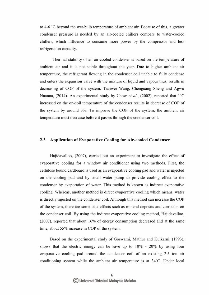
Thermal stability of an air-cooled condenser is based on the temperature of
ambient air and it is not stable throughout the year. Due to higher ambient air
temperature, the refrigerant flowing in the condenser coil unable to fully condense
and enters the expansion valve with the mixture of liquid and vapour thus, results in
decreasing of COP of the system. Tianwei Wang, Chenguang Sheng and Agwu
Nnanna, (2014). An experimental study by Chow et al., (2002), reported that 1˚C
increased on the on-coil temperature of the condenser results in decrease of COP of
the system by around 3%. To improve the COP of the system, the ambient air
temperature must decrease before it passes through the condenser coil.
2.3 Application of Evaporative Cooling for Air-cooled Condenser
Hajidavalloo, (2007), carried out an experiment to investigate the effect of
evaporative cooling for a window air conditioner using two methods. First, the
cellulose bound cardboard is used as an evaporative cooling pad and water is injected
on the cooling pad and by small water pump to provide cooling effect to the
condenser by evaporation of water. This method is known as indirect evaporative
cooling. Whereas, another method is direct evaporative cooling which means, water
is directly injected on the condenser coil. Although this method can increase the COP
of the system, there are some side effects such as mineral deposits and corrosion on
the condenser coil. By using the indirect evaporative cooling method, Hajidavalloo,
(2007), reported that about 16% of energy consumption decreased and at the same
time, about 55% increase in COP of the system.
Based on the experimental study of Goswami, Mathur and Kulkarni, (1993),
shows that the electric energy can be save up to 10% - 20% by using four
evaporative cooling pad around the condenser coil of an existing 2.5 ton air
conditioning system while the ambient air temperature is at 34˚C. Under local

7
condition, an indirect evaporative cooling system applied to packaged unit air
conditioner and they are able to improve the cooling load up to 75% and consume
55% less electrical energy. Delfani Shahram, (2010). Zhang et al., (2000), carried out
a study on the evaporative cooler permeated with corrugated holed aluminium foil
and given relationship to estimate the performance, pressure drop and outlet air
temperature of the cooler. They apply the relationship for estimate the enhancement
of an air-cooled chiller by analyze the exit temperature of evaporative cooler with the
performance curve of the chiller and conclude that the COP for chiller could be
enhanced about 39%. An air-cooled chiller coupled with a direct evaporative cooler
able to reduce 14.4% in power consumption and increase the refrigeration capacity
about 4.6%. Yu and Chan, (2005).
Chaktranond and Doungsong, (2010), carried out an experimental study on the
residential size split type air conditioner’s condensing unit retrofitted with an indirect
evaporative cooling system. The water injecting method on the evaporative cooling
pad divided into two types which is water curtain and water spray. The evaporative
cooling pad is placed in the upstream flow of air entering the condenser coil. The gap
between the condenser coil and the evaporative cooling pad is 0.05m. By using this
indirect evaporative cooling system, the ambient air temperature that entering the
condenser coil could be reduced up to 3˚C and conclude that the ambient air
temperature affects the system performances more than the relative humidity.
Figure 2.1: Schematic diagram of evaporative cooling system (Chaktranond and Doungsong, 2010)

8
2.4 Water Spray Mist Pre-Cooling System
According Hsieh and Yao, (2006), the water spray mist cooling system with a
tor or mesh material (WSMCST) is not a new concept because it have been applied
in various types of industries, but not common in air conditioning and refrigeration
system. This condenser performance enhancement method is differing from other
method due to this system monitored in real-time and electronically controlled. This
WSMCST system mainly consists of three subsystems such as water treatment and
control unit, high pressure pulverization unit with atomization nozzles and the third
is a specially manufactured microprocessor. An experimental study by Jia Yang et al.,
(2012), shows that the high pressure pump deliver water with 70 bar pressure and
forced through a micro nozzle to create a mist of 10µm droplets to produce a cloud
of very small water droplets. These droplets vaporized by the ambient air before get
in the condenser coil and the ambient air temperature reduced follow by the adiabatic
cooling process with constant specific enthalpy.
Jia Yang et al., (2012), reported that, this system does not cause any flow
obstructions to the air stream of the air-cooled condenser. It uses only a little amount
of electric energy to run the high pressure pump to form water mist. According to
Pongsakorn and Thepa, (2013), a study on the inverter air conditioning system tested
under multiple water spray rates and frequencies with three different temperature
scales in fixed ambient temperature. This study results in increase of COP by 35% at
a lower water spray rate of 100 L/h and a higher frequency of 80-90 Hz. Yu and
Chan, (2005), noticed that there is not enough research on the chillers which using
multiple compressors and good water mist generation under condenser temperature
control (CTC), the characteristic of dry-bulb temperature (DBT) and relative
humidity (%RH) of the ambient air which get in the condenser coil is the important
parameters to evaluate the thermal effectiveness of the water mist system.
9
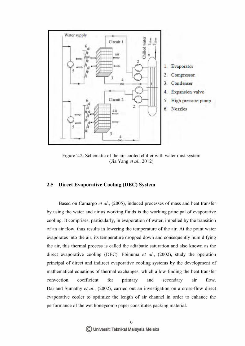
Figure 2.2: Schematic of the air-cooled chiller with water mist system (Jia Yang et al., 2012)
2.5 Direct Evaporative Cooling (DEC) System
Based on Camargo et al., (2005), induced processes of mass and heat transfer
by using the water and air as working fluids is the working principal of evaporative
cooling. It comprises, particularly, in evaporation of water, impelled by the transition
of an air flow, thus results in lowering the temperature of the air. At the point water
evaporates into the air, its temperature dropped down and consequently humidifying
the air, this thermal process is called the adiabatic saturation and also known as the
direct evaporative cooling (DEC). Ebinuma et al., (2002), study the operation
principal of direct and indirect evaporative cooling systems by the development of
mathematical equations of thermal exchanges, which allow finding the heat transfer
convection coefficient for primary and secondary air flow.
Dai and Sumathy et al., (2002), carried out an investigation on a cross-flow direct
evaporative cooler to optimize the length of air channel in order to enhance the
performance of the wet honeycomb paper constitutes packing material.