university of alberta aerial robotics...
TRANSCRIPT
2008 AUVSI Student UAS Competition
Journal Paper Submission
University of Alberta Aerial Robotics Group
May 28, 2008
2 University of Alberta Aerial Robotics Group
Abstract. This paper describes the 2008 foray of the University of Alberta Aerial Robotics Group into developing a complete unmanned aircraft system capable of safe and autonomous takeoff, flight manoeuvres, navigation, and landing, with acquisition and wireless relay of images to a ground station. Ultimately, the system can register acquired images to provide GPS coordinates for an object of interest specified by a human operator at the ground station.
Contents 1 Introduction .......................................................................................................................................... 3
2 Mission .................................................................................................................................................. 3
2.1 Approach ....................................................................................................................................... 3
2.2 Requirements ................................................................................................................................ 4
3 Systems ................................................................................................................................................. 5
3.1 Airframe ........................................................................................................................................ 7
3.1.1 Wing Design .......................................................................................................................... 7
3.1.2 Engine .................................................................................................................................... 9
3.1.3 Actuators ............................................................................................................................... 9
3.1.4 Cargo Bay ............................................................................................................................ 10
3.1.5 Electromagnetic Shielding ................................................................................................... 10
3.2 Onboard Electronics .................................................................................................................... 10
3.2.1 Autopilot ............................................................................................................................. 10
3.2.2 Airborne Communications .................................................................................................. 13
3.2.3 Onboard Computer ............................................................................................................. 14
3.2.4 Camera ................................................................................................................................ 15
3.2.5 Power Systems .................................................................................................................... 15
3.2.6 Failsafe and Redundant Control System ............................................................................. 16
3.3 Ground Station ............................................................................................................................ 17
3.3.1 Communications ................................................................................................................. 17
3.3.2 Computer ............................................................................................................................ 17
3.3.3 Software .............................................................................................................................. 18
4 Test Results & Future Considerations ................................................................................................. 19
5 Conclusion ........................................................................................................................................... 19
6 References .......................................................................................................................................... 20
3 University of Alberta Aerial Robotics Group
1 Introduction Growing maturity of unmanned aircraft systems (UAS) along with improving digital image capture technology is driving UAS development for battlefield use and, more recently, a variety of civilian applications. Private enterprise is starting to take up the charge, finding ways to leverage UAS strengths for missions in disaster mitigation, wildfire management, search and rescue, insurance, and forestry. Of prime importance to UAS success in all theatres of interest is autonomous control, navigation, and data collection. The AUVSI Student UAS Competition 2008 affords the University of Alberta Aerial Robotics Group (UAARG) a focus in developing a complete unmanned aircraft which aims to satisfy ambitious technical requirements. This paper describes UAARG’s entry for the 2008 competition, and how its team of undergraduate students approached this year’s challenges.
2 Mission
2.1 Approach It is UAARG’s goal to produce a vehicle which meets or exceeds all mandatory requirements for the 2008 UAS Competition.
To achieve a clear and simple overall system design, the team extracted requirements and specifications from the competition rules [1]. Doing so allowed all design teams to work towards a common goal. Discussion and cooperative design between the various design teams also aided in the realization of a workable and complete system.
Summarizing objectives and requirements also allowed the group to view the competition as a whole, and enabled selection of hardware and components capable of meeting desired objectives.
Since the design and construction of an unmanned system is not trivial, the team determined that it had insufficient resources to complete several optional mission objectives. These were set aside for future years; however, subsystems were designed and hardware selected to accommodate upgrades which will allow fulfillment of outstanding optional objectives in the future.
4 University of Alberta Aerial Robotics Group
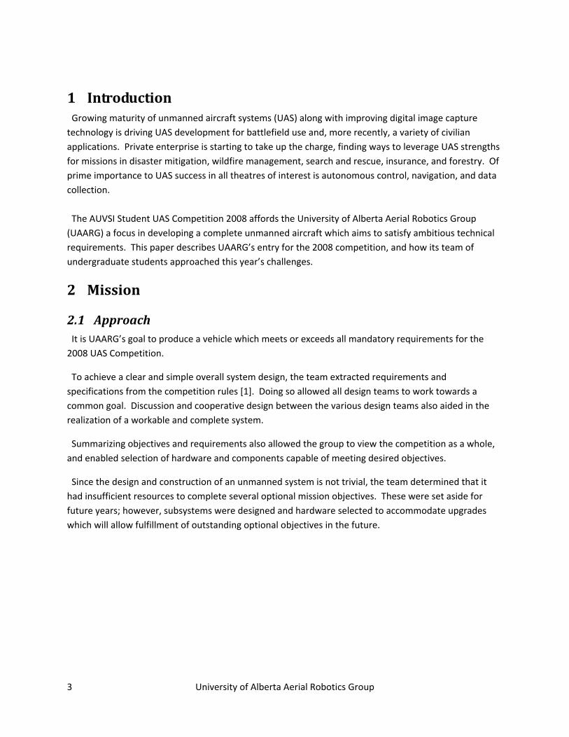
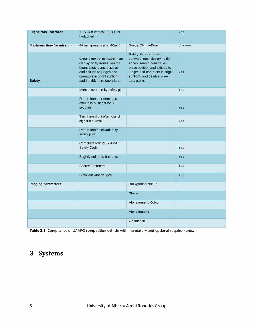
2.2 Requirements Requirements identified by UAARG are summarized in Table 2.1 below:
Competition Parameter Threshold (Mandatory) Objective (Optional) Compliance
Minimum altitude 30.48m MSL Governed
Maximum altitude 228.6m MSL Governed
Max air speed 100 KIAS Yes
Maximum weight of entire plane 24.947kg Yes
Land/Take off in crosswinds of 14.81km/hr, gusts 20.37 km/hr Yes
Fly in Winds of 27.78km/hr, gusts 37.04 km/hr Yes
Maximum environment temperature 43.33 degrees C Yes
Weather Fly in 2 mile with no precipitation Yes
Communication protocols JAUS No
Special target 1: High altitude 152.4 ± 15.24m Yes
Special target 2: Angled picture
76.2m away, at 60.96 ± 15.24m Unknown
Minimum size of target for imaging 2.4384m x 2.4384 (Square) 0.609m x 0.609m (Square) Unknown
Angle of camera Up to 60 degrees from vertical No
Alphanumeric thickness 0.4572m 0.1524m Unknown
Imaging Identify 2 parameters, display to judges
Identify all parameters autonomously Threshold
Target location Within 76.2m Within 15.24m Unknown
Real time actionable intelligence X Unknown
Autonomy Way point navigation and search Take off and landing Unknown
In-flight retasking Add waypoint Adjust search zone Yes
Real time flight changes Altitude, speed, direction Yes
5 University of Alberta Aerial Robotics Group
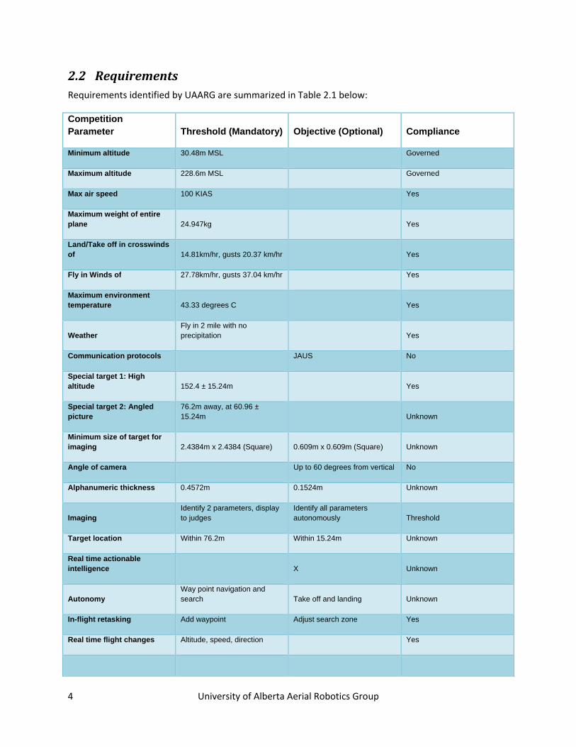
Flight Path Tolerance ± 15.24m vertical; ± 30.5m horizontal
Yes
Maximum time for mission 40 min (penalty after 40min) Bonus: 20min-40min Unknown
Safety:
Ground control software must display no fly-zones, search boundaries, plane position and altitude to judges and operators in bright sunlight, and be able to re-task plane.
Safety: Ground control software must display no fly-zones, search boundaries, plane position and altitude to judges and operators in bright sunlight, and be able to re-task plane.
Yes
Manual override by safety pilot Yes
Return home or terminate after loss of signal for 30 seconds Yes
Terminate flight after loss of signal for 3 min Yes
Return home activation by safety pilot
Compliant with 2007 AMA Safety Code Yes
Brightly-coloured batteries Yes
Secure Fasteners Yes
Sufficient wire gauges Yes
Imaging parameters: Background colour
Shape
Alphanumeric Colour
Alphanumeric
Orientation
Table 2.1: Compliance of UAARG competition vehicle with mandatory and optional requirements.
3 Systems
6 University of Alberta Aerial Robotics Group
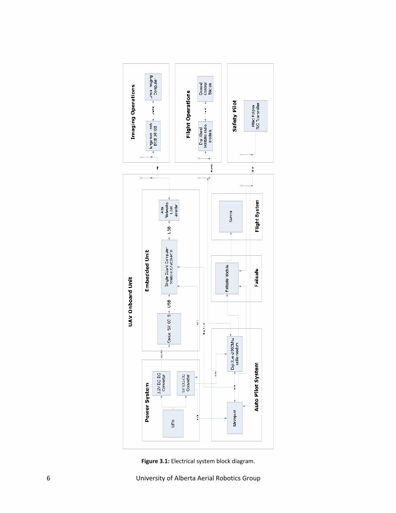
Figure 3.1: Electrical system block diagram.
7 University of Alberta Aerial Robotics Group
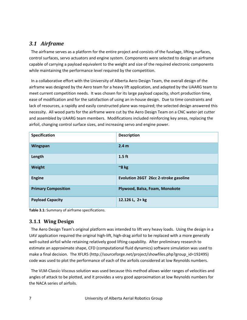
3.1 Airframe The airframe serves as a platform for the entire project and consists of the fuselage, lifting surfaces, control surfaces, servo actuators and engine system. Components were selected to design an airframe capable of carrying a payload equivalent to the weight and size of the required electronic components while maintaining the performance level required by the competition.
In a collaborative effort with the University of Alberta Aero Design Team, the overall design of the airframe was designed by the Aero team for a heavy lift application, and adapted by the UAARG team to meet current competition needs. It was chosen for its large payload capacity, short production time, ease of modification and for the satisfaction of using an in‐house design. Due to time constraints and lack of resources, a rapidly and easily constructed plane was required; the selected design answered this necessity. All wood parts for the airframe were cut by the Aero Design Team on a CNC water‐jet cutter and assembled by UAARG team members. Modifications included reinforcing key areas, replacing the airfoil, changing control surface sizes, and increasing servo and engine power.
Specification Description
Wingspan 2.4 m
Length 1.5 ft
Weight ~8 kg
Engine Evolution 26GT 26cc 2‐stroke gasoline
Primary Composition Plywood, Balsa, Foam, Monokote
Payload Capacity 12.126 L, 2+ kg
Table 3.1: Summary of airframe specifications.
3.1.1 Wing Design The Aero Design Team’s original platform was intended to lift very heavy loads. Using the design in a UAV application required the original high‐lift, high‐drag airfoil to be replaced with a more generally well‐suited airfoil while retaining relatively good lifting capability. After preliminary research to estimate an approximate shape, CFD (computational fluid dynamics) software simulation was used to make a final decision. The XFLR5 (http://sourceforge.net/project/showfiles.php?group_id=192495) code was used to plot the performance of each of the airfoils considered at low Reynolds numbers.
The VLM‐Classic‐Viscous solution was used because this method allows wider ranges of velocities and angles of attack to be plotted, and it provides a very good approximation at low Reynolds numbers for the NACA series of airfoils.
8 University of Alberta Aerial Robotics Group
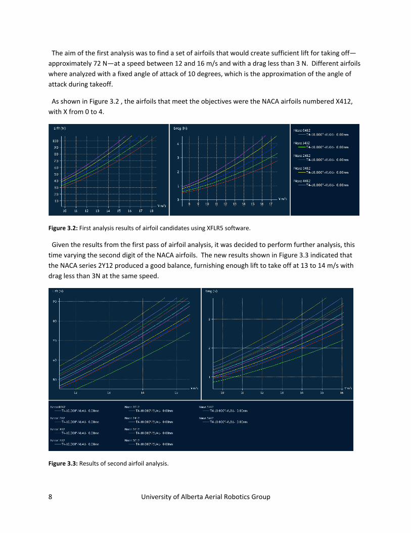
The aim of the first analysis was to find a set of airfoils that would create sufficient lift for taking off— approximately 72 N—at a speed between 12 and 16 m/s and with a drag less than 3 N. Different airfoils where analyzed with a fixed angle of attack of 10 degrees, which is the approximation of the angle of attack during takeoff.
As shown in Figure 3.2 , the airfoils that meet the objectives were the NACA airfoils numbered X412, with X from 0 to 4.
Figure 3.2: First analysis results of airfoil candidates using XFLR5 software.
Given the results from the first pass of airfoil analysis, it was decided to perform further analysis, this time varying the second digit of the NACA airfoils. The new results shown in Figure 3.3 indicated that the NACA series 2Y12 produced a good balance, furnishing enough lift to take off at 13 to 14 m/s with drag less than 3N at the same speed.
Figure 3.3: Results of second airfoil analysis.
9 University of Alberta Aerial Robotics Group
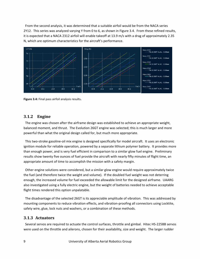
From the second analysis, it was determined that a suitable airfoil would be from the NACA series 2Y12. This series was analyzed varying Y from 0 to 6, as shown in Figure 3.4. From these refined results, it is expected that a NACA 2312 airfoil will enable takeoff at 13.9 m/s with a drag of approximately 2.35 N, which are optimum characteristics for the aircraft’s performance.
Figure 3.4: Final pass airfoil analysis results.
3.1.2 Engine The engine was chosen after the airframe design was established to achieve an appropriate weight, balanced moment, and thrust. The Evolution 26GT engine was selected; this is much larger and more powerful than what the original design called for, but much more appropriate.
This two‐stroke gasoline‐oil mix engine is designed specifically for model aircraft. It uses an electronic ignition module for reliable operation, powered by a separate lithium polymer battery. It provides more than enough power, and is very fuel efficient in comparison to a similar glow fuel engine. Preliminary results show twenty five ounces of fuel provide the aircraft with nearly fifty minutes of flight time, an appropriate amount of time to accomplish the mission with a safety margin.
Other engine solutions were considered, but a similar glow engine would require approximately twice the fuel (and therefore twice the weight and volume). If the doubled fuel weight was not deterring enough, the increased volume for fuel exceeded the allowable limit for the designed airframe. UAARG also investigated using a fully electric engine, but the weight of batteries needed to achieve acceptable flight times rendered this option unpalatable.
The disadvantage of the selected 26GT is its appreciable amplitude of vibration. This was addressed by mounting components to reduce vibration effects, and vibration‐proofing all connectors using Locktite, safety wire, glue, lock nuts and washers, or a combination of these methods.
3.1.3 Actuators Several servos are required to actuate the control surfaces, throttle and gimbal. Hitec HS‐225BB servos were used on the throttle and ailerons, chosen for their availability, size and weight. The larger rudder
10 University of Alberta Aerial Robotics Group
and elevator surfaces were outfitted with high torque Hitec HS‐755 servos to handle the greater loading. The camera gimbal is actuated using two small Hitec HS‐81 servos which, while very small and lightweight, provide sufficient torque to move the camera.
3.1.4 Cargo Bay The payload of the aircraft is contained primarily in the central part of the fuselage. A wooden mounting structure, supplemented by vibration‐dampening latex foam and hardware, is used to attach components inside the payload bay. The camera gimbal is integrated into the fuselage, and was built to be dimensionally minimal and lightweight while still having enough capability to allow the camera to obtain an image of the offset target, as described by the competition.
3.1.5 Electromagnetic Shielding Cursory testing revealed that on‐board electronic components were adversely affected by stray electromagnetic radiation from other platform components (such as the engine when operating). Consequently, shielding key components and areas was accomplished by using very thin, lightweight aluminum which is connected to the system ground. The shielding successfully protects various payload components from radio frequency interference coming from the engine ignition, radio transmitters, servos and power sources.
3.2 Onboard Electronics
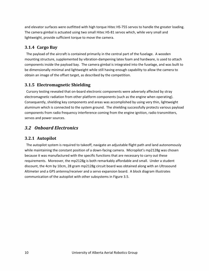
3.2.1 Autopilot The autopilot system is required to takeoff, navigate an adjustable flight path and land autonomously while maintaining the constant position of a down‐facing camera. Micropilot’s mp2128g was chosen because it was manufactured with the specific functions that are necessary to carry out these requirements. Moreover, the mp2128g is both remarkably affordable and small. Under a student discount, the 4cm by 10cm, 28 gram mp2128g circuit board was obtained along with an Ultrasound Altimeter and a GPS antenna/receiver and a servo expansion board. A block diagram illustrates communication of the autopilot with other subsystems in Figure 3.5.
11 University of Alberta Aerial Robotics Group
Figure 3.5: MP2128 autopilot interaction with other subsystems. [2]
The mp2128g comprises a system of flight instruments, sensors, and PID loops that control external servos with the objective of maintaining stable flight while carrying out a sequence of commands which are received from the GCS or RC controller. Amongst the flight instruments are a total of five sensors, a GPS receiver/antenna, and an ultrasonic high resolution altimeter (only used during takeoff and landing). There are twelve PID loops allocated to flying and eight user‐defined PID loops (three of which are used to stabilize the ground facing camera against pitch, yaw and roll) onboard the mp2128g. The sensors and instruments on the mp2128g include a set of 3‐axis gyros, a pressure altimeter, and airspeed sensor. The mp2128g communicates with its GCS using radio modems attached via RS232 connectors. Comparatively, the RC receiver is connected directly to the mp2128g circuit board.
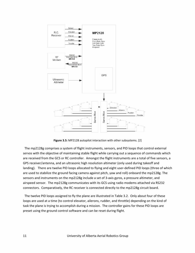
The twelve PID loops assigned to fly the plane are illustrated in Table 3.2. Only about four of these loops are used at a time (to control elevator, ailerons, rudder, and throttle) depending on the kind of task the plane is trying to accomplish during a mission. The controller gains for these PID loops are preset using the ground control software and can be reset during flight.
12 University of Alberta Aerial Robotics Group
Name Controls Description
0 aileron from roll aileron Minimizes difference between desired and actual roll
1 elevator from pitch elevator Minimizes difference between desired and actual pitch
2 rudder from Y accelerometer
rudder Minimizes difference between desired and actual Y accelerometer values; coordinates turns
3 rudder from heading
rudder Minimizes difference between desired and actual heading; heading coordination during takeoff
4 throttle from speed
throttle Minimizes difference between desired and actual speed; used in final approach when speed is controlled by throttle and altitude by elevator
5 throttle from altitude
throttle Minimizes difference between desired and actual altitude; used when controlling altitude via throttle and speed via elevator
6 pitch from altitude desired pitch Minimizes difference between desired and actual altitude
7 pitch from AGL desired pitch Minimizes difference between desired and actual altitude as measured by the AGL board; controls the flare during landing
8 pitch from airspeed desired pitch
Minimizes difference between desired and actual airspeed; used during climb and level flight when controlling altitude via throttle
9 roll from heading desired roll Minimizes difference between desired and actual heading; used any time
autopilot is navigating
10 heading from crosstrack error desired heading Minimizes distance between aircraft and the line running from the previous
waypoint to the next; used when running the fromTo command
11 pitch from descent desired pitch Minimizes difference between desired and actual descent rate
Table 3.2: PID loops with the mp2128g (adapted from reference [2]).
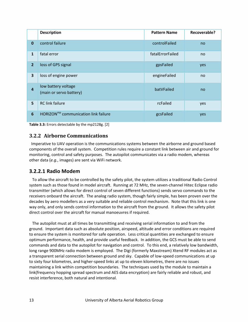
The mp2128g detects a total of seven errors shown in Table 3.3, three of which are considered unrecoverable. The pattern of commands to be engaged under in the event of an error are programmed from the GCS and loaded onto the autopilot. Unrecoverable error commands are final while recoverable error commands can be terminated when the error no longer exists. The autopilot has been set to quit its mission and return home (i.e., to land at its take off position) on any link failure that lasts for more than 30 seconds but to terminate the flight and shut the throttle, set the elevator, ailerons and rudder to full up, full right and full right, respectively on a loss of GPS signal or a link failure for up to 3 minutes.
13 University of Alberta Aerial Robotics Group
Description Pattern Name Recoverable?
0 control failure controlFailed no
1 fatal error fatalErrorFailed no
2 loss of GPS signal gpsFailed yes
3 loss of engine power engineFailed no
4 low battery voltage (main or servo battery)
batVFailed no
5 RC link failure rcFailed yes
6 HORIZONmp communication link failure gcsFailed yes
Table 3.3: Errors detectable by the mp2128g. [2]
3.2.2 Airborne Communications Imperative to UAV operation is the communications systems between the airborne and ground based components of the overall system. Competition rules require a constant link between air and ground for monitoring, control and safety purposes. The autopilot communicates via a radio modem, whereas other data (e.g., images) are sent via WiFi network.
3.2.2.1 Radio Modem To allow the aircraft to be controlled by the safety pilot, the system utilizes a traditional Radio Control system such as those found in model aircraft. Running at 72 MHz, the seven‐channel Hitec Eclipse radio transmitter (which allows for direct control of seven different functions) sends servo commands to the receivers onboard the aircraft. The analog radio system, though fairly simple, has been proven over the decades by aero modellers as a very suitable and reliable control mechanism. Note that this link is one way only, and only sends control information to the aircraft from the ground. It allows the safety pilot direct control over the aircraft for manual manoeuvres if required. The autopilot must at all times be transmitting and receiving serial information to and from the ground. Important data such as absolute position, airspeed, altitude and error conditions are required to ensure the system is monitored for safe operation. Less critical quantities are exchanged to ensure optimum performance, health, and provide useful feedback. In addition, the GCS must be able to send commands and data to the autopilot for navigation and control. To this end, a relatively low bandwidth, long range 900MHz radio modem is employed. The Digi (formerly Maxstream) Xtend RF modules act as a transparent serial connection between ground and sky. Capable of low‐speed communications at up to sixty four kilometres, and higher‐speed links at up to eleven kilometres, there are no issues maintaining a link within competition boundaries. The techniques used by the module to maintain a link(frequency hopping spread spectrum and AES data encryption) are fairly reliable and robust, and resist interference, both natural and intentional.
14 University of Alberta Aerial Robotics Group
3.2.2.2 WiFi Network The onboard image capture also requires a means of data transfer. A two way link is required in this situation as well, with the primary focus being the air to ground data flow. A small amount of command information is sent from the imaging ground control unit to the onboard imaging system, while a very large amount of data, primarily image files, is sent from the aircraft to the ground computer. The method used in this situation is that of a standard 802.11b wireless network. The imaging computer onboard the aircraft has more than enough capability to manage and interface with a high‐powered USB wireless network adapter. The Alfa Networks device is a relatively high sensitivity/high‐power device. A low‐gain, omni‐directional antenna is used on the module to limit directional bias and ensure similar sensitivity of transmittance and reception at varying aircraft attitudes and orientations. As with all 802.11 networks, there is built‐in data encryption support to reduce intentional eavesdropping or disruption of the system. The device is also perfectly compatible with the Linux operating system used for image capture.
The inherent nature of the WiFi network allows the system to be fairly flexible. At close ranges, high data rates are possible, while at greater distances, the link may become noticeably degraded. The system dynamically accounts for these changes to accommodate varying performance conditions. Software implemented buffers also allow for changing data rates, storing unsent data when bandwidth is low, and correcting for it when bandwidth is high. The decision to pursue the WiFi standard had more than one advantage: the equipment used in the link is relatively cheap and easily accessible off‐the‐shelf, in comparison to other data protocols and frequencies; additionally, one of the optional requirements, the JAUS compliance, utilizes a similar network structure. Therefore, the system may be upgraded in the future to provide this functionality.
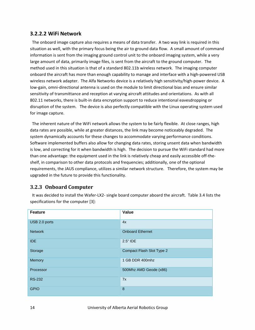
3.2.3 Onboard Computer It was decided to install the Wafer‐LX2‐ single board computer aboard the aircraft. Table 3.4 lists the specifications for the computer [3]:
Feature Value
USB 2.0 ports 4x
Network Onboard Ethernet
IDE 2.5” IDE
Storage Compact Flash Slot Type 2
Memory 1 GB DDR 400mhz
Processor 500Mhz AMD Geode (x86)
RS-232 7x
GPIO 8
15 University of Alberta Aerial Robotics Group
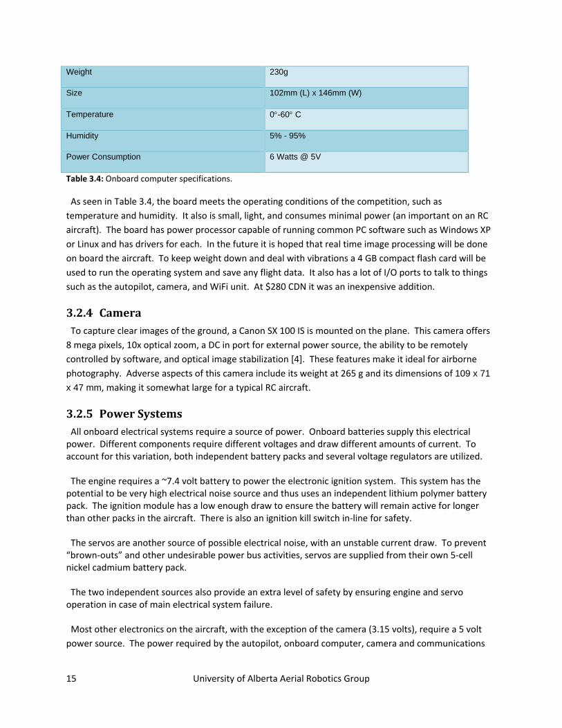
Weight 230g
Size 102mm (L) x 146mm (W)
Temperature 0°-60° C
Humidity 5% - 95%
Power Consumption 6 Watts @ 5V
Table 3.4: Onboard computer specifications.
As seen in Table 3.4, the board meets the operating conditions of the competition, such as temperature and humidity. It also is small, light, and consumes minimal power (an important on an RC aircraft). The board has power processor capable of running common PC software such as Windows XP or Linux and has drivers for each. In the future it is hoped that real time image processing will be done on board the aircraft. To keep weight down and deal with vibrations a 4 GB compact flash card will be used to run the operating system and save any flight data. It also has a lot of I/O ports to talk to things such as the autopilot, camera, and WiFi unit. At $280 CDN it was an inexpensive addition.
3.2.4 Camera To capture clear images of the ground, a Canon SX 100 IS is mounted on the plane. This camera offers 8 mega pixels, 10x optical zoom, a DC in port for external power source, the ability to be remotely controlled by software, and optical image stabilization [4]. These features make it ideal for airborne photography. Adverse aspects of this camera include its weight at 265 g and its dimensions of 109 x 71 x 47 mm, making it somewhat large for a typical RC aircraft.
3.2.5 Power Systems All onboard electrical systems require a source of power. Onboard batteries supply this electrical power. Different components require different voltages and draw different amounts of current. To account for this variation, both independent battery packs and several voltage regulators are utilized. The engine requires a ~7.4 volt battery to power the electronic ignition system. This system has the potential to be very high electrical noise source and thus uses an independent lithium polymer battery pack. The ignition module has a low enough draw to ensure the battery will remain active for longer than other packs in the aircraft. There is also an ignition kill switch in‐line for safety. The servos are another source of possible electrical noise, with an unstable current draw. To prevent “brown‐outs” and other undesirable power bus activities, servos are supplied from their own 5‐cell nickel cadmium battery pack. The two independent sources also provide an extra level of safety by ensuring engine and servo operation in case of main electrical system failure. Most other electronics on the aircraft, with the exception of the camera (3.15 volts), require a 5 volt power source. The power required by the autopilot, onboard computer, camera and communications
16 University of Alberta Aerial Robotics Group
equipment is fairly substantial. A high capacity lithium polymer battery pack is connected to two independent voltage regulators, one set to supply five volts and the other to supply 3.2 volts. Each high‐efficiency switching supply can provide up to 55 watts (well under the required amount) and has integrated under‐voltage lock‐out protection to ensure the lithium pack does not fall below 3.0 volts per cell. This ensures safe operation of the batteries which, if treated incorrectly, can pose a fire hazard, as does any other source of power or fuel— electrical, petroleum‐based, or otherwise. Wiring harnesses and switches compose the rest of the power source. High performance Deans Ultra connectors are used in most places, as they are secure, can handle very high currents and are easy to connect and disconnect.
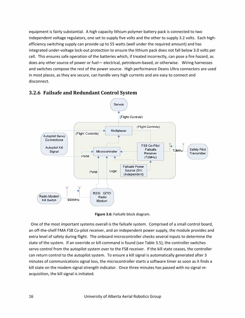
3.2.6 Failsafe and Redundant Control System
Figure 3.6: Failsafe block diagram.
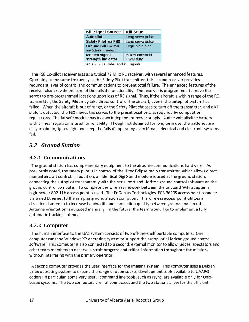
One of the most important systems overall is the failsafe system. Comprised of a small control board, an off‐the‐shelf FMA FS8 Co‐pilot receiver, and an independent power supply, the module provides and extra level of safety during flight. The onboard microcontroller checks several inputs to determine the state of the system. If an override or kill command is found (see Table 3.5), the controller switches servo control from the autopilot system over to the FS8 receiver. If the kill state ceases, the controller can return control to the autopilot system. To ensure a kill signal is automatically generated after 3 minutes of communications signal loss, the microcontroller starts a software timer as soon as it finds a kill state on the modem signal strength indicator. Once three minutes has passed with no signal re‐acquisition, the kill signal is initiated.
17 University of Alberta Aerial Robotics Group
Kill Signal Source Kill State Autopilot Long servo pulse Safety Pilot via FS8 Long servo pulse Ground Kill Switch via Xtend modem
Logic state high
Modem signal strength indicator
Below threshold PWM duty
Table 3.5: Failsafes and kill signals.
The FS8 Co‐pilot receiver acts as a typical 72 MHz RC receiver, with several enhanced features. Operating at the same frequency as the Safety Pilot transmitter, this second receiver provides redundant layer of control and communications to prevent total failure. The enhanced features of the receiver also provide the core of the failsafe functionality. The receiver is programmed to move the servos to pre‐programmed locations upon loss of RC signal. Thus, if the aircraft is within range of the RC transmitter, the Safety Pilot may take direct control of the aircraft, even if the autopilot system has failed. When the aircraft is out of range, or the Safety Pilot chooses to turn off the transmitter, and a kill state is detected, the FS8 moves the servos to the preset positions, as required by competition regulations. The failsafe module has its own independent power supply. A nine volt alkaline battery with a linear regulator is used for reliability. Though not designed for long term use, the batteries are easy to obtain, lightweight and keep the failsafe operating even if main electrical and electronic systems fail.
3.3 Ground Station
3.3.1 Communications The ground station has complementary equipment to the airborne communications hardware. As previously noted, the safety pilot is in control of the Hitec Eclipse radio transmitter, which allows direct manual aircraft control. In addition, an identical Digi Xtend module is used at the ground station, connecting the autopilot transparently with the serial port and Horizon ground control software on the ground control computer. To complete the wireless network between the onboard WiFi adapter, a high‐power 802.11b access point is used. The EnGenius Technologies ECB 3610S access point connects via wired Ethernet to the imaging ground station computer. This wireless access point utilizes a directional antenna to increase bandwidth and connection quality between ground and aircraft. Antenna orientation is adjusted manually. In the future, the team would like to implement a fully automatic tracking antenna.
3.3.2 Computer The human interface to the UAS system consists of two off‐the‐shelf portable computers. One computer runs the Windows XP operating system to support the autopilot’s Horizon ground control software. This computer is also connected to a second, external monitor to allow judges, spectators and other team members to observe aircraft progress and critical information throughout the mission, without interfering with the primary operator. A second computer provides the user interface for the imaging system. This computer uses a Debian Linux operating system to expand the range of open source development tools available to UAARG coders; in particular, some very useful command line tools, such as rsync, are available only for Unix‐based systems. The two computers are not connected, and the two stations allow for the efficient
18 University of Alberta Aerial Robotics Group
distribution of system control tasks, as well as separating critical control and non‐critical payload parts of the interface.
3.3.3 Software
3.3.3.1 Control Horizon is the standard ground control software for the mp2128g autopilot. It is used for simulation, control, and in‐flight monitoring of the autopilot and by extension, the UAS. Horizon is used to program waypoints, flight patterns, controller gains, threads and activity schedules for the autopilot. The set of waypoints and controller gains can be adjusted during flight.
Monitoring is achieved by the use of a latitude‐longitude grid (over which a map can be superimposed) and an icon representing the UAS which moves across the map as the plane flies across the ground. Horizon receives telemetry and other critical information from the autopilot at 5 Hz. This telemetry is stored on the hard disk from which Horizon is running.
3.3.3.2 Imaging To acquire the location of a target in the search zone requires several software processes. The UAS must first collect the required information using an onboard computer. It is then transferred to the ground where the ground station software can analyze it. This is a complex task.
To handle the photography and telemetry acquisition a custom program written in C++ is used. This program runs on the onboard computer. First the program calculates when to take a picture using the current UAS altitude, speed and camera zoom. When it is time to take a picture, the program collects telemetry such as GPS, altitude, and speed by sniffing the serial port between the autopilot and radio modem. Next a picture is taken using the Canon “capture” [5] program. This program allows the camera to be controlled by the onboard computer so that various camera settings such as zoom, resolution, and shutter speed can be configured. When the calculated time arrives the onboard software calls the Canon capture software, adjusts the camera settings, and then takes a picture.
The telemetry data and the image are saved on a RAM disk on the onboard computer. A RAM disk is used because saving the data to a compact flash card is too slow. The data is copied from the RAM disk down to the ground station by using rsync over the WiFi connection. rsync is an efficient program and can transmit just the differences between files. This is useful in the event that the onboard computer briefly loses its connection to the ground, as it can then use the bandwidth available most efficiently.
The Linux ground station now processes the images and telemetry data. ImageMagick [6] will execute basic image transforms, such as normalizing the photograph based on altitude. The originals are saved in one folder with the normalized photos in another. Next, the normalized photos are opened using custom ground software written with QT [7]. The software presents the operator with the photographs and the operator can then scan them for targets. Once the operator finds a target of interest they can click on it. The software then uses the telemetry data to return the GPS coordinates of the object shown
19 University of Alberta Aerial Robotics Group
on the screen by converting pixel coordinates to GPS coordinates. Images of interest can be bookmarked for further analysis at a later time.
4 Test Results & Future Considerations The testing and evaluation of the team’s system is an iterative, open‐ended and continuing process. Testing and optimization is ongoing and will continue beyond the competition. The team hopes to enhance and upgrade the current system for future competitions and as a test‐bed for future developments. Preliminary testing has been performed on most systems, though changes continue to be made to ensure optimum performance.
Autopilot performance has not been explored to its full potential, and its capabilities will not be fully utilized this year. It is noteworthy that the Micropilot system’s relative ease of use, as well as its ability to be almost fully customized, shows the decision to use the device was justified.
The imaging system has not been fully integrated, though initial testing at a very basic level shows promise for capabilities which are enough to accomplish competition threshold objectives. The design is inherently adaptable and upgradeable, and thus, future additions and upgrades will include autonomous image recognition and better performance.
The airframe, custom designed and built as a collaborative effort between student teams at the University of Alberta, has proven to be a suitable and effective platform for the project. Flight characteristics are favourable for autopilot and manual control, and the aircraft has few, if any, undesirable tendencies. The aircraft has shown itself to be capable of handling competition wind conditions of approximately 30 km/h on a grass runway.
5 Conclusion The University of Alberta Aerial Robotics Group has entered a team into the 2008 AUVSI Student UAS Competition, and successfully built an autonomous airborne reconnaissance system capable of achieving competition objectives. The airborne platform was designed and built in‐house as a fixed‐wing aircraft with the capacity to carry the required payload. Autonomous control was achieved using a Micropilot autopilot, a proven, economical and easily integrated solution. The image acquisition system utilized a small onboard computer, together with a Canon digital still camera, and a combination of custom open source software. An 802.11b wireless network enabled imaging payload communication with operators on the ground, while a long range serial connection kept the autopilot in contact with its corresponding ground control station and operators. With safety being a primary concern, a dedicated failsafe module was also included. While not all desired testing and optimization has been completed at the present writing, system performance was seen to be adequate in light of the team’s 2008 goals. The group hopes to take the current design, and build upon its flexible and upgradeable architecture in future years.
20 University of Alberta Aerial Robotics Group
6 References [1] “2007 UAV Student Competition,” 4‐2008; http://www.navair.navy.mil/pma263/seafarers/rules/rules_2008Final.pdf.
[2] “Micropilot autopilot installation and operation” Micropilot Inc., 5‐2008.
[3] “IEI Technology Corp. – Industrial PC – SBC – WAFER‐LX2,” 4‐2008;
[4] “Canon Canada Inc, ‐ Products,” 5‐2008; http://www.canon.ca/english/index‐products.asp?lng=en&prodid=1246&sgid=23&gid=2&ovr=1&epage=specifications
[5] “Canon capture,” 5‐2008; http://capture.sourceforge.net/
[6] “ImageMagic: Convert, Edit, and Compose Images,” 5‐2008; http://www.imagemagick.org/script/index.php
[7] “Qt Cross‐Platform Application Framework,” 5‐2008;
http://trolltech.com/products/qt