university of alberta f ormula sae on- boarding package...
TRANSCRIPT

University of Alberta Formula SAE On-
Boarding Package 2011-2012

Preface
The purpose of this document is to provide a starting point for first time Formula SAE members. View it
as an introduction to Formula SAE. It obviously cannot answer all of the questions that come up but it
will offer enough information to get you started, and provide insight as to where more information may
be found. If you have questions while reading this, write them down and ask us to explain!
The topics discussed are:
Introduction 1. What is Formula FSAE
2. Putting it in perspective
3. Why do you want to be involved
4. Where do first year members fit in
Structure of Formula SAE 1. Executives and their roles
2. 2011-2012 year at a glance
Components & Systems within the Car 1. Cooling System
2. Steering & Pedals
3. Hubs & Uprights
4. Engine Selection
5. Brakes
6. Electronics & ECU
7. Suspension
8. Chassis
9. Fuel System
10. Drive Train
11. Body Panels
Frequently Asked Questions
Appendix A: Related Links

Introduction 1. What is Formula FSAE
2. Putting it in perspective
3. Why do you want to be involved
4. Where do first year members fit in
1. What is Formula SAE
Formula SAE (FSAE) is an off shoot from its parent organization SAE International (formerly SAE), an
engineering group responsible for regulating the aerospace and automotive industries. SAE hosts
several collegiate competitions namely Formula, Baja, Aero Design, Clean Snowmobile Challenge,
Hybrid, and Super mileage.
For information regarding
SAE as an organization see link 5 in Appendix A
SAE student competitions see link 6 in Appendix A
FSAE as defined by SAE see link 7 in Appendix A
The Formula SAE competition is held annually in two locations within North America: Nebraska (FSAE
Lincoln), and Michigan (FSAE Michigan). FSAE Lincoln will likely see 80 international student teams while
FSAE Michigan accepts 120, all vying for that first place trophy. There are many overseas FSAE
competitions which host 450+ teams worldwide. While at competition, teams are judged in several
categories which are organized into Static and Dynamic events:
Static Events
Design report
Cost report
Business case presentation
Dynamic Events
Acceleration
Autocross
Skidpad
Endurance
Fuel Economy
For more information on this list, see page 3 of the 2011 Event Guide posted in Appendix A and Parts C
& D in the 2011 FSAE Rules, also in Appendix A.

2. Putting it in perspective
To gain some perspective on the scale of this competition, a handful of pictures are posted below.
Also, check out this video! http://www.youtube.com/RaceLABtv#p/u/1/_g-PSVyyj-g
Oregon State Oklahoma State
University of Kansas Lawrence San Jose State
Missouri S&T USF

3. Why do you want to be involved
FSAE hits a sweet spot in the engineering world. It offers students a chance to design a world class car,
build it themselves and then race against other teams. It delivers on all of the niceties that every
engineering student loves: high revving engines, screeching tires, the smell of exhaust, and lots of shiny
carbon fibre components. More to the point, FSAE is a resume booster for young professionals. It
builds skills that employers are looking for. Additionally it is a great venue to meet like-minded
individuals.
The intensity of competition is very high, demanding the best from students. And because we all know
that a great challenge brings great satisfaction, the more you put into FSAE, the more you will get out.
That being said, FSAE needs individuals who are committed, who are innovative, and who have a strong
passion for excellence (and for winning competitions!).
4. Where do first year members fit in?
Members who join the team for the first time will participate primarily in building the car. They work
closely with the senior members in completing all of the tasks associated with the build. The purpose of
this ‘initiation’ is to show students all of the components of the car, fabrication techniques (what tools
we have at our disposal), how all the pieces come together, and how the team functions at the ground
level. The FSAE team is also planning on holding several seminars throughout the year. These will teach
new students the ins and outs of the car so that lessons learnt can be passed on to new members. All
that being said, your first year will be what you make it; there is lots to learn and lots of opportunities to
get involved on a technical level (you are not limited to just building the car). This first year is intended
to pique the student’s interest and direct them towards components which they may want to design in
their future years with the team. To succeed within Formula SAE, students must be eager to learn and
willing to put in long hours when required.
Structure of Formula SAE 1. Executives and their roles
2. 2011-2012 year at a glance
1. Executives and their roles
The majority of this information is held on the team’s website (See
http://www.ualbertafsae.com/?page_id=35), but for the sake of completion the list below outlines the
current executive team members and how to contact them. For information on their roles, see the link
cited above.

Team Lead
o Benjamin Dwyer
o Shawn Stevenson
Fabrication Lead
o Justin Bekker
Design Lead
o Gerard Reynolds
External Relations
o Anthony Stielow
Treasurer
o Charles Zoleta
Technical Advisor
o Brian Wagner
2. 2011-2012 year at a glance
Below is a rough outline/calendar for a full year with Formula SAE.
Design and Procurement Stage
Sept. 9th Concept finalization
Sept. 30th Design mid point, start detailed analysis
Oct. 21st Design review
Oct. 22nd Design Review
Oct. 28th Design Review
Nov. 1st Start drawings & cost report
Nov. 10th Internal drawing review
Nov. 17th Internal drawing review & cost review
Nov. 24th Critical design review with the Mec E department
Dec. 5th Cost review
Dec. 9th Design report review

Jan. 6th Cost finalized
Jan 7th Design report finished & first work session
Fabrication and Testing Stage
Jan. 7th Chassis mold prep, A-Arm and push rod construction, begin gas tank construction
Jan. 14th Chassis mold prep, cut and fit core material/carbon/mold release, weld push rods
Jan. 21st Lay up chassis, start building air intake, heat treat push rods/ A-Arms, mold prep for
seat/firewall
Jan. 28th Lay up chassis, press in sphericals, intake mold prep., seat/firewall layup
Feb. 4th Trim chassis, fit front/main roll hoops, seat/firewall trimming, mount tires
Feb. 11th Bond chassis/finish trimming, assemble hubs & uprights/pedals/diff & diff mount
Feb. 18th Start final assembly (instal engine, suspension, and steering), rolling chassis by this date, finish
pedal assembly
Feb. 25th Electronics complete, rad. fit up/welding, finish fuel tank/steering, instal pedals
Mar. 3rd Finish rad, fuel lines, brake lines, seat belts,steering wheel layup
Mar. 10th Clutch/shifting system, finish wiring harness, chain gaurd,install intake/throttle cable
Mar. 17th Install sensors, trim & install steering wheel
Mar. 31st Drivable car, testing stage commences
Mar. 31st – June Car testing and fine tuning
June 20th Formula SAE Lincoln (competition!)
Aug. (Date TBA) Western Canadian Shootout. A fun competition hosted by the UofC’s Schulich Racing
Team.
Aug. (Date TBA) Formula Student Germany. The FSAE team is discussing whether or not we should
compete with our car in Germany.
Aug. ~20th The cycle continues! A new car is underway as the design tasks are split up and team goals
are assesed.

Components & Systems within the Car All components below are designed for minimal weight and ease of manufacture. Also, care is taken to
ensure the center of mass of the car is kept centered and low to the ground. Designs must adhere to
the rules outlined in the FSAE rules (See the 2011 FSAE rules in Appendix A).
Constraints listed below should be taken with a grain of salt; these were stipulations that the 2010-2011
design team placed on themselves. Ultimately we will design a world class car through the most
appropriate avenues; there are unlimited ways to solve a problem and the pictures presented below
should not be viewed as the only method. Do not let the photos hinder your creative mind! They are
simply introductions to the car’s main components.
In no particular order:
1. Cooling System
2. Steering & Pedals
3. Hubs & Uprights
4. Engine Selection
5. Brakes
6. Electronics & ECU
7. Suspension
8. Chassis
9. Fuel System
10. Drive Train
11. Body Panels

1. Cooling System
The cooling system is located towards the back of the car, integrated into the engine package. It
provides the cooling needed to run the engine hard for a day of racing.
The primary design considerations are the fluid flow/properties of air and water.
‘Heat Transfer’ by Cengel is a good resource for this component as well as other textbooks covering heat
exchangers and fluid flow.
Custom Radiator Unit
Radiator Side-pod Housing
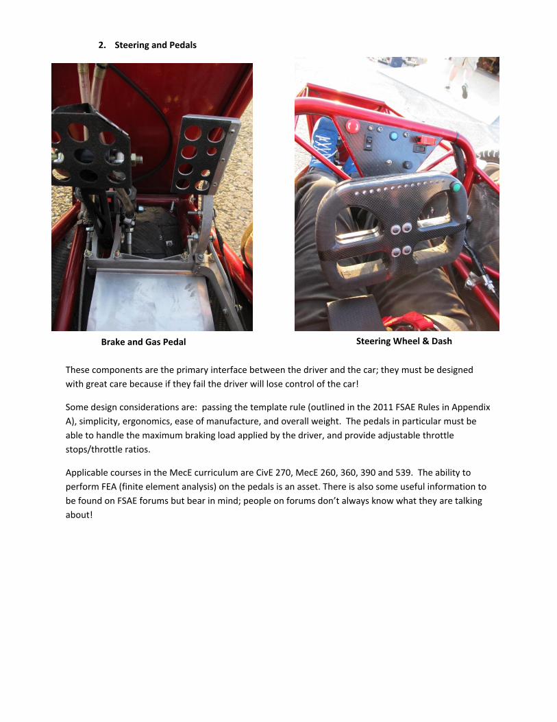
2. Steering and Pedals
These components are the primary interface between the driver and the car; they must be designed
with great care because if they fail the driver will lose control of the car!
Some design considerations are: passing the template rule (outlined in the 2011 FSAE Rules in Appendix
A), simplicity, ergonomics, ease of manufacture, and overall weight. The pedals in particular must be
able to handle the maximum braking load applied by the driver, and provide adjustable throttle
stops/throttle ratios.
Applicable courses in the MecE curriculum are CivE 270, MecE 260, 360, 390 and 539. The ability to
perform FEA (finite element analysis) on the pedals is an asset. There is also some useful information to
be found on FSAE forums but bear in mind; people on forums don’t always know what they are talking
about!
Brake and Gas Pedal Steering Wheel & Dash

3. Hubs & Uprights
The uprights connect the suspension and steering linkages to the wheels, they typically house the brake
disks/callipers. The hubs exist to connect the drive train to the rear wheels, typically composed of a
bearing and CV joint.
These components must: accommodate all of the required suspension points (upper ball joint, lower ball
joint, steering linkage), handle all of the loads that the car will see without failing, keep deflection to a
minimum.
4. Engine Selection
The engine is located in the rear of the car. The primary considerations in choosing an engine are:
power to weight ratio, fuel consumption, ease of integration within the car, and fuel injection (or the
ability to be converted to a fuel injected system)
Some useful information can be found in ‘Fundamentals of Internal Combustion Engines’ by Haywood .
Front Upright and Brake with
Suspension and Steering Linkage Rear Hub & Upright with Suspension Linkage

5. Brakes
The brakes slow the car down, allowing for tighter and faster cornering. There is a lot of heat exchanged
between the kinetic energy of the car and the brake disks/callipers. The callipers, and the fluid pressure
backing them, must be designed to reach the maximum achievable braking force that the tire will allow.
Total weight of this system is critical, as it is located far from the center line of the car and is un-sprung
(having substantial influence on the cars inertia).
6. Electronics & ECU
The cars electrical system is composed of the engine control unit (ECU), shifting controller, tachometer, instrumentation, sensors, and wiring harness (See Pedals & Steering for a photo of the dash) Located behind the seat, the ECU is the brain that makes the engine run. Its main function is to control the ignition timing for the spark plugs and to provide the correct amount of fuel based on engine speed, throttle position, manifold pressure, air temperature, engine temperature, altitude, and more. Adjusting the fuel and ignition timing allows us to achieve the desired power/fuel economy from the engine. This is done via software and also with our eddy current dynamometer. The shifting controller resides next to the ECU and actuates pneumatic cylinders using compressed CO2 to provide shifting and clutch control based upon either steering wheel mounted shift buttons or by electronic signals from the ECU for automatic shifting mode (used in the acceleration event).
Front Brake Assembly Highlighted in Red.

7. Suspension
The suspension connects the chassis to the uprights in the wheels. Suspension components exist to
keep the tires on the ground in all possible cornering/loading situations. The tires selected provide the
biggest physical constraint for the suspension system. The suspension must also fit within the
constraints provided by the hub & upright design as well as the location of the suspension mounts on
the chassis.
Some useful information on this topic may be found in ‘Race Car Vehicle Dynamics’ by Milliken, and
online at www.optimumg.com.
Front Left Suspension Assembly. See Hub & Uprights
for a Better Photo of Suspension Linkages
Rear Suspension
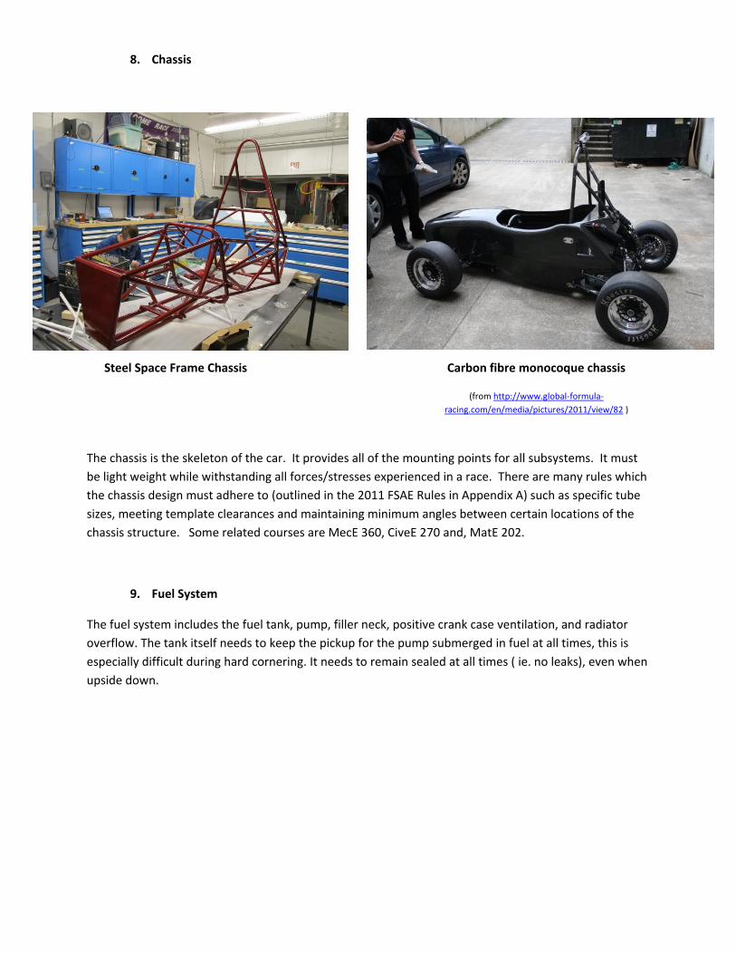
8. Chassis
The chassis is the skeleton of the car. It provides all of the mounting points for all subsystems. It must
be light weight while withstanding all forces/stresses experienced in a race. There are many rules which
the chassis design must adhere to (outlined in the 2011 FSAE Rules in Appendix A) such as specific tube
sizes, meeting template clearances and maintaining minimum angles between certain locations of the
chassis structure. Some related courses are MecE 360, CiveE 270 and, MatE 202.
9. Fuel System
The fuel system includes the fuel tank, pump, filler neck, positive crank case ventilation, and radiator
overflow. The tank itself needs to keep the pickup for the pump submerged in fuel at all times, this is
especially difficult during hard cornering. It needs to remain sealed at all times ( ie. no leaks), even when
upside down.
Steel Space Frame Chassis Carbon fibre monocoque chassis
(from http://www.global-formula-
racing.com/en/media/pictures/2011/view/82 )

10. Drive Train
The drive train’s function is to take power from the engine and deliver it to the rear wheels, and also to
allow a differential speed between the rear wheels for cornering. The drive train is important for many
reasons, namely through applying power to the wheels and to be able to lock up all 4 tires in braking (a
rule outlined in the 2011 FSAE Rules in Appendix A). The limited slip differential is important because it
allows more torque be delivered to the wheel with the most normal load.
Critical design constraints include the maximum torque the engine can produce combined with the
loading of a 10000 rpm clutch drop, or in the opposite direction a driver locking up both rear wheels.
Packaging constraints were that the shocks needed to be placed in a specific position, also the drive
shafts needed to be as straight as possible.
11. Body Panels
The body provides the main aesthetic appeal for the car. It is typically the first thing an observer
notices. Aerodynamics, weight, and aesthetics are the main constraints. It should be noted that cars
using a monocoque chassis don’t require additional body panels because the chassis itself is the body as
well.
Differential, Axle, Rear Sprocket and Rear Brake Highlighted

Frequently Asked Questions 1. How fast does it go? The top speed of a formula SAE car is usually less than 160 km/h. These cars are geared for acceleration. Typical 0-60 mph times are around 4seconds 2. Why don't you turbo it? Turbos are heavy! We are limited by the flow through the air restrictor. A 600cc engine will be drawing the maximum amount of air possible through the restrictor past approximately 8000-9000 rpm. In the end, a turbo doesn’t carry its weight. 3. Why don't you add nitrous? See competition rules. 4. Why aren't we using wings like some other teams? Aerodynamic packages are heavy, complicated to design, build, validate, and tune. At this point in time the team has not had the required man-power to make aerodynamics a beneficial strategy for competition. The team evaluates this decision extensively each year. 5. Who gets to drive? Everyone! We will hold tryout sessions, typically in our two go-karts or a previous year's car. The executive team will select the most appropriate people based on a large number of variables. 6. What are the plans for next year’s car? Ask anyone on the team! We are more than happy to talk about the awesome vehicle we will be making
in the upcoming year.
7. Who goes to competition?
Every year all students are allowed to apply to go to competition. The application is a short letter
describing to the team's executive why you think you should be selected. Typically between 15 and 20
students are taken to any given competition. The executive will select the competition team based on
the amount of commitment and work the individuals have put in.

Appendix A: Related Links 1. U of A FSAE
www.ualbertafsae.com
2. Society of Automotive Engineers
www.sae.org
3. Formula SAE main page
http://students.sae.org/competitions/formulaseries/rules/
4. 2011 FSAE Rules
http://students.sae.org/competitions/formulaseries/rules/2011fsaerules.pdf
5. What is SAE?
http://www.sae.org/about/
6. What other student competitions are there?
http://students.sae.org/competitions/yearinreview/2010.pdf
7. How does SAE define FSAE?
http://students.sae.org/competitions/formulaseries/about.htm
8. 2011 Event Guide
http://students.sae.org/competitions/formulaseries/west/eventguide.pdf
9. Sweet Youtube Video of 2010 Competition etc
http://www.youtube.com/RaceLABtv#p/u/1/_g-PSVyyj-g