university of british columbia cics 515 (part 1) internet computing lecture 1 - overview
DESCRIPTION
University of British Columbia CICS 515 (Part 1) Internet Computing Lecture 1 - Overview. Instructor: Dr. Son T. Vuong Email: [email protected] May 8, 2012 The World Connected. Information and Organization. Instructor: Dr. Son Vuong Email: [email protected] - PowerPoint PPT PresentationTRANSCRIPT

Introduction
University of British Columbia
CICS 515 (Part 1)CICS 515 (Part 1) Internet Computing
Lecture 1 - Overview
Instructor: Dr. Son T. VuongEmail: [email protected]
May 8, 2012
The World Connected
Introduction 1-2
Information and Organization
Instructor: Dr. Son Vuong ► Email: [email protected] ► Office Hours: T, Th: 1:00-2:00pm (CS 329)
TA: ► Jonatan Schroeder [email protected]► Shahed Alam [email protected]
Lectures: T, Th: 11am-1 pm in DMP 110 Lab: Th: 2-4 pm (CS 045/051)

Introduction 1-3
Text and Workload Text: Computer Networking: A Top Down Approach
Featuring the Internet, 6th edition. Jim Kurose, Keith Ross. Addison-Wesley, April 2012.
Course Load:► 2 Projects/Asgmts (20%)► 2 Quizzes (10%)► Midterm (25%)► Final exam (45%)► Bonus for class participation, BlueCT + Peerwise (4%)
Late penalty: 5*2i %, 0< i =< 3 (i = # days late)
Website: www.icics.ubc.ca/~cics515 Vista: http://www.vista.ubc.ca/ (id=pwd=CWL)
Introduction 1-4
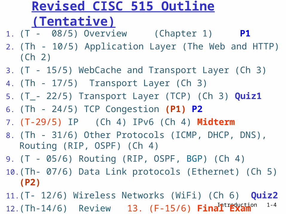
Revised CISC 515 Outline (Tentative)
1. (T - 08/5) Overview (Chapter 1) P1
2. (Th - 10/5) Application Layer (The Web and HTTP) (Ch 2)
3. (T - 15/5) WebCache and Transport Layer (Ch 3)4. (Th - 17/5) Transport Layer (Ch 3) 5. (T - 22/5) Transport Layer (TCP) (Ch 3) Quiz16. (Th - 24/5) TCP Congestion (P1) P27. (T-29/5) IP (Ch 4) IPv6 (Ch 4) Midterm8. (Th - 31/6) Other Protocols (ICMP, DHCP, DNS),
Routing (RIP, OSPF) (Ch 4)9. (T - 05/6) Routing (RIP, OSPF, BGP) (Ch 4)10. (Th- 07/6) Data Link protocols (Ethernet) (Ch 5) (P2)11. (T- 12/6) Wireless Networks (WiFi) (Ch 6) Quiz212. (Th-14/6) Review 13. (F-15/6) Final Exam

Introduction 1-5
Chapter 1: Introduction
Our goal: get context,
overview, “feel” of networking
more depth, detail later in course
approach:► descriptive► use Internet as
example
Overview: what’s the Internet what’s a protocol? network edge network core access net, physical media Internet/ISP structure performance: loss, delay protocol layers, service
models history
Introduction 1-6
Chapter 1: roadmap
1.1 What is the Internet?1.2 Network edge1.3 Network core1.4 Network access and physical media1.5 Internet structure and ISPs1.6 Protocol layers, service models1.7 Delay & loss in packet-switched
networks1.8 History

Introduction 1-7
What’s the Internet: “nuts and bolts” view
millions of connected computing devices: hosts, end-systems► PCs workstations, servers► PDAs phones, toasters
running network apps communication links
► fiber, copper, radio, satellite
► transmission rate = bandwidth
routers: forward packets (chunks of data)
local ISP
companynetwork
regional ISP
router workstation
servermobile

Introduction 1-8
“Cool” internet appliances
World’s smallest web serverhttp://www-ccs.cs.umass.edu/~shri/iPic.html
IP picture framehttp://www.ceiva.com/
Web-enabled toaster+weather forecaster

Introduction 1-9
What’s the Internet: “nuts and bolts” view protocols control sending,
receiving of msgs► e.g., TCP, IP, HTTP, FTP,
PPP
Internet: “network of networks”► loosely hierarchical► public Internet versus
private intranet
Internet standards► RFC: Request for comments► IETF: Internet Engineering
Task Force
local ISP
companynetwork
regional ISP
router workstation
servermobile

Introduction 1-10
What’s the Internet: a service view communication
infrastructure enables distributed applications:► Web, email, games, e-
commerce, database., voting, file (MP3) sharing
communication services provided to apps:► connectionless► connection-oriented
cyberspace [Gibson]:“a consensual hallucination experienced daily by
billions of operators, in every nation, ...."
Introduction 1-11
Uses of Internet
• Business Applications• Home Applications• Mobile Users• Social Issues
Introduction 1-12
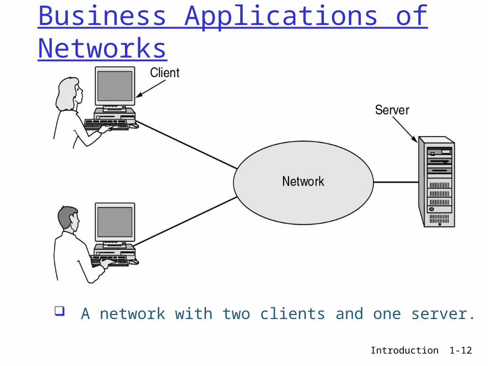
Business Applications of Networks
A network with two clients and one server.
Introduction 1-13
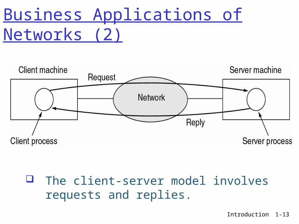
Business Applications of Networks (2)
The client-server model involves requests and replies.
Introduction 1-14
Home Network Applications
Access to remote information Person-to-person
communication Interactive entertainment Electronic commerce
Introduction 1-15
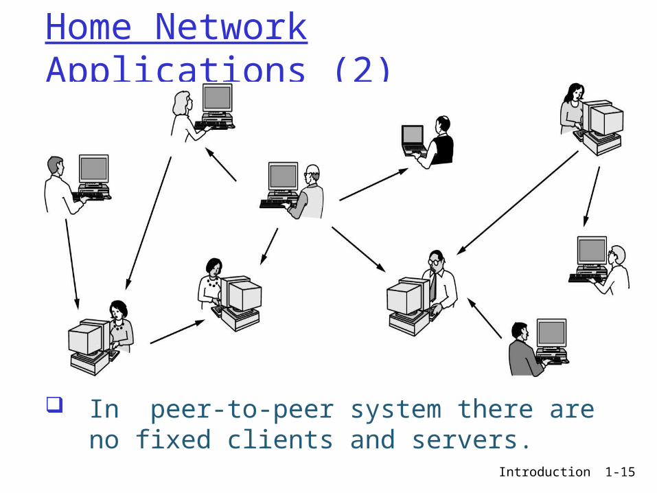
Home Network Applications (2)
In peer-to-peer system there are no fixed clients and servers.
Introduction 1-16
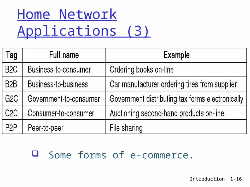
Home Network Applications (3)
Some forms of e-commerce.

Introduction 1-17
Mobile Network Users
Combinations of wireless networks and mobile computing.

Introduction 1-18
Classification of Networks
Classification of interconnected processors by scale.
Introduction 1-19
Example Networks The Internet
Connection-Oriented Networks: X.25, Frame Relay, and ATM
Ethernet
Wireless LANs: 802:11 (WiFi)

Introduction 1-20
Network Perspective Network users: services that their
applications need, e.g., guarantee that each message it sends will be delivered without error within a certain amount of time
Network designers: cost-effective design e.g., that network resources are efficiently utilized and fairly allocated to different users
Network providers: system that is easy to administer and manage e.g., that faults can be easily isolated and it is easy to account for usage
Introduction 1-21
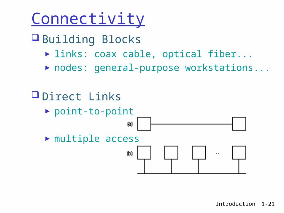
Connectivity Building Blocks
► links: coax cable, optical fiber...► nodes: general-purpose workstations...
Direct Links► point-to-point
► multiple access
Introduction 1-22
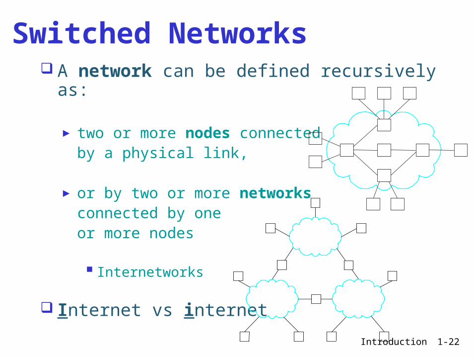
A network can be defined recursively as:
► two or more nodes connected by a physical link,
► or by two or more networks connected by one or more nodes
Internetworks
Internet vs internet
Switched Networks

Introduction 1-23
A closer look at network structure: network edge: applications
and hosts network core:
► routers► network of networks
access networks, physical media: communication links

Introduction 1-24
Chapter 1: roadmap
1.1 What is the Internet?1.2 Network edge1.3 Network core1.4 Network access and physical media1.5 Internet structure and ISPs 1.6 Protocol layers, service models1.7 Delay & loss in packet-switched
networks1.8 History
Introduction 1-25
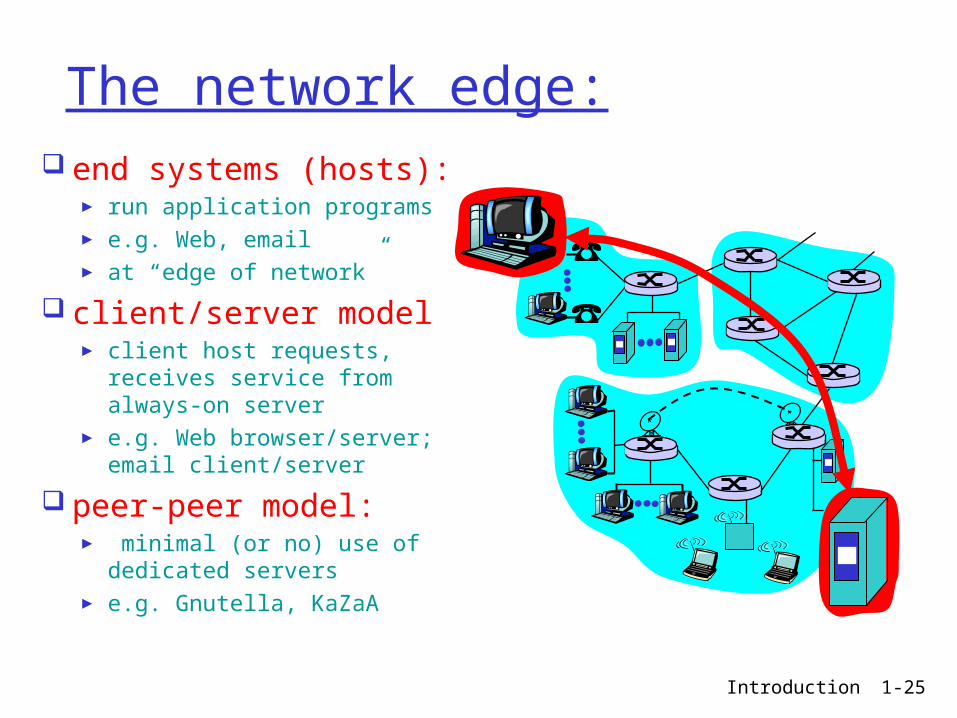
The network edge: end systems (hosts):
► run application programs► e.g. Web, email► at “edge of network”
client/server model► client host requests, receives
service from always-on server► e.g. Web browser/server;
email client/server
peer-peer model:► minimal (or no) use of
dedicated servers► e.g. Gnutella, KaZaA
Introduction 1-26
Network edge: connection-oriented service
Goal: data transfer between end systems
handshaking: setup (prepare for) data transfer ahead of time► Hello, hello back
human protocol► set up “state” in two
communicating hosts
TCP - Transmission Control Protocol ► Internet’s connection-
oriented service
TCP service [RFC 793] reliable, in-order byte-
stream data transfer► loss: acknowledgements
and retransmissions
flow control: ► sender won’t overwhelm
receiver
congestion control: ► senders “slow down
sending rate” when network congested
Introduction 1-27
Network edge: connectionless service
Goal: data transfer between end systems► same as before!
UDP - User Datagram Protocol [RFC 768]: Internet’s connectionless service► unreliable data
transfer► no flow control► no congestion
control
App’s using TCP: HTTP (Web), FTP (file
transfer), Telnet (remote login), SMTP (email)
App’s using UDP: streaming media,
teleconferencing, DNS, Internet telephony
Introduction 1-28
Chapter 1: roadmap
1.1 What is the Internet?1.2 Network edge1.3 Network core1.4 Network access and physical media1.5 Internet structure and ISPs 1.6 Protocol layers, service models1.7 Delay & loss in packet-switched
networks1.8 History
Introduction 1-29
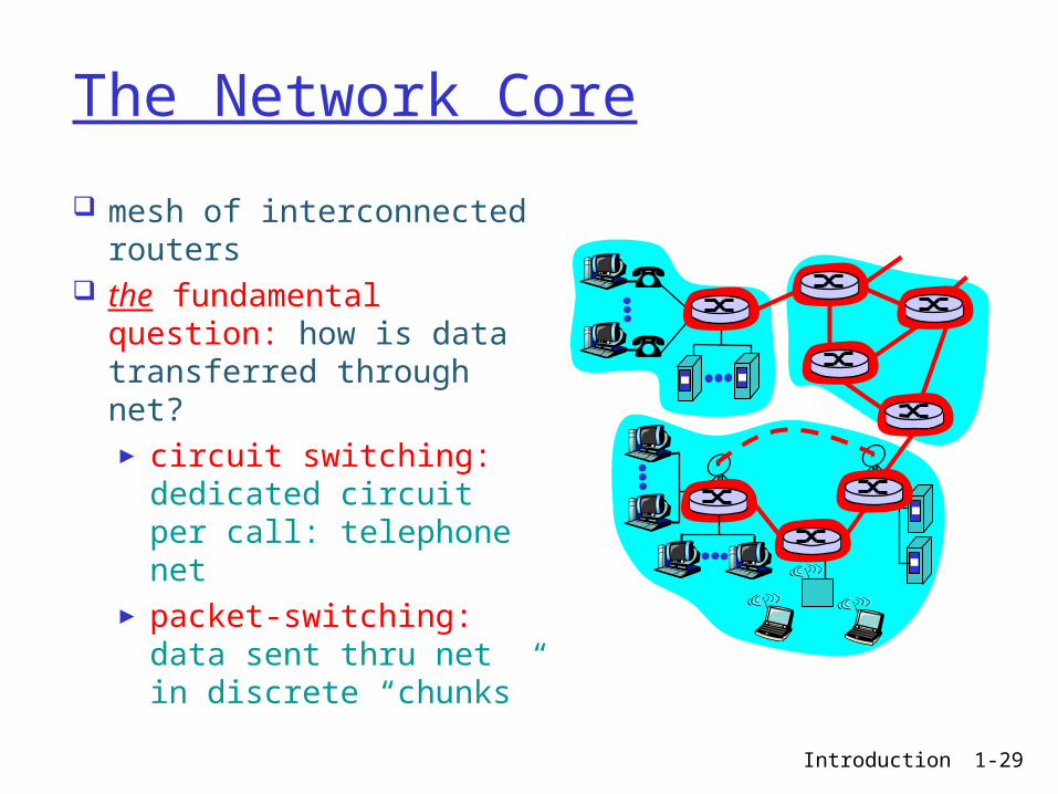
The Network Core
mesh of interconnected routers
the fundamental question: how is data transferred through net?► circuit switching:
dedicated circuit per call: telephone net
► packet-switching: data sent thru net in discrete “chunks”
Introduction 1-30
Circuit switching: dedicated circuit; send/receive a bit stream► original telephone network
Packet switching: store-and-forward; send/receive messages (packets)► Internet
Switching Strategies
Introduction 1-31
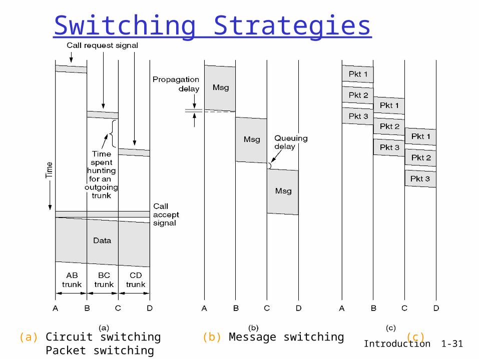
Switching Strategies
(a) Circuit switching (b) Message switching (c) Packet switching

Introduction 1-32
Nodal delay
dproc = processing delay► typically a few microsecs or less
dqueue = queuing delay► depends on congestion
dtrans = transmission delay► = L/R, significant for low-speed links
dprop = propagation delay► a few microsecs to hundreds of msecs
proptransqueueprocnodal ddddd

Introduction 1-33
Packet switching versus circuit switching
Great for bursty data► resource sharing► simpler, no call setup
Excessive congestion: packet delay and loss► protocols needed for reliable data transfer,
congestion control Q: How to provide circuit-like behavior?
► bandwidth guarantees needed for audio/video apps
► still an unsolved problem (chapter 6)
Is packet switching a “slam dunk winner?”
Introduction 1-34
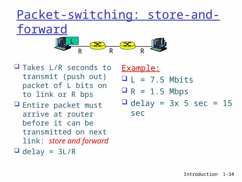
Packet-switching: store-and-forward
Takes L/R seconds to transmit (push out) packet of L bits on to link or R bps
Entire packet must arrive at router before it can be transmitted on next link: store and forward
delay = 3L/R
Example: L = 7.5 Mbits R = 1.5 Mbps delay = 3x 5 sec = 15
sec
R R RL

Introduction 1-35
Packet Switching: Message Segmenting
Now break up the message into 5000 packets
Each packet 1,500 bits
1 msec to transmit packet on one link
pipelining: each link works in parallel
Delay reduced from 15 sec to 5.002 sec

Introduction 1-36
Packet Switching: Message Segmenting
Now assume the message/packets go through 2 additional switches (over the path of 4 switches)
What is the total delay to send the message without breaking into packets (i.e. non-pipelining) ?
What is the total delay to send the message as 5000 packets (i.e. pipelining) ?
R R R
L
R

Introduction 1-37
Q 1.1 Peer Instruction packet switchingNow assume the message/packets go through
2 additional switches (over the path of 4 switches) What is the total delay to send the message as 5000 packets (i.e. pipelining) ?
Answer:
(A) 25 s (B) 15 s (C) 5.002 s (D) 5.004 s (E) None of the above

Introduction 1-38
Q 1.1 Peer Instruction packet switchingNow assume the message/packets go through
2 additional switches (over the path of 4 switches) What is the total delay to send the message as 5000 packets (i.e. pipelining) ?
Answer:
(A) 25 s (B) 15 s (C) 5.002 s (D) 5.004 s (E) None of the above
Introduction 1-39
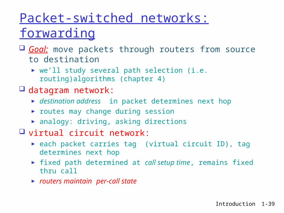
Packet-switched networks: forwarding Goal: move packets through routers from source to
destination► we’ll study several path selection (i.e. routing)algorithms
(chapter 4)
datagram network: ► destination address in packet determines next hop► routes may change during session► analogy: driving, asking directions
virtual circuit network: ► each packet carries tag (virtual circuit ID), tag determines
next hop► fixed path determined at call setup time, remains fixed thru
call► routers maintain per-call state
Introduction 1-40
Addressing and Routing Address: byte-string that identifies a node
► usually unique
Routing: how to forward messages towards the destination node based on its address
Types of addresses► unicast: node-specific► broadcast: all nodes on the network► multicast: some subset of nodes on the
network
Introduction 1-41
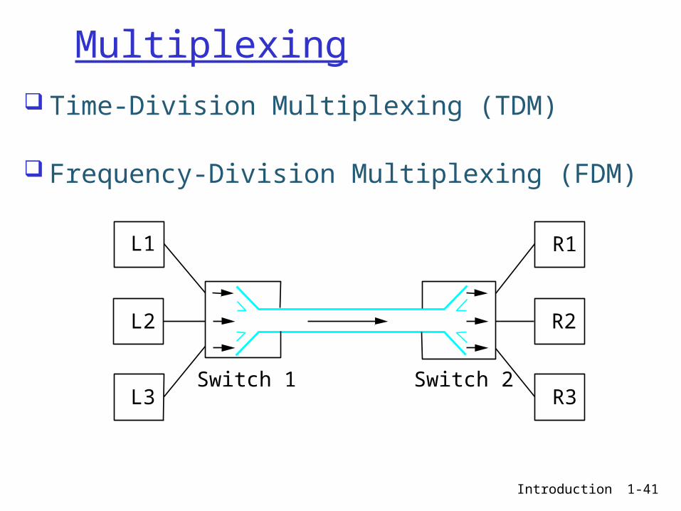
Multiplexing Time-Division Multiplexing (TDM)
Frequency-Division Multiplexing (FDM)
L1
L2
L3
R1
R2
R3Switch 1 Switch 2
Introduction 1-42
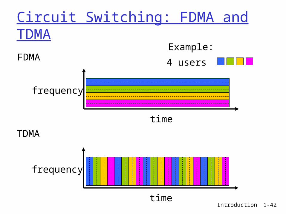
Circuit Switching: FDMA and TDMA
FDMA
frequency
time
TDMA
frequency
time
4 users
Example:
Introduction 1-43
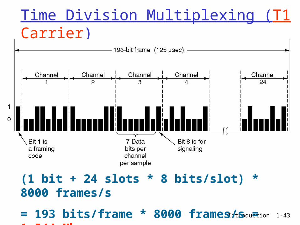
Time Division Multiplexing (T1 Carrier)
The T1 carrier (1.544 Mbps).
(1 bit + 24 slots * 8 bits/slot) * 8000 frames/s
= 193 bits/frame * 8000 frames/s = 1.544 Mbps
Introduction 1-44
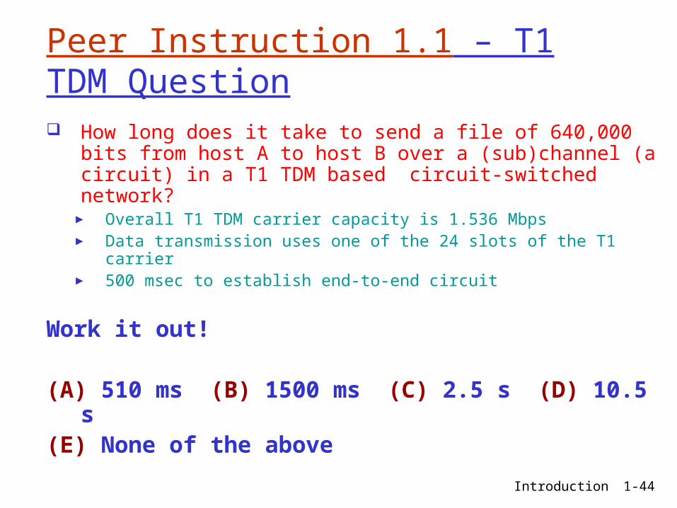
Peer Instruction 1.1 – T1 TDM Question How long does it take to send a file of 640,000 bits
from host A to host B over a (sub)channel (a circuit) in a T1 TDM based circuit-switched network?
► Overall T1 TDM carrier capacity is 1.536 Mbps► Data transmission uses one of the 24 slots of the T1 carrier► 500 msec to establish end-to-end circuit
Work it out!
(A) 510 ms (B) 1500 ms (C) 2.5 s (D) 10.5 s(E) None of the above
Introduction 1-45
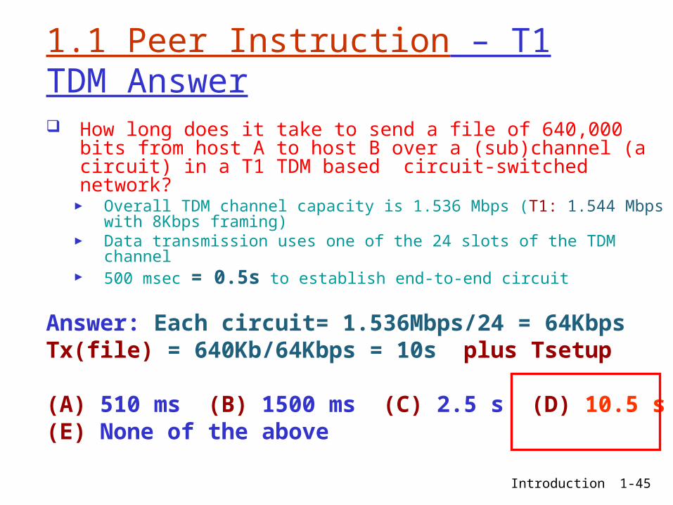
1.1 Peer Instruction – T1 TDM Answer How long does it take to send a file of 640,000 bits
from host A to host B over a (sub)channel (a circuit) in a T1 TDM based circuit-switched network?
► Overall TDM channel capacity is 1.536 Mbps (T1: 1.544 Mbps with 8Kbps framing)
► Data transmission uses one of the 24 slots of the TDM channel► 500 msec = 0.5s to establish end-to-end circuit
Answer: Each circuit= 1.536Mbps/24 = 64Kbps
Tx(file) = 640Kb/64Kbps = 10s plus Tsetup
(A) 510 ms (B) 1500 ms (C) 2.5 s (D) 10.5 s(E) None of the above

Introduction 1-46
Peer Instruction 1.1 – T1 TDM Question How long does it take to send a file of 640,000 bits
from host A to host B over 5 (sub)channels (circuits) in a T1 TDM based circuit-switched network?
► Overall T1 TDM carrier capacity is 1.536 Mbps► Data transmission uses one of the 24 slots of the T1 carrier► 500 msec to establish end-to-end circuit
Work it out!
(A) 510 ms (B) 1500 ms (C) 2.5 s (D) 10.5 s(E) None of the above

Introduction 1-47
1.1 Peer Instruction – T1 TDM Answer How long does it take to send a file of 640,000 bits from
host A to host B over 5 (sub)channel (circuits) in a T1 TDM based circuit-switched network?
► Overall TDM channel capacity is 1.536 Mbps (T1: 1.544 Mbps with 8Kbps framing)
► Data transmission uses one of the 24 slots of the TDM channel► 500 msec = 0.5s to establish end-to-end circuit
Answer: Each circuit= 1.536Mbps/24 = 64Kbps
Tx(file) = 640Kb/(5x64Kbps) = 2s plus Tsetup
(A) 510 ms (B) 1500 ms (C) 2.5 s (D) 10.5 s(E) None of the above
Introduction 1-48
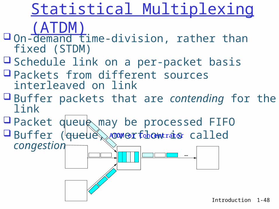
Statistical Multiplexing (ATDM) On-demand time-division, rather than fixed
(STDM) Schedule link on a per-packet basis Packets from different sources interleaved on link Buffer packets that are contending for the link Packet queue may be processed FIFO Buffer (queue) overflow is called congestion
…
ATDM or Concentrator

Introduction 1-49
Chapter 1: roadmap
1.1 What is the Internet?1.2 Network edge1.3 Network core1.4 Network access and physical media1.5 Internet structure and ISPs1.6 Protocol layers, service models1.7 Delay & loss in packet-switched
networks1.8 History

Introduction 1-50
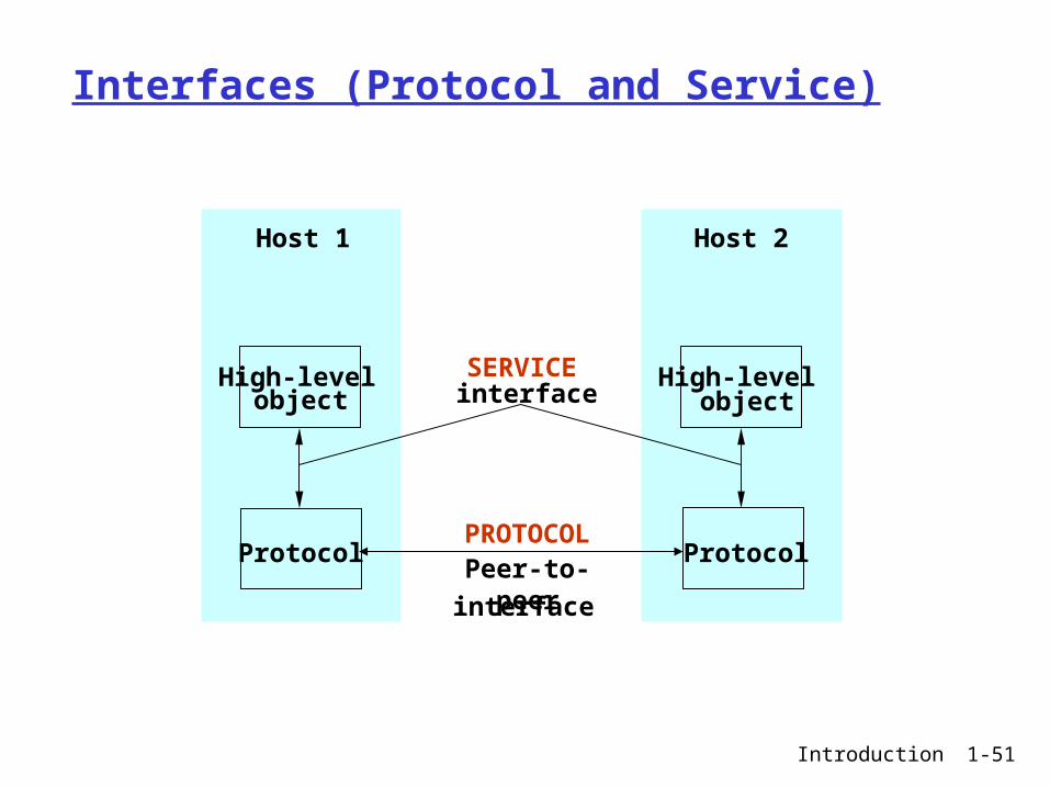
Protocols Building blocks of a network
architecture Each protocol object has two
different interfaces:► service: operations on this protocol► peer-to-peer (protocol): messages
exchanged with peer Term “protocol” is overloaded
► specification of peer-to-peer interface► module that implements this interface
Introduction 1-51
Host 1
Protocol
Host 2
Protocol
High-levelobject
High-levelobject
SERVICEinterface
Peer-to-peer
interface
Interfaces (Protocol and Service)
PROTOCOL

Introduction 1-52
What’s a protocol?human protocols: “what’s the time?” “I have a question” introductions
… specific msgs sent… specific actions
taken when msgs received, or other events
network protocols: machines rather than
humans all communication
activity in Internet governed by protocols
protocols define format, order of msgs sent and
received among network entities, and actions taken on msg transmission, receipt

Introduction 1-53
What’s a protocol?a human protocol and a computer network protocol:
Q: Other human protocols?
Hi
Hi
Got thetime?
2:00
TCP connection req
TCP connectionresponseGet http://www.awl.com/kurose-ross
<file>time

Introduction 1-54
Internet Architecture
Defined by Internet Engineering Task Force (IETF)
Hourglass Design Application vs Application Protocol (FTP,
HTTP)
…
FTP HTTP NV TFTP
TCP UDP
IP
NET1 NET2 NETn
TCP UDP
IP
Network
Application
Introduction 1-55
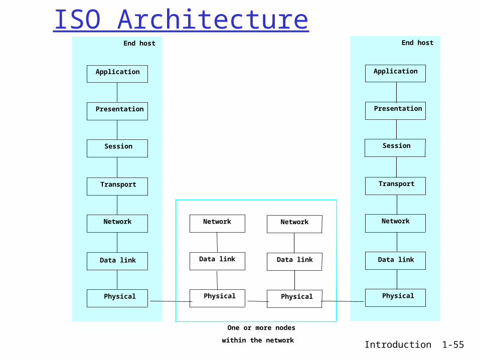
ISO Architecture
Application
Presentation
Session
Transport
End host
One or more nodes
within the network
Network
Data link
Physical
Network
Data link
Physical
Network
Data link
Physical
Application
Presentation
Session
Transport
End host
Network
Data link
Physical
Introduction 1-56
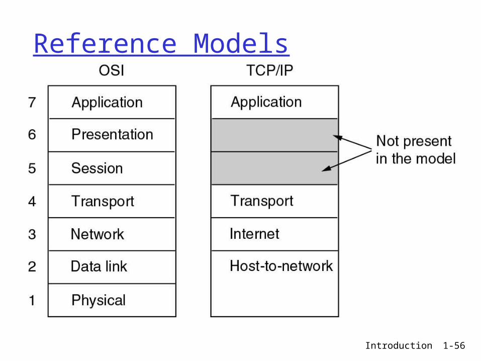
Reference Models
The TCP/IP reference model.

Introduction 1-57
Layering Use abstractions to hide complexity Abstraction naturally lead to layering Alternative abstractions at each layer
Request/replychannel
Message streamchannel
Application programs
Hardware
Host-to-host connectivity
Application programs
Process-to-process
Hardware
Host-to-host connectivity

Introduction 1-58
Layering: logical communication
applicationtransportnetwork
linkphysical
applicationtransportnetwork
linkphysical
applicationtransportnetwork
linkphysical
applicationtransportnetwork
linkphysical
networklink
physical
Each layer: distributed “entities”
implement layer functions at each node
entities perform actions, exchange messages with peers
Introduction 1-59
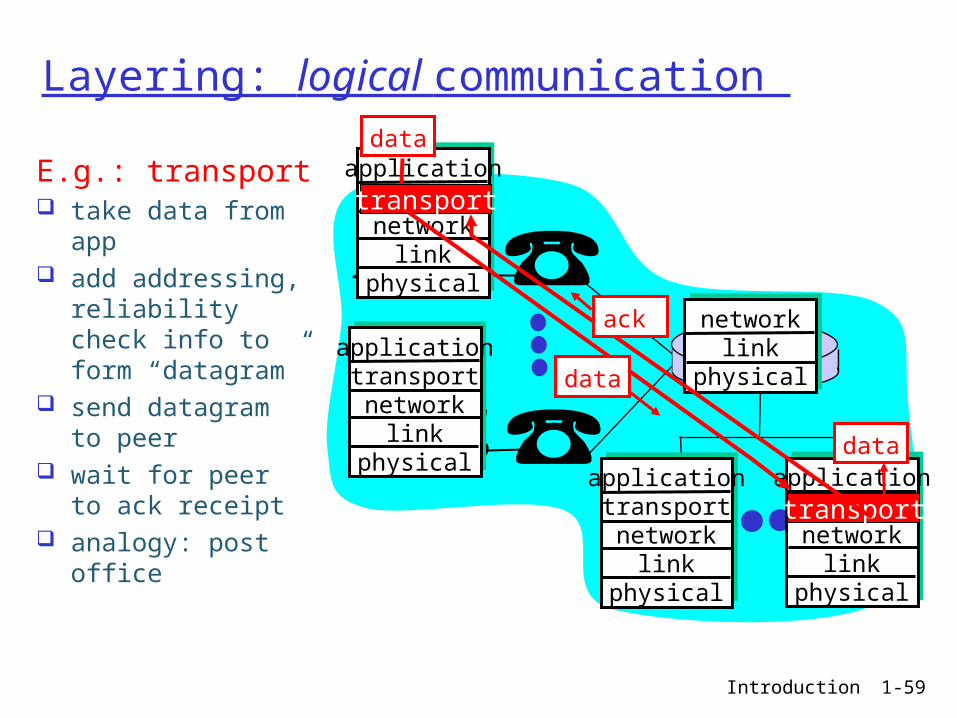
Layering: logical communication
applicationtransportnetwork
linkphysical
applicationtransportnetwork
linkphysical
applicationtransportnetwork
linkphysical
applicationtransportnetwork
linkphysical
networklink
physical
data
data
E.g.: transport take data from
app add addressing,
reliability check info to form “datagram”
send datagram to peer
wait for peer to ack receipt
analogy: post office
data
transport
transport
ack
Introduction 1-60
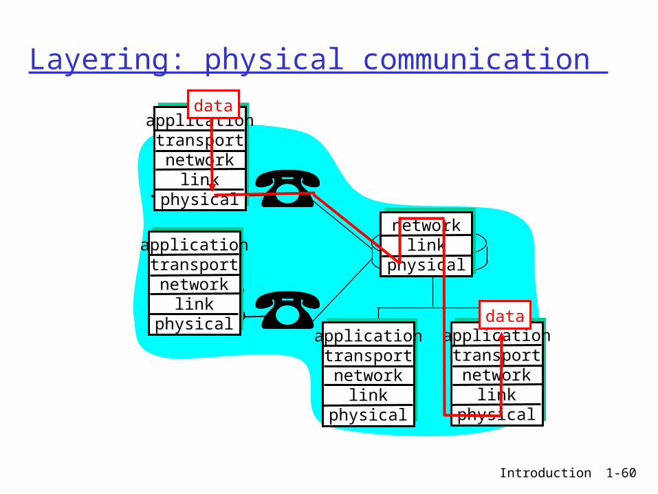
Layering: physical communication
applicationtransportnetwork
linkphysical
applicationtransportnetwork
linkphysical
applicationtransportnetwork
linkphysical
applicationtransportnetwork
linkphysical
networklink
physical
data
data
Introduction 1-61
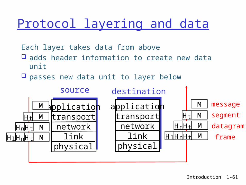
Protocol layering and data
Each layer takes data from above adds header information to create new data unit passes new data unit to layer below
applicationtransportnetwork
linkphysical
applicationtransportnetwork
linkphysical
source destination
M
M
M
M
Ht
HtHn
HtHnHl
M
M
M
M
Ht
HtHn
HtHnHl
message
segment
datagram
frame
Introduction 1-62
Chapter 1: roadmap
1.1 What is the Internet?1.2 Network edge1.3 Network core1.4 Network access and physical media1.5 Internet structure and ISPs 1.6 Protocol layers, service models1.7 Delay & loss in packet-switched
networks1.8 History
Introduction 1-63
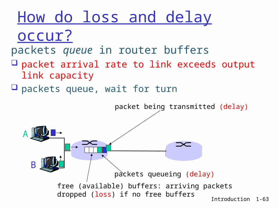
How do loss and delay occur?packets queue in router buffers packet arrival rate to link exceeds output link
capacity packets queue, wait for turn
A
B
packet being transmitted (delay)
packets queueing (delay)
free (available) buffers: arriving packets dropped (loss) if no free buffers

Introduction 1-64
1.2 Peer Instruction - Packet Error Prob Question
Let p be the bit error probability. Assume packet of length L bits. What's the packet error probability in terms of p and L?
(A) (1- p) **L(B) 1- p**L(C) 1- p * L(D) 1- (1-p)**L(E) None of the above
Introduction 1-65
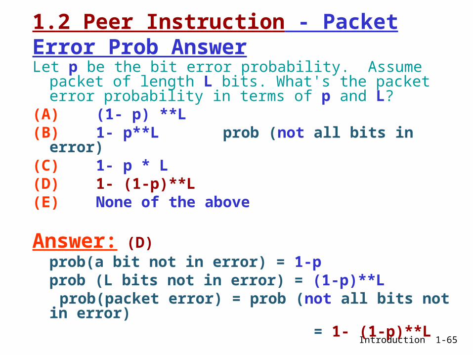
1.2 Peer Instruction - Packet Error Prob AnswerLet p be the bit error probability. Assume packet of
length L bits. What's the packet error probability in terms of p and L?
(A) (1- p) **L(B) 1- p**L prob (not all bits in error) (C) 1- p * L(D) 1- (1-p)**L(E) None of the above
Answer: (D) prob(a bit not in error) = 1-pprob (L bits not in error) = (1-p)**L
prob(packet error) = prob (not all bits not in error)
= 1- (1-p)**L

Introduction 1-66
What Goes Wrong in the Network? Bit-level errors (electrical interference) prob=p Packet-level errors (congestion) = 1-(1-p)f
Link and node failures
Messages are delayed Messages are delivered out-of-order Third parties eavesdrop
The key problem is to fill in the gap between whatapplications expect and what the underlying technology provides.

Introduction 1-67
Four sources of packet delay
1. nodal processing: ► check bit errors► determine output link
A
B
propagation
transmission
nodalprocessing queueing
2. queueing► time waiting at output
link for transmission ► depends on
congestion level of router

Introduction 1-68
Delay in packet-switched networks3. Transmission delay: R=link bandwidth
(bps) L=packet length (bits) time to send bits into
link = L/R
4. Propagation delay: d = length of physical
link s = propagation speed in
medium (~2x10⁸ m/sec) propagation delay = d/s
A
B
propagation
transmission
nodalprocessing queueing
Note: s and R are very different quantities!

Introduction 1-69
Nodal delay
dproc = processing delay► typically a few microsecs or less
dqueue = queuing delay► depends on congestion
dtrans = transmission delay► = L/R, significant for low-speed links
dprop = propagation delay► a few microsecs to hundreds of msecs
proptransqueueprocnodal ddddd
Introduction 1-70
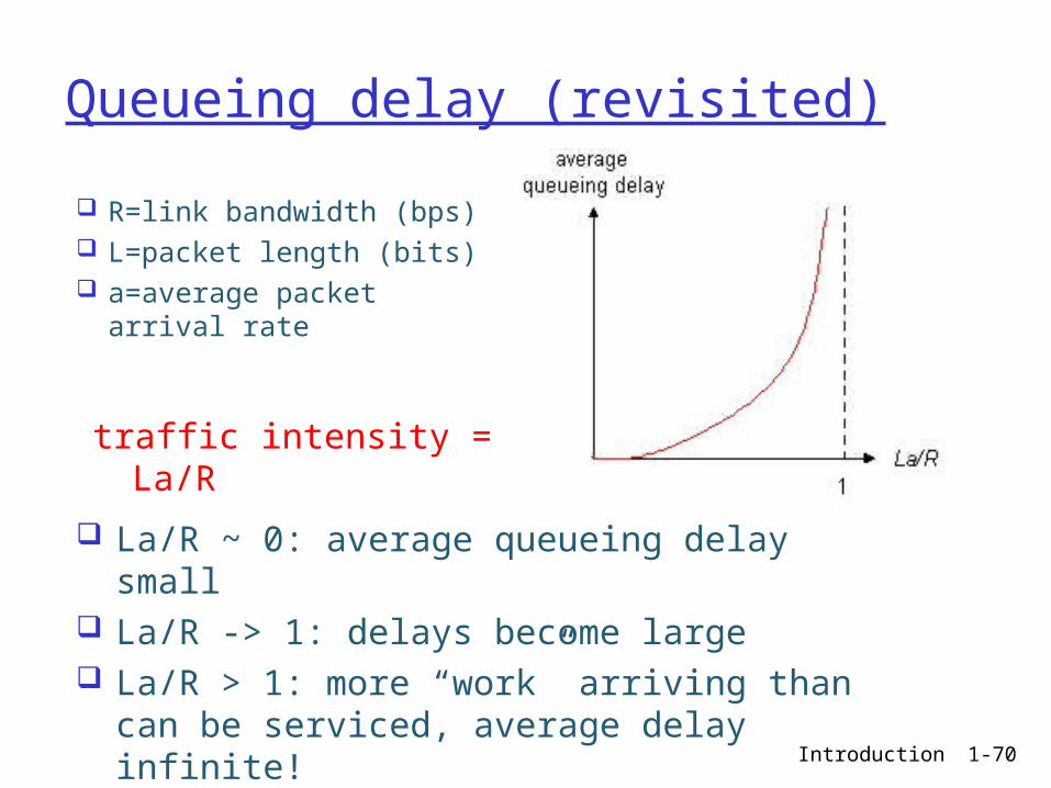
Queueing delay (revisited)
R=link bandwidth (bps) L=packet length (bits) a=average packet
arrival rate
traffic intensity = La/R
La/R ~ 0: average queueing delay small La/R -> 1: delays become large La/R > 1: more “work” arriving than can
be serviced, average delay infinite!
Introduction 1-71
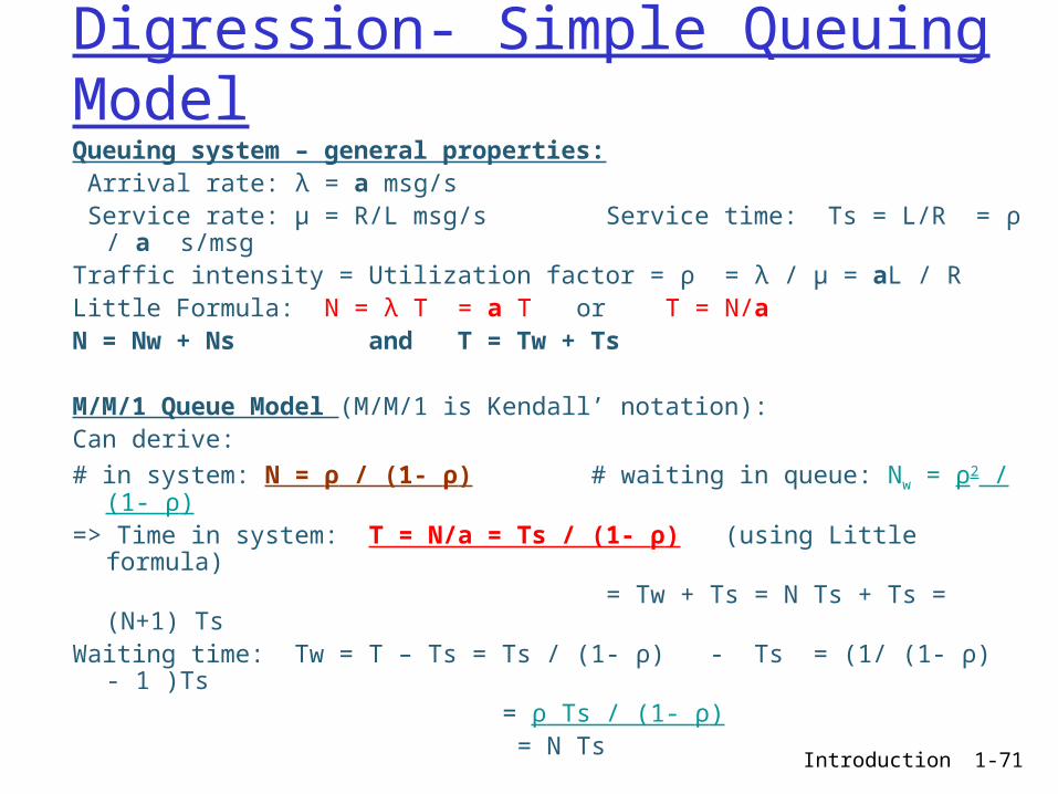
Digression- Simple Queuing ModelQueuing system – general properties: Arrival rate: λ = a msg/s Service rate: μ = R/L msg/s Service time: Ts = L/R = ρ / a
s/msgTraffic intensity = Utilization factor = ρ = λ / μ = aL / RLittle Formula: N = λ T = a T or T = N/aN = Nw + Ns and T = Tw + Ts
M/M/1 Queue Model (M/M/1 is Kendall’ notation):Can derive:# in system: N = ρ / (1- ρ) # waiting in queue: Nw = ρ2 / (1-
ρ) => Time in system: T = N/a = Ts / (1- ρ) (using Little formula) = Tw + Ts = N Ts + Ts = (N+1) TsWaiting time: Tw = T – Ts = Ts / (1- ρ) - Ts = (1/ (1- ρ) - 1 )Ts = ρ Ts / (1- ρ) = N Ts

Introduction 1-72
“Real” Internet delays and routes What do “real” Internet delay & loss look like? Traceroute program: provides delay
measurement from source to router along end-end Internet path towards destination. For all i:► sends three packets that will reach router i on path
towards destination► router i will return packets to sender► sender times interval between transmission and reply.
3 probes
3 probes
3 probes

Introduction 1-73
“Real” Internet delays and routes
1 cs-gw (128.119.240.254) 1 ms 1 ms 2 ms2 border1-rt-fa5-1-0.gw.umass.edu (128.119.3.145) 1 ms 1 ms 2 ms3 cht-vbns.gw.umass.edu (128.119.3.130) 6 ms 5 ms 5 ms4 jn1-at1-0-0-19.wor.vbns.net (204.147.132.129) 16 ms 11 ms 13 ms 5 jn1-so7-0-0-0.wae.vbns.net (204.147.136.136) 21 ms 18 ms 18 ms 6 abilene-vbns.abilene.ucaid.edu (198.32.11.9) 22 ms 18 ms 22 ms7 nycm-wash.abilene.ucaid.edu (198.32.8.46) 22 ms 22 ms 22 ms8 62.40.103.253 (62.40.103.253) 104 ms 109 ms 106 ms9 de2-1.de1.de.geant.net (62.40.96.129) 109 ms 102 ms 104 ms10 de.fr1.fr.geant.net (62.40.96.50) 113 ms 121 ms 114 ms11 renater-gw.fr1.fr.geant.net (62.40.103.54) 112 ms 114 ms 112 ms12 nio-n2.cssi.renater.fr (193.51.206.13) 111 ms 114 ms 116 ms13 nice.cssi.renater.fr (195.220.98.102) 123 ms 125 ms 124 ms14 r3t2-nice.cssi.renater.fr (195.220.98.110) 126 ms 126 ms 124 ms15 eurecom-valbonne.r3t2.ft.net (193.48.50.54) 135 ms 128 ms 133 ms16 194.214.211.25 (194.214.211.25) 126 ms 128 ms 126 ms17 * * *18 * * *19 fantasia.eurecom.fr (193.55.113.142) 132 ms 128 ms 136 ms
traceroute: gaia.cs.umass.edu to www.eurecom.frThree delay measements from gaia.cs.umass.edu to cs-gw.cs.umass.edu
* means no reponse (probe lost, router not replying)
trans-oceaniclink

Introduction 1-74
Packet loss
queue (aka buffer) preceding link in buffer has finite capacity
when packet arrives to full queue, packet is dropped (aka lost)
lost packet may be retransmitted by previous node, by source end system, or not retransmitted at all
Introduction 1-75
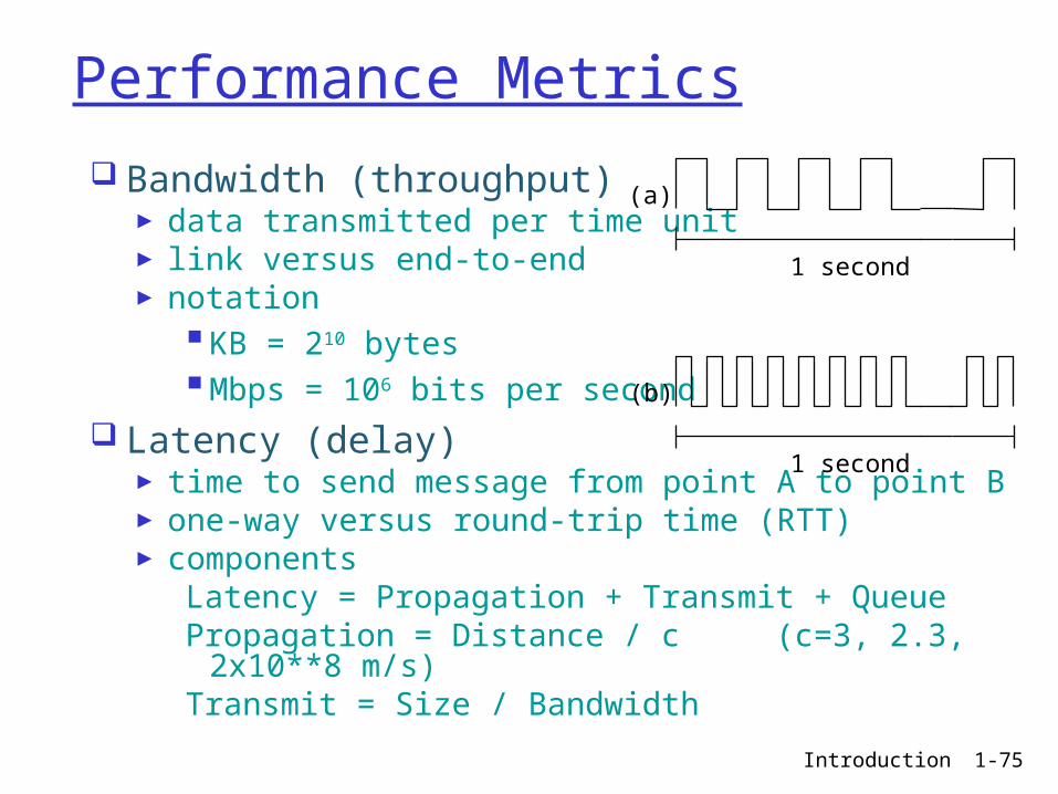
Performance Metrics
Bandwidth (throughput)► data transmitted per time unit► link versus end-to-end► notation
KB = 210 bytesMbps = 106 bits per second
Latency (delay)► time to send message from point A to point B► one-way versus round-trip time (RTT)► components
Latency = Propagation + Transmit + QueuePropagation = Distance / c (c=3, 2.3, 2x10**8 m/s)Transmit = Size / Bandwidth
1 second
(a)
1 second
(b)
Introduction 1-76
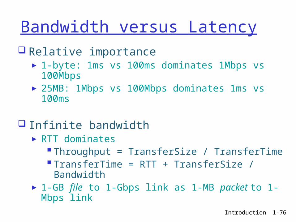
Bandwidth versus Latency Relative importance
► 1-byte: 1ms vs 100ms dominates 1Mbps vs 100Mbps
► 25MB: 1Mbps vs 100Mbps dominates 1ms vs 100ms
Infinite bandwidth► RTT dominates
Throughput = TransferSize / TransferTimeTransferTime = RTT + TransferSize / Bandwidth
► 1-GB file to 1-Gbps link as 1-MB packet to 1-Mbps link
Introduction 1-77
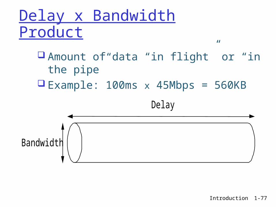
Delay x Bandwidth Product
Amount of data “in flight” or “in the pipe”
Example: 100ms x 45Mbps = 560KB
Bandwidth
Delay

Introduction 1-78
ITU Main sectors
• Radiocommunications• Telecommunications Standardization• Development
Classes of Members• National governments• Sector members• Associate members• Regulatory agencies
Introduction 1-79
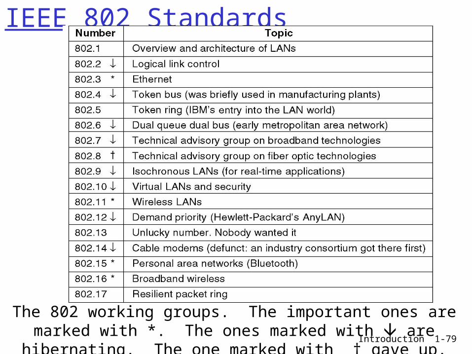
IEEE 802 Standards
The 802 working groups. The important ones are marked with *. The ones marked with are hibernating. The one marked with † gave up.

Introduction 1-80
Bad Timing
The apocalypse of the two elephants.
Introduction 1-81
Chapter 1: roadmap
1.1 What is the Internet?1.2 Network edge1.3 Network core1.4 Network access and physical media1.5 Internet structure and ISPs1.6 Protocol layers, service models1.7 Delay & loss in packet-switched
networks1.8 History
Introduction 1-82
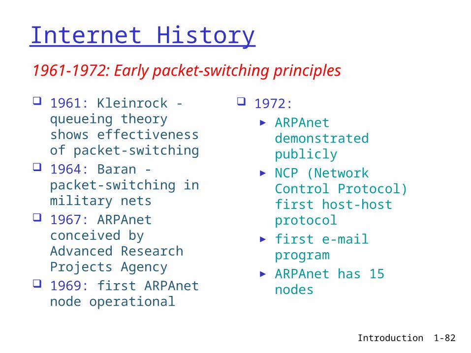
Internet History
1961: Kleinrock - queueing theory shows effectiveness of packet-switching
1964: Baran - packet-switching in military nets
1967: ARPAnet conceived by Advanced Research Projects Agency
1969: first ARPAnet node operational
1972: ► ARPAnet
demonstrated publicly► NCP (Network Control
Protocol) first host-host protocol
► first e-mail program► ARPAnet has 15 nodes
1961-1972: Early packet-switching principles

Introduction 1-83
Internet History
1970: ALOHAnet satellite network in Hawaii
1973: Metcalfe’s PhD thesis proposes Ethernet
1974: Cerf and Kahn - architecture for interconnecting networks
late70’s: proprietary architectures: DECnet, SNA, XNA
late 70’s: switching fixed length packets (ATM precursor)
1979: ARPAnet has 200 nodes
Cerf and Kahn’s internetworking principles:► minimalism, autonomy
- no internal changes required to interconnect networks
► best effort service model
► stateless routers► decentralized control
define today’s Internet architecture
1972-1980: Internetworking, new and proprietary nets

Introduction 1-84
Internet History
1983: deployment of TCP/IP
1982: SMTP e-mail protocol defined
1983: DNS defined for name-to-IP-address translation
1985: FTP protocol defined
1988: TCP congestion control
new national networks: Csnet, BITnet, NSFnet, Minitel
100,000 hosts connected to confederation of networks
1980-1990: new protocols, a proliferation of networks
Introduction 1-85
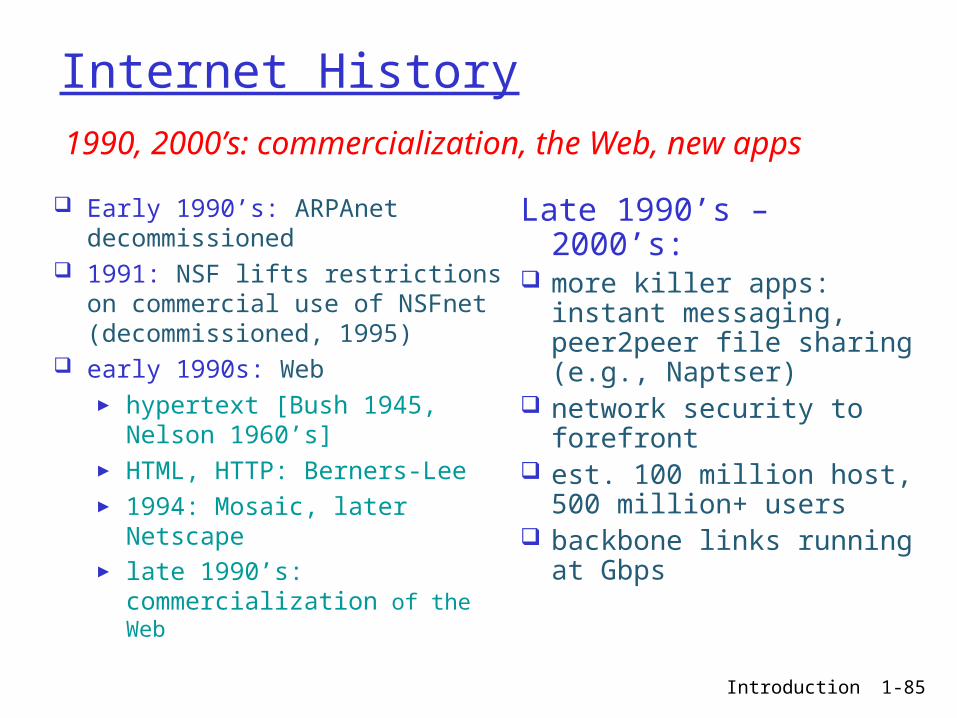
Internet History
Early 1990’s: ARPAnet decommissioned
1991: NSF lifts restrictions on commercial use of NSFnet (decommissioned, 1995)
early 1990s: Web► hypertext [Bush 1945,
Nelson 1960’s]► HTML, HTTP: Berners-Lee► 1994: Mosaic, later
Netscape► late 1990’s:
commercialization of the Web
Late 1990’s – 2000’s:
more killer apps: instant messaging, peer2peer file sharing (e.g., Naptser)
network security to forefront
est. 100 million host, 500 million+ users
backbone links running at Gbps
1990, 2000’s: commercialization, the Web, new apps