university of florida thesis or …zhuang/doc/dissertation.docx · web viewefficient memory...
TRANSCRIPT
EFFICIENT MEMORY HIERARCHY DESIGNS FOR CHIP MULTIPROCESSOR AND NETWORK PROCESSORS
By
ZHUO HUANG
A DISSERTATION PRESENTED TO THE GRADUATE SCHOOLOF THE UNIVERSITY OF FLORIDA IN PARTIAL FULFILLMENT
OF THE REQUIREMENTS FOR THE DEGREE OFDOCTOR OF PHILOSOPHY
UNIVERSITY OF FLORIDA
2010
1

© 2010 Zhuo Huang
2

To my wife and parents
3

ACKNOWLEDGMENTS
Whenever I am looking back for the years that I spent for the PhD studies, I am
always grateful for all the supports, help and love that I received on the way.
First and foremost, I am greatly indebted to my supervisor, Dr. Jih-kwon Peir, for
his continuous encouragement, invaluable and unselfish support in my research over
the past more than six years. His thoughtful coaching with all aspects of my research
was a guarantee of the success of this endeavor. His enthusiasm and preciseness have
left an everlasting impression on me. I will never forget the many nights that he worked
with me for projects during the six years. Without his help, it would not have been
possible for me to complete this research.
My co-advisor, Dr. Shigang Chen, has been always there to listen and give advice.
I am deeply grateful to him for the discussions that helped me sort out the technical
details of my work. I am also thankful to him for encouraging the use of correct grammar
and words in my writings and for carefully reading and commenting on countless
revisions of my writings.
I would like to thank my supervisory committee members Dr. Randy Chow, Dr.
Tao Li, Dr. Renato Figueiredo and Dr. Patrick Oscar Boykin for their insightful and
invaluable advice in my research. Their enthusiasm for research and pursuit for
excellence will be an example to me forever.
I also would like to thank Dr. Prabhat Mishra for his support and indoctrination in
my early years in the PhD program. I learned a lot from the numerous discussions with
him.
4

Special thanks go to Xudong Shi, Gang Liu, Jianmin Chen, Feiqi Su and Zhen
Yang for their invaluable help and guide during the PhD studies. Without them, this
thesis may not be finished for another six years.
I am also thankful to the system staff in the Department of Computer & Information
Science & Engineering (CISE) who maintained all the machines that carry my
simulations.
I am also grateful to John Bowers, Joan Crisman and the other administrative staff
of the CISE department for their various forms of support during my graduate study.
Their kindness warms me every time that I met them.
Many friends have helped me overcome all the difficulties and stay sane through
these years. I greatly appreciate Fei Long, Jianqiang He, Jianlin Li, Yulong Xing, Hua
Xu, Xiao Li, Hechen Liu, Fei Xu, Bin Song and many others whose names cannot all be
listed.
Most importantly, I particularly appreciate my parents and my wife for their
unconditional support and encouragement. I owe my deepest gratitude to my wife for
the six and a half years that I am away from her for this PhD dream. Without her
understanding, love and patience, I would never finish it.
5

TABLE OF CONTENTS
page
ACKNOWLEDGMENTS...................................................................................................4
LIST OF TABLES.............................................................................................................8
LIST OF FIGURES...........................................................................................................9
ABSTRACT....................................................................................................................11
CHAPTER
1 INTRODUCTION.....................................................................................................13
1.1 Memory Hierarchy Designs................................................................................131.2 Space Efficient Chip Multiprocessors (CMP) Coherence Directory Design.......171.3 Space-Efficient Cache Design for Trie-based Network Processor.....................181.4 Hash-Based Routing Table Lookups in Network Processors............................201.5 Performance Evaluation Methodology...............................................................21
2 ALTERNATIVE HOME: BALANCING DISTRIBUTED CHIP MULTIPROCESSOR (CMP) COHERENCE DIRECTORY......................................24
2.1 Motivation..........................................................................................................242.2 Related Works...................................................................................................272.3 Block Distribution among Homes.......................................................................282.4 Distributed CMP Coherence Directory...............................................................29
2.4.1 Randomized Home...................................................................................292.4.2 Alternative Home......................................................................................30
2.5 Directory Lookup and Update............................................................................312.6 Performance Evaluation.....................................................................................33
2.6.1 Simulator and Parameters........................................................................332.6.2 Workload Selection...................................................................................342.6.3 Cached Block Distribution........................................................................352.6.4 Cache Misses and Invalidation Traffic......................................................35
2.7 Summary...........................................................................................................37
3 GREEDY PREFIX CACHE FOR TRIE-BASED IP LOOKUPS................................46
3.1 Motivation..........................................................................................................463.2 Related Work.....................................................................................................483.3 Benefit to Cache the Parent Prefix.....................................................................503.4 Greedy Prefix Cache..........................................................................................52
3.4.1 A Simple Upgrade Example.....................................................................523.4.2 A More Complicated Example..................................................................53
3.5 Handling Prefix Update......................................................................................54
6
3.5.1 Prefix Insertion.........................................................................................543.5.2 Prefix Deletion..........................................................................................55
3.6 Performance Evaluation.....................................................................................553.7 Summary...........................................................................................................57
4 BANDWIDTH-EFFICIENT HASH-BASED NETWORK PROCESSOR....................62
4.1 Problem and Challenge.....................................................................................624.2 Related Works...................................................................................................644.3 The Existing Hashing Approaches.....................................................................66
4.3.1 Single Hash..............................................................................................674.3.2 Non-Deterministic Multi-hashing Schemes...............................................674.3.3 Perfect Hash Function..............................................................................69
4.4 A Novel Deterministic Multi-hashing Scheme (DM-hash)..................................694.4.1 Deterministic Multi-hashing......................................................................694.4.2 Progressive Order....................................................................................724.4.3 Value Assignment for the Index Table......................................................744.4.4 Analysis....................................................................................................75
4.5 Longest Prefix Match with DM-Hash..................................................................764.5.1 Two-level Partition....................................................................................774.5.2 Partial Prefix Expansion...........................................................................78
4.6 Handle Prefix Updates.......................................................................................794.6.1 Insert New Prefixes..................................................................................804.6.2 Delete or Modify Existing Prefixes............................................................814.6.3 Updates with Partial Prefix Expansion......................................................81
4.7 Selective-Multiple Hashing (SM-Hash)..............................................................824.7.1 Setup Algorithm........................................................................................83
4.7.1.1 First-setup.......................................................................................834.7.1.2 Refine-setup....................................................................................84
4.7.2 Handling the Prefix updates.....................................................................844.7.2.1 Basic approach...............................................................................854.7.2.2 Enhanced approach........................................................................85
4.8 Two-Step Hashing (TS-Hash)............................................................................864.9 Experiment Results............................................................................................88
4.9.1 Performance Evaluation Methodology......................................................884.9.2 Bucket Size and Routing Throughput.......................................................894.9.3 Impact of Index Table Size.......................................................................904.9.4 Handle Routing Table Updates................................................................90
4.9.4.1 Handle routing table updates with DM-Hash...................................914.9.4.2 Handle routing table updates with SM-Hash...................................92
4.10 Summary.........................................................................................................92
5 CONCLUSIONS.....................................................................................................105
LIST OF REFERENCES..............................................................................................107
BIOGRAPHICAL SKETCH...........................................................................................114
7
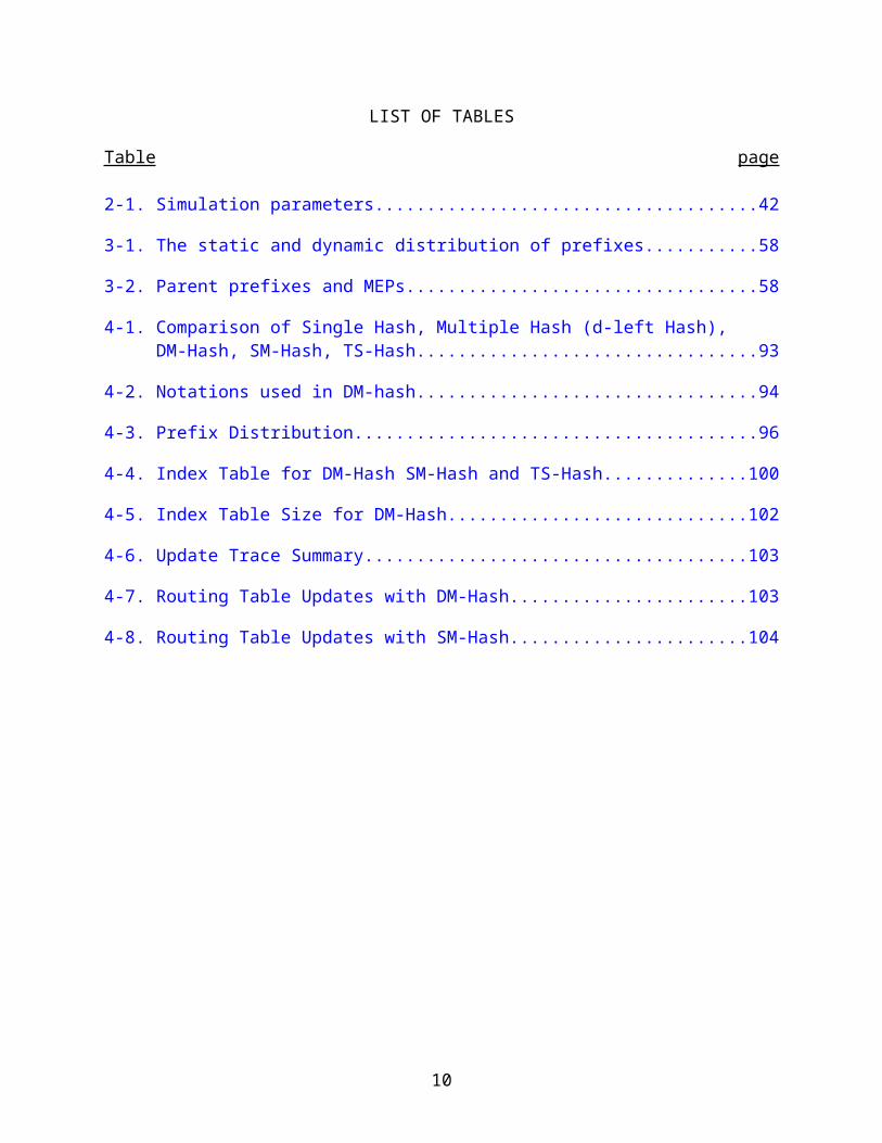
LIST OF TABLES
Table page
2-1. Simulation parameters............................................................................................42
3-1. The static and dynamic distribution of prefixes.......................................................58
3-2. Parent prefixes and MEPs......................................................................................58
4-1. Comparison of Single Hash, Multiple Hash (d-left Hash), DM-Hash, SM-Hash, TS-Hash..............................................................................................................93
4-2. Notations used in DM-hash.....................................................................................94
4-3. Prefix Distribution....................................................................................................96
4-4. Index Table for DM-Hash SM-Hash and TS-Hash................................................100
4-5. Index Table Size for DM-Hash..............................................................................102
4-6. Update Trace Summary........................................................................................103
4-7. Routing Table Updates with DM-Hash..................................................................103
4-8. Routing Table Updates with SM-Hash..................................................................104
8
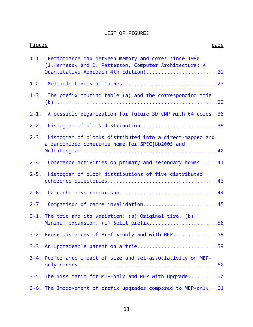
LIST OF FIGURES
Figure page
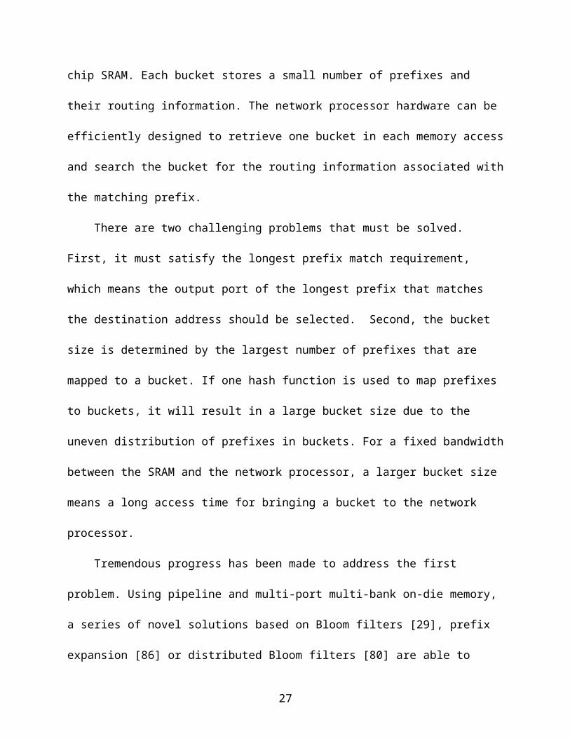
1-1. Performance gap between memory and cores since 1980 (J.Hennessy and D. Patterson, Computer Architecture: A Quantitative Approach 4th Edition)...........22
1-2. Multiple Levels of Caches......................................................................................23
1-3. The prefix routing table (a) and the corresponding trie (b).....................................23
2-1. A possible organization for future 3D CMP with 64 cores......................................38
2-2. Histogram of block distribution...............................................................................39
2-3. Histogram of blocks distributed into a direct-mapped and a randomized coherence home for SPECjbb2005 and MultiProgram........................................40
2-4. Coherence activities on primary and secondary homes.........................................41
2-5. Histogram of block distributions of five distributed coherence directories..............43
2-6. L2 cache miss comparison.....................................................................................44
2-7. Comparison of cache invalidation..........................................................................45
3-1. The trie and its variation: (a) Original tire, (b) Minimum expansion, (c) Split prefix....................................................................................................................58
3-2. Reuse distances of Prefix-only and with MEP.........................................................59
3-3. An upgradeable parent on a trie..............................................................................59
3-4. Performance impact of size and set-associativity on MEP-only caches..................60
3-5. The miss ratio for MEP-only and MEP with upgrade...............................................60
3-6. The Improvement of prefix upgrades compared to MEP-only.................................61
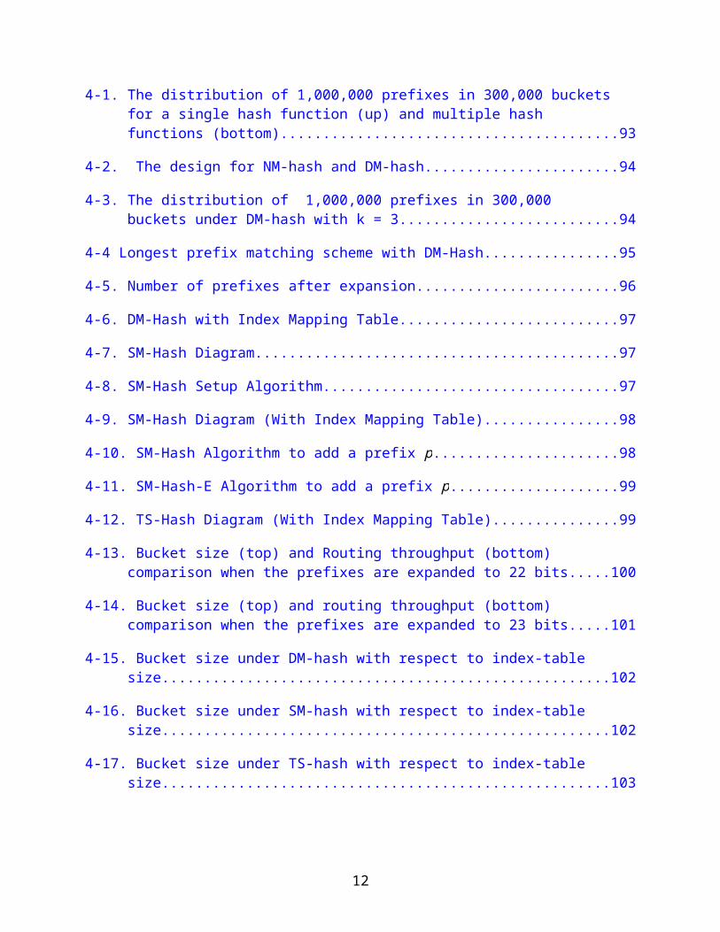
4-1. The distribution of 1,000,000 prefixes in 300,000 buckets for a single hash function (up) and multiple hash functions (bottom)..............................................93
4-2. The design for NM-hash and DM-hash..................................................................94
4-3. The distribution of 1,000,000 prefixes in 300,000 buckets under DM-hash with k = 3.....................................................................................................................94
4-4 Longest prefix matching scheme with DM-Hash......................................................95
9
4-5. Number of prefixes after expansion........................................................................96
4-6. DM-Hash with Index Mapping Table.......................................................................97
4-7. SM-Hash Diagram...................................................................................................97
4-8. SM-Hash Setup Algorithm.......................................................................................97
4-9. SM-Hash Diagram (With Index Mapping Table)......................................................98
4-10. SM-Hash Algorithm to add a prefix p....................................................................98
4-11. SM-Hash-E Algorithm to add a prefix p................................................................99
4-12. TS-Hash Diagram (With Index Mapping Table)....................................................99
4-13. Bucket size (top) and Routing throughput (bottom) comparison when the prefixes are expanded to 22 bits.......................................................................100
4-14. Bucket size (top) and routing throughput (bottom) comparison when the prefixes are expanded to 23 bits.......................................................................101
4-15. Bucket size under DM-hash with respect to index-table size..............................102
4-16. Bucket size under SM-hash with respect to index-table size..............................102
4-17. Bucket size under TS-hash with respect to index-table size...............................103
10
Abstract of Dissertation Presented to the Graduate Schoolof the University of Florida in Partial Fulfillment of theRequirements for the Degree of Doctor of Philosophy
EFFICIENT MEMORY HIERARCHY DESIGNS FOR CHIP MULTIPROCESSOR AND NETWORK PROCESSORS,
By
Zhuo Huang
December 2010
Chair: Jih-Kwon PeirCochair: Shigang ChenMajor: Computer Engineering
There is a growing performance gap between the processor and the main
memory. Memory hierarchy is introduced to bridge the gap for both general propose
processors and the specific processors such as network processors. One major issue
about the multiple-level memory system is that is needed to be efficiently managed so
that the hardware resource is well utilized. In this dissertation, we study three efficient
memory hierarchy designs.
The first work is a space-efficient design for CMP cache coherence directories,
named Alt-Home to alleviate the hot-home conflict. For any cached blocks, the
coherence information can be either stored at one of two possible homes, decided by
two hashing functions. We observe that the Alt-Home approach can reduce of 30-50%
of the L2 miss per instruction compared to the original single-home approaches when
the coherence directory space is limited.
The second work is the greedy prefix cache for trie-based network processor,
which can use the cache more efficiently. A sub-tree (both the parent and leaf prefixes)
can be cached in our greedy prefix cache so that the cache space can be better utilized.
11
The results shows the greedy cache has up to 8% improvement on the prefix cache
miss ratio compared to the best existing approaches.
The third work focuses on the bandwidth efficient network processors. The hash-
based network processor needs to access the hash table to get the routing information.
The hash functions needs to be very balanced so that the memory bandwidth can be
fully utilized. We proposed three new hash functions based on a small on-chip memory
which is available in modern architectures. All of our new approaches can achieve the
routing throughput over 250 millions packets per second. Our approaches can also be
widely applied to other applications involving information storage and retrieval.
12

CHAPTER 1INTRODUCTION
1.1 Memory Hierarchy Designs
Thanks to the development of the submicron technology of silicon VLSI
integration, a single chip current available in the market already has about 3 billion
transistors [64], and as predicted by the famous Moore’s law, tens of billions of
transistors will be available in a single chip in the coming years. Complex wide-issued,
out-of-order single core processors with huge instruction-window and super-pipelined,
super-speculative executions have been designed to utilize the increasing number of
transistors. The advanced processor designs along with the progresses in the silicon
VLSI techniques have improved the processor performance dramatically in last three
decades. In the meantime, the performance/speed of the main memory is improved at a
much slower pace, which creates a huge performance gap between the processor and
the memory, as shown in Figure 1-1.
In order to bridge the gap, a small fast-access storage named Cache has been
used to take the advantage of memory reference locality exhibiting in normal programs.
When a memory location is referenced, it is likely that the location will be re-referenced
in the near future (temporal locality), and when a memory location is referenced, it is
likely the adjacent locations will also be referenced in the near future (spatial locality).
Based on the locality, the recent referenced blocks are placed in cache to reduce the
access time.
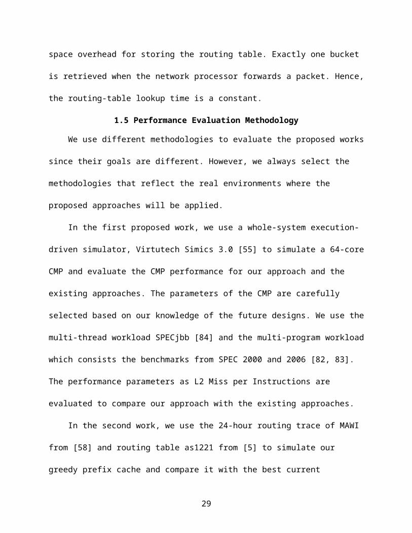
Cache becomes a standard component in current computer systems. Multilevel
caches (as in Figure 1-2) are used to achieve the best trade-off between the access
speed and capacity. A single-core computer system usually has separated first-level
13
instruction and data caches, denoted as L1 Instruction Cache and L1 Data Cache,
which are small with fast access time to match the processor’s speed, and a unified
second-level cache (L2 Cache), which is larger and slower than the L1 caches. The L2
cache can retain the recent instruction and data which cannot fit into the L1 caches to
reduce the L1 miss penalty for accessing the memory. Some proposed architectures
also have an even bigger third level cache (L3 cache) to further reduce the frequency of
memory accesses. The most repeatedly accessed blocks are usually placed in the L1
caches and the L2/L3 caches hold the next-frequently accessed blocks.
Modern processor architectures such as many-core Chip Multiprocessors (CMP)
and advanced Network Processors bring new challenges to the memory hierarchy
design. Although the number of transistors in a chip has been increased according to
Moore’s Law, it is essential to investigate efficient memory hierarchy organizations in
balancing the storage space, access speed, and bandwidth requirement for different
levels of the memory system in modern general-purpose CMPs and advanced network
processors. It is the main objective of this research proposal.
Due to inefficiency in pushing single-core performance using wider and more
speculative pipelining designs, CMP has become the norm in current-generation
microprocessors for achieving high chip-level IPC (Instruction-Per-Cycles.) [37, 66]. The
first CMP is presented in [66]. Currently, there are many CMP processors available on
the market [8, 37, 40, 57, 77], with a small number of cores on a chip [62, 87]. The
number of cores on a single chip has been pushed from tens to hundreds in the recent
projects [7, 89]. Intel announced their experimental “Single-chip Cloud Computer,”
which has 48 cores on a single chip in December 2009 [76].
14

A typical memory hierarchy organization in CMP is shown in Figure 1-2, in which
each core can have its own private L1 (and possibly even a private L2) cache modules.
Since all private caches share the same address space, the blocks with the same
address and stored in different cache modules must be coherent [78]. For example, if
core 0 updates the memory address 0x12345678 in its private cache, any other core
that has the address 0x12345678 in its cache must discard its old copy and get the new
one. The mechanism to maintain the consistency of data stored in all the caches is
named as cache coherence.
Cache coherence can be achieved by using snooping-bus or coherence
directories [78]. The approaches which use a snooping bus put every write request on
the bus. Each cache module listens to the bus and invalidates its copy when a write
operation to the block is observed. However, such approaches can only handle small
number of cores due to the high overhead to implement a snooping bus. Other
approaches use a directory to record the sharers of all blocks in the main memory or all
blocks cached. When a core updates a block, it first searches the directory to figure out
which core contains the block and communicates with only those cores which have the
block in their cache module. Those directories are named as coherence directory.
Although, directory-based approaches are the suitable choice for the future CMPs since
they can handle large number of cores, the coherence directory must be efficiently
designed in terms of the space overhead, speed, and energy.
New challenges of efficient memory hierarchy organizations also come from
application-specific processors such as network processors. Advanced network
processors have been designed to satisfy the high-speed network routing requirement.
15
In such a networking environment, the most challenging and time-consuming task of the
network processor is to perform the IP lookup procedure. A package must be routed
through different network nodes to reach to the destination according to the destination
IP address. The routing information is normally saved in a routing table in each node
which is searched for each incoming packet based on the destination address. There
are three categories of implementation for routing table lookup including the Ternary
Content Addressable Memory (TCAM) [4, 26, 53, 59, 71, 91], the trie-based searches
[27, 30, 35, 39, 43, 47, 54, 73, 74, 81, 86] and the hash-based lookups [16, 28, 29, 34,
48, 79, 80]. With the deploying applications as multimedia content, IPTV, cloud
computing on a high-speed network, the network processors must handle the rapidly
increasing traffic. Hence, the memory hierarchy designs of the network processors
needs to be carefully investigated.
In this proposed research, we investigate three efficient approaches in memory
hierarchy designs. First, we propose a space efficient design for the CMP coherence
directory. A standard coherence directory is costly, especially in space. We propose a
new space-efficient distributed CMP coherence directory named Alternative-Home.
Second, we propose an efficient cache design for trie-based IP-lookup procedures in
network processors. One of the major problems of trie-based approaches is the long
delay for each IP lookup and the multiple accesses to the main memory. A small cache
can be added to benefit from the locality of routing addresses, as in general purposed
processors. A new cache design is developed to improve the cache coverage of the
destination IP addresses. Third, we propose new hash-based IP-lookup approaches in
handling the routing requirement in future high-speed internet. Future network
16
processors need to achieve very high routing throughput to match the traffic speed,
which brings great pressure to the off-chip memory bandwidth of hash-based network
processors. We propose three new hash approaches that can balance the hash buckets
in the routing table and achieve the approximately optimal routing throughput by
reducing the memory accesses for each lookup.
1.2 Space Efficient Chip Multiprocessors (CMP) Coherence Directory Design
In CMP environment, a memory block may exist in more than one private cache
module. When a requested block is missing from the local private cache, the block
needs to be fetched from other caches or memory which has the most-recent copy of
the block. One strategy is to costly search all other cache modules. To avoid
broadcasting and searching all cache modules, directory-based cache-coherence
mechanisms were the choice for building scalable cache-coherent multiprocessors [22].
The recent approaches using a sparse directory records only those cached memory
blocks [33] [65]. One key issue is that the sparse directory must record all the cached
blocks.
The design of a sparse coherence directory for future CMPs faces a new
challenge when the directory is distributed among multiple cores. Based on the block
address, a miss request can be forwarded to the home where the state and the
locations of the block are recorded [56]. Upon a cache miss, the requested block can be
fetched from the memory module located at the home. Although the directory size is
partitioned equally among homes, the cached block addresses are often distributed
unevenly. The uneven distribution must be efficiently handled with constant directory
size.
17
The uneven distribution among different homes results in one of the following two
scenarios. First, if the space for some home is insufficient, it cannot record all the
cached blocks which should be recorded in the home. The block which is not recorded
must be invalidated from all the cores for cache coherence. It reduces the effective
cache size and results in the significant performance reduction. Second, if sufficient
spaces are given to each home in the way that all of them can record all the cache
blocks, only the home with the largest number of records fully utilizes its space and
significant space is wasted in the other homes.
In the first work of this dissertation, we introduce a new distributed CMP
coherence directory that uses an alternative home to balance the block distribution
among homes. Each home location is determined by a different hashing function of the
block address. The state and locations of a block can be recorded in one of two
possible homes. We borrow a classical load balancing technique to place each missed
block in the home with more empty space [6, 60]. Performance evaluations based on
multi-threaded and multi-programmed workloads demonstrate significant reductions of
block invalidations due to insufficient directory space using the alternative home
approach.
1.3 Space-Efficient Cache Design for Trie-based Network Processor
The network routing information is usually stored in the routing table, which
contains the outgoing network interface and the output port for any possible destination
IPs. Since a destination subnet with a unique network ID usually consists of a large
number of hosts, the packages to these hosts are often routed through the same set of
intermediate hops. Instead of recording the <IP-address, Out-port> pair, the routing
table size can be greatly reduced by only recording the output port for each routing
18

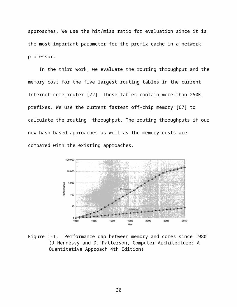
prefix, denoted by <Prefix, Out-port>. The prefix is a bit string followed by a *, where the
* is a wildcard that matches any bit string from the remaining destination IP address.
For example a prefix 01* can match any address whose first two bits are 01. A prefix is
8 to 32 bits long for IPv4 and 16 to 64 bits long for IPv6. There can be multiple prefixes
which match the same destination address in a routing table. The router must select
the longest one to match the address. This requirement introduces the longest prefix
matching (LPM) problem.
Trie-based approaches use one-bit tree (trie) to organize the prefixes. Figure 1.3
(a) shows an example of a routing table with two prefixes. When looking up an address,
the search procedure starts from the root node and goes to left child or the right child
based on the corresponding bit. The search procedure ends when the needed child
doesn’t exist.
The most serious disadvantage of trie-based approaches is the long latency. It
needs to access the memory (where the trie stores) multiple times to get the final prefix.
In addition, these multiple accesses are dependant so that it cannot be overlapped.
Based on the locality study, a small, fast cache can be added to reduce the latency [19,
21, 31]. However, caching the prefixes is complicated due to the LPM requirement.
In the second work of this dissertation, we proposed a new cache approach called
greedy prefix cache in handling trie-based routing lookups. Greedy prefix cache is more
space efficient since it can cover more prefixes than the existing approaches with the
same cache size. Our simulation results based on the 24-hour trace from MAWI [58]
and the as1221 routing table [5] shows that about 6-8% reduction of cache miss rate
can be achieved.
19
1.4 Hash-Based Routing Table Lookups in Network Processors
Hashed-based network processors use hash tables to store the prefixes and their
routing information. Compared with the TCAM or Trie-based approaches, the hash-
based routing table approach is power-efficient and is able to handle large routing
tables.
Our study investigates the hash-based approach that maps the prefixes in a
routing table into an array of buckets in the off-chip SRAM. Each bucket stores a small
number of prefixes and their routing information. The network processor hardware can
be efficiently designed to retrieve one bucket in each memory access and search the
bucket for the routing information associated with the matching prefix.
There are two challenging problems that must be solved. First, it must satisfy the
longest prefix match requirement, which means the output port of the longest prefix that
matches the destination address should be selected. Second, the bucket size is
determined by the largest number of prefixes that are mapped to a bucket. If one hash
function is used to map prefixes to buckets, it will result in a large bucket size due to the
uneven distribution of prefixes in buckets. For a fixed bandwidth between the SRAM
and the network processor, a larger bucket size means a long access time for bringing a
bucket to the network processor.
Tremendous progress has been made to address the first problem. Using pipeline
and multi-port multi-bank on-die memory, a series of novel solutions based on Bloom
filters [29], prefix expansion [86] or distributed Bloom filters [80] are able to determine
the prefix length for hash-based routing table lookup in a few or even one clock cycle.
This leaves the fetch of routing information (in buckets) from the off-chip SRAM to the
network processor as the throughput bottleneck of the lookup function. Hence, the third
20
work of this proposal will focuses on the latter problem. Given an address prefix, we
want to quickly identify the bucket or buckets that may contain its routing information
and fetch them to the processor. In order to maximize the lookup throughput, the key is
to reduce the number of buckets and the size of each bucket that needs to be brought
to the processor for each packet.
In the third work of this dissertation, we develop three novel hash-based
approaches to maximize the lookup throughput. The new approaches use the default
small on-chip memory as an index table to encode information that helps the network
processor to determine exactly which bucket holds a given prefix. The size of the index
table is made small, making it easy to fit in on-die cache memory. The values stored in
the table can be chosen to balance the prefix distribution among buckets and
consequently minimize the bucket size, which in turn reduces the space overhead for
storing the routing table. Exactly one bucket is retrieved when the network processor
forwards a packet. Hence, the routing-table lookup time is a constant.
1.5 Performance Evaluation Methodology
We use different methodologies to evaluate the proposed works since their goals
are different. However, we always select the methodologies that reflect the real
environments where the proposed approaches will be applied.
In the first proposed work, we use a whole-system execution-driven simulator,
Virtutech Simics 3.0 [55] to simulate a 64-core CMP and evaluate the CMP performance
for our approach and the existing approaches. The parameters of the CMP are carefully
selected based on our knowledge of the future designs. We use the multi-thread
workload SPECjbb [84] and the multi-program workload which consists the benchmarks
21
from SPEC 2000 and 2006 [82, 83]. The performance parameters as L2 Miss per
Instructions are evaluated to compare our approach with the existing approaches.
In the second work, we use the 24-hour routing trace of MAWI from [58] and
routing table as1221 from [5] to simulate our greedy prefix cache and compare it with
the best current approaches. We use the hit/miss ratio for evaluation since it is the most
important parameter for the prefix cache in a network processor.
In the third work, we evaluate the routing throughput and the memory cost for the
five largest routing tables in the current Internet core router [72]. Those tables contain
more than 250K prefixes. We use the current fastest off-chip memory [67] to calculate
the routing throughput. The routing throughputs if our new hash-based approaches as
well as the memory costs are compared with the existing approaches.
Figure 1-1. Performance gap between memory and cores since 1980 (J.Hennessy and D. Patterson, Computer Architecture: A Quantitative Approach 4th Edition)
22
Figure 1-2. Multiple Levels of Caches
(a) (b)
Figure 1-3. The prefix routing table (a) and the corresponding trie (b)
23
<Prefix Next Hop><01* Port A> (parent prefix)<0100*Port B> (child prefix)

CHAPTER 2ALTERNATIVE HOME: BALANCING DISTRIBUTED CHIP MULTIPROCESSOR (CMP)
COHERENCE DIRECTORY
In order to build a space-efficient coherence directory in a distributed directory-
based CMP, we investigate a new CMP coherence directory design to balance the
uneven home distribution among the distributed directories. Besides the original home
decided by the direct indexing, an alternative home can be also used to keep the
coherence information. The directory information can be allocated to either home for
balancing the distribution. In this chapter, we first show the motivation of this work in 2,1
followed by the existing work in 2.2. We show the block distribution in 2.3 and
demonstrate the unbalancing between different homes when the home is selected by
the conventional simple hashing of the block address. Alternative home is proposed
which is selected on a second hashing function to achieve better balancing, by placing
the block in the home with small number of blocks. In 2.4, we examine the directory
lookup schemes for our new alternative home approaches. Experiment results based on
multi-threaded and multi-programmed workloads are shown in 2.5 to demonstrate the
significant reduction of L2 misses per instruction with the alternative home approach.
2.1 Motivation
Chip Multiprocessor (CMP) concept has been well accepted in both academia and
industry since it can utilize the billions of transistors on a single chip to achieve high
chip-level IPC (Instruction-Per-Cycles) [37, 66].
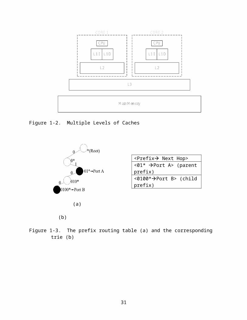
Meanwhile, researchers proposed a new norm named 3-dimentional (3D) chips
[10, 49] based on the advances of the wafer stacking technology and electrothermal
design methods. Figure 1.2 shows a possible 64-core 3D chip design in the future. By
stacking multiple levels of wafers together, 3D chip provides an order of magnitude
24

increase in both processor cores and on-chip storage space. We anticipate a class of
CMP organization that consists of many cache modules, each local to a core. Multiple
pairs of core and cache module are interconnected through a 2D-mesh network to form
a tile-like interconnected organization [7]. In addition, the 3D memory+logic stacking
technology will probably be mature in handling off-chip memory accesses [9]. Block-
based interleaved memory modules are located directly above the associated core-
cache pairs and can be accessed through the fast vertical interconnect.
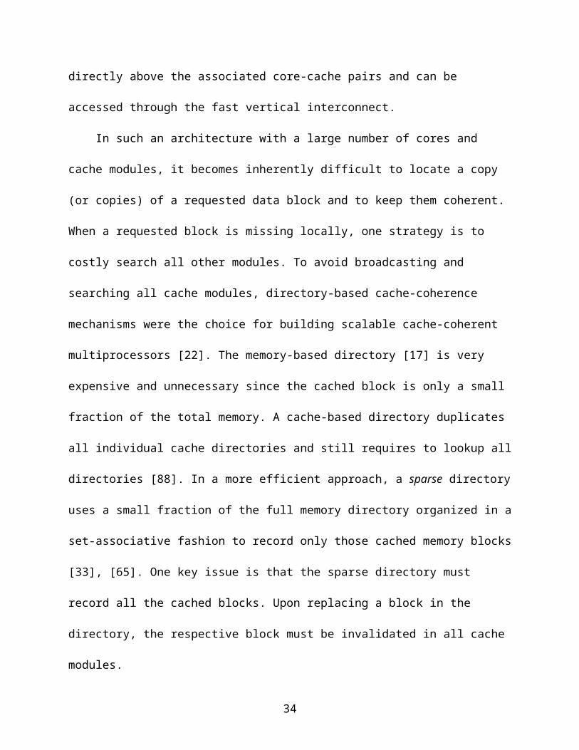
In such an architecture with a large number of cores and cache modules, it
becomes inherently difficult to locate a copy (or copies) of a requested data block and to
keep them coherent. When a requested block is missing locally, one strategy is to costly
search all other modules. To avoid broadcasting and searching all cache modules,
directory-based cache-coherence mechanisms were the choice for building scalable
cache-coherent multiprocessors [22]. The memory-based directory [17] is very
expensive and unnecessary since the cached block is only a small fraction of the total
memory. A cache-based directory duplicates all individual cache directories and still
requires to lookup all directories [88]. In a more efficient approach, a sparse directory
uses a small fraction of the full memory directory organized in a set-associative fashion
to record only those cached memory blocks [33], [65]. One key issue is that the sparse
directory must record all the cached blocks. Upon replacing a block in the directory, the
respective block must be invalidated in all cache modules.
Although the broadcasting and searching all cache modules can be avoided by
using the directory, the directory needs extra space to store the necessary information.
For example, in a 64-core CMP, it needs at least 64 bits (as a bit vector) to record
25
whether a block is shared among all the cache modules. Since a cache block is usually
64Byte, we can see the space overhead is about 1/8 of the on-chip cache size if we
make the directory to have the same number of entries as the cache blocks. When the
future CMP has hundreds of cores, the space overhead of directory is even larger.
Hence, the directory size (or the number of entries) needs to be reduced to maintain the
coherence directory space efficient. However, the inefficient directory space will cause
performance loss. If there is no more space in the directory to record the state of a
cache block, the block itself or some other block needs to be invalidated so that the
directory can keep the precise information of all the cached blocks. So how to choose
the suitable coherence directory size is challenging.
The design of a sparse coherence directory for future CMPs faces another
challenge when the directory is distributed among multiple cores. Based on the block
address, a miss request can be forwarded to the home where the state and the
locations of the block are recorded [56]. Upon a cache miss, the requested block can be
fetched from the memory module located above the home. However, due to an uneven
distribution of cached block addresses, the required size of the distributed directory at a
home can vary significantly. When the directory size is partitioned equally among
homes, insufficient directory space in some hot-homes where more than average
cached blocks are recorded causes inadvertent block invalidations.
In this section, we introduce a new distributed CMP coherence directory that uses
an alternative home to alleviate the hot-home conflict. The state and locations of a block
can be recorded in one of two possible homes. Each home location is determined by a
different hashing function of the block address. Fundamentally, the alternative home
26
extends a direct-mapping for a unique home to a two-way mapping for locating an
empty directory slot from two possible homes. We also borrow a classical load
balancing technique to place each missed block in the home with more empty space
load [6, 60].
2.2 Related Works
There has been a long history in designing directory-based cache coherence
mechanisms for shared-memory multiprocessor systems [2, 45, 50]. The sparse
directory approach uses a small fraction of the full memory directory to record cached
memory blocks [33, 65]. Studies have shown that the number of entries in such a
directory must be significantly larger than the total number of cache blocks to avoid
inadvertent cache invalidations. In a recent virtual hierarchy design [56], a 2-level
directory is maintained in a Virtual Machine (VM) environment. The level-1 coherence
directory is combined with the L2 tag array in the dynamically mapped home tile located
within each VM domain. No inclusion is maintained between the home L2 directory and
all the cached blocks. Any unresolved accesses will be sent to the level-2 directory. If
the block is predicted to be on-chip, the request is broadcast to all cores.
There have been many works in alleviating conflict misses [1, 2, 9, 12, 85] One
interesting work is the skewed cache [85] which randomized the cache index by
exclusing-oring the index bits with adjacent higher-order bits. The V-way cache [69]
alleviates the conflict by doubling the cache directory size. It may not solve the hot-set
problem since the expanded directory entries in the hot sets can still be occupied. The
adaptive cache insertion scheme [68] dynamically selects blocks to be inserted into the
LRU position, instead of the MRU position for handling cache capacity problem for a
27

sequence of requests with long reuse distances that cannot fit into the limited cache by
the LRU replacement policy.
In future many-core CMPs with 3-D DRAM-logic stacking technology, it is efficient
to interconnect many cores and cache modules in a tiled structure using a 2-D mesh
network while placing the DRAM modules right above the processor cores for fast
accesses [7]. The coherence directory can be distributed among the cores in line with
the memory block allocation. To our knowledge, this is the first work to consider an
alternative home in implementing a distributed sparse coherence directory. This
alternative home solution can be complimentary to the virtual hierarchy design [56] for
alleviating home conflicts at their first-level coherence directory.
2.3 Block Distribution among Homes
In Figure 2-2, the histograms of blocks distributed among homes are plotted for
SPECJBB-2005 [84] and a multi-program workload with mixed SPEC programs
(referred as MultiProgram). These workloads ran on a Simics 3.0 [55] whole-system
simulation environment. We simulated a CMP with 64 cores, and each core has a
private 128KB, 8-way, L2 cache with 64-byte blocks. A total of 8MB L2 is simulated. We
simulated distributed coherence directories among 64 cores with infinite size. Each
cached block has a unique home determined by the last 6 bits of the block address.
Multiple counters are maintained to count the number of cached blocks that each home
must record when a block is loaded or removed from a core.
Figure 2.2 demonstrates severe disparity in the number of blocks distributed
among homes. It also shows a significant difference in data sharing between
SPECJBB2005 and MultiProgram. For SPECJBB-2005, the number of blocks that must
be recorded in each home ranges from 450 to 900 with an average about 660. For
28
MultiProgram, the range increases to between 1450 and 1950 with an average about
1740. Due to data sharing, the number of distinct blocks is much smaller in
SPECJBB2005 than that in MultiProgram. In both workloads, the wide range in the
number of recorded blocks in each home makes the directory design difficult. Severe
block invalidations will be encountered unless a bigger directory is provided that can
record extra 20-40% of the average number of cached blocks.
2.4 Distributed CMP Coherence Directory
In this section, we describe the fundamental CMP coherence directory design
when an alternative home is available for each block. Although an alternative home
generates additional traffic for directory lookups and updates, it does not impose any
delay in the critical cache coherence activities and memory accesses. The amount of
invalidation traffic will be measured in Section 2.5.
2.4.1 Randomized Home
Consider a CMP with n cores, each hosting a part of the coherence directory. A
straightforward home selection scheme, call direct-mapped, is to take the lower-order
log2n index bits of a block address to determine the home where the state and locations
of the block is recorded. With the 3D memory-logic stacking technology, all memory
blocks can be allocated based on the log2n index bits directly above the home directory,
which can be fetched through the vertical interconnect when they are not present in the
caches[10] . Although suffering the potential hot-home conflicts (see Section 2.3), the
direct-mapped selection scheme is simple and has been adopted widely.
To remedy the hot-home conflicts, an alternative approach is to randomize the
home selection. One straightforward scheme is to select the home by exclusive-oring
the lower-order log2n bits with the adjacent higher-order log2n bits of the block address
29
[75]. The memory block allocation can be adjusted accordingly. To understand the
cached block distribution with randomized homes, we simulate again with SPECjbb2005
and MultiProgram to show the histograms of block distributions among the homes
(Figure 2.3). In this figure, we also include the histogram from the direct-mapped
scheme (Single-DM) for comparison purpose. The results show that randomized home
selection (Single-ran) indeed improves the evenness of the block distribution. However,
a home still must record a wide range of the number blocks. Hence, to avoid inadvertent
invalidations the directory size must be large enough to cover the maximum number of
blocks.
2.4.2 Alternative Home
To further alleviate the uneven block distribution among the homes, our approach
is to record the state and locations of a cached block in one of two possible homes,
determined by two different hash functions applied to the block address. With two
homes, there are two key mechanisms for balancing the block distribution. The first is
which of the two homes a block is actually placed into. For this, we can borrow ideas
from an abstract load-balancing model of sending N balls to N bins. If, for each ball, we
choose a random bin and place the ball into the chosen bin, the average number of
balls per bin is clearly 1. However, the bin with the maximum number of balls has about
logN balls, which is quite a bit larger than the average. On the other hand, if we choose
two bins randomly for each ball and place the ball in the bin with fewer balls, then, in the
end, the most loaded bin has about log(logN) balls, an exponential reduction in the
maximum load. The result is that the load of the bins is much better balanced in the two-
choice case than the single-choice case. This drastic improvement of load balance
using such a simple trick has been rigorously proven [6, 60].
30
The second key is the randomness of the hash functions used to select the two
homes. In this paper, we consider a simple direct-mapped approach to determine the
first home, called the primary home. For selecting the secondary home, we consider two
approaches. The first approach is to simply organize the two homes as two-way set
associative, where the secondary home can be decided by flipping the most significant
bit of the log2n index bits. Although not randomized, this simple two-way set-associative
selection balances the blocks between a fixed pair of homes. The second approach is to
select the secondary home using the straightforward randomization function as
described in Section 2.4.1.
The selection of homes is complicated by the fact that each distributed directory is
normally implemented as set-associative. Set selection within each home also plays a
role in the number of cache invalidations. For set selection, we also consider the same
two hash functions, i.e. the direct-mapped and the straightforward randomization similar
to that in the home selection.
2.5 Directory Lookup and Update
When a local cache miss occurs, the requested block address is forwarded to both
homes. The state and locations of the block can be found in one and only one home
directory if the block is located in one or more on-die caches. Proper cache coherence
activities and data block movement can be initiated and the associated directory
information is updated afterwards. When the block does not exist in either home
directory, the requested block must be missing from all caches. In this case, the primary
home initiates a memory request to the next lower-level of the memory hierarchy. An
empty slot in either home directory must be picked to record the newly cached block.
When no empty slot is available in either directory, one of the existing blocks must be
31

removed from its current home directory to make a room for the new block. When a
block is replaced from the caches, a notification must be sent to both homes to update
the directory. Figure 2.3 illustrates the flow of the coherence operations in both the
primary and the secondary homes. It is important to emphasize that the critical
coherence and memory access activities do not incur any extra delay with an alternative
home. The detailed directory lookup and update algorithm is described as follows.
Primary Home:
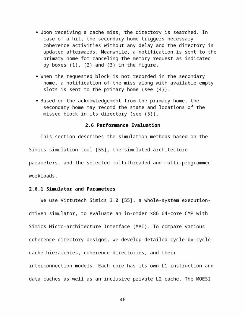
When a core’s cache miss comes, the directory is searched. In case of a hit, the primary home triggers necessary coherence activities without any delay and the directory is updated afterwards as indicated by boxes (1) and (2) in the figure.
When the requested block is not recorded in the primary home, a request is initiated to the memory immediately for fetching the missed block (as shown in (3)). Such a request is canceled if a notification from the secondary home indicates the block is actually located in caches (see (4)). In this case, no further action is needed for the primary home.
There are different cases if the notification from the secondary home also indicates a cache miss of the requested block. First, if the primary home has more empty slots in the directory, the state and locations of the missed block is recorded upon the return of the missed block (see (5)). Second, if the primary home has less empty slots than the secondary home for the missed block, the primary home returns an acknowledgement for the secondary home to record the missed block (see (7)).
When none of the above two cases is encountered, there is no empty slot in either home. The primary home will remove the LRU block from the set where the missed block is mapped into. Invalidations are sent to caches where the LRU block is located (see (6)).
Secondary Home:
Upon receiving a cache miss, the directory is searched. In case of a hit, the secondary home triggers necessary coherence activities without any delay and the directory is updated afterwards. Meanwhile, a notification is sent to the primary home for canceling the memory request as indicated by boxes (1), (2) and (3) in the figure.
When the requested block is not recorded in the secondary home, a notification of the miss along with available empty slots is sent to the primary home (see (4)).
32

Based on the acknowledgement from the primary home, the secondary home may record the state and locations of the missed block in its directory (see (5)).
2.6 Performance Evaluation
This section describes the simulation methods based on the Simics simulation tool
[55], the simulated architecture parameters, and the selected multithreaded and multi-
programmed workloads.
2.6.1 Simulator and Parameters
We use Virtutech Simics 3.0 [55], a whole-system execution-driven simulator, to
evaluate an in-order x86 64-core CMP with Simics Micro-architecture Interface (MAI).
To compare various coherence directory designs, we develop detailed cycle-by-cycle
cache hierarchies, coherence directories, and their interconnection models. Each core
has its own L1 instruction and data caches as well as an inclusive private L2 cache. The
MOESI coherence protocol is applied to maintain L2 cache coherence through a
distributed sparse coherence directory, which is evenly distributed among 64 cores.
When a requested block is not in the local L2 module, the request is routed to the
corresponding coherence directory home (or homes) based on the block address and
the directory organization. If the block is not in any of the CMP caches, the block will be
fetched from the associated DRAM module.
Each core has one request queue for sending requests to the network and one
incoming request queue for receiving requests from the network. Each core is attached
to a router, which routes traffic to the four directly-connected routers. Our simulator
keeps track of the states of all the requests, queues and routers. The delay for each
request is carefully calculated by enqueuing, dequeuing, router stages, routing conflicts
and directory/remote L2 cache/main memory access, etc. We assume the point-to-point
33
wiring delay between two routers is 1 cycle and the routing takes only 1 cycle at each
router [46]. For simplicity, we simulate a simple route-ahead scheme such that each
message is routed from the source to destination atomically. We do take the conflicts
along the path into consideration that may lengthen the routing delay. Given a light
traffic load, <15% for SPECJBB2005 and <5% for MultiProgram for the alternative home
scheme, this simple routing strategy is reasonable. Table 2-1 summarizes a few
parameters in our simulation.
2.6.2 Workload Selection
SPECJBB2005 (java server) is a java-based 3-tier online transaction processing
system [84]. We simulate 64 warehouses. We skip first 5000 transactions, and then
simulate 250 transactions after warming up the structures with 250 transactions. We
also simulate a mixed SPEC2000[82] (Mcf, Parser, Twolf, and Vpr, Ammp, Art, Mesa,
and Swim) and SPEC2006 [83](Astar, Bzip2, Gcc, Gobmk, Libquantum, Mcf, Sjeng, and
Xalan) applications, each with 4 copies. To alleviate perturbations among simulations of
multiple directory configurations, we run multiple simulations for each directory
configuration of each workload and inserted small random noises (perturbations) in the
latency of main memory access. However, we still experience noticeable differences
due to different instruction executions among simulated directory configurations. To
make a fair comparison, we decide to collect an execution trace based on a direct-
mapped single home with infinite directory and use the trace to compare various
distributed directory designs.
Five CMP coherence directory organizations including direct-mapped single home
(single-DM), randomized single home (single-ran), set-associative two homes (2home-
2way), randomized two homes with fully-associative directory (2home-ran-full) and
34

randomized two homes with random set selection (2home-ran-set) are compared. The
set selection within each home for the first three organizations is direct-mapped. For
2home-ran-set, the set selection in the primary home is direct-mapped while it is
randomized in the secondary home; both use the adjacent higher-order bits next to the
bits that are used for home selection. 2home-ran-full is included in the evaluation to
serve as a performance upper bond. The block distribution, the hit/miss improvement,
and the invalidation traffic will be presented and compared.
2.6.3 Cached Block Distribution
The histograms of cached blocks distributed among 64 cores for the five simulated
coherence directory organizations are plotted in Fig. 2.5. Clearly, 2home-ran-set shows
a more even block distribution than that of single-DM, single-ran and 2home-2way for
both workloads. With randomized set selection, the evenness in block distribution of
2home-ran-set closely matches to that in 2home-ran-full, which requires an unrealistic
fully-associative directory. 2home-2way does not help much for distributing the block
more evenly. This is due to the fact that 2home-2way has the two home restricted to a
fixed pair. Effectively, it is equivalent to a single home using a directory with doubled
set-associativity. Single-ran can balance the blocks better than that of 2home-2way.
2.6.4 Cache Misses and Invalidation Traffic
The evenness of the cached block distribution is reflected in cache invalidations
and L2 cache misses. Fig. 2.6 shows the normalized L2 cache misses per instruction for
single-DM, single-ran, and 2home-ran-set under four directory sizes. The normalization
is with respect to single-DM with the smallest directory. From the results for
SPECJBB2005, we can make two important observations. First, as expected, 2home-
ran-set has the fewest L2 misses per instruction followed by single-ran, and then by
35

single-DM. Compared with single-DM and single-ran, the improvement in L2 misses per
instructions in 2home-ran-set is very significant with about 30-50% and 9-12%,
respectively. Second, the directory size plays an important role in the L2 misses per
instruction. L2 misses per instruction increase substantially for small directory sizes.
However, 2home-ran-set can compensate the reduction of directory size. For example,
2home-ran-set with a 576-entry directory reduces the L2 misses per instruction
compared with the single-DM with 768-entry directory. The improvement of
MultiProgram is not as significant, but still follows the same trend; 2home-ran-set
outperforms single-DM and single-ran by about 2-5%.
In Fig. 2.7, we show the total cache invalidations under single-DM, single-ran, and
2home-ran-set with four coherence directory sizes. The invalidations are further
categorized into the normal coherence invalidations due to updates and the
invalidations due to insufficient directory space. We can observe that for
SPECJBB2005, a majority of the cache invalidations are due to block updates, while for
MultiProgram, the invalidations are mainly due to the directory size constraint. The three
directory schemes have substantial differences in the amount of invalidations caused by
insufficient directory size. With randomized two homes and randomized sets in each
home, 2home-ran-set produces a much smaller amount of cache invalidations than that
of single-DM, and single-ran. This smaller amount of invalidations is the primary reason
for lowered L2 misses per instruction as described in Figure 2-6.
It is important to point out that due to data sharing, SPECJBB2005 requires the
directory size much smaller than the total L2 cache sizes. In this study, we consider the
costly full presence bits in each directory entry to record all the sharers. The needed
36

directory size increases significantly if the sparse pointers are used to record wide
sharers using multiple directory entries[50]. Notice also that for MultiProgram, sizeable
invalidations are still experience for single-DM and single-ran even when the directory
size is close to the L2 cache size. This is due to the set conflicts within each home.
2.7 Summary
In this research, we describe an efficient cache coherence mechanism for future
CMPs with many cores and many cache modules. We argue in favor of a directory-
based approach. However, the design of a low-cost coherence directory with small size
and small set-associativity for future CMPs must handle the hot-home conflicts when
the directory is distributed to all cores. We introduce and evaluate an alternative home
approach that allows each cached block to be recorded in one of two possible homes.
By examining two possible homes randomly and selecting the one with more empty
space, the cached blocks can be more evenly distributed among all homes. Compared
with the traditional single-home approach, the proposed approach shows significant
reduction in block invalidations and in cache misses per instruction.
37
Figure 2-1. A possible organization for future 3D CMP with 64 cores
38
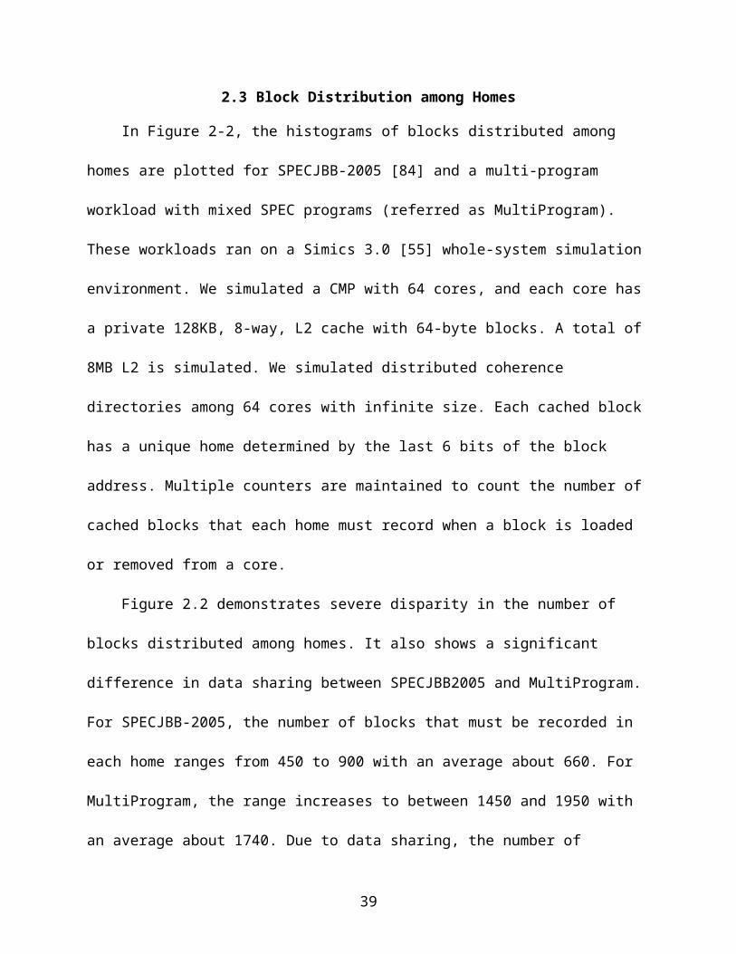
Figure 2-2. Histogram of block distribution
39

Figure 2-3. Histogram of blocks distributed into a direct-mapped and a randomized coherence home for SPECjbb2005 and MultiProgram
40
Figure 2-4. Coherence activities on primary and secondary homes
41

Table 2-1. Simulation parametersCMP and Caches
64 cores, 4GHz, in-order coresL1-I/D: 8KB/8KB, 4-way, 64B line, write-back, 1-cyclePrivate L2: 128KB, 8-way, 64B line, write-back, inclusive, 15 cycles, MOESI protocolRemote L2: 35 cycles + network latency DRAM access: 225 Cycles + network latencyRequest/response queues to/from directory: 8entries
Coherence DirectoryMain directory: Distributed 64 Banks, MOESIRequest/response queues to/from each core: 8 entriesPrimary directory access latency: 10 cyclesRemote block access latency: 10 additional cycles
Interconnection NetworkNetwork topology: 2-D 8*8 MeshPoint-to-point wire delay: 1 cycleRouting delay: 1 cycle per router Message Packing/Unpacking delay: 1 cycle Message Routing: Route-ahead to destination
42

Figure 2-5. Histogram of block distributions of five distributed coherence directories
43

Figure 2-6. L2 cache miss comparison
44

Figure 2-7. Comparison of cache invalidation
45
CHAPTER 3GREEDY PREFIX CACHE FOR TRIE-BASED IP LOOKUPS
In this chapter, we describe a new prefix cache design named greedy prefix cache
for trie-based network processors. It improves the prefix cache performance by allowing
caching the largest sub-tree of each prefix including the parent prefixes. In the following
of this chapter, we first show the motivation and the related works in section 3.1 and
3.2. We discuss the different approaches of using cache in the trie-based network
processors in 3.3. Examples of how greedy prefix cache works are given in 3.4 while
3.5 shows the algorithms of our approaches. Our experiment results show that the
prefix cache using the proposed upgrade scheme can reduce the miss ratio by about 6-
8% compared to the best existing prefix caching mechanism.
3.1 Motivation
The IP lookup needs to be resolved efficiently by either hardware or software.
There are three main categories of LPM approaches including the Ternary Content
Addressable Memory (TCAM)[4, 26, 53, 59, 71, 91], the trie-based searches [27, 30, 35,
39, 43, 47, 54, 73, 74, 81, 86] and the hash-based lookups [16, 28, 29, 34, 48, 79, 80].
Trie-based approaches use a tree-like structure to store the prefixes with the matched
output ports. They consume low power, less storage spaces, and can handle prefix
updates easily. In addition, the LPM requirement can be satisfied naturally through
searching the trie. The main problem of trie-based approaches is the long lookup
latency involving multiple memory operations.
Based on the locality study, previous works [19, 21, 31] added a small, fast cache
to reduce the latency. The recent routing results are saved in the cache, so when such
46
routes are revisited in the near future, the destination ports can be retrieved directly
from the cache.
The most straightforward way to utilize the locality is to cache the IP addresses
that are recently visited. A pair of <IP, next hop> can be stored in the cache for future
reference. For example, if an 8-bit IP address 0100000 is visited and the trie-based
algorithm figured out the next hop is Port A based on Figure 3.1, <01000000,Port B>
can be directly stored into the cache. Next time if the address 01000000 is visited again,
the next hop information can be directly achieved from the cache. Although IP cache is
easy to implement, the space efficiency is low. For example, Considering 8-bit IP
addresses and the trie in Figure 3.1, 16 different entries may exist in the cache for the
same prefix <0100*, Port B>.
In order to improve the space efficiency of the cache, researchers tried to cache
prefix instead of distinct IPs. This approach, however, is complicated due to the LPM
requirement. Consider that a package with the IP address <0101…> needs to be routed
in Figure 3.1. The matched parent prefix <01*Port A> cannot be cached since it will
route incorrectly for any future package with a destination address <0100…>.
There have been a number of studies [3, 51, 86] for caching the prefixes other
than the IP addresses. One approach is to expand the entire routing table into disjoint
ranges to avoid any nested prefixes [86]. Another recent approach [3] is to abandon
caching any nested parent prefix. Instead, they cache the largest sub-tree below the
parent prefix, referred as the minimal expansion prefix (MEP). A MEP contains the
biggest sub-tree within the parent sub-tree where the longest match was found without
creating any conflict with the children prefixes. Figure 3.1 (b) shows the two MEPs
47
marked by the gray color, <011*Port A> and <0101*Port A> of the parent prefix
<01*Port A>. These two MEPs can be cached without violating the longest prefix
matching requirement.
MEP transforms one parent prefix to a set of cacheable prefixes. Although MEP
approach satisfies the LPM requirement, it increases the routing table size and reduces
the efficiency of the cache space. However, the parent prefix <01*Port A> can be
cached to cover both MEPs as long as the child prefix <0100*Port B> is also located
in cache. The longest match will correctly select the Port B for any matched child prefix.
All others that match parent prefix will be routed to Port A as shown in Figure 3.1 (c).
In this section, we develop a method to cache parent prefixes based on the fact
that the parent prefix can be cached as long as all of its children prefixes have already
located in the cache. By caching parent prefix instead of cache the MEP, the cache
space can be better utilized since it can hold more prefixes with the limited space. The
cache hit ratio can be improved and the overall latency is reduced.
3.2 Related Work
Early works in studying IP Routing table lookup with cache were reported in [19-
21]. They use the CPU cache hardware for routing table by mapping IP addresses to
virtual addresses [19]. The middle bits are picked to translate into physical addresses
while the remaining bits are used as cache tags. One to two orders of magnitude
improvement can be achieved compared to pure software-based routing table lookup
implementation with a 16KByte L1 cache and 1-MByte L2 cache. Three special cache
designs for network processor are studied [19, 20]. The first design, Host Address
Cache (HAC), is identical to a conventional CPU cache, which treats the destination
host address as a memory address. The second design, Host Address Range Cache
48

(HARC), allows each cache entry corresponds to a contiguous host address range
based on the fact that each routing table entry is a prefix and covers a large portion of
address space. The third design, Intelligent Host Address Range Cache (IHARC) tries
different hash functions to combine the disjoint host address ranges that have the same
lookup results. In [21], based on the locality in the IP traffic it studied, the cache space
was divided into two zones. The IP address that matches a short prefix is cached in one
zone while the IP address that matches a long prefix is cached in another zone. Both
zones are organized as fully-associative cache and both LRU and OPT cache
replacement polices are studied.
In [86], caches were proposed to reduce both the searching time and updating
time. A new technique called controlled prefix expansion is introduced, which expend all
the parent prefixes and some leaf prefixes to several disjointed levels. The expansion is
optimized by dynamic programming. Although the difficulty of caching parent prefix is
solved by expansion, all the expanded prefixes have to be added into the prefix routing
table, which dramatically increase its size.
In [51], three mechanisms are proposed to cache the parent prefixes. Complete
Prefix Tree Expansion (CPTE) expands a parent prefix along the entire path so that
each node in the trie has either two children or no child. The newly added prefix has the
same output port as their parent. The original routing table is transformed into a
complete prefix tree so that all lookups would end at a leaf prefixes that is cacheable.
No Prefix Expansion (NPE) avoids caching the parent prefix. Finally, Partial Prefix Tree
Expansions (PPTE) is a trade-off of the previous two mechanisms, which only expand
the prefix at the first level.
49

The minimum-expansion prefix (MEP) idea is presented in [3]. Instead of
expanding the parent prefix statically and put into the routing table. A MEP is created
during searching on the trie and saved in cache when necessary. A MEP is a shortest
prefix extended the parent prefix which has no conflict with any child prefix and hence
cacheable. Since the prefix routing table is unchanged, it saves the memory space and
handles the updates more easily than all previous approach. Our work further extends
this approach by upgrading the MEPs to their parent prefixes.
Many other trie-based researches focused on how to reduce or pipeline the
memory accesses for the trie visit [38, 43, 61, 74]. Our approach is orthogonal to their
approaches and our cache model can be used in any of their work to improve the
average processing time and reduce main memory traffic.
Other recent IP-lookup studies are either TCAM-based[4, 26, 53, 59, 71, 91] or
hashing-based[16, 28, 29, 34, 48, 79, 80]. IPSTASH [41, 42] was proposed as a TCAM
replacement, using memory architecture similar to caches.
3.3 Benefit to Cache the Parent Prefix
To understand the benefit of caching the parent prefix, we collect the fundamental
routing information based on the 24-hour trace from MAWI [58] and the as1221 routing
table [5]. We first examine the prefix reference distribution with respect to the leaf, the
parent, and the root prefixes as shown in Table 3.1. The parent prefixes have one or
more child prefix and the default root prefix ‘*’ matches any IP address with the entire
prefixes as its children. The static distribution provides the number of prefixes in the
routing table. The dynamic distribution, on the other hand, is the number of matched
prefixes from the real trace. It is interesting to observe that although the parent prefix
represents less than 7% in the routing table, the total references to the parent prefixes
50
from the real-trace are close to 40%. Therefore, caching the parent prefix plays an
important role for improving prefix cache performance.
We also collected the average number of MEPs for each parent prefix as shown in
Table 3.2. In this table, the parent prefix is categorized by the average number of
children prefixes. A child of a parent prefix can be either a leaf prefix or another nested
parent prefix. For example, a parent prefix X with two children can have one child Y
which is a parent of a leaf prefix Z. The prefix Y’s MEPs are accumulated into the total
MEPs for one-child parent. Importantly however, the prefix Y’s MEPs will be excluded
from counting the MEPs for the parent prefix X. In other words, the MEPs will not be
double-counted for all the parents. The results indicate that caching the parent prefix is
much more efficient than caching the MEPs since it requires several MEPs to cover a
parent prefix.
Given the fact that caching the parent prefix is much more efficient than caching
the MEP, we further compare the reuse distance using the MEPs for the parent prefixes
against the reuse distance without the MEPs. Since the default root prefix ‘*’ is
impossible to cache, we exclude the root prefix from the reuse distance studies. As
shown in Figure 3.2, the reuse distance for the prefix only is much shorter than that with
the MEPs. For example, in order to cover 13M IP lookups, MEP needs about 160
entries while only 80 entries are needed if we can cache each prefix with no violation of
LPM. Although parent prefix with many children is difficult to cache, this ideal upper
bond is still encouraging for the effort to caching the parent prefix. Another interesting
observation is that although referencing to the prefixes does show good locality at short
51

reuse distances, the reuse distance is leveling off after about 200. Therefore, the cache
size needs to be sufficiently large to capture the reuse of the prefixes.
3.4 Greedy Prefix Cache
3.4.1 A Simple Upgrade Example
The proposed greedy prefix cache improves the basic approach of the prefix
cache with MEPs. Upon a cache miss, the search through the trie determines the
longest matching prefix. Any matched leaf prefix is always placed in the prefix cache
based on the traditional LRU replacement policy. However, when the longest match is a
parent prefix, only the associated MEP is cached. The MEP is the shortest expanded
disjoint child that matches the destination IP address. It can be formed by taking the bit
string up to the level where the longest match to the parent prefix is determined, plus
one additional bit from the next bit in the IP address followed by a wildcard ‘*’.
For instance, in Figure 3.1 (b), searching for address <0101…> ends at node
<010*> since there is no right link. The MEP can thus be formed as <0101*Port A>. In
other words, the MEP represents the largest sub-tree that matches the IP address
without conflicting with any other longest matched prefix within the parent sub-tree.
Instead of the MEP, the parent prefix can be cached when all the children prefixes are
also present in the cache. For simplicity, we only consider the parent prefix with a single
child prefix. Furthermore, to avoid cache pollution, the parent prefix can only enter the
cache to replace its own MEPs. We refer this approach as a prefix upgrade. Consider
again the example in Figure 3.1. Upon a miss to the IP address <0100…>, the search
through the trie find the longest match <0100*Port B> along with a nested parent
<01*Port A>. When inserting <0100*Port B> into the cache, a search for any
existing MEP is carried out. A cached prefix with <01…> is a MEP for <01*Port A>,
52
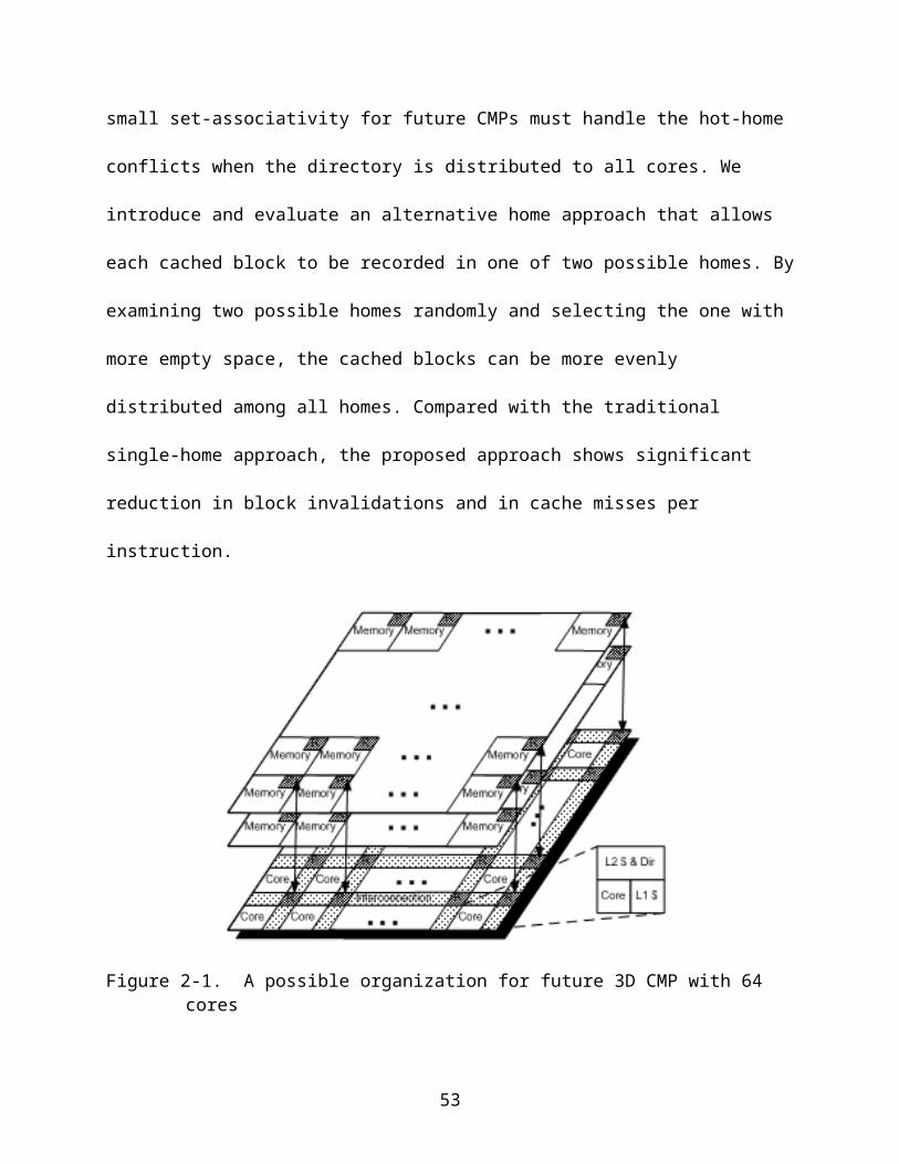
and is upgraded (replaced) by the parent prefix. When there is more than one MEP, all
the remaining MEPs are also invalidated. In case that no MEP exists in the cache, the
parent prefix is not cached.
3.4.2 A More Complicated Example
The prefix upgrade mechanism may not always upgrade an existing MEP to a
parent prefix. Figure 3.3 illustrate another trie example, where the parent prefix
<01*Port A> has two children, <010000000*Port B> and <010111*Port C>. When
a request <010000001…> arrives, the node <01000000*> is the last one visited and an
MEP <010000001*Port A> is cached. Next, when <010000000…> comes, it matches
<01*Port A> and then matches <010000000*Port B>. However, since the parent
<01*Port A> has more than one child, we cannot cache it with the child <010000000*
Port B> along. Nevertheless, we can cache <0100*Port A> with <010000000*
Port B> since <010000000*Port B> is the only child from the newly defined parent
<0100*Port A>. Now, because the MEP <010000001*Port A> is already in the
cache, we can upgrade it to the new upgradeable parent <0100*Port A>.
To create an upgradeable parent is straightforward during the trie traversal. After
the matched parent <01*Part A>, the upgradeable parent is moved to the node after a
node with both active left and right links in the traversal path. In Figure 3.3, for instance,
the upgradeable parent is moved from <01*Part A> to <0100*Port A> because the
node <010*> indicate there exists at least one child prefix in each of the left and the
right sub-tree. The largest cacheable sub-tree can only start from the first node after
<010*>.
53
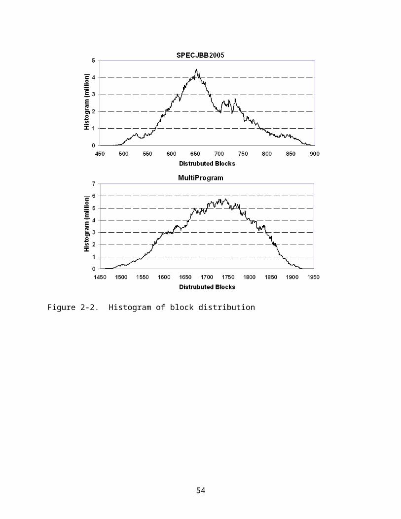
3.5 Handling Prefix Update
The prefix routing table is often changed during the running time. Although update
procedure of the prefix routing table separates from the general IP lookup and router
procedure, it is very important to consider the cache support of update operation during
the running time. As well as we need to update the trie, we also need to update the
cache so that later searching can see the update of the prefix table both in the cache
and in the trie. We consider the inserting and deleting operation separately. The
operation of changing the next hop info is just a combination of inserting and deleting
operation.
3.5.1 Prefix Insertion
Assume the inserted prefix is A <s*Part A>We can assume s is long enough
that it only can appear in one set. It is reasonable since most of the updates are
happens near the leaf level. If the inserted prefix may affect more than one cache sets,
the simplest solution is just flashing the whole cache. The cost will be negligible since it
happens very rarely.
As mentioned in [4], we need to check two IPs, s00...0 and s11...1, in the
corresponding set and update the cache based on the following four cases:
a.Both hit the same prefix B: Prefix A is a child prefix of B. Hence B must be disabled from the cache. If B is a leaf prefix, we need to disable the parent prefix of B also for LPM requirement.
b.Only one of the IP hits in the cached prefix B: Prefix A is the parent prefix of B. If B is not a leaf prefix, no change to the cache is needed. If the B is a leaf prefix, we need to check whether A is a child of the parent prefix PB of the B. If yes, PB needs to be disabled from cache.
c.The two IP hits the different prefix B and C: Prefix A is the parent prefix of both B and C. It is similar as b.
d.None of the IP hits in the cache: No change to the cache is needed.
54
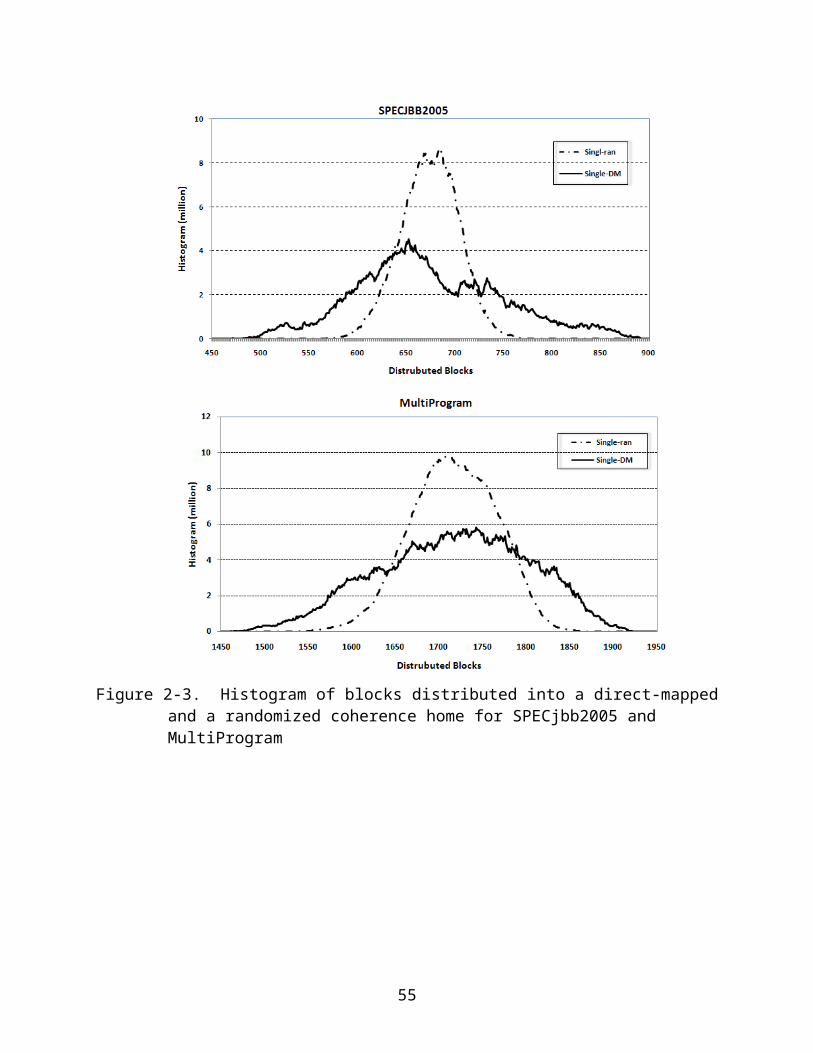
3.5.2 Prefix Deletion
It is more difficult to delete one prefix. When we need to delete a prefix, we don't
know it is a parent or leaf. We also don't know how many ME prefix it creates during the
previous searching procedure. The simplest solution is to flash all the sets the prefix can
appear. Since only one set will be affected when the prefix to be deleted is long enough,
this solution is fine for large number of sets. Another solution is to compare the next hop
of the effected sets and disable all the entries with the same next hop.
The prefix cache placement and replacement policies must be adjusted to
accommodate the parent prefix. First, a parent prefix must be placed in the same set as
its children so that the longest match requirement can be satisfied without additional
searches. Second, the children cannot be replaced before the parent. It is relatively
simple in handling the first requirement. As long as the set index comes from the high-
order bits of the IP address, the parent and children are naturally located in the same
set. This is true for the fact that we consider the prefix upgrade for parents with a single
child. Both the parent and the child are located closely to the leaf level. Furthermore, we
will show in the performance section that the prefix cache has severe conflict misses,
hence requires high set-associativity. The second requirement can be satisfied by
marking all the children prefixes when their parent is present in the cache. Instead of
replacing a marked child, any parent or MEP prefix closest to the LRU is replaced. One
extra bit is added for marking these children.
3.6 Performance Evaluation
We use the hit/miss ratios as the major parameter to evaluate the prefix cache
performance. The average routing decision time will be shortened if the hit ratio is
improved. As a result, the network processor can handle more incoming requests to
55
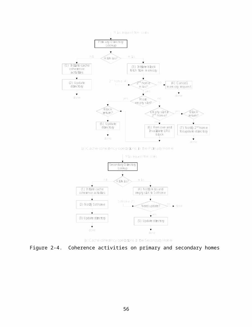
achieve higher throughput. In addition, upon a cache hit, the search through the trie can
be avoided; hence the power can also be saved.
To understand the general performance of the prefix cache, we first simulate the
MEP-only caches [3] with various sizes and set-associativities. The results are obtained
from simulating the 24-hour trace of MAWI [58] using the as1221 routing table[5]. The
trace contains 23.5 million addresses and the routing table has 215K prefixes. In figure
3.4, the miss ratios of three cache sizes with 256, 512 and 1024 prefixes are plotted.
The set-associativity starts with 16-way and continues all the way to fully-associative.
The results clearly indicate both the size and set-associativity are very essential to the
cache performance. As illustrated in Figure 3-3, the reuse distance was leveling off after
about 200, it is important to build large enough caches to capture the reuse of the
prefixes. Moreover, the results also show that the set-associativity is equally important.
The performance continues to improve almost all the way to fully-associative, especially
for small caches. In this study, we use the second domain ID (the 8th-15th bits) as the
index bits. With the wildcard in prefix, it is reasonable and necessary to index the set
using some higher-order bits from the IP address. Although more complicated cache
indexing algorithm with index randomization can be applied here, we found that the
impact to the overall cache performance is rather minor.
We now present the greedy prefix cache performance and compare it against the
MEP cache without caching the parent prefixes. Figure 3-5 shows the miss ratios of
both the MEP and the greedy caches for caches ranging from 128 to 512 prefixes. In
this simulation, we consider a fully-associative cache. We can observe that the upgrade
mechanism can reduce the miss ratio by about 6-8% for all cache sizes. Due to the fact
56
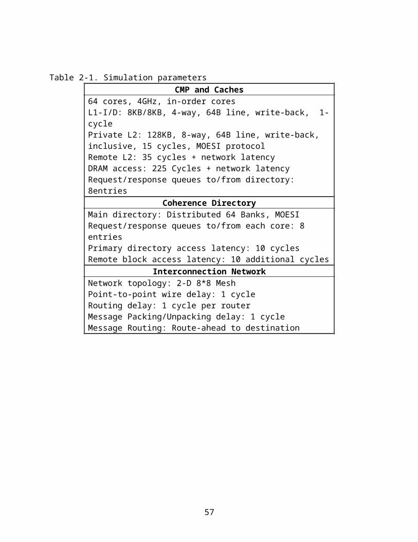
that more MEPs have a chance to be upgraded, the improvement is slightly better with
bigger caches.
With respect to set-associativity, we simulate the three cache sizes, 256, 512 and
1024 with different set-associativities for both the MEP-only and the greedy caches.
Again, from the results shown in Figure 3.6, set-associativity plays an important role in
helping the prefix upgrades. An improvement over 7% is possible with high set-
associvities. Due to severe conflicts in set-associative prefix caches, many MEPs are
replaced prematurely when the set-associativity is low. This conflict not only impacts the
hit/miss ratios as illustrated in Figure 3-4, it also reduces the benefit for upgrading the
MEP. Since high set-associativity is necessary to avoid conflicts, the upgrade scheme
works better under this circumstance
3.7 Summary
As the second work of this dissertation, a greedy prefix caching mechanism is
proposed. It improves the previous MEP approach [3] by caching the parent prefixes.
An existing MEP is upgraded to its parent prefix to expand the cache coverage when
the leaf prefix is also cached. The new greedy cache can be applied to existing trie-
based algorithms without any modification to the prefix routing table. The experiment
results show the proposed prefix caching mechanism achieves up to 8% miss ratio
improvement compared with the existing prefix caches.
57
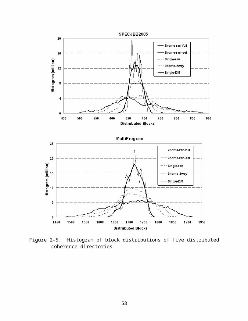
(a) (b) (c)
Figure 3-1. The trie and its variation: (a) Original tire, (b) Minimum expansion, (c) Split prefix
Table 3-1. The static and dynamic distribution of prefixesLeaf Parent Root Total
Static Distribution 200615 (93.1%)
14835 (6.9%)
1 (0.00%)
215451
Dynamic References
5.65M (24.0%)
8.98M (38.2%)
8.87M (37.8%)
23.52M
Table 3-2. Parent prefixes and MEPsChildren 1 2 3-10 >10
Parent 4611 3232 4667 2325
Total MEP 1480
0
7978 2624
9
83288
Average MEP 3.21 2.47 5.62 35.82
58
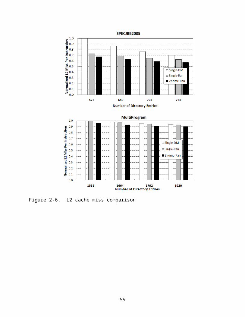
Figure 3-2. Reuse distances of Prefix-only and with MEP
Figure 3-3. An upgradeable parent on a trie
59
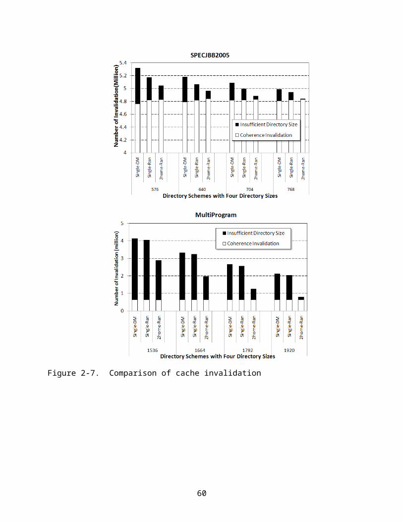
Figure 3-4. Performance impact of size and set-associativity on MEP-only caches
Figure 3-5. The miss ratio for MEP-only and MEP with upgrade
60
Figure 3-6. The Improvement of prefix upgrades compared to MEP-only
61
CHAPTER 4BANDWIDTH-EFFICIENT HASH-BASED NETWORK PROCESSOR
New generations of video, voice, high-performance computing and social
networking applications have continuously driven the development of novel routing
technologies for higher packet forwarding speeds in order to meet the future internet
demand. One of the fundamental design issues for high-speed core routers is fast
routing table lookup. Due to the increasing routing table size, the large routing table is
likely located in an off-chip memory, it is essential to provide sufficient memory
bandwidth to deliver constant lookup rate for satisfying the routing demand in future
network processors.
In the chapter, we develop several new hash schemes that can provide the nearly
optimal routing throughput by evenly distributing address prefixes into buckets. Evenly
distributed buckets minimize the maximum bucket size and can provide a constant
lookup rate with minimal memory bandwidth requirement. The chapter is organized as
follows. The motivation is shown in 4.1 while related works are discussed in 4.2. The
existing hash approaches are reviewed in 4.3. The first scheme that we proposed,
Deterministic Multi-Hashing (DM-Hash) is described in 4.4. 4.5 discuss the ways to
satisfy the longest prefix match requirement and the prefix table updates are discussed
in 4.6. 4.7 and 4.8 discussed the improved schemes, Selective Multiple Hashing (SM-
Hash) and Two-Step-Hashing (TS-Hash). The experiment results are shown in 4.9 while
the summary is in 4.10.
4.1 Problem and Challenge
A high-speed router needs two algorithms to perform efficient packet forwarding.
The setup algorithm organizes the routing table information in an indexing data structure
62
to enable fast lookup. The lookup algorithm searches the indexing structure for the
address prefix that matches a given destination address. Each prefix in the indexing
structure is stored together with the routing information, including the outgoing network
interface and the IP address of the next hop router.
In this chapter, we consider the hash-based indexing structure. Suppose we have
n address prefixes that are hashed to m buckets, each occupying a fixed size of
memory that can store a certain number of address prefixes and the corresponding
routing information. For now, we assume all prefixes have the same length. Prefixes
with different lengths will be addressed in Section 4. When the router receives a packet,
it extracts the prefix of the destination address and hashes the prefix to find the relevant
bucket. The bucket is retrieved to the network processor chip (NPC) from an off-chip
SRAM. The NPC searches the bucket for the prefix and the associated routing
information, based on which the packet is forwarded. Some hashing schemes require
fetching multiple buckets to route a packet [16, 28].
The operation that the NPC performs to search a bucket for a given prefix can be
made very efficient through hardware pipelining. The bottleneck that limits the routing
throughput is the communication from the SRAM to the NPC. Because the NPC
continuously processes the arrival packets, its hashing and searching operations for
some packets overlap with the fetch of SRAM data for other packets. Therefore, the
routing throughput is entirely determined by the bottleneck operation. Let B be the
maximum bandwidth at which the NPC can fetch data from the SRAM and s be the
bucket size. If the NPC needs to fetch k buckets in order to forward a packet, then the
routing throughput is bounded by Bks packets per second.
63

The problem is to minimize ks in order to maximum the routing throughput. The
minimum number of buckets that the lookup algorithm needs to fetch is one. Let l be the
number of bits it takes to store a prefix and its associated routing information. The
minimum value of s is nlm , in which case the prefixes are evenly distributed among the
buckets. When both the number of fetched buckets and the size of each bucket are
minimized, the routing throughput is maximized at mBnl . However, as we will
demonstrate next, minimizing both of the above quantities is a difficult task that has not
been accomplished in the prior literature.
4.2 Related Works
There are three categories of LPM approaches including Ternary Content
Addressable Memories (TCAM)[4, 26, 53, 59, 71, 91], trie-based searches[27, 30, 35,
39, 43, 47, 54, 73, 74, 81, 86], and hash-based approaches[16, 28, 29, 34, 48, 79, 80].
TCAMs are custom devices that can search all the prefixes stored in memory
simultaneously. They incur low delays, but require expensive tables and comparators
and generate high power dissipation. Trie-based approaches use a tree-like structure to
store the prefixes with the matched output ports. They consume low amount of power
and less storage space, but incur long lookup latencies involving multiple memory
operations that make it difficult to handle new IPv6 routing tables. Although a small
cache can be added to the trie-based approaches [3, 20, 21, 51, 52] to improve the
average latency and throughput, the latency for the worst case are still huge.
Hashed-based approaches store and retrieve prefixes in hash tables. It is power-
efficient and is capable of handling large number of prefixes. However, the hash-based
64
approach encounters two fundamental issues, hash collisions and inefficiency in
handling the LPM function. Sophistic hashing functions [36] can reduce the collision
using expensive hardware with long delays. Multiple hashing functions allocate prefixes
into the smallest hashed bucket for balancing the prefixes among all hashed buckets [6,
15, 16]. Cuckoo [28] and Peacock [48] multiple-hashing schemes further improve the
balance with relocations of prefixes from long buckets. The downside of having multiple
choices is that the searches must cover multiple buckets. Extended Bloomier Filter [79]
places each prefix into multiple buckets and uses a counter to count the number of
prefixes in each bucket. Searches are only needed from the shortest bucket. To reduce
the space overhead and the length of the buckets, duplicated prefixes are removed. For
efficient searches, proper links with shared counters must be established.
Handling LPM is difficult in hash-based routing table lookup. To reduce multiple
searches for variable lengths, Control Prefix Expansion (CPE) [86] and its variances
[28, 80] reduce the number of different prefix lengths to a small number with high space
overhead. The tradeoff is that the lookup algorithm will search a fewer number of
prefixes at the expense of a much expanded routing table.
Organizing the routing table in a set-associative memory and using common hash
bits to allocate different lengths prefixes into the same bucket reduces the number of
memory operations to perform the LPM function [28, 41, 42]. However, by coalescing
buckets with multiple prefix lengths, it creates significant hashing collisions and hence
increases the bandwidth requirement.
Bloom Filter [11] was considered to filter unnecessary IP lookups of variable prefix
lengths [29]. Multiple Bloom filters are established, one for each prefix length to filter the
65
need in accessing the routing table for the respective length. Due to uneven distribution
of the prefix lengths, further improvement by redistribution of the hashing functions and
Bloom filter tables can achieve balanced and conflict-free Bloom table accesses for
multiple lengths of prefixes [80]. In these filtering approaches, however, the false-
positive condition may cause unpredictable delays due to multiple additional memory
accesses. In addition, even though Bloom filters are relatively compact data structures,
they still represent significant overhead to the cache memory of the network processor if
the false positive ratio is required to be low.
Chisel [34] adopts the Bloomier filter [18] for its indexing structure. It requires a
large indexing table to achieve conflict-free hashing. Because each prefix must be
hashed to a singleton entry and each entry in the indexing table can serve as a
singleton for only one prefix, the table size must be larger than the number of prefixes in
the routing table. The former is typically chosen between 1.5 and two times of the latter.
Each indexing entry is at least 20 bits long to encode the IDs of up to 1 million buckets.
Each routing table entry in SRAM is about 8 bytes long, three for address prefixes, one
for output port, and four for next-hop address. Hence, the size of the indexing table in
Chisel is between 46.9% and 62.5% of the routing table, making it too large to fit in the
on-chip cache memory. Our DM-hash scheme does not require that each prefix must be
mapped to a singleton entry. It thus eliminates the hash collision problem and can work
with an index table of any size.
4.3 The Existing Hashing Approaches
It is well known that a single hash function cannot evenly distribute prefixes in the
buckets [6]. We perform a simulation with n=1000,000 and m=300,000. We assign IDs
from 0 to m−1 to the buckets. Each prefix p is stored at a bucket whose ID is H ( p),
66

where H (…) is a hash function with a range of ¿. The distribution of the prefixes among
the buckets is presented in the left plot of Figure 1. The plot shows that some buckets
hold much more prefixes than others. The largest number of prefixes that a bucket has
to hold (denoted as Ω) is 15, which is 4.5 times the average number, n /m.
Unfortunately, the bucket size s is determined by Ω. It has to be as large as Ωl in order
to avoid overflowing. In this case, the routing throughput will be only one fifth of the
optimal value. Moreover, the total memory consumption is sm, which increases linearly
in the value of s.
In the next sections, we summarize the existing hash approaches for the balance
the distributions. One straightforward approach is using the non-deterministic multi-
hashing, which is presented in 4.3.2 and more complicated perfect hash approaches
are presented in 4.3.3.
4.3.1 Single Hash
Although approaches using a single general hash function only need to fetch one
bucket, the bucket sizes are usually large. The bucket size of a general hash function
which maps n keys into m buckets is Θ( lnm
ln ⌈1+mnln n ⌉
+ nm
) as shown in [25]. As shown
in Figure 4.1, when m = 300,000 and n = 1000, 000, the bucket size is about 15 which is
the average of 1,000 simulations. It is 3.75 times larger than the optimal size, which is 4.
The large bucket size makes the single hash approach not suitable for IP-lookup.
4.3.2 Non-Deterministic Multi-hashing Schemes
To solve the uneven distribution problem, one main method adopted in the prior
research is to use multiple hash functions. Let H 1( p),… , H k ( p) be k different hash
67

functions. The setup algorithm decides the placement of the prefixes sequentially. When
processing a prefix p, it uses the hash functions to map the prefix to k buckets whose
IDs are H 1( p),… , H k ( p). It then stores p in the bucket that currently has the fewest
number of prefixes. As shown in the bottom plot of Figure 4.1, when we use more hash
functions, the prefixes are more evenly distributed among the buckets and the value of
Ω decreases, which means a smaller bucket size.
Using the above idea, various sophisticated multi-hashing schemes were
proposed to minimize the bucket size [6, 15, 16, 28, 48]. Suppose we use d hash
functions. Each prefix is hashed to d buckets and the prefix is placed into the bucket
currently having the fewest prefixes. Azar et al. proved that the bucket size can be
reduced to (1+∘ (1 ) )× ln lnmlnd+Ω( n
m) in [6]. Vocking proposed d-left hash that further
reduces the bucket size by using an Always-Go-Left algorithm for tie-breaking [90].
Cockoo hashing [14] uses two hash functions and allows the prefixes already placed in
a bucket to be moved to other buckets in order to create room for new prefixes.
Those approaches are called non-deterministic muti-hashing (NM-hash) schemes
because we do not know exactly which bucket a prefix is stored even though we know
that it must be one of the k buckets that the prefix is mapped to. Hence, the lookup
algorithm has to fetch all k buckets and the NPC searches them in parallel. Even at the
optimal bucket size nlm , the routing throughput is reduced to
mBknl , which is one k th of the
optimal. The dilemma is that in order to reduce s (the bucket size) for better routing
throughput, we have to increase k (more hashing functions), which however will reduce
the routing throughput.
68

4.3.3 Perfect Hash Function
A collision-free hash function is also called “perfect” hash function. A hash
function h is perfect if for any two different keys in the key set, their hashing values are
different. Prefect hash function is also called “one-probe hash” since it only requires
exactly one hash table access.
Although perfect hash is very useful for many applications such as database,
compiler, network etc, finding a perfect hash is extremely difficult. The perfect hash
works only for one key set and if the key set is changed, the function must be changed.
Knuth discussed the perfect hash function for m=41 and n=31 in [44].
"Unfortunately it isn't very easy to discover such functions f(K). There are 4131≈1050 possible functions from a 31-element set into a 41-element set,
and only 41×40×…×11=41 !10 !
≈1043 of them will give distinct values for each
argument; thus only about one of every 10 million functions will be suitable." "In fact it is rather amusing to solve a puzzle like this."
The perfect hash function attracts research interests in the last two decades [14,
23, 24, 32]. Most recent perfect hashing approaches requires O(nlogn) space overhead.
However, their approaches cannot be directly applied for our task where m<n.
4.4 A Novel Deterministic Multi-hashing Scheme (DM-hash)
In this section, we propose a deterministic multi-hashing scheme to distribute the
prefixes in the buckets for near optimal routing throughput.
4.4.1 Deterministic Multi-hashing
In our deterministic multi-hashing (DM-hash) scheme, the setup algorithm uses
multiple hash functions to decide where to place a prefix (which may end up in any of
the m buckets), yet the lookup algorithm has the information to determine the exact
69
bucket where the prefix is stored. No prior work has investigated deterministic multi-
hash schemes before. Below we give a design overview of our DM-hash scheme.
Because a prefix may be stored in any of the m buckets, we must store some
information for the lookup algorithm to know which bucket it actually resides. The
simplest solution is to build an index table that has an entry for each prefix, keeping the
ID of the bucket where the prefix is stored. However, this naïve approach does not work
because the table must be stored on the NPC where the lookup algorithm is executed,
but the size of the table is too big to fit on the NPC. We must reduce the size of the
index table, which means that each table entry has to encode the mapping information
for multiple prefixes.
DM-hash is designed to work with any table size, which contrasts with Chisel’s
requirement of more than n entries [34] due to a fundamentally different design. Let x (
≪m) be the number of entries in the index table. In DM-hash, each entry is an integer of
log2m bits long, where m (the number of buckets) is chosen to be a power of 2. Instead
of mapping each prefix directly to the buckets as the previous schemes do, we map
each prefix to k entries of the index table. The XOR of the k entries gives the ID of the
bucket in which the prefix will be stored; in order to improve the mapping randomness,
we may also use the hash of the XOR result for the bucket ID. Hence, the hash function
for the DM-Hash can be presented as follows:
h ( p )=v ( g1 ( p ) )⊕ v (g2 ( p ) )⊕…⊕v (gk ( p )), whereg1 (p ) , g2 (p ) ,…, gk ( p ) are the k hash
functions that map the prefix to the index table and v (i) is the value stored in the i-th
entry in the index table.
70
Because the index table is small and located on chip, its access is much faster
than the bottleneck of off-chip memory access. Each different way of setting the values
for the x entries in the index table results in a different assignment of the prefixes to the
buckets. There are mx different ways, which represent a large space in which we can
search for a good setup of the index table for balanced prefix distribution. The key
challenge is how to find a good setup of the index table without exhaustively searching
all mx possible ways. Our solution is described below.
The setup algorithm of the proposed DM-hash scheme divides the n prefixes intro
x disjoint groups, denoted as G1 ,G2 ,…,G x. Each prefix in Gi is mapped to k entries in
the index table, which is called the hash neighborhood of the prefix. The union of the
hash neighborhoods of all prefixes in Gi forms the hash neighborhood of the group,
denoted as N i,1≤i ≤ x. We sort the entries of the index table in a so-called progressive
order, denoted as e1 ,e2 ,…,e x, which has the following properties. Let Ei = e1 ,…,e i.
The first property is that e i must be in the hash neighborhood of any prefix in Gi, 1≤i ≤ x.
The second property is that Ei contains the hash neighborhood of Gi, namely, N i⊆E i.
We will explain how to divide prefixes into groups and how to establish a progressive
order in Section 4.4.2.
Unlike the NM-hash schemes [6, 13, 15, 16, 28] that map one prefix to the buckets
at a time, our setup algorithm maps a group of prefixes to the buckets at a time.
Following the progressive order, the algorithm sequentially assigns values to the entries
of the index table. Suppose it has assigned values to entries in Ei−1 and the next entry
to be assigned is e i. Based on the properties of the progressive order, we know that the
placement of prefixes in groups G1 ,…,G i−1 has already been determined. The ID of
71

the bucket in which a prefix in Gi will be placed is the XOR of e i with (k−1) other entries
in Ei−1. Therefore, once we assign a value to e i, the placement of all prefixes in Gi will be
determined. The entry e i may take m possible values (from 0 to m−1). Each value
results in a different placement of the prefixes in Gi to the buckets. The setup algorithm
will choose the value that achieves the best balanced distribution of prefixes in the
buckets (see Section 4.4.3 for details). The algorithm repeats the process until the
values of all entries are chosen.
In the DM-hash scheme, the lookup algorithm hashes the prefix extracted from a
destination address to k entries in the index table, and then it XORs the entries to
identify a bucket, which will be fetched from the SRAM to the NPC. The setup algorithm
maps a group of prefixes to the buckets at a time. It tries m different ways to find the
best mapping for a group. In the NM-hash schemes, the lookup algorithm hashes the
prefix directly to k buckets, which will be fetched. Their setup algorithms map one prefix
to the buckets at a time. They try k different ways to find the best mapping for the prefix.
Both DM-hash and NM-hash schemes do well in balancing the numbers of prefixes
stored in the buckets. Their Ω values can be made close to the optimal, n /m. Their
memory overhead can thus be made close to the optimal, m× nml=nl. However, the DM-
hash scheme only requires fetching one bucket. Hence, its routing throughput is also
close to the optimal value of mBnl .
The additional overhead for the DM-hash scheme is a small on-die index table of
size x log2m, where x can be made much smaller than m (see Section 4.4.4).
72

4.4.2 Progressive Order
DM-hash maps each prefix to k entries in the index table. The set of prefixes that
are mapped to an entry is called the associated group of the entry. Clearly, an entry is in
the hash neighborhood of any prefix in its associated group. If we look at the associated
groups of all entries as a whole, each prefix appears k times in them. The problem is to
remove prefixes from groups such that (1) each prefix appears exactly once in the
groups and (2) when we put the entries in a certain order, their associated groups will
satisfy the properties for progressive order.
We present a simple algorithm to solve the above problem: Randomly pick an
entry as ex and remove the prefixes in its current associated group G x from all other
groups. Then, randomly pick another entry as ex−1 and remove the prefixes in its
associated group G x−1 from all other groups. Repeat the same operation to randomly
select entries ex−2, …, e1, and construct G x−2, …, G1. Finally, reverse the order of the
entries. The resulting sequence, e1, …, ex, together with their associated groups,
represents a progressive order. This can be proved as follows: Consider an arbitrary
entry e i and an arbitrary prefix p in Gi. Based on the initial construction of Gi, we know
that e i must be in the hash neighborhood of p. We prove the hash neighborhood of p is
a subset of Ei by contradiction. Suppose the neighborhood of p contains e j, where j>i.
Hence, p is initially in G j. When e j is selected, p is removed from the associated groups
of all other entries and therefore p must not be in Gi, which leads to the contradiction.
Because the hash neighborhood of p is a subset of Ei for any prefix p in Gi, it must be
true that N i∈Ei. This completes the proof.
73

We can improve the above algorithm to balance the group sizes. During the
execution of the algorithm, as we remove prefixes from groups, the group sizes will only
decrease. Hence, whenever the algorithm selects an entry as e i, instead of randomly
picking one (that has not been selected before), it should choose the entry whose
associated group has the fewest number of prefixes. Otherwise, if this entry is not
chosen for e i but for e jlater where j>i, then the size of its associated group (which is
already the smallest) may decrease further.
4.4.3 Value Assignment for the Index Table
The setup algorithm sequentially assigns values to the entries in the index table in
the progressive order. When it tries to determine the value of an entry e i, the algorithm
iterates through all possible values from 0 to m−1. Each possible value corresponds to
a different way of placing the prefixes in Gi to the buckets. We define the bucket-load
vector as the numbers of prefixes in the m buckets sorted in the descending order. Each
possible value of e i results in a bucket-load vector (after the prefixes in Gi are placed in
the buckets based on that value). The m different values for e i result in m bucket-load
vectors. The setup algorithm will choose a value for e i that results in the min-max vector,
which is defined as follows: Its first number (i.e., the largest number of prefixes in any
bucket) is the smallest among all m vectors. If there is a tie, its second number (i.e., the
second largest number of prefixes in any bucket) is the smallest among the vectors tied
in the first number … If there is a tie for the first j numbers, its ( j+1)th number is the
smallest among the vectors tied in the previous numbers. The min-max vector not only
has the smallest value of Ω but also has the smallest difference between the largest
number of prefixes in any bucket and the smallest number of prefixes in any bucket.
74

There are x entries. For each entry, the setup algorithm tries m values. For each
value, a bucket-load vector is sorted in time O(m logm). Finding the min-max vector
among m bucket-load vector takes O (m2 ) time. Hence, the time complexity of the setup
algorithm is O (x× (m×m logm+m2 ))=O(xm2 logm).
4.4.4 Analysis
How large should the index table be? We answer this question analytically and
support the result with simulation. Let δ i (δ i+1 ¿be the average number of prefixes in a
bucket and Ωi (Ωi+1¿ be the large number of prefixes in any bucket after the setup
algorithm determines the value of e i (e i+1)and the prefixes in Gi (G¿¿ i+1)¿ are placed in
the buckets. Let g be the number of prefixes in Gi+1. Given the values of δ i, Ωi and g as
input, we treat Ωi+1, which is the outcome of the setup algorithm once it determines the
value of e i+1, as a random variable. Our objective is that whenever Ωi−δi≥1, the
subsequent operation of the setup algorithm will make sure that E (Ωi+1−δ i+1 )<(Ωi−δ i).
Hence, the expected largest number of prefixes in any bucket is controlled within one
more than the average number.
Let q be the percentage of buckets that hold no more than δ i prefixes. We know
that the m possible values for e i+1 result in m different ways of placing the g prefixes in
Gi+1 to the buckets. To make the analysis feasible, we treat them as m independent
random placements of the prefixes. As we will see, such approximation produces
results that match what we observe in the simulation. The probability for one placement
to put all g prefixes only in buckets currently having no more than δ i prefixes is qg. The
probability for any one of the m placements to do so is 1−(1−q¿¿g)m¿. When this
happens, Ωi+1=Ωi; otherwise, Ωi+1≤Ωi+1. We expect that m is chosen large enough
75
such that g≪m and thus the probability for two prefixes in Gi+1 to be placed in the same
bucket that has the largest number of prefixes is negligibly small. Hence,
E (Ωi+1 )≤ (1−(1−qg )m )Ωi+(1−qg )m (Ωi+1 )=Ωi+(1−qg)m.
Because δ i+1=δi+gm , we have
E (Ωi+1−δ i+1 )≤Ωi−δ i+(1−qg)m− gm.
Hence, our objective is to satisfy the inequality, (1−qg)m− gm
<0. Approximately, we
let q=12 and ≤
nx , which means that about half buckets are loaded with an average
number of prefixes or below, and that Gi+1 has about the average number of prefixes
among all groups. The inequality becomes
m( 12)nx >−ln n
xm.
When n=1,000,000 and m=300,000, the value of x is around 67,180. It agrees with
our simulation result in Figure 2, where Ω=5. The value of Ω is the closest integer that
is larger than one plus the average, n /m, which is 3.33.
4.5 Longest Prefix Match with DM-Hash
Given the requirement for matching the longest prefix, each routing table lookup
must search for all possible prefix lengths. It incurs long delays for sequential searches
or a huge bandwidth requirement for parallel searches. The Control Prefix Expansion
[86] limits the number of prefix lengths by expanding the table size. Based on our
simulation using a few selected routing tables, the table size is expanded to 4 and 10
times when the number of prefix lengths is limited to 3 and 2 respectively. In an
opposite approach for eliminating multiple searches, variable lengths of prefixes can be
76
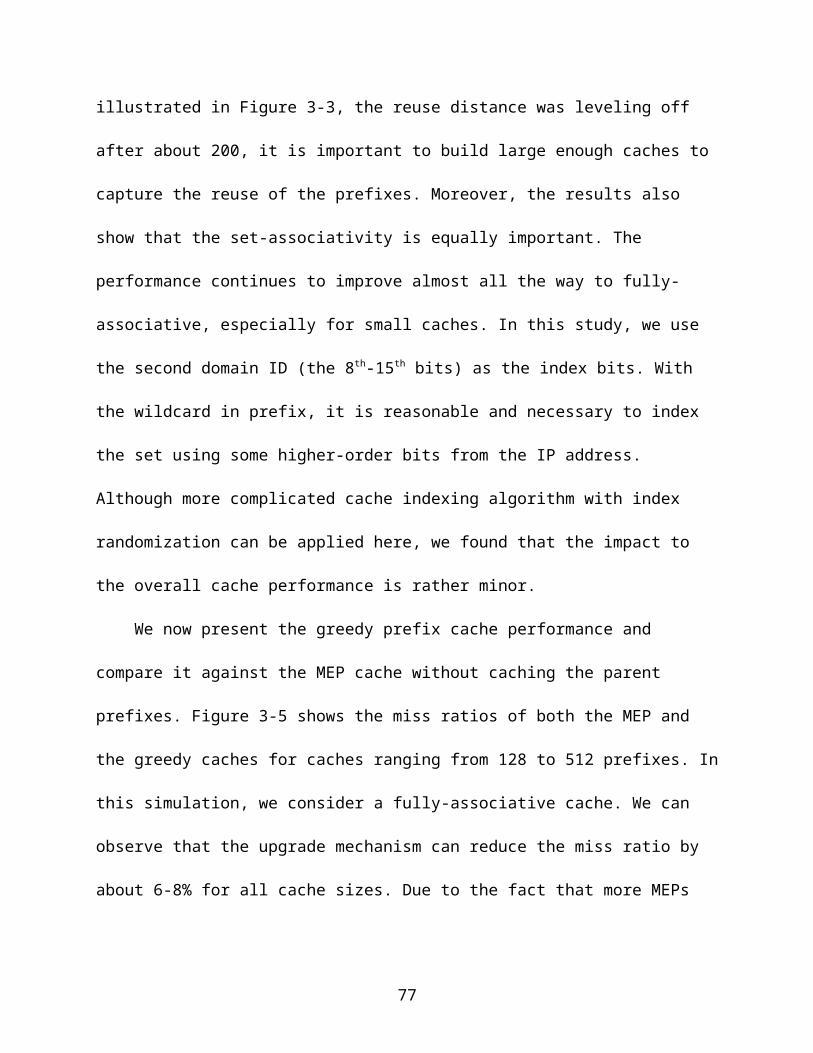
coalesced into one bucket using common hash bits to decide the hashed bucket [28,
41, 42]. This approach, however, suffers heavy collisions due to the constraint of
obtaining the common hash bits from the shortest prefix length.
In our study, we use two mechanisms to satisfy the longest prefix match
requirement. The first is a two-level LPM mechanism, which partitions all the possible
prefix lengths into three groups. The main LPM scheme selects up to one longest prefix
from each group and compares the lengths of the three selected prefixes and figure out
the longest one among the three selected prefixes. The two small groups are placed in
on-chip TCAM to avoid searching the off-chip SRAM. By using the two-level partition,
the number of lengths that needs to be stored off-chip is greatly reduced and the
number of the off-chip accesses for each lookup is consequentially reduced.
The second mechanism we used is the hybrid prefix expansion/coalescing
scheme, which is applied to the largest group. The controlled prefix expansion (CPE)
can expand the short prefixes into longer ones with the cost to increasing the prefix
table size. On the other hand, the coalescing approach presented in [42] uses fewer bits
for different lengths with the cost to increase the chance of collisions in the hashing
table.
4.5.1 Two-level Partition
As many researchers already pointed out, the distribution of the prefix lengths are
very uneven in the IPv4 routing tables. The length distributions of five largest routing
tables are shown in Table4-3. The prefixes with length 24 occupies about 54% and
most of the prefixes have the length between 19-24 (over 90%).
In our design, we partitioned the prefixes into three groups, length 8-18, length 19-
24, and length 25-32, based on the prefix distribution. The group of length 8-18 contains
77

11 different lengths but only <9% prefixes and the group 25-32 contains 8 different
lengths but very few prefixes (<1%). So both groups are very suitable to be placed on a
on-chip small TCAMs, as shown in Figure 4-6. Finding the longest prefix in the TCAM is
a well studied problem and the solutions in [3, 60, 63] can be applied here.
The rest six lengths from 19 to 24 contain most of the prefixes and needs to be
stored in off-chip SRAM. We use the hash table based on our DM-Hash scheme to
store those prefixes.
The two-level longest match scheme reduces the number of lengths that needs to
be fetched from off-chip memory. Among all the possible 25 lengths (8-32), only 6 of
them (19-24) need to be fetched from off-chip. In the next subsection, we will show you
how to get the longest prefix of the 6 lengths with only one memory access.
4.5.2 Partial Prefix Expansion
The prefixes in the length group 19-24 need to be stored in the off-chip SRAM.
The longest prefix in the group needs to be determined for each packet. The basic
solution is to search all the six possible lengths. Searching for each length will results in
at least one routing table access.
One straightforward solution to avoid search all the possible lengths is to expand
all prefixes to the maximum length 24. This approach is known as the Controlled Prefix
Expansion (CPE) approach [86]. Such an expansion produces significant space
overhead as shown in Figure 4.4. The other opposite solution is to keep all prefixes
without any expansion. Multiple lengths of prefixes that are required for determining the
LPM can be allocated in the same bucket based on the common 19 prefix bits for
accommodating the shortest length. Although this bucket coalescing approach achieves
78
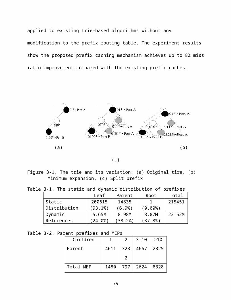
one memory access per lookup, it suffers heavy bandwidth requirement since all
prefixes must be hashed to buckets based on only the 19 common bits.
Instead of the previous approaches, we use a hybrid approaches named partial
expansion, which combines the expansion and coalescing. Now consider a general
case where all prefixes have lengths from m to n with n−m+1 different lengths. To
accomplish one memory access per lookup, a fixed length l, m≤l ≤n can be chosen for
balancing the space overhead from prefix expansion with the bandwidth requirement
due to coalescing of different lengths into the same bucket. All prefixes with lengths less
than l are expanded to l for determining the hashed bucket. By reducing the expansion
from lengths n to l, the expansion ratio can be reduced up to a factor of 2n−l. However,
in using the common l bits for hashing, a maximum of 2n−l prefixes may now be
allocated in the same bucket. We refer to this collision as the lower bound of the
maximum number of prefixes in a bucket. For example, with about 70% of space
overhead, we can expand length 19-21 to 22 to be used for hashing. With this
expansion, however, the lower bound for the maximum bucket length becomes 4.
Similarly, in order to reduce the lower bound to 2, we must expand prefixes 19-22 to 23
with about 2.7 times of the prefixes. Note that besides the collision due to limited
hashing bits, the maximum length in a bucket is determined by the overall hashing
collisions since prefixes with different common bits may still be hashed into the same
bucket.
4.6 Handle Prefix Updates
There are three types of updates to a hash table, 1) adding new prefixes, 2)
deleting existing prefixes, 3) modifying the routing information of an existing prefix. As
79
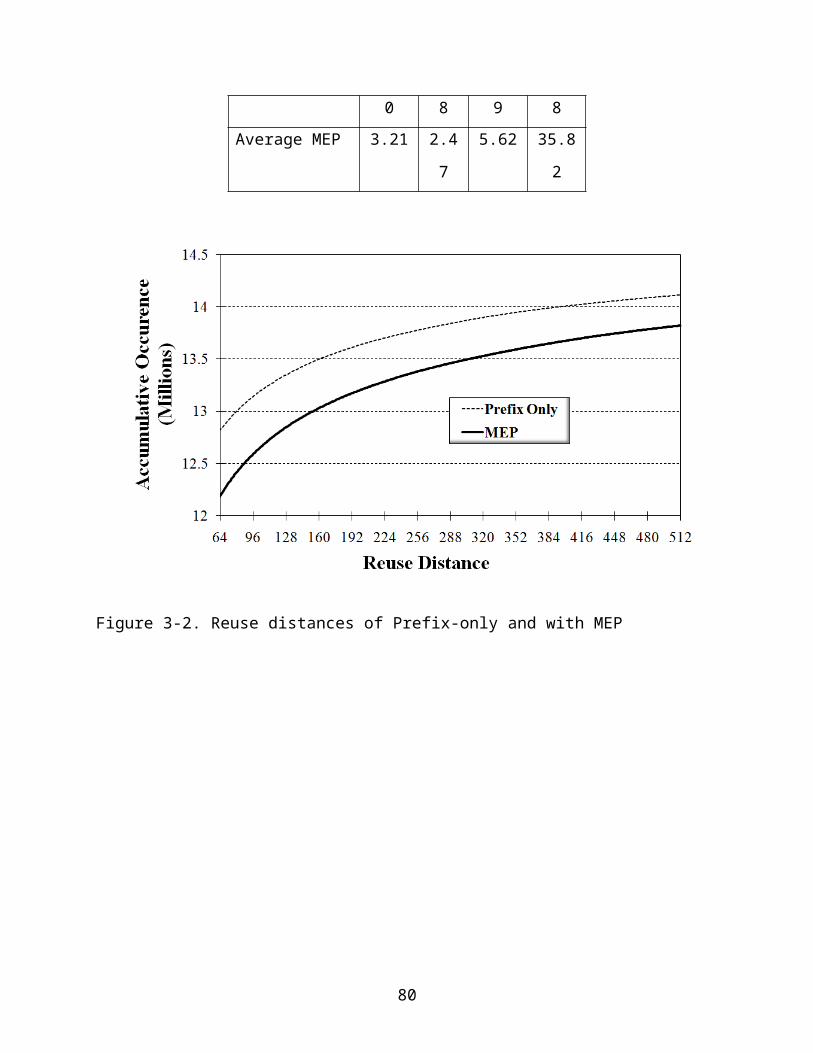
we discussed in the previous section, the prefixes with length 8-18 and 25-32 are stored
in the on-chip TCAM. The updates to those prefixes can be handled by the TCAM
solutions as presented in [3, 60, 63]. In this section, we only discuss the updates to the
prefixes with length 19-24. We first discuss how to insert or delete a prefix which doesn't
require expansion and then discuss how to consider the expansion with updates.
4.6.1 Insert New Prefixes
Adding a new prefix is the most complicated task for DM-Hash based routing table
updates. Although when adding a new prefix, we can decide which bucket the new
prefix should go by exclusive-oring the k entries the new prefix is hashed to in the index
table, the hashed bucket for the new prefix may already contain the maximum prefixes
that the memory bandwidth can handle. Adding new prefixes into a full bucket will
prevent the bucket from being fetched in time to sustain the network throughput
requirement.
In this case, a straight-forward solution is to re-setup the whole index table.
However, re-setup is costly and not suitable for frequent prefix additions in the routing
table. One reasonable solution is to allow minor modification in the index table to avoid
the bucket overflow. However, adjusting an index table entry affects multiple prefixes
that have already been placed into the hash buckets.
We add one more data structure named index mapping table for DM-Hash to
handle the updates as shown in Figure 4-6. The index mapping table records the
prefixes that are mapped to each index table entry during the setup as the prefix
subgroup Gi for each 0≤ i≤ x−1. The index mapping table can be stored on slower
memory units since it is only accessed when a prefix is added or removed.
80
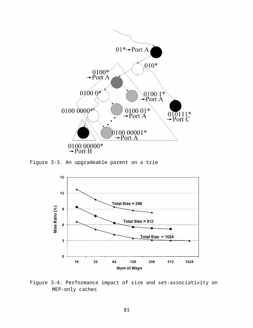
The procedure to add a new prefix p works as follows. First, we calculate the h( p)
using the current values stored in the index table. If the bucket indexed by h( p) still has
room to hold the new prefix, the new prefix is added to the bucket and the addition of a
prefix finishes. Otherwise, we try to modify the index table entry e (g1 (p )) to place all
prefixes into the buckets. The prefix subgroupG(g1 ( p )) is fetched from HIT Mapping
Table. We set a new value for the entry e (g1 (p )) and check whether the new prefix pand
all the prefixes in G(g1 (p )) can find a room in the new buckets indexed by the new
hashing function. If successful, we modify the e (g1 (p )) to the new value, move all the
prefixes in G(g1 (p )) to the new buckets, and add prefix p into its buckets. If all the
possible values of e (g1 (p )) are failed, the entry e (g2 (p )),…,e (gk ( p )) are tried. If all the
entries are failed, the index table re-setup procedure is invoked.
However, re-setup the entire index table is still costly. Inspirited by the Chisel
paper [34], we add another small on-chip TCAM to store the overflowed prefixes to
avoid the re-setup procedure. As we show in the experiment section, a small TCAM is
sufficient to hold the overflowed prefixes.
4.6.2 Delete or Modify Existing Prefixes
The deletion and modification for the DM-Hash are more straightforward. When
deleting an existing prefix p, it goes to the bucket determined by h( p) using the existing
values in the index table, finds and deletes the prefix in the bucket, and remove p from
the G (gi (p ) ) ,1≤i ≤ k in the index mapping table. When modifying a prefix p, it finds the p
in the bucket determined by h( p) and does the necessary modification.
81
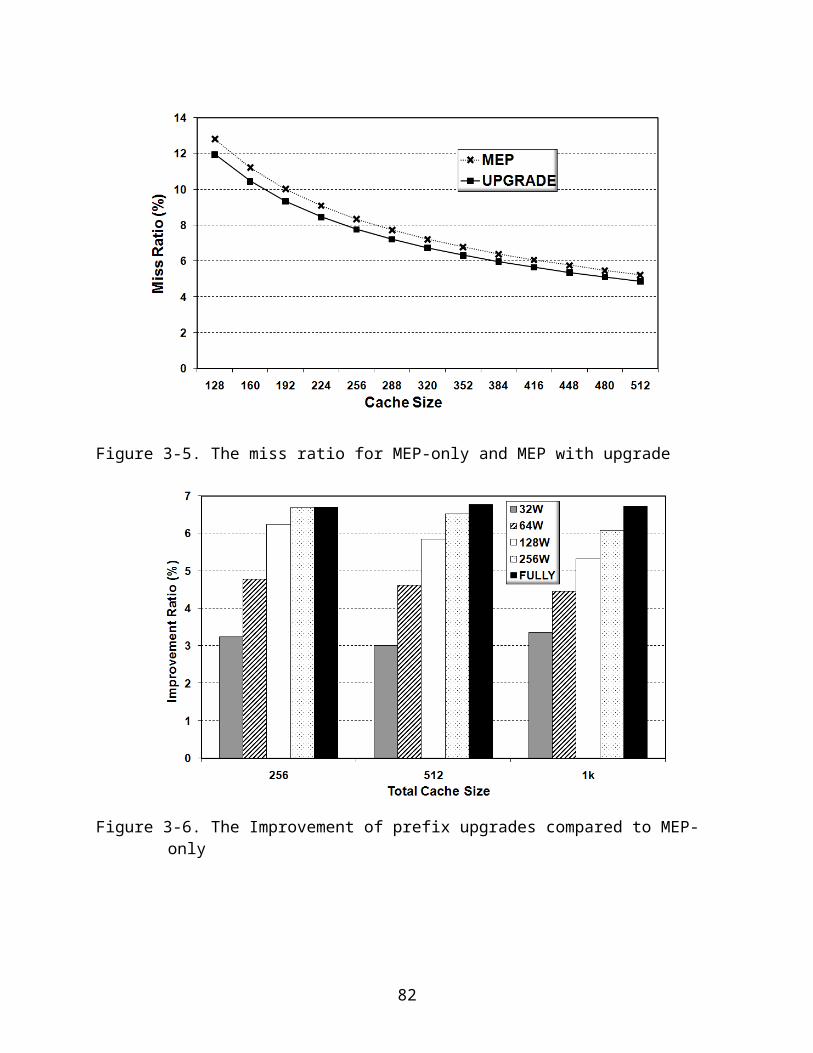
4.6.3 Updates with Partial Prefix Expansion
As discussed in the earlier section, the prefixes with six different lengths, 19-24, are
stored in off-chip SRAM. In order to avoid search all the six lengths, the partial prefix
expansion is applied and only one bucket from SRAM needs to be fetched and
compared. However, the partial prefix expansion complicates the process of routing
table updates.
Since the partial prefix expansion expands a short prefix to several longer prefixes
and stores the expanded prefix instead, the updates to the short prefix should be taken
care of in the similar way. It means when we need to insert a short prefix, for example a
prefix whose length is 19, we need to expand the prefix to 16 22-bit prefixes (if we
expanded to 22 bits) or 32 23-bits prefixes (expanded to 23 bits) and insert the
expanded prefixes instead. The modifications and deletions to the existing short
prefixes are handled in the similar way.
4.7 Selective-Multiple Hashing (SM-Hash)
Although DM-Hash can achieve very balanced hashing results, it requires a
complicated setup mechanism which is time costly. In order to simplify the setup, we
proposed two improved hash function approaches named Selective Multiple Hashing
(SM-Hash) and two-step hashing (TS-Hash) in this section and the following section.
As discussed before, the buckets are unbalanced if only a single general hash
function is applied. The buckets can be well balanced if we use multiple hash functions.
Similar as what we do in the DM-Hash, we want to keep the freedom to place one prefix
into multiple locations but only fetching one bucket when searching for a prefix. We also
use the on-chip index table which records the hash function which is selected for each
prefix.
82
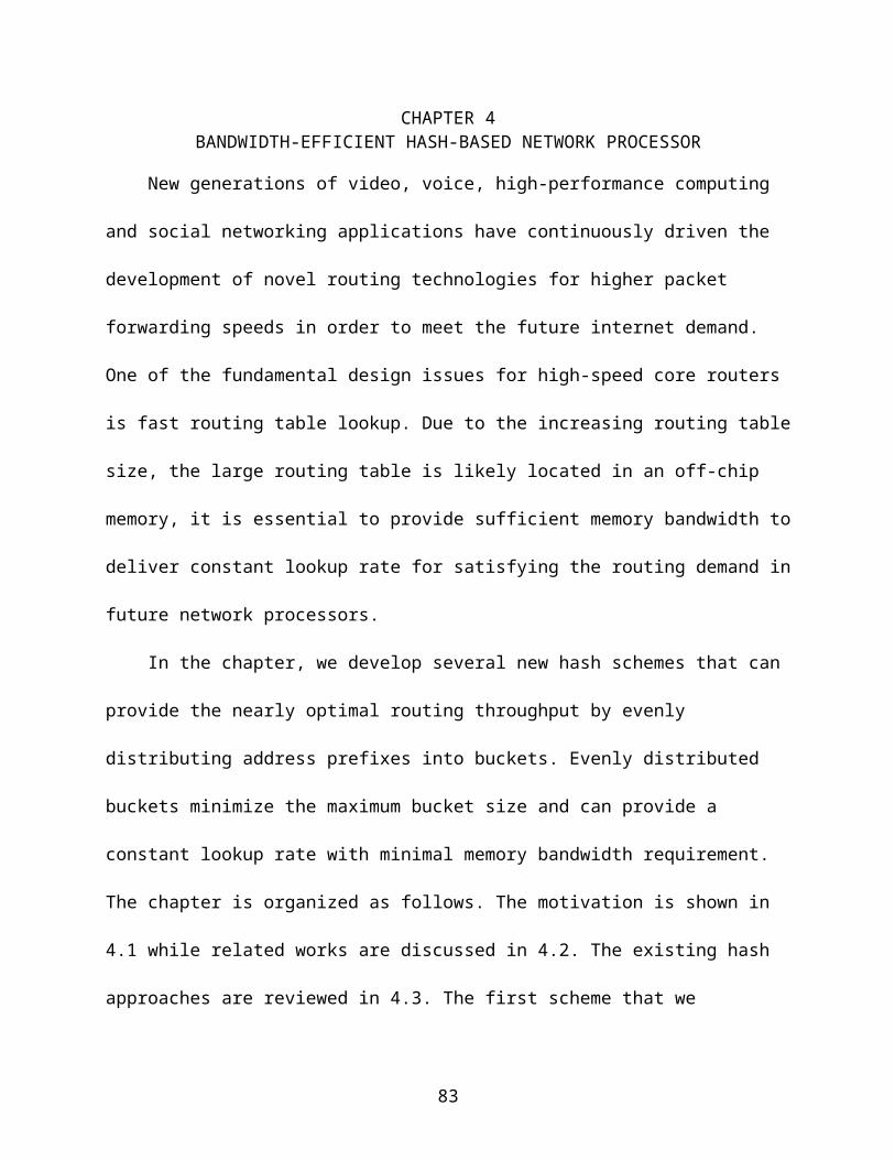
As shown in Figure 4-7, each prefix is first hashed to an entry in the index table
and the hash function index stored in the entry and the prefix is sent to the hash unit
where the d hash functions are implemented and the bucket in the hash table is finally
determined. Our SM-Hash function can be presented as:
h ( p )=hV (g ( p ))(p), where h0 ( p ) , h1 ( p ) ,…,hd−1 ( p ) are the d hash functions which hash
the prefix p to the buckets and g( p) is the hash function which hash the prefix p to the
index table and V (i) is the value stored in the i-th entry in the index table.
The index table has x entries and each entry contains l bits to code the d hash
functions, where l= log d. The SM-Hash can work with any x and d . In real design, we
limit the d to be power of 2 to make full use of the bits of an index table entry. Although
our SM-Hash can support tens or even hundreds hash functions without increasing the
off-chip memory access, we limit the number of hash functions to be 16 in our study
since the on-chip space is limited.
4.7.1 Setup Algorithm
In this section, we present how to setup the HIT to get the approximately perfect
bucket size. A complete search for the best HIT values needs to try all the xd
combinations and is unrealistic. Instead, we propose a two-step greedy setup approach,
first-setup and refine-setup.
4.7.1.1 First-setup
In the first-setup step, we setup the index table from empty. First, a general hash
function g( p) is selected. Then, the key set N is divided to x subgroupsG0 ,G1 ,…,Gx−1 ,
where Gi=p∨p∈N ,g ( p )=i. SM-Hash tries to allocate the buckets for all the keys in
subgroup Gitogether since all the them use the same hash function determined by the
83
value stored in the entry Ei. We search the suitable values for the index table in the
sequence V (0 ) ,V (1 ) ,…,V (x−1) and store the values in the index table as shown in
Figure 4-7.
When setting up one entry Ei in the index table, we try all the d possible hash
functions to hash the prefixes in the subgroup Gi. The d choices of the hash functions
give the d different ways to place the prefixes in the subgroup Gi and result in d different
bucket-load vectors as we used in the DM-Hash setup. We select the min-max of the d
vectors and use the corresponding hash function to place the prefixes and store the
hash function id in the index table entry Ei. The algorithm is summarized in Figure 4-8.
4.7.1.2 Refine-setup
However, the greedy setup approach in Figure 4-7 cannot guarantee the bucket
size is minimized. One reason is that only the keys in G0 ,…,Gi, are involved when
setting up the index table entryEi, but the keys in Gi+1 ,…,Gx−1 , are not considered.
The next step refine-setup can be used to further improve the load balance.
The refine-setup step improves the bucket size by retrying new values of each
entry in the index table. First, it retries all the d possible values for E0 and moves the
keys in G0 to the new buckets based on their new hash values. If any new value results
in more balanced buckets than the current one, E0 is updated to the new value. This
procedure repeats for E1 , E2 ,…, Ex−1.The Refine-Setup procedure can be executed
multiple times but usually once is enough.
4.7.2 Handling the Prefix updates
As we discussed in Section 4.6, the routing table updates needs to be carefully
handled since the routing tables are frequently changed. In the SM-Hash approach,
84
when a new prefix is inserted, the bucket the new prefix should be inserted to can be
calculated based on the existing values in the index table. However, it may cause a
bucket overflow as we see in the DM-Hash. In order to handle the overflow, we first use
the similar approach as for the DM-Hash and then we show a better approach.
4.7.2.1 Basic approach
Similar as we did in section 4.6, we add the index mapping table to the SM-Hash
to handle updates. It records the key subgroup G0 ,G1 ,…,Gx−1 and only is accessed
when a prefix is inserted or deleted. The new design is shown in Figure 4-9.
The new procedure to add a new prefix p can be presented as follows. First, we
calculate g( p) and h( p). If the bucket indexed by h( p) still has room to hold the new
prefix, the new prefix is added to the bucket and the whole procedure finishes.
Otherwise, we try to modify the index table entry Eiwhere i=g(x ). The subgroup Gi is
fetched from the index mapping table. We try a new value for Ei and check whether the
new prefix p and all the keys in Gi can find a room in the new buckets indexed by their
new hash values. If yes, we save the new value to Ei, move all the prefixes in Gi to the
new buckets and add p into its buckets. If all the possible values of Ei are failed, we
have to re-setup the whole SM-Hash table or use the TCAM. The procedure to add a
prefix in SM-Hash is summarized in Figure 4-10.
4.7.2.2 Enhanced approach
Although AP-Hash can handle the significant number of updates, it still may go to
a situation that it has to be re-setup or use the TCAM. Both re-setup and the TCAM is
expansive for the real network processor. In this section, we propose an enhanced
approach to further solve the bucket overflows.
85

Our basic approach already tries all the possible values of the index table entry
which the new prefix is hashed to. It suggests that only changing one entry is not
sufficient. Hence we need to find a way to modify other entries when adding a new
prefix to avoid the costly re-setup. And this direction leads us to the next approach, SM-
Hash-E.
Our SM-Hash-E works as follows: Instead to re-setup all the entries of the index
table, we can only adjust a few entries and move the keys which are associated with
those buckets to new buckets and see whether the overflow is solved. The majority of
the entries remain same and most of the prefixes are untouched. If we can make it
possible, we can avoid the costly re-setup. Now the problem is how many entries we
need to modify and how to select those entries.
When some bucket overflows, we can either move out the prefix which is just
added to it or move out some other prefix which is already in the bucket before the
insertion. If the basic approach fails, we can try the second choice, moving one prefix
that already placed in the bucket to a different bucket so that the new prefix can be
placed without overflow. In order to achieve this goal, we need to modify the index table
entry which the selected prefix is hashed to.
The SM-Hash-E for adding a new prefix is summarized in Figure 4-11. It is
executed after the previous SM-Hash algorithm (Figure 4-10) is failed. Although the SM-
Hash-E algorithm is complicated and needs to fetch several buckets from the main hash
table and entries in the index mapping table, it only is executed when the SM-Hash
addition algorithm is failed. So the average time for update remains similar compared to
the original SM-Hash addition algorithm.
86
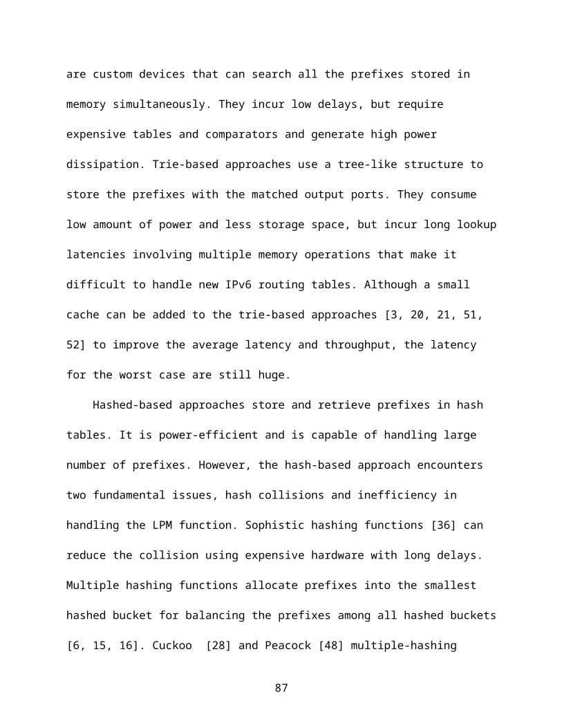
4.8 Two-Step Hashing (TS-Hash)
One problem about the SM-Hash is that it requires a few hash-functions to be
implemented on-chip. Each hash function consumes certain hardware recourse to
implement. Although we can reduce the number of hash functions, it affects the overall
SM-Hash balance. In this section, we modify the SM-Hash scheme to avoid using
multiple hash functions.
Recall the multiple hash functions are needed because we want to each prefix can
be placed into multiple locations. We need to find a different way to place the prefix into
multiple locations without invoking the multiple hash functions. In order to do that, we
allow the prefix to be moved around in the nearby buckets after a prefix is placed by
using one general hash function. We use the index table to record how each prefix is
moved from the original bucket. We call this mechanism as Two-Step Hash (TS-Hash)
since it takes two steps to find the bucket for each prefix, calculating the original bucket,
and adding the offset from the original bucket based on the index table.
As shown in Figure 4-12, TS-Hash also uses the small index table as DM-hash.
There are x entries in the index table and each entry in the index table contains an l-bit
integer in [0,2l−1]. The integers stored in the index table are the offsets from the original
bucket for each prefix. The hash value h( p) for each prefix is calculated as follows:
h ( p )=(h ' (p )⊕V (g ( p ) ) )modm, whereh ' ( p) is a general hash function which maps
the prefix to an integer between [0,m-1], g( p) is a different general hash function which
maps the prefix to an entry in the index table and V (i) the integer stored in the i-th entry
of the index table.
87
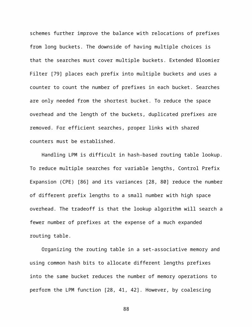
The setup algorithm in Figure 4-8 of SM-Hash can be similarly applied for the TS-
Hash. The routing table updates also can be handled in the similar way as TS-Hash.
Both the basic approach (section 4.7.2.1) and the enhanced approach (section 4.7.2.2)
can be applied for TS-Hash.
4.9 Experiment Results
4.9.1 Performance Evaluation Methodology
We use five routing tables from the Internet backbone routers: as286 (KPN
Internet Backbone), as6067 (Onyx Internet), as8468 (ENTANET International Ltd.),
as13030 (Init7 Global Backbone), and as29636 (Catalyst2 Services Ltd.), which are
downloaded from [72]. These tables are dumped from the routers at 11:59pm
December 31st, 2009. They are optimized to remove the redundant prefixes. The prefix
distributions of the routing tables are given in Table 4-3, where the first column is the
prefix length and other columns are the number of prefixes that have a given length.
We compare five hashing schemes in routing-table lookup with our longest prefix
match solution: single-hash, which uses one hash function to map the prefixes to the
buckets; NM-hash (d-left hash), which uses two hash functions; our DM-Hash, SM-
Hash, and TS-Hash. The reason we use only two hash functions for NM-Hash is that
more hash functions will significantly increase the computation and throughput
overhead but only marginally reduce the bucket size. The parameters for the index table
of DM-Hash, SM-Hash and TS-Hash are in Table 4-4.
In each experiment, we will select a routing table and a hashing scheme. We vary
the number of hash buckets m from 16K to 2M, each time doubling the value of m. We
find the prefixes in the routing table whose lengths are between 19 to 24, and expand
them to a certain length (22 or 23 in the experiments). For each value of m (16K, 32K,
88
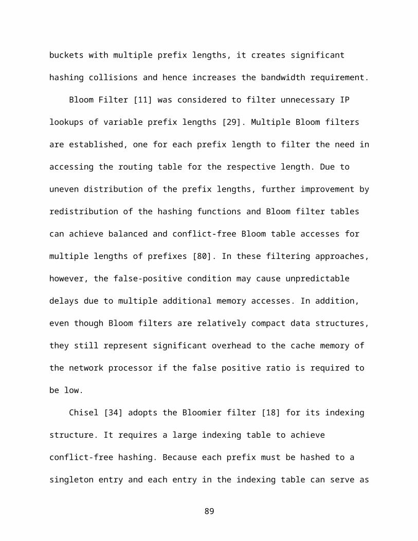
64K, 128K, 256K, 512K, 1M, or 2M), we distribute these prefixes to the buckets based
on the selected hashing scheme, and determine the bucket size Ω, which in turn
determines the bandwidth it takes to fetch a bucket to the network processor and
consequently determines the routing throughput. Eight different values of m will give us
eight data points.
4.9.2 Bucket Size and Routing Throughput
To calculate the routing throughput, we let each <prefix, output port> pair occupies
5 bytes (24 bits for the prefix and 16 bits for the output port). The current QDR-III
SRAMs runs at 500MHz and supports 72-bit read/write operations per cycle [67]. Let Ω
be the largest number of prefixes that a hashing scheme maps to a bucket. The routing
throughput (or lookup rate) can be computed as:
Throughput= 500
⌈ 40∗Ω72
⌉ (M/Sec)
Our evaluation results for the bucket size and the routing throughput are shown in
Figure 4-13, where the prefixes in the routing table are expanded to 22 bits. The
horizontal axis is the number of the buckets (m), and the vertical axis is the bucket size
(top) and the number of lookups per second (bottom). Each hashing scheme has eight
data points, which are the average among five routing tables.
As predicted, the single-hash scheme has the largest bucket size and low
throughput. Surprisingly, the NM-hash scheme has the lowest throughput. The reason is
that, although the NM-hash scheme has a smaller bucket size, it has to fetch two
instead of one bucket, which essentially gives up much of the throughput gain due to
smaller buckets. The throughput of the DM-hash scheme is much larger because not
89
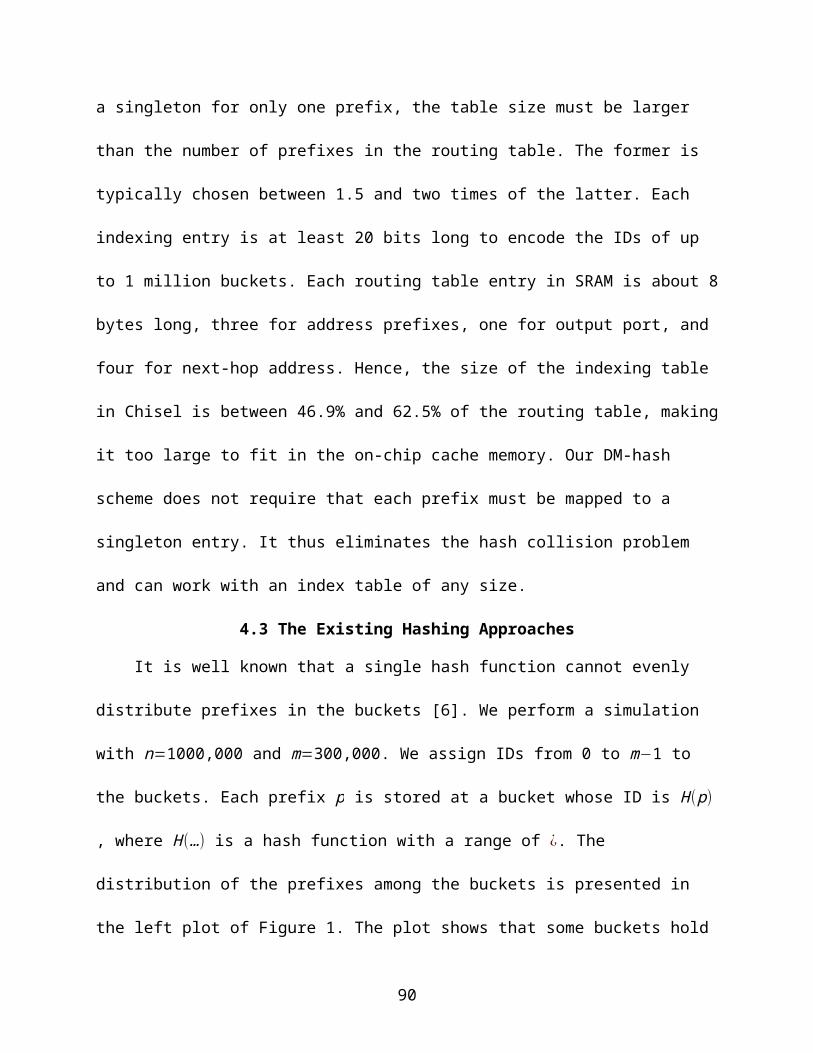
only does it reduce the bucket size, but also it fetches only one bucket. The throughputs
of SM-Hash and TS-Hash are very close to DM-Hash since all the three schemes can
achieve nearly optimal bucket size and only one bucket needs to be fetched for all of
them. Figure 4-14 shows similar results under expansion to 23.
The advocates of the NM-hash scheme argue that the buckets can be stored in
different memory banks and therefore the operation of fetching multiple buckets can be
performed in parallel in one off-chip access time. However, the parallelism will also help
the single-hash or DM-hash scheme, which can potentially process the lookups of
multiple packets in one off-chip access time. Moreover, it is costly to implement
parallelism in off-chip memory access.
4.9.3 Impact of Index Table Size
First, we study the performance of DM-hash under different index-table sizes
(ranging from 2K to 16K) in Figure 4-15. The sizes of the index tables are summarized
in Table 4-5, assuming that each entry in the index table occupies 24 bits, which
supports a maximum number of 224 buckets. As predicted, a larger index table helps to
balance the load in the hash buckets better, which means a smaller bucket size. A
smaller bucket size helps improve the routing throughput. The same conclusions can be
draw for SM-Hash (Figure 4-16) and TS-Hash (Figure 4-17).
4.9.4 Handle Routing Table Updates
In this section, we show how our new hash schemes can handle the routing table
updates. We use the same five selected routing table as the earlier experiments
dumped from the routers at 11:59pm December 31st, 2009. We setup the DM-Hash first
and then use the update traces from 12:00am January 1st, 2010 to 11:59pm January
31st, 2010 to test how our DM-Hash handles the updates to perform all the update
90

operations. The update traces downloaded from [72]. The details of the updates to the
five selected routing tables are summarized in Table 4-6.
We use the on-chip TCAM and off-chip SRAM hybrid structure as discussed in
Section 4.5. So whenever we insert/ delete/ modify a prefix, we need to insert/ delete/
modify to either the TCAM or the SRAM. The partial prefix expansion transforms the
insertion/ deletion/ modification of a short prefix to a set of insertions/ deletions/
modifications of longer prefixes. Hence, the number of updates to SRAM will be
increased. Table 4-5 shows the distribution of the routing table updates. We can see
most of the updates are handled by the SRAM.
4.9.4.1 Handle routing table updates with DM-Hash
As discussed before, the deletion and modification of an existing prefix are easy to
handle but the inserting a new prefix may cause the bucket overflow. In the experiment,
we first try to solve the overflow by modifying the index table and if it fails, we place the
new prefix into the on-TCAM for overflowed prefix.
We studied the routing table updates for the following parameters expanded to 23
bits, 512K buckets, 16K-entry index table and the bucket size limited to 3 (routing
throughput = 250 million packets per second). The results for prefix insertion are shown
in Table 4-7.
There are several conclusions that we can make from Table 4-7. First, most of the
prefix insertions do not cause the bucket overflow. Second, by modifying the index
table, 40% of the overflow can be resolved. The rest 60% need to be stored in the
TCAM. Third, the size of the TCAM to hold the overflowed prefixes is quite small, except
for as 286. Four, as286 has much more insertions and deletions than the other four
91

routing tables and results in higher chance to overflow and needs larger TCAM to hold
the prefixes.
The chance of bucket overflow can be greatly reduced by increasing the number
of the buckets. Hence, if the user finds the bucket overflow is too high or the needed
TCAM space is too large, the user can increase the number of the buckets. However,
even if we double the number of the buckets, it still will be few overflows which require
the modification of the index table.
4.9.4.2 Handle routing table updates with SM-Hash
We use the update traces for the first 100,000 insertions to test the SM-Hash
approaches and the results are summarized in Table 4-8. The basic approach
presented in section 4.7.2.1 solves the most of the bucket overflows caused by the
insertion. The rest few overflows can be covered with the enhanced approach. The
results show that the basic approach and enhance approach can cover the majority of
the routing table updates and avoid the re-setup.
4.10 Summary
The third work studies the problem of fast routing-table lookup. Our focus is on the
problem of minimizing both the size of each hash bucket and the number of buckets that
need to be fetched to the processor for packet forwarding. We introduce three new hash
schemes DM-Hash, SM-Hash and TS-Hash, which rely on a small intermediate index
table to balance the load on the buckets and also allow us to determine exactly which
bucket each prefix is stored. The result is a near-optimal throughput of over 250M table
lookups per second with today's commodity SRAM.
92

Although our study is centered on routing-table lookups, the proposed schemes
are very general and can be applied in other applications involving information storage
and retrieval. Applications such as page-table lookups in operating systems, intrusion
detections based on virus signature searches, key words matching in Google search
engines are possible candidates that can benefit from using the schemes developed in
this dissertation.
Figure 4-1. Up plot: the distribution of 1,000,000 prefixes in 300,000 buckets when a single hash function is used. Bottom plot: the distribution of n prefixes in m buckets when multiple hash functions are used. The distribution is more even if most buckets have similar number of prefixes around the average (which is 3.33). In this example, even distribution means that most buckets should have 3 or 4 prefixes and the minimum value of Ω is 4.
Table 4-1 Comparison of Single Hash, Multiple Hash (d-left Hash), DM-Hash, SM-Hash, TS-Hash
Bucket size (b) Bits fetched pre lookup
On-chip space (bits)
Off-chip space (bits)
93
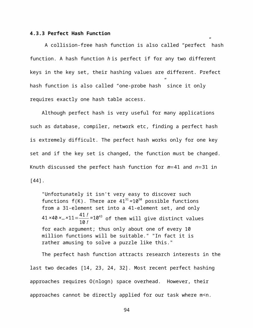
Single Hash Θ( lnm
ln ⌈1+mnln n ⌉
+ nm
) b×s 0 b×m×s
Multiple Hash (1+∘ (1 ) )× ln lnmlnd
+Ω( nm
) b×s×d 0 b×m×s
Perfect Hash
nm
b×s >2n b×m×s
DM-Hash nm
b×s x× logm b×m×s
SM-Hash nm
b×s x× log k b×m×s
TS-Hash nm
b×s x× l b×m×s
Figure 4-2. The design for NM-hash and DM-hash
Table 4-2. Notations used in DM-hashSymbol Meaning
x Number of entries in the index tableei An entry in the index tableGi A group of prefixesNi Hash neighborhood of Gi
Ei Given a progressive order of the entries, e1, e2, …, ex, we define E1 =e1, e2, …, ei
94

Figure 4-3. The distribution of 1,000,000 prefixes in 300,000 buckets under DM-hash with k = 3.
95

Figure 4-4 Longest prefix matching scheme with DM-Hash
Table 4-3. Prefix Distribution
Length as286 as6067 as8468as13030
as29636
8 16 17 16 16 179 10 10 10 10 10
10 21 21 21 21 2111 49 49 49 49 4912 140 140 140 140 14013 327 327 327 327 32714 540 540 539 537 54015 1065 1062 1062 1059 106516 9731 9692 9705 9712 970217 4513 4536 4505 4491 450618 7538 7515 7514 7506 752419 16491 16692 16644 16636 1663120 20324 20495 20484 20460 2047921 20294 20437 20427 20376 2037722 26698 26751 26716 26663 2671423 26474 26536 26529 26475 2649424 159444 159813 159395 159173 15937625 9 2 11 0 026 11 5 3 0 027 11 9 8 0 028 8 36 64 0 029 11 78 47 0 030 47 504 156 0 031 0 0 0 0 032 17 769 115 0 0
sum 293789 296036 294487 293651 293972
96

Figure 4-5. Number of prefixes after expansion
Figure 4-6. DM-Hash with Index Mapping Table
Figure 4-7. SM-Hash Diagram
97

Figure 4-8. SM-Hash Setup Algorithm
Figure 4-9. SM-Hash Diagram (With Index Mapping Table)
98

Figure 4-10. SM-Hash Algorithm to add a prefix p
Figure 4-11. SM-Hash-E Algorithm to add a prefix p
99
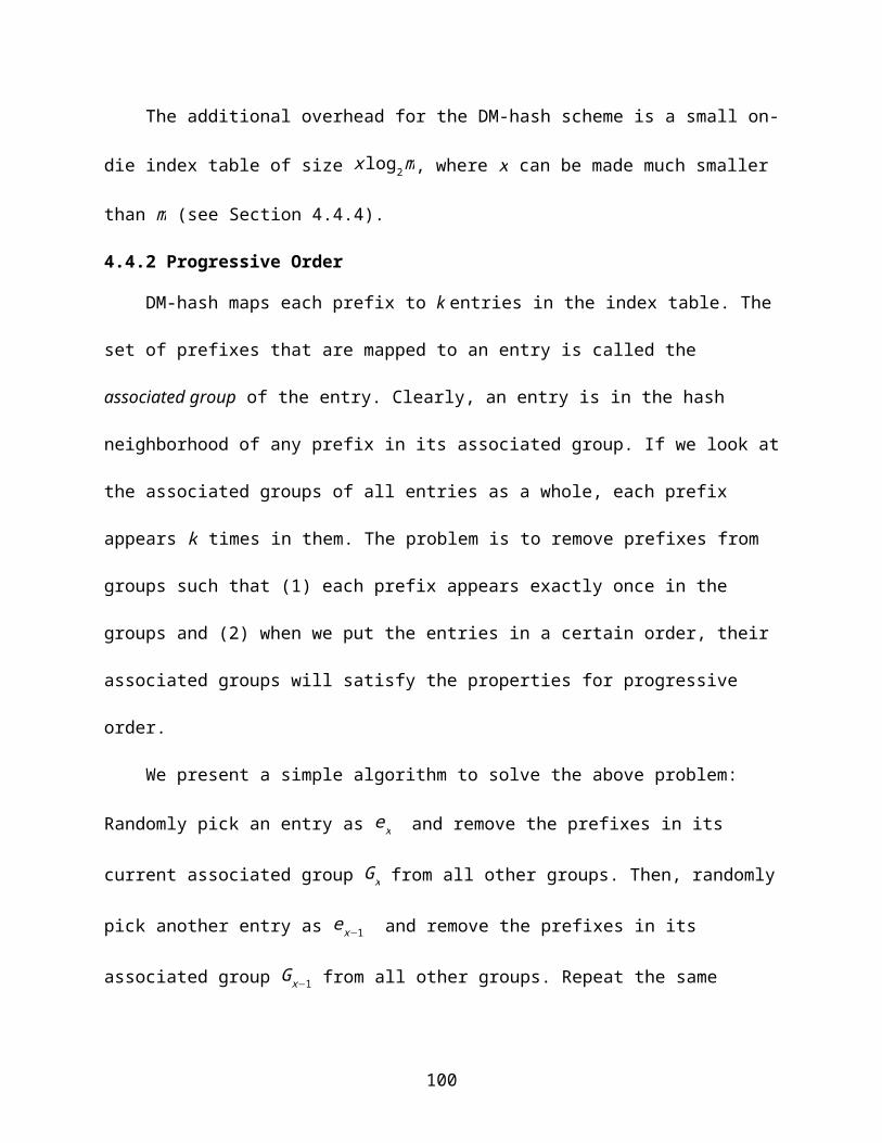
Figure 4-12. TS-Hash Diagram (With Index Mapping Table)
Table 4-4. Index Table for DM-Hash SM-Hash and TS-HashScheme Number of entries Bits per entry Size (KB)
DM-Hash 16K 24 48KBSM-Hash 64K 4 32KBTS-Hash 16K 8 16KB
100

Figure 4-13. Bucket size (top) and Routing throughput (bottom) comparison when the prefixes are expanded to 22 bits.
101

Figure 4-14. Bucket size (top) and routing throughput (bottom) comparison when the prefixes are expanded to 23 bits.
102
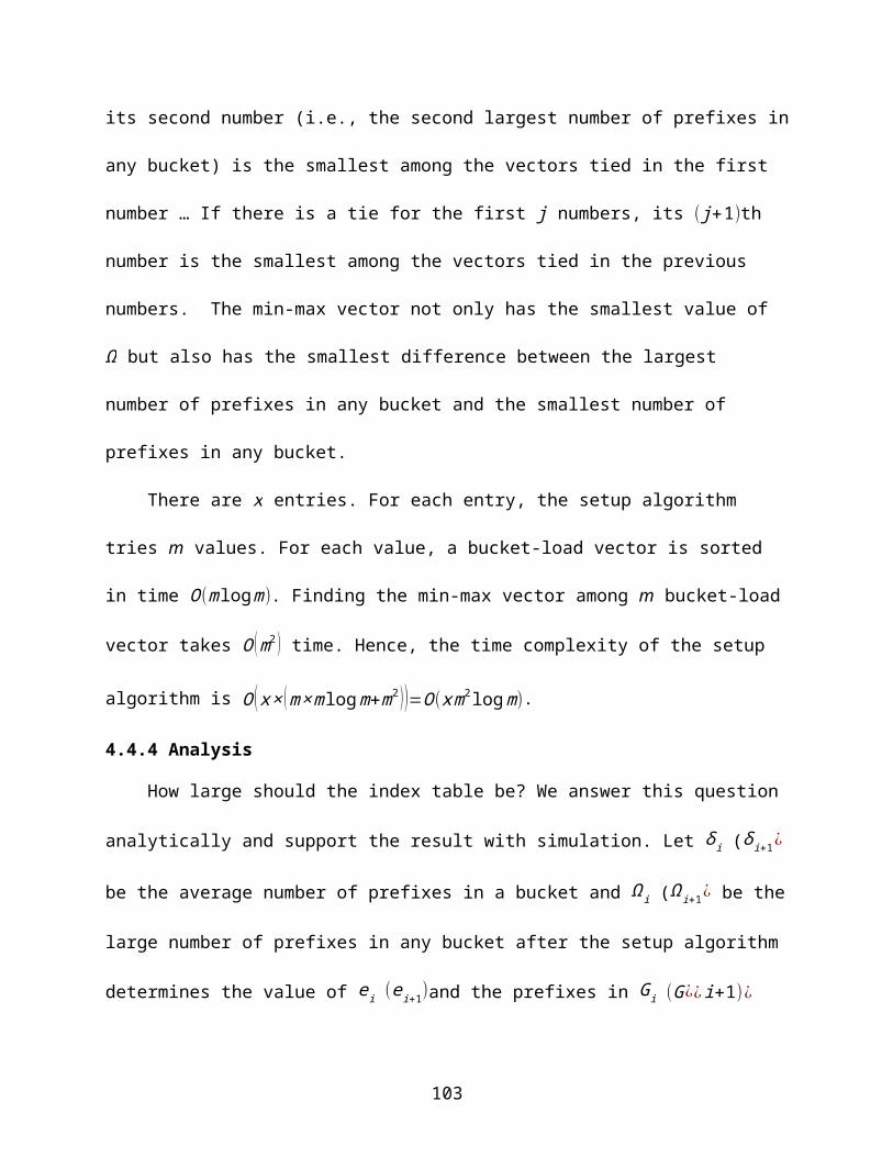
Figure 4-15. Bucket size under DM-hash with respect to index-table size.
Table 4-5. Index Table Size for DM-Hashx=2k X=4k X=8k x=16k
Number of entries 2048 4096 8192 16384Size (Kilo Bytes) 6KB 12KB 24KB 48KB
Figure 4-16. Bucket size under SM-hash with respect to index-table size.
103

Figure 4-17. Bucket size under TS-hash with respect to index-table size.
Table 4-6. Update Trace Summary
Table 4-7. Routing Table Updates with DM-Hash
Table 4-8. Routing Table Updates with SM-Hash
104
as286 as6067 as8468as13030
as29636
Insertion Original 2.54M 399K 611K 747K 1.18MTo SRAM 5.13M 659K 1.18M 1.31M 2.23MTo TCAM 170K 47K 33K 40K 67K
Deletion Original 2.53M 385K 599K 847K 1.22MTo SRAM 5.11M 654K 1.17M 1.40M 2.25MTo TCAM 167K 40K 30K 41K 67K
Modification
Original 12.86M 4.81M 7.19M 6.79M 8.59MTo SRAM 26.69M 10.24M 16.70M 14.22M 18.69MTo TCAM 882K 300K 551K 427K 513K
as286 as6067 as8468 as13030 as29636 averageSRAM insertion 5.13M 659K 1.18M 1.31M 2.23M 10.51MSRAM overflow per insertion 0.03 0.007 0.006 0.005 0.003 0.01Overflow solved by updating the index table per insertion 0.012 0.003 0.002 0.003 0.001 0.004Overflow solved by using the on-chip TCAM per insertion 0.017 0.004 0.004 0.002 0.002 0.006Overflow TCAM Size Needed 17251 848 1541 1061 923 4379
as286 as6067 as8468 as13030 as29636SRAM insertion 100000 100000 100000 100000 100000SRAM overflows 1468 4677 3650 2764 1998Solved by the basic approach 1461 4543 3581 2726 1978Solved by the enhanced approach 7 134 69 38 20Forced to re-setup 0 0 0 0 0

105
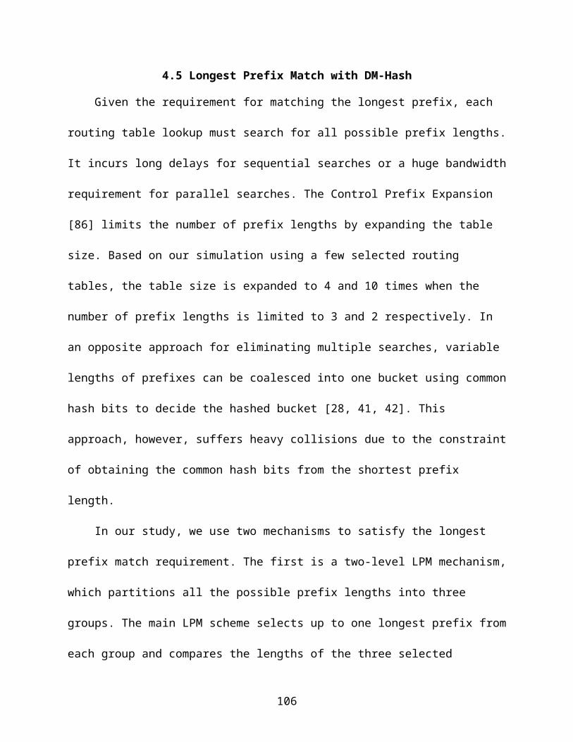
CHAPTER 5CONCLUSIONS
There is a growing performance gap between the processor and the main
memory. Memory hierarchy is introduced to bridge the gap for both general propose
processors and the specific processors such as network processors. One major issue
about the multiple-level memory system is that is needed to be efficiently managed so
that the hardware resource is well utilized. In this dissertation, we study three efficient
memory hierarchy designs.
The first work is a space-efficient design for CMP cache coherence directories,
named Alt-Home to alleviate the hot-home conflict. For any cached blocks, the
coherence information can be either stored at one of two possible homes, decided by
two hashing functions. We observe that the Alt-Home approach can reduce of 30-50%
of the L2 miss per instruction compared to the original single-home approaches when
the coherence directory space is limited.
As the second work of this dissertation, a greedy prefix caching mechanism is
proposed. It improves the previous MEP approach [3] by caching the parent prefixes.
An existing MEP is upgraded to its parent prefix to expand the cache coverage when
the leaf prefix is also cached. The new greedy cache can be applied to existing trie-
based algorithms without any modification to the prefix routing table. The experiment
results show the proposed prefix caching mechanism achieves up to 8% miss ratio
improvement compared with the existing prefix caches.
The third work focuses on the bandwidth efficient network processors. The hash-
based network processor needs to access the hash table to get the routing information.
The hash functions needs to be very balanced so that the memory bandwidth can be
106
fully utilized. We proposed two new hash functions based on a small on-chip memory
which is available in modern architectures. Both of our new approaches can achieve the
routing throughput over 250 millions packets per second. Our approaches can also be
widely applied to other applications involving information storage and retrieval.
107
LIST OF REFERENCES
[1] M. E. Acacio, et al., "A Two-Level Directory Architecture for Highly Scalable cc-NUMA Multiprocessors," IEEE Trans. Parallel Distrib. Syst., vol. 16, pp. 67-79, 2005.
[2] A. Agarwal, et al., "An evaluation of directory schemes for cache coherence," SIGARCH Comput. Archit. News, vol. 16, pp. 280-298, 1988.
[3] M. J. Akhbarizadeh and M. Nourani, "Efficient prefix cache for network processors," in Proceedings of the High Performance Interconnects, 2004. on Proceedings. 12th Annual IEEE Symposium, 2004, pp. 41-46.
[4] M. J. Akhbarizadeh, et al., "Pcam: A temary cam optimized for longest prefix matching tasks.," in Proceedings of 2004 international Conference on Computer Design: VLSI in Computers and Processors,, 2004, pp. 6-11.
[5] AS1221_BGP_Routing_Table_Analysis_Report. http://bgp.potaroo.net/as1221/.
[6] Y. Azar, et al., "Balanced Allocations," SIAM J. Comput., vol. 29, pp. 180-200, 2000.
[7] M. Azimi, et al., "Integration Challenges and Tradeoffs for Tera-scale Architectures," Intel Technology Journal, vol. 11, Aug. 2007.
[8] L. A. Barroso, et al., "Piranha: a scalable architecture based on single-chip multiprocessing," in Proceedings of the 27th annual international symposium on Computer architecture, Vancouver, British Columbia, Canada, 2000, pp. 282-293.
[9] B. M. Beckmann and D. A. Wood, "Managing Wire Delay in Large Chip-Multiprocessor Caches," in Proceedings of the 37th annual IEEE/ACM International Symposium on Microarchitecture, Portland, Oregon, 2004, pp. 319-330.
[10] B. Black, et al., "Die Stacking (3D) Microarchitecture," in Proceedings of the 39th Annual IEEE/ACM International Symposium on Microarchitecture, 2006, pp. 469-479.
[11] B. H. Bloom, "Space/time trade-offs in hash coding with allowable errors," Commun. ACM, vol. 13, pp. 422-426, 1970.
[12] F. Bodin and A. Seznec, "Skewed associativity improves program performance and enhances predictability," IEEE Trans. Softw. Eng., vol. 23, pp. 530-544, 1997.
108
[13] F. Bonomi, et al., "Beyond bloom filters: from approximate membership checks to approximate state machines," SIGCOMM Comput. Commun. Rev., vol. 36, pp. 315-326, 2006.
[14] F. C. Botelho, et al., "Simple and Space-Efficient Minimal Perfect Hash Functions," in WADS, 2007.
[15] A. Broder and A. R. Karlin, "Multilevel adaptive hashing," in Proceedings of the first annual ACM-SIAM symposium on Discrete algorithms, San Francisco, California, United States, 1990, pp. 43-53.
[16] A. Broder and M. Mitzenmacher, "Using multiple hash functions to improve IP lookups," in Proceedings of the 2001 IEEE INFOCOM 2001, pp. 1454-1463
[17] L. M. Censier and P. Feautrier, "A New Solution to Coherence Problems in Multicache Systems," IEEE Trans. Comput., vol. 27, pp. 1112-1118, 1978.
[18] B. Chazelle, et al., "The Bloomier filter: an efficient data structure for static support lookup tables," in Proceedings of the fifteenth annual ACM-SIAM symposium on Discrete algorithms, New Orleans, Louisiana, 2004, pp. 30-39.
[19] T.-c. Chiueh and P. Pradhan, "High-performance IP routing table lookup using CPU caching," in Proceedings of the 1999 IEEE INFOCOM, 1999, pp. 1421-1428.
[20] T.-c. Chiueh and P. Pradhan, "Cache Memory Design for Internet Processors," IEEE Micro, vol. 20, pp. 28-33, 2000.
[21] I. L. Chvets and M. H. MacGregor, "Multi-zone caches for accelerating IP routing table lookups," in 2002 Merging Optical and IP Technologies Workshop on High Performance Switching and Routing, 2002, pp. 121-126.
[22] D. Culler, et al., Parallel Computer Architecture: A Hardware/Software Approach: Morgan Kaufmann Publishers, Inc., 1999.
[23] Z. J. Czech, et al., "An optimal algorithm for generating minimal perfect hash functions," Inf. Process. Lett., vol. 43, pp. 257-264, 1992.
[24] Z. J. Czech, et al., "Perfect Hashing," Theoretical Computer Science, vol. 182, pp. 1-143, 1997.
[25] A. Czumaj and V. Stemann, "Randomized Allocation Processes," presented at the Proceedings of the 38th Annual Symposium on Foundations of Computer Science, 1997.
109
[26] Z. Dai and B. Liu, "A TCAM based routing lookup system," presented at the Proceedings of the 15th international conference on Computer communication, Mumbai, Maharashtra, India, 2002.
[27] M. Degermark, et al., "Small forwarding tables for fast routing lookups," SIGCOMM Comput. Commun. Rev., vol. 27, pp. 3-14, 1997.
[28] S. Demetriades, et al., "An Efficient Hardware-Based Multi-hash Scheme for High Speed IP Lookup," in Proceedings of the 2008 16th IEEE Symposium on High Performance Interconnects, 2008, pp. 103-110.
[29] S. Dharmapurikar, et al., "Longest prefix matching using bloom filters," in Proceedings of the 2003 conference on Applications, technologies, architectures, and protocols for computer communications, Karlsruhe, Germany, 2003, pp. 201-212.
[30] W. Eatherton, et al., "Tree bitmap: hardware/software IP lookups with incremental updates," SIGCOMM Comput. Commun. Rev., vol. 34, pp. 97-122, 2004.
[31] D. C. Feldmeier, "Improving gateway performance with a routing-table cache," in Proceedings of the 1988 IEEE INFOCOM, 1988, pp. 298-307.
[32] E. A. Fox, et al., "Practical minimal perfect hash functions for large databases," Commun. ACM, vol. 35, pp. 105-121, 1992.
[33] A. Gupta, et al., "Reducing Memory and Traffic Requirements for Scalable Directory-Based Cache Coherence Schemes," in Proceedings of International Conference on Parallel Processing, 1990, pp. 312--321.
[34] J. Hasan, et al., "Chisel: A Storage-efficient, Collision-free Hash-based Network Processing Architecture," in Proceedings of the 33rd annual international symposium on Computer Architecture, 2006, pp. 203-215.
[35] J. Hasan and T. N. Vijaykumar, "Dynamic pipelining: making IP-lookup truly scalable," SIGCOMM Comput. Commun. Rev., vol. 35, pp. 205-216, 2005.
[36] HDL Design House, "HCR MD5: MD5 crypto core family," Dec 2002.
[37] Intel Core Duo Processor, "The Next Leap in Microprocessor Architecture," Technology@Intel Magazine, Feb. 2006.
[38] I. Ioannidis, "Algorithms and data structures for IP lookups," Ph.D thesis, Purdue University, 2005.
110
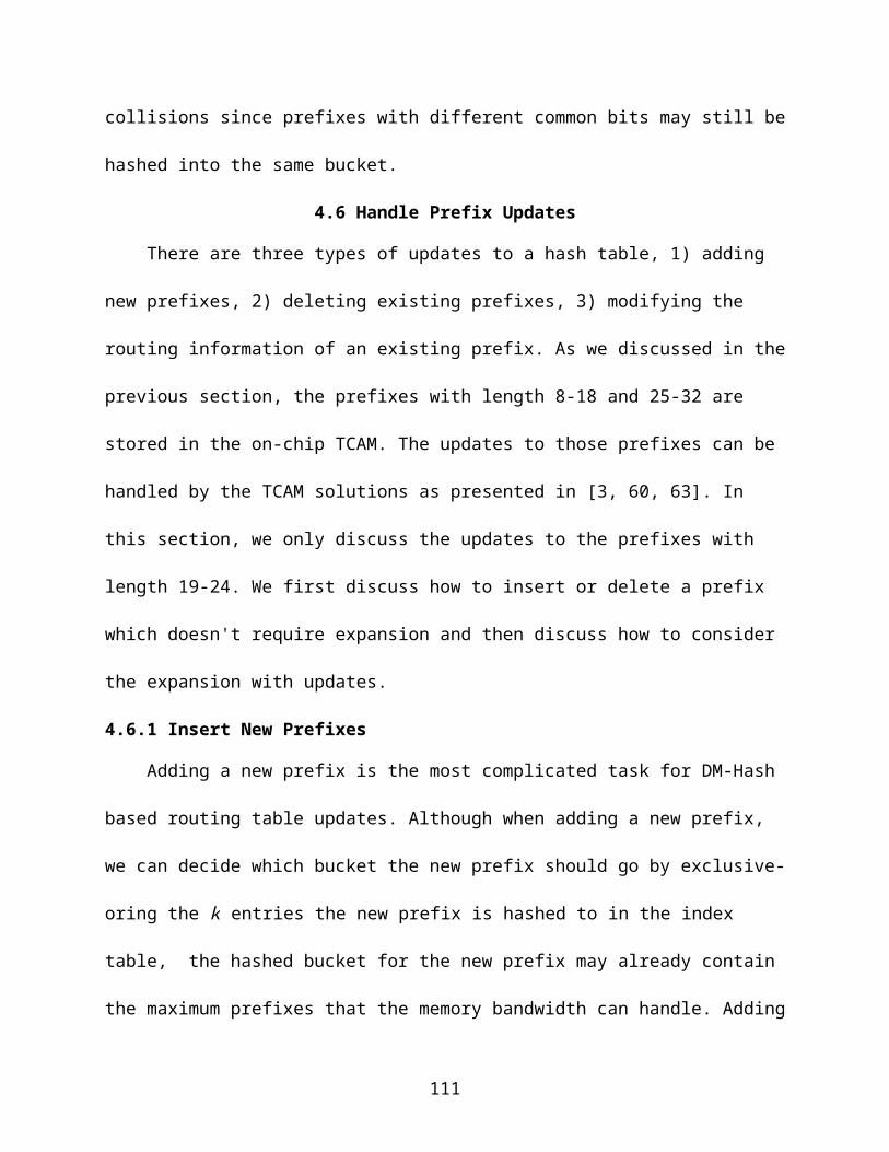
[39] W. Jiang, et al., "Beyond TCAMS: An SRAM-based Parallel Multi-Pipeline Architecture for Terabit IP Lookup," in Proceedings of the 2008 IEEE INFOCOM, 2008.
[40] S. Kapil, "UltraSPARC Gemini: Dual CPU Processor," presented at the Hot Chips 15, 2003.
[41] S. Kaxiras and G. Keramidas, "IPStash: a Power-Efficient Memory Architecture for IP-lookup," in Proceedings of the 36th annual IEEE/ACM International Symposium on Microarchitecture, 2003, p. 361.
[42] S. Kaxiras and G. Keramidas, "IPStash: A Set-Associative Memory Approach for Efficient IP-lookup," in Proceedings of the IEEE 2005 INFOCOM 2005.
[43] K. S. Kim and S. Sahni, "Efficient Construction of Pipelined Multibit-Trie Router-Tables," IEEE Transactions on Computers, vol. 56, pp. 32-43, 2007.
[44] D. E. Knuth, The art of Computer Programming, Volumn 3, Sorting and Searching vol. 3: Addison-Wesley Publishing Company, 1973.
[45] A. Kumar, et al., "Efficient and scalable cache coherence schemes for shared memory hypercube multiprocessors," in Proceedings of the 1994 ACM/IEEE conference on Supercomputing, Washington, D.C., 1994, pp. 498-507.
[46] A. Kumar, et al., "Express virtual channels: towards the ideal interconnection fabric," SIGARCH Comput. Archit. News, vol. 35, pp. 150-161, 2007.
[47] S. Kumar, et al., "CAMP: fast and efficient IP lookup architecture," presented at the Proceedings of the 2006 ACM/IEEE symposium on Architecture for networking and communications systems, San Jose, California, USA, 2006.
[48] S. Kumar, et al., "Peacock Hash: Fast and Updatable Hashing for High Performance Packet Processing Algorithms," in Proceedings of the 2008 IEEE INFOCOM, 2008.
[49] F. Li, et al., "Design and Management of 3D Chip Multiprocessors Using Network-in-Memory," SIGARCH Comput. Archit. News, vol. 34, pp. 130-141, 2006.
[50] D. J. Lilja and S. Ambalavanan, "A Superassociative Tagged Cache Coherence Directory," in Proceedings of the1994 IEEE International Conference on Computer Design: VLSI in Computer \& Processors, 1994, pp. 42-45.
[51] H. Liu, "Routing Prefix Caching in Network Processor Design," in Proceedings of the 10th International Conference on Computer Communications and Networks, 2001, pp. 18-23.
111
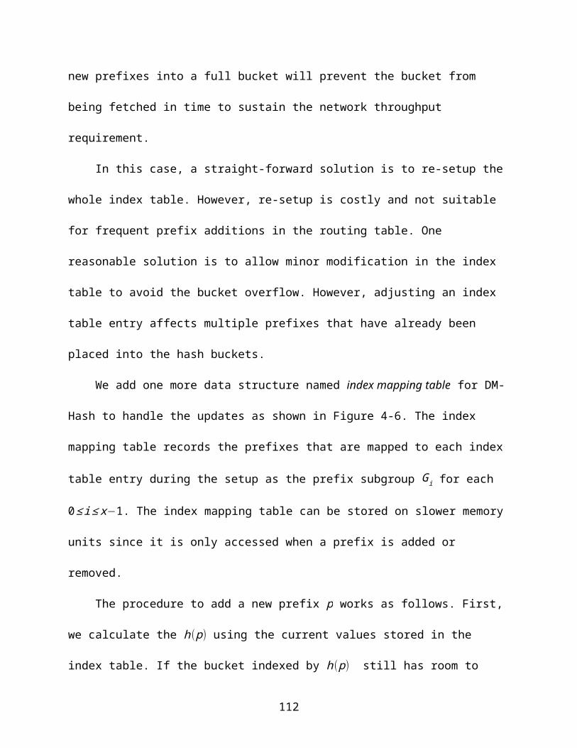
[52] H. Liu, "Reducing cache miss ratio for routing prefix cache," in Proceedings of the 2002 IEEE Global Telecommunications Conference, 2002, pp. 2323- 2327.
[53] H. Liu, "Routing Table Compaction in Ternary CAM," IEEE Micro, vol. 22, pp. 58-64, 2002.
[54] W. Lu and S. Sahni, "Packet Forwarding Using Pipelined Multibit Tries," in Proceedings of the 11th IEEE Symposium on Computers and Communications, 2006, pp. 802-807.
[55] P. S. Magnusson, et al., "Simics: A Full System Simulation Platform," Computer, vol. 35, pp. 50-58, 2002.
[56] M. R. Marty and M. D. Hill, "Virtual hierarchies to support server consolidation," in Proceedings of the 34th annual international symposium on Computer architecture, San Diego, California, USA, 2007, pp. 46-56.
[57] T. Maruyama, "SPARC64 VI: Fujitsu's Next Generation Processor," presented at the Microprocessor Forum 2003, 2003.
[58] MAWI Working_Group Traffic Archive. http://tracer.csl.sony.co.jp/mawi.
[59] A. J. Mcauley and P. Francis, "Fast Routing Table Lookup Using CAMs," in Proceedings of IEEE INFOCOM'93, 1993, pp. 1382--1391.
[60] M. Mitzenmacher, "The Power of Two Choices in Randomized Load Balancing," IEEE Trans. Parallel Distrib. Syst., vol. 12, pp. 1094-1104, 2001.
[61] H. Miyatake, et al., "A design for high-speed low-power cmos fully parallel content-addressable memory macros," IEEE JOURNAL OF SOLID-STATE CIRCUITS,, vol. 36, pp. 856-968, 2001.
[62] Multi-Core_Processors_from_AMD. http://multicore.amd.com/.
[63] X. Nie, et al., "IP Address Lookup Using a Dynamic Hash Function,," in Proceedings of the Canadian Conference on Electrical and Computer Engineering, 2005, 2005, pp. 1642-1647.
[64] Nvidia Fermi whitepaper, "http://www.nvidia.com/content/PDF/fermi_white_papers/NVIDIA_Fermi_Compute_Architecture_Whitepaper.pdf," 2010.
112

[65] B. W. O'Krafka and A. R. Newton, "An empirical evaluation of two memory-efficient directory methods," SIGARCH Comput. Archit. News, vol. 18, pp. 138-147, 1990.
[66] K. Olukotun, et al., "The case for a single-chip multiprocessor," SIGPLAN Not., vol. 31, pp. 2-11, 1996.
[67] M. Pearson. QDRTM–III: Next Generation SRAM for Networking. http://www.qdrconsortium.org/presentation/QDR-III-SRAM.pdf.
[68] M. K. Qureshi, et al., "Adaptive insertion policies for high performance caching," in Proceedings of the 34th annual international symposium on Computer architecture, San Diego, California, USA, 2007, pp. 381-391.
[69] M. K. Qureshi, et al., "The V-Way Cache: Demand Based Associativity via Global Replacement," SIGARCH Comput. Archit. News, vol. 33, pp. 544-555, 2005.
[70] M. V. Ramakrishna, et al., "Efficient Hardware Hashing Functions for High Performance Computers," IEEE Trans. Comput., vol. 46, pp. 1378-1381, 1997.
[71] V. C. Ravikumar, et al., "EaseCAM: An Energy and Storage Efficient TCAM-Based Router Architecture for IP Lookup," IEEE Transactions on Computers, vol. 54, pp. 521-533, 2005.
[72] Routing_Information_Service. http://www.ripe.net/ris. [73] M. Á. Ruiz-Sánchez, et al., "Survey and taxonomy of IP address lookup
algorithms," IEEE Network, vol. 15, pp. 8-23, 2001.
[74] S. Sahni and K. S. Kim, "Efficient construction of multibit tries for IP lookup," IEEE/ACM Trans. Netw., vol. 11, pp. 650-662, 2003.
[75] A. Seznec, "A case for two-way skewed-associative caches," SIGARCH Comput. Archit. News, vol. 21, pp. 169-178, 1993.
[76] Single-chip_Cloud_Computer, "http://techresearch.intel.com/articles/Tera-Scale/1826.htm," 2009.
[77] B. Sinharoy, et al., "POWER5 System microarchitecture," IBM J. Res. Dev., vol. 49, pp. 505-521, 2005.
[78] A. J. Smith, "Cache Memories," ACM Comput. Surv., vol. 14, pp. 473-530, 1982.
[79] H. Song, et al., "Fast hash table lookup using extended bloom filter: an aid to network processing," SIGCOMM Comput. Commun. Rev., vol. 35, pp. 181-192, 2005.
113

[80] H. Song, et al., "IPv6 Lookups using Distributed and Load Balanced Bloom Filters for 100Gbps Core Router Line Cards," in Proceedings of IEEE INFOCOM 2009, 2009.
[81] H. Song, et al., "Shape Shifting Tries for Faster IP Route Lookup," presented at the Proceedings of the 13TH IEEE International Conference on Network Protocols, 2005.
[82] SPEC CPU2000, "http://www.spec.org/cpu2000/," 2007.
[83] SPEC CPU2006, "http://www.spec.org/cpu2006/," 2006.
[84] SPEC jbb2005, "http://www.spec.org/jbb2005/."
[85] M. Spjuth, et al., "Skewed caches from a low-power perspective," in Proceedings of the 2nd conference on Computing frontiers, Ischia, Italy, 2005, pp. 152-160.
[86] V. Srinivasan and G. Varghese, "Fast address lookups using controlled prefix expansion," ACM Trans. Comput. Syst., vol. 17, pp. 1-40, 1999.
[87] Sun Niagara2 Processor. http://www.sun.com/processors/niagara/.
[88] C. K. Tang, "Cache system design in the tightly coupled multiprocessor system," in Proceedings of the 1976 national computer conference and exposition, New York, New York, 1976, pp. 749-753.
[89] S. R. Vangal, et al., "An 80-Tile 1.28TFLOPS Network-on-Chip in 65nm CMOS," presented at the 2007 international Solid-State Circuits Conference, 2007.
[90] B. Vocking, "How asymmetry helps load balancing," J. ACM, vol. 50, pp. 568-589, 2003.
[91] F. Zane, et al., "CoolCAMs: Power-Efficient TCAMs for Forwarding Engines " in Proceedings of IEEE INFOCOM'03, 2003.
114
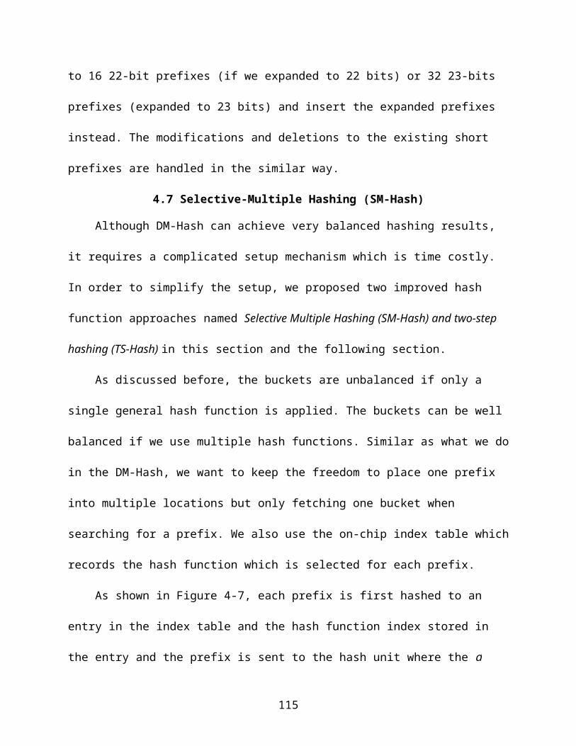
BIOGRAPHICAL SKETCH
Zhuo Huang was born in Suzhou, Jiangsu Province, China, in 1981. He received
his Bachelor of Engineering in computer engineering and Bachelor of Management from
the University of Science and Technology of China in 2002 and Master of Engineering
in computer engineering from Institute of Software, Chinese Academy of Sciences in
2004. In August 2004, he came to University of Florida to pursue his Ph.D. degree in
the Department of Computer and Information Science and Engineering under the
supervision of Dr. Jih-Kwon Peir. In December 2010, he received his Ph.D. degree.
115