university of groningen advanced molecular devices based
TRANSCRIPT

University of Groningen
Advanced molecular devices based on light-driven molecular motorsChen, Jiawen
IMPORTANT NOTE: You are advised to consult the publisher's version (publisher's PDF) if you wish to cite fromit. Please check the document version below.
Document VersionPublisher's PDF, also known as Version of record
Publication date:2015
Link to publication in University of Groningen/UMCG research database
Citation for published version (APA):Chen, J. (2015). Advanced molecular devices based on light-driven molecular motors. [S.n.].
CopyrightOther than for strictly personal use, it is not permitted to download or to forward/distribute the text or part of it without the consent of theauthor(s) and/or copyright holder(s), unless the work is under an open content license (like Creative Commons).
The publication may also be distributed here under the terms of Article 25fa of the Dutch Copyright Act, indicated by the “Taverne” license.More information can be found on the University of Groningen website: https://www.rug.nl/library/open-access/self-archiving-pure/taverne-amendment.
Take-down policyIf you believe that this document breaches copyright please contact us providing details, and we will remove access to the work immediatelyand investigate your claim.
Downloaded from the University of Groningen/UMCG research database (Pure): http://www.rug.nl/research/portal. For technical reasons thenumber of authors shown on this cover page is limited to 10 maximum.
Download date: 06-02-2022

Chapter 1: Controlling Motion at Molecular Level
Chapter 1
2
1.1 Introduction
Nature has provided a large collection of molecular machines and devices that
are among the most amazing nanostructures on this planet. These machines are
able to operate responsive and complex biological processes which are of great
importance in our organisms. 1 These processes are accomplished with high
efficiency and selectivity under precise control at molecular level. Analogous to
mechanical machines and their internal motor engines in the macroscopic world,
biological molecular motors 2 are essential to the functioning of molecular
machines in the cell. These molecular motors are capable of converting chemical
or thermal energy to generate the forces and motion required for the system to
control and perform a variety of biological functions. For example, ATP synthase
contains a genuine molecular rotary motor to control the process of synthesizing
or hydrolyzing ATP.3 Other examples include the flagella motor4 that helps the
movement of a bacterial, linear motors5 that are involved in muscle contraction
and intracellular transport and proteins that trap and release guests through
chemomechanical motion.
These fascinating biological systems have served as a major source of
inspiration for the rapidly developing field of nanotechnology. Directly employing
these complex biological motors outside the cell to perform useful tasks could be
the first idea in scientists’ mind. Despite a few examples,6 a major disadvantage
of the application of these biological motors ex vivo is their inherent instability
outside their natural environment and thus high restrictions for the conditions that
they operate in. Therefore, it is desirable to develop simpler systems that can
tolerate a more diverse range of conditions. This challenge has led to the design
and construction of artificial nanostructures that operate as molecular motors or
switches. In physics the focus is more on milling larger structures down to create
smaller structures, which is referred to as the “top-down” approach. An alternative
approach is to build up a completely synthetic system from small building blocks,
commonly termed as “bottom-up”.7 In the “bottom-up” approach, the advances of
synthetic chemistry could provide unlimited possibilities to construct systems that
do not only mimic but also go beyond the natural molecular machines.
In last decades, a variety of synthetic machinery based on molecular motors
and switches has been developed to demonstrate that people are able to harness
motion of molecules to achieve a certain function.8 However, current efforts to

Controlling Motion at Molecular Level
3
control motion at the molecular level still seem naive compared with the elegant
and sophisticated natural systems. This is because forces that govern the
movement of macroscopic object, such as gravity and friction, have little impact
on the motion at molecular level. The random and thermally driven motion,
known as Brownian motion, is the dominant factor at the molecular level.
Brownian motion causes all components to move, vibrate and rotate incessantly
and randomly at temperatures above 0 K. Therefore, a contemporary major
challenge in nanotechnology is that how to exploit or overcome Brownian motion9
to precisely control the motion of artificial molecular motors and switches.
Moreover, fine tuning of the motor speed, control over the directionality and fast
respond to external stimuli (light, heat, electricity) are also important issues.
In this chapter, some biological motors provided by Nature will be briefly
discussed. First the understanding how biological systems work provides
important guidelines for the design of artificial motor structures. Second,
examples of the application of biological motors in nanotechnology will be
addressed. The major part of this chapter will focus on the efforts to gain control
over molecular motion and examples will be discussed in which controlled motion
is used to control a variety of functions in a dynamic way.
1.2 Biological rotary motors
1.2.1 F0F1-ATP synthase
Motor protein can be found in mitochondria, bacteria and chloroplasts. It
consists of two subunits F0 and F1 which are linked by a central axis (Figure 1).
F0 is a proton pump embedded in a membrane whereas F1 sticks out of the
membrane. The transportation of proton through F0, driven by a proton gradient,
drives an unidirectional rotation of the central axle connecting F0 and F1. This
process induces conformational changes of F1, which enables the formation of
ATP. Notably, this process can be reversed by using the same mechanical
device to convert the energy from ATP hydrolysis into a rotary motion to produce
a proton gradient.10 The hydrolysis of 390 molecules of ATP per second can
provide a rotational rate of 130 revolutions per second. It is worthy to note that,
high efficiency can be achieved in the whole process where chemical energy is
converted into mechanical energy.11

Chapter 1
4
Figure 1. F0F1-ATP synthase.
1.2.2 Bacteria flagellar motors
Some bacteria, such as Escherichia coli, are equipped with long rotating
flagella. This flagella is located on the outside of outer cell membrane, which
allows the bacteria to ‘swim’ in solution to seek better living conditions. The
passive, rigid helical motion of the flagella is driven by a rotary motor. This rotary
motor is assembled from more than 20 proteins and embedded in the inner cell
membrane.12 A flux of either protons or sodium ions across the inner membrane
of the bacterium can serve as the driving force of the motors. The system is
surprisingly efficient; the rotary speed can reach over 100 Hz.13
Figure 2. Bacterial flagellar motor.
1.3 Harnessing biological motors
Linear motors are found in many proteins that can transport cargo to a precise
target location. Among these motors, myosin motors are guided by actin
filaments, while dynein and kinesin motors move along rod-like microtubules.14
The long-range guidance of cargo is made possible by motors pulling their cargo

Controlling Motion at Molecular Level
5
along the protein polymers that form the cytoskeleton which extends throughout
the cell. These polymeric rods are inherently unstable: they polymerize at one
end while depolymerizing from the other end, giving rise to structural polarity,
which allows unidirectional movement of motors along their tracks. In fact, linear
cytoskeletal kinesin and myosin motors have been used frequently in the field of
protein-powered devices for the simple reason that they are readily available.
Actin and tubulin can be commercially purchased and the motor can be purified
from cells or expressed in recombinant bacterial system and isolated in large
quantities. A recent example showed that a combination of topographical and
chemical patterning,15 with the motor proteins only at the bottom of the trenches
(Figure 3), can be an effective way in guiding and confinement of microtubules16
and actin17.
Figure 3. Actin filaments in the letter-shaped tracks. (Reproduced from ref. 17,
copyright 2005 IOP Science)
In addition to using isolated nanomotors, hybrid biodevices and systems that
harness self-propelling microbes could be used to drive transport processes
along engineered tracks. Flagellated bacteria, for example, have been reported to
generate both translational and rotational motion of microscopic objects.18 These
bacteria can be attached head-on to solid surfaces, either via polystyrene beads
or polydimethylsiloxane, which enables the cell bodies to form a densely packed
monolayer, while their flagella continue to rotate freely. In fact, a microrotary
motor, fuelled by glucose and comprising a cogwheel-shaped 20-μm-diameter
silicon dioxide rotor, can be driven along a silicon track by the gliding bacterium
Mycoplasma.19 Some biological motors can be produced at extremely low cost
and modified using modern biotechnological tools. However, as mentioned in
section 1.1, a major drawback of biomolecular motors is their limited lifetime ex
vivo and the narrow range of environmental conditions that they are able to

Chapter 1
6
tolerate. Therefore, artificial systems based on synthetic compounds might offer
considerable advantages for the development of nanotechnology.
1.4 Artificial molecular rotors and motors
Inspired by the variety of examples in Nature, researchers have spent a lot of
effort in past decades on designing and constructing artificial systems that are
able to mimic or partially mimic the natural biological systems. One key challenge
is to control the motion of molecules, out of the random thermal Brownian motion.
In this section, first the initial designs and attempts to build a synthetic system to
control molecular motion will be discussed. Subsequently, several examples are
mentioned of different molecular systems which achieve controlled molecular
motion. Finally, light-driven molecular motors based on overcrowded alkenes will
be discussed in detail.
1.4.1 Gyroscope-like molecular rotors
Gladysz and coworkers have developed a class of rotors which he refers to as
gyroscopes. These cage-like molecules that duplicate the connectivity and
symmetry of a toy gyroscope consist of a stator outside with a rotator on the
inside (Scheme 1). A general synthetic strategy for the synthesis of this family of
molecules based on ring-closing metathesis is described in Scheme 1. Accessed
from precursors with trans-phosphine ligands via alkene
metathesis/hydrogenation sequence, these molecules were obtained in good to
moderate yield.
Scheme 1. General synthetic strategy for molecular gyroscope.
The first rotor involved trigonal-bipyramidal iron tricarbonyl species 1a-1c
(Scheme 2).20 Only one methylene (PCH2) signal was observed in the 13C NMR
spectrum which means {Fe(CO)3} rotates fast on the NMR timescale. Replacing

Controlling Motion at Molecular Level
7
one carbonyl ligand with NO resulted in two sets of the P(CH2) signal in a ratio of
2:1 in the 13C NMR spectra of 2a,b+BF4-.20 However, the spectrum of 2c+.BF4
- still
gave only one signal, indicating that rotation of {Fe(CO)2(NO)}+ is fast on the
NMR timescale at room temperature for 2c+.BF4-, but slow for 2a,b+BF4
- that have
longer spokes. This provides a way to adjust the rotational barrier of the interior
rotator by changing the lengths of the stator.
Scheme 2. Gyroscope-like complexes 1-5.
Another way to adjust the rotary speed is to change the metal and ligand of the
rotator. When square-planar palladium or platinum is used, the 13C NMR spectra
of 3c,d and 4c,d showed two sets of methylene carbons (PCH2) even when the
temperature is heated to 80 oC, but only one set for 3a,b and 4a,b.21 It indicated
that with sufficiently large ligands, such as SCN or Ph, the rotation can be
retarded. The same method has been applied to giant gyroscope-like molecules
5a-c that incorporated rigid p-disubsitituted benzene rings.22 When X is Cl and
C6H5C≡C-, only a single set of signals for P(CH2) group can be observed on 13C
NMR even cooled to temperatures as low as -70 oC, which clearly demonstrated
the rapid rotation of the Cl-Rh-CO and C6H5C≡C-Rh-CO moieties about the P-
Rh-P axes in solution. But when chloride is changed to p-CH3C6H4C≡C-, a clear
2:1 ratio of P(CH2) persist in spectra even at 120 oC, thus indicating the motion is
blocked effectively.
The major disadvantage of the two ways mentioned above for modulating rotary
motion is that it consists of an irreversible chemical transformation. A better
design was proposed, based on coordinating the metal with CO groups. The
rhodium-based rotors can be reversibly switched between faster and slower
Chapter 1
8
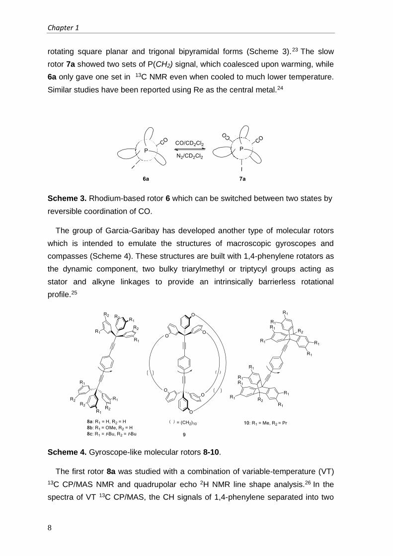
rotating square planar and trigonal bipyramidal forms (Scheme 3).23 The slow
rotor 7a showed two sets of P(CH2) signal, which coalesced upon warming, while
6a only gave one set in 13C NMR even when cooled to much lower temperature.
Similar studies have been reported using Re as the central metal.24
Scheme 3. Rhodium-based rotor 6 which can be switched between two states by
reversible coordination of CO.
The group of Garcia-Garibay has developed another type of molecular rotors
which is intended to emulate the structures of macroscopic gyroscopes and
compasses (Scheme 4). These structures are built with 1,4-phenylene rotators as
the dynamic component, two bulky triarylmethyl or triptycyl groups acting as
stator and alkyne linkages to provide an intrinsically barrierless rotational
profile.25
Scheme 4. Gyroscope-like molecular rotors 8-10.
The first rotor 8a was studied with a combination of variable-temperature (VT)
13C CP/MAS NMR and quadrupolar echo 2H NMR line shape analysis.26 In the
spectra of VT 13C CP/MAS, the CH signals of 1,4-phenylene separated into two
Controlling Motion at Molecular Level
9
sets when the temperature was below 250 K. From these data, it was possible to
calculate the activation energy which is 12.8 kcal/mol. The rotary speed is 800 Hz
at 298 K and reaches up to 1.3 × 10⁶ Hz at 338 K. But in the crystal lattice, due to
the steric interaction between the rotor and the adjacent molecules and the
incorporation of solvent molecules, the rotation is limited to certain degree. A way
to improve the speed is to introduce substitutions on stator, which increase the
distance to neighboring molecules, providing a lager local cavity that shields the
rotator. In 8b27,28 a methoxy group was applied and rotation speed was increased
to 5000 Hz (Ea ≈ 10.5 kcal/mol) and for 8c29 with a bulky tert-butyl group, this was
106 Hz ((Ea ≤ 5 kcal/mol). A fully encapsulated rotor 9 was also made, which
resembles Gladysz’s design. 30 Unfortunately in the crystal lattice, the
incorporation of solvent molecules partly hindered the rotation, which indicated
the spoke does not give a good protection. When the triarylmethyl groups on the
stator changed to triptycyl, the rotation of 10 can be as fast as 6.5 × 10⁶ Hz (Ea ≈
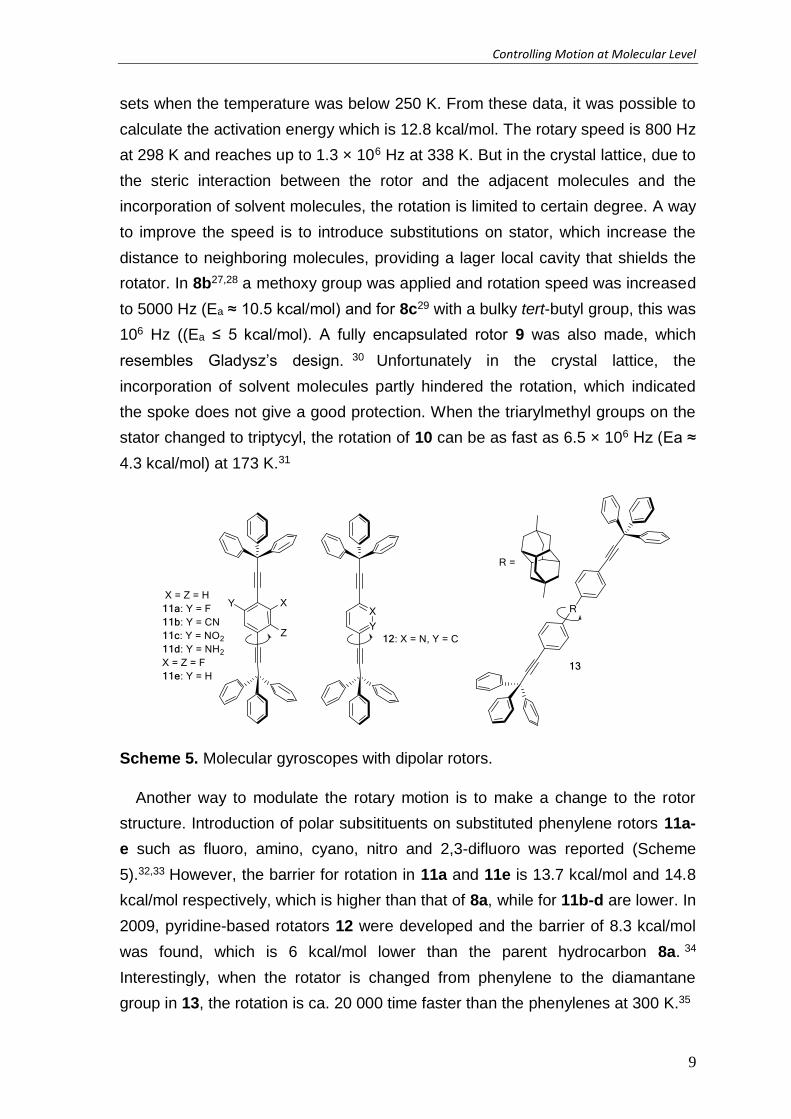
4.3 kcal/mol) at 173 K.31
Scheme 5. Molecular gyroscopes with dipolar rotors.
Another way to modulate the rotary motion is to make a change to the rotor
structure. Introduction of polar subsitituents on substituted phenylene rotors 11a-
e such as fluoro, amino, cyano, nitro and 2,3-difluoro was reported (Scheme
5).32,33 However, the barrier for rotation in 11a and 11e is 13.7 kcal/mol and 14.8
kcal/mol respectively, which is higher than that of 8a, while for 11b-d are lower. In
2009, pyridine-based rotators 12 were developed and the barrier of 8.3 kcal/mol
was found, which is 6 kcal/mol lower than the parent hydrocarbon 8a. 34
Interestingly, when the rotator is changed from phenylene to the diamantane
group in 13, the rotation is ca. 20 000 time faster than the phenylenes at 300 K.35
Chapter 1
10
Glydysz and Garcia-Garibay’s design are based on gyroscope or compasses in
macroscopic world. Both studies show that they are able to “halt” the rotary
motion or tune the speed of rotary motion by modifying the molecular structures.
Furthermore, Gladysz provided a simple method to reversibly switch between a
fast or slow rotor. These are important features that demonstrate how control
over rotary motion might be achieved. However, the direction of the motion in
these system is still random. Although some of rotors that feature dipole moment
were synthesized and crystallized,21,32 which provides possible opportunities to
drive the molecules to turn unidirectionally in rotating electric fields, no data
regarding such control of motion has been reported so far.
1.4.2 Molecular motors based on interlocked systems
Another design to control molecular motion is to organize molecules into
mechanically interlocked or topologically linked structure. The molecules are
linked together not through a covalently bond, but through their spatial
configuration or non-covalent mechanical interaction. If the system consists of (at
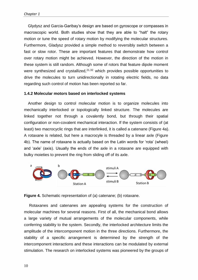
least) two macrocyclic rings that are interlinked, it is called a catenane (Figure 4a).
A rotaxane is related, but here a macrocyle is threaded by a linear axle (Figure
4b). The name of rotaxane is actually based on the Latin words for ‘rota’ (wheel)
and ‘axle’ (axis). Usually the ends of the axle in a rotaxane are equipped with
bulky moieties to prevent the ring from sliding off of its axle.
Figure 4. Schematic representation of (a) catenane; (b) rotaxane.
Rotaxanes and catenanes are appealing systems for the construction of
molecular machines for several reasons. First of all, the mechanical bond allows
a large variety of mutual arrangements of the molecular components, while
conferring stability to the system. Secondly, the interlocked architecture limits the
amplitude of the intercomponent motion in the three directions. Furthermore, the
stability of a specific arrangement is determined by the strength of the
intercomponent interactions and these interactions can be modulated by external
stimulation. The research on interlocked systems was pioneered by the groups of
Controlling Motion at Molecular Level
11
Sauvage36 and Stoddart37. Over the past decades, various efficient synthetic
methods to optimize the yield of these complex structures have led to more
sophisticated systems. 38 In this section, some characteristic examples are
mentioned to demonstrate how controlled molecular motion is achieved and more
importantly, the incorporation of these controlled motion into unique functions.
The most important feature of these interlocked systems is that different
‘stations’ can be introduced on the thread-component of a rotaxane or catenene.
The macrocyclic component, in principle, can shuttle between these ‘stations’
involving non-covalent interactions between ring and thread component that
contain complementary recognition sites. The interactions include hydrogen
bonding, hydrophilic-hydrophobic interaction, electrostatic interaction, metal-
ligand interaction, - stacking, etc. The shuttle between these ‘stations’ could be
controllable if these interactions are responsive to external chemical,
electrochemical or photochemical stimuli. For example, as shown in Figure 4b,
the macrocycle (red) resides preferentially around station A (blue). A stimuli A is
applied that switches off this recognition site (A→A’, blue → gray). The rotaxane
then equilibrates according to the new potential energy landscape, and the
macrocycle moves by Brownian motion to the second recognition site station B. If
station A is switched on again (A'→A, gray to blue) by an opposite stimuli B, the
original potential energy landscape is restored, and another conformational
equilibration occurs through the shuttling of the macrocycle from station B to
station A by Brownian motion. With specific external stimuli, the macrocycle
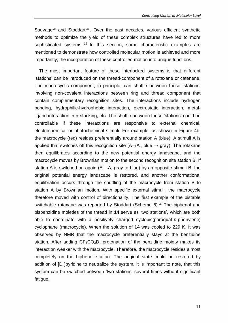
therefore moved with control of directionality. The first example of the bistable
switchable rotaxane was reported by Stoddart (Scheme 6).39 The biphenol and
bisbenzidine moieties of the thread in 14 serve as ‘two stations’, which are both
able to coordinate with a positively charged cyclobis(paraquat-p-phenylene)
cyclophane (macrocycle). When the solution of 14 was cooled to 229 K, it was
observed by NMR that the macrocycle preferentially stays at the benzidine
station. After adding CF3CO2D, protonation of the benzidine moiety makes its
interaction weaker with the macrocycle. Therefore, the macrocycle resides almost
completely on the biphenol station. The original state could be restored by
addition of [D5]pyridine to neutralize the system. It is important to note, that this
system can be switched between ‘two stations’ several times without significant
fatigue.

Chapter 1
12
Scheme 6. A bistable switchable rotaxane 144+/[14·2H]8+ and their HPLC spectra.
(Reproduced from ref. 38, copyright 2007 Wiley-VCH Verlag GmbH & Co. KGaA)
The previous example shows that it is possible to induce and control
directionality of the molecular motion of the macrocycle. Rather than ‘shuttling’
between ‘two stations’, if an additional control element is added, a unidirectional
rotary rotor could be achieved. This concept is illustrated in Figure 5.40 The
macrocycle (white) which contains two different recognition sites (A and B), a
hindering group K and a blocking group X serves as the ‘track’ ring. In the
beginning (state I), the ‘moving’ ring (red) stays with the most favorable site A of
the ‘track’ ring. Once the stimuli S1 is applied, site A is switched off to A’ (blue to
white) and the ‘moving’ ring then move away from it. There are two possible
direction for the ‘moving’ ring to reach site B, however, the presence of a blocking
group X makes anticlockwise rotation faster than clockwise rotation. After the
‘moving’ rings resides at site B (state II), another stimuli S2 can be applied to
remove the blocking group, together with the reset stimuli S-1 to switch on the
recognition ability of A (A’ to A, white to blue). Since the blocking group X has
been removed, the ‘moving’ ring prefers to move back to site A in a clockwise
fashion rather than anticlockwise in which it needs to pass over the hindering
group X. The original state can be completely reset after the blocking group K is

Controlling Motion at Molecular Level
13
put back by applying stimuli S-2. The directionality of the movement can be fully
controlled by the order of the input stimuli.
Figure 5. Schematic representation of an unidirectional rotary rotor. (Reproduced
from ref. 40, copyright 2005 AAAS)
Leigh and his co-workers built a unidirectional rotary rotor based on catenene
system 15 (Scheme 7).40 The larger ring (track ring) consists of two recognition
sites for the smaller ring (moving ring, red), a succinamide (SUC, green) and a
photoisomerizable fumaramide (FUM, blue) unit. A triphenylmethyl (TRI, pink)
and silyl (SIL, orange) group, both of which can be selectively
detached/reattached, serve as two bulky substituents that control the
directionality. In the starting isomer (Scheme 7, state I) the smaller ring stays with
the fumaramide site. After irradiation ( -
isomerized to the maleamide (MAL, grey) isomeric form (state II). After de-
silylation, the smaller ring moves in the clockwise direction to bind the
succinamide site (state III), followed by re-silylation. The maleamide unit can be
switched back to the fumaramide unit in the presence of piperidine (state IV).
This process is followed by de-tritylation/re-tritylation to generate another half-
rotation of the smaller ring in the clockwise direction back to the fumaramide unit,
forming the original state again (state I). The overall result is a 360° clockwise
rotation of the smaller ring around the larger one.

Chapter 1
14
Scheme 7. A rotary rotor based on catenene 15. (reproduced from ref. 40,
copyright 2005 AAAS)
This system is operated by four orthogonal stimulus; three chemical
transformations and a photochemical isomerization. The directionality of rotary
motion is then controlled by the sequence of the input. However, each input
requires a certain time to complete the reaction to convert the system from one
state to another state. This limitation makes this system to operate as a rotary
motor somewhat unpractical, since the rotor is very slow and cannot work
autonomously.
Recently, the same group reported the design, synthesis and operation of
rotaxane-based system 16 to synthesize peptides in a sequence-specific
manner.41 Inspired by ribosome in Nature, this system has several elements that
are analogous to ribosomal protein synthesis (Figure 6). This rotaxane contains a
macrocycle which possesses a reactive arm and a thread-axle that are attached
with amino acids by weak phenolic ester linkages. The sequence and spacing of
the axle-tethered amino acids enables sequence specific peptide synthesis,
Controlling Motion at Molecular Level
15
which is similar to the mRNA template in Nature. The thread also contains a
bulky terminal group that prevent the macrocycle sliding off the thread before the
synthesis of peptides is finished. The macrocycle is able to move along its axis in
a manner reminiscent of the ribosome subunits clamping to and moving along the
mRNA strand. A reactive arm that contains a cysteine derivative bearing a trityl
(Trt)-protected thiol group is attached to the macrocycle. It can detaches the
amino acids from the axle, passing them to the elongation site (a Boc-protected
amine at the end of a glycylglycine residue), where the resulting peptide oligomer
is synthesized in a single specific sequence, through native ligation.
Chapter 1
16
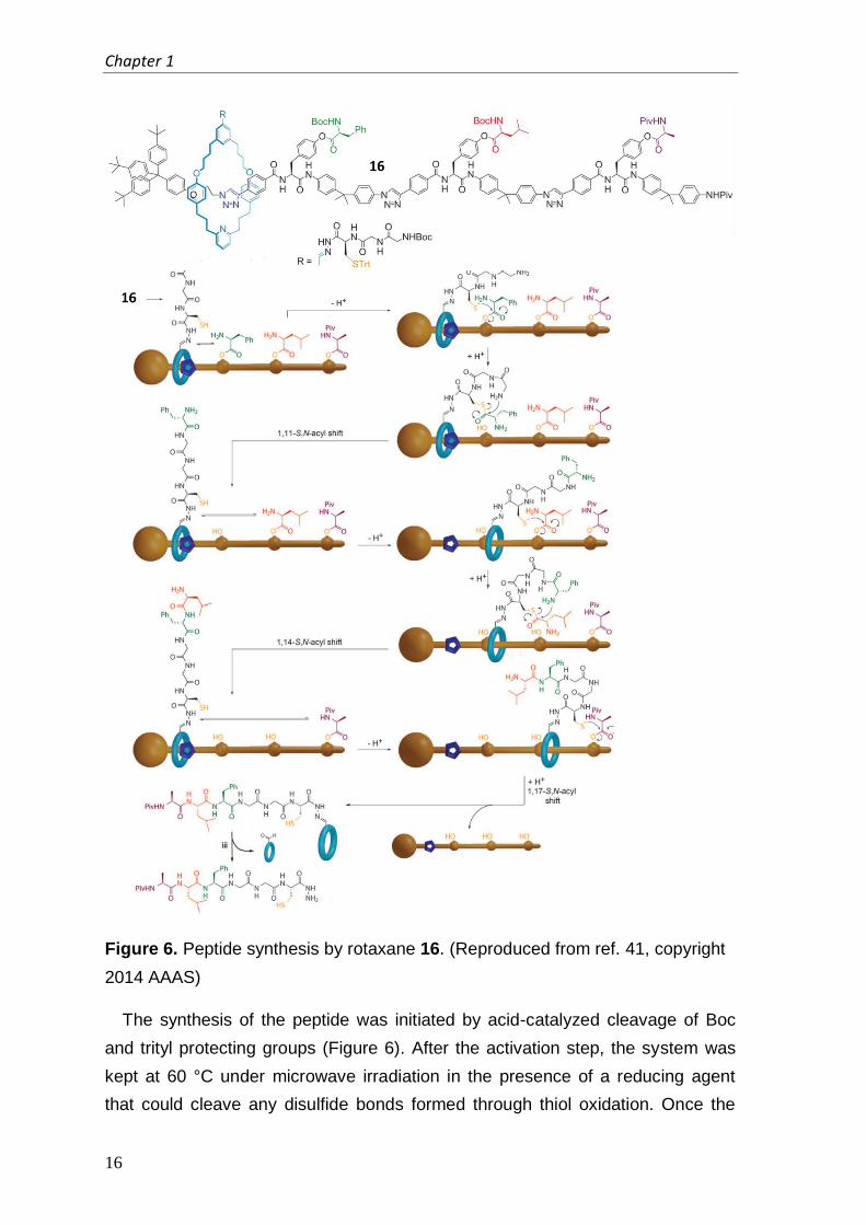
Figure 6. Peptide synthesis by rotaxane 16. (Reproduced from ref. 41, copyright
2014 AAAS)
The synthesis of the peptide was initiated by acid-catalyzed cleavage of Boc
and trityl protecting groups (Figure 6). After the activation step, the system was
kept at 60 °C under microwave irradiation in the presence of a reducing agent
that could cleave any disulfide bonds formed through thiol oxidation. Once the

Controlling Motion at Molecular Level
17
thiolate residue of the catalytic cysteine group is deprotected, it can undergo a
transacylation reaction with the first amino acid phenolic ester that blocks the ring
as it slides along the axle. The subsequently formed phenylalanine thioester then
transfers the amino acid to the glycylglycine amine group. This sequence
simultaneously transfers the amino acid to the end of the growing peptide and
regenerates the catalytic thiolate group, enabling it to cleave and transfer further
amino acids. Since the covalent bond that links the amino acid to the axle is
broken, the macrocycle is free to move further along the axle until it reaches the
next amino acid in the sequence. The entire process is then repeated again.
When the last amino acid on the axle is cleaved, the macrocycle slides off the
axle with the newly formed, full length peptide attached. After the detachment of
the macrocycle, the sequence-specific synthesis of the peptide is completed.
Compared to Nature’s ribosome, this system is much less efficient, taking on
average 12 h to make each amide bond while the ribosome is able to synthesize
15 amide bonds per second. However, as a primitive analog of the ribosome, this
system demonstrate the idea that the incorporation of controlled molecular
motion into a complex system can lead to a more advanced function.
1.4.3 Chemically driven molecular motors
Kelly and co-workers reported the first approach towards a synthetic
chemically driven rotary molecular motor with compound 17a.42 Their system
contains a three-bladed triptycene rotor and a helicene. This system is capable of
performing a controlled unidirectional 120° rotation through five consecutive steps.
The first step is to convert the amine group that is attached to the triptycene into
an isocyanate (18a) by addition of phosgene and triethylamine. Spontaneous
thermal rotation around the central bond can bring the isocyanate group close
enough to the hydroxyl group linked to helicene unit. Subsequently, the
isocyanate group reacts intramolecularly with the hydroxyl group to form a cyclic
urethane 19a. The formation of the urethane linkage irreversibly traps the system
in an undesirable strained conformation. This dynamically unstable conformation
is then followed by a unidirectional rotation step, where the helicene slips past the
part of the triptycene to afford a more stable conformation (19b). This rotation is
only allowed to proceed in one direction because the reverse direction is blocked
by the linked urethane bond. In the final step, hydrolysis of the urethane
generates a rotamer of the original starting atropisomer 17a. A 120° unidirectional
rotation around the central axis of the molecule is then completed. However, a

Chapter 1
18
serious drawback of this system is that only 120° rotation can be achieved and
this process is not repeatable. Although a lot of effort have been made to
optimize this system to achieve a repetitively unidirectional 360° rotation, the
attempts have been unsuccessful so far. 43
Scheme 8. Chemically driven motor 17. (Reproduced from ref. 42, copyright
1999 Macmillan Publishers Ltd)
Our group has reported a synthetic molecular motor that makes use of a
sequence of chemical transformations to perform 360° rotation in a repetitive
way.44 The full rotation of this molecular motor takes place through four distinct
stations (Figure 7). In station 20 and 22, rotation of the aryl moiety is restricted
because of the lactone formation. In station 21 and 23, the aryl unit cannot rotate
completely freely with respect to the naphthalene due to the steric hindrance
which prevents the aryl moiety from passing through the plane of the naphthalene
moiety. The rotary cycle consists of four chemically induced steps. Steps 1 and 3
are enantioselective reductions of the lactone by a chiral reagent. This
asymmetric ring opening reaction controls the direction of the rotation of the aryl
group. Steps 2 and 4 make use of the orthogonal chemical reactivity to conduct a
series of protection and deprotection of the phenol, followed by regioselective
ring formation. Reverse rotary direction can be achieved by using the opposite
enantiomer of the chiral reagent in steps 1 and 3 and different order of protection
and deprotection of the phenol in step 2 and 4.
Controlling Motion at Molecular Level
19
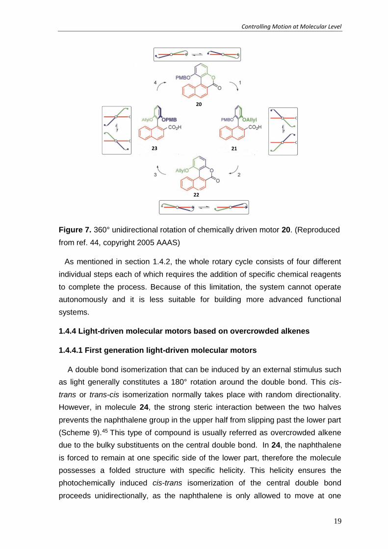
Figure 7. 360° unidirectional rotation of chemically driven motor 20. (Reproduced
from ref. 44, copyright 2005 AAAS)
As mentioned in section 1.4.2, the whole rotary cycle consists of four different
individual steps each of which requires the addition of specific chemical reagents
to complete the process. Because of this limitation, the system cannot operate
autonomously and it is less suitable for building more advanced functional
systems.
1.4.4 Light-driven molecular motors based on overcrowded alkenes
1.4.4.1 First generation light-driven molecular motors
A double bond isomerization that can be induced by an external stimulus such
as light generally constitutes a 180° rotation around the double bond. This cis-
trans or trans-cis isomerization normally takes place with random directionality.
However, in molecule 24, the strong steric interaction between the two halves
prevents the naphthalene group in the upper half from slipping past the lower part
(Scheme 9).45 This type of compound is usually referred as overcrowded alkene
due to the bulky substituents on the central double bond. In 24, the naphthalene
is forced to remain at one specific side of the lower part, therefore the molecule
possesses a folded structure with specific helicity. This helicity ensures the
photochemically induced cis-trans isomerization of the central double bond
proceeds unidirectionally, as the naphthalene is only allowed to move at one

Chapter 1
20
specific side of the lower half. The overall process results in an approximate 120°
rotation. In order to complete a full cycle (360°) unidirectional rotation, an
advanced design is required.
Scheme 9. Photochemically induced unidirectional rotation of an overcrowded
alkene 24.
The first example of light-driven molecular motor that is capable of performing
a repetitive 360° unidirectional rotation was reported by our group in 1999.46 This
system is based on a symmetric biphenanthrylidene 25 (Figure 8). There are
some important features of this system.47 First of all, the two identical halves are
linked by a central double bond which can serves as the axle of rotation.
Secondly, as mentioned above, due to the bulky substituents that disrupt the
planarity of the central double, the whole molecule is forced to adopt a twisted or
folded confirmation, which leads to the intrinsic helicity of the overcrowded alkene.
Most importantly, the stereogenic center at each half, which determines the
conformation of that part of the molecule, is a key element to control the
directionality of the rotary process. The methyl groups at the stereogenic center
of stable (3R,3'R)-(P,P)-trans-25 adopt a pseudo-axial orientation to minimize
steric interaction with the other half of the molecule. The unidirectional rotary
motion proceeds via a four-step cycle.

Controlling Motion at Molecular Level
21
Figure 8. Rotary cycle of light-driven first generation motor 25.
Irradiation ( > 280 nm) of stable (3R,3'R)-(P,P)-trans-25 generates a
photochemical trans/cis isomerization around the central double bond (Figure 8,
Step 1). This photoinduced isomerization causes a clockwise rotation of the
upper half with respect to the lower hall, resulting in the formation of unstable
(3R,3'R)-(M,M)-cis-25. This isomerization is a reversible process and continuous
irradiation leads to a photostationary state (PSS) where the ratio of stable trans
and unstable cis isomer remains unchanged (5:95). This PSS ratio strongly
depends on the absorbance of the two isomers and the quantum yield for
isomerization. Unstable (3R,3'R)-(M,M)-cis-25 is a thermally less stable isomer
because the methyl substituents at the stereogenic center are forced to adopt an
unfavorable pseudo-equatorial orientation. In order to release the steric strain, a
thermally activated step takes place at room temperature (Figure 9, step 2). In
this step, the methyl groups and the aromatic parts of both halves need to slide
past each other, with the substituents at either end of the double bond rotating in
the same direction to generate stable (3R,3'R)-(P,P)-cis-25. The helical
conformation of the molecule is inverted and the methyl groups at the stereogenic
centers are allowed to regain the more energetically favored pseudo-axial
orientation. It is important to note, that this thermal helix inversion step is not a
reversible process due to the large difference in free energy between the
unstable cis and stable cis isomers.48 This step ensures the unidirectionality of

Chapter 1
22
the rotary process. A second photochemical cis/trans isomerization takes place
when stable (3R,3'R)-(P,P)-cis-25 is irradiated ( > 280 nm), resulting in unstable
(3R,3'R)-(M,M)-trans-25 in which the stereogenic methyl groups are again placed
in a highly strained pseudo-equatorial orientation (Figure 8, step 3). Gentle
heating (60 °C) activates another irreversible thermal helix inversion step to
release the strain, completing the last step of the rotary process (Figure 8, step 4).
The original stable (3R,3'R)-(P,P)-trans-25 is regenerated and a full 360°
unidirectional rotation in clockwise fashion is then achieved. This rotary motion is
repetitive upon continuous energy (light and heat) input. It is important to note,
that in this system the directionality of rotation is fully determined by the
configuration of the stereogenic center: motor 25 with an (S) configuration at both
stereogenic centers will undergo rotation in the opposite direction (anticlockwise).
1.4.4.2 Second generation light-driven molecular motors
In the second generation molecular motors such as 26, the two halves
connected by the central double bond are not identical. 49 The upper half is
structurally similar to the first generation motors, whereas the lower half is
replaced by a tricyclic group. The unidirectional rotary motion operates similar to
the first generation motor, except for that the directionality is governed by a single
stereogenic center. The upper half of the motor can be considered as a rotator
and the lower half as a stator, while the central double serves as the rotary axle
(Scheme 10). Stable (M)-trans-26 adopts an specific intrinsic helicity due to the
significant steric crowding, which has been observed for the first generation
motor. The methyl group at the stereogenic center adopts a pseudo-axial
orientation to minimize steric interaction with the lower half of the motor. A
photochemical trans/cis isomerization of the central double bond takes place
when stable (M)-trans-26 is irradiated by UV light ( = 365 nm) (Scheme 10).
During this isomerization, the rotor part rotates anti-clockwise with respect to the
stator part, resulting in unstable (P)-cis-26 in which the overall helicity of the
molecules is changed. The (P)-cis-26 is a thermally unstable isomer since the
stereogenic methyl group is forced to adopt an unfavorable pseudo-equatorial
orientation, which pushes it towards the lower half. To release the steric strain, an
irreversible thermally activated step occurs where the methyl group and the
naphthalene upper half slip past the aromatic parts of the lower half, generating
stable (M)-cis-26. This step is accomplished by an inversion of the helicity of the
molecule and allows the stereogenic methyl group to regain the favored pseudo-

Controlling Motion at Molecular Level
23
axial orientation. Another photo-induced cis/trans isomerization which is followed
by a thermal helix inversion step completes the unidirectional 360° cycle. The
directionality of the rotation is controlled by the absolute configuration of the
stereogenic center and the use of the other enantiomer leads to opposite rotary
direction. Alternation of structure of the second generation motor offers several
practical advantages. For the synthesis of the first generation motor, McMurry
coupling is usually required. It often leads to low yields when employing sterically
hindered ketones and low functional group tolerances due to the harsh Lewis
acidic condition of McMurry coupling. The second generation motors can be
obtained via a different synthetic method, and distinct upper and lower half allows
selective functionalization on either part of the motor. This selective introduction
of functional groups provide ample opportunities for further application of these
motors.
Scheme 10. Rotary cycle of light-driven second generation motor 26.
1.4.4.3 Fine tuning the speed of light-driven molecular motors
The rotary cycle of light-driven molecular motors consists of two energetically
uphill photo-induced isomerizations and two energetically downhill thermal helix
inversion steps. As the photochemical step takes place on the picosecond

Chapter 1
24
timescale,50 the thermal helix inversion step is then the rate limiting step which
determines the rotary speed of the motor.50,51 The rate of this step is strongly
dependent on the steric interaction in the fjord region. Therefore, modification of
the motor structure to affect the interaction in the fjord region provides a facile
way to fine tune the speed of molecular motors (Scheme 11).
For the first generation motor, contraction of the six-membered ring (25) to a
five-membered ring (27) leads to an increased rate of thermal helix inversion. The
half-life (t1/2) of 25 at room temperature is about 233 h and motor 2752 exhibits a
dramatic increase of the rotary speed (t1/2 = 74 min). However, further reducing
the ring size from naphthalene (27) to p-xylene (28) does not results in faster
rotary speed. The half-life of 28 is found to be 40 h,53 while motor 27 has a half-
life of 74 min. The same structural modifications have also been applied to the
second generation motor. Substituting the six-membered rings in both upper and
lower half of motor 26 for five-membered ring affords a new type of second
generation motor 29. For motor 29a,54 a significant decrease of the barrier for the
thermal helix inversion step is observed and thus leads to a much faster rotary
speed (t1/2 = 3.2 min) compared to motor 26 (t1/2 = 166 h). For this structure, a
variety of R groups in the stereogenic center has also been investigated.55 Motor
29b (t1/2 = 5.7 ms) with a t-butyl group exhibits 3 x 10⁴ fold speed acceleration
compared to the methyl substituted motor 29a (t1/2 = 3.2 min). It means that motor
29b is able to perform 44 rotations per second, which is the same order of
magnitude as Nature’s benchmark rotary motor F1-ATPase, which is capable of
130 rotations per second. Decreasing the ring size from naphthalene to p-xylene
generates motor 30. Unlike the case of first generation motor 28, motor 30 (t1/2 =
15 s) is found to have an increased speed compared to motor 29a. It is worthy to
note, that substituting only the upper half of motor 26 from a six-member ring to a
cyclopentylidene (five-membered ring) results in motor 31 56 which shows a
significant increased rotary speed (t1/2 = 1.1 x 10⁻⁷ s).

Controlling Motion at Molecular Level
25
Scheme 11. Acceleration of molecular motors by modification of the struture.
It is crucial to develop light-driven molecular motors with a wide range of
speeds.48 On one hand, it is of great importance to build motors that are fast
enough to compete with Brownian motion which is a major issue for directional
motion of molecules. On the other hand, for the slow motor, the four rotary states
can be easily addressed and fully characterized. As mentioned before, each state
adopts a distinctive conformation and helicity, which can be used, for example,
for precise positioning of functional groups. Moreover, modification of the motor
structure, while keeping the unidirectional rotation, allows introduction of different
functional groups on the motor, which helps the application of molecular motors.
1.5 Functional light-driven molecular motors
1.5.1 Motors operating on surfaces
The motors discussed above all operate in solution and can be overwhelmed by
Brownian motion, which makes it difficult to gain both positional and orientational
order of the molecules. Therefore, it is hard to harness useful work from the
motor system. One possible solution to overcome this problem is to immobilize
the motors on a surface, converting the relative rotation of one part of the
molecule with respect to the other part to absolute rotation relative to the
surface.57

Chapter 1
26
Scheme 12. Surfaced bound light-driven molecular motors 32-34.
The first success was achieved, when motor 32 was immobilized on gold
particles to yield an azimuthal motor, in which the axis of rotation is perpendicular
to the surface (Scheme 12).58 In this motor, the lower half acts as the stator and it
is connected to the surface with two legs terminated with thiol groups. These two
attachment points prevent the free rotation with respect to the surface while
leaving the rotor function intact. It is also confirmed by CD and NMR
spectroscopy for the repetitive unidirectional rotation with respect to the surface.
XPS analysis gave a confirmation of the anchoring to the surface through two
attachment points. This work opened the door to the immobilization of other
motors on surfaces. Considering the fact that gold surface could act as an excited
state quencher, motor 33 was grafted to a quartz surface.59 Again, it was proven
by XPS that lower half (stator) of the molecule was grafted to the surface via two
points. Correlation of the photochemical and thermal behavior of the motor in the
monolayer to its counterpart in solution using CD spectroscopy showed the
molecular motor’s unidirectional rotary cycle. Not only azimuthal but also
altitudinal surface-grafted motor have been prepared. Motor 34 was attached to
an azide functioned quartz surface via the incorporation of two terminal acetylene
moieties as two legs of the molecule followed by “click” chemistry.60 Motor 34 is
shown to be able to undergo continuous light-driven rotation at room temperature
when assembled on quartz.
Controlling Motion at Molecular Level
27
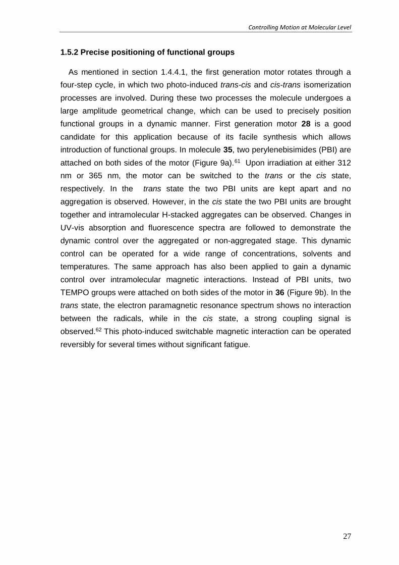
1.5.2 Precise positioning of functional groups
As mentioned in section 1.4.4.1, the first generation motor rotates through a
four-step cycle, in which two photo-induced trans-cis and cis-trans isomerization
processes are involved. During these two processes the molecule undergoes a
large amplitude geometrical change, which can be used to precisely position
functional groups in a dynamic manner. First generation motor 28 is a good
candidate for this application because of its facile synthesis which allows
introduction of functional groups. In molecule 35, two perylenebisimides (PBI) are
attached on both sides of the motor (Figure 9a).61 Upon irradiation at either 312
nm or 365 nm, the motor can be switched to the trans or the cis state,
respectively. In the trans state the two PBI units are kept apart and no
aggregation is observed. However, in the cis state the two PBI units are brought
together and intramolecular H-stacked aggregates can be observed. Changes in
UV-vis absorption and fluorescence spectra are followed to demonstrate the
dynamic control over the aggregated or non-aggregated stage. This dynamic
control can be operated for a wide range of concentrations, solvents and
temperatures. The same approach has also been applied to gain a dynamic
control over intramolecular magnetic interactions. Instead of PBI units, two
TEMPO groups were attached on both sides of the motor in 36 (Figure 9b). In the
trans state, the electron paramagnetic resonance spectrum shows no interaction
between the radicals, while in the cis state, a strong coupling signal is
observed.62 This photo-induced switchable magnetic interaction can be operated
reversibly for several times without significant fatigue.
Chapter 1
28
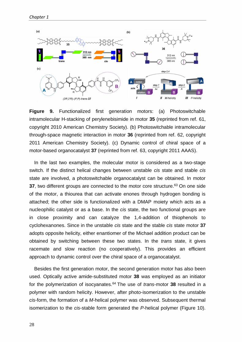
Figure 9. Functionalized first generation motors: (a) Photoswitchable
intramolecular H-stacking of perylenebisimide in motor 35 (reprinted from ref. 61,
copyright 2010 American Chemistry Society). (b) Photoswitchable intramolecular
through-space magnetic interaction in motor 36 (reprinted from ref. 62, copyright
2011 American Chemistry Society). (c) Dynamic control of chiral space of a
motor-based organocatalyst 37 (reprinted from ref. 63, copyright 2011 AAAS).
In the last two examples, the molecular motor is considered as a two-stage
switch. If the distinct helical changes between unstable cis state and stable cis
state are involved, a photoswitchable organocatalyst can be obtained. In motor
37, two different groups are connected to the motor core structure.63 On one side
of the motor, a thiourea that can activate enones through hydrogen bonding is
attached; the other side is functionalized with a DMAP moiety which acts as a
nucleophilic catalyst or as a base. In the cis state, the two functional groups are
in close proximity and can catalyze the 1,4-addition of thiophenols to
cyclohexanones. Since in the unstable cis state and the stable cis state motor 37
adopts opposite helicity, either enantiomer of the Michael addition product can be
obtained by switching between these two states. In the trans state, it gives
racemate and slow reaction (no cooperatively). This provides an efficient
approach to dynamic control over the chiral space of a organocatalyst.
Besides the first generation motor, the second generation motor has also been
used. Optically active amide-substituted motor 38 was employed as an initiator
for the polymerization of isocyanates.64 The use of trans-motor 38 resulted in a
polymer with random helicity. However, after photo-isomerization to the unstable
cis-form, the formation of a M-helical polymer was observed. Subsequent thermal
isomerization to the cis-stable form generated the P-helical polymer (Figure 10).

Controlling Motion at Molecular Level
29
In this case, the motor serves as a multistage trigger. The change in chirality of
the molecular motor between the unstable cis state and the stable cis state leads
to a change in folding of a dynamic polymer.
Figure 10. Schematic illustration of the reversible induction and inversion of the
helicity of a polymer by a single light-driven molecular.
1.5.3 Directed motion
Recently, our group made a nanocar. In this design, molecule 39 consists of
four unidirectional rotary motors and two rigid carbazole cores (Figure 11). The
four molecular motors can undergo continuous rotary motion upon the application
of external stimuli and therefore act as molecular wheels as well as the engine of
the nanocar. Through the structural changes of the four motors during their
rotation, molecule 39 is expected to move across the surface in a directed way
via a paddlewheel type movement. Nanocar 39 was deposited on a copper
surface and visualized by low temperature ultra-high vacuum STM.65 Instead of
UV-light, the isomerization of central double bond was induced electrochemically
with the STM tip. By repeatedly applying a voltage to a molecule, multiple
consecutive isomerizations take place, which causes the molecule to move
across the surface with directional preference, depending on the stereochemistry
of the molecule. This example shows that the unidirectional rotation of the
molecular motor can be applied to achieve translational motion.

Chapter 1
30
Figure 11. Electrically driven nanocar 39: (a) Molecular structure. (b)
Paddlewheel type motion. (reprinted from ref. 65, copyright 2011 Macmillan
Publishers Ltd)
1.6 Conclusions and outline of the thesis
Nature has provided a large number of fascinating examples which
demonstrate how molecular motion can be operated with high efficiency and
precise control. Two characteristic natural molecular motors are described since
they are the major sources of inspiration for chemists to develop artificial
molecular systems that could mimic or partially mimic the remarkable features
present in natural systems. Efforts towards directly employing biological motors
are discussed. However, the limited condition of using biological motors ex vivo
leads to the development of synthetic molecular rotors and motors. The synthetic
systems are based on organic molecules which allow structural modification for
advanced functionalities. Furthermore, synthetic molecular rotors and motors are
capable of operating in a wide range of conditions. Two rotor systems mimicking
the design of macroscopic gyroscope are described. The speed of these two
rotor systems could be tuned with several methods and the introduction of polar
functional groups provides the possibility to achieve controlled directional rotation.
However, no successful example is reported so far. Interlocked systems based
on rotaxanes and catenenes are another important design to control molecular
motion. The macrocycle is able to move along the ‘thread’ by applying external
stimuli and the direction of the movement could be controlled. Two important
chemically driven molecular motors are also discussed. Both are able to perform
unidirectional rotation upon a series of chemical reactions induced by different
reactants. The rotary direction can be controlled by the order of the chemical

Controlling Motion at Molecular Level
31
input. One major drawback of these systems is that each step of the rotation
requires a specific reaction, which limits the system rotating autonomously.
The light-driven molecular motor based on sterically overcrowded alkene is also
discussed. It can perform repetitively unidirectional rotation by applying UV light
and heat. The direction of its rotation can be controlled by the stereochemistry of
the motor. The rotary speed can be tuned by simple modification of the core
structure. It is very crucial to develop motors with different speed because in
some cases the fast rotation of motor is needed65 while in other cases the
relatively slow process of each rotary step is required.63 Moreover, motors have
been attached to surfaces both in azimuthal and altitudinal orientation, without
compromising the rotary function. This achievement is an important step for
further application since the relatively unidirectional rotation in solution has been
converted into absolutely unidirectional rotary motion on a surface. Furthermore,
the incorporation of different functional groups into the motor core structure lead
to a variety of functional systems in which the rotary motion of these motors plays
a crucial role.
Despite a lot of efforts towards the application of molecular motors, there is still
major room for improvements and further developments. In this thesis, the goal is
to apply light-driven molecular motors as a tool to control molecular motion and to
build up advanced functional systems. In the following chapters, multicomponent
systems that are based on molecular motors will be described and their function
will be evaluated by using different spectroscopic methods and microscopy
techniques.
Chapter 2 describes the design and synthesis of an overcrowded alkene-based
photo-responsive amphiphile. The photo-responsive behavior upon irradiation
with UV-light in solution is studied by UV/vis and 1H-NMR spectroscopies. Its self-
assembly and disassembly in water is studied by cryo-TEM, confocal fluorescent
microscopy and epifluorescence microscopy.
Chapter 3 focuses on the development of a novel, light-responsive, self-
assembled nanotube system based on amphiphilic light-driven molecular motors.
Two molecular motors with different rotary speed are designed and synthesized.
The rotary motion of these two motors in solution is monitored by UV/vis and 1H-
NMR spectroscopies. Cryo-TEM is employed to study the self-assemblies of
these two motors in water.

Chapter 1
32
In chapter 4, a series of first generation light-driven molecular motors with rigid
substituents of varying length is synthesized to act as ‘molecular stirrers’. Their
rotary motion is studied by 1H-NMR and UV-vis absorption spectroscopies in a
variety of solvents with different viscosity.
Chapter 5 focuses on the concept and design of an advanced system aiming at
direct visualization of the rotary motion of a light-driven molecular motor on a
surface. The required components of this system are discussed and the
interactions between these components are studied.
Chapter 6 describes the first attempts to directly visualize the rotary motion of a
light-driven molecular motor on a surface. The motor is equipped with a perylene
bisimide as a fluorescent tag and is attached on quartz via ‘click chemistry’. Its
orientation on surface is studied by defocused wide-field fluorescence
microscopy.
In chapter 7, a novel method of grafting light-driven molecular motors on
surface is described. Molecular motors can be assembled on quartz via tetrapod
attachment by non-covalent interactions. The orientation of molecular motors on
quartz is studied by defocused wide-field fluorescence microscopy.
Chapter 8 describes the studies on textures of cholesteric droplets controlled by
photo-switching chirality at the molecular level.
Controlling Motion at Molecular Level
33
References:
1 Schliwa, M.; Woehlke, G. Nature 2003, 422, 759.
2 Schliwa, M. Molecular Motors, Wiley-VCH, Weinheim, Germany, 2003
3 Boyer, P. D. Nature 2006, 402, 247.
4 Bray, D. Cell Movements: From Molecules to Motility, Garland, New York,
1992
5 Berg, J. M., Tynoczko, J. L., Styer, L. Biochemistry 5th ed W. H. Freeman,
New York, 2006
6 (a) Hess, H.; Bachand, G. D. Nanotoday 2005, 8, 22 (b) Hess, H.; Vogel, V.,
Rev. Mol. Biotechnol. 2001, 82, 67.
7 Feynman, There’s Plenty of Room at the Bottom,
www.its.caltech.edu/~feynman
8 (a) Stoddart, J. F. Acc. Chem. Res. 2001, 34, 410. (b) Sauvage, J.-P. (ed.)
Molecular Machines and Motors, Springer, Berlin, 2001; (c) Feringa, B. L.
(ed.) Molecular Switches, Wiley-VCH, Weinheim, Germany, 2001 (d) Kinbara,
K. & Aida, T. Chem. Rev. 2005, 105, 1377.
9 Whitesides, G. M. Sci. Am. 2001, 285, 78.
10 (a) Yoshida, M.; Muneyuki, E.; hisabory, T. Nat. Rev. Mol. Cell Biol. 2001, 2,
669. (b) Grabe, H.; Wang, H.; Oster, G. Biophys. J. 2000, 78, 2798. (c) Itoh,
H.; Takahashi, E.; Hisabori, T.; Adachi, K.; Noji, H.; Yasuda, R.; Yoshida, M.;
Kinosita, K. Nature 2004, 427, 465.
11 Wang, H.; Oster, G. Nature 1998, 396, 279.
12 Berry, R. Molecular Motors: Chapter 4, The Bacterial Flagellar Motor, M.
Schliwa(Ed); Wiley-VCH, Weinheim, 2003, 112.
13 Berg, H. C. Ann. Rev. Biochem. 2003, 72, 19.
14 Vale, R. D.; Milligan, R. A. Science 2000, 288, 88.
15 Hiratsuka, Y.; Tada, T.; Oiwa, K.; Kanayama, T.; Uyeda, Q. P. Biophys. J.
2001, 81, 1555.
16 Clemmens, J. Langmuir 2003, 19, 10967.
17 Bunk R.; Sundberg M.; Mansson A.; Nicholls I. A.; Tagerud S.; Montelius L.
Nanotechnology 2005, 16, 710.
18 Darnton, N.; Turner, L.; Breuer, K.; Berg, H. C. Biophys. J. 2004, 86, 1863.
19 Hiratsuka, Y.; Miyata, M.; Tada, T.; Uyeda, T. Q. Proc. Natl. Acad. Sci. 2006,
103, 1361.

Chapter 1
34
20 Shima, T.; Hampel, F.; Gladysz, J. A. Angew. Chem. Int. Ed. 2004, 43, 5537.
21 Nawara, A. J.; Shima, T.; Hampel, F.; Gladysz, J. A. J. Am. Chem. Soc. 2006,
128, 4962.
22 Wang, L.; Hampel, F.; Gladysz, J. A. Angew. Chem. Int. Ed. 2006, 45, 4372.
23 Wang, L.; Shima, T.; Hampel, F.; Gladysz, J. A. Chem. Commun. 2006, 4075.
24 Hess, G. D.; Hampel, F.; Gladysz, J. A. Organometallics, 2007, 26, 5129.
25 Sipachev, V. A.; Khaikin, L. S.; Crikina, O. E.; Nikitin, V. S.; Traettberg, M. J.
Mol. Struc. 2000, 523, 1.
26 Dominguez, Z.; Dang, H.; Strouse, M. J.; Garcia-Garibay, M. A. J. Am. Chem.
Soc. 2002, 124, 2398.
27 Nuñez, J. E.; Khuong, T-A. V.; Campos, L. M.; Farfan, N.; Dang, H.; Karlen. S.
D.; Garcia-Garibay, M. A. Cryst. Growth. Des. 2006, 6, 866.
28 Khuong, T-A V.; Dang, H.; Jarowski, P. D.; Maverick, E. F.; Garcia-Garibay, M.
A. J. Am. Chem. Soc. 2007, 129, 839.
29 Khuong, T-A. V.; Zepeda. G.; Ruiz, R.; Khan, S. I.; Garcia-Garibay, M. A.
Cryst. Growth. Des. 2004, 4, 15
30 Nuñez, J. E.; Natarajan, A.; Garcia-Garibay, M. A. Org. Lett. 2007, 9, 3559.
31 Godinez, C. E.; Zepeda, G.; Mortko, C. J.; Dang, H.; Garcia-Garibay, M. A. J.
Org. Chem. 2004, 69, 1652.
32 Dominguez, Z.; Khuong, T-A. V.; Dang, H.; Nuñez, J. E.; Sanrame, S. N.;
Garcia-Garibay, M. A. J. Am. Chem. Soc. 2003, 125, 8827.
33 Santillán, R.; Karlen, S. D.; Dang, H.; Garcia-Garibay, M. A. J. Mex. Chem.
Soc. 2008, 52, 125.
34 Rodriguez-Molina, B.; Ochoa, M. E.; Farfán, N.; Santill, R.; Garcia-Garibay, M.
A. J. Org. Chem. 2009, 74, 8554.
35 Karlen, S. D.; Ortiz, R.; Chapman. O. L.; Garcia-Garibay, M. A. J. Am. Chem.
Soc. 2005, 127, 6554.
36 Dietrich-Buchecker, C. O.; Sauvage, J. P. Chem. Rev. 1987, 87, 795.
37 Balzani, V.; Lopez-Gomez, M.; Stoddart, J. F. Acc. Chem. Res. 1998, 31, 405.
38 Kay, E. R.; Leigh, D. A.; Zerbetto, F. Angew. Chem. Int. Ed. 2007, 46, 72.
39 Bissell, R. A.; Cordova, E.; Kaifer, A. E.; Stoddart, J. F. Nature 1994, 369, 133.
40 Hernandez, J. V.; Kay, E. R.; Leigh, D. A.; Science 2004, 306, 1532.
41 Lewandowski, B.; De Bo, G.; Ward, J. W.; Papmeyer, M.; Kuschel, S.;
Aldegunde, M. J.; Gramlich, M. E.; Heckmann, D.; Goldup, M. S.; D’Souza,
M. D.; Fernandes, A. E.; Leigh D. Science 2013, 339, 189.
Controlling Motion at Molecular Level
35
42 Kelly, T. R.; De Silva, H.; Silva, R. A. Nature 1999, 401, 150.
43 Kelly, T. R.; Cai, X.; Damkaci, F.; Panicker S. B.; Tu, B.; Bushell, S. M.;
Cornella, I.; Piggott, M. J.; Salives, R.; Cavero, M.; Zhao, Y.; Jasmin, S. J. Am.
Chem. Soc. 2007, 129, 376.
44 Flectcher S. P.; Dumur, F.; Pollard, M. M.; Feringa, B. L. Science 2005, 310,
80.
45 Feringa, B. L.; van Delden, R. A.; ter Wiel, M. K. J. Molecular Switch, Wiley-
VCH, Weinheim, Germany, 2001
46 Koumura, N.; Zijlstra, R. W. J.; van Delden, R. A.; Harada, N.; Feringa, B. L.
Nature 1999, 401, 152.
47 Feringa, B. L. Acc. Chem. Res. 2001, 34, 504.
48 Pollard, M. M.; Klok, M.; Pijper, D.; Feringa, B. L. Adv. Funct. Mater. 2007, 17,
718.
49 Koumura, N.; Geertsema, E. M.; Meetsma, A.; Feringa, B. L. J. Am. Chem.
Soc. 2000, 122, 12005.
50 (a)Zijlstra, R. W. J.; van Duijnen, P. T.; Feringa, B. L.; Steffen, T.; Duppen, K.;
Wiersma, D. A. J. Phys. Chem. A 1997, 101, 9828. (b) Schuddeboom, W.;
Jonker, S. A.; Warman, J. M.; de Haas, M. P.; Vermeulen, M. J. W.; Jager, W.
F.; de Lange, B.; Feringa, B. L.; Fessenden, R. W. J. Am. Chem. Soc. 1993,
115, 3286. (c) Augulis, R.; Klok M.; Feringa B. L.; van Loosdrecht, P. H. M.
Phys. Stat. Sol. C 2009, 6, 181. (d) Conyard, J.; Addison, K.; Heisler, I. A.;
Cnossen, A.; Browne, W. R.; Feringa, B. L.; Meech, S. R. Nat. Chem. 2012, 4,
547.
51 (a) Klok, M.; Browne, W. R.; Feringa, B. L. Phys. Chem. Chem. Phys. 2009,
11, 9124. (b) Geertsema, E. M.; van der Molen, S. J.; Martensc, M.; Feringa, B.
L. Proc. Natl. Acad. Sci. USA 2009, 106, 16919.
52 ter Wiel, M. K. J.; van Delden, R. A.; Meetsma, A.; Feringa, B. L. J. Am. Chem.
Soc. 2003, 125, 15076.
53 Pollard, M. M.; Meetsma, A.; Feringa, B. L. Org. Biomol Chem. 2008, 6, 507.
54 Vicario, J.; Meetsma, A.; Feringa, B. L. Chem. Comm. 2005, 5910.
55 Vicario, J.; Walko, M.; Meetsma, A.; Feringa, B. L. J. Am Chem. Soc. 2006,
128, 5127.
56 Klok, M.; Boyle, N.; Pryce, M. T.; Meetsma, A.; Browne, W. R.; Feringa, B. L. J.
Am Chem. Soc. 2008, 130, 10484.

Chapter 1
36
57 Katsonis, N.; Lubomska, M.; Pollard, M. M.; Feringa, B. L.; Rudolf, P. Prog.
Surf. Sci. 2007, 82, 407.
58 (a) van Delden, R. A.; ter Wiel, M. K. J.; Pollard, M. M.; Vicario, J.;
Koumura,N.; Feringa, B. L. Nature 2005, 437, 1337. (b) Pollard, M. M.; ter
Wiel, M. K. J.; van Delden, R. A.; Vicario, J.; Koumura, N.; van den Brom, C.
R.; Meetsma, A.; Feringa, B. L. Chem. Eur. J. 2008, 14, 11610.
59 Pollard, M. M.; Lubomska, M.; Rudolf, P.; Feringa, B. L. Angew. Chem., Int.
Ed. 2007, 46, 1278.
60 London, G.; Carroll, G. T.; Landaluce, T. F.; Pollard, M. M.; Rudolf, P.; Feringa,
B. L. Chem. Comm. 2009, 1712.
61 Wang, J.; Kulago, A.; Browne, W. R.; Feringa, B. L. J. Am. Chem. Soc. 2010,
132, 4191.
62 Wang, J.; Hou, L.; Browne, W. R.; Feringa, B. L. J. Am. Chem. Soc. 2011, 133,
8162.
63 Wang, J.; Feringa, B. L. Science 2011, 331, 1429.
64 Pijper, D.; Feringa, B. L. Angew. Chem., Int. Ed. 2007, 46, 3693.
65 Kudernac, T.; Ruangsupapichat, N.; Parschau, M.; Macia, B.; Katsonis, N.;
Harutyunyan, S. R.; Ernst, K. H.; Feringa, B. L. Nature 2011, 479, 208.