university of groningen kinetics, selectivity and scale up of … · · 2016-03-051.1...
TRANSCRIPT

University of Groningen
Kinetics, selectivity and scale up of the Fischer-Tropsch synthesisvan der Laan, Gerard Pieter
IMPORTANT NOTE: You are advised to consult the publisher's version (publisher's PDF) if you wish to cite fromit. Please check the document version below.
Document VersionPublisher's PDF, also known as Version of record
Publication date:1999
Link to publication in University of Groningen/UMCG research database
Citation for published version (APA):van der Laan, G. P. (1999). Kinetics, selectivity and scale up of the Fischer-Tropsch synthesis Groningen:s.n.
CopyrightOther than for strictly personal use, it is not permitted to download or to forward/distribute the text or part of it without the consent of theauthor(s) and/or copyright holder(s), unless the work is under an open content license (like Creative Commons).
Take-down policyIf you believe that this document breaches copyright please contact us providing details, and we will remove access to the work immediatelyand investigate your claim.
Downloaded from the University of Groningen/UMCG research database (Pure): http://www.rug.nl/research/portal. For technical reasons thenumber of authors shown on this cover page is limited to 10 maximum.
Download date: 16-06-2018

�
� �� !�#"��%$&�(')���
1.1 Fischer-Tropsch(FT) Process
Coal and naturalgascan be utilized as feedstockof the chemicalindustry and thetransportationfuelsmarket. Theconversionof naturalgasto hydrocarbons(Gas-To-Liquidsroute)is currentlyoneof themostpromisingtopicsin theenergy industrydueto economicutilizationof remotenaturalgasto environmentallycleanfuels,specialtychemicalsandwaxes.Alternatively, coalor heavy residuescanbeusedonsiteswheretheseareavailableat low costs.Theresourcesof coalandnaturalgasarevery large,seeTable1.1. Coalandnaturalgascanbeconvertedinto synthesisgas,a mixtureofpredominantlyCO andH2, by eitherpartial oxidationor steamreformingprocesses.Possiblereactionsof synthesisgasareshown in Figure1.1.
Natural gasCoal
CO+H2
Hydrocarbons
CH*
3OH
Higher Alcoholsand oxygenates
F-T+
Figure1.1 Possiblereactionsfrom synthesisgas.
Table1.1 World fossil fuel reservesandconsumption(EJ,1018J) [1].
Reserves Consumption(1991)
Coal(1991) 27, 185 69- 91Crudeoil (1992) 6 , 054 143- 67Naturalgas(1992) 4 , 512 79- 44
1

2 CHAPTER 1
Table1.2 Major overall reactionsin theFischer-Tropschsynthesis.
Main reactions1. Paraffins (2n . 1)H2 + nCO / CnH2n0 2 + nH2O2. Olefins 2nH2 + nCO / CnH2n + nH2O
3. Watergasshift reaction CO+ H2O / 1 CO2 + H2
Sidereactions4. Alcohols 2nH2 + nCO / CnH2n0 2O + 2 n 3 14 H2O5. Boudouardreaction 2CO / C + CO2
Catalystmodifications
6. Catalystoxidation/reduction a.MxOy + yH2/ 1 yH2O + xM
b. MxOy + yCO / 1 yCO2 + xM
7. Bulk carbideformation yC + xM / 1 MxCy
Theconversionof thesynthesisgasto aliphatichydrocarbonsovermetalcatalystswasdiscoveredby FranzFischerandHansTropschat theKaiserWilhelm InstituteforCoalResearchin Mullheim in 1923[2, 3]. They provedthatCO hydrogenationoveriron, cobaltor nickel catalystsat 180-250 ˚C andatmosphericpressureresultsin aproductmixtureof linearhydrocarbons.TheFischer-Tropschproductspectrumcon-sistsof a complex multicomponentmixtureof linearandbranchedhydrocarbonsandoxygenatedproducts.Main productsarelinear paraffins and -olefins. The overallreactionsof the Fischer-Tropschsynthesisaresummarizedin Table1.2. Thehydro-carbonsynthesisis catalyzedby metalssuchascobalt,iron, andruthenium.Both ironandcobaltareusedcommerciallythesedaysata temperatureof 200to 300 ˚C andat10 to 60barpressure[4, 5].
Thereactionsof theFT synthesison iron catalystscanbesimplifiedasa combi-nationof theFT reactionandthewatergasshift (WGS)reaction:
CO .52 1 . m6 2n4 H2 / 16 nCnHm . H2O 2 FT 4 - 7 HFT= 165kJ/mol (1.1)
CO . H2O / 1 CO2 . H2 2 WGS4 - 7 HWGS= 41.3kJ/mol (1.2)
wheren is theaveragecarbonnumberandm is theaveragenumberof hydrogenatomsof thehydrocarbonproducts.Wateris a primaryproductof theFT reaction,andCO2
canbeproducedby theWGSreaction.TheWGSactivity canbehighoverpotassium-promotediron catalystsandis negligible overcobaltor rutheniumcatalysts.

INTRODUCTION 3
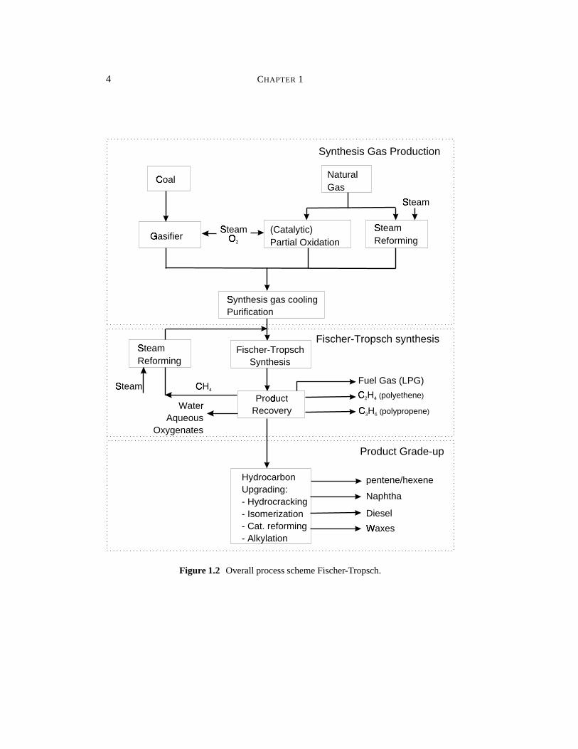
Figure1.2 shows a block diagramof theoverall Fischer-Tropschprocessconfig-uration.Thecommercialprocessinvolvesthreemainsections,namely:synthesisgasproductionandpurification,Fischer-Tropschsynthesis,andproductgrade-up.Thesesubjectsaredescribedin moredetailbelow. Choi et al. [6] givesa capitalcostbreak-down of thesethreeindividual processsectionsfor a 45,000bbl/dayFT plant. Thesynthesisgaspreparation(thatis air separationplant,partialoxidation,steamreform-ing of naturalgas,andsyngascooling)is about66 % of thetotalon-sitecapitalcosts.TheFT synthesissectionconsistingof FT slurry reactors,CO2 removal, synthesisgascompressionandrecycle,andrecovery of hydrogenandhydrocarbonsis 22 % of thetotal costs. Finally, the upgradingandrefining sectionof hydrocarbonsis about12%. Consequently, cost reductionof synthesisgasproductionis the mostbeneficial.Note,however, thatatafixedproductionratetheselectivity of theFT processdirectlyaffectsthesizeof thesyngasgenerationsection.A high selectivity of theFT processto desiredproductsis of utmostimportanceto theoveralleconomics.
1.1.1 SynthesisGasProduction
Synthesisgascanbe obtainedby steamreformingor (catalytic)partial oxidationoffossil fuels: coal,naturalgas,refineryresidues,biomassor industrialoff-gases.Thecompositionof syngasfrom thevariousfeedstocksandprocessesis givenin Table1.3[7, 8]. Synthesisgascanbeobtainedfrom reformingof naturalgaswith eithersteamor carbondioxide,or by partialoxidation.Themostimportantreactionsare:
Steamreforming CH4 + H2O / 1 CO+ 3H2
CO2 reforming CH4 + CO2/ 1 2CO+ 2H2
Partial oxidation CH4 + 12O2 / CO+ 2H2
Watergasshift reaction CO+ H2O / 1 CO2 + H2
Usually, a combinationof synthesisgasproductionprocessesis usedto obtainsyn-thesisgaswith astoichiometricratioof hydrogenandcarbonmonoxide.
Synthesisgasproducedin moderncoal gasifiers(Shell/Koppersor Texacogasi-fiers)andfrom heavy oil residueshasa high CO contentin comparisonto synthesisgasfrom naturalgas.If synthesisgaswith a H2/CO ratiobelow 2 is used,thecompo-sition is notstoichiometricfor theFischer-Tropschreactions(seeTable1.2).Thenthewatergasshift reactionis importantto changetheH2/COratio to 2. Figure1.3showstheapplicationrangesfor iron (high WGS-activity) andcobaltcatalysts(no WGSac-tivity) [10]. Inexpensive iron catalystsin comparisonto cobaltcandirectly convert
4 CHAPTER 1
Coal8 Natural
Gas
Steam9Reforming
Steam9Reforming
Gasifier: (Catalytic)
Partial Oxidation
Steam;
Steam;
Steam;
O<
2
Synthesis gas cooling;Purification
Fischer-TropschSynthesis
Product=Recovery
HydrocarbonUpgrading:- Hydrocracking- Isomerization- Cat. reforming- Alkylation
CH>
4C>
2H4 (polyethene)
C>
3H6 (polypropene)
Fuel Gas (LPG)
Naphtha
pentene/hexene
Diesel
Waxes?
Water@Aqueous
Oxygenates
Synthesis Gas Production
Fischer-Tropsch synthesis
Product Grade-up
Figure1.2 OverallprocessschemeFischer-Tropsch.
INTRODUCTION 5
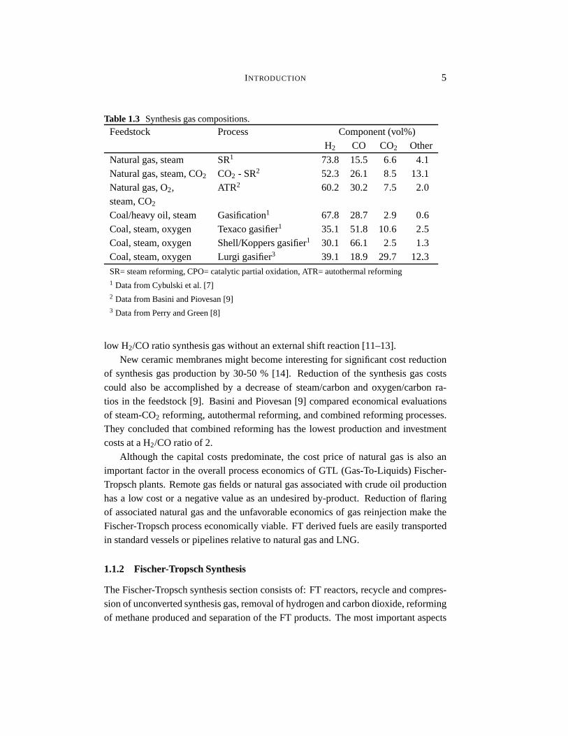
Table1.3 Synthesisgascompositions.
Feedstock Process Component(vol%)H2 CO CO2 Other
Naturalgas,steam SR1 73.8 15.5 6 - 6 4 - 1Naturalgas,steam,CO2 CO2 - SR2 52.3 26.1 8 - 5 13- 1Naturalgas,O2, ATR2 60.2 30.2 7 - 5 2 - 0steam,CO2
Coal/heavy oil, steam Gasification1 67.8 28.7 2 - 9 0 - 6Coal,steam,oxygen Texacogasifier1 35.1 51.8 10- 6 2 - 5Coal,steam,oxygen Shell/Koppersgasifier1 30.1 66.1 2 - 5 1 - 3Coal,steam,oxygen Lurgi gasifier3 39.1 18.9 29- 7 12- 3SR=steamreforming,CPO=catalyticpartialoxidation,ATR= autothermalreforming1 Datafrom Cybulski etal. [7]2 Datafrom BasiniandPiovesan[9]3 Datafrom PerryandGreen[8]
low H2/COratiosynthesisgaswithoutanexternalshift reaction[11–13].New ceramicmembranesmight becomeinterestingfor significantcostreduction
of synthesisgasproductionby 30-50% [14]. Reductionof the synthesisgascostscould also be accomplishedby a decreaseof steam/carbonand oxygen/carbonra-tios in the feedstock[9]. Basini andPiovesan[9] comparedeconomicalevaluationsof steam-CO2 reforming,autothermalreforming,andcombinedreformingprocesses.They concludedthat combinedreforminghasthe lowestproductionandinvestmentcostsataH2/COratioof 2.
Although the capital costspredominate,the costprice of naturalgasis alsoanimportantfactorin theoverall processeconomicsof GTL (Gas-To-Liquids)Fischer-Tropschplants.Remotegasfieldsor naturalgasassociatedwith crudeoil productionhasa low costor a negative valueasan undesiredby-product. Reductionof flaringof associatednaturalgasandtheunfavorableeconomicsof gasreinjectionmake theFischer-Tropschprocesseconomicallyviable. FT derivedfuelsareeasilytransportedin standardvesselsor pipelinesrelative to naturalgasandLNG.
1.1.2 Fischer-TropschSynthesis
TheFischer-Tropschsynthesissectionconsistsof: FT reactors,recycle andcompres-sionof unconvertedsynthesisgas,removalof hydrogenandcarbondioxide,reformingof methaneproducedandseparationof theFT products.Themostimportantaspects

6 CHAPTER 1
0.4A
0.6A
1.4 1.6 1.8 2.0B
0.8A
1.0 1.2
Cobalt (Co)C
Iron (Fe)
NaturalDGas & Steam
NaturalDGasAsphaltE
Fuel Oil
NaphthaFVacuumDResidue
CoalG
H2/CO
Figure1.3 Feedstocksandcatalysts[10].
for developmentof commercialFischer-Tropschreactorsarethe high reactionheatsandthelargenumberof productswith varyingvaporpressures(gas,liquid, andsolidhydrocarbons).Themainreactortypeswhichhavebeenproposedanddevelopedafter1950are[5, 15,16]:
1. Three-phasefluidized (ebulliating) bedreactorsor slurry bubblecolumnreac-tors with internalcooling tubes(SSPD:Sasol;GasCat:Energy International,AGC-21:Exxon,seeFigure1.4a)
2. Multitubularfixedbedreactorwith internalcooling(Arge:Sasol;SMDS:Shell,seeFigure1.4b)
3. Circulatingfluidizedbedreactorwith circulatingsolids,gasrecycleandcoolingin thegas/solidrecirculationloop (Synthol:Sasol)(Figure1.4c)
4. Fluidizedbedreactorswith internalcooling(SAS:Sasol)(Figure1.4d)
Sie[5] comparedtheadvantagesanddisadvantagesof thetwomostfavoritereactorsystemsfor the Fischer-Tropschsynthesisof high molecularweight products: thatis the multitubular trickle bedreactorandthe slurry bubblecolumnreactor. Majordrawbacksof thebubblecolumnarerequirementsfor continuousseparationbetween
INTRODUCTION 7
coolantHcoolantHcoolantH
slurryI
G
coolantHG
GG
GG
G L
L
a.J b.K
c.L d.M
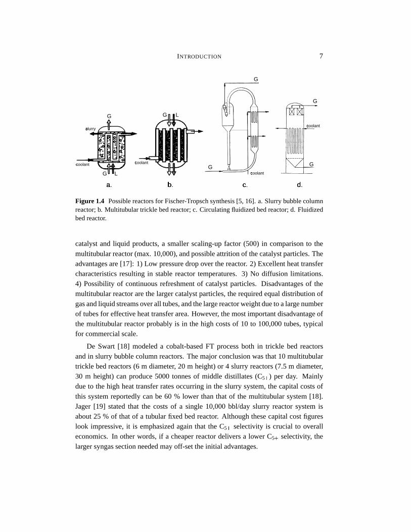
Figure1.4 Possiblereactorsfor Fischer-Tropschsynthesis[5, 16]. a. Slurrybubblecolumnreactor;b. Multitubular trickle bedreactor;c. Circulatingfluidizedbedreactor;d. Fluidizedbedreactor.
catalystand liquid products,a smallerscaling-upfactor (500) in comparisonto themultitubular reactor(max.10,000),andpossibleattritionof thecatalystparticles.Theadvantagesare[17]: 1) Low pressuredropover thereactor. 2) Excellentheattransfercharacteristicsresultingin stablereactortemperatures.3) No diffusion limitations.4) Possibilityof continuousrefreshmentof catalystparticles. Disadvantagesof themultitubular reactorarethelargercatalystparticles,therequiredequaldistribution ofgasandliquid streamsoverall tubes,andthelargereactorweightdueto alargenumberof tubesfor effectiveheattransferarea.However, themostimportantdisadvantageofthe multitubular reactorprobablyis in the high costsof 10 to 100,000tubes,typicalfor commercialscale.
De Swart [18] modeleda cobalt-basedFT processboth in trickle bed reactorsandin slurry bubblecolumnreactors.Themajorconclusionwasthat10 multitubulartrickle bedreactors(6 m diameter, 20 m height)or 4 slurry reactors(7.5m diameter,30 m height)canproduce5000 tonnesof middle distillates(C5N ) per day. Mainlydueto thehigh heattransferratesoccurringin theslurry system,thecapitalcostsofthis systemreportedlycanbe 60 % lower thanthat of the multitubular system[18].Jager[19] statedthat the costsof a single 10,000bbl/day slurry reactorsystemisabout25 % of thatof a tubular fixedbedreactor. Althoughthesecapitalcostfigureslook impressive, it is emphasizedagainthat the C5N selectivity is crucial to overalleconomics.In otherwords,if a cheaperreactordeliversa lower C5N selectivity, thelargersyngassectionneededmayoff-settheinitial advantages.

8 CHAPTER 1
1.1.3 Product Upgrading and Separation
Conventionalrefineryprocessescanbeusedfor upgradingof Fischer-Tropschliquidandwax products.A numberof possibleprocessesfor FT productsare: wax hydro-cracking,distillatehydrotreating,catalyticreforming,naphtahydrotreating,alkylationandisomerization[6, 20]. Fuelsproducedwith theFT synthesisareof a high qualitydueto a very low aromaticityandzerosulfur content.Theproductstreamconsistsofvariousfuel types:LPG,gasoline,dieselfuel, jet fuel. Thedefinitionsandconventionsfor thecompositionandnamesof thedifferentfuel typesareobtainedfrom crudeoilrefineryprocessesandaregivenin Table1.4.
Table1.4 Conventionsof fuel namesandcomposition[1].
Name Synonyms Components
Fuelgas C1 - C2
LPG C3 - C4
Gasoline C5 - C12
Naphtha C8-C12
Kerosene Jetfuel C11-C13
Diesel Fueloil C13-C17
Middle distillates Light gasoil C10-C20
Softwax C19 - C23
Mediumwax C24 - C35
Hardwax C35NThe diesel fraction hasa high cetanenumberresultingin superiorcombustion
propertiesand reducedemissions(seeTable 1.5). New and stringentregulationsmay promotereplacementor blendingof conventionalfuels by sulfur andaromaticfree FT products[21, 22]. Also, otherproductsbesidesfuels canbe manufacturedwith Fischer-Tropschin combinationwith upgradingprocesses,for example,ethene,propene,O -olefins,alcohols,ketones,solvents,specialtywaxes,andso forth. Thesevaluableby-productsof theFT processhavehigheraddedvalues,resultingin aneco-nomically moreattractive processeconomy. The valueof Fischer-Tropschproductsusedasblendingstocksfor transportationfuels (keroseneanddiesel)is higherthancrudeoil derivedfuelsdueto their excellentproperties(seeTable1.5). Choi et al. [6]assumedtheFT gasolineandFT dieselto be10.07$/bbl(0.24$/gallon)and7.19$/bbl(0.17$/gallon)moreexpensivethantransportationfuelsderivedfrom crudeoil.

INTRODUCTION 9
Table1.5 Productquality, adaptedfrom Sie[5] andGregor [22].
Product Property SMDS Hydrocracked Specificationproducts ArgeFT-wax
Diesel Cetanenumber 70 P 74 min. 40Cloudpoint, ˚C -10 -7 -20 to +20
Kerosene Smokepoint,mm P 100 P 50 min. 19-25Freezingpoint, ˚C -47 -43 max.-47 to -40
1.2 Industrial Fischer-TropschProcesses
Below, themajor industrialFischer-Tropschprocessesarediscussedbriefly. Theem-phasisis onprocessesdevelopedafter1980.Table1.6givesanoverview of themajorcompaniesandtheir patentsdivided in the following sections:1. FT catalystdevel-opment;2. processdesignanddevelopment;3. upgradingof specificFT products.A comparisonof theseveralindustrialFischer-Tropschcompaniesis presentedin Ta-ble1.7.
Table1.6 Estimateof patentsof themajorcompaniesactive in Fischer-Tropsch(April1998).
Company Catalyst Process Separationanddevelopment development productgrade-up
BP 13 4 0Exxon 71 15 5Rentech 1 8 0Sasol 2 3 3Shell 45 27 13Statoil 5 3 1Syntroleum 0 1 0
Energy Inter national
Energy International(Pittsburgh) is ownedby Williams InternationalCorp. (formerlyownedby Gulf Oil Corp.) which is promotingslurry bubblecolumnreactorsfor theFT process.They claim themajoradvantageof their processto be low capitalcostsin comparisonto otherprocesses.Highly active cobaltcatalyston aluminacarriers
10 CHAPTER 1
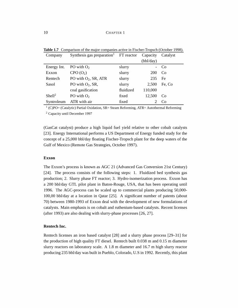
Table1.7 Comparisonof themajorcompaniesactive in Fischer-Tropsch(October1998).
Company Synthesisgaspreparation1 FT reactor Capacity Catalyst(bbl/day)
Energy Int. POwith O2 slurry - CoExxon CPO(O2) slurry 200 CoRentech POwith O2, SR,ATR slurry 235 FeSasol POwith O2, SR, slurry 2,500 Fe,Co
coalgasification fluidized 110,000Shell2 POwith O2 fixed 12,500 CoSyntroleum ATR with air fixed 2 Co1 (C)PO=(Catalytic)PartialOxidation,SR=SteamReforming,ATR= AutothermalReforming2 Capacityuntil December1997
(GasCatcatalyst)producea high liquid fuel yield relative to other cobalt catalysts[23]. Energy Internationalperformsa US Departmentof Energy fundedstudyfor theconceptof a 25,000bbl/dayfloatingFischer-Tropschplantfor thedeepwatersof theGulf of Mexico (RemoteGasStrategies,October1997).
Exxon
TheExxon’s processis known asAGC 21 (AdvancedGasConversion21stCentury)[24]. The processconsistsof the following steps: 1. Fluidized bed synthesisgasproduction;2. Slurry phaseFT reactor;3. Hydro-isomerizationprocess.Exxonhasa 200 bbl/dayGTL pilot plant in Baton-Rouge,USA, that hasbeenoperatinguntil1996. The AGC-processcanbe scaledup to commercialplantsproducing50,000-100,00bbl/dayat a location in Qatar[25]. A significantnumberof patents(about70) between1980-1993of Exxondealwith thedevelopmentof new formulationsofcatalysts.Main emphasisis on cobaltandruthenium-basedcatalysts.Recentlicenses(after1993)arealsodealingwith slurry-phaseprocesses[26, 27].
RentechInc.
Rentechlicensesan iron basedcatalyst[28] anda slurry phaseprocess[29–31] fortheproductionof high quality FT diesel.Rentechbuilt 0.038m and0.15m diameterslurry reactorson laboratoryscale.A 1.8 m diameterand16.7m high slurry reactorproducing235bbl/daywasbuilt in Pueblo,Colorado,U.Sin 1992.Recently, thisplant

INTRODUCTION 11
wasdismantledand transportedto Arunachal,India were it is expectedto produce350 bbl/dayof waxes in 1999 in cooperationwith the Indian company Donyi PoloPetrochemicalsLtd.
Sasol
SasolhasoperatedcommercialFischer-Tropschplantssince1955.A detailedreviewof Sasol’s commercialplantsfrom 1950to 1979is givenby Dry [32]. A commercialplant in Sasolburg (SouthAfrica) (Sasol1) usemultitubular (2050tubes,50 mm ID)fixed bedandentrainedbedKellogg reactors. Synthesisgasis predominantlypro-ducedwith Lurgi coalgasifiers.Sasol2 andSasol3 plantsin Secundawentonstreamin the beginning of the eighties. Theseplantsusecirculatingfluidized bedreactors(Synthol,Figure1.4c) for the productionof fuels andlow molecularweightolefins.Currently, Sasolhastwo new processesfor theFischer-Tropschsynthesis.A processat high temperatures(HTFT: 330-350 ˚C) for the productionof gasolineand lightolefinsanda processfor wax productionat lower temperatures(LTFT: 220-250˚C).TheHTFTisperformedin Syntholcirculatingfluidizedbed(CFB)reactors,but amoreefficientSasolAdvancedSynthol(SAS)reactorwith gas-solidfluidizationwasdevel-opedrecently[16]. The Syntholreactorswill be replacedby the new SAS reactors.Conventionally, ARGE tubular fixed bed reactorswereusedfor the LTFT process.In 1990,a slurry bubblecolumnreactor(SasolSlurry PhaseDistillate; SSPD)witha diameterof 1 m wascommissioned[15]. A commercial-scaleslurry reactoris inoperationsince1993andhasadiameterof 5 m andaheightof 22m with acapacityofabout2,500bbl/day. Table1.8showsanoverview of differentSasolreactors[15, 19].Furtherscaleupof theSSPDreactoris plannedto 20,000bbl/dayperreactor.
Table1.8 SasolFischer-Tropschcommercialreactors(bbl/day),adaptedfrom Jager[19].
CFB SAS ARGE SSPD
Total installedcapacity 110Q 000 11Q 000 3 Q 200 2 Q 500Capacityperreactor 6 Q 500 11Q 000 500-700 2 Q 500Potentialperreactor 7 Q 500 20Q 000 3 Q 000 20Q 000
Phillips Petroleum,Sasol,andQatarGeneralPetroleumCorp. signeda memo-randumof understandingto build a 20,000bbl/dayGTL plant at RasLaffan,Qatar.Thenew complex will useSasol’sSlurryPhaseDistillateProcess.Start-upis plannedfor 2002(RemoteGasStrategies,August1998).SasolandChevronannouncedplans(May 1998)to build a20,000bbl/dayGTL (Gas-To-Liquids)plantbasedontheSSPD

12 CHAPTER 1
technologyin Nigeria. Theestimatedcostpriceof this complex is $ 500-600million(RemoteGasStrategies,May 1998).Mostpatentsof Sasol(seeTable1.6)concernthedevelopmentof a slurry reactorwith continuousin-situ wax-solidseparation[33] andgrade-upof olefinsby hydroformulation[34].
Shell
In 1993,Shellstartedupa$ 850million FT synthesisplantin Bintulu, Malaysia.TheShellMiddle DistillateSynthesis(SMDS)process[5, 35] producesheavy paraffinsonacobaltcatalystin multitubular trickle bedreactors.Partof theseproductsaresoldaswax specialties;anotherpart is hydro-crackedover a noblemetalcatalystinto cleantransportationfuels(seeTable1.5). Theplantconverts100million cubic feet/dayofnaturalgasfrom off-shorefieldsby non-catalyticpartialoxidationinto 12,500bbl/dayhydrocarbons.The air separationplant of the SMDS plant in Bintulu explodedinDecember1997. Shell Oil wantsto reopenthe SMDS plant in 1999(RemoteGasStrategies,April 1998).MostShellpatentsfocusoneithercatalystdevelopmentor onthewaytheSMDSprocessis preferablycarriedout,for example,seepatents[36, 37].Somepatentsfor improving aslurryprocesshavebeenfiled aswell [38–40].
Statoil
Patentsof Statoilinvolveslurryreactordesignandcontinuouscatalyst-waxseparationswith theuseof filtration [41]. Recentpatentswith respectto Fischer-Tropschcatalysisconcernthedevelopmentof cobaltcatalystspromotedwith Rh,Pt,Ir, orReonalumina(for example,[42]). Statoil formed an alliancewith Sasolfor the developmentoffloatingFischer-Tropschplantsonshipsor floatingproductionsystems.Thesefloatingoff-shoreplantscanbeusedto utilize naturalgasassociatedwith oil production[43].
Syntroleum
Syntroleumis a small researchfirm in Tulsa,Oklahoma,USA, which hassignedli-censingagreementswith Texaco,ARCO,Kerr-McGee,andEnron.A laboratorypilotplant (2 bbl/day)is usedto demonstratetheir FT process.They claim that their pro-cesseliminatesa costlyair separationunit, sincetheir AutothermalReformer(ATR)producesnitrogen-dilutedsynthesisgasfrom naturalgas[44]. Nitrogencanbeusedtoremovesomeof thegeneratedheatduringtheFT reaction.TheSyntroleumprocessisthebasisof anagreementbetweenTexaco,Brown & RootandSyntroleumto develop

INTRODUCTION 13
a 2,500bbl/dayGTL plant,startingend1999(RemoteGasStrategies,January1998).Recently, SyntroleumandEnronannouncedfinal agreementto build a 8,000bbl/dayGTL plantin Wyoming,USA. Theplantis expectedto operatein 2001[45].
1.3 Research on the Fischer-TropschSynthesis
An optimaldesignwith respectto productyield andselectivity of a largescalereactorrequiresa deepunderstandingof hydrodynamics,reactionkinetics,catalyticsystemandFT chemistry(seeFigure1.5). Researchon thevariousaspectsof theFT processwill bediscussedbriefly. A detailedreview on kineticsandselectivity of theFischer-Tropschprocessis givenin Chapter2.
Kinetics, selectivityDeactivationCatalyst developmentR
Hydrodynamics, mixing,mass transferS , heat transfer,solids, bubble size,T design,
Uvapor-liquid equilibria
Mathematical Model
Commercial ReactorR synthesis gas
slurry
coolant
Pilot plant for verificationand scale upV
Figure1.5 Modelingof a largescaleFischer-Tropschreactor.
ReactionKinetics
The complexity of the FT reactionmechanismandthe large numberof speciesin-volved is the major problemfor developmentof reliablekinetic expressions.Mostcatalyststudiesaimat catalystimprovementandpostulateempiricalpower law kinet-ics for both thecarbonmonoxideconversionsandthecarbondioxide formationrate[46, 47]. Langmuir-Hinshelwood-Hougen-Watson(LHHW) type of rate equationshave beenappliedin literature(seeChapter2.8). The watergasshift reactioncanplay a dominantrole on iron catalysts.Only a few studiesreporton WGSkineticson
14 CHAPTER 1
iron catalystsunderFT conditions.A thoroughcomparisonof theavailableliteraturemodelsis presentedin Chapter2.
Product Selectivity
The productsfrom the Fischer-Tropschsynthesisform a complex multicomponentmixturewith substantialvariationin carbonnumberandproducttype. Main productsarelinearparaffins and O -olefins. Accordingto Anderson[48], theproductdistribu-tion of hydrocarbonscanbedescribedby theAnderson-Schulz-Flory(ASF)equation:mn WYX 1 Z[O]\^O n_ 1 with mn themole fractionof a hydrocarbonwith chainlengthn
andthe growth probability factor O independentof n. O determinesthe total carbonnumberdistribution of the FT products.The rangeof O dependson reactioncondi-tionsandcatalysttype. Dry [49] reportedtypical rangesof O on Ru, Co, andFeof:0.85-0.95,0.70-0.80,and0.50-0.70,respectively. More recentreferencesreportCocatalystswith chaingrowth factorsbetween0.85-0.95[5]. SignificantdeviationsfromtheASF distributionarereportedin literature:i) Relatively high yield of methane.ii)Relatively low yield of ethene. iii) Changein chaingrowth parameterO andexpo-nentialdecreaseof theolefin to paraffin ratio with increasingcarbonnumber. Thesedeviationsarepredominantlycausedby secondaryreactionsof O -olefins,which mayreadsorbon growth sitesof thecatalystsurfaceandcontinueto grow via propagationwith monomeror terminateashydrocarbonproduct.Detailson thecharacteristicsoftheproductselectivity andonmodelingof theselectivity arediscussedin Chapter2.
ReactorEngineeringModel
Mathematicalmodelingof FT slurry bubblecolumnswasreviewedby Saxenaet al.[17] andmorerecentlyby Saxena[50]. He showed that noneof the availablemod-els is accurateenoughfor a reliablereactordesign.Thebottleneckappearsto bethelack of reliablekinetic equationsfor all productsandreactantsbasedon realisticre-actionmechanisms.Until now, noneof theavailableliteraturemodelsobtainenoughdetailsto describethecompleteproductdistribution of theFischer-Tropschsynthesisat industrialconditions(high temperatureandpressure)asa functionof overall con-sumptionof synthesisgascomponentsandoperatingconditions. Either the productdistribution model (ASF behavior) or the kinetic scheme(no WGS andratesequa-tionswith first orderin hydrogen)is oversimplified,or thehydrodynamicsituationisunrealisticunderindustrial(churn-turbulentor heterogeneousflow regime)operatingconditions.Thefeaturesof themodelsavailablewill becomparedin Chapter7.

INTRODUCTION 15
1.4 Aims and Outline of this Thesis
The problemto be dealtwith in this thesisis the lack of accuratemodelsfor prod-uct distributionsandreactionkinetics,necessaryfor reliabledesignandscaleup ofindustrialFischer-Tropschprocesses.
Therefore,themajoraimof this thesisis thedevelopmentof aproductdistributionmodelanda kinetic modelboth in gas-slurryaswell asin gas-solidreactorsover acommercialprecipitatediron catalystbasedon own experimentalwork. Theproductdistribution modelshouldbeableto explain thedeviationsfrom theASF distributionobservedexperimentally. It shouldincludeamechanisticmodelof olefinreadsorptionandkineticsof chaingrowth and terminationon the samecatalyticsites. Accurateintrinsic rateexpressionsfor theCO conversionto Fischer-Tropschproductsandforthe watergasshift (WGS) reactionover a precipitatediron catalyston the basisofreliablemechanismsareanotheraim. A detailedmulticomponentmathematicalmodelfor a largescaleslurry bubblecolumnreactorwith useof our detailedmodelsis thefinal aimof this thesis.
Chapter2 presentsa literaturereview onthekineticsandselectivity of theFischer-Tropschsynthesis.Thefocusis on thereactionmechanismsandkineticmodelsof thewatergasshift andFischer-Tropschreactions.Literatureproductselectivity modelsarereviewedaswell. Heretheareaswhich requirefurtherresearchwill bedefined.
Chapter3 describesthe experimentalsetupof the kinetic experimentsboth in agas-solidandgas-slurrylaboratorykinetic reactorandthecatalystapplied.Theana-lytical sectionandtheexperimentalproceduresaredescribedaswell.
The developmentof a new O -Olefin ReadsorptionProductDistribution Model(ORPDM) basedon own experimentsfor the gas-solidFT synthesis,over a precip-itatediron catalystis presentedin Chapter4. Theeffectof variationof processcondi-tionson theselectivity is describedaswell.
Chapter5 presentsthekineticexperimentsandkineticmodelingof theCOhydro-genationandthewatergasshift reactionof gas-solidFischer-Tropschsynthesisovertheprecipitatediron catalyst.
The influenceof the slurry liquid on the productselectivity andthe reactionki-netics is presentedin Chapter6. The productselectivity model developedfor thegas-solidsystemwill be appliedfor the descriptionof the productselectivity at in-dustriallyrelevantconditionsover a precipitatediron catalystsuspendedin theslurryphase.Furthermore,Chapter6 describeskinetic modelingof thegas-slurryFischer-Tropschsynthesisbasedonamethodologyderivedin Chapter5.

16 CHAPTER 1
The modelsobtainedin Chapters4-6 and literaturedataon hydrodynamicsandmasstransferin theheterogeneousflow regimeareincorporatedin a multicomponentreactionengineeringmodel for a large scaleFischer-Tropschslurry bubblecolumnreactorin Chapter7. The main novel aspectof this modelis that, for the first time,multicomponentvapor-liquid equilibriawith detailedkinetic expressionsfor all reac-tantsandproducts(basedon original experimentalwork) arecombinedto predictthecompositionsof thegaseousandliquid streamsandtheperformanceof aslurrybubblecolumnreactor.
References
[1] Kroschwitz, I.; Howe-Grant,M., Kirk-Othmerencyclopediaof chemicaltech-
nology, Wiley & Sons,New York, fourthedn.1996.[2] Fischer, F.; Tropsch,H., Uber die Herstellungsynthetischerolgemische(Syn-
thol) durchAufbau ausKohlenoxydund Wasserstoff, Brennst.Chem.1923, 4,276–285.
[3] Fischer, F.; Tropsch,H., GermanPatent4843371925.[4] Jager, B.; Espinoza,R.,Advancesin low-temperatureFischer-Tropschsynthesis,
Catal.Today1995, 23, 17–28.[5] Sie,S.T., Processdevelopmentandscaleup: IV Casehistoryof thedevelopment
of aFischer-Tropschsynthesisprocess,Rev. Chem.Eng. 1998, 14, 109–157.[6] Choi, G.N.; Kramer, S.J.;Tam,S.T.; Fox, J.M., Design/economicsof a natural
gasbasedFischer-Tropschplant,in SpringNationalMeeting, AmericanInstituteof ChemicalEngineers,Houston,1996.
[7] Cybulski, A.; Edvinsson, R.; Irandoust, S.; Andersson,B., Liquid-phasemethanolsynthesis:modellingof a monolithic reactor, Chem.Eng. Sci. 1993,48, 3463–3478.
[8] Perry, R.H.; Green,D., Perry’s chemicalengineers‘ handbook, McGraw-Hill,New York, 6thedn.1984.
[9] Basini, L.; Piovesan,L., Reductionon synthesisgas costs by decreaseofsteam/carbonandoxygen/carbonratiosin the feedstock,Ind. Eng. Chem.Res.
1998, 37, 258–266.[10] Rentech,Gasto liquidshomepage,http://www.gastoliquids.com/tech2.htm(ac-
cessedDecember1998).[11] Rao,V.U.S.;Stiegel, G.J.;Cinquegrane,G.J.;Srivastave, R.D., Iron-basedcat-
INTRODUCTION 17
alystsfor slurry-phaseFischer-Tropschprocess:Technologyreview, Fuel Pro-
cess.Technol.1992, 30, 83–107.[12] Xu, L.; Bao,S.;R.J.,O’Brien; Raje,A.; Davis,B.H.,Don’t ruleoutironcatalysts
for Fischer-Tropschsynthesis,CHEMTECH1998, 8, 47–53.[13] Raje,A.P.; Davis,B.H.,Fischer-Tropschsynthesis:processconsiderationsbased
onperformanceof iron-basedcatalysts,Fuel1997, 76, 273–280.[14] Udovich, C.A., Ceramicmembranereactorsfor theconversionof naturalgasto
syngas,Stud.Surf. Sci.Catal.1998, 119, 417–422.[15] Jager, B., Developmentsin Fischer-Tropschtechnology, Stud.Surf. Sci.Catal.
1997, 107, 219–224.[16] Jager, B.; Dry, M.E.; Shingles,T.; Steynberg, A.P., Experiencewith a new type
of reactorfor Fischer-Tropschsynthesis,Catal.Lett.1990, 7, 293–302.[17] Saxena,S.C.;Rosen,M.; Smith,D.N.; Ruether, J.A.,Mathematicalmodelingof
Fischer-Tropschslurrybubblecolumnreactors,Chem.Eng. Commun.1986, 40,97–151.
[18] De Swart, J.W.A., Scale-upof a Fischer-Tropsch reactor, Ph.D.thesis,Univer-sity of Amsterdam,Amsterdam,TheNetherlands1996.
[19] Jager, B., Developmentsin Fischer-Tropschtechnology, Stud.Surf. Sci.Catal.
1998, 119, 25–34.[20] Choi, G.N.; Kramer, S.J.;Tam,S.T.; Fox, J.M.; Carr, N.L.; Wilson, G.R.,De-
sign/economicsof a once-throughnaturalgasbasedFischer-Tropschplantwithpowerco-production,in Coal liquefactionandsolid fuels, Pittsburgh,1997.
[21] Fox, III, J.M.,Thedifferentcatalyticroutesfor methanevalorization:anassess-mentof processesfor liquid fuels,Catal.Rev.-Sci.Eng. 1993, 35, 169–212.
[22] Gregor, J.H.,Fischer-Tropschproductsasliquid fuelsor chemicals.An econom-ical evaluation,Catal.Lett.1990, 7, 317–332.
[23] Singleton,A.H., Advancesmake gas-to-liquidsprocesscompetitive for remotelocations,Oil GasJ. 1997, 68–72.
[24] Eisenberg, B.; Fiato,R.A.; Mauldin, C.H.; Say, G.R.; Soled,S.L., Exxon’s ad-vancedgas-to-liquidstechnology, Stud.Surf. Sci.Catal.1998, 119, 943–948.
[25] Davis, B.H., Fischer-Tropschconversionof gasto liquid, Appl. Catal. A 1997,155, N4–N7.
[26] Behrmann,W.C.; Mauldin, C.H.; Pedrick, L.E., Patent WO 94147351994,Exxon.
[27] Koros,R.B.,USPatent53843361995, Exxon.[28] Benham,C.B.;Bohn,M.S.;Yakobson,D.L., USPatent55041181996, Rentech.

18 CHAPTER 1
[29] Benham,C.B.;Bohn,M.S.;Yakobson,D.L., USPatent56206701997, Rentech.[30] Benham,C.B.;Bohn,M.S.;Yakobson,D.L., USpatent56211551997, Rentech.[31] Benham,C.B.;Bohn,M.S.;Yakobson,D.L., USPatent55344371996, Rentech.[32] Dry, M.E., TheFischer-Tropschsynthesis,in J.R.Anderson;M. Boudart,eds.,
Catalysis-Scienceandtechnology, vol. 1, Springer-Verlag,New York, 1981pp.160–255.
[33] Inga,J.R.;Jager, B.; Kelfkens,R.C.;Malherbe,F.E.J.;Smith,M.A.; Steynberg,A.P., Eur. Patent609079,USpatent55998491994, Sasol.
[34] Betts,M.J. Dry, M.E.; Geertsema,A.; Rall, G.J.H.,PatentWO 97015211997,Sasol.
[35] Sie,S.T.; Senden,M.M.G.; VanWechum,H.M.H., Conversionof naturalgastotransportationfuels via the Shell Middle DestillateSynthesisprocess(SMDS),Catal.Today1991, 8, 371–394.
[36] Bode,D.; Sie,S.T., Eur. Patent1883041986, Shell.[37] Post,M.F.M.; Sie,S.T., Eur. Patent1672151984, Shell.[38] Engel,D.C.;VanderHoning,G.,PatentWO 97316931997, Shell.[39] Wijn, E.F.; Danckaarts,A.M., Eur. Patent6943251996, Shell.[40] McEwan,M.W.; Teekens,M.B., USPatent6943251978, Shell.[41] Lorentzen,G.B.;Myrstad,T.; Westvik,A., USPatent55208901995, Statoil.[42] Eri, S.;Goodwin,J.G.;Marcelin,G.; Riis, T., USPatent48015731989, Statoil.[43] Statoil,PressreleaseApril 14,1997.[44] Agee,K.L.; Willingham,F.Y., WO Patent97338471997, Syntroleum.[45] Syntroleum,PressreleaseFebruary24,1998.[46] Bub,G.;Baerns,M., Predictionof theperformanceof catalyticfixedbedreactors
for Fischer-Tropschsynthesis,Chem.Eng. Sci.1980, 35, 348–355.[47] Newsome,D.S., The water-gasshift reaction,Catal. Rev.-Sci.Eng. 1980, 21,
275–318.[48] Anderson,R.B., Catalystsfor the Fischer-Tropsch synthesis, vol. 4, Van Nos-
trandReinhold,New York 1956.[49] Dry, M.E., Catalytic aspectsof industrial Fischer-Tropschsynthesis,J. Mol.
Catal.1982, 17, 133–144.[50] Saxena, S.C., Bubble column reactorsand Fischer-Tropschsynthesis,Catal.
Rev.-Sci.Eng. 1995, 37, 227–309.