university of groningen the modelling of counter-rotating
TRANSCRIPT

University of Groningen
The modelling of counter-rotating twin screw extruders as reactors for single-componentreactionsGanzeveld, K.J.; Capel, J.E.; Wal, D.J. van der; Janssen, L.P.B.M.
Published in:Chemical Engineering Science
DOI:10.1016/0009-2509(93)E0023-6
IMPORTANT NOTE: You are advised to consult the publisher's version (publisher's PDF) if you wish to cite fromit. Please check the document version below.
Document VersionPublisher's PDF, also known as Version of record
Publication date:1994
Link to publication in University of Groningen/UMCG research database
Citation for published version (APA):Ganzeveld, K. J., Capel, J. E., Wal, D. J. V. D., & Janssen, L. P. B. M. (1994). The modelling of counter-rotating twin screw extruders as reactors for single-component reactions. Chemical Engineering Science,49(10). https://doi.org/10.1016/0009-2509(93)E0023-6
CopyrightOther than for strictly personal use, it is not permitted to download or to forward/distribute the text or part of it without the consent of theauthor(s) and/or copyright holder(s), unless the work is under an open content license (like Creative Commons).
The publication may also be distributed here under the terms of Article 25fa of the Dutch Copyright Act, indicated by the “Taverne” license.More information can be found on the University of Groningen website: https://www.rug.nl/library/open-access/self-archiving-pure/taverne-amendment.
Take-down policyIf you believe that this document breaches copyright please contact us providing details, and we will remove access to the work immediatelyand investigate your claim.
Downloaded from the University of Groningen/UMCG research database (Pure): http://www.rug.nl/research/portal. For technical reasons thenumber of authors shown on this cover page is limited to 10 maximum.

Pergamon Chemical En@neering Science, Vol. 49. No. IO, pp. 1639-1649, 1994 Copyright Q 1996 Ekvicr Sciena Ltd
Printed in Great Britain. All ri$ls msevtd ON%250!+94 S6.M + 0.00
0009-2509(93)EQO23-6
THE MODELLING OF COUNTER-ROTATING TWIN SCREW EXTRUDERS AS REACTORS FOR SINGLE-COMPONENT
REACTIONS
K. J. GANZEVELD, J. E. CAPEL, D. J. VAN DER WAL and L. P. B. M. JANSSEN’ Department of Chemical Engineering, Groningen University, Groningen, The Netherlands
(First received 8 September 1992; nccepredfor publication in reuisedform 9 November 1993)
Abstract-Numerical models are useful to study the behaviour of the extruder as a polymerization reactor. With a correct numerical model a theoretical analysis of the influence of several reaction and extruder parameters can be made, the limitations of the use of the extruder reactor can be determined and the effects of scale-up can be studied. The numerical model developed for a single-component reaction in a twin screw extruder shows good agreement with experimental data for the polymerization of n-butylmethacrylate durine the reactive extrusion orocess. At low rotation rates a disaereement mav occur between exneriments and predicted data. Howeve;, the program is very operate in the area of high rotational speeds.
useful for inldustrial scak processes where kxtruders
INTRODUCTION
Models for reactive extrusion are important to study the effect of operating conditions and geometric para- meters on the progress of the reaction. With accurate numerical models, predictions can be made about the extruder behaviour, scale-up effects of the process can be studied in detail and expensive experiments can, to some extent, be omitted. Numerical modelling there- fore plays an important role in the study of the ex- truder as a reactor (Stuber and Tirrel, 1985; Speur et al., 1987 and Speur, 1988). Both authors, mentioned above, tried to model the extsuder reactor leading to two similar models, based on the ideal mixed reactor approximation. Major imperfections of these models are the use of kinetic and extruder constants in the model which were determined by trial and error, or by using data and relations not applicable to the reaction studied. Therefore, the model results have no physical basis and cannot predict the ongoing process in the extruder.
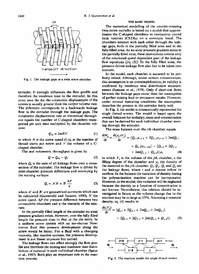
transported towards the die. Interaction between the chambers occurs through the leakage gaps (Fig. 1). The leakage gaps are divided into four groups (Janssen, 1978):
.-the flight gap (Q,). This is a clearance between the barrel and the flight of the screws.
-the tetrahedron gap (QI). Between the flight walls a gap exists having approximately the shape of a tetrahedron. This gap connects the consecutive chambers on the opposite screws.
~ the calender gap (Qd. This gap is formed by the clearance between the flight of one screw and the bottom of the channel of the other screw and resembles a calender.
~ the side gap (Q.). This is a gap between the flanks of the flights of the two screws.
In this paper an extended and improved numerical model of the extruder reactor for a one-component reaction is presented and discussed, using parameter values which have, as far as possible, a physical mean- ing. The obtained model is validated by compa;lng model results with experimentally obtained data for the poiymerization of n-butylmethacrylate.
Often, a monomer or pre-polymer is fed in liquid form to the extruder reactor. Due to this liquid feed two zones can be distinguished:
-A partially filled zone where the chambers are still not completely filled with material.
-The pump zone, completely filled with material where pressure is built up and where the material is transported towards the die,
THE WORKING MECHANISM OF A COUNTER-ROTATING TWIN SCREW EXTRUDER
A counter-rotating twin screw extruder, as used in this work, is closely intermeshing and consists of series of C-shaped chambers in which material is
The position of the reaction zone in the extruder is dependent on temperature, throughout and the rota- tion speed of the screws. These parameters also deter- mine the starting point of the reaction, especially the temperature has a large influence. The influence of the other parameters on the position of the reaction zone are marginal. Under normal operation the reaction starts in the partially filled zone.
+Author to whom correspondence should be addressed. The fully filled zone or the pump zone is an im-
portant feature in the working of the twin screw
1639
1640 K. J. GANZEVELD et 01.
transport direction
1
Fig. 1. The leakage gaps in a twin screw extruder.
extruder. It strongly influences the flow profile and therefore the residence time in the extruder. In this zone, near the die, the volumetric displacement of the screws is usually greater than the output volume rate. The difference corresponds to a backwards leakage flow in the extruder through the leakage gaps. The volumetric displacement rate or theoretical through- out equals the number of C-shaped chambers trans- ported per unit time multiplied by the chamber vol- ume:
Qlh = 2mNV (1)
in which N is the screw speed (l/s), m the number of thread starts per screw and V the volume of a C- shaped chamber.
The real volumetric throughput is given by
Q = Q,I, - Ql (2)
where Qr is the sum of all leakage flows over a cross- section of the extruder. The leakage flow is driven by inter-chamber pressure differences and conveying by the moving surfaces:
Qr = A’N + B’ y (3)
where A’ and B’ are geometrical constants which can be calculated (Ganzeveld and Janssen, 1990), N the screw speed, AP the pressure difference between two consecutive chambers and rl the viscosity of the mix- ture.
In the partially filled length of the extruder no axial pressure gradient exists. However, over the fully filled length the pressure rises to that at the die entry. In a uniform screw system with an iso-viscous New- tonian fluid this pressure development along the screw would be linear. For a fluid with a changing viscosity, like reactive systems, the pressure develop ment is not linear anymore but curved.
The leakage flows can affect strongly the flow pro- file and therefore the mixing and residence time distri- bution of material in each individual chamber (Speur et al., 1987). Both play an important role in the reac- tion process.
THE BASIC MODEL
The numerical modelling of the counter-rotating twin screw extruder is based on a model that approx- imates the C-shaped chambers as continuous stirred tank reactors (CSTRs) on a conveyor band. The chambers interact with each other through the leak- age gaps, both in the partially filled zone and in the fully filled zone. As no axial pressure gradient exists in the partially filled zone, these interactions consist only of the rotational speed dependent part of the leakage Row equations [eq. (3)]. In the fully filled zone, the pressure driven leakage flow also has to be taken into account.
In the model, each chamber is assumed to be per- fectly mixed. Although, under certain circumstances, this assumption is an oversimplification, its validity is confirmed by residence time distribution measure- ments (Janssen et al., 1979). Only if short-cut flows between the leakage gaps occur does the assumption of perfect mixing lead to erroneous results. However, under normal operating conditions the assumption describes the process in the extruder fairly well.
In Fig. 2, the model is schematically represented for single thread screws. The model is based upon the overall balances for enthalpy, mass and concentration that can be derived for each individual chamber mov- ing through the extruder.
The mass balance over the jth chamber equals
dMj d(PjsVj) dt -- = {Q~,~P,+I + 2Q,,tpj+z + 2m(Q,,i dt
+ Qs.dPj+zm} - (Qt.0 + 2Q,o
+ 2dQc.e + Qs,o)}Pj (4)
in which Vi is the volume of the jth chamber, E the filling degree of the chamber and p, the density of the material in the jth chamber. Q,, Q,, Q, and Q, are the leakage flows, where i and o denote inflow or outflow. In the balance the variation of density during the polymerization reaction can be incorporated. However, in the model, this variation will be neglected because the density as a function of concentration is not known. Nevertheless, this relation should be in- vestigated in future as the volume change due to the reaction may be as large as 15%. Assuming a constant density, eq. (4) results in
y = {Qg, i + 2Q/, i + 2mQ,. i -t 2mQ,, i)
- {Qt.. + 2Qr.0 + 2mIQe.0 + Qs.0)). (5)
j-a j- 1 j+1 a a -
j-2 i
Fig. 2. The reaction model for single thread screws.

Reactors for single-component reactions 1641
Except at the transition between the partially filled and fully filled zone, no accumulation of material will occur in the chamber, for screw sections with a con- stant chamber volume. The ingoing flow should there- fore be equal to the outgoing flow. The achievement of this steady state may be problematic as the pumping action of the twin screw extruder is poor for liquids with a low viscosity. However, during the experiments no serious problems were encountered.
The second relevant balance for the model is the monomer concentration balance which equals
l’jtz = - sl’,/IR + {Qg,iCj+l + 2(Q,.iCj+l)
+ 2mtQc.t + Qa.i)Cj+zmI - {Qr,o + 2Qf.v + WQc.0 + Qs..,>c, C-9
where R is the reaction rate and Cj the concentration of monomer in the jth chamber.
The energy balance is coupled to the monomer concentration balance by the reaction term, as this depends on the monomer concentration and the tem- perature. The energy balance eouals
+ 2(Q,;Tj+,) + 2m(Q,,i + Qa.i)Tj+Zm}
- (Q1.o + 2Q/.o + WQc.0 + Qs.o)>rjl + hA(Tw - Tj) (7)
where cP is the specific heat, AH, the reaction en- thalpy, Tj the temperature in the chamber observed, h the heat transfer coefficient, A the heat exchanging surface of the chamber and T, the temperature of the wall at the position of the chamber.
The model is based on the changes in a single chamber moving through the extruder. Therefore, the coordinate system is attached to the moving chamber and not to the extruder.
The relation between the time and the position of the chamber in the extruder is determined by the displacement velocity of the chamber through the extruder. This velocity (u,) equals the product of the rotational speed of the screws (N) and the pitch of the screw at the position of the chamber [S(x)]:
u, = NS(x). (8)
The position of the chamber in the extruder equals
x(t) = N f
*S(x)dt. 0
(9)
For a screw with a constant pitch, this results in
x(t) = NSt. (IO)
Additionally, equations for the fully filled length, the heat transfer and the kinetics are necessary to com- plete the description of the model. The fully filled length is determined by the die pressure, the viscosity profile of the reactive material and the leakage flows.
The die pressure is an input parameter of the model. The viscosity profile can be calculated by a viscosity model. The heat transfer coefficient can be calculated from different theories, of which the coefficient de- rived by Speur (1988) gives the most accurate results (see the heat transfer description). The reaction kin- etics used here describe a first-order bulk poly- merizaton with a superposition of the gel effect (as will be explained later).
Solving the total set of equations numerically for a chosen bulk polymerization leads to profiles for the conversion, molecular weight, temperature and pres- sure, from which the progress of the reaction in the extruder can be studied.
One extra complication occurs, when validating the model with experimental results, if the reaction is not completed at the end of the extruder. The reactive mixture will also react in the die. For large dies in particular, this may have a notable effect on the final product. Because of the complex geometry of a good extruder die and the shear and elongational effects, it is very complicated to model the reaction process in the die. Nevertheless, to form an impression of the ongoing reaction, the die is approximated as a simple tube with a certain volume in which the material is transported as plug flow. The residence time in the mode1 die equals the residence time in the experi- mental die.
THE RHEOLOGICAL MODEL
Understanding the rheological properties of poly- mer-monomer solutions is essential for modelling bulk polymerizations. In reactive extrusion, the hy- drodynamic behaviour of the extruder is strongly in- fluenced by the rheological properties. Therefore, to be able to mode1 the extruder as a reactor and to calculate the fully filled length, the viscosity profile of the reactive mixture has to be known.
Stuber (1986) developed an empirical model which accurately describes this viscosity behaviour of the radical bulk polymerization over the whole concen- tration range. The mode1 is based on known empirical behaviour of polymer solutions. The basis of the model is
in which
qo(C, A,, T) = F5
F = KC1 + u~(c~,)~~~ + ~~(cti,J]~.~ (11)
and
C=exp[(h,+h,c+h,c’)(i-$--)+b,c’]
where c is the polymer concentration in weight per- cent, I@,,, the weight average molecular weight of the polymer in thousands, K, n,, a2, b,, b,, b, and b, are constants and T and Trcf are temperatures in K. The parameter T,=r adjusts the concentration dependence of the viscosity model at low concentrations. As

1642 K. J. GANZEVELD et al.
Trsr decreases, the concentration dependence for low concentrations decreases.
The equation was used to predict accurately the solution viscosity data for the polymerization of methylmethacrylate (MMA). By adjusting the con- stants, the viscosity model can also be used for other polymerization reactions.
In our case, the bulk polymerization reaction in- vestigated in the extruder is the polymerization of butylmethacrylate (BMA). For this reaction, no useful rheological data exist which could be applied to the model in order to adjust the constants. However, the behaviour of the BMA/PBMA solution can be ex- pected to be very similar to the MMAJPMMA solu- tion, due to the similarity in their molecular structure (Lachinov et al., 1978; Pezzin, 1966). Therefore, the viscosity mode1 for MMA/PMMA should predict the rheological behaviour of the BMA/PBMA solution fairly accurately.
Only the absolute viscosities of the BMA/PBMA mixture have to be adjusted due to the larger mobility of the molecules which decreases the viscosity and decreases the concentration dependence at low con- centration of the polymer. This is done by adjustment of the reference temperature in the model presented by Stuber from 465.15 to 400.15 K. The remainder of the values used for the rheological model of the BMAjPBMA mixture are equal to the values used by Stuber for the MMAJPMMA solution. Model results were compared with the little data available (Yemelyanov et al., 1982) and appeared to agree reas- onably well. The values of the constants for the BMA/PBMA solution are given in Table 1.
The rheological model obtained is used to predict the viscosity profile in the extruder under different reaction circumstances and to determine the fully filled length of the extruder.
The model does not take the influence of shear rate on the viscosity into account. For the reaction used the dependence of the viscosity of the polymer-mono- mer mixture on shear is already small. Although the changes of viscosity in the leakage gaps due to non- Newtonian effects can influence the pressure built up, and therewith the fully filled length, the viscosity
Table 1. Values of constants used in the rheological model
K 0.00216 bo 600 (11 0.125 b, 80 a, 3.75 x lo-” b2 1 T rsf 400.15 b3 1.2x 10-S
initiation:
changes associated with the progress of the reaction and changing temperature are far more superior.
THE HEAT TRANSFER MODEL
During the bulk polymerization reactions in the extruder, a large amount of heat is released, Heat transfer is therefore an important process parameter. Several heat transfer models exist based on the pen- etration theory, almost all in the area of single screw extruders (Jepson, 1953; Mohr et al., 1957; Janeschitz- Kriegl and Schijf, 1969; Janssen et al., 1975).
Speur (1988) derived an empirical model for the heat transfer coefficient in a counter-rotating twin screw extruder which was used in the modelling. The heat transfer coefficient was determined from the en- ergy balance for a single C-shaped chamber interac- ting with its neighbours:
This heat transfer coefficient is dependent upon the rotational speed and the relative throughput of the extruder (a,):
h = 410 & (. >
1.65 - 2.36E. (12)
It is particularly significant that for all experiments the value of this heat transfer coefficient exceeds the value of the heat transfer coefficient as calculated by penetration theory. This may be attributed to an additiona convective effect associated with the flow pattern in the chamber. Also the heat transfer through the flights of the screw, which is neglected ‘in the penetration theory, may have a positive effect on the total heat transfer.
THE KINETIC MODEL
Bulk polymerizations of acrylates are free radical addition polymerizations. With this type of reaction, polymer chains are formed in a relatively short time and subsequently excluded from further participation in the reaction process. The chain formation can be divided into three steps:
-initiation or chain start -propagation or chain growth -termination or chain stop.
With these types of reactions, the velocity of the termination step varies during the polymerization, leading to the occurrence of the so-called Trommsdorff or gel effect which causes an abrupt increase of the propagation velocity.
The progress of the BMA polymerization looks as follows:
CH3 CH3
R=+ CH,=C ki RCH,-C I I
COOC4H9 COOC,H,

Reactors for single-component reactions
propagation:
1643
CHs I
+ CH,=C I
COOC+H!, COOC~HQ
termination:
CH3 I
CH2-C l +R I
i COOC4H9
/ 1 CH” CH3 CH3 / CH3 \
R
in which ki, k,, k,, and ktd are, respectively, the reac- tion constants for the initiation reaction, the propaga- tion reaction, the termination by combination and the termination by disproportionation.
Due to the appearance of the aforementioned gel effect at a certain instance during the reaction, the reaction progresses in two stages:
-The first stage, the beginning of the reaction, can be described by the conventional kinetics also used for diluted polymer systems. In this stage, the polymerization of butylmethacrylate is a first-order reaction in the monomer concentra- tion.
-The second stage in the reaction progress is reached when the conversion has increased to a certain point. The reaction mixture has be- come more and more viscous, leading to a lim- itation in the mobility of the polymer chains.
The termination reactions are now controlled by dif- fusion limitation, resulting in a reduced termination reaction constant k, (TrommsdorfI et al., 1947; Cardenas and O’Driscoll, 1976). Due to the reduced k, the amount of polymer radicals increases, resulting in an abrupt increase of the propagation velocity, called the gel effect or Trommsdorff-effect. The appearance of the gel effect leads to a higher conversion and
a drastic increase of the average molecular weight of the polymer formed. No simple equations for the reaction velocity at this stage of the polymerization exist. However, the second stage does play an impor- tant role in the reactive extrusion process.
To be able to simulate the bulk polymerizations, Marten and Hamielec (1979) have proposed a semi- empirical model which includes the gel effect. The model is based on the free-volume theory for which two problems have to be solved:
(1) Determination of the conversion at which sig- nificant chain entanglements first occur.
(2) Development of a relationship which gives the decrease in the terminatian rate constant as a function of temperature and polymer weight and concentration.
The solution of the problems leads to the following relation for the termination constant k,:
$= (krexp[ --A(+&)] (13)
where k,, is the initial termination rate constant, Mwsrr is the critical weight average molecular weight at the conversion where the gel effect starts, a, is the weight average molecular weight, LJ is a constant

1644 IL J. GANZEVELD et crl.
which value depends on the stage of the polymer- ization, A is a constant, V, is the free volume and V FEI 1 is the critical free volume at the onset of the gel effect.
The free volume can be calculated from
F’r = CO.025 + a,(T - T,,)] F + (0.025 T
+ K,(T- T&p (14) r
where the indices p and m denote polymer and mono- mer and c( = c(r - Q, K, is the expansion coefficient for the liquid state, a, the expansion coefficient for the glassy state, T, the glass transition temperature, V the volume and V, is the total volume.
The critical free volume is determined by
KS = ML1 exp (A/V,& (15)
Kg is a constant which is dependent upon temper- ature and determined empirically, m is arbitrarily set equal to 0.5 and A is a constant.
The combination of the equations leads, for a bulk polymerization above the glass transition temper- ature, to a general rate expression:
2 = k, ‘; 0 o.5 (1 - x) (1 VI:.’ =P( - ki@)
x($&-).ev(g(k- &)) (16)
where kd is the reaction constant for the decomposi- tion of the initiator, f the efficiency factor of the initiator, k,, is the initial termination constant, x the degree of conversion, .s the volume contraction factor (d, - d,,,)/d,, d, is the density of the polymer, d, is the density of the monomer, [1], is the initial initiator concentration and t is the time.
For the first stage of the polymerization, the con- stants a and A have to be zero as no gel effect is present. However, as the termination reaction be- comes diffusion limited and the gel effect starts to occur, values for a and A have to be determined. Both values are estimated using a fit to some of the experi- mental data.
Finally, the development of the molecular weight as a function of the conversion has to be known. Marten and Hamielec state this relation to be
2Mu “dx cum&%,=- -
x s D r (17)
where Mu is the molecular weight of the monomer and r the reciprocal instantaneous number average degree of polymerization.
By solving eqs (16) and (17) simultaneously, the conversion-time history can be obtained. However, due to the already complicated reaction situation in the extruder, the simultaneous solving of these bal- ances is not practicable. Also, the agreement between the experimentally measured R, and the It-i, cal- culated by the Marten and Hamielec model is rather
poor. Therefore, a new expression for the relation between the instantaneous weight average molecular weight and the conversion [eq. (17)] has to be found.
This expression can be found by looking at the outcomes of the experiments of the polymerization of MMA and BMA. It shows that in the gel effect area the relation between the molecular weight and the conversion can almost be assumed to be a straight line (Ganzeveld, 1992; Marten and Hamielec, 1979). This is, of course, an oversimplification of the relation but very useful for the modelling of the extruder as will be established later. Based on this experimental data, eq. (17) is now assumed to be equal to
I\;i, = 78 1. conversion - 6500 (18)
where the conversion is in weight percentage. With eqs (16) and (18), the reaction kinetics can
now be solved for reactive extrusion. The constants and parameters used in these equations are a combi- nation of the data used by Marten and Hamielec for MMA polymerization and data available on the BMA polymerization and components. The first are used as a substitute for lacking BMA data. As MMA and BMA are similar in chemical stucture, this substi- tution should still result in reliable reaction data. Therefore, the constants A, K3, VFcfl and Tg,,, are data of Marten and Hamielec. r,,, a,, u,, Mucrl and E are literature data on BMA and PBMA (Brandrup and Immergut, 1989; Pezzin, 1966). The constant a is ad- justed on the basis of our own experimental data on the polymerization of BMA in the extruder. The con- stants used are presented in Table 2.
COMPARISON BETWEEN THE SINGLE-COMPONENT REACTION MODEL AND THE EXPERIMENTS
By comparing the model with experimental results and analysis of the validity of the assumptions and omissions in the numerical program can be per- formed. It also gives an insight into the consequences of simplifications which are present in a numerical model.
Experimental set-up A mixture of n-butylmethacrylate (inhibited), with
a combination of a fast initiator and a slow initiator was fed to the extruder, at room temperature. The fast initiator assumes a start of the reaction at relatively low temperatures and therefore decreases the max- imum temperature in the extruder, whereas the slow initiator is still active towards the end of the process, when temperatures are high. The mixture and the
Table 2. Values of constants used for the kinetic model of BMA
A I.1 1 %I 1 x 10⁻³ a 0.0 1 a. 5 x10⁻⁴ & 2.7 X 10⁵ J,,,, 30,ooo T v 167 K VF,,, 0.151 T BP 293 K E 0.154

Reactors for single-component reactions 1645
extruder were both flushed with nitrogen to prevent an extra inhibition of the reaction.
The mixture was extruded in a 40 mm Rollepaal counter-rotating twin screw extruder (L/D = 15). The extruder has five heating zones with which a temper- ature profile over the extruder can be established. The basic settings of the extruder are
concentration slow initiator 1.2% concentration fast initiator 0.5% screw speed 0.63 l/s die pressure OPa throughput 26.2 gjmin inlet temperature 20°C wall temperatures 20,120, 130, 130,
120°C die temperature 110°C.
The different parameters were varied one at a time while the other parameters remained those of the basic setting. The pressure profile over the extruder was measured with three pressure transducers. The output of the extruder ranged from 1.2 to 2.9 kg/h. The samples collected for the different reaction cir- cumstances were directly frozen in liquid nitrogen to stop the reaction immediately. The samples were ana- lyzed for conversion and number and weight average molecular weight. The conversion of the polymer- ization reaction was determined gravimetrically. The molecular weight of the samples is determined by gel permeation chromatography.
The comparison A direct comparison between the experiments and
the simulations showed a good agreement for almost all parameters (Figs 3-S). In most circumstances, both the experimentally determined conversions and the molecular weights agree reasonably well with the cal- culated results. The minor deviations may be at- tributed to the use of simplifications in the rheological and kinetic model.
However, a large disagreement is visible when the results of the simulation of the progress of the reaction at increasing screw speed with no fully filled length
a0 25 30 35 40 45 50
thrcugtwut (g/m(n)
+ ExDerlments - Model
Fig. 3. A comparison between the experimentally and nu- merically obtained conversions for an increasing throughput
(N = 0.63 l/s and Pdis = 0 bar).
FE 25 30 35 40 45 50
P thrcu&xt (g/min)
l Experiments - Model
Fig. 4. The comparison of the molecular weights ob- tained for an increasing throughput (N = 0.63 I/s and
Pdic = 0 bar).
100 (
+ EW. - Model 0 EXP. -- Model 1 1 2 2
Fig. 5. The conversion as a function of the die pressure fhr the experimental and numerical data (N = 0.63 l/s). Situa-
tion 1: Q = 20.3 g/min, situation 2: Q = 31.0 g/min.
a c
4 70
+ +
+
Fig. 6. The molecular weight as a function of the die pressure for model and experiments (Q = 20.3 g/min, N = 0.63 l/s).
present are compared with the experiments (Fig. 9). Where the experiments show an independence of the rotation rate of the screws, the model shows a de- crease. Also, the calculated conversions at low rota- tion rates are much higher than observed during the

1646 K. I. GANZEVELD et at.
40 ’ 0 9 10 15 20 25
rul-ber of fully fllkd charrbers w
+ Exp. - Model 0 Exp. -- Model 1 1 2 2
Fig. 7. A comparison between the predicted and modelled influence of the fully filled length on the conversion of the reaction (14 = 0.63 I/s) situation 1: Q = 20.3 and 2:
Q = 31 .O g/min.
number of fully fllled chambers (-)
+ Experiments - Mode
Fig. 8. A comparison between the predicted and modelled influence of the fully filled length on the molecular weight of
the reaction (Q = 20.3 g/min and N = 0.63 I/s).
80
2 s M .- t 40 s
20
0 I + *Y-Y-h--
0.00 0.4s 0.36 0.54 0.72 0.90
rotation soeed of the screws (l/d
+ Expwiments --I
Fig. 9. The influence of the rotation rate of the serewswn the conversion; a comparison between the model and the experi-
ments (Q = 26.2 g/min and Pdic = 0 bar).
experiments. This is probably due to a lower material temperature caused by the formation of a polymer barrier at the barrel wall at low rotation rates of the screws. It results in a lower overall reaction constant.
leading to the lower conversions observed. However, this explanation is not experimentally verified.
Nevertheless, if a fully filled length is present or the rotational speed is high, as both is the case in indus- trial processes, the result of the model agree well with the experiments (Fig. 9).
MODEL PREDICTIONS
Next to a direct comparison of the model results and the experimental data obtained, the model can also be used to predict the progress of the reaction in the extruder. To investigate the influence of extruder and reaction parameters on the reaction process, sev- eral situations are simulated.
One of the limitations for the use of an extruder as a reactor is the reaction enthalpy. Therefore, it is interesting to study the effect of a significant rise in the heat of reaction on the temperature profile in the extruder. For both simulations it is assumed that the reaction kinetics are equal to the kinetics of BMA. The extruder settings are:
~ rotational speed: 0.50 l/s ~ throughput: 0.60 g/s - walJ and die temperatures: 120, 130, 130, 120,
110°C ~ die pressure: 0 bar.
Figure 10(a) and (b) show the progress of the reaction
CW ~ % -- temp. - wall
terrp.
Fig. 10. The influence of the reaction enthalpy on the reaction progress (Q = 37.6 g/min, N = 0.50 I/s and P,,, = 0 bar): (a) AH, = 56.5 kJ/mol, (b) AH, = 180 kJ/
mol.

Reactors for single-component reactions 1647
in the extruder for two different reaction enthalpies. It is apparent that the reaction enthalpy not only has an influence on the maximum temperature reached in the extruder but that the conversion is also clearly affected. At a reaction enthalpy of 56.5 kJ/mol (BMA), the temperature hardly deviates from the wall temper- ature and the maximal conversion is only 80%. A re- action enthalpy of 180kJ/mol, on the other hand, causes a drastic increase in the maximum temperature of the material in the extruder, whereas a 100% con- version is already reached after l/6 of the length of the extruder. The sharp increase in the mixture temper- ature was not present in simulations with a reaction enthalpy below 160 kJjmo1. Only moderate temper- ature increases of 30°C are reached for these situ- ations, which are often acceptable for production pro- cesses. Nevertheless, reactions with a reaction en- thalpy in the order of 150 kJ/mol, and with reaction kinetics similar to the butylmethacrylate polymer- ization, should be processed with caution in the type and size of the extruder used for the simulation. This conclusion is, of course, valid within the limitations of the simulation program.
Another parameter which can cause a too high material temperature in the reactor are the wall and die temperatures. An increase of the wall temperature in the first part of the extruder causes the reaction front to move towards the feed end as the reaction components reach the reaction temperature earlier. This results in a longer reaction time in the extruder and therefore a higher conversion of the reaction and a possible higher temperature of the product. A de- crease of the wall temperature in this part causes the opposite effect, namely, the shift of the reaction front towards the die leading to shorter effective residence times, lower conversions and lower material temper- atures. Two wall temperature profiles are simulated, the results of which are presented in Fig. 11.
From the simulations it can be concluded that the conversion is significantly influenced by a change in the temperature profile. However, the maximum tem-
? ‘- 100 ___-------__+ ‘60 1
0 100 200 300 400 s&T
Posltlcm lrl the extruder lrrld
- % -~ % -Tw---TV, 1 2 1 2
Fig. 11. The effect of the temperature profile on the reaction, (Q = 20.3 g/min and Pdic = 0 bar). Situation 1: temperature profile 120, 130, 130 and 120°C. situation 2: temperature
profile 140, 150,150 and 150°C.
perature the mixture reaches in the extruder is hardly affected by a change in the wall temperature, unlike the effect of a change in the reaction enthalpy.
The moving of the reaction front can also be caused by the rotational speed. The rotational speed influ- ences the position of the reaction zone in the extruder. A high rotational speed causes the reaction front to move towards the die. This indicates that if the screw speed is too high the situation could occur in which the reaction does not take place in the extruder at all. However, a higher rotational speed results in a larger theoretical throughput thereby also permitting a higher throughput. As the movement of the reaction front now limits the rotational speed which can be used, the throughput for the process also becomes limited, thus restricting the working area.
The boundaries of the restricted working area are very important, especially for industry. However, simulations show that if a fully filled length is present in the extruder, the effect of the rotational speed on the reaction process is marginal.
Only if the die pressure is zero, a non-desirable situation in most processes, does the rotational speed have a considerable influence on the reaction progress (Fig. 12).
The die pressure has a major influence on the reac- tion process. The residence time is largely dependent on the fully filled length and, consequently, on the die pressure. Therefore, the conversion of the reaction is, to a large degree, determined by the die pressure. This is visualized in Fig. 13.
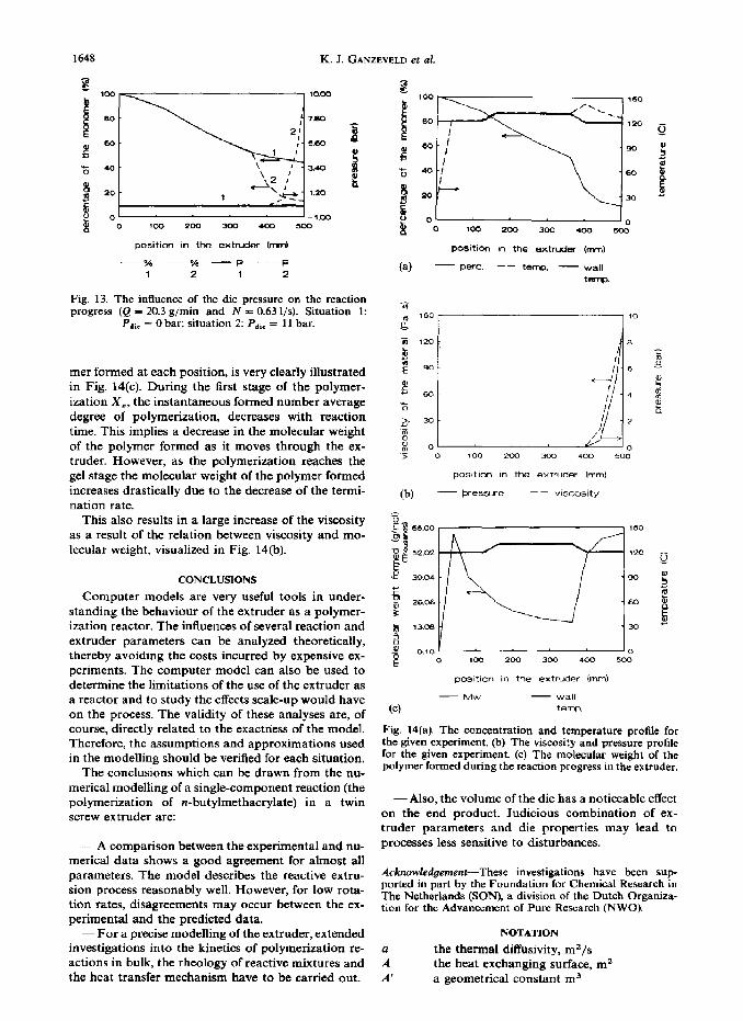
A complete simulation for a single experiment is shown in Fig. 14(aHc). The extruder settings are:
-rotational speed: 0.63 I/s -throughput: 0.34 g/s -wall and die temperatures: 120, 130, 134 120,
llO”C -die pressure: 11 bar.
The influence of the gel effect on the reaction pro- gress, specifically on the molecular weight of the poly-
poslticm in the extrudef hnl
-.- % -- 46 - Wall
1 2 tenp.
Fig. 12. The dependence of the reaction progress on the rotation rate (Q = 26.3 g/min and Pdir = 0). Situation 1:
N = 0.63 I/s; situation 2: N = 0.18 I/s.
1648 K. J. GANZEVELD et ~1.
position in the extruder kmd
- 0% -- o/6 --p _--p
1 2 1 2
Fig. 13. The influence of the die pressure on the reaction progress (Q = 20.3 g/min and N = 0.63 I/s). Situation 1:
Pdic = 0 bar; situation 2: Pdlr = 11 bar.
mer formed at each position, is very clearly illustrated in Fig. 14(c). During the first stage of the polymer- ization x,, the instantaneous formed number average degree of polymerization, decreases with reaction time. This implies a decrease in the molecular weight of the polymer formed as it moves through the ex- truder. However, as the polymerization reaches the gel stage the molecular weight of the polymer formed increases drastically due to the decrease of the termi- nation rate.
This also results in a large increase of the viscosity as a result of the relation between viscosity and mo- lecular weight, visualized in Fig. 14(b).
CONCLUSIONS
Computer models are very useful tools in under- standing the behaviour of the extruder as a polymer- ization reactor. The influences of several reaction and extruder parameters can be analyzed theoretically, thereby avoiding the costs incurred by expensive ex- periments. The computer model can also be used to determine the limitations of the use of the extruder as a reactor and to study the effects scale-up would have on the process. The validity of these analyses are, of course, directly related to the exactness of the model. Therefore, the assumptions and approximations used in the modelling should be verified for each situation.
The conclusions which can be drawn from the nu- merical modelling of a single-component reaction (the polymerization of n-butylmethacrylate) in a twin screw ex truder are:
-A comparison between the experimental and nu- merical data shows a good agreement for almost all parameters. The model describes the reactive extru- sion process reasonably well. However, for low rota- tion rates, disagreements may occur between the ex- perimental and the predicted data.
~ For a precise modelling of the extruder, extended investigations into the kinetics of polymerization re- actions in bulk, the rheology of reactive mixtures and the heat transfer mechanism have to be carried out.
(4
POtitlOn m the extruder (n-m)
- pert. -- temp. - wall t@Kw.
09
posdtian fn the extruder (mm)
- eressure ~ ~ viscosity
65.00 150
52.02 ,2O
39.04 90
26.06 60
13.06 b 0.10 1 ‘0
0 100 200 300 400 500
positIon in the extruder (mm)
- Mw - wall (4 terra
Fig. 14(a). The concentration and temperature profile for the given experiment. (b) The viscosity and pressure profile for the given experiment. (c) The molecular weight of the polymer formed during the reaction progress in the extruder.
-Also, the volume of the die has a noticeable effect on the end product. Judicious combination of ex- truder parameters and die properties may lead to processes less sensitive to disturbances.
Acknowledgement-These investigations have been sup ported in part by the Foundation for Chemical Research in The Netherlands (SON), a division of the Dutch Organiza- tion for the Advancement of Pure Research (NWO).
NOTATION
Zl A’
the thermal diffusivity, m2/s the heat exchanging surface, m* a geometrical constant m3

Reactors for single-component reactions 1649
B’ C
a geometrical constant, m3 the polymer weight percentage, dimension- less
5 c cj Ci 4
r”
the specific heat, J/kg K concentration, mol/m3 the concentration in the jth chamber, mol/m3 the concentration in chamber i, mol/m3 the density of the polymer, kg/m3 the density of the monomer, kg/m3 efficiency factor of the initiator, dimension- less
F h AH, VI t110 kd ki k, k te
k w
K m
the structure factor, Pas the heat transfer coefficient, J/m2 s K the reaction enthalpy, J/mol the initiator concentration, mol/m3 the initial initiator concentration, mol/m3 the decomposition constant, l/s the initiation constant, m3/mol s the propagation constant, m’/mol s the termination by combination constant, m3/mol s the termination by disproportionation con- stant, m’/mol s a constant, Pas the number of thread starts per screw, di- mensionless
N
P die
AP
f&h R S t T
Tj Ti TB T, TW V V, Vfll vF
V FCETl
the monomer, dimensionless the molecular weight of the monomer, g/mol the weight average molecular weight, g/mol the weight average molecular weight at on- set gel effect, g/m01 the rotation rate of the screws, l/s the die pressure, Pa the pressure difference between two con- secutive chambers, Pa the throughput, m3/s the leakage flow through the calender gap, m”/s the leakage flow through the flight gap, m3/s the flow from position i, m3/s the total leakage flow, m3/s the leakage flow through the side gap, m3/s the leakage flow through the tetrahedron gap, m’/s the theoretical throughput, m3/s the reaction velocity, mol/m3 s the pitch of the screw, m time, s the temperature, K the temperature in chamber j, K the temperature in chamber i, K the glass transition temperature, K the temperature of the polymer, K the wall temperature, K the volume of the C-shaped chamber, m3 the chamber velocity, m/s filled volume of a chamber, m5 the free volume, m3 the free volume at the onset of the gel effect, m3
x the degree of conversion, dimensionless
Greek letters a the expansion coefficient, m3/K aI the expansion coefficient for the liquid state,
m3/K %l the expansion coefficient for the glassy state,
m3/K % the relative throughput, dimensionless E the volume contraction factor, dimension-
less ‘t the viscosity of the material, Pas ‘lo the zero shear viscosity, Pas P the density, kg/m’ Pi
5
%
the density of component i, kg/m3 the monomer friction coefficient, dimension- less the percentage of the monomer left, dimen- sionless
REFERENCES
Brandrup, J. and Immergut, E. H., 1989, Polymer Handbook, 3rd Edition.
Cardenas, J. N. and O’Driscoll, K. F., 1976, High conversion oolvmerization. I Theorv and anolication to methvl meth- k&ate. J. Poiym. Sci. &lym. ‘dhem. Ed. 14, 8831897.
Ganzeveld, K. J., 1992, Ph.D. thesis, Department of Chem- ical Engineering, University of Groningen, Groningen.
Ganzeveld, K. J. and Janssen, L. P. B. M., 1990, Scale-up of counter-rotating closely intermeshing twin screw ex- truders without and with reactions. Polym. Engng Sci. 30, 1529-1536.
Janeschitz-Kriegl, H. and Schijf, J., 1969, Radial heat-trans- fer in single screw extruders. Plast. Polym. 37, 523-528.
Janssen, L. P. B. M., 1978, Twin Screw Extrusion. Elseviers, Amsterdam.
Janssen, L. P. B. M., Hollander, R. W., Spoor, M. W. and Smith, J. M., 1979, Residence time distributions in a plas- ticating twin screw extruder. A.I.Ch.E. J. 25, 345-351.
Janssen, L. P. B. M., Noomen, G. H. and Smith, J. M., 1975, Temperature distribution across a single-screw extruder channel. Plasr. Polym. 43, 135-140.
Jepson, C. H., 1953, Future extrusion studies. Anal. Chem. 45, 992-993.
Lachinov, M. B., Simonian, R. A., Georgieva, T. G., Zubov, V. P. and Kabanov, V. A., 1979, Nature of gel eflect in radical polymerization. J. Polym. Sci.: Polym. Chem. Ed., 17,613+16.
Marten, F. L. and Hamielec, A. E., 1979, High conversion diffusion-controlled polymerization. ACS Symp. Ser. 104,43-69.
Mohr, W. D., Saxton, R. L. and Jepson, C. H., 1957, Theory of mixing in the single screw extruder. Ind. Engng Chem. 49. 1857-1862.
Pezzin, G., 1966, Viscosity of concentrated polymer solu- tions, II. J. Appl. Polym. Sci. 10, 2146.
Speur. J. A., 1988. Ph.D thesis. Department of Chemical _ Engineering, University of Groningen, Groningen.
Speur, I. A., Mavrides, H., Vlachapoulos, J. and Janssen, L. P. B. M.. 1987, Flow patterns in the calender gap of a counter-rotating twin screw extruder. Adv. Polym. Technol. 7, 39-48.
Stuber, N. P., 1986, Ph.D. thesis, University of Minnesota, Minnesota.
Stuber, N. P. and Tirrel, M., 1985, Continuous polymer- ization studies in a twin-screw extruder. Polym. Process Engng 3,71-83.
Trommsdorff, E., Hohle, H. and Lagally, P., 1947, Polym- erization of methyl methacrylates. Makromol. Chem. 1, 169-193.
Yemelyanov, D. N., Smetanina, I. Ye. and Vinogradov, ~. G. V., 1982, The rheology of polymerization of vinyl monomers, Rheol. Acta 21, 28C-287.
CES 49:10-K