university of malta the matriculation …€¦ · not hatching remote rim profile 1 ... aligning...
TRANSCRIPT
UNIVERSITY OF MALTA
THE MATRICULATION CERTIFICATE EXAMINATIONADVANCED LEVEL
GRAPHICAL COMMUNICATION &ENGINEERING DRAWING
May 2012
MARKING SCHEME
MATRICULATION AND SECONDARY EDUCATIONCERTIFICATE EXAMINATIONS BOARD
2
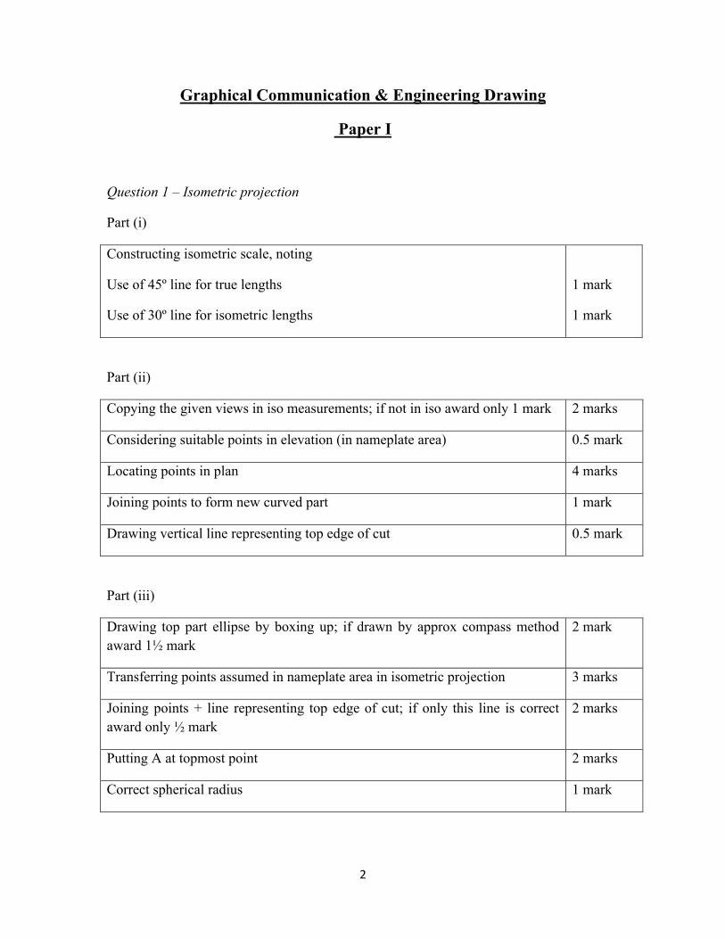
Graphical Communication & Engineering Drawing
Paper I
Question 1 – Isometric projection
Part (i)
Constructing isometric scale, noting
Use of 45º line for true lengths
Use of 30º line for isometric lengths
1 mark
1 mark
Part (ii)
Copying the given views in iso measurements; if not in iso award only 1 mark 2 marks
Considering suitable points in elevation (in nameplate area) 0.5 mark
Locating points in plan 4 marks
Joining points to form new curved part 1 mark
Drawing vertical line representing top edge of cut 0.5 mark
Part (iii)
Drawing top part ellipse by boxing up; if drawn by approx compass method award 1½ mark
2 mark
Transferring points assumed in nameplate area in isometric projection 3 marks
Joining points + line representing top edge of cut; if only this line is correct award only ½ mark
2 marks
Putting A at topmost point 2 marks
Correct spherical radius 1 mark
3
Question 2 – Palmate section
Part (i)
Copying the given views 2 marks
Part (ii)
Assuming suitable points in given plan 1
Points correctly located in auxiliary elvn; if only the top point is correct award only ½ mark
6
View correctly lined 1
Part (iii)
Good corresponding use of XY and X1Y1; points correctly located in ordinary elevation; if only the bottom squarish part is correct award 1.5 marks.
8
Correct points correctly joined 2
Question 3 – Screw threads
External 2-start LH square thread
Using a pitch of helices of 48mm; award even if the thread drawn is a vee thread
1mark
Dividing 48mm into 12 parts; award even if the thread drawn is a vee thread 1
Finding square cross-section as 12 x 12; 1
Finding root diameter and drawing corresponding plan 0.5
Drawing major diameter and its corresponding plan; award even if the thread drawn is a vee thread
0.5
Drawing four LH helices on root diameter; drawing four LH helices on major 2
4
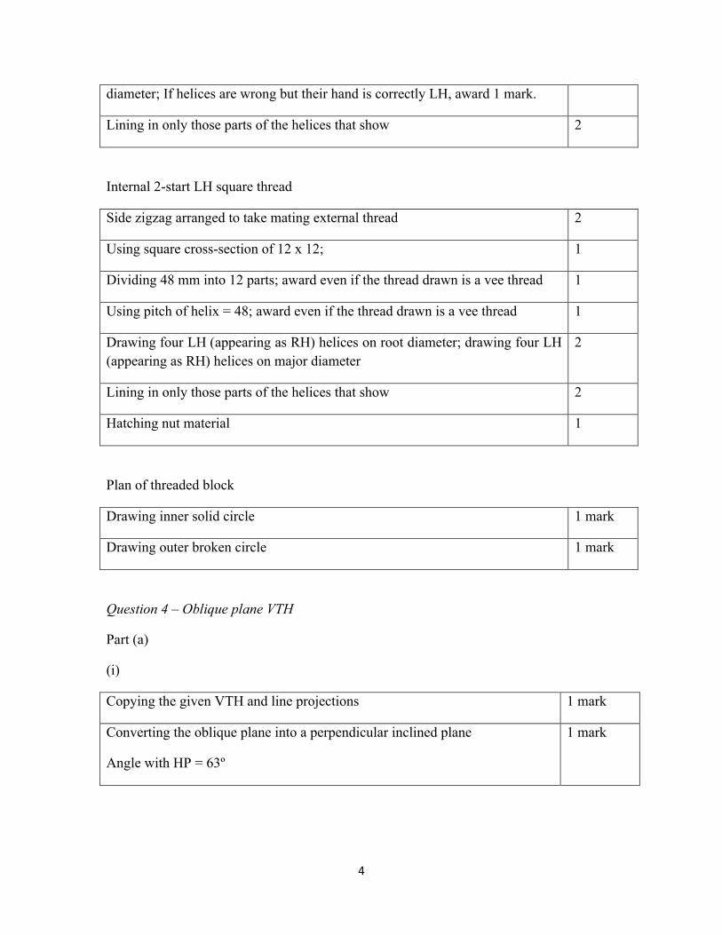
diameter; If helices are wrong but their hand is correctly LH, award 1 mark.
Lining in only those parts of the helices that show 2
Internal 2-start LH square thread
Side zigzag arranged to take mating external thread 2
Using square cross-section of 12 x 12; 1
Dividing 48 mm into 12 parts; award even if the thread drawn is a vee thread 1
Using pitch of helix = 48; award even if the thread drawn is a vee thread 1
Drawing four LH (appearing as RH) helices on root diameter; drawing four LH (appearing as RH) helices on major diameter
2
Lining in only those parts of the helices that show 2
Hatching nut material 1
Plan of threaded block
Drawing inner solid circle 1 mark
Drawing outer broken circle 1 mark
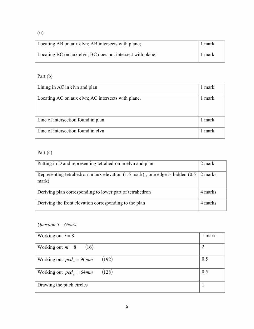
Question 4 – Oblique plane VTH
Part (a)
(i)
Copying the given VTH and line projections 1 mark
Converting the oblique plane into a perpendicular inclined plane
Angle with HP = 63º
1 mark
5
(ii)
Locating AB on aux elvn; AB intersects with plane;
Locating BC on aux elvn; BC does not intersect with plane;
1 mark
1 mark
Part (b)
Lining in AC in elvn and plan 1 mark
Locating AC on aux elvn; AC intersects with plane. 1 mark
Line of intersection found in plan 1 mark
Line of intersection found in elvn 1 mark
Part (c)
Putting in D and representing tetrahedron in elvn and plan 2 mark
Representing tetrahedron in aux elevation (1.5 mark) ; one edge is hidden (0.5 mark)
2 marks
Deriving plan corresponding to lower part of tetrahedron 4 marks
Deriving the front elevation corresponding to the plan 4 marks
Question 5 – Gears
Working out 8t 1 mark
Working out 168m 2
Working out 19296mmpcdw 0.5
Working out 12864mmpcd p 0.5
Drawing the pitch circles 1
6
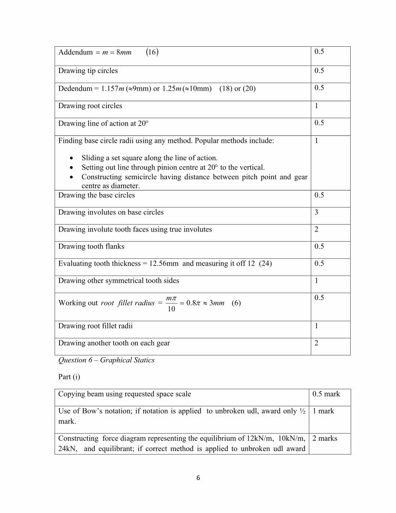
Addendum 168mmm 0.5
Drawing tip circles 0.5
Dedendum = m157.1 (9mm) or m25.1 (10mm) (18) or (20) 0.5
Drawing root circles 1
Drawing line of action at 20 0.5
Finding base circle radii using any method. Popular methods include:
Sliding a set square along the line of action. Setting out line through pinion centre at 20 to the vertical. Constructing semicircle having distance between pitch point and gear
centre as diameter.
1
Drawing the base circles 0.5
Drawing involutes on base circles 3
Drawing involute tooth faces using true involutes 2
Drawing tooth flanks 0.5
Evaluating tooth thickness = 12.56mm and measuring it off 12 (24) 0.5
Drawing other symmetrical tooth sides 1
Working out radiusfilletroot = mmm
38.010
(6)
0.5
Drawing root fillet radii 1
Drawing another tooth on each gear 2
Question 6 – Graphical Statics
Part (i)
Copying beam using requested space scale 0.5 mark
Use of Bow’s notation; if notation is applied to unbroken udl, award only ½ mark.
1 mark
Constructing force diagram representing the equilibrium of 12kN/m, 10kN/m, 24kN, and equilibrant; if correct method is applied to unbroken udl award
2 marks
7
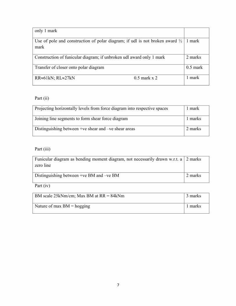
only 1 mark
Use of pole and construction of polar diagram; if udl is not broken award ½ mark
1 mark
Construction of funicular diagram; if unbroken udl award only 1 mark 2 marks
Transfer of closer onto polar diagram 0.5 mark
RR61kN; RL27kN 0.5 mark x 2 1 mark
Part (ii)
Projecting horizontally levels from force diagram into respective spaces 1 mark
Joining line segments to form shear force diagram 1 marks
Distinguishing between +ve shear and –ve shear areas 2 marks
Part (iii)
Funicular diagram as bending moment diagram, not necessarily drawn w.r.t. a zero line
2 marks
Distinguishing between +ve BM and –ve BM 2 marks
Part (iv)
BM scale 25kNm/cm; Max BM at RR = 84kNm 3 marks
Nature of max BM = hogging 1 marks

8
Graphical Communication
Paper II
Question 1 – Estimated perspective drawing-Entrance hall.
Part (i)
Typical sketches would be generated by:
Start by taking HL in the middle of the height, VP in the middle resulting in balanced emphasis
1 mark
Taking HL shifted up, emphasising more the floor area, VP moved to the right. This is preferred to represent the spaciousness of the layout.
1 mark
Taking HL shifted down, drawing more attention to the areas in the upper half height of the room.
1 mark
Part (ii)
Representing room proportions 3
Representing viewing direction 3
Good use of paper space 3
Constructing a grid that respects the laws of perspective 6 marks
Representing the stairs 2
Representing the piano & stool 2
Representing the table 1
Representing the frames and mirror 1
Representing the doorway 2
Representing the chest of drawers 1
Representing the plant pot 1
9
Part (iii)
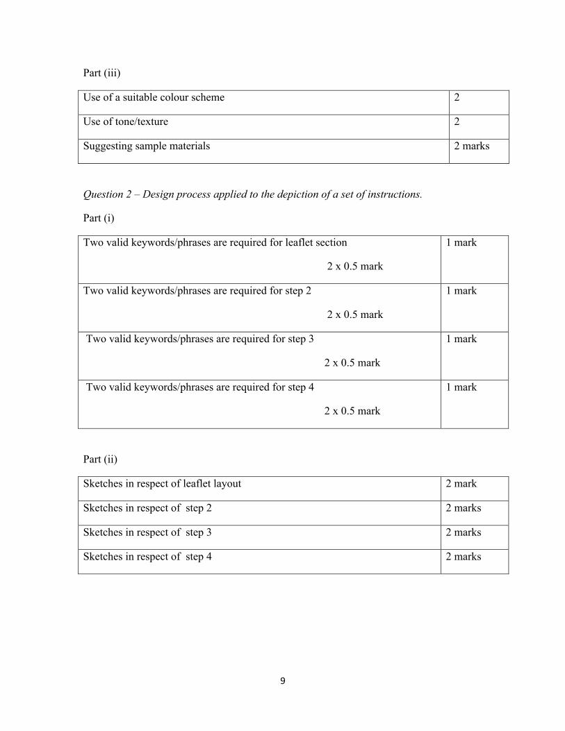
Use of a suitable colour scheme 2
Use of tone/texture 2
Suggesting sample materials 2 marks
Question 2 – Design process applied to the depiction of a set of instructions.
Part (i)
Two valid keywords/phrases are required for leaflet section
2 x 0.5 mark
1 mark
Two valid keywords/phrases are required for step 2
2 x 0.5 mark
1 mark
Two valid keywords/phrases are required for step 3
2 x 0.5 mark
1 mark
Two valid keywords/phrases are required for step 4
2 x 0.5 mark
1 mark
Part (ii)
Sketches in respect of leaflet layout 2 mark
Sketches in respect of step 2 2 marks
Sketches in respect of step 3 2 marks
Sketches in respect of step 4 2 marks
10
Part (iii)
Any method of effective identification is accepted 1 mark
Part (iv)
How effective is the design to convey the message 3 marks
For the use of simple quality linework 3 marks
For the use of colour, tone and texture 3 marks
Question3 – Design process applied to the production of ideogrammatic images
Part (i)
Six valid keywords/phrases are required to award full marks
6 x 0.5 marks
3 marks
Part (ii)
Minimum of 3 sketches are required 3 x 2 marks 6 marks
Part (iii)
Any method of effective identification is accepted 1 mark
.
Part (iv)
How effective is the design to convey the message 4 marks
11
For the use of simple quality linework 4 marks
For the use of colour, tone and texture 4 marks
Question 4 – Comparison and representation of data
Part (i) 3D representation
Representing the theme of Backpacks 2 marks
Representing holding volume and its data values 2 marks
Representing no.of compartments and its data values 3 marks
Representing cost and its data values 2 marks
For the effective use of colour
Using contrasting colours for adjacent models Using the same colour for different aspects of the same model
3 marks
Part (ii) 2D comparison
Representing the theme of Backpacks 2 marks
Representing fabric quality and its data values 2 marks
Representing shoulder strap quality and its data values 2 marks
Representing rear panel quality and its data values 2 marks
For the effective use of colour
Using contrasting colours for adjacent models Using the same colour for different aspects of the same model
2 marks
12
Question 5 - Design of touristic symbols and leaflet front page
Part (a)
For each of the eight activities:
For preliminary sketch: 0.5 mark
For final symbol:
How effective is the symbol to represent the feature 0.5 mark
For the use of simple quality linework 0.5 mark
For the use of colour, tone and texture 0.5 mark
8x 2 marks
16 marks
Part (b)
For front page design:
How suitable and effective is the design 3 mark
For the use of simple quality linework 1 mark
For the use of colour, tone and texture 2 mark
6 marks
13
Engineering Drawing
Paper II
Question 1 – Machine drawing – Tailstock
Part (i) Sectional front elevation
+ Tailstock body
Drawing body outline 3
Hatching all, 2
Except hole in base for bolt to secure tailstock to lathe bed 1
Except webs parallel to cutting plane 1
+ Barrel
Drawn at the correct position, 12mm from front edge of tailstock body 1
Hatching all (opposite direction), 1
Except inner bore 1
Except keyway all along the barrel 1
+ Endcap
Hatching all (may be opposite to that on tailstock body) + outline 1
Line to represent external thread on endcap body; reptg u’cut 1
Remaining part of female matching thread in body (hatched) 1
+Bush in endcap
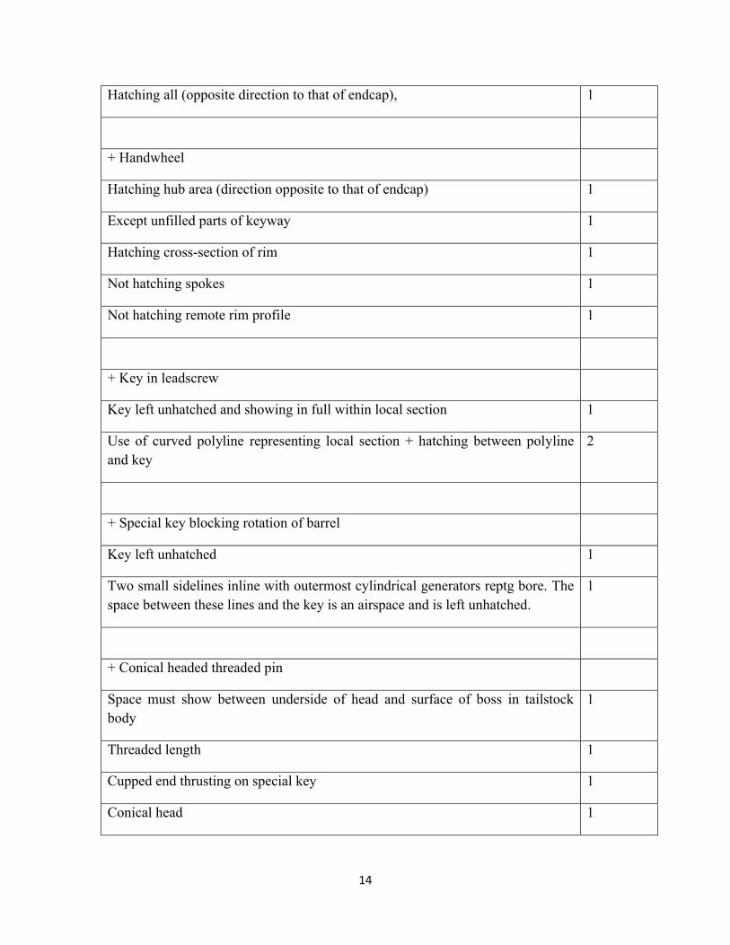
14
Hatching all (opposite direction to that of endcap), 1
+ Handwheel
Hatching hub area (direction opposite to that of endcap) 1
Except unfilled parts of keyway 1
Hatching cross-section of rim 1
Not hatching spokes 1
Not hatching remote rim profile 1
+ Key in leadscrew
Key left unhatched and showing in full within local section 1
Use of curved polyline representing local section + hatching between polyline and key
2
+ Special key blocking rotation of barrel
Key left unhatched 1
Two small sidelines inline with outermost cylindrical generators reptg bore. The space between these lines and the key is an airspace and is left unhatched.
1
+ Conical headed threaded pin
Space must show between underside of head and surface of boss in tailstock body
1
Threaded length 1
Cupped end thrusting on special key 1
Conical head 1
15
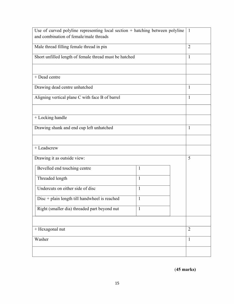
Use of curved polyline representing local section + hatching between polyline and combination of female/male threads
1
Male thread filling female thread in pin 2
Short unfilled length of female thread must be hatched 1
+ Dead centre
Drawing dead centre unhatched 1
Aligning vertical plane C with face B of barrel 1
+ Locking handle
Drawing shank and end cup left unhatched 1
+ Leadscrew
Drawing it as outside view:
Bevelled end touching centre 1
Threaded length 1
Undercuts on either side of disc 1
Disc + plain length till handwheel is reached 1
Right (smaller dia) threaded part beyond nut 1
5
+ Hexagonal nut 2
Washer 1
(45 marks)
16
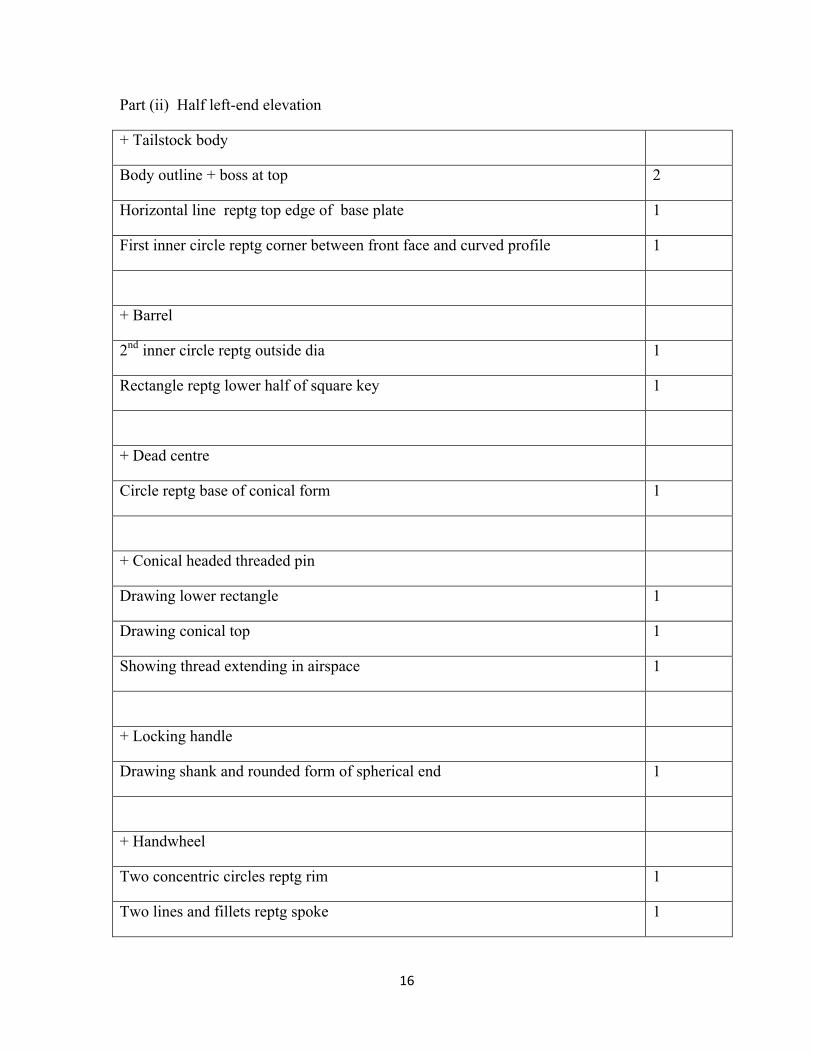
Part (ii) Half left-end elevation
+ Tailstock body
Body outline + boss at top 2
Horizontal line reptg top edge of base plate 1
First inner circle reptg corner between front face and curved profile 1
+ Barrel
2nd inner circle reptg outside dia 1
Rectangle reptg lower half of square key 1
+ Dead centre
Circle reptg base of conical form 1
+ Conical headed threaded pin
Drawing lower rectangle 1
Drawing conical top 1
Showing thread extending in airspace 1
+ Locking handle
Drawing shank and rounded form of spherical end 1
+ Handwheel
Two concentric circles reptg rim 1
Two lines and fillets reptg spoke 1
17
+ General
Vertical centreline + drawing elements projecting slightly beyond 1
Use of two sets of two horizontal lines to represent symmetrical view 1
(15 marks )
(60 marks total)
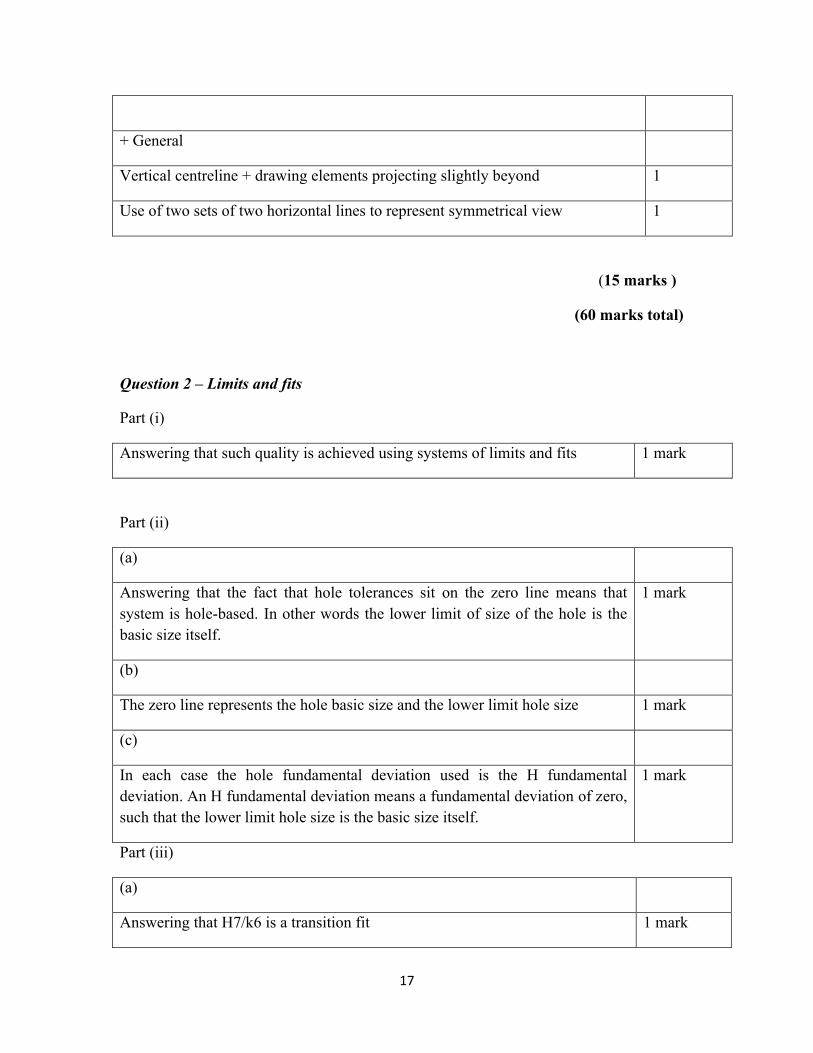
Question 2 – Limits and fits
Part (i)
Answering that such quality is achieved using systems of limits and fits 1 mark
Part (ii)
(a)
Answering that the fact that hole tolerances sit on the zero line means that system is hole-based. In other words the lower limit of size of the hole is the basic size itself.
1 mark
(b)
The zero line represents the hole basic size and the lower limit hole size 1 mark
(c)
In each case the hole fundamental deviation used is the H fundamental deviation. An H fundamental deviation means a fundamental deviation of zero, such that the lower limit hole size is the basic size itself.
1 mark
Part (iii)
(a)
Answering that H7/k6 is a transition fit 1 mark
18
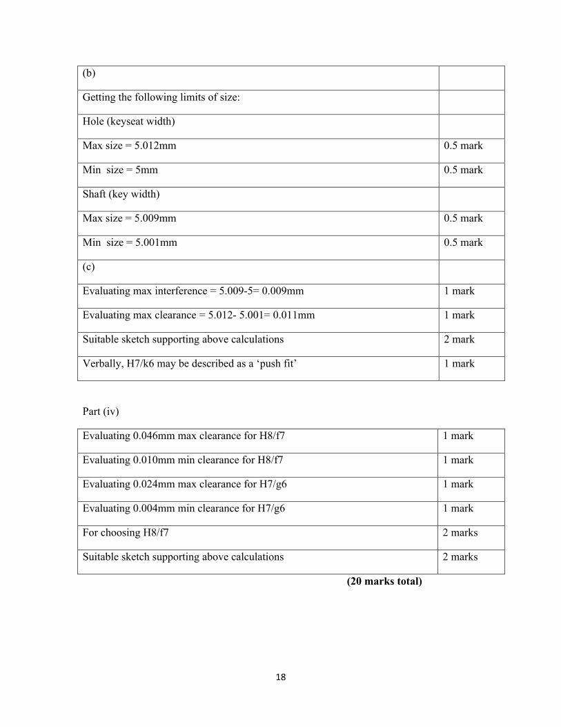
(b)
Getting the following limits of size:
Hole (keyseat width)
Max size = 5.012mm 0.5 mark
Min size = 5mm 0.5 mark
Shaft (key width)
Max size = 5.009mm 0.5 mark
Min size = 5.001mm 0.5 mark
(c)
Evaluating max interference = 5.009-5= 0.009mm 1 mark
Evaluating max clearance = 5.012- 5.001= 0.011mm 1 mark
Suitable sketch supporting above calculations 2 mark
Verbally, H7/k6 may be described as a ‘push fit’ 1 mark
Part (iv)
Evaluating 0.046mm max clearance for H8/f7 1 mark
Evaluating 0.010mm min clearance for H8/f7 1 mark
Evaluating 0.024mm max clearance for H7/g6 1 mark
Evaluating 0.004mm min clearance for H7/g6 1 mark
For choosing H8/f7 2 marks
Suitable sketch supporting above calculations 2 marks
(20 marks total)
19
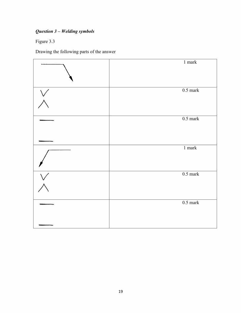
Question 3 – Welding symbols
Figure 3.3
Drawing the following parts of the answer
1 mark
0.5 mark
0.5 mark
1 mark
0.5 mark
0.5 mark

20
Figure 3.4
Drawing the following parts of the answer
1 mark
2 mark
Figure 3.5
Drawing the following parts of the answer
0.5 mark
1 mark
with top fillet
0.5 mark
1 mark
21
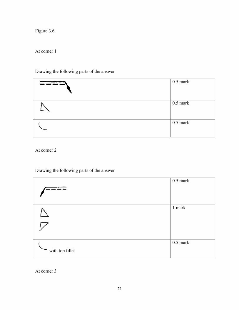
Figure 3.6
At corner 1
Drawing the following parts of the answer
0.5 mark
0.5 mark
0.5 mark
At corner 2
Drawing the following parts of the answer
0.5 mark
1 mark
with top fillet
0.5 mark
At corner 3
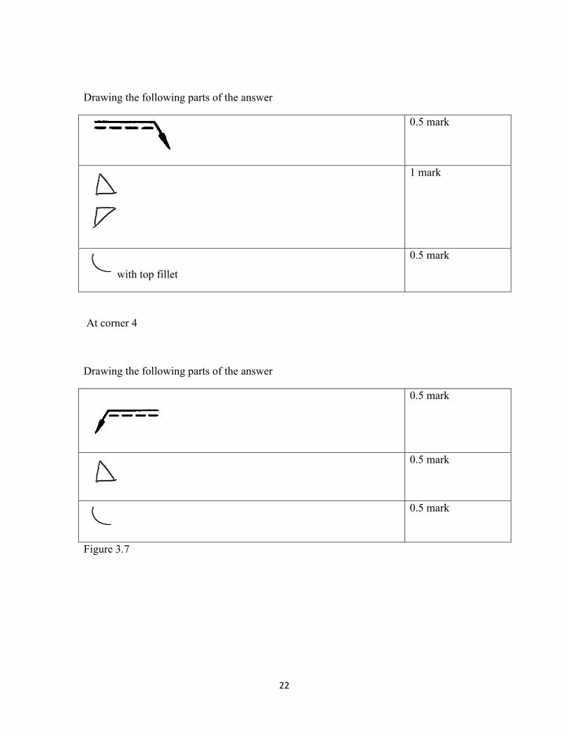
22
Drawing the following parts of the answer
0.5 mark
1 mark
with top fillet
0.5 mark
At corner 4
Drawing the following parts of the answer
0.5 mark
0.5 mark
0.5 mark
Figure 3.7
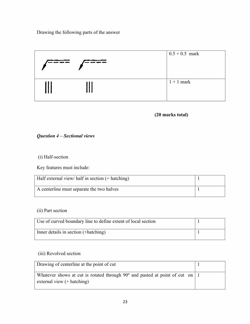
23
Drawing the following parts of the answer
0.5 + 0.5 mark
1 + 1 mark
(20 marks total)
Question 4 – Sectional views
(i) Half-section
Key features must include:
Half external view/ half in section (+ hatching) 1
A centerline must separate the two halves 1
(ii) Part section
Use of curved boundary line to define extent of local section 1
Inner details in section (+hatching) 1
(iii) Revolved section
Drawing of centerline at the point of cut 1
Whatever shows at cut is rotated through 90º and pasted at point of cut on external view (+ hatching)
1
24
If lines from the original external view pass through the section these should be removed for the lengths affected.
1
(iv) Section staggered across parallel planes
Lines resulting from corners of staggered cutting plane are not represented (+ hatching)
1
Corners of staggered cutting plane should be drawn in double thickness 1
Part sections resulting from different parts of the cutting plane are aligned in one plane.
1
(v) Sections bent through an angle
Line resulting from bent form of cutting plane is not represented (+ hatching) 1
Areas cut by bent part of cutting plane are first swung onto the vertical plane and then projected normally
2
Corners of bent cutting plane should be drawn in double thickness 1
Proper drawing of ends of cutting planes 2
Proper hatching at 45º at proper spacing 2
Proper use of centrelines 2
(20 marks total)