university of salerno department of mechanical …department of mechanical engineering university...
TRANSCRIPT

UNIVERSITY OF SALERNODepartment of Mechanical Engineering
UNIVERSITY RESEARCH OPPORTUNITIES: ELEMENTS OF HYDRAIL DESIGN
Angelo Esposito, Cesare Pianese, Marco [email protected]
Fourth International Hydrail Conference
June 9, 2008, Valencia Spain
Agendag
• Energy scenario (Motivations)– Future trends and role of Hydrogen– Well to wheel analysis– Well to wheel analysis
• Hydrogen and Fuel Cells technologies (Solutions)H2 d ti t t t– H2 production, transport, storage
– FC technologies (PEM, SO, PA) for train applications
• Future (R&D)• Future (R&D)– Research needs– Short and medium term visionShort and medium term vision
174

Energy Scenariogy
dia
Security of
Sour
ce: W
ikip
edSecurity ofsupply
S
A il biliPollution
Availability
100Crude oil prices
AffordabilityGlobal
warming Jan 2008
40
60
80
100
$/b
bl
1947 1957 1967 1977 1987 1997 20070
20
40
year
$
175

Future Energy Trendsgy• World energy demand by
Fuel Type eaFuel Type.• Business as usual will lead
to an increase of fossil MB
tu
w.e
ia.d
oe.g
ov/ie
fuels (about 55%) by 2030.
M
Sour
ce:
ww
w
100World Primary Energy Diversification• Oil companies envisage a
di ifi ti
60
80
100m
arke
t COAL NATURAL GAS2005
Com
pany
om
diversification process towards gaseous fuels.
• Methane is the medium
20
40
60
% o
f tot
al m
WOODOIL
SOLAR/H2
ted
from
GH
K C
ww
w.g
hkco
.coMethane is the medium
term solution. • Hydrogen will complete the
t iti f CO f
1850 1900 1950 2000 2050 2100 21500
20
year
NUCLEAR Adaptransition for a CO2 - free
society.176

Hydrogen: advantagesy g g• Energy carrier.gy• Possibility to use any primary source, conventional or
renewable.• Alternative to fossil fuels increasing renewable energy
sources.R d i d d il• Reducing dependency on oil.
• Energy conversion technologies (i e FC) have high• Energy conversion technologies (i.e. FC) have highenergy conversion efficiencies.
• Reduction of GHG without harmful emissions.Reduction of GHG without harmful emissions.• Direct combustion of Hydrogen in thermal engines does
not produce CO, CO2, PM.p 2
177

Well to Wheel AnalysisyThe hydrogen pathway: sources, production and use
SOURCE PROCESS CARRIER USE
WTT TTW
ENTI
ON
AL SOURCE PROCESS CARRIER USE
Mobile
CO
NVE
AutomobileBus
Train
exac
o
BLE
TrainShipPlane
from
Che
vron
Te
REN
EWA Stationary
Pow. Gen.APU
Adap
ted
fAPUCogen.
178

Agendag
• Energy scenario (Motivations)– Future trends and role of Hydrogen– Well to wheel analysis– Well to wheel analysis
• Hydrogen and Fuel Cells technologies (Solutions)H2 d ti t t t– H2 production, transport, storage
– FC technologies (PEM, SO, PA) for train applications
• Future (R&D)• Future (R&D)– Research needs– Short and medium term visionShort and medium term vision
179

H2 production and delivery2 p yShort Term Option Long Term Option
M.O
gden
Afte
r J.
M
180

Onboard Hydrogen Storagey g gHydrogen can be stored in four different ways:
I d f i hi h t k yneT
ek
• In compressed form: in high-pressure tanks or gas cylinders made of ultra-light composite materials; they are used in prototype fuel cell automobiles
Sour
ce: D
y
and buses.• In liquid form: in super isolated tanks as cryogenic
liquid (at -253°C) teyrliquid (at -253 C).
• In a bonded form in a solid compound by:– adsorbing (carbon structures…); ur
ce: M
agna
St
– absorbing (simple crystalline hydrides);– chemically reacting (complex and chemical hydrides).
I fl id d f b h i ll ti
So
r• In a fluid compound form by chemically reacting(e.g. methanol, ammonia, etc).
• Solutions may be chosen according to application
Day
mle
r Chr
ysle
y g ppsecurity issues.
Sour
ce: D
181

Fuel Cells• Fuel Cells are energy conversion systems, which
directly combine H2 and O2 to generate electricity. FCs generate also water and heat O
EFCs generate also water and heat.• FCs have high efficiency (TTW), no moving parts,
simple design, silent operation.
Sour
ce: D
O
p g , p• Auxiliaries are required (BOP) for proper FC stack
working.
nie
& D
icks
ted
from
Lar
min
PEMFC=polymer electrolyte membrane; DMFC=direct methanol; AFC=alkaline; PAFC=phosphoric acid; MCFC=molten carbonate; SOFC=solid oxide.
Adap
t
182

FC Auxiliaries• Appropriate components selection and sizing to meet
application requirements.
H
application requirements.• Optimized working operation to reduce parasitic losses.
humidificationh b
C
H2
H2 tankMFC FC Stack
chamber
heat humidification
fuelcell
stackair
EM
EM
BPV
2
for P
E
exchanger chamberstackC
Tcoolingwaterifi
cati
ater FC: B
OP
f
heatexchanger
P
P
P
hum
idon
w outletwater
watertankam
ple:
P
N2 and O2
tank
Ex
183
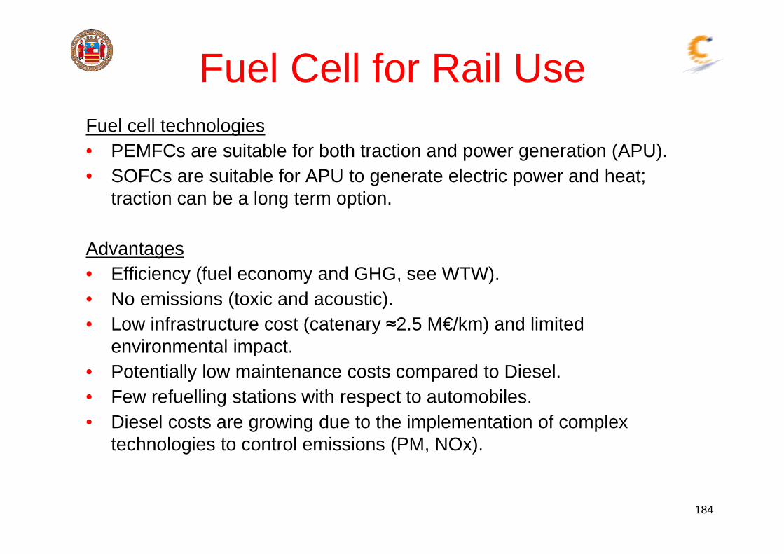
Fuel Cell for Rail UseFuel cell technologies• PEMFCs are suitable for both traction and power generation (APU)• PEMFCs are suitable for both traction and power generation (APU).• SOFCs are suitable for APU to generate electric power and heat;
traction can be a long term option.
Advantages• Efficiency (fuel economy and GHG see WTW)Efficiency (fuel economy and GHG, see WTW).• No emissions (toxic and acoustic).• Low infrastructure cost (catenary 2.5 M€/km) and limited
i t l i tenvironmental impact.• Potentially low maintenance costs compared to Diesel.• Few refuelling stations with respect to automobiles. g p• Diesel costs are growing due to the implementation of complex
technologies to control emissions (PM, NOx).
184

FC Hybrid Propulsiony pBenefits
Recovering braking energy for electric• Recovering braking energy for electricpropulsion.
• Batteries allow downsizing the primary energy conversion system.
• Powertrain hybridization could act as a bridge to fuel cell train introduction.a bridge to fuel cell train introduction.
ChallengesDriverDriver
Powercontrolg
• Optimal system integration.• Optimal energy management to
ensure:
DL VMU
Intermediate LevelFC-S-CC-C
High LevelDL VMU
Intermediate LevelFC-S-CC-C
High Level
ensure:– Safe stack operation (avoiding highly
fluctuating load).Ch t i i (t t d b tt
EM
Comp. Humid. …
Intermediate Level
FCS
Low LevelEM
Comp. Humid. …
Intermediate Level
FCS
Low Level
– Charge sustaining (to extend batterylifetime and efficiency). B
Energy Flow DH>0 Energy Flow DH=0
Control Actions Driver Interactions
B
Energy Flow DH>0 Energy Flow DH=0
Control Actions Driver Interactions

PEM Hybrid powertain controlUNISA Multi-level control architecture
High LevelHigh LevelTMUTMU
Intermediate LevelIntermediate Level
FCS
Low Level
FCS
Low Level
FCSFCS
186
Energy Flow DH>0 Energy Flow DH=0
Control Actions Driver InteractionsEnergy Flow DH>0 Energy Flow DH=0
Control Actions Driver Interactions

Agendag
• Energy scenario (Motivations)– Future trends and role of Hydrogen– Well to wheel analysis– Well to wheel analysis
• Hydrogen and Fuel Cells technologies (Solutions)H2 d ti t t t– H2 production, transport, storage
– FC technologies (PEM, SO, PA) for train applications
• Future (R&D)• Future (R&D)– Research needs– Short and medium term visionShort and medium term vision
187

Fuel Cells Research NeedsFuel Cell Stack
Red ce stack costs• Reduce stack costs.• Increase durability.• Increase power density (higher current densities and lower
Trade-off
p y ( gresistance).
F l C ll S t (St k & BOP)Fuel Cell System (Stack & BOP)• Thermal, Air and Water Management• R&D in auxiliary devices: compressor/expanders reformersR&D in auxiliary devices: compressor/expanders, reformers.• Fuel cell system configuration and efficiency.• Start-up time and cold start.• Control and diagnostics; sensors and actuators.• Packaging in vehicle applications.
188

Research TargetsgRoad propulsion• 10 50 times cost reduction:
Stationary5 10 times cost reduction: en
tatio
n Pl
an
• 10-50 times cost reduction:100€/kW (PEM FCS);
• 10 khr durability (Buses).
• 5-10 times cost reduction:1000€/kW;
• 50 khr durability.RAIL
e: H
FP I
mpl
eme
Sou
rce
• Technological/Economical barriers:– Improve electrochemistry (membranes, electrodes, catalysts).– New materials and concept.New materials and concept.– Fluid mechanics (heat and mass transfer).– Economy of scale and technology learning.
• Optimal design/configuration:– Balance of plant.– Hybridization: Mild (APU); Full (Fuel cell + batteries/supercap).
189

Conclusions 1/2• The application of PEM Fuel Cell Systems requires
improvements to reduce costs and improve durabilityimprovements to reduce costs and improve durability.• Transfer of fuel cell technology from automotive to other
markets can contribute to stack cost reduction.markets can contribute to stack cost reduction.• A hydrogen train will only have a 15% extra cost with
respect to ordinary Diesel unit (source: British RSSB)• In the short term PEM is a viable solution for APU.• Hybrid powertrains can be developed in the medium term.
Basic research will focus f fon core technologies to improve materials for performance
enhancement (power density, durability), costs, manufacturing vibration crashworthinessmanufacturing, vibration, crashworthiness.
190

Conclusions 2/2Applied research is needed• to define the role of fuel cell system (traction, APU) and y ( )
proper powertrain solution (e.g. full hybrid, range extender);• to develop and implement ad hoc auxiliary system (BOP);• to customize the plant to meet user requirements (vehicle
layout and configuration);t i hi l i t ti b d h d t• to improve vehicle integration, on-board hydrogen storageand refueling;
• to implement proper control strategies able to maximize FC• to implement proper control strategies able to maximize FCbenefits for energy and emission optimization;
• to develop diagnostics system to guarantee lifelong andto develop diagnostics system to guarantee lifelong andsafe operation;
• to develop FCS computational tools to support both design and engineering phases.
191