university of technology, jamaica -...
TRANSCRIPT

UNIVERSITY OF TECHNOLOGY, JAMAICA SCHOOL OF ENGINEERING
POWER SYSTEMS PROTECTION
Fault Analysis Aims
• To determine the relationship between fault points and fault severity � To determine method/s of limiting the flow of fault currents within a power system � To determine switchgear ratings � To determine the influence of transformer and plant connections on fault currents
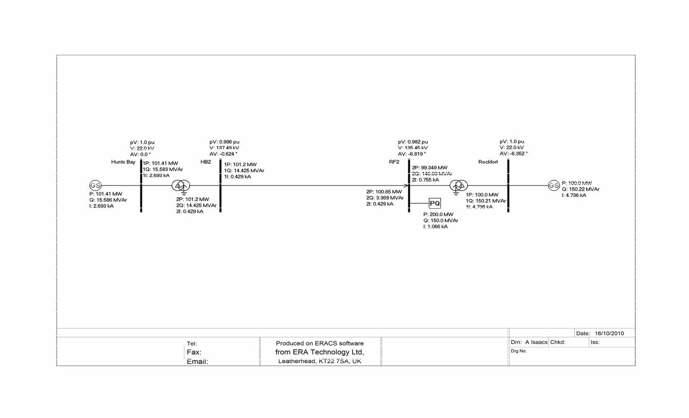
Introduction In this exercise you will continue to use the ‘ERACS’ power system analysis software package using the fault analysis, or short circuit function. Getting started Enter the ERACS package and select a new database and network, give a new study name and check that the base MVA is set at 100. Input the system shown in Figure 1 into ERACS, the plant parameters are given in appendix 1; create new library keys as necessary. Since fault conditions are influenced by the operating state of the power system, it is necessary to run the load flow program before attempting any short circuits. Run the loadflow now and ensure that a stable solution can be found. We will now apply a fault to the system. The fault will be a single phase to earth type, located at the midpoint (50%) of line 1. Figure 2 shows the results of this fault, where the phase currents are displayed. Note that the current at the fault point is 8691 A, which is almost equal to the sum of the current contributions from BUS HB2 and BUS RF2. Exercises Exercise 1 Find the currents in the fault path, from BUS 1 and from BUS 2, as a single phase to earth fault is moved from 0% (i.e. the fault is on BUS 1) to 100% (the fault is on BUS 2) along the line in 20 % increments. Record your results below: Position of Fault Current if fault path Current from BUS 1 Current from BUS 2 0% (RF2) 10% 20% 30% 40% 50% 60% 70% 80% 90% 100% (HB2) Plot these values on graph paper. The fault current contribution from each busbar will influence the choice of circuit breaker (CB)


rating used, ultimately, to disconnect the fault from the system. To decide the CB rating, a short circuit analysis is performed — similar to this exercise. If you had to decide a rating for a CBs on the line, which position of the fault would you mainly be concerned with? Exercise 2 Reposition the fault at 50% and record the line current values for each fault type:
Fault type Current from BUS 1 Current from BUS 2 R Y B R Y B � – earth � – � � – � - earth � – � – �
a. Which fault type has the most influence on CB rating?
b. Which fault type has the least influence on CB rating?
c. Determine the phase currents in the generators and transformers during these faults
d. Comment on these currents relative to the currents at the fault point
e. Determine the sequence currents (by selecting this option from the results menu) in the transformers and generators for the faults
f. Verify the phase currents in one of the transformers and a generator.
Exercise 3 Change the high voltage windings of TRANS 2 to Star a connection (the winding is originally Grounded Star). Record the line current values for a single phase to earth fault at 50% along the line. Fault type Current from BUS 1 Current from BUS 2 R Y B R Y B � – earth � – earth unearthed
a. Compare the line current values with and without the star point earthed at TRANS 2. Explain why they are different:
b. Compare the sequence currents for this connection with those values determined in
exercise 2. Exercise 4 Reinstate the star point earthing on TRANS 2. Edit TRANS 1 and TRANS 2 to include a 20 � neutral earthing resistor. Examine the effect on all fault types at 50%:
Fault type Current from BUS 1 Current from BUS 2 R Y B R Y B � – earth � – � � – � - earth � – � – � Explain why some fault types are influenced, but others are not:

Exercise 5 Edit GEN 1 to also include a 20 � neutral earthing resistor; conduct tests to examine the influence, if any, of the generator neutral resistor on faults occurring at BUS HB2 (the 138 kV bus) and BUS 3 (the 22 kV bus).
a. Briefly describe and justify the effect on BUS HB2 (the 138 kV bus).
b. Briefly describe and justify the effect on BUS Hunts Bay (the 22 kV bus).
c. Neutral earthing resistors are commonly used in power systems. From your experience in this exercise explain why they are used.
Exercise 6 The term fault level gives an indication of the expected severity of faults. Fault level (FL) is defined as: FL= �3 * VL * Isc where VL is rated line voltage and ISC is the maximum short circuited line current.
• Calculate the three phase fault level for four busbars. Verify these results by selecting the fault level option display for these busbars.
Exercise 7 Modify your network as shown in Figure 3 (the load flow results are shown in this figure). The line parameters are similar to that between Hunts Bay and Rockfort. The rating of the new load is 25MW and 10 MVar. The original load is also adjusted to 50 MW and 25 MVar.
a. With the new load switched out, rerun the single line to ground fault at the centre on the Hunts Bay to Rockfort line.
b. Switch in the new load and rerun the fault.
c. Switch out the Rockfort generator and the new load and once again rerun the fault.
d. With the generator still out of service, reconnect the new load and rerun the fault.
Determine the impact of load and generation on system faults. (you may wish to conduct studies on other fault types. Andrew Isaacs August 2010


Appendix Plant parameters for 4 busbar system Hunts Bay: 500 MVA, 400 MW, 22 kV, 50Hz Slack generator, voltage = 1.0 p.u. angle 00 R1 = 0.00 1 p.u. on rating X1 = 0.01 p.u. on rating R2 = 0.002p.u. on rating X2 = 0.02p.u. on rating R0 = 0.01 p.u. on rating X0 = 0.02 p.u. on rating Rockfort: 500 MVA, 400 MW, 22 kV, 50 Hz PV generator, Voltage = 1.0 p.u., real power output = 100 MW R1 = 0.00 1 p.u. on rating X1 = 0.01 p.u. on rating R2 = 0.002p.u. on rating X2 = 0.02p.u. on rating R0 = 0.01 p.u. on rating X0 = 0.02 p.u. on rating TRANS 1 22 kV winding: 500 MVA, delta, winding angle = 300
Winding resistance and leakage reactance values (to 100 MVA base): R0 = R1 = 0.001 p.u.
X0 = X1 = 0.01 p.u. 138 kV winding: 500 MVA, grounded star
Winding resistance and leakage reactance values (to 100 MVA base): R0 = R1 = 0.001 p.u.
X0 = X1 = 0.001 p.u. TRANS 2 as TRANS 1 Transmission line parameters Unit rating 2 kA R0 = 5� X0 = 50 � R1 = 1 � X1 = 20 � LOAD1:138kV,200MW, 150MVAr