university - tu delfthomepage.tudelft.nl/x4x4j/aereports/lab_4/jasper_hendriks_the... · point...
TRANSCRIPT
1
2
University: TU Delft Study: Architectural Engineering Phase: MSC 4
Course: Graduation Thesis Code: AR3AE015
Chair Holder: prof. ir. Thijs Asselbergs Design Mentor: ir. Jan Engels Engineering Mentor: ir. Frank Schnater External Examiner: ir. Daan Vitner
Name: Jasper Hendriks Number: B1345583 Internet: www.jahendriks.nl
Report: the Suspended Veil Handed over: April 8, 2011

3
In the early phase of the graduation process, three different programs where described for the design: creating visual
connections through weaving, stimulating the senses of the visitors and a mechanical adaptation to the size of the art
collections. Within each one of these programs, a design concept was formulated and should have created a synergy.
However, during the design process it was very difficult for me to create one single design out of these programs; they were
very different from one another. Also their design concepts were very large to begin with and I immediately had some
doubts on their meaning and purpose. Not to mention that each of the programs could be made into a design. Eventually I
neglected two of the three programs and by doing so I could focus myself to one main program: creating a design based
upon weaving combined with a leveled identity.
Preface
The word “weaving” can be interpreted in very different ways. We all know that a mesh consists out of weaves, on turn
weaves consists out of wires. A piece of cloth has a weaving pattern and so does the construction of a building in 3D or even
its plan-layout in 2D. Weaves can be seen everywhere you go and where you can’t go (does 4D weaving exists or can it only
be described as time?). One major problem I had with the concept of weaving was: where does it start? For instance: a
point direct to another point gives me a line or wire (1D). Within every weaving pattern you see the lines, but where are the
lines coming from and where does it go to? Should the construction of any given building be seen as one continuous weave
without a start or an end? Or does the construction consists out of separated lines with a starting-point at where they
connect each other. In my opinion a lot of time has been wasted on this topic. At this moment I still do not have a clear
answer to all those questions. Through categorizing different weaves and their purposes, I could made the weaving concept
in such a way that it is comprehensive enough and a design could be made. More can be read in the following chapters.

4
Content
page Preface
05 Introduction 08 Reinvention of the industrial weave 18 Likeness that symbolizes something 23 Idea, Starting-Points and Instruments 40 Hanging on a stayed-cable system (construction) 54 Climatology by the use of a large pylon
56 Discussion 57 Conclusion 58 Literature Appendix: Drawings & Details

5
The Suspended-Veil is a design-project which offers a museum of contemporary art for the RDM-area; situated at the
Quarantine Island of Heijplaat in Rotterdam. This area within the Harbour has an industrial appearance and was known as
the RDM (Rotterdamsche Droogdok Maatschappij). It used to be a ship building / repair yard from 1902 till 1996. Now the
RDM area faces a new era where Research, Design and Manufacturing are the main factors for the creative and innovative
development.
Introduction
The Heijplaat area has lost its iconic value of a blooming ship-building business. Over the last decade this area became
degraded in appearance and new plans where highly demanded. Recently new developments have been occurred. A former
machinery building has been renovated into a educational facility. Furthermore, plans have already been made within the
area to accommodate office-blocks to contribute to this educational environment. However this is just one step towards
redeveloping the RDM into an area which can compete on the same level such as the area of Delfshaven. More plans are
needed to stimulate the growth of the Heijplaat into a admirable social and educational district.
The goal of this project is to invest in tourism and recreation to give the Heijplaat area its wealthy and educative status. A
strategy needs to be formulated to convert the industrial roots of the RDM into a modern social environment. A place that
symbolizes the upcoming creative domain, at which the connection between the river and the village is representative and
on the other hand is characteristic for Rotterdam. A beacon which can extent unharmed between the water and its green
environment, at what end it brings out the culinary attraction. A design needs to be sought which is radical and provoking;
that will lead to an appealing effect which will give the Heijplaat area its demanding economic impulse.

6
The goal of the Suspended-Veil project is to attract highly sophisticated residences; catering industries and innovative
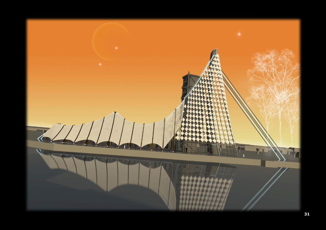
businesses among the educative status within the Heijplaat area as a medium for city marketing. Its design tries to
accomplish this effect by creating a visual impression of a beacon along the shoreline of the Nieuwe Maas and reconnecting
the area with it surroundings. The design concept is inspired by a spiders web and in addition the way how a cocoon like
lampion-flower (the Physalis Alkekengi) is build-up. This kind of material translates the visual appearances of weaving into
spatial relations based on a tensional setup throughout the building. A veil which covers the total ground floor has an open-
closed character and gives the ambience inside more the impression of a marketplace than a culture palace. A combination
in relief and transparency for creating the pattern which contains on one hand enough privacy and gives on the other hand a
reasonable amount of daylight. The futuristic appearance of the weaved building skin and its leveled anticlastic identity
which covers the space inside the building, creates a whole new meaning to the dynamic visual concept in relation to private
and public interaction. The aim is to use the museum of contemporary art to revitalize and re-energize the Heijplaat area
and by doing so creating a gateway between the village and modern society in Rotterdam. The building will not only
accommodate different kind of art collections, but will also be available for other functions within the region of creative
industry. Studios where artists can expand their creativity (sculpturing & painting). Workshops will be held to educate and
find the creativity within one another. Theater for displaying all sorts of media. And of course in addition: a cafeteria,
administrative offices, lounge areas, shopping and parking facilities.
The construction of the building is as much as possible accomplished by using steel and wood, positioned in such a way with
tension in mind. Also in addition the construction is faced outwards to emphasize the weaving-like appearance. The meshed
veil is being held up through the use of a stayed-cable system which is also used in the field of bridge building engineering.
The form of the stayed-cable system combined with a large concrete pylon (which maintains the stability of the building),
will characterize the overall appearance of the Suspended-Veil design.

7
▲ 002: reconnecting the Heijplaat area with its surrounding satellites

8
Rotterdam is a city which is dynamic in appearance and shaped over time. Due to the forces of the open water, the layout of
the city is forever linked to the complexity of the landscape. Looking at a higher scale level, this urbanized landscape
situated on the mouth of a big river (Nieuwe Maas), consists out of separate islands. Combined with other satellites such as
Rhoon, Schiedam and Pernis, they all have their own identity and in most cases lost the connection with the main inner city.
One of the islands is called Heijplaat and is situated between Pernis and the centre of Rotterdam. This harbor-like
environment played in the past a big role in the development of the economical situation of the province of South-Holland.
With the appearance of the Maasvlakte 1 in 2007 and Maasvlakte 2 in 2013 along the coast-line of the Netherlands, a large
amount of high industry is relocated towards this area. This resulted in a lower density of industry at areas which were well
known as “de stadshavens”. When paying a visit to the Heijplaat area we see a degraded overall appearance of industrial
quality with poorly connected underlying relations of the locality. Considering that this area should not be confused with a
high-end society with green environments, the appeal of the rough industry is characteristic for Rotterdam and also worth
mentioning as historical speaking a cultural significance for the old habitants; it even has lost its iconic value.
Reinvention of the industrial weave
The Heijplaat area consists out of finger-like islands, all with industrial material and abandoned facilities, with a central
residential area and a small green environment at Quarantine Island. The RDM site (Rotterdamsche Droogdok Maatschappij)
was formerly a ship building / repair yard and is now undergoing redevelopments into an area with educational purposes (a
school has recently been established in one of the warehouses) combined with business who are willing to help them with
innovative activities. With reference to transportation, the Heijplaat area is connected with one bus line service which has a
frequency of one per hour from and towards the centre of Rotterdam. In addition a ferry is transporting numerous students
from the north river-bed towards the RDM area and of course vice versa. Stimulating growth in new developments, attract
sophisticated residence, invest in recreation and creative activities, will lead to city marketing and economic impulse; it’s
time to place the Heijplaat area back on the map!

9
▲ 003: the Heijplaat area with its finger-like islands

10
▲ 004: new organization for the Heijplaat area

11
An attempt to enhance the quality of the Heijplaat area has been made into a master-plan in where Research, Design and
Manufacturing are essential topics. With a key-element to attract collaborating large offices with innovative activities that
will lead to new product marketing and services. Three zones are assigned which are available for expansions: the RDM area
with educative and innovative industries and the Quarantine Island for tourism and recreation purposes (page 10). One
important component which has to be added to the Heijplaat area for improving its accessibility and connecting all the zones
along the river is a transportation method called: the light-rail. The light-rail starts in the centre of Rotterdam and extents
all the way towards the Maasvlakte. This will increase the mobility of the community and reconnect the Heijplaat area with
the surrounding satellites.
How can we contribute to this ambition for increasing the prosperous status of the Heijplaat area with architecture?
One of the answers lies in an example in a city called Bilbao (Spain), where Frank O. Gehry made his design for a Museum
of Contemporary Art (Guggenheim) along the Nervion river. The city Bilbao, before the museum was build, faced the same
problem as this moment with the Heijplaat area. In the past it was an area with high industry which has lost its blooming
business and iconic value over time. With the revolutionary design of Frank O. Gehry, it attracted new offices and residences
and therefore (iconic-ally speaking) Bilbao contributed to the expansion of one of Spains metropolitan areas: the Comarca of
Greater Bilbao. Last year the architect Shiguru Ban unveiled his design of Museum of Contemporary Art in Metz (France).
With an inauguration by the President of France, Nicolas Sarkozy on May 12; 2010, they are hoping for the Bilbao effect and
therefore increasing the worthy status of Metz (page 12). The same can be applicable to the Heijplaat area: as a beacon
along the Nieuwe Maas collaborating with the already existing Museum Boijmans van Beuningen in the centre of Rotterdam.
A place that symbolizes the upcoming creative domain and convert the industrial roots of the RDM into a modern social
environment. A design that will not only give the Heijplaat area its demanding economic impulse, but also as a place well-
known to the habitants of Rotterdam together with a great focus on tourism.

12
▲ 005: a Museum of Contemporary Art should generate the demanded economic impulse for the Heijplaat area

13
The Quarantine island within the Heijplaat area has been defined in the master-plan as an island for recreation and tourism
purposes. It is a place with a huge contradiction in harbor activities and leisure capabilities. On one hand we see a business
with large vessel chains and anchorages and on the other hand there is a green environment, with large trees around 30
meters in height to indicate its border, pony’s, monumental buildings and above all a beach. It used to be a leisure or resting
place for seaman, but lost its existence over time and is now being occupied by squatters. This island has a tourist
attraction, but people in general might get disappointed by the industrial business and introvert character of the island. The
following text describes a new design for the Quarantine Island, extending its green environment, reversing the introvert
character into a more social coherent atmosphere and improving the culinary attraction.
▲ 006: a few impressions of the Quarantine Island: industrial material with a green environment
The goal of the Quarantine Island is to create a cultural domain with leisure in mind to accommodate the breeding place at
the RDM area; to attract new business and to help the RDM area to be notified in public relations. As can be seen on the
next page, the important element of the Quarantine Island is the light-rail. The light-rail situated above the ground, divides
the island in two sides. The north side will contain a catering industry with a large park and on the south side a zone which
has been left open for the Suspended Veil design. This zone has also been chosen for its visual orientations. When entering

14
▲ 007: arrangement of the Quarantine Island

15
the island you will notice on your left side the building first and not the light-rail. The catering industry is arranged in the
monumental area and will provide not only the island itself but also the museum of contemporary art for the demanded food
and drink supplies. To make the Island more coherent, industrial facilities are given place to a park-like area which is
connected to the already existing green environment; this results in a more extrovert character of the island. From the
entrance of the island a continuous boulevard along the shore-line has been placed to increase the accessibility towards the
beach. It consists of a bicycle path with small tree lines.
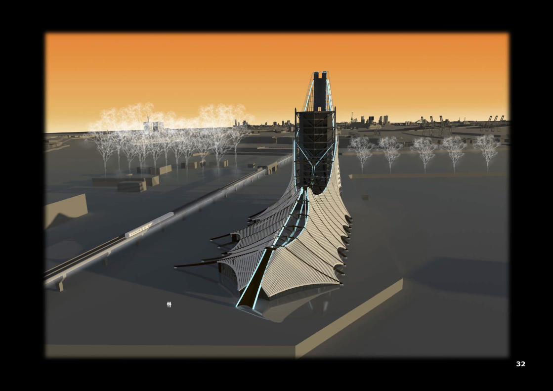
The Suspended-Veil design is placed parallel along the south shore-line of the island and should be recognized as a beacon
towards the sea-outlet. The light-rail is the first weaving line at which new elements evolve. However the building itself is
related to this line, but is not connected or emphasized as a part of the light-rail. At a higher scale level the building can be
seen as a cocoon which originate from the light-rail. Think about how the way a butterfly evolves over time and abandon its
origins. The building itself is an autonomous object which growths and extents on the area of the Quarantine Island with
respect to the light-rail. The size and shape of the plan-layout of the building is created through urban weaving. A spider
starts by creating his web with horizontal outside wires together with the influences of the wind and pure luck. When the
horizontal wires are firmly secured at the other end, a vertical wire is pulled down and creates the first three radials of the
web. After that, the spider creates a centre by adding spokes and one continuous spiral wire which is characteristic.
The contour-lines of the Quarantine Island are the first horizontal lines in where a web can be spun. Spokes are drawn from
one corner to another as can been seen on the next page. These lines are indicated as guide lines in where the plan-layout
of the building will be created. The already designated zone and the position of the light-rail will eventually given shape and
size to the Suspended-Veil plan-layout.
constructing a spider-web: 008 ►

16
▲ 009: these lines will formulate the shape and size of the plan-layout and acts as guide lines
On the picture mentioned above, the border lines of the Quarantine Island acts as the first weaving-lines of the spiders-web.
Within these border lines spokes are drawn from one corner to another, creating the step towards a plan-layout for the
design; the purpose of these lines are to act purely as guide lines.
17
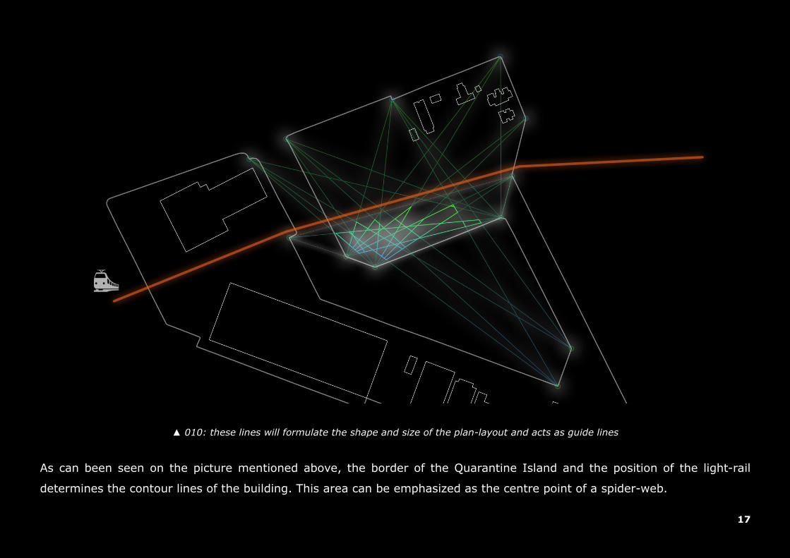
▲ 010: these lines will formulate the shape and size of the plan-layout and acts as guide lines
As can been seen on the picture mentioned above, the border of the Quarantine Island and the position of the light-rail
determines the contour lines of the building. This area can be emphasized as the centre point of a spider-web.

18
The Suspended-Veil design is derived from the inspiration of a spiders-cocoon in combination with a lampion flower (the
Physalis Alkekengi). The principle of the design has been formulated by interpretating the way on how these elements of
nature are build, the purpose and meaning of their different layers, how the inner climate is regulated and how they behave
in their environment. The question is raised: what breaks down first? By categorizing the degradation process and translate
these processes into architectural and engineering understanding, the first principles have been made and forms the
underlying basis towards a design; with weaving as the main theme. A cocoon is a lively shelter that protects and supports
the precious cargo inside. A combination in relief and transparency of the shell that maintains on one hand enough privacy
and controls on the other hand a reasonable amount of daylight. This open-closed character of the skin visualizes this effect
by creating the impressions of what is on the outside doesn't seem to be on the inside. Through the use of different
components in a layered structure the building gets a stubborn but alluring characteristic. The ambition is to use this
package for creating a meshed building-skin which covers the total ground floor and protects the art-collection within; all
will emphasize a whole new meaning to its dynamic concept in relation to private and public interaction.
Likeness that symbolizes something
▲ 011: a spider with a cocoon underneath ▲ 012: the lampion flower: Physalis Alkekengi

19
The picture mentioned to the right indicates the different
categories of what breaks down first related to the lampion
flower. The Physalis Alkekengi consists out of a starting-
root (from where all the other components evolves), a
crest, veins and cells, and a filling for creating a closed
shelter. Structural speaking, the flower is actually a dome-
like shelter which consists out of a series of arches (veins)
with a straining trap (crest) at the bottom for preventing
deformations. In addition dome-like structures have
almost no bending moments near the supports and overall
can be made thinner than other structures without
endangering the stability.
“Once the behavior of a cable is
grasped, one easily realizes that an
arch is nothing but an upside-down
cable. Imagine flipping a loaded
cable over after freezing it in its
curved shape. The cable becomes an arch. The pull (or
tension) in the cable becomes a push (or compression) in
the arch, and the outward thrusts on the cable become the
inward thrust on the arch, which prevent it from opening up.” 01
▲ 013: the lampion flower: what breaks down first?

20
In contrary to domes, weaves normally have components which are mounted under tension. They can be found almost
everywhere you look: t-shirts, Oak Processionary, a plan-layout of any given building, veins and nerves of a human body,
etc. However, consider that weaves are always 1D or 2D members it is therefore very difficult to make a 3D weave–like
building. A building made out of a steel construction is not a 3D weave, but consists out of 1D beams and 1D columns. As
we all know, lines and faces are the main components for making a 3D shelter. Within architecture, weaves are usually
described as membrane-like structures which consists out of a 2D textile material.
These lightweight structures are elegant in their appearance and owe their shape to
tension. A single cable or wire doesn’t have a shape of its own. It cannot sustain
compression and when it is thrown away onto a single surface, it just takes a free-
form appearance; which is different over and over again by repeating the same
method. Only when a tensional force is applied onto the cable or it has been fixed
at two points, then the cable takes the desired shape. ▲ 014: build with tension
Another important factor that needs to be considered is that all buildings with a tensional setup, categorized into: Fixed,
Suspended, Pneumatic, Anticlastic and Cable-truss, they are all vulnerable to wind. The cables or membranes within these
buildings should be fixed under the right amount of tension without damaging the material, and be strong enough to
prevent it from buckling due to wind-loads. This problem can be solved in three different ways: by adding weight for holding
down the cable, adding a secondary cable parallel and in the opposite way to retain the shape and resists upward loads or
by using a material other then steel which can bare tensional forces and is sustainable to buckling (such as timber).
There are a lot of buildings with a tensional setup, but are usually build with a steel cable space-net or with textile
membranes. However, most of these buildings are open or can’t be described as one with a closed shelter. One architect
who is famous for his buildings based on tension is Frei Otto. He made in 1967 a German pavilion for the exposition in
Montreal; Canada, which was broken down several years later. Until this moment such building hasn’t been rebuild.

21
Quote:
fear of the unknown
they are afraid of new ideas
they are loaded with prejudices, not based upon anything in reality but based on if something is new
I reject it immediately because it frightening me
what they do instead, is just stay with the familiar
you know, to me the most beautiful things in all the universe, are the most mysterious
Unquote
“from: Wayne Dyer”

22

23
The design idea of the Suspended-Veil project is coming from the urban vision for reconnecting the Heijplaat area with its
surrounding satellites; as can be seen on page 7. These beams of lights are projected down towards the location of the
Quarantine Island. The spot at where these beams meet each other above the island is the exact spot at where the root of
the building starts and expands further down into two different weaving concepts. These weaving concepts emphasizes the
overall appearance of the building, at which one is delicate (open and light-weighted) and the other one is harsh (more
closed and uses more material). Except for the difference in the way how these two separate kinds of weaving concepts or
facades are formulated, they should act as one building skin. Their seams in combination with its leveled identity should be
created in such a way that a smooth transition denotes synergy.
Idea, Starting-Points and Instruments
▲ 015: beacon along the shoreline of the Nieuwe Maas ▲ 016: two different weaving concepts
The building-skin which is made out of the two weaving-like facades, can be described as a veil which covers the total
ground floor. A large tower or pylon is created for maintaining the stability of the building and for holding up the veil.

24
A mesh or veil is a 2D surface which consists out of a weaving pattern.
Looking at a more detailed level you’ll see that this weaving pattern is
actually a basic grid created by cross-over linked horizontal and vertical
lines. The theme of the design is based on the manipulation manner of
these line trajectories. The path of the line trajectories can be manipulated in
such a way that the density of the mesh is less at a few places (with higher
density at their sides), which opens up the mesh and creates a new visual
interaction between both sides of the mesh. The tower of the building acts as
an interference within the meshed veil, but also creates a spatial relation
between the two weaving concepts.
The structural consistency of the mesh cannot be found somewhere close
within its boundaries, but in its constraints. If the mesh is not formed in the
right way and isn’t placed under the right amount of tension force,
distortions of the line trajectories can occur and the meshed veil is
vulnerable to any given load; even to gravity.
The structural components (line-trajectories) of the veil should be fixed
individually at both ends, each with their own purpose in controlling the
stability of the veil. A woven textile, consists out of a severe amount of
wires, is only fixed at its corners. A lot of wires at the middle are structural
speaking useless. A secondary component (usually a compression member)
should be placed at the border of the mesh for tensionizing all the wires.
▲ 017: joining the two facades together
▲ 018: manipulation of wire trajectories

25
▲ 019: a first design scheme
The picture mentioned above is the first design scheme that has been made. A root at the top unfolds itself downwards into
two different kind of weaving-like façades; each with their own identity and structural appearance. This scheme forms the
underlying basis towards a building with an anticlastic or suspended representation and generates remote visualization
between the inside and public surroundings.
delicate (open and light) harsh (more closed and more material )

26
▲ 020: few of the design instruments
The pictures mentioned above are just a few of the design instruments; all with a function on how the weaves of the veil
behaves compared to the spatial content of the building. The density of the weaves does not only controls the visibility
between the public and private space, but also regulates the amount of light that will be transmitted through the veil. In
addition, a setup of different distances will generate a different kind of leveled information in the buildings expression.
27
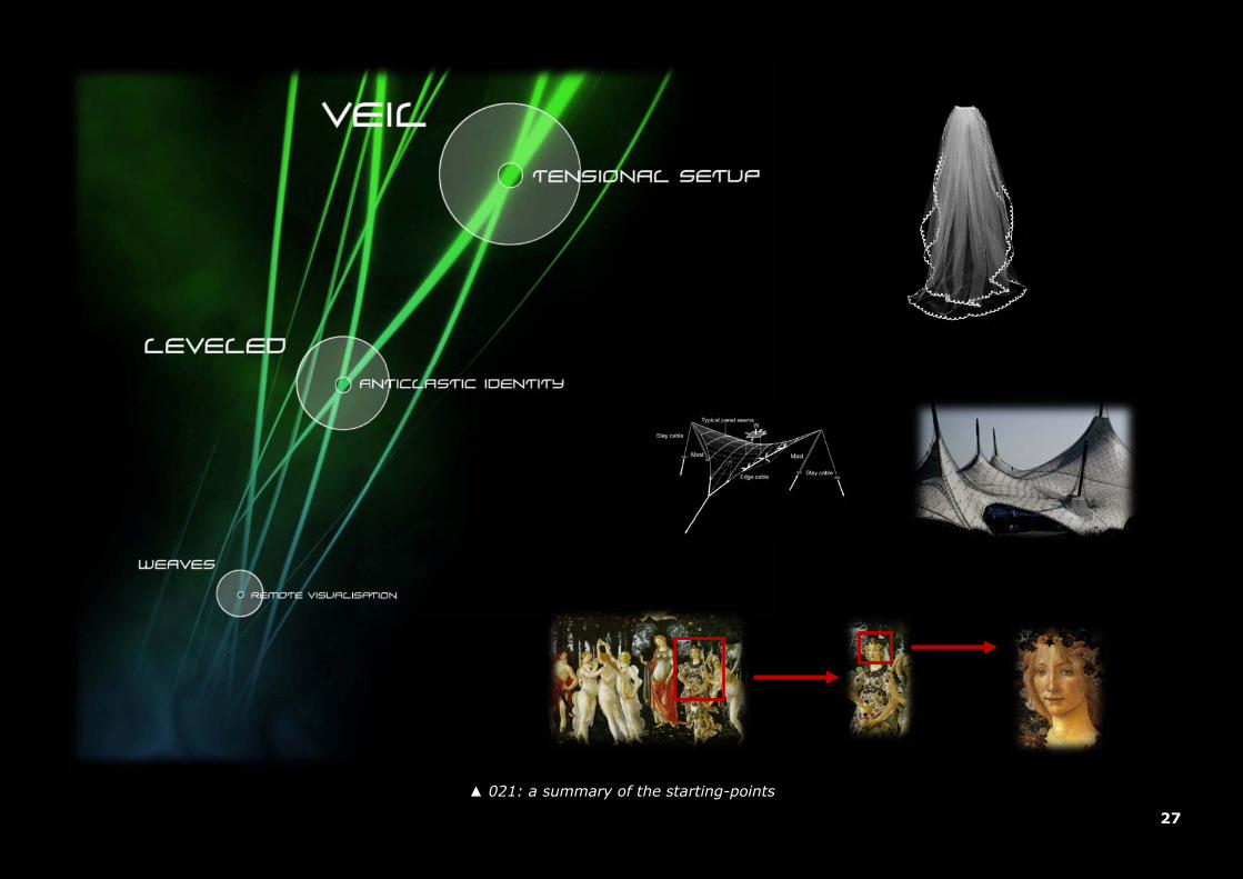
▲ 021: a summary of the starting-points

28
The design of the Suspended-Veil project is derived from three main categories: a veil which is structurally buildup by the
use of tensional forces and covers the total inner spatial content, an overall appearance of the building which has a leveled
anticlastic (a surface curved in both directions) identity and a weaved façade structure that emphasizes the difference in
remote visualization.
The meshed Veil consists out of two different types of weaved facades and is buildup by the use of materials which are
suitable for sustaining tensional forces (wood and steel). A large pylon, like as one man can find in bridge building
engineering, is placed in front of the tower nearby the entrance, for maintain the stability of the building and for holding up
the meshed veil. The most important weaving-line of the meshed veil is the “bridge wire” which is connected on one end at
the top of the pylon and the other end is connected to a pedestal at ground level. This continuous wire is described as a
stayed-cable system and acts as the lifeline of the building. Both of the two weaved facades are attached to the stayed-
cable system. Additional pillars or masts are placed inside the hall for supporting the stayed-cable system. In addition, they
also accentuate the appearance of tent-like structures (anticlastic).
Both of the weaved facades are buildup in different layers of material and size. Their density contribute to the effect of
changing visualization and light transmission during the day. Looking at these facades from a distance, a different
expression of the building appearance can be noticed in contrary to a shorter distance. Coming more closer towards the
building the different layers of the weaved facades will provide new information in terms of visualization. The harsh weaved
façade is created in such a way that a translucent – closed pattern will create a dynamic ambiance of sunlight and shade
projected down onto the floors inside the major hall. In addition, from one point of view inside the major hall the
perspective of the weaved structure changes by walking along the path of the promenade deck; this because of the curved
shape of tent-like weaved façade.

29
▲ 022: three different categories of weaving
The picture mentioned above shows the different categorization of weaves which are used in the Suspended-Veil design. A
functional weave for the plan-layout of the building, a structural weave for the construction which is buildup through
separate components acting as one, and a decorative weave for the overall appearance.
tensional setup
segmented
construction
motion
through
weaves

30
31
32

33

34
35

36
37

38
39

40
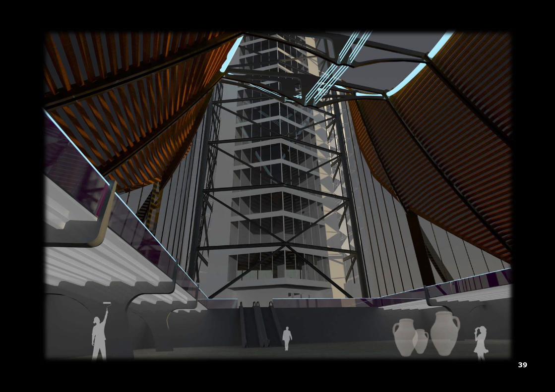
The following text will describe the construction of the Suspended-Veil design. Pictures are made to show
the reader one step at a time how the construction is buildup. With each picture new information is
provided about the content; some with a few references.
Hanging on a stayed-cable system (construction)
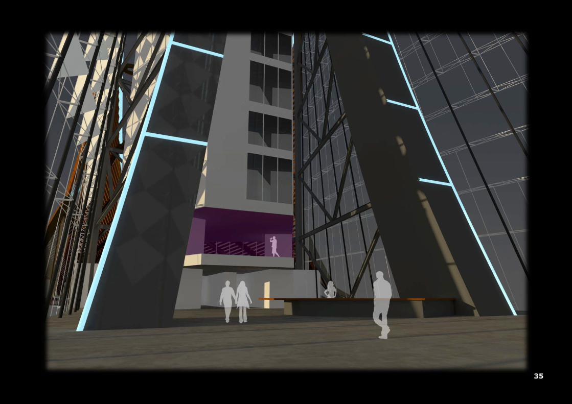
01: The picture to the right indicates the large pylon
. The pylon is made out of large concrete segments
which are hull and pre-tensioned to act as one object. The pylon consists out of two feet’s which are
close together near the top and separates while moving towards the ground; it indicates the root which
starts at the top (as described on page 23). Not only provides the pylon the necessary stability of the
building, but also because its height (99 meters), it is a large object which is heavy in the expression of
the building. Therefore the quality of the concrete should be as smooth as possible.
02: The picture to the left shows the outside construction of the tower which is connected at the large
pylon. However the construction is inside the thermal layer of the veil, even it is outside the volume of
the tower; this has been done to express the structural weave. The construction of the tower consists
out of steel beams and columns which are described as chevrons
The way how the chevrons are created can be related to the Malietower in Den Hague.
Both have the construction outside the volume, on either side the steel columns are
placed under an angle to coop the tensional forces that can occur due to the frontal
forces (as can be seen on page 47).
.
Malietower; Den Hague: 023 ►

41
Bridge Kanne; Belgium: 025 ▲
03: The pictures above show the Freyssinet stayed-cable system with two additional columns for holding up the cables.
They consist out of two cables which are mounted at one end at the top of the large pylon and the other end is mounted at
a pedestal at ground-level. The two continuous cables are supported by two steel masts which are placed in the middle; one
with a height of 30 meters and the other one with a height of 15 meters. Because of the hanging property of the stayed-
cable system, they also support the idea of the curved roof of the tent-like structure (anticlastic). Because the cables are
continuous, the columns almost do not possess any bending moment near their support. The stayed-cable system consists
out of multiple Monostand cables which are threaded through steel segmented casings, just like the ones which are just at
the Kanne Bridge in Belgium. At the back of the large pylon, an additional cable-system has been applied for providing
structural equilibrium.
▲ 024: Monostrand cables
42
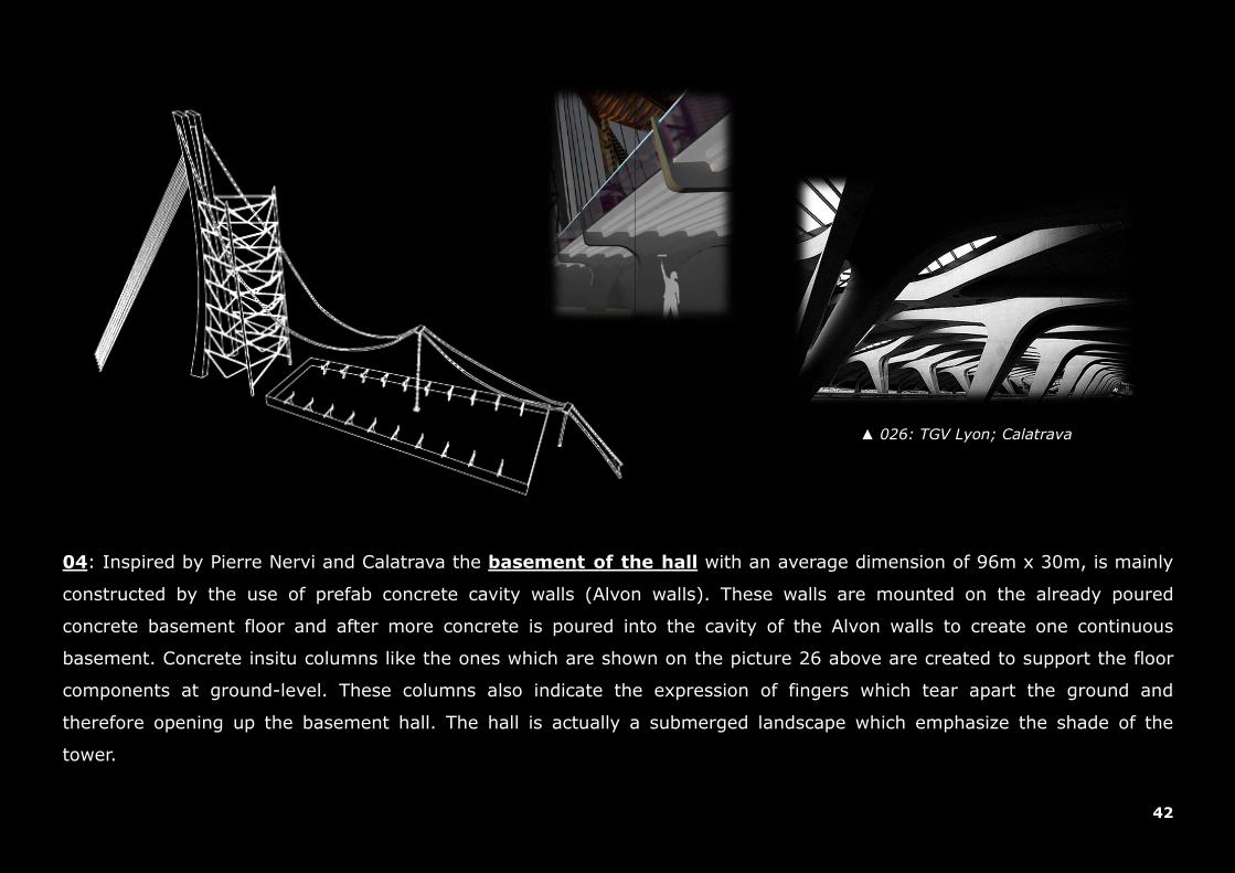
04: Inspired by Pierre Nervi and Calatrava the basement of the hall
with an average dimension of 96m x 30m, is mainly
constructed by the use of prefab concrete cavity walls (Alvon walls). These walls are mounted on the already poured
concrete basement floor and after more concrete is poured into the cavity of the Alvon walls to create one continuous
basement. Concrete insitu columns like the ones which are shown on the picture 26 above are created to support the floor
components at ground-level. These columns also indicate the expression of fingers which tear apart the ground and
therefore opening up the basement hall. The hall is actually a submerged landscape which emphasize the shade of the
tower.
▲ 026: TGV Lyon; Calatrava
43
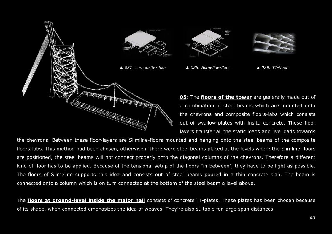
05: The floors of the tower
are generally made out of
a combination of steel beams which are mounted onto
the chevrons and composite floors-labs which consists
out of swallow-plates with insitu concrete. These floor
layers transfer all the static loads and live loads towards
the chevrons. Between these floor-layers are Slimline-floors mounted and hanging onto the steel beams of the composite
floors-labs. This method had been chosen, otherwise if there were steel beams placed at the levels where the Slimline-floors
are positioned, the steel beams will not connect properly onto the diagonal columns of the chevrons. Therefore a different
kind of floor has to be applied. Because of the tensional setup of the floors “in between”, they have to be light as possible.
The floors of Slimeline supports this idea and consists out of steel beams poured in a thin concrete slab. The beam is
connected onto a column which is on turn connected at the bottom of the steel beam a level above.
The floors at ground-level inside the major hall consists of concrete TT-plates. These plates has been chosen because
of its shape, when connected emphasizes the idea of weaves. They’re also suitable for large span distances.
▲ 027: composite-floor ▲ 028: Slimeline-floor ▲ 029: TT-floor

44
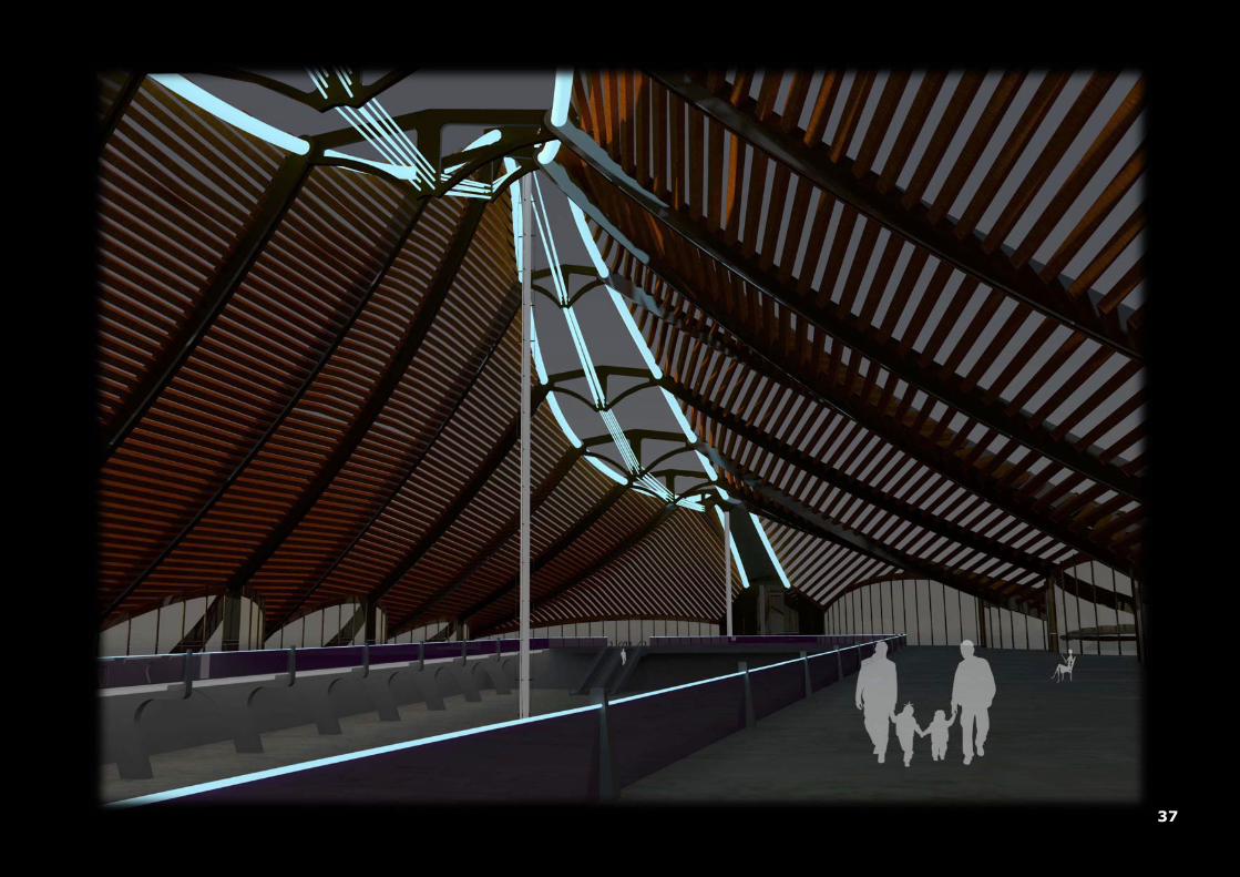
06: Perpendicular to the stayed-cable system, arches
are mounted and consists mainly out of timber. These
suspended arches are the main construction components of the harsh weaved façade and hold down the stayed-cable
system in the right position. Timber has been chosen because it resists buckling due to wind-forces. In contrary to steel
cables which are more vulnerable to wind-loads, additional supports had to be created for increasing the stability of the
façade; by using timber these additional supports can be neglected. Timber has also an excellent property for sustaining
tensional loads, as can be seen at the Solebad in Bad Durrheim (Germany). A suspended shell totally made out of timber!
These arches are in same-line as the concrete fingers at basement-level and creates a kind of portal construction. The
portals are placed in such a way that they are reproducible but all with differences in dimensions.
▼ 031: Solebad, Bad Durrheim, 1987, Geier & Geier
▲ 030: Solebad, Bad Durrheim, 1987, Geier & Geier

45
07: Around the promenade deck a wooden knocked-down (montage-kozijn) glass façade
has been placed. This façade
provides the necessary escape exits and prevents unwanted visitors from climbing onto the roof of the major hall. The glass
façade follows the curved contour lines of the plan-layout and is connected at the top to a laminated beam, which on-turn is
mounted between the suspended timber arches.

46
08
The structure of the Shroud façade consists mainly of laminated timber connected between the suspended arches. On top
of the laminated beams a roof-line system is placed horizontally, this creates continuous lines which on-turn emphasizes the
idea of weaves. On top of the line-roof system a meshed steel-plate are partially mounted and emphasizes the appearance
of opened curtains (as can be seen on page 30).
: The main structure of the Cervolant façade consist of multiple steel anchorage forks which are connected at the
bottom to the ground and at the top to the stayed-cable system. A combination of horizontal beams, multiple Halfen tie-
rods (connected at the top to the stayed-cable system and at the side to the anchorage forks) and glass panels creates the
weaved façade of the Cervolante. This method of façade creates an open-like character and is light-weighted in appearance.
the Cervolante: delicate
the Shroud: harsh
▲ 033: Kalzip roof-line system
◄ 032: Halfen-Detan system
47
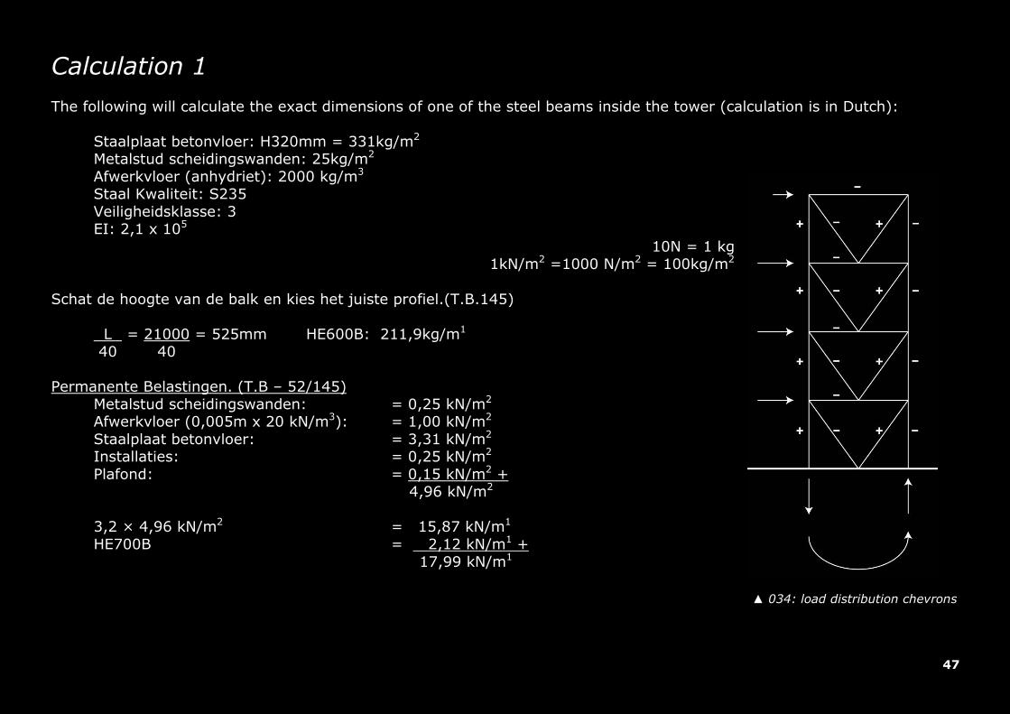
Calculation 1 The following will calculate the exact dimensions of one of the steel beams inside the tower (calculation is in Dutch):
Staalplaat betonvloer: H320mm = 331kg/m2 Metalstud scheidingswanden: 25kg/m2 Afwerkvloer (anhydriet): 2000 kg/m3 Staal Kwaliteit: S235 Veiligheidsklasse: 3 EI: 2,1 x 10⁵
10N = 1 kg 1kN/m2 =1000 N/m2 = 100kg/m2
Schat de hoogte van de balk en kies het juiste profiel.(T.B.145)
L = 21000 = 525mm HE600B: 211,9kg/m1 40 40
Permanente Belastingen. (T.B – 52/145)
Metalstud scheidingswanden: = 0,25 kN/m2 Afwerkvloer (0,005m x 20 kN/m3): = 1,00 kN/m2 Staalplaat betonvloer: = 3,31 kN/m2 Installaties: = 0,25 kN/m2 Plafond: = 0,15 kN/m2 +
4,96 kN/m2
3,2 × 4,96 kN/m2 = 15,87 kN/m1 HE700B = 2,12 kN/m1 +
17,99 kN/m1
▲ 034: load distribution chevrons

48
Veranderlijke belastingen. (T.B – 55) (Personen, meubilair en aankleding) Kantoor = 3,0 kN/m2; Factor = 0,25
3,2 × 3 kN/m2 = 9,6 kN/m1 UGT.
qd = 1,2 x 18 + 1,5 x 9,6 =36,0 kN/m1
BGT.
qrep = 18 + 9,6 = 27,6 kN/m1 Dwarskracht
vz;s;d = < 1 vz;u;d vz;s;d = 0,5 x q x l = 0,5 x 36,0 x 21 = 378 kN vz;s;d = 378x103 = 0,37 < 1,0 O.K! 0,58 (h-2 x tf) x tw x fy;d 0,58 x (600-2 x 30) x 15,5 x 235
Moment
Iy= 171041x104 mm4; Wy;el = 5701x103 mm3 Moment = 0,125 x 36,0 x 212
= 1984,5 kNm

49
my;s;d = < 1 my;u;d my;s;d = 1984,5x106 = 1,48 > 1,0 [ N.O.K! ] Kies een ander profiel! wy;el x fy;d 5701x103 x 235
Bereken W en I benodigd?
W;benodigd = moment = 1984,5 =8444,7x103 mm3 fy;d/1000 235/1000 Doorbuigingsfactor over twee steunpunten: 6,2 I;benodigd = 6,2 x qrep x overspanning3 = 6,2 x 27,6 x 213 = 79.2371x104 mm4 0,002x1000 0,002x1000
Kies profiel:
HE700B Iy= 359.084x104 mm4; Wy;el = 8977x103 mm3 my;s;d = 1984,5x106 = 0,94 < 1,0 O.K. wy;el x fy;d 8977x103 x 235
Optredende doorbuiging (vervorming).
U = 5 x q x l4__= 5 x 27,6 x (21000)4 = 82,68mm < 84,0mm (0,004x21000) O.K! 384 x E x I 384 x 2,1x105 x 359.084 x 104
50
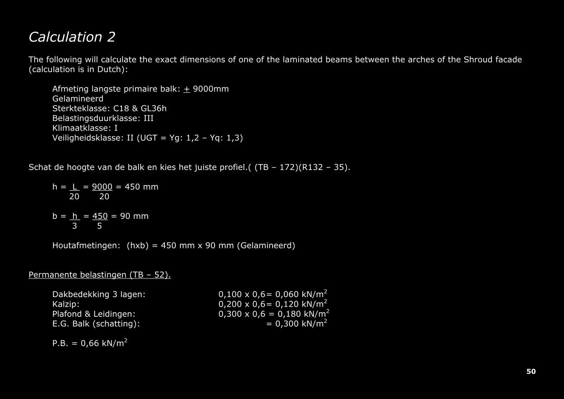
Calculation 2 The following will calculate the exact dimensions of one of the laminated beams between the arches of the Shroud facade (calculation is in Dutch):
Afmeting langste primaire balk: + 9000mm Gelamineerd Sterkteklasse: C18 & GL36h Belastingsduurklasse: III Klimaatklasse: I Veiligheidsklasse: II (UGT = Yg: 1,2 – Yq: 1,3)
Schat de hoogte van de balk en kies het juiste profiel.( (TB – 172)(R132 – 35).
h = L = 9000 = 450 mm 20 20 b = h = 450 = 90 mm 3 5 Houtafmetingen: (hxb) = 450 mm x 90 mm (Gelamineerd)
Permanente belastingen (TB – 52).
Dakbedekking 3 lagen: 0,100 x 0,6 = 0,060 kN/m2 Kalzip: 0,200 x 0,6 = 0,120 kN/m2 Plafond & Leidingen: 0,300 x 0,6 = 0,180 kN/m2 E.G. Balk (schatting): = 0,300 kN/m2 P.B. = 0,66 kN/m2
51
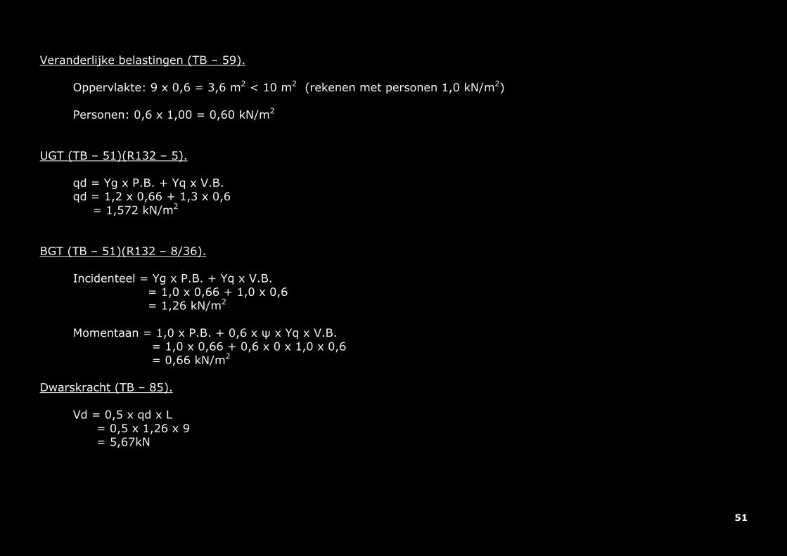
Veranderlijke belastingen (TB – 59).
Oppervlakte: 9 x 0,6 = 3,6 m2 < 10 m2 (rekenen met personen 1,0 kN/m2) Personen: 0,6 x 1,00 = 0,60 kN/m2
UGT (TB – 51)(R132 – 5). qd = Yg x P.B. + Yq x V.B. qd = 1,2 x 0,66 + 1,3 x 0,6 = 1,572 kN/m2
BGT (TB – 51)(R132 – 8/36).
Incidenteel = Yg x P.B. + Yq x V.B. = 1,0 x 0,66 + 1,0 x 0,6 = 1,26 kN/m2 Momentaan = 1,0 x P.B. + 0,6 x ψ x Yq x V.B. = 1,0 x 0,66 + 0,6 x 0 x 1,0 x 0,6 = 0,66 kN/m2
Dwarskracht (TB – 85).
Vd = 0,5 x qd x L = 0,5 x 1,26 x 9 = 5,67kN

52
Moment (TB – 85).
Md = 1/8 x qd x L2 = 0,125 x 1,26 x 92
= 12,75 kNm Controle buigspanning (R132 – 38/39). Bepaling uiterst opneembare spanning:
Fm;o;rep = 36 N/mm2 Kmod = 0,85 Fm;o;d = Fm;o;rep x Kmod x Kh = 36 x 0,85 x 1 = 25,5 N/mm2 Ym 1,2
Bepaling maximaal optredende buigspanning:
σm;o;d = Md = 12,75x10⁶_ _= 4,2 N/mm2 Wy (1/6)x90x4502 Controle = 4,2 = 0,16 > 1,0 O.K! 25,5
Controle afschuiving (R132 – 38/39). Bepaling uiterst opneembare schuifspanning:
Fv;o;rep = 4,3 N/mm2 Kmod = 0,85 Fv;o;d = Fv;o;rep x Kmod = 4,3 x 0,85 = 3,26 N/mm2 Ym 1,2

53
Bepaling optredende schuifspanning:
σv;o;d = 1,5 x Vd = 1,5 x 5,76x103 = 0,14 N/mm2 A 90x450 Controle = 0,14 = 0,04 < 1,0 O.K! 3,26
Controle Doorbuiging (TB – 172)(R132 – 43). Bepaling optredende doorbuiging:
Ed = _Erep x Kmod = _ 9000x 1 = 900 (Ukort) Ym x (1 + ψkr) 1 x (1 + 0) Ed = _Erep x Kmod = _ 9000x 1 = 4500 (Ulang) Ym x (1 + ψkr) 1 x (1 + 1) Ukort = 5 x q x L4 __= 5 x (1,26-0,66) x (9000)4_ ___ = 8,33 mm 384 x Ed x Iy 384 x 9000 x (1/12 x 90 x 4503) Ulang = 5 x q x L4 __= 5 x 0,66 x (9000)4_ ___ = 18,33 mm 384 x Ed x Iy 384 x 4500 x (1/12 x 90 x 4503) Utot = Ulang + Ukort = 18,33 + 8,33 = 26,66 < 36 (0,004 x 9000) O.K!
54
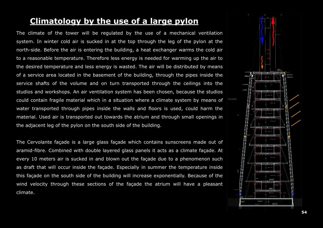
The climate of the tower will be regulated by the use of a mechanical ventilation
system. In winter cold air is sucked in at the top through the leg of the pylon at the
north-side. Before the air is entering the building, a heat exchanger warms the cold air
to a reasonable temperature. Therefore less energy is needed for warming up the air to
the desired temperature and less energy is wasted. The air will be distributed by means
of a service area located in the basement of the building, through the pipes inside the
service shafts of the volume and on turn transported through the ceilings into the
studios and workshops. An air ventilation system has been chosen, because the studios
could contain fragile material which in a situation where a climate system by means of
water transported through pipes inside the walls and floors is used, could harm the
material. Used air is transported out towards the atrium and through small openings in
the adjacent leg of the pylon on the south side of the building.
Climatology by the use of a large pylon
The Cervolante façade is a large glass façade which contains sunscreens made out of
aramid-fibre. Combined with double layered glass panels it acts as a climate façade. At
every 10 meters air is sucked in and blown out the façade due to a phenomenon such
as draft that will occur inside the façade. Especially in summer the temperature inside
this façade on the south side of the building will increase exponentially. Because of the
wind velocity through these sections of the façade the atrium will have a pleasant
climate.
55
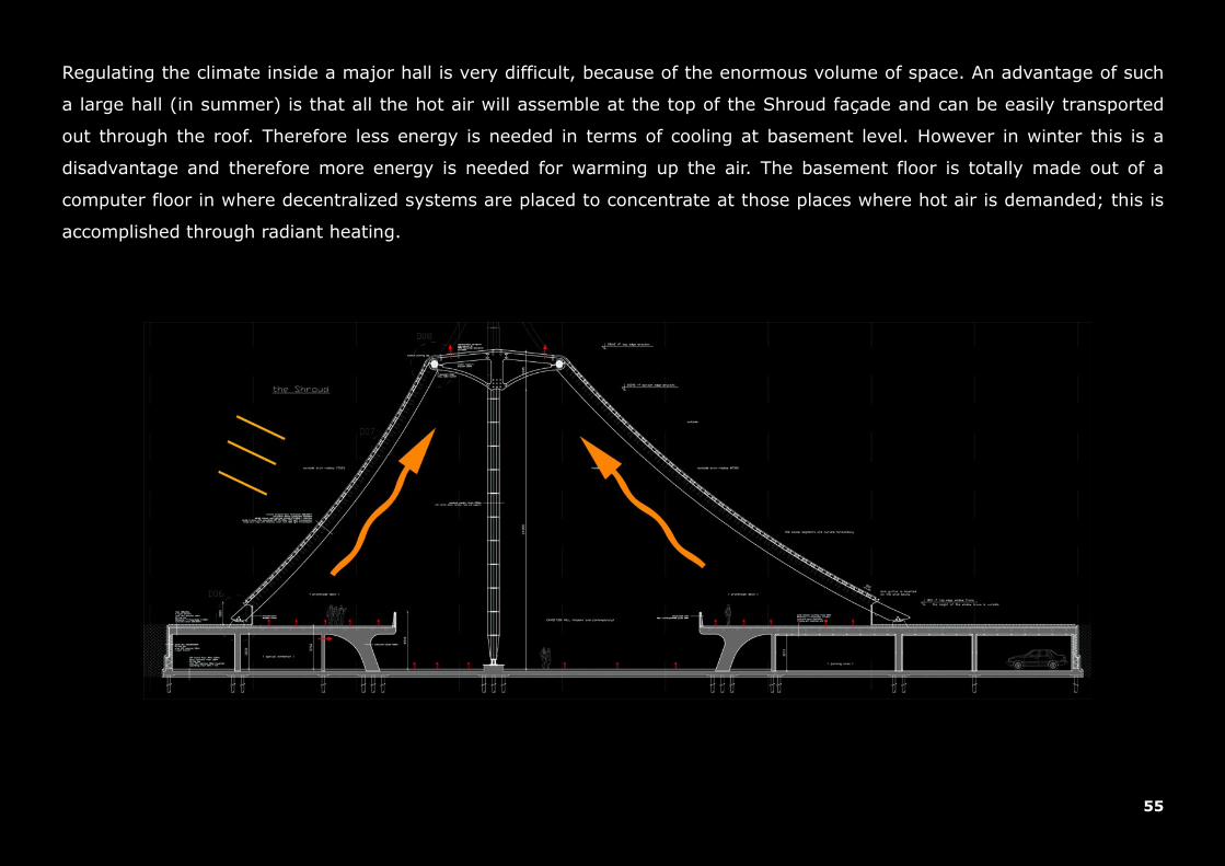
Regulating the climate inside a major hall is very difficult, because of the enormous volume of space. An advantage of such
a large hall (in summer) is that all the hot air will assemble at the top of the Shroud façade and can be easily transported
out through the roof. Therefore less energy is needed in terms of cooling at basement level. However in winter this is a
disadvantage and therefore more energy is needed for warming up the air. The basement floor is totally made out of a
computer floor in where decentralized systems are placed to concentrate at those places where hot air is demanded; this is
accomplished through radiant heating.
56
De design of the Suspended-Veil project is developed mainly by looking at different precedents, how they are formed and
how they control the tensional loads. The structural systems which are used in the design can be more or less related to
these precedents. Because this design has an impression which is on the edge of reality, the precedents should support the
decisions which have been made for the construction. The appearance of the Veil has the impression of a tent-like structure,
however tent-like structures behave differently. They consists out of surfaces with an anticlastic setup, curved in both
directions. Because of this setup the membrane surfaces can be made thin whatever possible while maintaining large span
distances. Their curvature has been demonstrated by the architect Frei Otto many times by the example of soap bubbles.
The Shroud façade which covers the major hall is also curved, but is not constructed with a anticlastic setup. From the other
angle the most part of the veil was buildup with the use of steel cables and a textile material, instead large laminated timber
beams are used. Still with respect to tent structures the Shroud façade is formed in such a way just like holding up a piece
of cloth into the air but still connected at some points onto the ground. This creates the different curvatures which on-turn
emphasizes tents structures.
Discussion

57
Weaves come in many forms, some are literally taken, others have to been seen with a sense of fantasy. The weaves which
are used in the design of the Suspended-Veil project are at one side thin steel wires and at the other thick timber laminated
beams. Both are connected by a seam which emphasize the difference between the two but also their relation as a part of
the whole; this is described as the veil. Iconographical of the design is the way how the inner world changes by means of
sunlight. The dynamic behavior of the shades projected down onto the basement floor of the major hall, where the art is
exhibited, creates new visual impressions. The size, pattern, translucent vs closed, the curvature of the weaves, all
contribute to this idea.
Conclusion
Looking back to my graduation year, Im by enlarge happy with the result of the design. I say by enlarge happy, because
from my own opinion the schemes could be improved. Also the fact that I started designing somewhere in the end of
December 2010, challenged me to work harder and therefore a lot have been investigated and looked into in a short amount
of time to make the Suspended-Veil as it is now. Maybe it has also to do with the fact that I wanted to create something
amazing, but trying to do this is almost the same thing like never being satisfied with the things you have.
Afterword
Many thanks to Jan Engels and Frank Schnater for their support and that their believe in me till the end!
58
Literature
Books:
Abbott, Edwin A. Flatland: A Romance of Many Dimensions. Princeton University Press, 2005. England. Bechthold, Martin. Innovative Surface Structures: Technologies and Applications. Taylor & Francis, 2008. 2 Park Square, Milton Park, Abingdon, Oxon OX14 4RN, England. Bahamon, Alejandro. The Magic Of Tents: Transforming Space. HarperCollins Design International and LOFT Publications, 2004. 10 East 53rd Street, New York, NY 10022, USA. Berg, Maritz van den. Soft Canopies: Detail in Building. Academy Group LTD, 1996. 42 Leinster Gardens, London W2 3AN, Members of the VCH Publishing Group, England. Berger, Horst. Light Structures – Structures of Light: The Art and Engineering of Tensile Architecture. Birkhauser – Publishers for Architecture, 1996; P.O.Box 133, CH-4010 Basel, Switzerland. Burg, L. van den. Stolk, Egbert. Urban Analysis Guidebook: Typomorphology. Technical University Delft, 2004. Faculty of Architecture. Department of Urbanism. Eekhout, Mick. Architectures in Space Structures. Uitgeverij 010 Publishers, 1989. Rotterdam. Isenberg, Cyril. The Science of Soap Films and Soap Bubbles. Tieto Ltd, 1978. Elton Road 5, Clevedon, Avon BS21 7RA, England. Jeska, Simone. Transparent Plastics: Design and Technology. Birkhauser – Publishers for Architecture, 2008; P.O.Box 133, CH-4010 Basel, Switzerland. Kaltenbach, Frank. Detail Practice: Translucent Materials: Glass, Synthetic Plastics, Metals. Birkhauser – Publishers for Architecture, 2004; P.O.Box 133, CH-4010 Basel, Switzerland.
59
Knaack, Ulrich. Klein, Tillmann. Bilow, Marcel. Auer, Thomas. Facades: Principles of Construction. Birkhauser – Publishers for Architecture, 2007; P.O.Box 133, CH-4010 Basel, Switzerland. Marotta, Antonello. Contemporary Museums. Skira Editore S.p.A, 2010. Palazzo Casati Stampa via Torino 61, 20123 Milano, Italy. Muller, Christian. Holzleimbau: Laminated Timber Construction. Birkhauser – Publishers for Architecture, 2000; P.O.Box 133, CH-4010 Basel, Switzerland. Ruske, Wolfgang. Timber Construction: for Trade, Industry, Administration: Basics and Projects. Birkhauser – Publishers for Architecture, 2004; P.O.Box 133, CH-4010 Basel, Switzerland. Salvadori, Mario. Why buildings stand up: the strength of architecture. W. W. Norton & Company Inc, 2002; 500 Fifth Avenue, New York, NY 10110, USA. Schlaich, Jorg. Bergermann, Rudolf. Leicht Weit / Light Structures. Prestel Verlag, 2003. Koningsstrasse 9, 80539, Munich, Germany. Seidel, Michael. Tensile Surface Structures: A Practical Guide To Cable and Membrane Construction: Materials, Design, Assembly and Erection. Ernst & Sohn Verlag für Architektur und technische, 2009. Wissenschaften GmbH & Co. KG, Berlin, Germany. Vidarte, Juan Ignacio. Bruggen, Coosje Van. Gehry, Frank. Frank O. Gehry: Guggenheim Museum Bilbao. Guggenheim Museum Publications, 1997. New York, USA. Zerning, John. Design Guide To Anticlastic Structures In Plastic. Polytechnic of Central London, 1975.

60
Technical Documents:
Alvon walls: http://www.alvon.nl TT-plates: http://www.betonson.com Raised Floors: http://www.cepnl.com Bubbledeck floors: http://www.bubbledeck.com Swallow Composite floors: http://www.dutchengineering.nl Kalzip systems: http://www.kalzip.com Rockfon Ceiling: http://www.rockfon.nl Rockwool Insulation: http://www.rockwool.nl Stegplatten PMMA: http://www.roehmschweiz.ch SlimlineBuildings floors: http://www.slimlinebuildings.com
Ursa Basement Insulation: http://www.ursa.be Tie Rods: http://www.halfen.nl
Stayed-Cable system: http://www.freyssinet.be
Articles:
Benoît Lecinq, Sébastien Petit, Ivica Zivanovic.Cohestrand Stay Cables and Suspension Cables for an Extended Durability. http://www.docstoc.com/docs/57791603/2005cables_SIII-4Lecinqcohestrand
Bouwen met staal magazines De Bouwwereld magazines
Notes:
01 Salvadori, Mario. Why buildings stand up: the strength of architecture. W. W. Norton & Company Inc, 2002; New York, USA. p 146

61
Appendix