unmanned ground vehicle with robotic arm
TRANSCRIPT
Vol-2 Issue-6 2016 IJARIIE-ISSN(O)-2395-4396
3596 www.ijariie.com 1759
Unmanned Ground Vehicle With Robotic Arm
Rohan Rajendra kulkarni 1s
BE, Mechanical Engineering, KJCOEMR Pune, Maharashtra, India
ABSTRACT
Unmanned ground vehicle(UGV) is a smart autonomous vehicle that capable to do tasks without the need of human
operator. The automated vehicle works during off road navigation and mainly used in military operations. The goal
of producing robotic ground vehicle systems capable of executing surveillance, reconnaissance, obstacle-clearing,
and infantry tasks in the absence of, or with minimal, human interaction. The purpose of the project is to build a
robotic arm on movable platform, which can be controlled remotely over the internet, and to perform operations
exhibiting higher accuracy with 6 degrees of freedom. The robotic arm vehicle uses receiver to receive
data/commands from the user, over the internet which are interpreted into proper instructions and relayed to the
controller. It reduces the human effort when used for applications such as nuclear waste disposal and bomb
disposal when compared to present methods.
Keyword : - Unmanned ground vehicle (UGV),Robotic Arm, Servo Motors, Accelerometer ,permanent magnet
DC Motor(PMDC Motor),Radio-Control(R/C)
1. INTRODUCTION
In the recent years, UGV has been used in different applications like armed and national operations i.e.
border patrol, surveillance, law enforcement, hostage situation, police for some specific mission i.e. detecting and
diffusing bombs etc. The capability to detect problem by yourself is very critical to the safety of mobile robots and
robot routing. UGV is a smart autonomous vehicles that are capable to do tasks in structured or unstructured
environment without the help of human machinist. [4] Protection is a major intension of a coal for proper
functioning. It will be helpful not only for employees and workers but also for the environment and nation. Coal
mines are the most critical challenge for safety, health and environment compared to other industry due to the
complication in its operation with wide range of hazardous. Due to vast technological progress, the safety culture
and safety at work still serious issues. That’s why maintaining of high standards of health, environment and safety in
coal mines is of immense value. To save the fatalities life of coal mines workers, due to unfortunate natural accident
or unknowingly human made failure, demands sophisticated and organized rescue planning.[3]
Robotic arm provides same functions like a human arm which is depending upon the degree of freedom it
can offer. Motion control system plays a important role in the control of different types of industrial automation
devices such as robotic arm manipulator.[2] A robotic arm designed using motors is a mechanical arm, which can be
remotely controlled having multipurpose manipulator programmable in three or more axes and it can be used to
perform a variety of tasks with high accuracy and speed. The ROBOTIC ARM with 6 DOF Of Freedom similar to a
human arm can perform all tasks with ease and comparatively faster, simpler with fewer movements.[7]
2. RELATED WORK
Designing and fabricating of a 4-DOF manipulator has been successfully completed. A practical design for
the manipulator has been perceived and computer aided designing tools like Creo 1.0 and AutoCAD are used to
model the desired manipulator. The mechanical construction in this project is to build and assemble the robotic arm
body. After giving a thorough consideration of all the preceding work in this field, a 4 DOF manipulator having
variable programmed motions to carry out variety of tasks in diverse environments is chosen. This is a four axis
articulate arm designed to move material like tool, machine parts, specialized devices, etc. It is driven by four

Vol-2 Issue-6 2016 IJARIIE-ISSN(O)-2395-4396
3596 www.ijariie.com 1760
servomotors and has a gripper as end-effectors. The gripper has fingers manipulation of objects as big as a 150 ml
cylindrical bottle. [1]
With the help of simulation for all the angles, the input width of 32 bits of coordinates, precision of 32 bits is
achieved. Speed control of the robotic arm can be achieved by changing the frequency of PWM signal for every
motor on every joint. [2]
With this UGVs we can reduce the accident percentage and occupational safety. Whenever any accident occurs, the
UGVs detect the accident, reched to location well before the arrival of rescuers. It find the accident location,
searches for survivors and informs the rescue team about environmental conditions.These are mainly four types of
rescue robots according to that can be categorized like this:
Unmanned Ground Vehicles-These robots works on the ground(surface) and can help rescuers to find and
interact with trapped hostages, in areas were human cannot enter.
Unmanned Aerial Vehicles-These robots can easily work above the ground and transport medical
treatments to victims and can give the signal of the situation to the rescue team.
Unmanned Underwater Vehicles-These robots can works in water and serched fatalities, hazardous
subject. [3]
Image segmentation is widely used in many fields such as object recognition, image compression, medical, satellite.
Thus, A method of image segmentation i.e. region based is proposed that will help to detect and identification of
objects (i.e. cars, human, trees etc.) that come in the path of unmanned ground vehicle during on road navigation. [4]
It give a easy way to control a robotic arm using radio control which is more intuitive and easy to work, besides
offering the possibility to control a robot by other wireless means. This system Experience robotic arm controller
can easily control robotic arm quickly and in a natural way. Also, many applications which require precise control
and work like human beings can be easily implemented using this approach the model consists of the transmitting
and receiving units. The unit contains an accelerometer, a microcontroller for processing the signals from RF
transmitter to transmit signal against different ADC values from micro controller unit. [5]
Using Matlab code, able to design and analyze the geometry of the entire articulated robotic arm.Then performed
torque calculations and used these calculations to select motors for the robotic joint. [6]
Building high torque-servos to reduce the size of arm and to increase the Pay load capacity up to 10Kgs or higher
,build multiple ROBOT Arm’s. The entire ARM is constructed on a ROBOT which can be moved via positioning
control through GUI. The focus of this work is effective use of arm control through computer networks, based on IP
protocol. [7]
2.1.PMDC Motor
DC motors run on of direct current, which is supplied by batteries, which is one of the main reasons that
these type of motors are used in robots. Small DC motors quite in quality but most have the same essential features.
DC motor works on using a basic law of physics which states that a force is exerted on an electrical current traveling
through a magnetic field. Current passes through the motors armature wires, which are surrounded by permanent
magnet, generates a force which is communicated to the motor shaft around which the wires are wound. Reversing
the direction of the current changes the rotation direction of the motor shaft from clock-wise to counter clock-wise.
The speed is altered by varying the voltage applied to the motor. DC motors runs at high speed of RPMs
with low torque. This is not suitable for driving a robot. The motor output torque is too low to move the robot. In
order to use the motor ,gearbox is used. Many DC motors come with a gearbox already jointed and these are simply
called DC gear head motor .The benefit of using gear head motor is that it is readily available in many sizes,
provide a lot of torque, are available with a wide variety of output speeds, come with various voltage ratings, The
disadvantage is that gear head motors are not precise.
list some of the important gear head motor parameters:
Availability – Gear head motor come in very small to fractional horse power size. They are plentiful on the
market, which makes them inexpensive.
Vol-2 Issue-6 2016 IJARIIE-ISSN(O)-2395-4396
3596 www.ijariie.com 1761
Voltage -The motor operating voltage for modest sized is in the range of six to 24 volts.
Torque - motor torques vary from 20 oz-in, useable for small platforms, to 80 oz-in, which is suitable for
eight to ten inch robots.
Motor Speed (ω) – The shaft RPM combined with the size of the wheels determines the maximum speed of
the robot.[8]
2.2.Servo Motor
Servo Motor is a DC motor attached with a servo mechanism for precise control of angular position. The servo
motors usually have a rotation limit from 90° to 180°.but after following modifications servo motors are run
continuously
1. Replace the position sensing potentiometer with an equivalent resistor network
2. Remove the mechanical stop from the output shaft
Here are the steps. You will need a few supplies
small screwdriver for opening the case
a soldering iron
a desoldering pump or solder wick for removing the potentiometer
wire cutters for removing the mechanical stop
Two 2.2k resistors
The following steps will help you make the modifications.
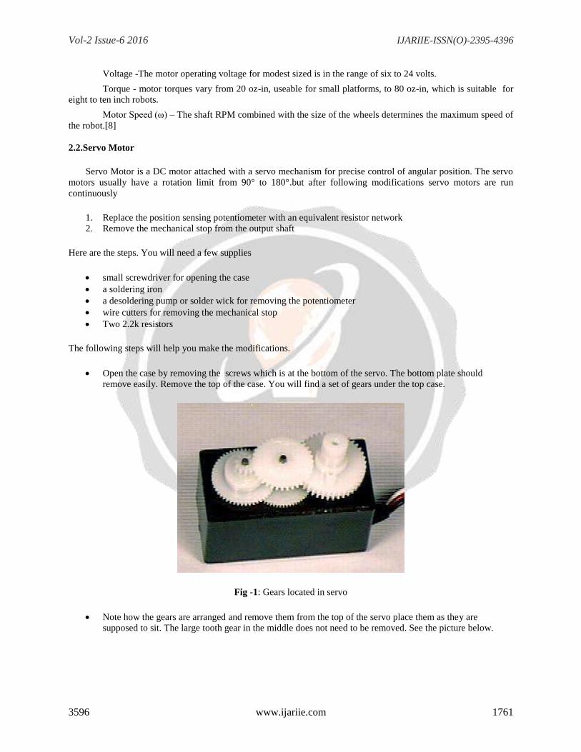
Open the case by removing the screws which is at the bottom of the servo. The bottom plate should
remove easily. Remove the top of the case. You will find a set of gears under the top case.
Fig -1: Gears located in servo
Note how the gears are arranged and remove them from the top of the servo place them as they are
supposed to sit. The large tooth gear in the middle does not need to be removed. See the picture below.

Vol-2 Issue-6 2016 IJARIIE-ISSN(O)-2395-4396
3596 www.ijariie.com 1762
Fig -2: Servo with top and gears removed
Locate and remove the two small screws on the left shaft in the picture above. These screws go through the
top case and into the drive motor.
There is a need to remove the circuit board from the case. You will probably need to press down hard on
the brass shaft on the right side. This is the top of the position potentiometer . Pressing that brass shaft
against the workbench helps push it through.
From the bottom, pry up on opposing corners of the circuit board. The board should move out with the
motor and potentiometer attached.
Fig -3: Disassembled servo motor
Now for the actual modifications. There is a need to desolder the potentiometer from the board. cut the
long leads off a quarter inch or so from the bottom. then use solder wick on the back side of the board.
Once the pot has been removed, joint resistor network in its place, place the resistors side by side and make
one pair of leads. Solder them together.The pot has been replaced by the resistor network.
Vol-2 Issue-6 2016 IJARIIE-ISSN(O)-2395-4396
3596 www.ijariie.com 1763
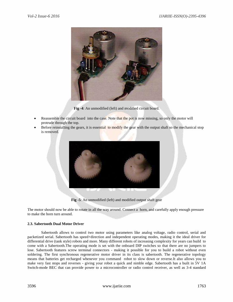
Fig -4: An unmodified (left) and modified circuit board.
Reassemble the circuit board into the case. Note that the pot is now missing, so only the motor will
protrude through the top.
Before reinstalling the gears, it is essential to modify the gear with the output shaft so the mechanical stop
is removed.
Fig -5: An unmodified (left) and modified output shaft gear
The motor should now be able to rotate in all the way around. Connect a horn, and carefully apply enough pressure
to make the horn turn around.
2.3. Sabertooth Dual Motor Driver
Sabertooth allows to control two motor using parameters like analog voltage, radio control, serial and
packetized serial. Sabertooth has speed+direction and independent operating modes, making it the ideal driver for
differential drive (tank style) robots and more. Many different robots of increasing complexity for years can build to
come with a Sabertooth.The operating mode is set with the onboard DIP switches so that there are no jumpers to
lose. Sabertooth features screw terminal connectors - making it possible for you to build a robot without even
soldering. The first synchronous regenerative motor driver in its class is sabertooth. The regenerative topology
means that batteries get recharged whenever you command robot to slow down or reverse.It also allows you to
make very fast stops and reverses - giving your robot a quick and nimble edge. Sabertooth has a built in 5V 1A
Switch-mode BEC that can provide power to a microcontroller or radio control receiver, as well as 3-4 standard
Vol-2 Issue-6 2016 IJARIIE-ISSN(O)-2395-4396
3596 www.ijariie.com 1764
analog servos. The lithium cutoff mode allows Sabertooth to operate safely with lithium ion and lithium polymer
battery packs - the highest energy density batteries available.
2.4.Radio Control
Radio control is use of radio signals to remotely control a device. Radio control is used for control
of model vehicles from a hand-held radio transmitter. Industrial, military, and scientific research organizations make
use of radio-controlled vehicles as well.Today radio control is used in industry for such devices as
overhead cranes and switchyard locomotives. Radio-controlled teleoperator is used for such purposes as inspections
and special vehicles for disarming of bombs. Some remotely controlled devices are loosely called robots only under
control of a human operator. When the receiver receives the radio signal which is sent by the transmitter , it checks it
so that it is the correct frequency and that any security codes match,
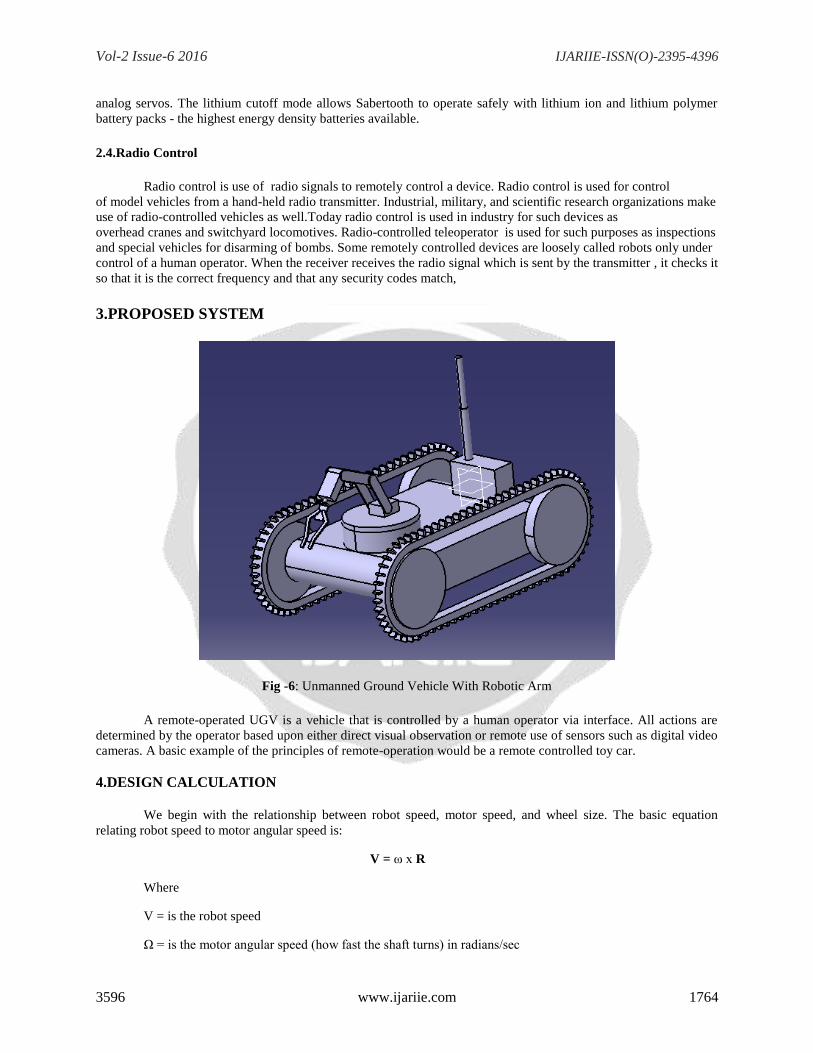
3.PROPOSED SYSTEM
Fig -6: Unmanned Ground Vehicle With Robotic Arm
A remote-operated UGV is a vehicle that is controlled by a human operator via interface. All actions are
determined by the operator based upon either direct visual observation or remote use of sensors such as digital video
cameras. A basic example of the principles of remote-operation would be a remote controlled toy car.
4.DESIGN CALCULATION We begin with the relationship between robot speed, motor speed, and wheel size. The basic equation
relating robot speed to motor angular speed is:
V = ω x R
Where
V = is the robot speed
Ω = is the motor angular speed (how fast the shaft turns) in radians/sec

Vol-2 Issue-6 2016 IJARIIE-ISSN(O)-2395-4396
3596 www.ijariie.com 1765
R = is the wheel radius
If the wheel is not directly mounted to the motor shaft, then ω is the wheel angular speed, the rotation rate
of the motor modified by any gearing interposed between the motor and the wheel . Choosing practical units, the
relationship between wheel size, motor speed, and robot speed is:
V = ω x D / 19.1
Where,
V = robot speed in inches/sec
ω = motor speed in revolutions/minute (RPM)
D = wheel diameter
19.1= is a conversion factor to make the units consistent
We can turn this equation around to calculate a required motor speed given a desired robot speed and wheel
diameter, or we can calculate a wheel diameter to provide a desired robot speed from a given motor speed. These
relationships, using the same units of rev/minute and inches, are:
ω = 19.1 x V / D
D = 19.1 x V / ω
4.1 Speed Requirement
Let’s say the average speed of a suitable competitor is Vold and we want to go faster by some factor f.
Then our average speed requirement is simply
Vavg = f x Vold
And our motor speed requirement is:
ω = 19.1 x f x Vold/D
Let’s examine picking an average speed for a contest in more detail. Average speed is just the distance traveled, X,
divided by the time taken, T.
Choose a distance appropriate to the contest. The distance between objectives, or the whole field if the rules permit.
The motor will accelerate over part of the range, S, during which the robot goes from zero to some cruising speed,
VC. For loads that are not too great, a motor will achieve a steady speed and torque over a short distance. The time
T is divided into two parts, T1, time of the acceleration over distance S, and T2, the time spend cruising at speed VC.
Then the average speed is:
Vavg = X / T = X / (T1 + T2)
Where,
X = is the total distance traveled
T1 = is the acceleration time
T2 = is the cruising time
4.2 Motor Torque

Vol-2 Issue-6 2016 IJARIIE-ISSN(O)-2395-4396
3596 www.ijariie.com 1766
C = Ff / FN
where
C = is the coefficient of friction
Ff = is the frictional force to begin motion
FN = is the normal force
Fig -7: Forces acts on body
On a level playing surface, the normal force is just the robot weight, W.
Thus the minimum required motor torque is:
T = Ff x R = C x FN x R = C x W x R
Converting units,
T = 8 x C x W x D
Where,
T = is the torque in oz-in
C = is the coefficient of friction
W = is the weight in lbs
D = is the wheel diameter in inches.
The robot acceleration is given by Newton’s second law of motion:
F = m x a
Where,
F = is the net accelerating force.
M = is the mass of the object that the force acts on
A = is the resulting acceleration.
Applying equation to the force of gravity:
W = m x g
Vol-2 Issue-6 2016 IJARIIE-ISSN(O)-2395-4396
3596 www.ijariie.com 1767
Where,
W = is an objects weight
M = is the object mass
G = is the acceleration caused by gravity
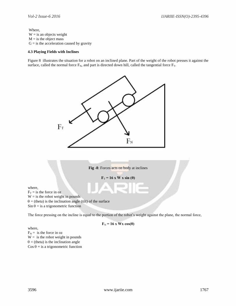
4.3 Playing Fields with Inclines
Figure 8 illustrates the situation for a robot on an inclined plane. Part of the weight of the robot presses it against the
surface, called the normal force FN, and part is directed down hill, called the tangential force FT.
Fig -8: Forces acts on body at inclines
FT = 16 x W x sin (θ)
where,
FT = is the force in oz
W = is the robot weight in pounds
= (theta) is the inclination angle (tilt) of the surface
Sin = is a trigonometric function
The force pressing on the incline is equal to the portion of the robot’s weight against the plane, the normal force,
FN = 16 x Wx cos(θ)
where,
FN = is the force in oz
W = is the robot weight in pounds
= (theta) is the inclination angle
Cos = is a trigonometric function

Vol-2 Issue-6 2016 IJARIIE-ISSN(O)-2395-4396
3596 www.ijariie.com 1768
When the gravitational tangential force pulling the robot down the incline exceeds the static friction force, FS,
sliding will occur. As the steepness of the incline increases from zero, a point will be reached when the forces are in
balance. That is when,
fS = FT
As the slope increases further, the robot will begin to slide. Since the coefficient of sliding friction is less than the
coefficient of static friction, the robot continues to slide. Using equation 11, we can calculate the coefficient of static
friction, CS, from the slope when the robot begins to slide.
CS = 16 xW x sin (θ) / 16 x W x cos(θ)
CS = tan(θ)
Where,
CS = is the coefficient of static friction
θ = is the inclination angle
Tan = is a trigonometric function
To find the torque needed to overcome the pull of gravity down the incline, we simply multiply the tangential force,
equation 22, by the wheel radius.
T = 8 x W x D x sin (θ) Where,
T = is the motor torque in oz-in
W = is the robot weight in pounds
D = is the wheel diameter in inches
= is the inclination angle.
A motor with no external load (zero torque), operating at its nominal rated voltage, will spin at its maximum rate,
the no load speed ωo.
T = Ts x (1 - ω/ωο)
Where,
ω = is the angular speed
ωo = is the no load speed
Ts = is the stall torque
T = is the torque at ω
Fig -9: PMDC Motor Characteristics
Using a multimeter we can measure the motor coil resistance. For the Globe motor it’s 13.7 ohms. Ohm’s law gives:
Vol-2 Issue-6 2016 IJARIIE-ISSN(O)-2395-4396
3596 www.ijariie.com 1769
I = V / R [8]
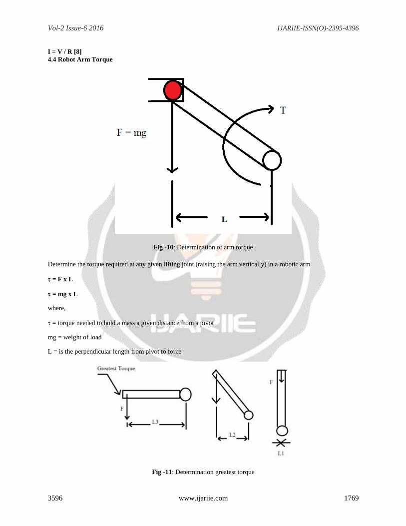
4.4 Robot Arm Torque
Fig -10: Determination of arm torque
Determine the torque required at any given lifting joint (raising the arm vertically) in a robotic arm
= F x L
= mg x L
where,
= torque needed to hold a mass a given distance from a pivot
mg = weight of load
L = is the perpendicular length from pivot to force
Fig -11: Determination greatest torque
Vol-2 Issue-6 2016 IJARIIE-ISSN(O)-2395-4396
3596 www.ijariie.com 1770
To estimate the torque required to each joint , we must choose the worst case scenario As the arm is rotated in
clockwise, L the perpendicular distance decreases from L3 to L1 (L1=0). Therefore the greatest torque is at L3 (F does
not change) & Torque is zero at L1.Motors are subjected to the highest torque when the arms is stretched out
horizontally.
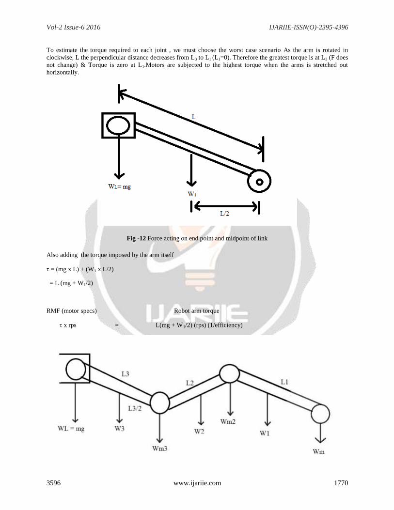
Fig -12 Force acting on end point and midpoint of link
Also adding the torque imposed by the arm itself
= (mg x L) + (W1 x L/2)
= L (mg + W1/2)
RMF (motor specs) Robot arm torque
x rps = L(mg + W1/2) (rps) (1/efficiency)

Vol-2 Issue-6 2016 IJARIIE-ISSN(O)-2395-4396
3596 www.ijariie.com 1771
Fig -13: Arm with multiple point and forces
If arm has multiple points, you must determine the torque around each joint to select the appropriate motor
3 = (mg x L3) + (W3 x L3/2)
2 = [mg x (L3+L2)] +[W3 x (L2+L3/2)] + (Wm3 x L2) + (W2 x L2/2)
1 = [mg x (L3+L2+L1)]+[W3 x (L1+L2+L3/2)]+[Wm3 x(L1+L2)] + [W2 x (L1+L2/2)] +(Wm2 x L2) (W1 x L1/2)
5. CONCLUSIONS The unmanned ground vehicles can spot the explosives or the human opposition before the soldiers can be harmed
in the combat. They can save the human soldier from the harms.With this UGVs we can reduce the coal mines
accident and occupational safety. Whenever any accident occurs, the UGV automatically detect the accident, find
the location and enter the coal mine tunnel well before the reaching of rescuers. It finds the accident location,
searches for trapped survivors to give them first aid treatment at right time and informs the rescue team about
environmental conditions and about the survivors inside the coal mine.
6. REFERENCES
[1] Ravikumar Mourya, Amit Shelke, Sourabh Satpute, Sushant Kakade, Manoj Botre,
“Design and Implementation of Pick and Place Robotic Arm”
(Issue 1, pp: (232-240), Month: April 2015 – September 2015), ISSN 2393-8471.
[2] Vansjaliya Kinjal, Prof. Tarun R. Dholariya, Dr. Charmy Patel,
”Multidimentional Motion Control of Robotic Arm”
Vol. 3, Issue 2, February 2015, ISSN (Online): 2320-9801,ISSN (Print): 2320-9798.
[3] Mr. Subhan M. A. Mr. A. S. Bhide,
” Unmanned Ground Vehicle (UGV’s) for Coal Mines”
Issue 1, Volume 2 (January 2015) ISSN: 2349-2163.
[4] Rajinder Kaur Amanpreet Kaur,,
“Unmanned Ground Vehicle”,
Volume 4, Issue 5, May 2014. ISSN: 2277 128X.
[5] Vivek Bhojak, Girish Kumar Solanki, Sonu Daultani,,
“Gesture Controlled Mobile Robotic Arm Using Accelerometer”,
Vol. 4, Issue 6, June 2015, ISSN(Online): 2319-8753 ISSN (Print): 2347-6710.
[6] S. Senthilkumar, L. Ramachandran, R. S. Aarthi,
“Pick and place of Robotic Vehicle by using an Arm based Solar tracking system”
Vol-1, Issue-7, Dec.- 2014 ISSN: 2349-6495.
[7] Anusha Ronanki , M. Kranthi ,,

Vol-2 Issue-6 2016 IJARIIE-ISSN(O)-2395-4396
3596 www.ijariie.com 1772
“Design and Fabrication of Pick and Place Robot to Be Used in Library”,
Vol. 4, Issue 6, June 2015, ISSN(Online): 2319-8753 ISSN (Print): 2347-6710.
[8] John Piccirillo, Ph.D. Huntsville, AL 35899
“The Art and Science of Selecting Robot Motors”
19 February 2009
[9] Standard Technologies of the Seattle Robotics Society
“Hacking a Servo”
[10]Dimension Engineering’s
Sabertooth dual 25A motor driver description