unstable cavitation behavior in a circular-cylindrical orifice flow abstract 1 introduction
TRANSCRIPT

CAV2001:sessionA9.003 1
Unstable Cavitation Behavior in a Circular-Cylindrical Orifice Flow
Keiichi SATO and Yasuhiro SAITO
Department of Mechanical and Mechanical Systems Engineering,
Kanazawa Institute of Technology, Nonoichi-machi, Ishikawa 921-8501, JAPAN
Abstract The cavitation characteristics were experimentally investigated about long circular-cylindrical orifices of various throat lengths including the orifice with a trip wire. Especially, the shedding process of separated vortex cavity was examined in detail with the observation using high-speed photography. The cavitation impact was measured with an accelerometer. As a result, it is found that the periodic shedding of the cloud-like cavity can be observed characteristically in the transition cavitation stage and is dependent on the formation and coalescence of micro-vortex cavities on the separated shear layer as well as the reentrant motion after the shedding and collapse. It is also pointed out that it forms a feedback loop in the self-exciting mechanism. The estimation determined from two velocity ratios is shown on the Strouhal number of cloud-like cavity. The clear shedding of cloud-like cavity appears near the cavitation impact-peak region and remains almost constant, irrespective of the difference in orifice length. The transition from the throat cavitation to the jet cavitation downstream of the orifice throat can also produce the other impact-peak stage.
1 Introduction The cavitation phenomena in a circular cylindrical orifice that makes an important role as a part of hydraulic system are also of engineering interest from viewpoints of the fluid performance, noise and erosion. In addition, it is interesting whether an axi-symmetrical flow such as a cylindrical orifice has possibility to cause the periodic cloud cavitation in a similar manner to that of separated vortex cavitation for a two-dimensional bluff body and a hydrofoil.
According to the previous research of the authors (Sato & Saito (2000)), the shedding of a cloud-like cavity in a relatively large scale was observed in a cylindrical orifice. Then, it was shown that the time-average cavity length at cavitation number with clear generation of the cloud-like cavity approximately corresponded to that of viscous separation bubble at non-cavitation state. However, the details of the unsteady shedding mechanism have not been very much clarified, though it can be indicated that there are some self-oscillations in the hydraulic system (Pilipenko & Man’ko (1998)).
In the meantime, Knapp (1955) has clarified through the pioneering work in an axisymmetric body (external flow) that the sheet cavitation with reentrant jet sheds a cloud-like cavity to the downstream direction. Selim & Hutton (1981) and Hutton (1986) pointed out that the cavitation behavior of this kind in a convergent-divergent channel could produce high impact. Kubota et al. (1987) indicated a spiral structure in the shedding cavity, and Kawanami et al. (1997) studied about the substantial role of the reentrant motion, etc. Avellan et al. (1988) also indicated the roles of the vortex sheet on the cavity interface, etc. In addition, it has been clarified by many researchers that the fixed-type cavity generates the shedding type of vortex cavity, and much knowledge has been accumulated (e.g., Shen & Peterson (1978), Le et al. (1993), de Lange et al. (1994), Pham et al. (1999), Kjeldsen et al. (2000)). Through these studies, the important roles of the reentrant jet and the vortex sheet on the cavity interface have been shown on the mechanism of occurrence of the periodical cloud-like cavity, but it seems not to be solved sufficiently.
In this report, in order to elucidate the mechanism of the shedding-type vortex cavity, experimental examination was carried out on various orifice shapes including attaching a trip wire. As a result, some points are experimentally shown about the existence of self-excited oscillation structure, and the development and shedding aspect of fixed-type cavitation from the micro-vortex cavities on the separated shear layer.

CAV2001:sessionA9.003 2
2 Experimental Apparatus and Procedure The experiment was conducted using a cavitation tunnel (Sato & Kakutani (1994)) with the circular test section of 80 mm in diameter, which had a long circular-cylindrical orifice with no inlet roundness as shown in Fig. 1. In the present study various kinds of orifices were used as shown in the table of Figure 1. The orifices A, B and C have different throat lengths each other. For Orifice-D, a trip ring was installed on the front step surface to disturb the boundary layer before the separation at the right inlet of the orifice. Orifice-E has a different throat diameter from other orifices. The motion at the cavity base, namely a re-entrant jet, can be observed along the orifice surface because of the transparent orifice wall. Pressure taps were placed near the upstream and downstream edges of the orifice throat to measure the standard pressure. One or two accelerometers of piezoelectric type (TEAC, 0.3-50kHz ±3dB) were installed on the outside wall of test section to measure the impact generated by cavitation collapse (Sato (1987)).
Observation of bubble behavior was made using a high-speed video camera system (Sato & Ogawa (1995)) as shown in Figure 2. In this system, impulsive pulses due to bubble collapse were detected with an accelerometer and conveyed to an oscilloscope. At the same time, the signal was conveyed to a high-speed video camera (KODAK EXTAPRO MODEL4540, maximum frame speed 40500fps) as a trigger, so that the bubble behaviors and the impulsive pulses could be simultaneously measured. The length of cavitating zone was measured with a still camera. The multi-exposure pictures were taken using an intermittent strobe flashing. So the time-average view of cavitating zone could be taken.
Cavitation experiments were made under constant free-stream velocity by reducing the static pressure of the tunnel. The cavitation number σ, mean velocity in the orifice throat U and Reynolds number Re are defined respectively as follows,
σ = (P2 - Pv) / (P1 - P2) (1) U = 4Q / πd2 (2) Re = U・d / ν (3)
where P1 and P2 are static pressures upstream and downstream of orifice, Pv and ν are saturated vapor pressure and kinetic viscosity of water, and Q is flow rate of water, respectively. In addition the temperature and dissolved oxygen content of water are denoted as Tw and β, respectively, and Fs is the frame speed of a high-speed video camera.
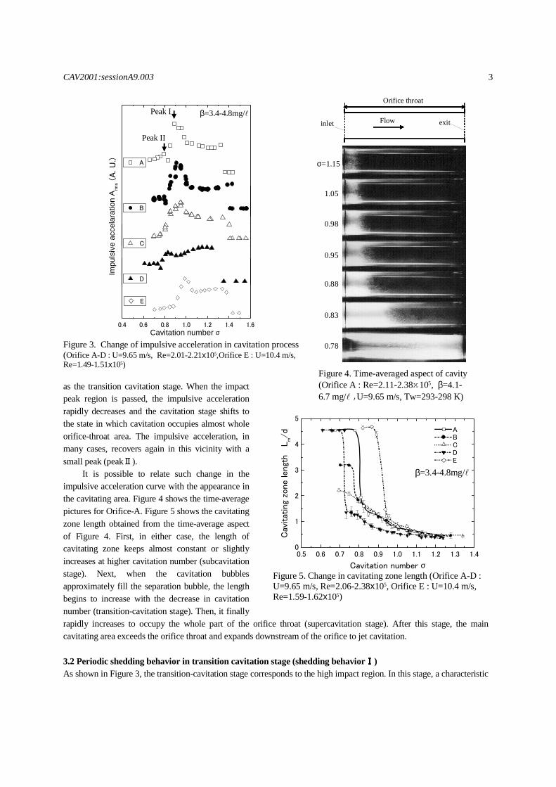
3 Experimental Results and Discussion 3.1 Cavitation developing process and impact property The relationship between cavitation number and impulsive acceleration is shown on five kinds of orifice shapes in Figure 3. In either case, the impulsive acceleration rapidly rises at a certain point with lowering cavitation number. This point is considered as the cavitation inception. With more decrease in cavitation number, the impulsive acceleration takes almost constant during some part (subcavitation stage) and, then, gradually increases to form a peak. It is possible to consider the peak region (peakⅠ)
Video Camera
Flow
Figure 2. Block diagram of measurement system
Personal Computer
Accelerometer
Digital Multi-meter
Amplifier
HS Motion Analyzer
Video Recorder
① ②to Manometer
D= φ
80
L
20d
Lucite
Accelerometer Ⅰ Accelerometer Ⅱ
Flow
Wire
φ26
diameter=φφφφ0.8
30
Figure 1. Details of test section
Orifice A B C D EL (mm) 100 70 50 100 70d (mm) 22 22 22 22 15U (m/s) 9.65 9.65 9.65 9.65 10.4Trip wire x x x O x
CAV2001:sessionA9.003 3
as the transition cavitation stage. When the impact peak region is passed, the impulsive acceleration rapidly decreases and the cavitation stage shifts to the state in which cavitation occupies almost whole orifice-throat area. The impulsive acceleration, in many cases, recovers again in this vicinity with a small peak (peakⅡ). It is possible to relate such change in the impulsive acceleration curve with the appearance in the cavitating area. Figure 4 shows the time-average pictures for Orifice-A. Figure 5 shows the cavitating zone length obtained from the time-average aspect of Figure 4. First, in either case, the length of cavitating zone keeps almost constant or slightly increases at higher cavitation number (subcavitation stage). Next, when the cavitation bubbles approximately fill the separation bubble, the length begins to increase with the decrease in cavitation number (transition-cavitation stage). Then, it finally rapidly increases to occupy the whole part of the orifice throat (supercavitation stage). After this stage, the main cavitating area exceeds the orifice throat and expands downstream of the orifice to jet cavitation. 3.2 Periodic shedding behavior in transition cavitation stage (shedding behaviorⅠⅠⅠⅠ) As shown in Figure 3, the transition-cavitation stage corresponds to the high impact region. In this stage, a characteristic
0.4 0.6 0.8 1.0 1.2 1.4 1.6
A
B
C
(A. U
.)Im
puls
ive
acce
lara
tion
A rms
Cavitation number σ
D
E
Figure 3. Change of impulsive acceleration in cavitation process (Orifice A-D : U=9.65 m/s, Re=2.01-2.21x10⁵,Orifice E : U=10.4 m/s, Re=1.49-1.51x10⁵)
Peak I
Peak II
β=3.4-4.8mg/
Figure 5. Change in cavitating zone length (Orifice A-D : U=9.65 m/s, Re=2.06-2.38x10⁵, Orifice E : U=10.4 m/s, Re=1.59-1.62x10⁵)
β=3.4-4.8mg/
0.5 0.6 0.7 0.8 0.9 1.0 1.1 1.2 1.3 1.40
1
2
3
4
5
Cav
itat
ing
zone
lengt
h
Lm/d
Cavitation number σ
A B C D E
inlet exitFlow
Orifice throat
0.78
0.83
0.88
0.95
0.98
1.05
σ=1.15
Figure 4. Time-averaged aspect of cavity (Orifice A : Re=2.11-2.38x10⁵, β=4.1-6.7 mg/ , U=9.65 m/s, Tw=293-298 K)
CAV2001:sessionA9.003 4
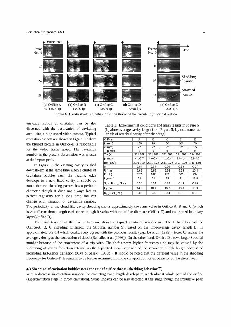
unsteady motion of cavitation can be also discerned with the observation of cavitating area using a high-speed video camera. Typical cavitation aspects are shown in Figure 6, where the blurred picture in Orifice-E is responsible for the video frame speed. The cavitation number in the present observation was chosen at the impact peak.
In Figure 6, the existing cavity is shed downstream at the same time when a cluster of cavitation bubbles near the leading edge develops to a new fixed cavity. It should be noted that the shedding pattern has a periodic character though it does not always last in perfect regularity for a long time and can change with variation of cavitation number. The periodicity of the cloud-like cavity shedding shows approximately the same value in Orifice-A, B and C (which have different throat length each other) though it varies with the orifice diameter (Orifice-E) and the tripped boundary layer (Orifice-D).
The characteristics of the five orifices are shown at typical cavitation number in Table 1. In either case of Orifice-A, B, C including Orifice-E, the Strouhal number Stm based on the time-average cavity length Lm is approximately 0.3-0.4 which qualitatively agrees with the previous results (e.g., Le et al. (1993)). Here, Uc means the average velocity at the contraction of throat (Benedict et al. (1966)). On the other hand, Orifice-D shows larger Strouhal number because of the attachment of a trip wire. The shift toward higher frequency-side may be caused by the shortening of vortex formation interval on the separated shear layer and of the separation bubble length because of promoting turbulence transition (Kiya & Sasaki (1983b)). It should be noted that the different value in the shedding frequency for Orifice-D, E remains to be further examined from the viewpoint of vortex behavior on the shear layer.
3.3 Shedding of cavitation bubbles near the exit of orifice throat (shedding behaviorⅡⅡⅡⅡ) With a decrease in cavitation number, the cavitating zone length develops to reach almost whole part of the orifice (supercavitation stage in throat cavitation). Some impacts can be also detected at this stage though the impulsive peak
FrameNo. 0
12
24
36
FrameNo. 0
8
16
24
(a) Orifice AFs=13500 fps
(b) Orifice B 13500 fps
(c) Orifice C 13500 fps
(d) Orifice D 13500 fps
(e) Orifice E 9000 fps
Orifice inlet
Figure 6 Cavity shedding behavior in the throat of the circular cylindrical orifice
Flow
Shedding cavity
Attached cavity
Orifice A B C D EL (mm) 100 70 50 100 70d (mm) 22 22 22 22 15Trip wire x x x O xTw (K) 292-298 293-296 293-296 291-296 294-296β (mg/ ) 4.1-6.7 4.6-5.4 4.1-5.4 2.9-4.4 3.9-4.8Re (x105) 2.06-2.38 2.21-2.26 2.11-2.26 2.01-2.26 1.59-1.66σ 0.94 0.94 0.95 0.83 0.97U (m/s) 9.65 9.65 9.65 9.65 10.4F (Hz) 257 242 252 365 294Lm(mm) 22 22 22 21 16.5Stm(=F x Lm / Uc) 0.36 0.34 0.36 0.49 0.29L0 (mm) 14.6 16.1 16.7 13.6 10.9StL(=Fx L0 / U) 0.39 0.40 0.44 0.51 0.31
Table 1. Experimental conditions and main results in Figure 6 (Lm:time-average cavity length from Figure 5, Lo:instantaneouslength of attached cavity after shedding)
CAV2001:sessionA9.003 5
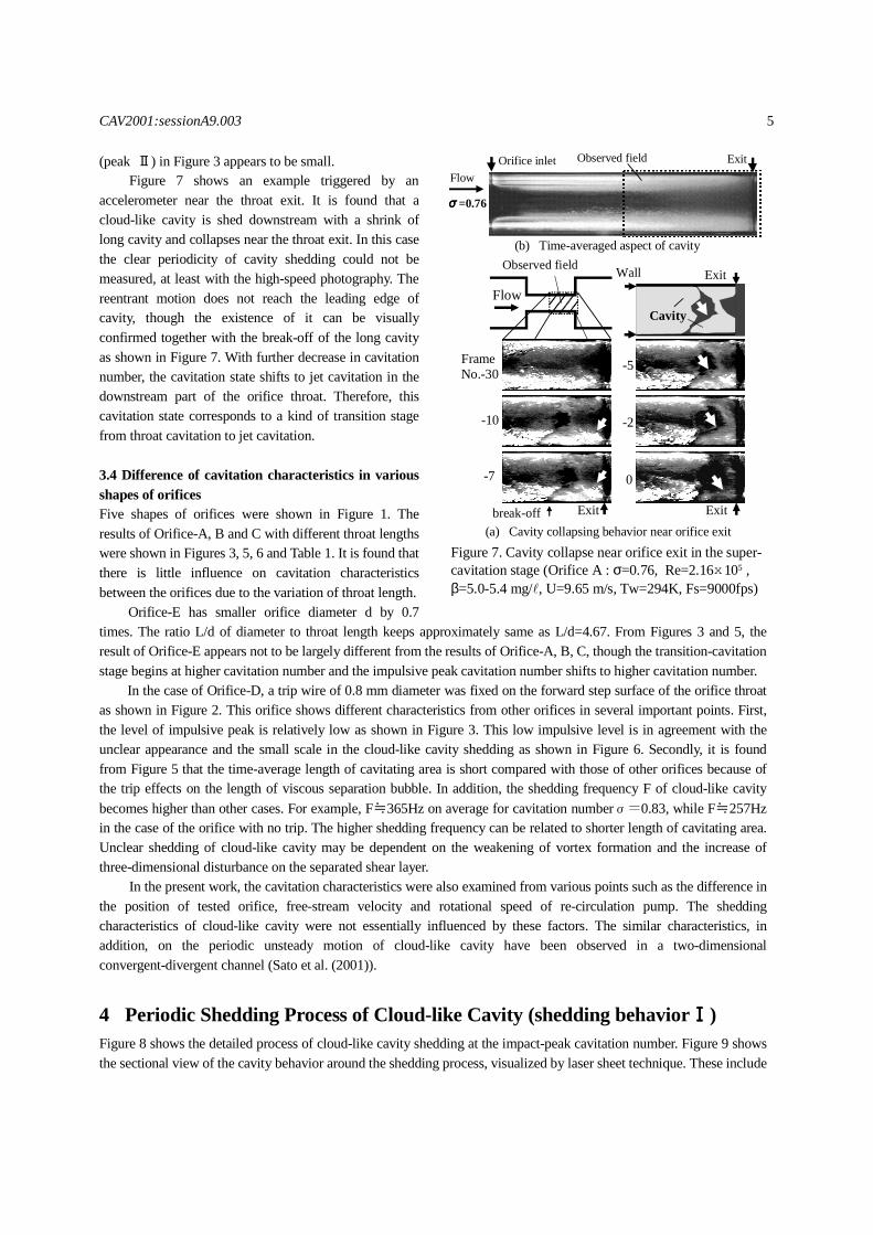
(peak Ⅱ) in Figure 3 appears to be small. Figure 7 shows an example triggered by an
accelerometer near the throat exit. It is found that a cloud-like cavity is shed downstream with a shrink of long cavity and collapses near the throat exit. In this case the clear periodicity of cavity shedding could not be measured, at least with the high-speed photography. The reentrant motion does not reach the leading edge of cavity, though the existence of it can be visually confirmed together with the break-off of the long cavity as shown in Figure 7. With further decrease in cavitation number, the cavitation state shifts to jet cavitation in the downstream part of the orifice throat. Therefore, this cavitation state corresponds to a kind of transition stage from throat cavitation to jet cavitation.
3.4 Difference of cavitation characteristics in various shapes of orifices Five shapes of orifices were shown in Figure 1. The results of Orifice-A, B and C with different throat lengths were shown in Figures 3, 5, 6 and Table 1. It is found that there is little influence on cavitation characteristics between the orifices due to the variation of throat length.
Orifice-E has smaller orifice diameter d by 0.7 times. The ratio L/d of diameter to throat length keeps approximately same as L/d=4.67. From Figures 3 and 5, the result of Orifice-E appears not to be largely different from the results of Orifice-A, B, C, though the transition-cavitation stage begins at higher cavitation number and the impulsive peak cavitation number shifts to higher cavitation number.
In the case of Orifice-D, a trip wire of 0.8 mm diameter was fixed on the forward step surface of the orifice throat as shown in Figure 2. This orifice shows different characteristics from other orifices in several important points. First, the level of impulsive peak is relatively low as shown in Figure 3. This low impulsive level is in agreement with the unclear appearance and the small scale in the cloud-like cavity shedding as shown in Figure 6. Secondly, it is found from Figure 5 that the time-average length of cavitating area is short compared with those of other orifices because of the trip effects on the length of viscous separation bubble. In addition, the shedding frequency F of cloud-like cavity becomes higher than other cases. For example, F≒365Hz on average for cavitation numberσ=0.83, while F≒257Hz in the case of the orifice with no trip. The higher shedding frequency can be related to shorter length of cavitating area. Unclear shedding of cloud-like cavity may be dependent on the weakening of vortex formation and the increase of three-dimensional disturbance on the separated shear layer.
In the present work, the cavitation characteristics were also examined from various points such as the difference in the position of tested orifice, free-stream velocity and rotational speed of re-circulation pump. The shedding characteristics of cloud-like cavity were not essentially influenced by these factors. The similar characteristics, in addition, on the periodic unsteady motion of cloud-like cavity have been observed in a two-dimensional convergent-divergent channel (Sato et al. (2001)).
4 Periodic Shedding Process of Cloud-like Cavity (shedding behaviorⅠⅠⅠⅠ) Figure 8 shows the detailed process of cloud-like cavity shedding at the impact-peak cavitation number. Figure 9 shows the sectional view of the cavity behavior around the shedding process, visualized by laser sheet technique. These include
FrameNo.-30
-10
-7
-5
-2
0
Flow
Observed field
Figure 7. Cavity collapse near orifice exit in the super-cavitation stage (Orifice A : σ=0.76, Re=2.16x10⁵ , β=5.0-5.4 mg/ , U=9.65 m/s, Tw=294K, Fs=9000fps)
(a) Cavity collapsing behavior near orifice exit
(b) Time-averaged aspect of cavity
FlowOrifice inlet Exit
σσσσ=0.76
Observed field
Exit
Cavity
Wall
Exitbreak-off Exit

CAV2001:sessionA9.003 6
the motion of the micro-vortex cavities on the separated shear layer. From these pictures, the process in the periodic shedding of the large-scale vortex cavity is observed as follows. Ⅰ: A reentrant motion starts at the end of lower part in an attached-type cavity after the shedding of a cloud-like vortex cavity (Figure 8: Frame No. 6). It causes a counter-flow to the upstream direction along the orifice wall and reaches the leading edge of the throat around Frame No.22. The motion is ascertained by the bubble behavior marching forward with vanishing the surrounding bobbles along the orifice wall. The velocity Ur of the reentrant motion is estimated to be Ur=10.8m/s on average from these pictures of Frame No. 6 to 22, which value is approximately equal to the mean velocity U=9.65m/s in the orifice throat. The mean velocity Uc based on the vena contraction can be estimated to be Uc=15.6m/s.
Figure 9. Sectional view of shedding cavities with laser sheet method (Orifice A : Re=2.21x10⁵, β=5.5 mg/ , U=9.65 m/s, Tw=295 K, Fs=9000fps)
1 3Pairing
4
FrameNo. 0 10mm21 3
8
Orifice inlet Flow
21 3
12
16
20
24
Lv
Coalescence
2 Shedding
Figure 8. Behavior of cavity shedding and re-entrant motion at impact-peak cavitaion number (Orifice A : σ=0.94, Tw=292K, Re=2.06x10⁵, β=5.6 mg/ , Fs=13500fps, U=9.65 m/s)
10mm
Lv
Lv=Separation bubble length (Sato & Saito (2000))

CAV2001:sessionA9.003 7
Ⅱ: The reentrant motion reaches the leading edge of the separation zone and then forms a new micro-vortex cavity (see, Figure 8: Frame No. 24, Figure 9: No.0, cavity ①). The cavitating part inside the attached cavity partially disappears, especially in the lower portion of the cavity, because of the reentrant motion. On the other hand, there are several micro-vortex cavities on the separated shear layer (e.g. cavities ② and ③). Ⅲ: These vortex cavities on the separated shear layer move downstream. The cavity ① grows to a new attached cavity. The cavity ②, on the other hand, moves rapidly and coalesces with cavity ③ growing without translation of itself, probably near the end of separation bubble. The cavities ②, ③ glows and rolls up largely with the pairing motion. Ⅳ: The new attached cavity grows to a sufficient scale (cavity ①). The cavity ② moves downstream in the coalescence with the existing cavity ③ and is shed downstream from the region of attached cavity as a cloud-like cavity of large scale. It should be noted that both the growing velocity Uv of attached cavity ① and the shedding velocity Us of cavity ② (in this case, about 10m/s) are approximately constant during this process as shown in Figure 8. The shedding and collapse of the cloud-like cavity (②, ③) is conveyed to the upstream part as the feedback information through the reentrant motion. The convection velocity Uv of the vortex cavity ① forming the attached cavity is estimated to be about 5.4m/s from the high-speed pictures. When the length of the new cavity is denoted as Lo, the time period Tc from the start of reentrant motion to the shedding of vortex cavity is given by the following equation.
Tc = Lo/Ur + Lo/Uv (4)
Therefore, the Strouhal number based on the cavity length Lo and the average throat velocity U is given, only from two velocity ratios as follows. The values of these velocity ratios are crucial in the present problem.
StL = F×Lo/U = 1/(U/Ur + U/Uv) (5)
As a result, in the case of Figure 8, StL=0.37. The value also becomes StL=0.23 using Uc in consideration of the contraction coefficient (Benedict et al. (1966)). These values are compared to that in Table 1.
On the other hand, we try to estimate the Strouhal number from an assumption based on the result of Figures 8 and 9, though the velocity ratios may depends on various flow conditions. It is assumed that (1) the reentrant velocity Ur is approximately equal to the mean throat velocity U and (2) the cavity formation velocity Uv is about 0.5×U if it is considered as the convection velocity of large-scale vortices in the separation bubble (Kiya & Sasaki (1983a)). Following these assumptions, the Strouhal number is approximately estimated to be StL = 1/3, where it should be noted that the present ratio of Ur/Uv = 2 agrees with the ratio of “growing time of leading-edge cavity” to ”period of reentrant jet” given by Le et al. (1993). As stated above, the periodic process of the formation, coalescence, growth, shedding and collapse is continued under the role of the reentrant motion as the feedback mechanism. The close relation of this process can be pointed out with the micro-vortices on the separated shear layer and the viscous separation bubble. About this kind of vortex behavior and periodic unsteady phenomena, it may be useful to relate with the self-sustaining oscillation phenomena in the free separated shear layer or free-jet (e.g., Rockwell & Naudasher (1978), Ho & Huerre (1984)).
5 Concluding Remarks Periodic unsteady motion of separated vortex cavitation was experimentally investigated in a cylindrical orifice flow. The shedding process of cloud-like cavity, especially, was made clear with detailed pictures taken by a high-speed video camera. The results were examined from several viewpoints such as the throat length of orifice, the diameter of orifice and boundary layer trip. The main results are summarized as follows.
1. The periodic shedding of relatively large-scale vortex cavity (in this work, denoted by cloud-like cavity) can be measured characteristically in the transition-cavitation stage from the subcavitation state to the supercavitation state. In this stage, relatively high cavitation impact is caused with the shedding and collapse behavior of the cavity.
2. The periodic shedding process of cloud-like cavity is dependent on the formation and coalescence of

CAV2001:sessionA9.003 8
micro-vortex cavities on the separated shear layer and the reentrant motion after the shedding. It can be considered as a self-excited periodic phenomenon with the reentrant motion as the feedback mechanism.
3. The periodic behavior can be altered by the change in the characteristics of separated shear layer using a trip wire, etc. In the case of the present work, the shedding of cavity was weakened in regularity and shifted to a higher range in frequency. The cavitation impact itself became weaker.
4. The region from the throat cavitation to the jet cavitation downstream of the orifice throat can be pointed out as the second impulsive-peak stage. In this region a cluster of bubbles shed from long developed cavity causes the cavitation impact around the exit part of the orifice throat.
The cavitation tunnel has various sources of disturbance and sometimes the mechanism of amplification. The relation of the present result with these factors remains unsolved completely. It is, as a matter of course, pointed out that in the stage of transition-cavitation the separated vortex cavitation can cause the characteristic motion with the periodic shedding and the severe collapse of cloud-like cavity as well as the reentrant motion. It is very important problem since it can be closely related to the cavitation vibration, noise and erosion.
Acknowledgment This work is supported by the Grant-in-Aid for the Scientific Research of the Ministry of Education, Science and Culture of Japan.
References Avellan, F., Dupont, P. and Ryhming, I., (1988), Proc. 17th ONR Symp. on Naval Hydrodynamics, 317-329. Benedict, R.P., Carlucci, N.A. and Swetz, S.D., (1966), Trans. ASME, J. Engineering for Power, 88, 73-81. de Lange, D. F., de Bruin, G. J. and van Wijngaarden, L., (1994), Proc. the Second Int. Symp. on Cavitation, Tokyo,
45-49. Ho, C.M. and Huerre, P., (1984), Ann. Rev. Fluid Mech., 16, 365-424. Hutton, S. P., (1986), Proc. Int. Symp. on Cavitation, Sendai, 21-29. Kawanami, Y., Kato, H., Yamaguchi, H., Tanimura, M. and Tagaya, Y., (1997), Trans. ASME, J. Fluids Eng., 119,
788-794. Kiya, M. and Sasaki, K., (1983a), J. Fluid Mech., 137, 83-113. Kiya, M. and Sasaki, K., (1983b), J. Wind Eng. & Industrial Aerodynamics, 14, 375-386. Kjeldsen, M., Arndt, R.E.A. and Effertz, M., (2000), Trans. ASME, J. Fluids Eng., 122, 481-487. Knapp, R.T., (1955), Trans. ASME, 77, 1045-1054. Kubota, S., Kato, H., Yamaguchi, H. and Maeda, M., (1987), Proc. Int. Symp. on Cavitation Research Facilities &
Techniques, ASME, FED-57, 161-168. Le, Q., Franc, J.P. and Michel, J.M., (1993), Trans. ASME, J. Fluids Eng., 115, 243-248. Pham, T.M., Larrarte, F. and Fruman, D.H., (1999), Trans. ASME, J. Fluids Eng., 121, 289-296. Pilipenko, V.V. and Man’ko, I.K., (1998), Proc. Third Int. Conf. on Pumps and Funs, Beijing. Rockwell, D. and Naudascher, E., (1978), Trans. ASME, J. Fluids Eng., 100, 152-165. Sato, K., (1978), Proc. Int. Symp. on Cavitation Research Facilities & Techniques, ASME, FED-57, 115-122. Sato, K. and Kakutani, K., (1994), JSME Int. Journal, Ser. B, 37-2, 306-312. Sato, K. and Ogawa, N., (1995), Cavitation and Gas-Liquid Flow in Fluid Machinery Devices, ASME, FED-226,
119-125. Sato, K., Saito, Y. and Ohta, H., (2000), ASME FEDSM2000, 11023, 1-7. Sato, K., Nakamura, H. and Saito, Y., (2001), Proc. The 3rd ISMTMF, Fukui, to be presented. Selim, S. M. A. and Hutton, S. P., (1981), Cavitation Erosion in Fluid Systems, ASME, 15-25. Shen, Y.T. and Peterson, F.B., (1978), Proc. 12th ONR Symp. on Naval Hydrodynamics, 362-384.