up to 1 - movetec · amplifier unit gv-21/21p gv-22/22p ... perform the datum tuning. wire-saving...
TRANSCRIPT
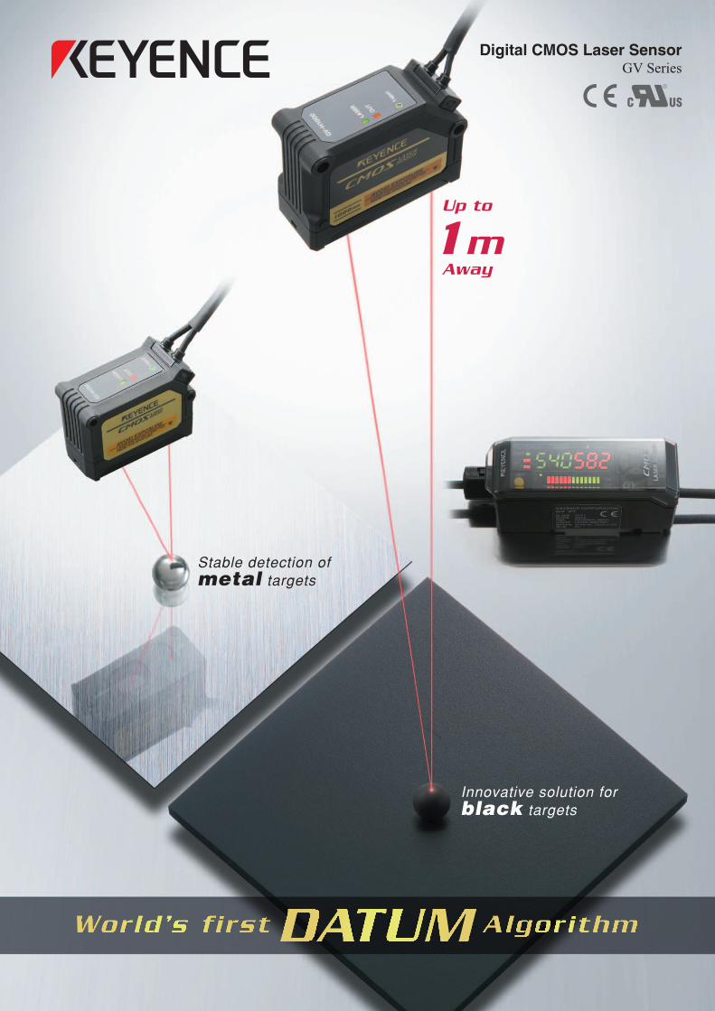
Digital CMOS Laser SensorGV Series
Stable detection of metal targets
Innovative solution for black targets
Up to
1m Away
2
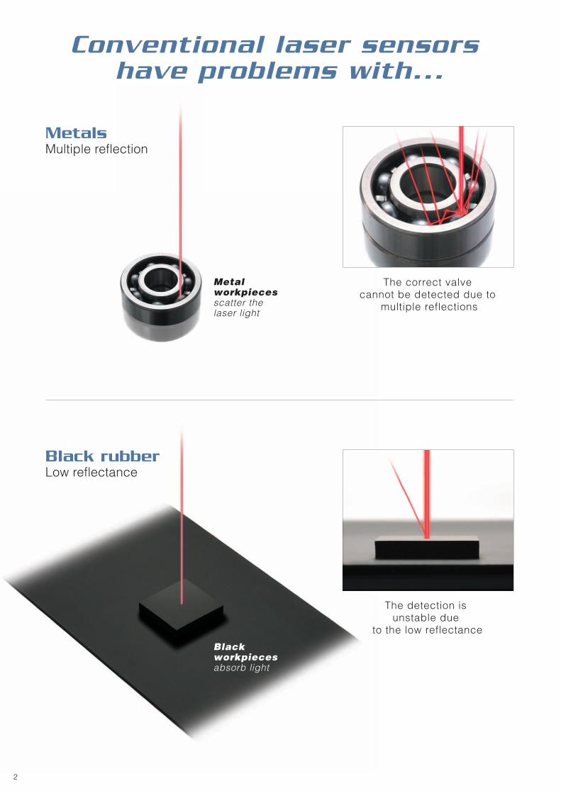
MetalsMultiple reflection
Black rubberLow reflectance
Conventional laser sensors have problems with...
Metal workpieces scatter the laser light
Black workpieces absorb light
The correct valve cannot be detected due to
multiple reflections
The detection is unstable due
to the low reflectance
3
G V S e r i e s
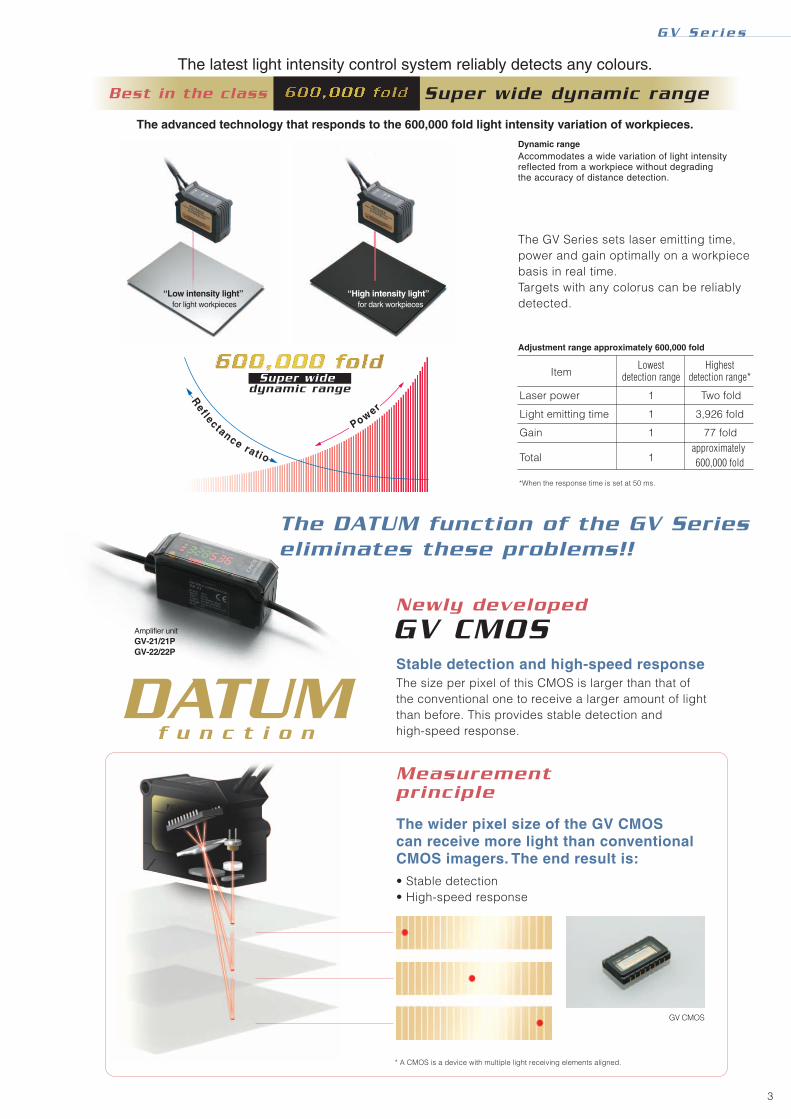
The DATUM function of the GV Series eliminates these problems!!
Newly developed
GV CMOS
Measurement principle
The wider pixel size of the GV CMOS can receive more light than conventional CMOS imagers. The end result is:• Stable detection• High-speed response
Stable detection and high-speed response
Amplifier unitGV-21/21PGV-22/22P
f u n c t i o nDATUM
GV CMOS
* A CMOS is a device with multiple light receiving elements aligned.
*When the response time is set at 50 ms.
ItemLowest
detection rangeHighest
detection range*
Laser power
Light emitting time
Gain
Total
Two fold
77 foldapproximately 600,000 fold
3,926 fold
1
1
1
1
Adjustment range approximately 600,000 fold
Dynamic range
The latest light intensity control system reliably detects any colours.
Super wide dynamic rangeBest in the class
The advanced technology that responds to the 600,000 fold light intensity variation of workpieces.
Reflectance ratio
Power
Super wide dynamic range
“Low intensity light” for light workpieces
“High intensity light” for dark workpieces
Accommodates a wide variation of light intensity reflected from a workpiece without degrading the accuracy of distance detection.
The GV Series sets laser emitting time, power and gain optimally on a workpiece basis in real time. Targets with any colorus can be reliablydetected.
The size per pixel of this CMOS is larger than that of the conventional one to receive a larger amount of light than before. This provides stable detection and high-speed response.
4
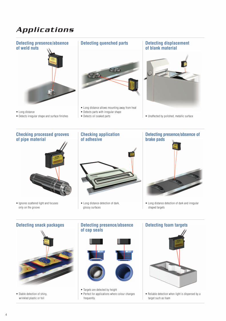
Applications
• Ignores scattered light and focuses only on the groove
• Long distance detection of dark, glossy surfaces
• Long distance detection of dark and irregular shaped targets
• Unaffected by polished, metallic surface• Long distance• Detects irregular shape and surface finishes
• Long distance allows mounting away from heat• Detects parts with irregular shape• Detects oil soaked parts
• Reliable detection when light is dispersed by a target such as foam
• Targets are detected by height• Perfect for applications where colour changes frequently.
• Stable detection of shiny, wrinkled plastic or foil
Detecting presence/absence of weld nuts
Detecting quenched parts Detecting displacement of blank material
Checking processed grooves of pipe material
Checking application of adhesive
Detecting presence/absence of brake pads
Detecting snack packages Detecting presence/absence of cap seals
Detecting foam targets

5
Detection is understood at one view.
Sensor Head
Four variations ranging from long-distance to high-accuracy detection.
Amplifier unit
The power is supplied through the side connector when connecting expansion units. This saves two wires per unit (power +, -).
When expansion units are connected, up to two adjacent units can operate in close proximity to each other with no interference.
This bar LED shows you the detection state at a glance.
This indicator tells you from the reflection whether the target is at the optimal position for detection. Make sure that the 1 spot indicator is lit when you perform the DATUM tuning.
Wire-saving structure! Up to four units can be connected
Interference suppression function
Bar LED
1 spot indicator
•The GV Series’ amplifiers should not be connected with those of other models.
• Those two units should be set for the same response time..
• This Interference suppression function is invalid for response times of 20 or 50 ms.
Short-range typeGV-H45
Middle-range typeGV-H130
Long-range typeGV-H450
Ultra Long-range typeGV-H1000[Coming Soon]
45 mm
130 mm
450 mm
1000 mm
CloseOutput ON
Near the setting value
Output ON
DistantOutput OFF
External input (selectable)External shift input--------Bank switching input-----Timing input----------------
The current value can be shifted to any value. The bank switches two setting values with each other. This input enables the output.
Timer function (selectable)Off-delay, On-delay, One-shotOn-delay/Off-delay, On-delay/One-shot
There is a multiple reflection
No multiple reflection
Head side
Amplifier side
Head side
Amplifier side
G V S e r i e s
Washable sensor head (head only) <IP67>Rugged, IP67-rated sensor heads can be put to the test in harsh environments.

6
World’s first DATUM Algorithm <Patent pending>
When the DATUM (background, reference surface) tuning is performed, workpieces can be correctly detected.
When performing the DATUM tun-ing (reference surface calibration) with a target on a conveyor (back-ground), the values are set slightly above and slightly below the con-veyor position. With no workpiece in place, the light waveform falls within this range.
Detection image CMOS light received image
“Output OFF”
Setting range
CMOS
Light waveform
CONVEYOR
<<< DATUM tuning >>>Easy tuning just by pressing the [SET] button with a target on a conveyor
The CMOS light receiving position changes
The distance changes
The workpiece is judged as present
“Output ON”
2 peaks appear on the waveform
The light receiving pattern changes
The workpiece is judged as present
“Output ON”
The light is not reflected properly
The distance changes
The workpiece is judged as present
“Output ON”
CMOS light received image
CMOS
Setting range
CMOS light received image
CMOS
Setting rangeLight waveform
CMOS light received image
CMOS
Setting rangeLight waveform
Detection image
CONVEYOR
Detection image
CONVEYOR
Detection image
CONVEYOR
<<< Detection example 1 >>>Flat workpiece
<<< Detection example 2 >>>Rough workpiece
<<< Detection example 3 >>>Round workpiece
DATUM ALGORITHM Based on:• Distance• Received light pattern

7
Translucent plastic container
Detecting cap height
Other convenient sensing algorithms
Some workpieces reflect the light from both top and bottom surfaces, making detection difficult. The surface detection mode ignores all other reflections and detects only the nearest surface.
Even when the target comes too close to the sensor head and does not enter the detecting area, this function keeps the previous ON/OFF state.
<<< Surface detection mode >>>With a workpiece that has a dual reflection
<<< Clamp function >>>When the target comes too close to the sensor head
Judgment Cancellation
A B
CMOS
Keep
Setting value
ABC
CMOS
OFFONON
A
ACover surface
Cover inside
Translucent cover thickness
B
B
A
B
C
Setting value
Controlling tension of a rubber sheet
The display is kept until OFF
Undetectable
OFF at the falling edge Only the target is detectedON at the rising edge
Setting value
Conveyor
Setting value
Position display
Output
Output
Setting value
Change amount
(a) Distance detection mode
(b) Edge hold mode
(a) Distance detection mode
(b) Edge hold mode
“Does not turn ON”“ON”“ON” “ON”
“ON”“ON”“ON”
<<< Edge hold mode >>><Patent pending>With an unstable background
Normal state With an unstable background
This operation mode ignores slow distance changes and detects only sudden changes in height (workpieces). The GV Series detects the change of the distance so the detection is not affected by the traveling speed of the workpieces.
Edge Hold Detection of a workpiece
on a conveyor
G V S e r i e s
8
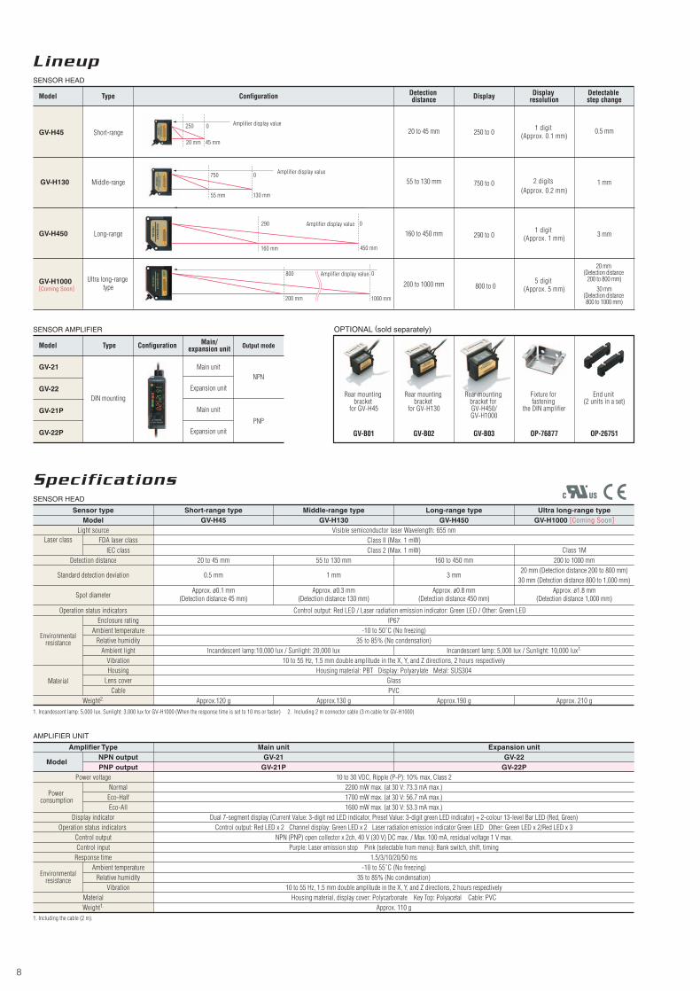
Lineup
Specifications
Sensor type Short-range type Middle-range type Long-range typeGV-H45 GV-H130
Visible semiconductor laser Wavelength: 655 nmClass II (Max. 1 mW)Class 2 (Max. 1 mW)
55 to 130 mm
1 mm
Enclosure ratingAmbient temperature
Relative humidityAmbient light
VibrationHousing
Lens coverCable
Ambient temperatureRelative humidity
Vibration
NormalPower
consumption
Model
Eco-Half
NPN outputPNP output
Eco-All
160 to 450 mm
3 mm
20 to 45 mm
0.5 mm
GV-H450Ultra long-range type
GV-H1000 [Coming Soon]
Approx.120 g Approx.130 g Approx.190 g
200 to 1000 mmClass 1M
20 mm (Detection distance 200 to 800 mm)30 mm (Detection distance 800 to 1,000 mm)
Approx. 210 g
Detection distance
Standard detection deviation
Spot diameter
Material
Weight2.
MaterialWeight1.
Operation status indicators
Display indicator
Amplifier Type Main unit Expansion unitGV-21 GV-22
GV-21P GV-22P10 to 30 VDC, Ripple (P-P): 10% max, Class 2
2200 mW max. (at 30 V: 73.3 mA max.)1700 mW max. (at 30 V: 56.7 mA max.)1600 mW max. (at 30 V: 53.3 mA max.)
Dual 7-segment display (Current Value: 3-digit red LED indicator, Preset Value: 3-digit green LED indicator) + 2-colour 13-level Bar LED (Red, Green)Control output: Red LED x 2 Channel display: Green LED x 2 Laser radiation emission indicator Green LED Other: Green LED x 2/Red LED x 3
NPN (PNP) open collector x 2ch, 40 V (30 V) DC max. / Max. 100 mA, residual voltage 1 V max.Purple: Laser emission stop Pink (selectable from menu): Bank switch, shift, timing
1.5/3/10/20/50 ms-10 to 55˚C (No freezing)
35 to 85% (No condensation)10 to 55 Hz, 1.5 mm double amplitude in the X, Y, and Z directions, 2 hours respectively
Housing material, display cover: Polycarbonate Key Top: Polyacetal Cable: PVCApprox. 110 g
Power voltage
Operation status indicatorsControl outputControl input
Response time
Approx. ø0.1 mm(Detection distance 45 mm)
Approx. ø0.3 mm(Detection distance 130 mm)
Approx. ø0.8 mm(Detection distance 450 mm)
Approx. ø1.8 mm(Detection distance 1,000 mm)
Control output: Red LED / Laser radiation emission indicator: Green LED / Other: Green LEDIP67
-10 to 50˚C (No freezing)35 to 85% (No condensation)
10 to 55 Hz, 1.5 mm double amplitude in the X, Y, and Z directions, 2 hours respectivelyHousing material: PBT Display: Polyarylate Metal: SUS304
GlassPVC
Incandescent lamp:10,000 lux / Sunlight: 20,000 lux Incandescent lamp: 5,000 lux / Sunlight: 10,000 lux1.
FDA laser classLaser classIEC class
ModelLight source
SENSOR HEAD
SENSOR HEAD
SENSOR AMPLIFIER OPTIONAL (sold separately)
AMPLIFIER UNIT
Model
GV-22
GV-21P
GV-22P
Configuration Main/expansion unitType Output mode
GV-21
DIN mounting
NPN
PNP
Main unit
Expansion unit
Main unit
Expansion unit
Model
GV-H451 digit
(Approx. 0.1 mm)
2 digits (Approx. 0.2 mm)
1 digit (Approx. 1 mm)
Type Configuration Display resolutionDisplayDetection
distanceDetectable step change
3 mm
1 mm
0.5 mmShort-range
Middle-range
Long-range
5 digit (Approx. 5 mm)
20 mm (Detection distance
200 to 800 mm)30 mm
(Detection distance 800 to 1000 mm)
GV-H450
Ultra long-range type
GV-H1000[Coming Soon]
GV-H130
Environmentalresistance
1. Incandescent lamp: 5,000 lux, Sunlight: 3,000 lux for GV-H1000 (When the response time is set to 10 ms or faster)
1. Including the cable (2 m).
2. Including 2 m connector cable (3 m cable for GV-H1000)
Environmentalresistance
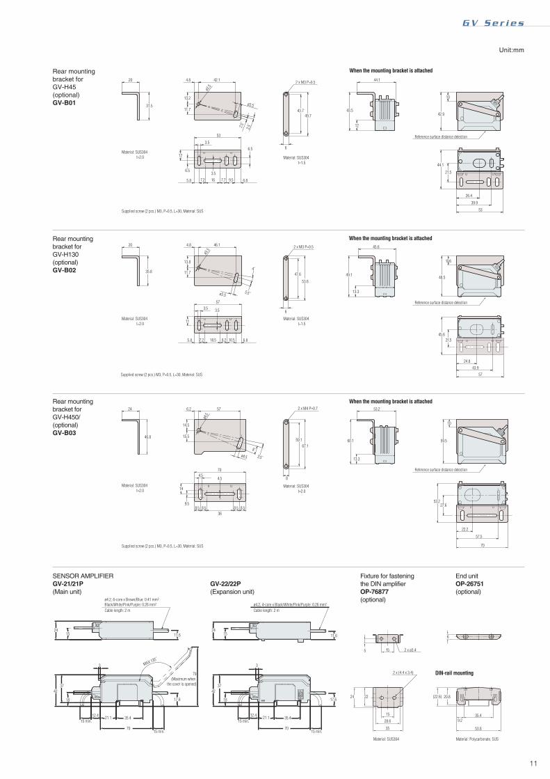
Rear mounting bracket
for GV-H45
GV-B01
Rear mounting bracket
for GV-H130
GV-B02
Rear mounting bracket for GV-H450/GV-H1000
GV-B03
Fixture for fastening
the DIN amplifier
OP-76877
End unit (2 units in a set)
OP-26751
20 mm 45 mm
750 0
290 0
160 mm 450 mm
55 mm 130 mm
250 Amplifier display value
Amplifier display value
800 0
200 mm 1000 mm
Amplifier display value
Amplifier display value
0
800 to 0200 to 1000 mm
160 to 450 mm
55 to 130 mm
20 to 45 mm
290 to 0
750 to 0
250 to 0

9
Dimensions Unit:mm
G V S e r i e s
SENSOR HEAD
GV-H1000[Coming Soon]
Indicator
2 x ø3.2 (mounting hole)
2 x ø2.5, 2-core shielded, Cable length 3 mCentre of emitted light
Centre of received light
Reference surface for distance detection
ø4.5
8˚3.5˚
ø4.5
Mounting bracket (accessory)
Material: SUS304 t=2.0
Material: SUS304 t=2.0
Material: SUS304 t=2.0
Material: SUS304 t=2.0
Material: PET t=0.2.
Supplied screw (2 pcs.) M3, P=0.5, L=30, Material: SUS
2 x M4 P=0.7
2 x M4 P=0.7
When the mounting bracket is attached
Insulation sheet (accessory) When the insulation sheet is attached
Centre of emitted light
Reference surface for distance detection
When the mounting bracket is attached
3.5˚
8˚
Rear mounting bracket for GV-H1000 (optional)GV-B03
Supplied screw (2 pcs.) M3, P=0.5, L=30, Material: SUS
Reference surface distance detection
I /O Circuit Diagram
Output circuit Input circuit
*1 Pink: Bank switching input/Shift input/Timing input, Purple: Emission stop input*2 The power line (blue) of the main unit and that of the expansion unit are common inside through the connector.
*1 Pink: Bank switching input/Shift input/Timing input, Purple: Emission stop input*2 The power line (brown) of the main unit and that of the expansion unit are common inside through the connector.
*1 The power lines (brown and blue) of the main unit and those of the expansion unit are common inside through the connector.*2 Black: Control output 1/White: Control output 2
*1 The power lines (brown and blue) of the expansion unit are common inside through the connector.*2 Black: Control output 1/White: Control output 2
Emission stop input, Bank switching input, Shift input, Timing input
GV-21/22GV-21
GV-21P/22P
(Short-circuit current 1 mA max.)
(Short-circuit current 2 mA max.)
Pink/Purple
5 VDC
0 V
PLC etc.
PLC etc.
Sens
or m
ain ci
rcui
tSe
nsor
main
circ
uit
GV-21P
5 to 40 VDC
10 to 30 VDCBrown*1 Brown*1
Brown*2
*1
Pink/Purple*1
Blue*1Blue*1
Blue*2
Black/White*2
Black/White*2
Over
curre
nt
prot
ectio
n cir
cuit
Over
curre
nt
prot
ectio
n cir
cuit
0 V
10 to 30 VDC
Load
0 V
Sens
or m
ain ci
rcui
t
Sens
or m
ain ci
rcui
t
10 to 30 VDC
Load
GV-22 GV-22P
5 to 40 VDCBlack/White*2
Over
curre
nt
prot
ectio
n cir
cuit
Over
curre
nt
prot
ectio
n cir
cuit
Load
Sens
or m
ain ci
rcui
t
Sens
or m
ain ci
rcui
t
Load
27.2
55.820.8
0.6 45 4.5
4.5
5766
50.1
7.5
12
4.5
42
76
22
24 6.2
14.5
15.5
70
36
57
46.8
5759.1
59.1 60.1 59.5
53.227.6
22.257.5
70
10
13.3
67.1
67.1
53.2
53.8
8.3
76
21.8
636.9
7.0
7.0
6.0
80
11.5
52.5 2 x ø4.5
57
15.5
25.6 51.2
55.3
17.1
18.5
8
8
69.8
32.415.5
4.5
9.1 3.8
9.1 18.5 5.3
15.5
16.4
3.6
12
13.6
13.6
ø4.5
ø4.5
4.5
14
9.58.5 8.5 8.5 8.5
4.5
0 V
10 to 30 VDC
0 V

10
Dimensions
SENSOR HEAD
GV-H45
SENSOR HEAD
GV-H130
SENSOR HEAD
GV-H450
3.5
2.5˚2.5˚
2 x M3 P=0.5
2 x ø3.5 4.9
5
5
4
Insulation sheet (accessory) When the insulation sheet is attached
Insulation sheet (accessory) When the insulation sheet is attached
2 x M3 P=0.5
5.5˚4˚
Indicator
Indicator
Indicator
2 x ø3.2 (mounting hole)
2 x ø3.2 (mounting hole)
2 x ø3.2 (mounting hole)
2 x ø2.5, 2-core shielded, Cable length 2 m
2 x ø2.5, 2-core shielded, Cable length 2 m
Centre of emitted light
Centre of received light
Centre of emitted light
Centre of received light
Centre of emitted lightCentre of received light
Reference surface for distance detection
Reference surface for distance detection
2 x ø2.5, 2-core shielded, Cable length 2 mReference surface for distance detection
ø4.5
8˚3.5˚
ø4.5
Mounting bracket (accessory)
Material: SUS304 t=2.0
Material: SUS304 t=2.0
Material: SUS304 t=2.0
Material: SUS304 t=2.0
Material: PET t=0.2.
Material: PET t=0.2.
Material: PET t=0.2.
Supplied screw (2 pcs.) M3, P=0.5, L=30Material: SUS
Material: SUS304 t=2.0
Supplied screw (2 pcs.) M3, P=0.5, L=30Material: SUS
Material: SUS304 t=2.0
Supplied screw (2 pcs.) M3, P=0.5, L=30Material: SUS
2 x M4 P=0.7
When the mounting bracket is attached
Mounting bracket (accessory) When the mounting bracket is attached
Mounting bracket (accessory) When the mounting bracket is attached
Insulation sheet (accessory) When the insulation sheet is attached
Centre of emitted light
Reference surface for distance detection
Centre of emitted light
Reference surface for distance detection
Centre of emitted light
Reference surface for distance detection
27.2
55.820.8
0.6 45 4.5
4.5
5766
50.1
7.5
12
4.5
42
76
22
5759.1
67.1 53.8
8.3
76
21.8
636.9
7
7
6
80
11.5
52.5 2 x ø4.5
57
15.5
25.6 51.2
55.3
17.1
18.5
8
69.8
32.415.5
4.5
9.1 3.8
9.1 18.5 5.3
15.5
16.4
3.6
12
13.6
13.6
22.6 0.6 29.7 3.2
3.2
43.7
42.4
58.5 42.1
11.7
33.7
16.2
21.5
9.9
12
44.1
60
42
20.1
35.2
8.2
49.7
6
6
24.1
11.6
15.4
34.7 3.23.2
46.1
11.7
52.5
38.5
4.8
3.53.5
46.157.2
ø3.5
ø3.5
31.322.1
47.653.6
46.94.4
5
5
17.5
45.6
62
44.6
22.5
7.9
37.2
13.3
18.1
4
62.5 46.1
11.7
2 x ø3.539.7
8.2
11.7
12
6.54.86.7 15
41
3.611.6
62
20
10.5
42.3
23.2
42.148.5
33.536
11.7
38.3
9.5
60
4.8 6.613.86.5
12
4.8
3.5
3.530
18.3
42.155.2
ø3.511.7
20
9.1
9.1
3.6
13.7
38.3
4˚
11
G V S e r i e s
3 3
2 x M3 P=0.5
Rear mounting bracket for GV-H45 (optional)GV-B01
Rear mounting bracket for GV-H130 (optional)GV-B02
When the mounting bracket is attached
2.5˚
2.5˚
Supplied screw (2 pcs.) M3, P=0.5, L=30, Material: SUS
Reference surface distance detection
2 x M3 P=0.5
5.5˚
4˚
Supplied screw (2 pcs.) M3, P=0.5, L=30, Material: SUS
When the mounting bracket is attached
Reference surface distance detection
24 22
35
28.6
15
2 x (4.4 x 3.4)
5
6
15 2 x ø3.4
35.4
53.8
15 1524 24
11.6 11.6
17.6 17.618 18
37 3742 42
GV-22/22P(Expansion unit)
SENSOR AMPLIFIERGV-21/21P(Main unit)
Fixture for fastening the DIN amplifierOP-76877(optional)
End unitOP-26751(optional)
Material: SUS304 t=2.0
Material: SUS304 t=2.0
Material: SUS304 t=1.5
Material: SUS304 t=2.0
Material: SUS304 t=1.5
Material: SUS304 t=2.0
2 x M4 P=0.7
When the mounting bracket is attached
DIN-rail mounting
3.5˚
8˚
Rear mounting bracket for GV-H450/(optional)GV-B03
Supplied screw (2 pcs.) M3, P=0.5, L=30, Material: SUS
Cable length: 2 m
15 min. 15 min.12.4 12.4 21.1 21.135.4 35.4
15 min. 15 min.
MAX 135˚
ø4.2, 6-core x Brown/Blue: 0.41 mm2
Black/White/Pink/Purple: 0.26 mm2
79(Maximum when
the cover is opened)
Cable length: 2 m
Material: SUS304 Material: Polycarbonate, SUS
ø4.2, 4-core x Black/White/Pink/Purple: 0.26 mm2
Reference surface distance detection
24
12
11
13.8
11.7
53
6.8
6.8
47.6
45.6
48.5
45.6
24.8
43.9
57
21.5
10.6
49.1
13.3
53.6
6
43.749.7
66.5
20
35.8
4.8 46.1
57
3.5
3.5
3.53.5
13.2
11.7
6.5
5.8
5.8
31.5
20 4.8
ø3.5
ø3.5
42.1 44.1
43.5
10
21.5
42.9
44.1
26.4
39.9
53
12
6.2
14.5
15.5
70
36
57
46.859.1 60.1 59.5
53.227.6
22.2
57.5
70
10
13.3
67.1
53.2
8
ø4.5
ø4.5
4.5
14
9.58.5 8.5 8.5 8.5
4.5
70 70
(22.6)
9.2
20.8
ø3.5
ø3.5
7.2 16 7.7 9.5
7.2 18.5 8.2 10.5
Unit:mm
© KEYENCE CORPORATION, 2007 GV-WW-C-E 0057-2 000841 Printed in Japan
WW1-0017
���������������For other countries, visit at:
Specifications are subject to change without notice.
SINGAPOREPhone: +65-6392-1011 Fax: +65-6392-5055
SLOVAKIAPhone: +421 2 5939 6461 Fax: +421 2 5939 6200
MEXICOPhone: +1-201-590-6000 Fax: +52-81-5000-9229
NETHERLANDSPhone: +31-30-2107995 Fax: +31-30-2107959
POLANDPhone: +48 71 36861 60 Fax: +48 71 36861 62
MALAYSIAPhone: +60-3-2092-2211 Fax: +60-3-2092-2131
CZECHPhone: +420 222 191 483 Fax: +420 222 191 200
AUSTRIAPhone: +43-2236-378266-0 Fax: +43-2236-378266-30
BELGIUMPhone: +32 2 716 40 63 Fax: +32 2 716 47 27
CHINAPhone: +86-21-68757500 Fax: +86-21-68757550
CANADAPhone: +1-905-696-9970 Fax: +1-905-696-8340
FRANCEPhone: +33 1 56 37 78 00 Fax: +33 1 56 37 78 01
KOREAPhone: +82-2-563-1270 Fax: +82-2-563-1271
GERMANYPhone: +49-6102-36 89-0 Fax: +49-6102-36 89-100
HUNGARYPhone: +36 14 748 313 Fax: +36 14 748 181
HONG KONGPhone: +852-3104-1010 Fax: +852-3104-1080
ITALYPhone: +39-2-6688220 Fax: +39-2-66825099
JAPANPhone: +81-6-6379-2211 Fax: +81-6-6379-2131
SWITZERLANDPhone: +41 43 455 77 30 Fax: +41 43 455 77 40
THAILANDPhone: +66-2-369-2777 Fax: +66-2-369-2775
TAIWANPhone: +886-2-2718-8700 Fax: +886-2-2718-8711
UK & IRELANDPhone: +44-1908-696900 Fax: +44-1908-696777
USA Phone: +1-201-930-0100 Fax: +1-201-930-0099
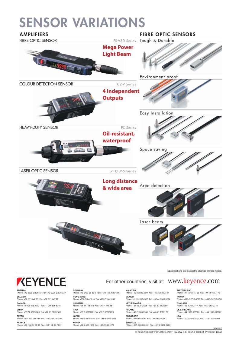
SENSOR VARIATIONSFIBRE OPTIC SENSOR FS-V30 Ser ies
COLOUR DETECTION SENSOR CZ-V Ser ies
HEAVY-DUTY SENSOR PX Ser ies
LASER OPTIC SENSOR LV-H/LV-S Ser ies
Mega Power Light Beam
Oil-resistant, waterproof
4 Independent Outputs
Long distance & wide area
Tough & Durable
Environment-proof
Easy Ins ta l la t ion
Space saving
Area detect ion
Laser beam
AMPLIFIERS FIBRE OPTIC SENSORS