up7 v1 0 corel8 - inicio · j4 j3 j2 j1 program channel inputtransformer up-367, up-247, up-127 y...
TRANSCRIPT

UP-67
UP-127
UP-247
UP-367
N º .Manual de instrucciones
AMPLIFICADOR
Operating instructions
AMPLIFIER
EspañolEspañol
EnglishEnglish
UP
-24
7

ÍNDICE
1. INTRODUCCIÓN. . . . . . . . . . . . . . . . . . . . . . . . . . . . . . . . . . . . . . . . . . . . . . . . . . . . . . . . . . . . . . . . . . . . . . . . 4
2. VISTA FRONTAL . . . . . . . . . . . . . . . . . . . . . . . . . . . . . . . . . . . . . . . . . . . . . . . . . . . . . . . . . . . . . . . . . . . . . . . . 4
3. VISTA POSTERIOR. . . . . . . . . . . . . . . . . . . . . . . . . . . . . . . . . . . . . . . . . . . . . . . . . . . . . . . . . . . . . . . . . . . . . . 5
4. EL SISTEMA DE VENTILACIÓN. . . . . . . . . . . . . . . . . . . . . . . . . . . . . . . . . . . . . . . . . . . . . . . . . . . . . . . . . . . . 9
5. DIAGRAMA DE BLOQUES . . . . . . . . . . . . . . . . . . . . . . . . . . . . . . . . . . . . . . . . . . . . . . . . . . . . . . . . . . . . . . . 10
6. CONFIGURACIÓN DE FÁBRICA . . . . . . . . . . . . . . . . . . . . . . . . . . . . . . . . . . . . . . . . . . . . . . . . . . . . . . . . . . 10
7. CARACTERÍSTICAS TÉCNICAS . . . . . . . . . . . . . . . . . . . . . . . . . . . . . . . . . . . . . . . . . . . . . . . . . . . . . . . . . . 11
8. CERTIFICADO DE GARANTÍA. . . . . . . . . . . . . . . . . . . . . . . . . . . . . . . . . . . . . . . . . . . . . . . . . . . . . . . . . . . . 12
Esp
ESPAÑOL
AMPLIFICADORES UP-367, UP-247, UP-127 y UP-67
3UP-367, UP-247, UP-127 y UP-67 Versión 1.0

1. INTRODUCCIÓN
2. VISTA FRONTAL
Los modelos UP-367, UP-247, UP-127 y UP-67 son amplificadores de 360, 240, 120 y 60 Wats R.M.S.respectivamente.
Indicados para ser utilizados en instalaciones de megafonía, avisos de emergencia, música ambiental yreproducción de la palabra, destacan por su robustez y fiabilidad.
Cada modelo lleva incorporada una protección contra cortocircuito / sobrecarga en la línea de altavoces así comouna protección térmica para evitar averías por recalentamiento excesivo.
Ocupan dos unidades de altura en armarios Rack de 19".
Indica la potencia entregada a la línea. El LED marcado 0 dB refleja el punto donde el amplificador da lamáxima potencia.
Girándolo en el sentido de las agujas del reloj aumentará el volumen del canal de Program. Los botones sonextraíbles
Girándolo en el sentido de las agujas del reloj, aumenta elvolumen del canal de Prioridad.Los botones son extraíbles.
Se ilumina cuando se selecciona el canal de Priority, es decir:cuando se une el pin nº 6 con el pin nº 8 en el conector RJ45 de laEntrada de Prioridad.
Se ilumina cuando actúa la Protección, pudiendo serdebido a una sobrecarga o cortocircuito en la líneade altavoces o bien por un exceso de latemperatura interior
Se ilumina cuando ela m p l i f i c a d o r e s t áfuncionando tanto enalimentación de Redcomo de Batería.
Conecta y desconecta elamplificador solo en casode que esté alimentadopor la RED de 230 Vcc. Sifunciona alimentado porbatería este interruptor noactúa.
INDICADOR DE NIVEL
REGULADOR "MASTER" DE ENTRADA DE PROGRAM
REGULADOR "MASTER" DE ENTRADA DE PRIORITY
INDICADOR DE PRIORIDAD
INDICADOR DE PROTECCIÓN
ENTRADA DEVENTILACIÓNNo obstruir esta entradabajo ningún concepto.
INDICADOR ON/OFF
INTERRUPTOR ON/OFF
2
1
3
4
5
6
7
8
Una vez ajustado el volumen, puedeprotegerse su manipulación extrayendolos botones y colocando en su lugar lostapones suministrados en la bolsa deaccesorios.
Figura 1
ESPAÑOL
AMPLIFICADORES UP-367, UP-247, UP-127 y UP-67
4 UP-367, UP-247, UP-127 y UP-67Versión 1.0
Esp
2
1
3
4
5
6
8
7
UP
-24
7
Fuse
O U T P U T S
0 50V
FAIL
SURETYPAGING
70V 100V16Ω8Ω4Ω
24V
FANPOWERSUPPLY
230V 50/60 Hz
INPUT/OUTPUT CONTACTS
1 2 3 4 5 6 7 8 9
PRIORITYCTRL. INPUT
GND
PRIORITYINPUT
PRIORITYOUTPUT
PROGRAMINPUT
PROGRAMOUTPUT
ON OFF
POWER AMPLIFIER240W RMS (312W IHF)
UP-247
Engineered in EU (Spain)
Made in China
OPTIMUS S.A.
PRI-PRO RJ CONNECTION
6. PRIORITY
8.
METALSHIELD
GND
(WHEN BALANCED)
78
65
3
21
DIPSWITCH CONFIGURATIONON OFF
PRI-PROLINK
SHIELD-GNDLINK
7. Priority ctrl. in6. Audio C5. Audio H4. Priority in
8. Priority ctrl. out
3. Priority out2. Program in1. Program out
SURVEILLANCE
SURVEILLANCE RJ CONNECTION
1. OSC IN2. NC3. OSC OUT 14. PROTECT
5. OSC OUT 26. PRI OUT7. +24VDC OUTPUT8.
METALSHIELD
GND
24V FAIL
O U T P U T S
0 50V 70V 100V4Ω 8Ω 16Ω
SURETY PAGING
Figura 2
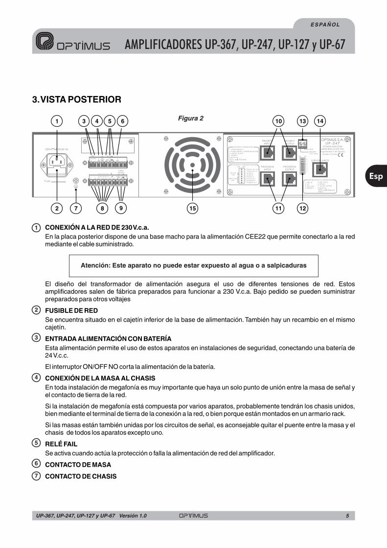
3.VISTA POSTERIOR
CONEXIÓN A LA RED DE 230V.c.a.
FUSIBLE DE RED
ENTRADA ALIMENTACIÓN CON BATERÍA
CONEXIÓN DE LA MASA AL CHASIS
RELÉ FAIL
CONTACTO DE MASA
CONTACTO DE CHASIS
En la placa posterior dispone de una base macho para la alimentación CEE22 que permite conectarlo a la redmediante el cable suministrado.
El diseño del transformador de alimentación asegura el uso de diferentes tensiones de red. Estosamplificadores salen de fábrica preparados para funcionar a 230 V.c.a. Bajo pedido se pueden suministrarpreparados para otros voltajes
Se encuentra situado en el cajetín inferior de la base de alimentación. También hay un recambio en el mismocajetín.
Esta alimentación permite el uso de estos aparatos en instalaciones de seguridad, conectando una batería de24V.c.c.
El interruptor ON/OFF NO corta la alimentación de la batería.
En toda instalación de megafonía es muy importante que haya un solo punto de unión entre la masa de señal yel contacto de tierra de la red.
Si la instalación de megafonía está compuesta por varios aparatos, probablemente tendrán los chasis unidos,bien mediante el terminal de tierra de la conexión a la red, o bien porque están montados en un armario rack.
Si las masas están también unidas por los circuitos de señal, es aconsejable quitar el puente entre la masa y elchasis de todos los aparatos excepto uno.
Se activa cuando actúa la protección o falla la alimentación de red del amplificador.
Atención: Este aparato no puede estar expuesto al agua o a salpicaduras
2
1
3
4
5
6
7
15
5
9
43 6
128
1 13 1410
2 117
5UP-367, UP-247, UP-127 y UP-67 Versión 1.0
Esp
ESPAÑOL
AMPLIFICADORES UP-367, UP-247, UP-127 y UP-67
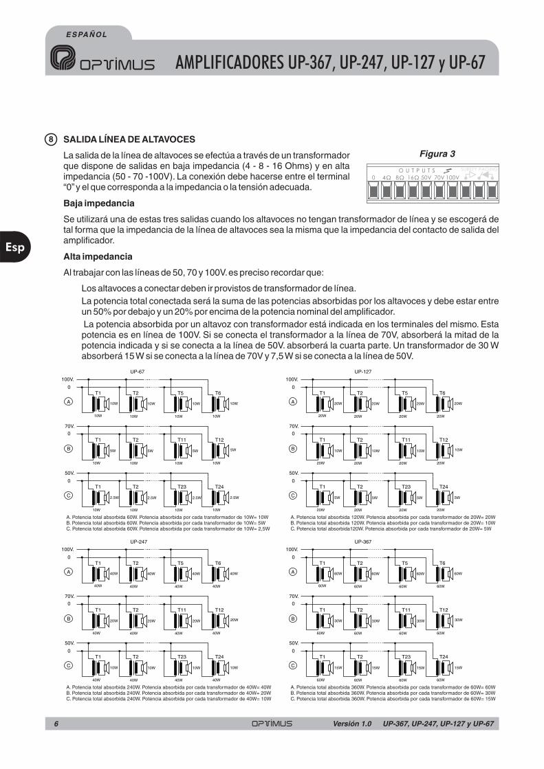
SALIDA LÍNEA DE ALTAVOCES
Baja impedancia
Alta impedancia
La salida de la línea de altavoces se efectúa a través de un transformadorque dispone de salidas en baja impedancia (4 - 8 - 16 Ohms) y en altaimpedancia (50 - 70 -100V). La conexión debe hacerse entre el terminal“0”y el que corresponda a la impedancia o la tensión adecuada.
Se utilizará una de estas tres salidas cuando los altavoces no tengan transformador de línea y se escogerá detal forma que la impedancia de la línea de altavoces sea la misma que la impedancia del contacto de salida delamplificador.
Al trabajar con las líneas de 50, 70 y 100V.es preciso recordar que:
Los altavoces a conectar deben ir provistos de transformador de línea.La potencia total conectada será la suma de las potencias absorbidas por los altavoces y debe estar entreun 50% por debajo y un 20% por encima de la potencia nominal del amplificador.La potencia absorbida por un altavoz con transformador está indicada en los terminales del mismo. Estapotencia es en línea de 100V. Si se conecta el transformador a la línea de 70V, absorberá la mitad de lapotencia indicada y si se conecta a la línea de 50V. absorberá la cuarta parte. Un transformador de 30 Wabsorberá 15W si se conecta a la línea de 70V y 7,5W si se conecta a la línea de 50V.
O U T P U T S
0 50V 70V 100V4Ω 8Ω 16Ω
SURETY PAGING
8
Figura 3
0
0
0
0
0
0
0
0
0
0
0
0
C
C
C
C
B
B
B
B
50V.
50V.
50V.
50V.
70V.
70V.
70V.
70V.
A
A
A
A
100V.
100V.
100V.
100V.
A. Potencia total absorbida 60W. Potencia absorbida por cada transformador de 10W= 10WB. Potencia total absorbida 60W. Potencia absorbida por cada transformador de 10W= 5WC. Potencia total absorbida 60W. Potencia absorbida por cada transformador de 10W= 2,5W
A. Potencia total absorbida 240W. Potencia absorbida por cada transformador de 40W= 40WB. Potencia total absorbida 240W. Potencia absorbida por cada transformador de 40W= 20WC. Potencia total absorbida 240W. Potencia absorbida por cada transformador de 40W= 10W
A. Potencia total absorbida 120W. Potencia absorbida por cada transformador de 20W= 20WB. Potencia total absorbida 120W. Potencia absorbida por cada transformador de 20W= 10WC. Potencia total absorbida120W. Potencia absorbida por cada transformador de 20W= 5W
A. Potencia total absorbida 360W. Potencia absorbida por cada transformador de 60W= 60WB. Potencia total absorbida 360W. Potencia absorbida por cada transformador de 60W= 30WC. Potencia total absorbida 360W. Potencia absorbida por cada transformador de 60W= 15W
10W
40W
20W
60W
10W
40W
20W
60W
10W
40W
20W
60W
T1
T1
T1
T1
T1
T1
T1
T1
T1
T1
T1
T1
10W
40W
20W
60W
2.5W
10W
5W
15W
5W
20W
10W
30W
10W
40W
20W
60W
10W
40W
20W
60W
10W
40W
20W
60W
10W
40W
20W
60W
2.5W
10W
5W
15W
5W
20W
10W
30W
UP-67
UP-247
UP-127
UP-367
T2
T2
T2
T2
T2
T2
T2
T2
T2
T2
T2
T2
10W
40W
20W
60W
10W
40W
20W
60W
10W
40W
20W
60W
T23
T23
T23
T23
T11
T11
T11
T11
T5
T5
T5
T5
10W
40W
20W
60W
2.5W
10W
5W
15W
5W
20W
10W
30W
2.5W
10W
5W
15W
5W
20W
10W
30W
10W
40W
20W
60W
10W
40W
20W
60W
10W
40W
20W
60W
10W
40W
20W
60W
T24
T24
T24
T24
T12
T12
T12
T12
T6
T6
T6
T6
ESPAÑOL
AMPLIFICADORES UP-367, UP-247, UP-127 y UP-67
Esp
6 UP-367, UP-247, UP-127 y UP-67Versión 1.0

RELÉ AUXILIAR DE SEGURIDAD DE AVISOS
CANAL DE PRIORIDAD y CANAL DEPROGRAMA.
Conmuta cuando se activa el contacto de prioridad del canal PRIORITY.
Los dos canales de entrada (PROGRAM yPRIORITY) utilizan 4 conectores del tipo RJ45conectados en paralelo 2 a 2. De este modo,pueden proporcionar señal a otras etapas depotencia (ver figura 4).
Para su conexión (ver figura 5) debe utilizarsecable STP de Cat 5. La principal característicade este tipo de cable es su muy bajaimpedancia, de manera que permite unarespuesta frecuencial excepcionalmenteplana incluso para largas distancias,cumpl iendo evidentemente con lasprestaciones de CMRR y "Crosstalk"requeridas para audio analógico.
Las entradas de señal son no balanceadas ytienen una sensibilidad de 0 dBu (775mV).
El pin nº 3 proporciona una tensión de 24Vcc que puede utilizarse para alimentar dispositivos de bajo consumo.La corriente máxima suministrada es de 200 mA.en cada canal.
En el canal de PRIORITY, al unir el pin nº 6 con el pin nº 8 se activa el sistema de prioridad, y se activa el reléauxiliar de seguridad de avisos (ver figura 2, número 9). A través del pin número 6 del conector PRIORITYOUTPUT, puede transmitirse el control de prioridad a otras etapas de potencia, siempreen función de la posición de los dipswitchs 7 y 8 (Ver punto 12 del apartado 3. VISTAPOSTERIOR )
Opcionalmente se puede acoplar a estas entradas un transformadorsimetrizador (T700) cortando los puentes J1 y J2 para la entrada deprograma, y J3 y J4 para la entrada de prioridad, conectando lostransformadores como indica la figura 6.
Fuse
O U T P U T S
0 50V
FAIL
SURETYPAGING
70V 100V16Ω8Ω4Ω
24V
FANPOWERSUPPLY
230V 50/60 Hz
I NPUT /OUT PUT CONT ACT S
1 2 3 4 5 6 7 8 9
PRIORITYCTRL. INPUT
GND
PRIORITYINPUT
PRIORITYOUTPUT
PROGRAMINPUT
PROGRAMOUTPUT
ON OFF
POWER AMPLIFIER240W RMS (312W IHF)
UP-247
Engineered in EU (Spain)
Made in China
OPTIMUS S.A.
PRI-PRO RJ CONNECTION
6. PRIORITY
8.
METALSHIELD
GND
(WHEN BALANCED)
78
65
3
21
DIPSWITCH CONFIGURATIONON OFF
PRI-PROLINK
SHIELD-GNDLINK
7. Priority ctrl. in6. Audio C5. Audio H4. Priority in
8. Priority ctrl. out
3. Priority out2. Program in1. Program out
SURVEILLANCE
SURVEILLANCE RJ CONNECTION
1. OSC IN2. NC3. OSC OUT 14. PROTECT
5. OSC OUT 26. PRI OUT7. +24VDC OUTPUT8.
METALSHIELD
GND
24V FAIL
O U T P U T S
0 50V 70V 100V4Ω 8Ω 16Ω
SURETY PAGING
Pin number 1: SIGNAL H
Pin number 2: SIGNAL C (if the input is balanced)
Pin number 3: +24VDC
Pin number 6: PRIORITY contact
Pin number 8:
Shield
Pin number 1: SIGNAL H
Pin number 2: SIGNAL C (if the input is balanced)
Pin number 3: +24VDC
Pin number 8:
Shield
PRIORITY CHANNEL CONNECTION
PROGRAM CHANNEL CONNECTION
GND
GND
1
8
Figura 6
Figura 5
N.C. N.C.600 Ohm 600 Ohm
T-700
9
10 11 Figura 4
PRIORITY CHANNELINPUT TRANSFORMER
J4
J3
J2
J1 PROGRAM CHANNELINPUT TRANSFORMER
7UP-367, UP-247, UP-127 y UP-67 Versión 1.0
Esp
ESPAÑOL
AMPLIFICADORES UP-367, UP-247, UP-127 y UP-67

Fuse
O U T P U T S
0 50V
FAIL
SURETYPAGING
70V 100V16Ω8Ω4Ω
24V
FANPOWERSUPPLY
230V 50/60 Hz
INPUT/OUTPUT CONTACTS
1 2 3 4 5 6 7 8 9
PRIORITYCTRL. INPUT
GND
PRIORITYINPUT
PRIORITYOUTPUT
PROGRAMINPUT
PROGRAMOUTPUT
ON OFF
POWER AMPLIFIER240W RMS (312W IHF)
UP-247
Engineered in EU (Spain)
Made in China
OPTIMUS S.A.
PRI-PRO RJ CONNECTION
6. PRIORITY
8.
METALSHIELD
GND
(WHEN BALANCED)
78
65
3
21
DIPSWITCH CONFIGURATIONON OFF
PRI-PROLINK
SHIELD-GNDLINK
7. Priority ctrl. in6. Audio C5. Audio H4. Priority in
8. Priority ctrl. out
3. Priority out2. Program in1. Program out
SURVEILLANCE
SURVEILLANCE RJ CONNECTION
1. OSC IN2. NC3. OSC OUT 14. PROTECT
5. OSC OUT 26. PRI OUT7. +24VDC OUTPUT8.
METALSHIELD
GND
24V FAIL
O U T P U T S
0 50V 70V 100V4Ω 8Ω 16Ω
SURETY PAGING
DIPSWITCH DE CONFIGURACIÓN
PRIORITY CONTROL OUT (dipswitch núm.8)
PRIORITY CONTROL IN (dipswitch núm.7)
PRI-PRO LINK (dipswitchs núm.5 y 6)
SHIELD - GND LINK (dipswitchs núm.1,2,3 y 4)
REGLETA PRIORITY CONTROL
En posición OFF, deshabilita el contacto deprioridad del conector RJ PRIORITY OUTPUT.
En posición OFF, deshabilita el contacto deprioridad del conector RJ PRIORITY INPUT.
Estos dos dipswitchs unen internamente la señalde audio H y la señal de audio C (cuando laentrada es balanceada ) presentes en la salidade prioridad (PRIORITY OUTPUT) con laentrada de programa (PROGRAM INPUT).Normalmente están en posición OFF (señales deaudio separadas). Para unirlas debe situarse eldipswitch correspondiente en ON.
Estos 4 dipswitchs permiten separar la pantalladel cable de la masa interna del aparato paracada uno de los conectores RJ-45.Normalmenteestán en posición ON (pantalla y masa delaparato unidas).Para separarlas debe situarse eldipswitch correspondiente en OFF.
Estos contactos permitenla act ivac ión de laprioridad, facilitando elc a b l e a d o d e l ainstalación.
El diagrama de bloquesde la figura 8 muestra unejemplo de instalacióntípica.
12
13
OUTPUT - INPUT DIAGRAM
Figura 6
Figura 7
Figura 8
zone 1A
zone 1B
zone 2
zone 3
zone 4
zone 5
UP-127PM-612/0
MIC
ZONES SELECTOR
C610PAL
UP-127
UP-127
UP-127
UP-127
UP-127
Priority inputRJ connector
Priority inputRJ connector
Priority inputRJ connector
Priority inputRJ connector
Priority inputRJ connector
Priority inputRJ connector
Priority controlinput contact
Priority controlinput contact
Priority controlinput contact
Priority controlinput contact
Priority controlinput contact
Priority controlinput contact
Priority outputRJ connector
Priority outputRJ connector
Priority outputRJ connector
Priority outputRJ connector
Priority outputRJ connector
8 pins RJ45connectors
Priority
PRI-PRO LINK
SHIELD-GNDLINK
ON OFF
Zone 2, 3, 4 and 5 UP-127 configuration
PRI-PRO LINK
SHIELD-GNDLINK
ON OFF
Zone 1B configurationUP-127
PRI-PRO LINK
SHIELD-GNDLINK
ON OFF
Zone 1A configurationUP-127
ESPAÑOL
AMPLIFICADORES UP-367, UP-247, UP-127 y UP-67
Esp
8 UP-367, UP-247, UP-127 y UP-67Versión 1.0
To power unit
AUDIO H
PRIORITY CTRL.
PRIORITYCONTROL INPUT
GND
PRIORITYINPUT
PROGRAMINPUT
SHLD
SHLD
AUDIO H
SW 7 SW 8
SW 4 SW 3
SW 5
SW 2 SW 1
SW 6
AUDIO C
AUDIO C
PROGRAMOUTPUT
SHLD
AUDIO H
AUDIO C
AUDIO H
PRIORITY CTRL.
PRIORITYOUTPUT
SHLD
AUDIO C

CONECTOR SURVEILLANCE
SALIDA DEVENTILACIÓN
No obstruir esta salida bajo ningúnconcepto.
UP-367 y UP-247
UP-127
Se utiliza para interconectar el amplificador conla carta supervisora de líneas, cuando searequerimiento de la instalación.
Para la conexión utilice conectores RJ45 concarcasa metálica (ver figura 9).
Equipada con un ventilador frontal yuno posterior. El frontal se activa sila temperatura interna alcanza los65º. El posterior se activa cuando lat e m p e r a t u r a i n t e r i o r d e lamplificador alcanza los 100ºC.Esto sólo debe ocurr i r ensituaciones extremas ya que encondiciones normales el equipoestá dimensionado para nonecesi tar la act ivación delventilador posterior.
Si la temperatura interna delaparato superase los 110ºC seactivaría la protección del aparato.
Equipada con un ventilador frontal.Se activa cuando la temperaturainterior alcanza los 100ºC.Esto sólodebe ocurr ir en situacionesextremas ya que en condicionesn o r m a l e s e l e q u i p o e s t ádimensionado para no necesitar laactivación del ventilador.
Si la temperatura interna delaparato superase los 110ºC seactivaría la protección del aparato.
Para sustituir los ventiladores encaso de avería, siga las figuras 10 y11.
4. EL SISTEMA DE VENTILACIÓN
14 Pin number 1: OSCILLATION INPUT
: OSCILLATION OUTPUT 1
: PROTECTION OUTPUT
: OSCILLATION OUTPUT 2
Pin number 6: PRIORITY OUTPUT
Pin number 7: +24VDC OUTPUT
8:
Shield
Pin number 3
Pin number 4
Pin number 5
Pin number
GND
1
8
1
8
JP2(puente interno)
15
Figura 10
Figura 9
Figura 11
9UP-367, UP-247, UP-127 y UP-67 Versión 1.0
Esp
ESPAÑOL
AMPLIFICADORES UP-367, UP-247, UP-127 y UP-67
ONOFF
SURVEILLANCE RJ45
CONNECTION
7
8
65
2
3
1
1. OSCIN
2. NC3. OSCOUT 1
4. PROTECT
5. OSCOUT 2
6. PRI OUT7. +24VDC
OUTPUT
8.METALSHIELD
GND
DIPSWITCH
CONFIGURATION
ON
OFF
8. Priority ctrl. out
7. Priority ctrl. in
6. Audio C5. Audio H4. Priority In
3. Priority out
2. Programin
1. Programout
PRI-PROLINKSHIELD-GND
LINK
1. AUDIOSIGNAL H
2. AUDIOSIGNAL C
(WHEN
BALANCED)
3. +24 VDCOUTPUT
6. PRIORITY8.METALSHIELD
GND
PRIORITY &PROGRAM
RJ45 CONNECTION
SURVEILLANCE
PRIORITYINPUT
PRIORITYOUTPUT
PROGRAMINPUT
PROGRAMOUTPUT
PRIORITYCTRL. INPUT
GND
OPTIMUS S.A.
UP-247
POWER AM
PLIFIER
240WRM
S (312WIHF)
Engineering &Q.A.
FromEU (Spain)M
ade in China
UP
-24
7
0
50V
70V
100V
4Ω
8Ω
16Ω
SPEAKERSLINEOUTPUT
POWERSTAGE
PRIORITYCONTROL
INPUT
MASTERPRIORITY
MASTERPROGRAM
PRI-PROLINK
PROGRAM
PRIORITY
PROTECTION
PRIORITY OUTPUT
PRIORITY INPUT
PROGRAM OUTPUT
PROGRAM INPUT
SURETYPAGING
FAIL
SURVEILLANCE
Priority & Control Signal
Audio
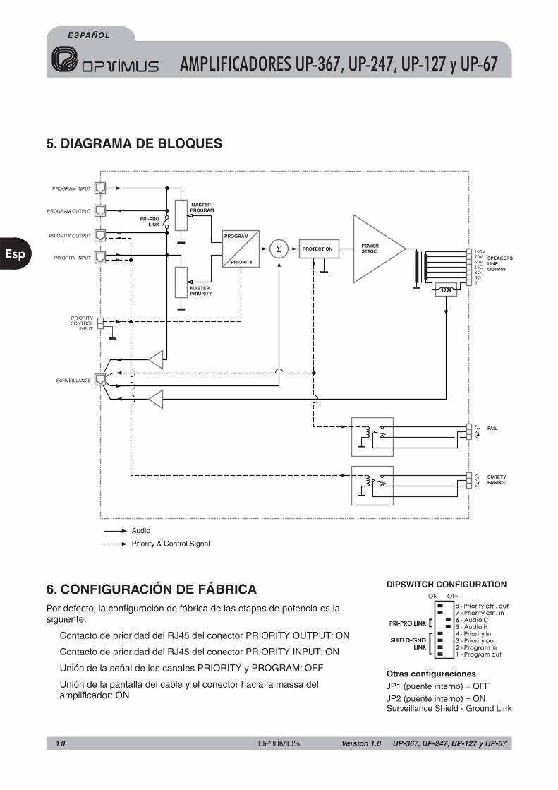
5. DIAGRAMA DE BLOQUES
6. CONFIGURACIÓN DE FÁBRICAPor defecto, la configuración de fábrica de las etapas de potencia es lasiguiente:
Contacto de prioridad del RJ45 del conector PRIORITY OUTPUT: ON
Contacto de prioridad del RJ45 del conector PRIORITY INPUT: ON
Unión de la señal de los canales PRIORITY y PROGRAM: OFF
Unión de la pantalla del cable y el conector hacia la massa delamplificador: ON
ON OFF
PRI-PRO LINKPRI-PRO LINK
SHIELD-GNDLINK
SHIELD-GNDLINK
7 - Priority ctrl. in7 - Priority ctrl. in8 - Priority ctrl. out8 - Priority ctrl. out
3 - Priority out3 - Priority out
DIPSWITCH CONFIGURATION
Otras configuracionesJP1 (puente interno) = OFF
JP2 (puente interno) = ONSurveillance Shield - Ground Link
ESPAÑOL
AMPLIFICADORES UP-367, UP-247, UP-127 y UP-67
Esp
1 0 UP-367, UP-247, UP-127 y UP-67Versión 1.0

7. CARACTERÍSTICAS TÉCNICAS
Potencia de salida R.M.S.
Potencia de salida I.H.F.
Distorsión armónica total
Ancho de banda
Relación señal/ruido
Entradas
Sensibilidad entradas
Salida línea de altavoces
Controles
Alimentación Red
Alimentación Batería
Consumo vacío
Consumo plena carga
Dimensiones (mm)
Protección sobrecalentamiento
Temperatura de activacióndel ventilador
Unidades de rack
Peso
Acabados
120 W60 W
UP-127UP-67
240 W
UP-247
360 W
482 W
UP-367
162 W82 W 312 W
< 0,5 % (1 kHz)< 0,5 % (1 kHz) < 0,5 % (1 kHz) < 0,65 % (1 kHz)
50 ~ 18.000 Hz (±3 dB)
1 programa (0 dBu), 1 prioridad (0 dBu)
775 mV (programa y prioridad)
100 V, 70 V, 50 V / 4, 8, 16 ohms
Volumen de programa y de prioridad
230 V.c.a.
7,5 VA16 VA 9,2 VA 16 VA
253 VA138 VA
-
460 VA 736 VA
482,6 (w) x 88,8 (h) x 368,5 (d)
Placa frontal en hierro pintada negra. Tapa en hierro pintada negra.
> 80 dB
24 V.c.c.
110º C95º C
Ventilador frontal:100º C*Ventilador frontal: 65º C
Ventilador posterior: 100º C*Ventilador frontal: 65º C
Ventilador posterior: 100º C*
2
10 kg8,6 kg 13,6 kg 15,7 kg
(*) En condiciones normales el equipo está dimensionadopara no necesitar la activación del ventilador.
11UP-367, UP-247, UP-127 y UP-67 Versión 1.0
Esp
ESPAÑOL
AMPLIFICADORES UP-367, UP-247, UP-127 y UP-67

7. CERTIFICADO DE GARANTÍA1. La empresa OPTIMUS S.A. garantiza que sus productos se encuentranlibres de defectos en materiales y de mano de obra en el momento de suentrega original al comprador.
2. La empresa OPTIMUS S.A. concede a sus productos, conforme a lascondiciones aquí descritas, una garantía de dos (2) años a partir de la fecha deadquisición del producto por el comprador.Si, dentro de este plazo de garantía,se producen defectos que no sean debidos a razones mencionadas bajo elpunto 2, la empresa OPTIMUS S.A. reemplazará o reparará el aparatoutilizando piezas de recambio equivalentes, nuevas o reconstruidas, segúncriterio propio. Si se aplican piezas de recambio que constituyen una mejoradel aparato, la empresa OPTIMUS S.A. se reserva el derecho de cargar elcoste adicional de estos componentes al cliente.
3. No se concederán prestaciones de garantía distintas a las citadas.
4. Para la utilización de los derechos de garantía será requisito indispensablepresentar la factura de compra original o el certificado de garantía.
2.DISPOSICIONES DE GARANTÍA
1. Si el producto tuviera que ser modificado o adaptado para cumplir con losrequisitos locales en cuanto a técnica o seguridad, si no se trata del país para elcual el producto fue concebido y fabricado originalmente, ello no se consideracomo defecto de material o de fabricación. Por lo demás, la garantía nocomprende la realización de estas modificaciones o adaptaciones,independientemente de si éstas hayan sido ejecutadas debidamente o no.
OPTIMUS S.A. tampoco asumirá costes en el marco de la garantía por estetipo de modificaciones.
2. La garantía no dará derecho a inspección o mantenimiento gratuito oreparación del aparato, particularmente si los defectos son debidos a usoinapropiado. Los derechos de garantía tampoco abarcan defectos en piezasde desgaste que sean debidos a un desgaste normal.Piezas de desgaste son,en particular, potenciómetros, interruptores/teclas, y piezas similares.
3. La garantía no abarca los defectos en el equipo causados por:Abuso o uso incorrecto del aparato para fines distintos a los previstos, enincumplimiento de las instrucciones de servicio y de mantenimientoespecificadas en el Manual y/o InstruccionesTécnicas del equipo.
Conexión o uso del producto de una manera que no corresponda a losrequisitos técnicos o de seguridad del país en el cual se utiliza el aparato.
Instalación en condiciones distintas a los indicados en el Manual y/oInstruccionesTécnicas.
Deficiencia o interrupciones tensión eléctrica o defectos de instalación queimpliquen uso en condiciones anormales.
Daños ocasionados por otros equipos interconectados al producto.
El uso o instalación de Software (programas), interfaces, partes osuministros no proporcionados y/o autorizados por OPTIMUS S.A.
La no utilización de los embalajes originales para su transporte.
Daños causados por fuerza mayor u otras causas no imputables aOPTIMUS S.A.
4. No están cubiertos por esta garantía los siguientes elementos:
Todas las superficies de plástico y todas las piezas expuestas al exteriorque hayan sido rayadas o dañadas debido al uso normal o anormal.
Las roturas, golpes, daños por caídas o ralladuras causadas por trasladosde cualquier naturaleza.
Defectos de daños derivados de pruebas, uso, mantenimiento, instalacióny ajustes inapropiados, o derivados de cualquier alteración o modificaciónde cualquier tipo no realizada por en Servicio Autorizado por OPTIMUSS.A.en cumplimiento de esta garantía.
Los daños personales o a la propiedad que pudieran causar el usoindebido del equipo, incluyendo la falta de mantenimiento.
5. La garantía carecerá de validez cuando se observe:
Enmiendas o tachaduras en los datos del certificado de garantía o facturade compra.
Falta de factura original o falta de fecha en la misma.
Falta de número de serie o lote en el equipo.
6 En el caso de ordenadores P.C., la garantía no cubrirá la eliminación de
virus informáticos, restauración de programas por este motivo o lareinstalación del disco provocada por el borrado del mismo.
7. Los derechos de garantía se anulan si el producto ha sido reparado oabierto por un personal no autorizado OPTIMUS S.A.o por el propio cliente.
8. Si la empresa OPTIMUS S.A. estableciera al comprador del aparato quelos daños presentados no dan derecho a la reclamación de la garantía, loscostes de las prestaciones de revisión por parte de la empresa OPTIMUS S.A.correrán a cargo del cliente.
9. Los productos sin derechos de garantía sólo se repararán contra pago delos gastos por el cliente. En caso de ausencia de derechos de garantía,OPTIMUS S.A. informará al cliente al respecto.Si, en un plazo de 6 semanas apartir de esta comunicación, no recibimos ninguna orden de reparación escritaconfirmando la aceptación de los gastos, OPTIMUS S.A. devolverá el aparatoen cuestión al cliente. En este caso, los gastos de transporte y embalaje sefacturarán por separado y se cobrarán contra reembolso. En caso deexpedición de una orden de reparación, confirmando la asunción de losgastos, los gastos de transporte y de embalaje se facturarán adicionalmente,igualmente por separado.
10. En caso de necesidad de traslado al Centro de Servicio Autorizado, eltransporte será realizado por el responsable de la garantía, y serán a su cargolos gastos de flete y seguro.
11. En caso de falla, OPTIMUS S.A. asegura al comprador la reparación y/oreposición de partes para su correcto funcionamiento en un plazo no mayor a30 días.No obstante, se deja aclarado que el plazo usual no supera los 30 días.
12. Todas las piezas o productos sustituidos al amparo de los servicios engarantía pasarán a ser propiedad de OPTIMUS S.A.
3.TRANSFERENCIA DE LA GARANTÍA
La garantía se concede únicamente para el comprador original (clienteprincipal) y es intransferible. Con excepción de la empresa OPTIMUS S.A.,ningún tercero (comerciantes, etc.) está autorizado a conceder garantíaadicionales en nombre de la empresa OPTIMUS S.A.
4.RECLAMACIONES POR DAÑOSY PERJUICIOS
En caso de que OPTIMUS S.A. no pueda proporcionar un servicio de garantíaadecuado, el comprador no tendrá ningún derecho a reclamar indemnizaciónalguna por daños y perjuicios consecuentes.La responsabilidad de la empresaOPTIMUS S.A.se limita en todo caso al precio de facturación del producto.
5. RELACIÓN CON OTROS DERECHOS DE GARANTÍA Y CON ELDERECHO NACIONAL
1. Mediante esta garantía no se afecta a los derechos del comprador frente alvendedor deducidos del contrato de compraventa concluido.
2. Las presentes condiciones de garantía de la empresa OPTIMUS S.A. sonválidas siempre que no contradigan el derecho nacional correspondiente enrelación con las disposiciones de garantía.
3. OPTIMUS S.A. asegura que este producto cumple con las normas deseguridad vigentes en el país.
ESTA DECLARACIÓN DE GARANTÍA LIMITADA ES LA GARANTÍAEXCLUSIVA OFRECIDA POR OPTIMUS S.A. SE EXCLUYE TODA OTRAGARANTÍA EXPLÍCITA O IMPLÍCITA, INCLUIDAS LAS GARANTÍAS DECOMERCIALIDAD Y APTITUD A UN FIN DETERMINADO. (EXCEPTOCUANDO DICHAS GARANTÍAS SEAN REQUERIDAS POR UNA LEYAPLICABLE). NINGUNA GARANTÍA, YA SEA EXPLÍCITA O IMPLÍCITA, SEAPLICARÁTRAS LA FINALIZACIÓN DEL PERIODO DE GARANTÍA.
OPTIMUS S.A.Servicio Post VentaC/ Barcelona 10117003 - GIRONATel. 902 151 96 / 972 203 300Fax. 972 21 84 13e-mail : [email protected] 1999/44/CE
�
�
�
�
�
�
�
�
�
�
�
�
�
�
�
ESPAÑOL
AMPLIFICADORES UP-367, UP-247, UP-127 y UP-67
Esp
1 2 UP-367, UP-247, UP-127 y UP-67Versión 1.0

LIST OF CONTENTS
1. INTRODUCTION . . . . . . . . . . . . . . . . . . . . . . . . . . . . . . . . . . . . . . . . . . . . . . . . . . . . . . . . . . . . . . . . . . . . . . 14
2. FRONT VIEW. . . . . . . . . . . . . . . . . . . . . . . . . . . . . . . . . . . . . . . . . . . . . . . . . . . . . . . . . . . . . . . . . . . . . . . . . 14
3. REAR VIEW. . . . . . . . . . . . . . . . . . . . . . . . . . . . . . . . . . . . . . . . . . . . . . . . . . . . . . . . . . . . . . . . . . . . . . . . . . 15
4. VENTILANTION SYSTEM . . . . . . . . . . . . . . . . . . . . . . . . . . . . . . . . . . . . . . . . . . . . . . . . . . . . . . . . . . . . . . . 19
5. BLOCK DIAGRAM . . . . . . . . . . . . . . . . . . . . . . . . . . . . . . . . . . . . . . . . . . . . . . . . . . . . . . . . . . . . . . . . . . . . . 20
6. FACTORY SETUP . . . . . . . . . . . . . . . . . . . . . . . . . . . . . . . . . . . . . . . . . . . . . . . . . . . . . . . . . . . . . . . . . . . . . 20
7. TECHNICAL SPECIFICATIONS . . . . . . . . . . . . . . . . . . . . . . . . . . . . . . . . . . . . . . . . . . . . . . . . . . . . . . . . . . 21
8. GUARANTEE. . . . . . . . . . . . . . . . . . . . . . . . . . . . . . . . . . . . . . . . . . . . . . . . . . . . . . . . . . . . . . . . . . . . . . . . . 22
13UP-367, UP-247, UP-127 and UP-67 Version 1.0
Eng
ENGLISH
AMPLIFIERS UP-367, UP-247, UP-127 and UP-67

1. INTRODUCTION
2.FRONTVIEW
Models UP-367, UP-247, UP-127 and UP-67 are amplifiers with an output of 360, 240, 120 and 60 Wats R.M.S.respectyvely.
Suitable for use with public address systems, emergency announcements, background music and reproduction ofspeech, they are remarkably strong and reliable.
Each model features an in-built circuit to protect against short circuit or overloading in the speaker line as well as atermal protection circuit to prevent damage caused by overheating.
They occupy two standard 19” rack units.
This indicates how much power is being fed to the line. The LED marked 0 dB shows the point at which theamplifier provides maximum power.
Turning this clockwise will increase the volume of the program channel.These knobs are removable.
Turning this clockwise will increase the volume of the prioritychannel.These knobs are removable.
This lights up when the priority channel is selected i.e.when pin no.6 is linked to pin no.8 at the priority input RJ45 connector.
This lights up when the protection circuit has been activated,either as a result of an overload or short circuit in the speaker lineor overheating inside the unit.
This lights up when theamplifier is connected tothe mains supply or isbeing powered by abattery source.
This turns the amplifier onand o f f when i t i sconnected to a mainssupply of 230V.a.c. Thisswitch does not have anyeffect when the unit isbattery powered.
LEVEL INDICATOR
PROGRAM INPUT 'MASTER' REGULATOR
PRIORITY INPUT 'MASTER' REGULATOR
PRIORITY INDICATOR
PROTECTION INDICATOR
VENTILATION INPUTThis must be keptunobstructed at alltimes.
ON/OFF INDICATOR
ON/OFF SWITCH.
AMPLIFIERS UP-367, UP-247, UP-127 and UP-67
Eng
2
1
3
4
5
6
7
8
Once the volume has been adjusted thesystem can be protected by removing thebuttons and replacing them with thecovers supplied in the bag of accessories.
Figure 1
ENGLISH
1 4 UP-367, UP-247, UP-127 and UP-67Version 1.0
2
1
3
4
5
6
8
7
UP
-24
7

3.REARVIEW
CONNECTIONTO 230V a.c.MAINS SUPPLY
POWER FUSE
BATTERY POWER INPUT
CONNECTION OFTHE SIGNAL MASSTOTHE FRAME
FAIL RELAY
GROUND CONTACT
CHASIS CONTACT
The rear panel incorporates a CEE 22 plug which allows the amplifier to be connected to a mains supply via thecable supplied.
The power transformer is designed to be able to operate with different voltages. These amplifiers are factorypreset at 230V a.c.but on demand can also be prepared for use with other voltages.
This is contained in the compartment located under the power inlet. This compartment also contains a sparefuse.
This allows for these amplifiers to be used in safety installations through their connection to a 24V d.c.battery.
The ON/OFF switch does NOT cut off the battery power supply.
In all loudspeaker systems it is very important to have only one connection point between the signal mass andthe power supply ground terminal.
If the loudspeaker assembly is made up of several units, the frames will probably be connected either throughthe power supply ground terminal or because they are rack mounted.
If the signals are also connected through the signal circuits, it is advisable to remove the jumpers between thesignal mass and the frame of all the units but one.
It is activated when the protection of the amplifier fails or when the power suplí of the amplifier is off.
Attention: Keep the unit away from water or splatterings of any type
PRIORITYCTRL. INPUT
GND
PRIORITYINPUT
PRIORITYOUTPUT
PROGRAMINPUT
PROGRAMOUTPUT
ON OFF
POWER AMPLIFIER240W RMS (312W IHF)
UP-247
Engineered in EU (Spain)
Made in China
OPTIMUS S.A.
PRI-PRO RJ CONNECTION
6. PRIORITY
8.
METALSHIELD
GND
(WHEN BALANCED)
78
65
3
21
DIPSWITCH CONFIGURATIONON OFF
PRI-PROLINK
SHIELD-GNDLINK
7. Priority ctrl. in6. Audio C5. Audio H4. Priority in
8. Priority ctrl. out
3. Priority out2. Program in1. Program out
SURVEILLANCE
SURVEILLANCE RJ CONNECTION
1. OSC IN2. NC3. OSC OUT 14. PROTECT
5. OSC OUT 26. PRI OUT7. +24VDC OUTPUT8.
METALSHIELD
GND
24V FAIL
O U T P U T S
0 50V 70V 100V4Ω 8Ω 16Ω
SURETY PAGING
Fuse
O U T P U T S
0 50V
FAIL
SURETYPAGING
70V 100V16Ω8Ω4Ω
24V
FANPOWERSUPPLY
230V 50/60 Hz
INPUT/OUTPUT CONTACTS
1 2 3 4 5 6 7 8 9
Figure 2
2
1
3
4
5
6
7
15
5
9
43 6
128
1 13 1410
2 117
Eng
15UP-367, UP-247, UP-127 and UP-67 Version 1.0
ENGLISH
AMPLIFIERS UP-367, UP-247, UP-127 and UP-67

LOUDSPEAKERS LINE OUT
Low impedance
High impedance
The loudspeakers line out is effected by means of a transformer that haslow impedance outputs (4 – 8 – 16 Ohms) and high impedance outputs(50 – 70 – 100V).The connection must be made between terminal “0” and the terminalcorresponding to the appropriate impedance or voltage.
One of these three outputs will be used when the loudspeakers do not have a line transformer, and it will beselected in such a way that the loudspeaker line impedance is the same as the impedance of the amplifi eroutput contact.
When working with the 50, 70 and 100V lines, it should be remembered that:The loudspeakers to be connected must have a line transformer.The total connected power will be the sum of the power absorbed by the loudspeakers and this must bebetween 50% below and 20% above the rated power of the amplifi er.The power absorbed by a loudspeaker with a transformer is indicated on its terminals.This power is on the100V line. If the transformer is connected to the 70V line, it will absorb half the indicated power, and if it isconnected to the 50V line, it will absorb a quarter of this power. A 30W transformer will absorb 15W if it isconnected to the 70V line and 7.5W if it is connected to the 50V line.
O U T P U T S
0 50V 70V 100V4Ω 8Ω 16Ω
SURETY PAGING
8
Figure 3
0
0
0
0
0
0
0
0
0
0
0
0
C
C
C
C
B
B
B
B
50V.
50V.
50V.
50V.
70V.
70V.
70V.
70V.
A
A
A
A
100V.
100V.
100V.
100V.
A. Total input power 60W. Power absorbed by each 10W transformer = 10WB. Total input power 60W. Power absorbed by each 10W transformer = 5WC. Total input power 60W. Power absorbed by each 10W transformer = 2.5W
A. Total input power 120W. Power absorbed by each 20W transformer = 20WB. Total input power 120W. Power absorbed by each 20W transformer = 10WC. Total input power 120W. Power absorbed by each 20W transformer = 5W
A. Total input power 240W. Power absorbed by each 40W transformer = 40WB. Total input power 240W. Power absorbed by each 40W transformer = 20WC. Total input power 240W. Power absorbed by each 40W transformer = 10W
A. Total input power 360W. Power absorbed by each 60W transformer = 60WB. Total input power 360W. Power absorbed by each 60W transformer = 30WC. Total input power 360W. Power absorbed by each 60W transformer = 15W
10W
40W
20W
60W
10W
40W
20W
60W
10W
40W
20W
60W
T1
T1
T1
T1
T1
T1
T1
T1
T1
T1
T1
T1
10W
40W
20W
60W
2.5W
10W
5W
15W
5W
20W
10W
30W
10W
40W
20W
60W
10W
40W
20W
60W
10W
40W
20W
60W
10W
40W
20W
60W
2.5W
10W
5W
15W
5W
20W
10W
30W
UP-67
UP-247
UP-127
UP-367
T2
T2
T2
T2
T2
T2
T2
T2
T2
T2
T2
T2
10W
40W
20W
60W
10W
40W
20W
60W
10W
40W
20W
60W
T23
T23
T23
T23
T11
T11
T11
T11
T5
T5
T5
T5
10W
40W
20W
60W
2.5W
10W
5W
15W
5W
20W
10W
30W
2.5W
10W
5W
15W
5W
20W
10W
30W
10W
40W
20W
60W
10W
40W
20W
60W
10W
40W
20W
60W
10W
40W
20W
60W
T24
T24
T24
T24
T12
T12
T12
T12
T6
T6
T6
T6
ENGLISH
AMPLIFIERS UP-367, UP-247, UP-127 and UP-67
Eng
1 6 UP-367, UP-247, UP-127 and UP-67Version 1.0

SURETY PAGING RELAY
PRIORITY CHANNEL AND PROGRAMCHANNEL.
This connects when the PRIORITY channel priority contact is activated.
The two input channels (PROGRAM andPRIORITY) use four RJ45 connectors whichare connected in pair and parallel formation.This means that they can provide a signal forother boosting stages (see figure 4).
The amplifier should be connected using anSTP Cat-5 cable (see figure 5). This cable isrenowned for its very low impedance, whichmeans that it allows for an exceptionally flatfrequential response even over long distancesand obviously meets with CMRR and crosstalkrequirements for analogic audio applications.
The signal inputs are not balanced and have asensitivity of 0 dBU (775mV).
Pin no. 3 provides a voltage of 24 V.d.c., whichcan be used to power low consumptiondevices.The maximum current supplied is 200mA in each channel.
In the PRIORITY channel, when pin no.6 is linked to pin no.8 the priority system and the surety paging relay areactivated (see figure 2, no.9).The priority control can be transmitted to other boosting stages through pin no.6 ofthe PRIORITY OUTPUT connector, depending on the position of dipswitches 7 and 8(See section 3.REARVIEW, no.12).
Another option is to connect a symmetric transformer (T700) to these inputs andremove the J1 and J2 jumpers for the program input and the J3 and J4 jumpersfor the priority input. The transformers should be connected as isindicated in figure 6.
Fuse
O U T P U T S
0 50V
FAIL
SURETYPAGING
70V 100V16Ω8Ω4Ω
24V
FANPOWERSUPPLY
230V 50/60 Hz
I NPUT /OUT PUT CONT ACT S
1 2 3 4 5 6 7 8 9
PRIORITYCTRL. INPUT
GND
PRIORITYINPUT
PRIORITYOUTPUT
PROGRAMINPUT
PROGRAMOUTPUT
ON OFF
POWER AMPLIFIER240W RMS (312W IHF)
UP-247
Engineered in EU (Spain)
Made in China
OPTIMUS S.A.
PRI-PRO RJ CONNECTION
6. PRIORITY
8.
METALSHIELD
GND
(WHEN BALANCED)
78
65
3
21
DIPSWITCH CONFIGURATIONON OFF
PRI-PROLINK
SHIELD-GNDLINK
7. Priority ctrl. in6. Audio C5. Audio H4. Priority in
8. Priority ctrl. out
3. Priority out2. Program in1. Program out
SURVEILLANCE
SURVEILLANCE RJ CONNECTION
1. OSC IN2. NC3. OSC OUT 14. PROTECT
5. OSC OUT 26. PRI OUT7. +24VDC OUTPUT8.
METALSHIELD
GND
24V FAIL
O U T P U T S
0 50V 70V 100V4Ω 8Ω 16Ω
SURETY PAGING
Pin number 1: SIGNAL H
Pin number 2: SIGNAL C (if the input is balanced)
Pin number 3: +24VDC
Pin number 6: PRIORITY contact
Pin number 8:
Shield
Pin number 1: SIGNAL H
Pin number 2: SIGNAL C (if the input is balanced)
Pin number 3: +24VDC
Pin number 8:
Shield
PRIORITY CHANNEL CONNECTION
PROGRAM CHANNEL CONNECTION
GND
GND
1
8
Figure 6
Figure 5
N.C. N.C.600 Ohm 600 Ohm
T-700
9
10 11 Figure 4
PRIORITY CHANNELINPUT TRANSFORMER
J4
J3
J2
J1 PROGRAM CHANNELINPUT TRANSFORMER
17
Eng
ENGLISH
UP-367, UP-247, UP-127 and UP-67 Version 1.0
AMPLIFIERS UP-367, UP-247, UP-127 and UP-67
Fuse
O U T P U T S
0 50V
FAIL
SURETYPAGING
70V 100V16Ω8Ω4Ω
24V
FANPOWERSUPPLY
230V 50/60 Hz
INPUT/OUTPUT CONTACTS
1 2 3 4 5 6 7 8 9
PRIORITYCTRL. INPUT
GND
PRIORITYINPUT
PRIORITYOUTPUT
PROGRAMINPUT
PROGRAMOUTPUT
ON OFF
POWER AMPLIFIER240W RMS (312W IHF)
UP-247
Engineered in EU (Spain)
Made in China
OPTIMUS S.A.
PRI-PRO RJ CONNECTION
6. PRIORITY
8.
METALSHIELD
GND
(WHEN BALANCED)
78
65
3
21
DIPSWITCH CONFIGURATIONON OFF
PRI-PROLINK
SHIELD-GNDLINK
7. Priority ctrl. in6. Audio C5. Audio H4. Priority in
8. Priority ctrl. out
3. Priority out2. Program in1. Program out
SURVEILLANCE
SURVEILLANCE RJ CONNECTION
1. OSC IN2. NC3. OSC OUT 14. PROTECT
5. OSC OUT 26. PRI OUT7. +24VDC OUTPUT8.
METALSHIELD
GND
24V FAIL
O U T P U T S
0 50V 70V 100V4Ω 8Ω 16Ω
SURETY PAGING
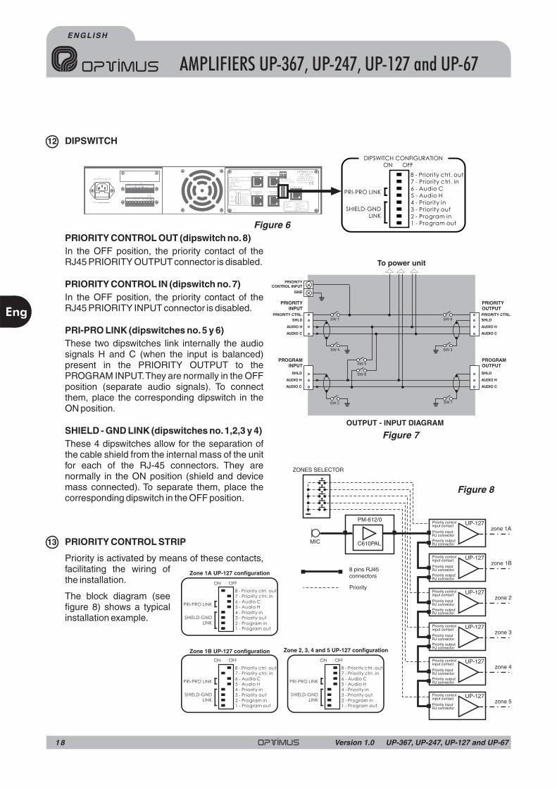
DIPSWITCH
PRIORITY CONTROL OUT (dipswitch no.8)
PRIORITY CONTROL IN (dipswitch no.7)
PRI-PRO LINK (dipswitches no.5 y 6)
SHIELD - GND LINK (dipswitches no.1,2,3 y 4)
PRIORITY CONTROL STRIP
In the OFF position, the priority contact of theRJ45 PRIORITY OUTPUT connector is disabled.
In the OFF position, the priority contact of theRJ45 PRIORITY INPUT connector is disabled.
These two dipswitches link internally the audiosignals H and C (when the input is balanced)present in the PRIORITY OUTPUT to thePROGRAM INPUT.They are normally in the OFFposition (separate audio signals). To connectthem, place the corresponding dipswitch in theON position.
These 4 dipswitches allow for the separation ofthe cable shield from the internal mass of the unitfor each of the RJ-45 connectors. They arenormally in the ON position (shield and devicemass connected). To separate them, place thecorresponding dipswitch in the OFF position.
Priority is activated by means of these contacts,facilitating the wiring ofthe installation.
The block diagram (seefigure 8) shows a typicalinstallation example.
12
13
OUTPUT - INPUT DIAGRAM
Figure 6
Figure 7
Figure 8
zone 1A
zone 1B
zone 2
zone 3
zone 4
zone 5
UP-127PM-612/0
MIC
ZONES SELECTOR
C610PAL
UP-127
UP-127
UP-127
UP-127
UP-127
Priority inputRJ connector
Priority inputRJ connector
Priority inputRJ connector
Priority inputRJ connector
Priority inputRJ connector
Priority inputRJ connector
Priority controlinput contact
Priority controlinput contact
Priority controlinput contact
Priority controlinput contact
Priority controlinput contact
Priority controlinput contact
Priority outputRJ connector
Priority outputRJ connector
Priority outputRJ connector
Priority outputRJ connector
Priority outputRJ connector
8 pins RJ45connectors
Priority
PRI-PRO LINK
SHIELD-GNDLINK
ON OFF
Zone 2, 3, 4 and 5 UP-127 configuration
PRI-PRO LINK
SHIELD-GNDLINK
ON OFF
Zone 1B configurationUP-127
PRI-PRO LINK
SHIELD-GNDLINK
ON OFF
Zone 1A configurationUP-127
To power unit
AUDIO H
PRIORITY CTRL.
PRIORITYCONTROL INPUT
GND
PRIORITYINPUT
PROGRAMINPUT
SHLD
SHLD
AUDIO H
SW 7 SW 8
SW 4 SW 3
SW 5
SW 2 SW 1
SW 6
AUDIO C
AUDIO C
PROGRAMOUTPUT
SHLD
AUDIO H
AUDIO C
AUDIO H
PRIORITY CTRL.
PRIORITYOUTPUT
SHLD
AUDIO C
Eng
AMPLIFIERS UP-367, UP-247, UP-127 and UP-67
ENGLISH
1 8 UP-367, UP-247, UP-127 and UP-67Version 1.0

SURVEILLANCE CONNECTOR
VENTILATION OUTPUT
Do not obstruct this output under anycircumstances.
UP-367 and UP-247
UP-127
It is used to link the amplifier with the speaker'sline surveillance card, where required.
For the connection use shielded RJ45connectors (see figure 9).
Equipped with one front and onerear fan. The front fan is activatedwhen the interior temperaturereaches 65ºC. The rear fan isact ivated when the inter iortemperature of the amplifierreaches 100ºC. This should onlyoccur in extreme conditions, since,with respect to its size, the unit hasbeen designed not to requireactivation of the rear fan.
If the internal temperature of theunit were to exceed 110ºC, theprotection device of the unit itselfwould be activated.
Equipped with a front fan. This isact ivated when the inter iortemperature reaches 100 ºC. Thisshould only occur in extremeconditions, since, with respect to itssize, the unit has been designed notto require the fan.
If the internal temperature of theunit were to exceed 110 ºC, theprotection device of the unit itselfwould be activated.
To replace the rear and/or front fanfollow the indications in figures 10and 11.
4. VENTILATION SYSTEM
14
GND
1
8
1
8
JP2(internal jumper)
15
Figure 10
Figure 9
Figure 11
Eng
19UP-367, UP-247, UP-127 and UP-67 Version 1.0
ENGLISH
AMPLIFIERS UP-367, UP-247, UP-127 and UP-67
Pin number 1: OSCILLATION INPUT
: OSCILLATION OUTPUT 1
: PROTECTION OUTPUT
: OSCILLATION OUTPUT 2
Pin number 6: PRIORITY OUTPUT
Pin number 7: +24VDC OUTPUT
8:
Shield
Pin number 3
Pin number 4
Pin number 5
Pin number
ONOFF
SURVEILLANCE RJ45
CONNECTION
7
8
65
2
3
1
1. OSCIN
2. NC3. OSCOUT 1
4. PROTECT
5. OSCOUT 2
6. PRI OUT7. +24VDC
OUTPUT
8.METALSHIELD
GND
DIPSWITCH
CONFIGURATION
ON
OFF
8. Priority ctrl. out
7. Priority ctrl. in
6. Audio C5. Audio H4. Priority In
3. Priority out
2. Programin
1. Programout
PRI-PROLINKSHIELD-GND
LINK
1. AUDIOSIGNAL H
2. AUDIOSIGNAL C
(WHEN
BALANCED)
3. +24 VDCOUTPUT
6. PRIORITY8.METALSHIELD
GND
PRIORITY &PROGRAM
RJ45 CONNECTION
SURVEILLANCE
PRIORITYINPUT
PRIORITYOUTPUT
PROGRAMINPUT
PROGRAMOUTPUT
PRIORITYCTRL. INPUT
GND
OPTIMUS S.A.
UP-247
POWER AM
PLIFIER
240WRM
S (312WIHF)
Engineering &Q.A.
FromEU (Spain)M
ade in China
UP
-24
7

0
50V
70V
100V
4Ω
8Ω
16Ω
SPEAKERSLINEOUTPUT
POWERSTAGE
PRIORITYCONTROL
INPUT
MASTERPRIORITY
MASTERPROGRAM
PRI-PROLINK
PROGRAM
PRIORITY
PROTECTION
PRIORITY OUTPUT
PRIORITY INPUT
PROGRAM OUTPUT
PROGRAM INPUT
SURETYPAGING
FAIL
SURVEILLANCE
Priority & Control Signal
Audio
5. BLOCK DIAGRAM
6. FACTORY SETUP CONFIGURATIONPriority contact from the RJ45 Priority Output connector: ON
Priority contact from the RJ45 Priority Input connector: ON
Priority and Program Audio link: OFF
Cable and RJ45 shield link to amplifier ground:ON
ON OFF
PRI-PRO LINKPRI-PRO LINK
SHIELD-GNDLINK
SHIELD-GNDLINK
7 - Priority ctrl. in7 - Priority ctrl. in8 - Priority ctrl. out8 - Priority ctrl. out
3 - Priority out3 - Priority out
DIPSWITCH CONFIGURATION
OTHER CONFIGURATIONJP1 (internal jumper) = OFF
JP2 (internal jumper) = ONSurveillance Shield - Ground Link
Eng
AMPLIFIERS UP-367, UP-247, UP-127 and UP-67
ENGLISH
2 0 UP-367, UP-247, UP-127 and UP-67Version 1.0
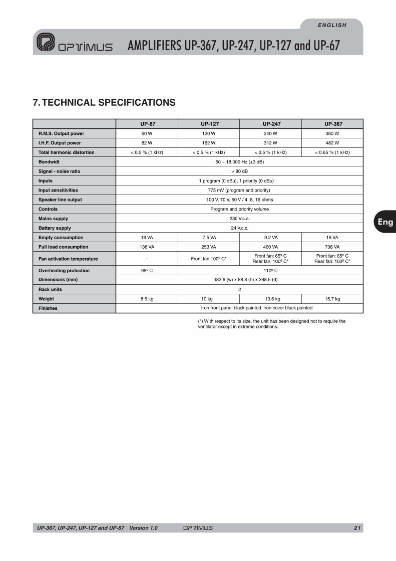
7.TECHNICAL SPECIFICATIONS
R.M.S. Output power
I.H.F. Output power
Total harmonic distortion
Bandwidt
Signal - noise ratio
Inputs
Input sensitivities
Speaker line output
Controls
Mains supply
Battery supply
Empty consumption
Full load consumption
Dimensions (mm)
Overheating protection
Fan activation temperature
Rack units
Weight
Finishes
120 W60 W
UP-127UP-67
240 W
UP-247
360 W
UP-367
< 0.5 % (1 kHz)< 0.5 % (1 kHz) < 0.5 % (1 kHz) < 0.65 % (1 kHz)
50 ~ 18.000 Hz (±3 dB)
1 program (0 dBu), 1 priority (0 dBu)
775 mV (program and priority)
100 V, 70 V, 50 V / 4, 8, 16 ohms
Program and priority volume
230 V.c.a.
7,5 VA16 VA 9.2 VA 16 VA
253 VA138 VA
-
460 VA 736 VA
482.6 (w) x 88.8 (h) x 368.5 (d)
Iron front panel black painted. Iron cover black painted
> 80 dB
24 V.c.c.
110º C95º C
Front fan:100º C*Front fan: 65º C
Rear fan: 100º C*Front fan: 65º C
Rear fan: 100º C*
2
10 kg8.6 kg 13.6 kg 15.7 kg
(*) With respect to its size, the unit has been designed not to require theventilator except in extreme conditions.
482 W162 W82 W 312 W
Eng
21UP-367, UP-247, UP-127 and UP-67 Version 1.0
ENGLISH
AMPLIFIERS UP-367, UP-247, UP-127 and UP-67

7. GUARANTEE1.GUARANTEE CERTIFICATE
1. OPTIMUS S.A. guarantees that its products are free from material andmanufacturing defects when they are first delivered to the purchaser.
2. In accordance with the conditions outlined here, OPTIMUS S.A. guaranteesits products for two (2) years from the date on which the purchaser acquires theproduct. If, within this guarantee period, defects appear which are not due tofactors outlined in section 2, OPTIMUS S.A. shall replace or repair the unitusing equivalent, new or reconstructed replacement parts, as it deems fit. Ifreplacement parts are applied which improve the unit, OPTIMUS S.A. reservesthe right to charge the client for the additional cost of these components.
3.No guarantee benefits shall be provided other than those cited here.
4. In order to claim the guarantee rights, it shall be an essential requirement topresent the original purchase invoice or the guarantee certificate.
2.GUARANTEE PROVISIONS
1. In the event that the product had to be modified or adapted to comply withlocal requirements concerning technical specifications or safety, and if thecountry in question is not the country for which the product was originallydesigned and manufactured, defects are not considered to be material ormanufacturing defects. Furthermore, the guarantee does not cover theexecution of these modifications or adaptations, regardless of whether or notthey have been carried out correctly.
Nor shall OPTIMUS S.A. be responsible for any costs under this guarantee forthese types of modifications.
2. The guarantee shall not entitle the purchaser to inspection or freemaintenance or repair of the unit, particularly if the defects are due toinappropriate use. Nor do the guarantee rights cover defects in wearing partsthat become worn as a result of normal wear and tear. Wearing parts are, inparticular, potentiometers, switches/keys, and similar parts.
3.The guarantee does not cover defects in the equipment unit caused by:
• Abuse or incorrect use of the unit for purposes other than those for which itis intended, in non-compliance with the service and maintenanceinstructions specified in the Manual and/or Technical Instructions for theunit.
• Connection or use of the product in a manner that does not correspond tothe technical or safety requirements of the country in which the unit is used.
• Installation in conditions other than those indicated in the Manual and/or
Technical Instructions.
• Deficiency or interruptions in the electricity supply or installation defectswhich imply use in abnormal conditions.
• Damage caused by other equipment units that are connected to theproduct.
• The use or installation of Software (programmes), interfaces, parts orsupplies not provided and/or not authorised by OPTIMUS S.A.
• Failure to use the original packaging for transportation.
• Damage caused by force majeure or other causes not attributable toOPTIMUS S.A.
4.The following elements are not covered by this guarantee:
• All plastic surfaces and all parts exposed to outdoor conditions which havebeen scratched or damaged as a result of normal or abnormal use.
• Breakages, knocks, damage due to a fall or scratches caused by movingthe unit in any way.
• Damage caused by tests, use, maintenance, installation or inappropriateadjustments, or as a result of any alteration or modification of any kind notcarried out by a Service Authorised by OPTIMUS S.A. in compliance withthis guarantee.
• Damage to persons or property that might be caused by the improper use ofthe equipment, including lack of maintenance.
5.The guarantee shall not be valid whenever the following is observed:
• Amendments or corrections made to the details of the guarantee certificateor purchase invoice.
• Failure to produce the original invoice or the absence of a date on this.
• Absence of the serial or batch number on the equipment.
6. In the case of personal computers, the guarantee will not cover theelimination of computer viruses, the restoration of programmes damaged bythese or the reinstallation of the disk following its deletion.
7.The rights of this guarantee are invalidated if the product has been repairedor opened by staff unauthorised by OPTIMUS S.A.or by the client himself.
8. If OPTIMUS S.A.were to establish before the client that the damage affectingthe unit does not entitle a claim to be made under the guarantee, the costs ofchecking the equipment incurred by OPTIMUS S.A.shall be borne by the client.
9. Products not covered by the guarantee shall only be repaired once paymenthas been effected by the client. In the event that the guarantee rights do notapply, OPTIMUS S.A. shall duly inform the client. If, within a period of 6 weeksfrom this communication, no written repair order is received from the clientconfirming acceptance of the costs, OPTIMUS S.A. shall return the unit inquestion to the client. In this case, the transport and packaging costs shall beinvoiced separately and payment shall be made on delivery. In the event that arepair order is sent by the client, confirming that he assumes the costs of repair,the transport and packaging costs shall be invoiced additionally, and alsoseparately.
10. If the equipment needs to be transferred to the Authorised Service Centre,transportation shall be effected by the responsible party according to theguarantee, who will also bear the freight and insurance costs.
11. In the event of a defect, OPTIMUS S.A. guarantees that the repair and/orreplacement of parts so that the unit operates correctly will be made within aperiod of no more than 30 days. Nevertheless, OPTIMUS S.A. would like toclarify that the normal period does not exceed 30 days.
12. All parts or products replaced as part of the guarantee services shallbecome the property of OPTIMUS S.A.
3.TRANSFER OF GUARANTEE
The guarantee is solely awarded to the original purchaser (principal client) andis not transferable. With the exception of OPTIMUS S.A., no third party(dealers, etc.) is authorised to award additional guarantees on behalf ofOPTIMUS S.A
4.CLAIMS FOR DAMAGE
In the event that OPTIMUS S.A. cannot provide a suitable guarantee service,the purchaser shall not be entitled to claim any indemnity for damages arising.The responsibility held by OPTIMUS S.A. is limited in all cases to the invoicingprice of the product.
5.RELATIONWITH OTHER GUARANTEE RIGHTS AND NATIONAL LAW
1.This guarantee does not affect the rights of the purchaser with respect to thevendor arising from the contract of sale accomplished.
2. These conditions of the guarantee provided by OPTIMUS S.A. are valid aslong as they do not contradict the corresponding national law on guaranteeprovisions.
3. OPTIMUS S.A. guarantees that this product complies with the safetyregulations in force in the country.
THIS LIMITED GUARANTEE DECLARATION IS THE EXCLUSIVEGUARANTEE OFFERED BY OPTIMUS S.A. ALL OTHER EXPLICIT ORIMPLICIT GUARANTEES ARE EXCLUDED, AND THIS ALSO APPLIES TOGUARANTEES OF MARKETABILITY AND SUITABILITY FOR APARTICULAR PURPOSE. (EXCEPT WHEN THESE GUARANTEES AREREQUIRED BY AN APPLICABLE LAW). NO GUARANTEE, EITHEREXPLICIT OR IMPLICIT, SHALL BE APPLIED ONCE THE GUARANTEEPERIOD HAS EXPIRED.
OPTIMUS S.A.After-Sales ServiceC/ Barcelona 10117003 - GIRONATel.902 151 96 / 972 203 300Fax.972 21 84 13e-mail :[email protected] 1999/44/CE
AMPLIFIERS UP-367, UP-247, UP-127 and UP-67
Eng
ENGLISH
2 2 UP-367, UP-247, UP-127 and UP-67Version 1.0

CENTRAL:
DELEGACIONES:
REPRESENTANTES:
E-17003 GIRONA (SPAIN)Barcelona, 101Tel. 972 203 300Fax 972 218 413E-mail: [email protected]
www.optimus.es
06010 BADAJOZCipriano J.S. del AmoJacobo Rodriguez Pereira,11Tel. 924 207 483Fax 924 200 115E-mail: [email protected]
BARCELONAAvda.Roma, 84Tel. 932 262 501Fax 932 265 209E-mail: [email protected]
SALAMANCAManuel MartínTel./Fax 923 185 149E-mail: [email protected]
Atención al ClienteTel. 902 151 963
E-28019 MADRIDAntonio López, 56Tel. 902 117 168Tel. 914 609 860Fax 914 604 008E-mail: [email protected]
Gestión de ProyectosTel. 972 222 109Fax 972 221 767E-mail: [email protected]
ZARAGOZATel/Fax 976 694 933Tel. 659 068 799 móvilE-mail:[email protected]. 902 117 187
Export DepartmentTel. +34 972 203 300Fax +34 972 218 413E-mail: [email protected]
E-48006 BILBOZumalakárregui, 48Tel. 944 598 116
122 775Fax 944 730 596E-mail: [email protected]
Tel. 944
E-46015 VALENCIAAv. Maestro Rodrigo, 101Tel. 963 461 039Fax 963 461 038E-mail: [email protected]
E-41007 SEVILLARuiz de Alarcón, 25Tel. 954 578 280Fax 954 572 188E-mail: [email protected]
E-15006 A CORUÑANovoa Santos, 27Tel. 981 298 400Fax 981 298 506E-mail: [email protected]
E-29004 MALAGADiderot, 9 Bq. F Nv. 47APlg. Ind. GuadalorceTel. 952 232 947Fax 952 236 578Email: [email protected]
E-30009 MURCIASierra Peñarrubia, 1Esq. c/ MaravillasTel. 968 284 748Fax 968 282 637Email: [email protected]
E-07009 PALMA de MALLORCAGremi Teixidors, 35 1º Izq.Plg. Ind. Son CastellóTel. 971 433 561Fax 971 430 298E-mail: [email protected]
VIGONicolás Onaindia VelascoTel. 981 298 400Tel. 981 298 400E-mail: [email protected]
GIJON (Asturias)Tel./ Fax 985 130 343Tel. 659 583 506 móvilE-mail: [email protected]