upc 1997 w 1999 ind amendments
TRANSCRIPT

UNIFORM PLUMBING CODETM
1997 EDITION
Adoptedat the Sixty-Seventh Annual Conference September, 1996
~NTERNAT~ONAL ASSOCIATION OF PLUMBING AND MECHANICAL OFFICIALS
A Nonprofit Association

Indiana Amendments Symbols
Symbols in the margins indicate the status of code changes:
11 This symbol indicates an amendment by the State of lndiana to the Uniform Plumbing Code.
> This symbol indicates a deletion by the State of lndiana from the Uniform Plumbing Code.
I This symbol indicates an amendment by the lnternational Association of Plumbing and Mechanical Officials to the Uniform Plumbing Code.
4 This symbol indicates a deletion by the lnternational Association of Plumbing and Mechanical Officials from the Uniform Plumbing Code.
Copyright Q 2000 by -
INTERNATIONAL ASSOCIATION OF PLUMBING AND MECHANICAL OFFICIALS All Rights Resewed
No part of this work may be reproduced or recorded in any form or by any means, except as may be expressly permitted in writing by the publisher.
First Printing, February 2000 Second Printing, July 2000
Published by the International Association of Plumbing and Mechanical Officials 20001 Walnut Drive South, Walnut, CA, 91789-2825

FOREWORD
The advantages of a uniform plumbing code adopted by various local jurisdictions have long been recognized. Disorder in the industry as a result of widely divergent plumbing practices and the use of many different, often conflicting, plumbing codes by local jurisdictions influenced the Western Plumbing Officials Association (now the International Association of Plumbing and Mechanical Officials [IAPMO]) to form a committee of plumbing inspectors, master and journeyman plumbers, sanitary and mechanical engineers, assisted by public utility companies, and the plumbing industry to create a basic plumbing document for general use. The product of this effort, the first edition of the Uniform Plumbing CodeTM (UPCTM) was officially adopted by IAPMO in 1945. The widespread use of this code over the past five decades by jurisdictions throughout the United States is testimony to its merit.
With the publication of this 1997 edition of the UPC, a significant milestone has been reached. For the first time in history, a plumbing code has been created which is the result of a collaboration of industry-wide entities. The National Association of Plumbing-Heating-Cooling Contractors (NAPHCC) and the Mechanical Contractors Association of America (MCAA) joined forces with IAPMO to create this amalgamation of the most desirable aspects of the three most respected plumbing codes in existence. The 1994 Uniform Plumbing Code published by IAPMO, the 1993 ANSI A40 Safety Requirements for PlumbingTM published by the MCAA and NAPHCC Joint Task Force, and the National Standard Plumbing CodeTM published by NAPHCC were scrupulously dissected and reassembled into this, the finest plumbing code document ever published.
The memberships of the three aforementioned associations are composed of representatives of all facets of the plumbing industry. They include plumbing contractors, installers, inspectors, building officials, engineers, architects, designers, manufacturers, wholesalers and consumers.
The UPC is designed to provide consumers with safe and sanitary plumbing systems, while, at the same time, allowing latitude for innovation and new technologies. The users of the UPC are continuously encouraged to update and to submit changes to improve the code. Amendments adopted by the IAPMO membership are incorporated into the code, which is published every three years. it is this
process that keeps the code current with the latest technological advances in the industry.
The 1997 edition of the UPC is organized in the "common code format." This format standardizes the organization of the major model plumbing codes throughout the United States, so that topics are arranged in the same order in all of the plumbing codes. For example, information on plumbing vents is found in Chapter 9 in each of the plumbing codes. This new format is intended to be more "user friendly" for designers, inspectors, plumbers and manufacturers working with several codes at the local, national and international levels.
The Uniform Plumbing Code is dedicated to all those who, in working to achieve "the ultimate plumbing code," have unselfishly devoted their time. effort, and personal funds to create and maintain this, the finest plumbing code in existence.
The 1997 Uniform Plumbing Code is sponsored by NAPHCC and MCAA. The presence of the logos of NAPHCC and MCAA, while reflecting support. does not imply any ownership of the copyright to the UPC which is held exclusively by IAPMO. NAPHCC may be contacted at P.O. Box 6808, Falls Church, Virginia 22046, 800-533-7694. MCAA may be contacted at 1385 Piccard Drive, Rockville, Maryland 20850, 301 -869-5800.

TABLE OF CONTENTS ... Foreword .......................................................................................................................................................... III
Related Publications and Services .................................................................................................................... v
Membership in IAPMO .................................................................................................................................... vii
Organization of IAPMO .................................................................................................................................... vii
UPC Code Change Cycle .............................................................................................................................. vii
How to Contact IAPMO ................................................................................................................................. vii ... Sample Ordinance for Adopting the 1997 UPC ................... .. ................
Indiana Preface ............................................................................................................................................... ix
Chapter 1 -- Administration ............................................................................................................... 1 . .
Chapter 2 -- Defin~t~ons ........................................................................................................................... 3
Chapter 3 -- General Regulations ............................................................................................................ 11
Chapter 4 -- Plumbing Fixtures and Fixture Fittings ................................................................................ 17
Chapter 5 -- Water Heaters ....................................................................................................................... 23
Chapter 6 -- Water Supply and Distribution ............................................................................................. 25
Chapter 7 -- Sanitary Drainage .............................................................................................................. 39
Chapter 8 -- Indirect Wastes ..................................................................................................................... 71
Chapter 9 -- Vents ..................................................................................................................................... 75
Chapter 10 -- Traps and Interceptors .......................................................................................................... 79
Chapter 11 --. Storm Drainage ................................................................................................................... 85 ( ( > Chapter 12 -- Fuel Piping (Deleted) .......................................................................................................... 97
> Chapter 13 -- Medical Gas Systems (Deleted) ....................................................................................... 119
Chapter 14 -- Mandatory Referenced Standards .................................................................................. 129
> Appendix A --. Recommended Rules for Sizing the Water Supply System (Deleted) .............................. 117
> Appendix B -- Explanatory Notes on Combination Waste and Vent Systems (Deleted) ......................... 119
> Appendix C --- Additional Referenced Standards (Deleted) ...................................................................... 121
Appendix D -- Sizing Stormwater Drainage Systems ................................................................................. 123
> Appendix E --. ManufacturedfMobile Home Parks and Recreational Vehicle Parks (Deleted) .................. 131
Appendix F . Reserved
> Appendix G- Graywater Systems for Single Family Dwellings (Deleted) ........................................... 133
> Appendix H . Recommended Procedures for Design . Construction and Installation of
Commercial Kitchen Grease Interceptors (Deleted) ...................................................... 135
> Appendix I -- Installation Standards (Deleted) ...................................................................................... 137
> Appendix J -- Reclaimed Water Systems for Non-Residential Buildings (Deleted) ................................. 139
> Appendix K -- Private Sewage Disposal Systems (Deleted) .................................................................... 141
> Appendix L -- Alternate Plumbing Systems (Deleted) ............................................................................. 143 Rule 2 -- American Society of Sanitary Engineers Standard 1051-1998 ........................................... 145
Useful Tables ............................................................................................................................................. 147
Index ............................................................................................................................................. 155

RELATED PUBLlCATlONS AND SERVICES IAPMO provides a variety of other products which are useful for inspectors, building officials, architects, engineers, manufacturers, contractors, plumbers, and apprentices.
IAPMO ORDER DESK 20001 WALNUT DRIVE SOUTH
WALNUT, CA 91789-2825 PHONE: 909-595-&149, EXT. 113, FAX: 909-594-3690
FOR PUBLICATIONS ORDERS: 800-85-IAPMO
Uniform Plumbing Code - Spanish Edition: This UPC will assist the Spanish-speaking community in its utilization of the most widely adopted plumbing code in the world. The UPC was translated in response to numerous requests from jurisdictions throughout the US with large Spanish-speaking populations.
Uniform Plumbing Code on CD Rom: With this CD, the Code is fully indexed and searchable, making it easy to get to the critical information you need without leafing through bulky books or dealing with torn pages.
Uniform Plumbing Code Interpretations Manual: This increasingly popular manual is the result of ongoing work by IAPMO's Code Interpretations Committee. Updated annually, it contains hundreds of questions and answers. Many of these questions arise in the daily administration and enforcement of the code. lnterpretation requests are accepted from active IAPMO members. lnterpretation Request Forms are available in Official magazine or from IAPMO.
Uniform Plumbing Code tilustrated Training Manual: The UPC Illustrated Training Manual is an excellent reference for anyone involved in the plumbing industry. It has an extensive definitions section and several hundred comprehensive technical diagrams and illustrations. It serves as a textbook, and it also is useful as a valuable tool for explaining the intent and use of the Code.
Uniform Plumbing Code Study Guide: This book is the perfect complement to the UPC Illustrated Training Manual. Alone, it constitutes a complete chapter-by-chapter self-study course for learning the UPC. It has hundreds of questions, general practice exams, a section on plumbing math, numerous pipe sizing exercises, and a section on fitting identilication. The questions and answers in the UPC Study Guide are kept current by IAPMO's Education Committee.
Dwelling Requirements of the Uniform Plumbing Code: This books contains the UPC requirements which apply to one and two family dwellings only. Its illustrations and photographs make it especially useful for combination dwelling inspectors and the do-it-yourselfer.
Cumulative Analysis of Uniform Plumbing Code Changes: An excellent reference for learning and understanding plumbing code changes adopted at the Annual Education and Business Conferences. It is also useful for parties preparing proposed code changes.
Uniform Mechanical Code The Uniform Mechanical Code contains complete requirements for the installation and maintenance of heating, ventilating, cooling, and refrigeration systems.
Uniform Mechanical Code Study Guide: Similar in design to the Uniform Plumbing Code Study Guide, the Uniform Mechanical Code Study Guide covers all aspects of the UMC in detail.
Handbook to the Uniform Mechanical Code An indispensable tool for understanding the provisions of the Uniform Mechanical Code

Uniform Solar Energy Code: Provides a complete set of regulations for the use of solar energy in both plumbing and mechanical systems.
Uniform Swimming Pool, Spa, and HOP Tub Code: Contains complete and current guidelines for piping systems sewing these increasingly popular amenities.
IAPMO Installation Standards: IAPMO standards committees have formulated installation standards for a wide variety of commonly used plumbing materials and systems. The IAPMO installation standards are included afler the text of the Uniform Plumbing Code. Separate printed copies are also available.
Material and Property Standards: Although IAPMO does not generally develop material and property standards, when it becomes apparent that necessary standards are nonexistent, iAPMO has exercised leadership by developing them. IAPMO's standards are always subject to modifications and improvements, and are withdrawn when acceptable nationally-recognized consensus standards are formulated.
Manufactured Home and Recreational Vehicle Standards: Similar to the material and property standards, IAPMO has developed a number of standards for specialty products used in manufactured homes and recreational vehicles. These standards are available individually, or they may be purchased as a set.
ANSI Z 124 Standards: These standards are written to specifically address a variety of plastic plumbing fixtures and components. They are available individually, or may be grouped for quantity discounts.
Directory of Llsted Plumbing Products: The IAPMO R&T Listing Program was primarily created to benefit the building and plumbing officials in the growing number of jurisdictions that adopt and use the UPC. For a product to be listed by IAPMO R&T, it must be found to be in conformance with an accepted standard or criteria and must not be in conflict with the UPC. IAPMO R&T administers a listing compiiance program with unannounced inspections of manufacturing facilities, conducted to verify compliance with listing requirements.
This directory contains information on several thousand IAPMO R&T listed plumbing products and is updated monthly.
Directory of Listed Plumbing Products for Manufactured Housing and Recreational Vehicles: This directory contains information on several hundred IAPMO R&T listed plumbing products used in manufactured housing and recreational vehicies and is updated bi-monthly.
Official Magazine: IAPMO's bimonthly publication features informative articles on plumbing, locai chapter proceedings and events, and plumbing industry updates. All IAPMO members receive a free subscription.
Drain Waste and Vent Calculator: This calculator provides quick and simple access to the fixture unit and sizing tables of Chapter 7 of the UPC.
Water Sizing Calculator: Sizing water systems becomes a much simpler task with the use of this handy calculator.
Natural Gas Pipe Sizing Calculator: Designed for systems with a supply pressure of six to eight inches of water column, all pipe capacities are given in cubic feet per hour.

MEMBERSHIP IN lAPMO IAPMO is an open association. ~embersh i~ categories have annual dues from $10.00 to $300.00. Member benefits include discounted prices on most IAPMO publications, a subscription to Official magazine, and the opportunity to participate in updating and improving the most comprehensive plumbing code available.
Some membership categories include additional benefits. For additional information, contact IAPMO's Membership Department.
ORGANIZATION OF IAPMO IAPMO is a nonprofit association governed by a Board of Directors, consisting of a President, Vice President, Immediate Past President, and nine Directors. The Board of Directors is elected by the active members at the Annual Education and Business Conference. The President and Vice President serve one year terms. The Directors serve for three years. A Secretary and Treasurer are appointed annually from the active membership by the Board of Directors.
The daily business of the association is conducted by IAPMO's staff, in coordination with IAPMO's standing and ad hoc committees.
UPC CODE CHANGE CYCLE For the first time in IAPMO's long history, the 2003 edition of the Uniform Plumbing Code (UPC) will be developed utilizing a consensus process. The UPC will be harmonized with the Uniform Mechanical Code (UMC) and with the National Fire Protection Associations' National Electrical Code. Life Safety Code and Fire Code.
HOW TO CONTACT IIAPMO Mailing Address: Phone Numbers: Office Hours: 20001 Walnut Drive South 909-595-8449 Monday through Friday Walnut, CA 91789-2825 Fax: 909-594-3690 8:00 am to 5:00 pm Pacific time
Publications orders: Closed weekends and holidays Internet information: 1-800-85-IAPMO
Web Site: http://www.iapmo.org E-Mail Address: [email protected]

Sample Ordinance for Adoption of the 1997 Uniform Plumbing Code
Ordinance No. -
An ordinance of the fiurisdiction) adopting the 1997 edition of the "Uniform Plumbing Code", including IAPMO Installations Standards contained in Appendix I, regulating and controlling the design, construction, quality of materials, erection, installation, alteration, repair, location, relocation, replacement, addition to, use or maintenance of any plumbing system in the liurisdiction) ; providing for the issuance of permits and collection of fees therefore; repealing Ordinance No. - of the fiurisdiction) and all other ordinances and parts of the ordinances in conflict therewith.
The faovernina bodvl of the (iurisdiction) does ordain as follows:
Section 1. That certain documents, three (3) copies of which are on file in the office of the fiurisdiction's keeoer of records) and the (iurisdiction) . being marked and designated as "Uniform Plumbing Code", (including Appendix chapters - (fill in the applicable Appendix chapters) be and are hereby adopted as the code of the fiurisdiction) for regulating the design, construction, quality of materials, erection, installation, alteration, repair, location, relocation, replacement, addition to, use or maintenance of plumbing systems in the Ourisdiction) providing for the issuance of permits and collection of fees therefore; and each and all of the regulations, provisions, conditions and terms of such "Uniform Plumbing Code", 1997 edition, and Appendix I published by the International Association of Plumbing and Mechanical Officials, on file in the office of the fiurisdiction) are hereby referred to, adopted and made a pan hereof as if fully set out in this ordinance.
Section 2. (Incorporate penalties for violations. See Section 102.3.2.)
Section 3. That Ordinance No. -of fiurisdiction) entitled (fill in here the complete title of the present plumbing ordinance or ordinances in effect at the present time so that they will be repealed by definite mention) and all other ordinances or parts of ordinances in conflict herewith are hereby repealed.
Section 4. That it any section, subsection, sentence, clause or phrase of this ordinance is, for any reason, held ! : i / to be unconstitutional, such decision shall not affect the vaiidity of the remaining portions of this ordinance. The (aovernina bodv) hereby declares that it would have passed this ordinance, each section, subsection, clause or phrase thereof, irrespective of the fact that any one or more sections, subsections, sentences, clauses and phrases be declared unconstitutional.
Section 5. That the fiurisdiction's kee~er of records) is hereby ordered and directed to cause this ordinance to be published. (An additional provision may be required to direct the number of times the ordinance is to be published and to specify that it is to be in a newspaper in general circulation. Posting may also be required.)
Section 6. That this ordinance and the rules, regulations, provisions, requirements, orders and matters established and adopted hereby shall take effect and be in full force and effect (time oeriod) from and after the date of its final passage and adoption.

INDIANA PLUMBING CODE
PREFACE
'The provisions in this plumbing code that regulate sewer and water distribution systems from the build- ing foundation wall to the property line do not, in any wax determine whether licensure is required or not required of those performing the work, nor do they detemline jurisdictional requirements. The plumbing licensure requirements in statute for the State of Indiana remain the same as they have been, and are found in statute at IC 25-28.5, including the excep- tions at IC 25-28.5-1-32(9) as follows:
This chapter does not apply to the following: (9) A sewer contractor, sewage disposal contrac- tor, or an excavation contractor or utility contrac- tor who generally engages in the business of installing, altering, or repairing sewers, private or public sewage disposal systems, and water dis- tribution or drainage lines outside ihe foundation walls of a building
Also, the plumbing licensure exceptions in the Plumbing Commission's rule, which establishes stan- dards for the competent practice of plumbing, are set forth at 860 IAC 1-5-5(b) as follows:
(b) Subsection (a) shall not be construed to require the following individuals to be licensed:
(1) helpers; (2) laborers; (3) registered apprentices; and (4) other employees of a plumbing contractor or journeyman plumber: who do not in any manner hold themselves out to the public as being plumbers.
'Asterisks appearing in the plumbing code amend- ments that follow, indicate parts of the plumbing code that might cause confusion regarding the licensure issue.
Rule 1.3. Indiana Plumbing Code, 1999 Edition 675 IAC 16-1.3-1 Title; availability
Sec. 1. (a) This rule shall be known as the lndiana Plumbing Code, 1999 Edition, and shall be published, except for incorporated documents, by the fire and building services department, for general distribution and use under that title. Wherever the term "this code" is used within this rule, it shall mean the lndiana Plumbing Code, 1999 Edition.
(b) The lndiana Plumbing Code, 1999 Edition, is available for purchase from the Fire and Building Services Department, lndiana Government Center-South, 402 West Washington Street, Room W221, Indianapolis, lndiana 46204- 2739.
675 IAC 16-1.3-2 Adoption by reference
Sec. 2 That certain document, being titled as the Uniform Plumbing Code, 1997Edition, pub- lished by the International Association of Plumbing and Mechanical Officials, 20001 Walnut Drive, Walnut, California 91789-2825, be and the same k hereby adopted by reference, as if fully set out in this rule, save and except those arnend- ments made in this rule.

UNIFORM PLUMBING CODE

CHAPTER 1
ADMINISTRATION
101.0 Scope, Intent 101.1 Scope. The provisions of this code shall apply to the construction, alteration, and addition to plumbing equipment and systems regulated by this code for Class 1 structures except townhouses. Compliance with this code for Class 2 structures or Class 1 townhouses is evidence of compliance with 675 IAC 14, the Indiana One and Two Family Dwelling Code.
Provisions in the appendices are not enforceable unless specifically adopted. 101.2 intent. The purpose of this code is to provide minimum standards for safety and to safeguard, property and public welfare by regulating and controlling the design, construction, installation, quality of material and location of plumbing equipment and systems.
102.0 Plans. Plans shall be submitted for Class 1 structures as required by the General Administrative Rules (675 IAC 12-6), and for Class 2 structures as required by local ordmance.
103.0 Existing Construction. For existing construction see the General Administrative Rules (675 IAC 12-4) and local ordinance.
Maintenance of plumbing systems shall be in conformance with the General Administrative Rules ( G A R ) of the Fire Prevention and Building Safety Commission as set forth at 675 IAC 22-4-9, as follows: Excerptfrom the General Administrative Rules. 675 IAC 12-4-9 Maintenance of Bui ldings and Structures
Sec. 9. (a) A11 buildings and structures, and any part of the permanent heating, ventilating, air conditioning, electrical, plumbing, sanitary, emergency detection, emergency communication, orfire or explosion systems, and all parts thereof, shall be maintained in conformance with the applicable rules of the Commission, or applicable rules of i ts predecessor agencies, in effect when constructed, installed, or altered.
(b) The requirements of subsection (a) shall not prohibit maintenance in conformance with the current applicable building rules of the Commission or in another manner which would be at least as safe, sanitary, energy conserving and accessible to persons with a physical disability as that required by subsection (a).
fc) Buildings and structures, and any part of the permanent heating, ventilating, air conditioning, electrical, plumbing, sanitary, emergency detection, emergency communication, or fire or explosion suppression systems, and all parts thereof, constructed, installed or altered prior to the adoption of applicable rules of the Commission or its predecessor agencies (including construction, installation or alteration prior to the creation of the predecessor agencies) shall be maintained in a condition at least as safe and sanitary as they were when constructed, installed or altered.
(d ) This section does not prohibit the removal of buildings, structures, or any part of the permanent heating, ventilating, air conditioning, electrical, plumbing, sanitary, emergency detection, emergency communication, orfire or explosion suppression systems, or components thereof not required for the current use and occupancy by the rules of the Commission or i ts predecessor agencies at the time of construction, installation or alteration (including construction, installation or alteration prior to the creation of the predecessor agencies).
(e) Notwithstanding subsection (d), no alteration or removal shall cause an existing building, structure, or any part of the permanent heating, ventilating, air conditioning, electrical, plumbing, sanitary, emergency detection, emergency communication, or fire or explosion suppression systems to become unsafe or overloaded under the provisions of the current rules of the Commission for new construction.
(f) Notwithstanding subsection (d), no alteration or removal shall reducefire protection or detection systems or exit capacities to a level less than that required under the provisions of the current rules of the Commission for new construction.
104.0 Conflicts between Codes. For conflicting requirements within the Fire Prevention and Building Safety Commission's rules see the General Administrative Rules (675 IAC 12-4). 105.0 Additions and Alterations. Additions or Alterations to any plumbing system shall conform to that required for a new plumbing system without requiring the existing plumbing system to comply with all the requirements of this code. Additions or alterations shall not cause an existing system to become unsafe, insanitary, or overloaded.
Minor additions or alterations to existing plumbing systems shall be permitted in the same

UNIFORM PLUMBING CODE
manner and arrangement as in the existing system, provided that such additions or alterations are not hazardous and are approved.
106.0 Department of Plumbing Inspections, Permits end inspections. The department of plumbing inspections, and permitting is created and regulated by local ordinance.
107.0 Appeals. Appeals from orders issued by the Fire Prevention and Building Safety Commission or the State Building Commissioner are governed by IC 4-21.5 and IC 22-12-7. Appeals from orders issued by a local unit of government are governed by 1C 22-13- 2-7 and local ordinance.

CHAPTER 2
DEFINITIONS
201.0 General For the purpose of this Code, the following terms have the meanings indicated in this chapter.
No attempt is made to define ordinary words which are used in accordance with their established dictionary meanings, except where a word has been used loosely and it is necessary to define its meaning as used in this Code to avoid misunderstanding.
The definitions of terms are arranged alphabetically according to the first word of the term.
202.0 Definition of Terms
203.0 - A -
ABS - Acrylonitrile-Butadiene-Styrene. Accessible - When applied to a fixture, connection, appliance, or equipment, "accessible" means having access thereto, but which first may require the removal of an access panel, door, or similar obstruction. "Readily accessible" means direct access without the necessity of removing any panel, door, or similar obstruction. Administrative Authority - means the State Building Commissioner or officer of a local unit of government empowered by law to administer and enforce the rules of the Fire Prevention and Building Safety Commission. For purposes of industrialized building systems (675 IAC 15), Administrative Authority means the State Building Commissioner. Airbreak - A physical separation which may be a low inlet into the indirect waste receptor from the fixture, appliance, or device indirectly connected. Air Chamber - A pressure surge-absorbing device operating through the compressibility of air. Airgap, Drainage - The unobstructed vertical distance through the free atmosphere between the lowest opening from any pipe, plumbing fixture, appliance or appurtenance conveying waste to the flood level rim of the receptor. Airgap, Water Distribution - The unobstructed vertical distance through the free atmosphere between the lowest opening from any pipe or faucet conveying potable water to the flood level rim of any tank, vat or fixture. Anchors - See Supports.
II Approved - means, as to materials, equipment, products, and construction, acceptance by the
administrative authority by one (1) of the following methods: investigation or tests conducted by recognized authorities; or investigation or tests conducted by technical or scientific organizations; or accepted principles. The investigation, tests, or principles shall establish that the materials, equipment, products, and construction are safe for their intended purposes. Approved Testing Agency - means an established and recognized agency regularly engaged in conducting tests or furnishing inspection services, when such agency has been approved. Area Drain - A receptacle designed to collect surface or storm water from an open area. Aspirator - A fitting or device supplied with water or other fluid under positive pressure which passes through an integral orifice or constriction, causing a vacuum.
204.0 - B - Backflow - The flow of water or other liquids, mixtures, or substances into the distributing pipes of a potable supply of water from any sources other than its intended source. See Back-Siphonage, Back- Pressure Backflow. Backflow Connection - Any arrangement whereby backflow can occur. Back-Pressure Backflow - Backflow due to an increased pressure above the supply pressure, which may be due to pumps, boilers, gravity or other sources of pressure. Backflow Preventer - A device or means to prevent backflow into the potable water system. Back-Siphonage -The flowing back of used, contaminated, or polluted water from a plumbing fixture or vessel into a water supply pipe due to a negative pressure in such pipe. See Backflow. Backwater Valve - A device installed in a drainage system to prevent reverse flow. Bathroom - A room equipped with a shower or bathtub. Battery of Fixtures - Any group of two (2) or more similar, adjacent fixtures which discharge into a common horizontal waste or soil branch. Boiler Blowoff - An outlet on a boiler to permit emptying or discharge of sediment. Branch -Any part of the piping system other than a main, riser, or stack.

UNIFORM PLUMBING CODE
Branch, Fixture - See Fixture Branch. Branch, Horizontal -See Horizontal Branch. Branch Vent - A vent connecting one or more individual vents with a vent stack or stack vent. Brazed Joint - Any joint obtained by joining of metal parts with alloys which melt at temperatures higher than 840°F (44g°C), but lower than the melting temperature of the parts to be joined. Building - means any structure occupied or intended to support or shelter any occupancy. Building Code - means the Indiana Building Code for Class 1 structures except for townhouses, or the Indiana One and Two Family Dwelling Code for Class 2 structures and Class 1 townhouses in effect at the time of construction, addition, or alteration of the plumbing system. "Building Drain - That part of the lowest piping of a drainage system which receives the discharge from soil, waste, and other drainage pipes inside the walls of the building and conveys it to the building sewer beginning two (2) feet (610 mm) outside the building wall. Building Drain (Sanitary) - A building drain which conveys sewage only. Building Drain (Storm) - A building drain which conveys storm water or other drainage, but no sewage.
11 *Building Sewer - That part of the horizontal piping of a drainage system which extends from the end of the building drain and which receives the discharge of the building drain and conveys it to a public sewer, private sewer, individual sewage disposal system, or other point of disposal. Building Sewer (Combined) - A building sewer which conveys both sewage and storm water or other drainage. Building Sewer (Sanitary) - A building sewer which conveys sewage only. Building Sewer (Storm) - A building sewer which conveys storm water or other drainage, but no sewage. Building Subdrain - That portion of a drainage system which does not drain by gravity into the building sewer. Building Supply - The pipe carrying potable water from the water meter or other source of water supply to a building or other point of w or distribution on the lot. Building supply shall also mean water sewice.
205.0 - C - > Certified Backflow Assembly Tester - DELETED
Cesspool - A lined excavation in the ground which
receives the discharge of a drainage system or part l I' thereof, so designed as to retain the organic matter ( a,
and solids discharging therein, but permitting the liquids to seep through the bottom and sides. Chemical Waste - See Special Wastes. Circuit Vent - A vent that connects to a horizontal drainage branch and vents two (2) traps to a maximum of eight (8) traps or trapped fixtures connected into a battery. Clarifier -See Interceptor. Clear Water Waste - Cooling water and condensate drainage from refrigeration and air-conditioning equipment; cooled condensate from steam heating systems; cooled boiler blowdown water. Clinic Sink - A sink designed primarily to receive wastes from bedpans and having aflush rim, an integral trap with a visible trap seal, and the same flushing and cleansing characteristics as a water closet. Code - DELETED < Combination ThermostaticIPressure Balancing Valve - A mixing valve which senses outlet temperature and incoming hot and cold water pressure and compensates for fluctuations in incoming hot and cold water temperatures and pressures to stabilize outlet temperatures. Combination Waste and Vent System - A specially designed system of waste piping embodying the I' (x
horizontal wet venting of one or more sinks or floor drains by means of a common waste and vent pipe, adequately sized to provide free movement of air above the flow line of the drain. *Combined Building Sewer - See Building Sewer, 11 (Combined). Combustible Construction - See the Building Code. Common -That part of a plumbing system which is
I1 so designed and installed as to serve more than one (1) appliance, fixture, building, or system. Conductor - A pipe inside the building which conveys storm water from the roof to a storm drain, combined building sewer, or other approved point of disposal. See Downspout. Confined Space - DELETED < Contamlnation - An impairment of the quality of the potable water which creates an actual hazard to the public health through poisoning or through the spread of disease by sewage, industrial fluids or waste. Also defined as High Hazard. Continuous Vent - DELETED < Continuous Waste - A drain connecting the compartments of a set of fixtures to a trap or ((: connecting other permitted fixtures to a common trap.

DEFINITIONS 205.0 - 209.0
Critical Level - The critical level (C-L or C/L) marking on a backflow prevention device or vacuum breaker is a point conforming to approved standards and established by the testing laboratory (usually stamped on the device by the manufacturer) which determines the minimum elevation above the flood level rim of the fixture or receptacle served at which the device may be installed. When a backflow prevention device does not bear a critical level marking, the bottom of the vacuum breaker, combination valve, or the bottom of any such approved device shall constitute the critical level.
Cross-Connection - Any connection or arrangement, physical or otherwise, between a potable water supply system and any plumbing fixture or any tank, receptacle, equipment or device, through which it may be possible for non-potable, used, unclean, polluted and contaminated water, or other substances, to enter into any part of such potable water system under any condition.
206.0 - D - Dead End - A branch leading from a soil, waste or vent pipe, building drain, o; building sewer, and terminating at a developed length of two (2) feet (610 mm) or more by means of a plug, cap, or other closed fitting, except for piping serving as a cleanout extension to an accessible area.
II Department Having Jurisdiction - See AdministrativeAuthority.
Developed Length - The length along the center line of a pipe and fittings.
Diameter - Unless specifically stated, "diameter" is the nominal diameter as designated commercially.
II Domestic Sewage - means the liquid and water- borne wastes derived from the ordinary living processes, free from industrial wastes. Downspout - The rainleader from the roof to the building storm drain, combined building sewer, or other means of disposal located outside of the building. See Conductor and Leader. Drain -Any pipe which carries waste or water-borne ,. . wastes in a building drainage system.
*Drainage System - Includes all the piping within public or private premises, which conveys sewage or other liquid wastes to a legal point of disposal, but does not include the mains of a public sewer system or a public sewage treatment or disposal plant. Durham System - A soil or waste system in which all piping is threaded pipe, tubing, or other such rigid construction, using recessed drainage fittings to correspond to the types of piping.
Effective Opening - The minimum cross-sectional area at the point of water supply discharge measured or expressed in terms of: (1) diameter of a circle, or (2) if the opening is not circular, or the diameter of a circle of equivalent cross-sectional area. (This is applicable also to airgap.) Existing Work - A plumbing system or any part thereof which has been installed prior to the effective date of this Code.
Fixture Branch - A water supply pipe between the fixture supply pipe and the water distributing pipe. Fixture Drain -The drain from the trap oIo fixture to the junction of that drain with any other drain pipe. Fixture Supply - A water supply pipe connecting the fixture with the fixture branch. Fixture Unit - A quantity in terms of which the load- producing effects on the plumbing system of different k i d s of plumbing fixtures are expressed on some arbitrarily chosen scale.
Flood Level -See Flooded. Flood Level Rim -The top edge of a receptacle from which water overflows. Flooded - A fixture is flooded when the liquid therein rises to the flood level rim.
Flush Tank - A tank located above or integral with water closets, urinals, or similar fixtures for the purpose of flushing the usable portion of the fixture. Flush Valve - A valve located at the bottom of a tank for the purpose of flushing water closets and similar fixtures. Flushometer Tank - A tank integrated within an air accumulator vessel which is designed to discharge a predetermined quantity of water to fixtures for flushing purposes. Flushometer Valve - A valve which discharges a predetennhed quantity of water to fixtures for flushing purposes and is actuated by direct water pressure.
209.0 - 0 -
Grade -The slope or fall of a line of pipe in reference to a horizontal plane. In drainage, it is usually expressed as the fall in a fraction of an inch (mm) or percentage slope per foot (meter) length of pipe. Grease Interceptor - An interceptor of at least 750 gallon (2839 L) capacity to serve one (1) or more fixtures and which shall be remotely located. Grease Trap - A device designed to retain grease from one (1) to a maximum of four (4) fixtures.

UNIFORM PLUMBING CODE
Hangers -See Supports. High Hazard - See Contamination. Horizontal Branch - A drain pipe extending laterally from a soil or waste stack or building drain with or without vertical sections or branches, which receives the discharge from one or more fixture drains and conducts it to the soil or waste stack or to the building drain. Horizontal Pipe - Any pipe or fitting which is installed in a horizontal position or which makes an angle of less than forty-five (45) degrees with the horizontal. House Drain -See Building Drain.
11 'House Sewer - See Building Sewer.
211.0 - I - Indirect Waste Pipe - A pipe that does not connect directly with the drainage system but conveys liquid wastes by discharging into a plumbing fixture, interceptor, or receptacle which is directly connected to the drainage system. Individual Vent - A pipe installed to vent a fixture trap and which connects with the vent system above the fixture served or terminates in the open air. Industrial Waste - Any and all liquid or water- borne waste from industrial o r commercial processes, except domestic sewage. Insanitary - A condition which is contrary to > sanitary principles.
Conditions to which "insanitary" shall apply include the following:
(1) Any trap which does not maintain a proper trap seal. (2) Any opening in a drainage system, except where lawful, which is not provided with an approved water-sealed trap. (3) Any plumbing fixture or other waste discharging receptacle or device, which is not supplied with water sufficient to flush it and maintain it in a clean condition. (4) Any defective fixture, trap, pipe, or fitting. (5) Any trap, except where in this Code exempted, directly connected to a drainage system, the seal of which is not protected against siphonage and back-pressure by a vent pipe. (6) Any connection, cross-connection, construction or condition, temporary or permanent, which would permit or make possible by any means whatsoever, for any unapproved foreign matter to enter a water distribution system used for domestic purposes.
(7) The foregoing enumeration of conditions to which the term "insanitary" shall apply, shall not preclude the application of that term to
! ('
conditions that are, in fact, insanitary. Interceptor (Clarifier) - Adevice designed and installed so as to separate and retain deleterious, hazardous, or undesirable matter from normal wastes and permit normal sewage or liquid wastes to discharge into the disposal terminal by gravity. Invert - The lowest portion of the inside of a horizontal pipe.
21 2.0 - J - No definitions
21 3.0 - K - No definitions
214.0 - L - Labeled - means equipment or materials to which has been attached a label, symbol, or other identifying mark of an organization engaged in product evaluation, that maintains periodic inspection of production of labeled equipment or materials, and by whose labeling the manufacturer indicates compliance with appropriate standards or performance in a specified manner. Lavatories in Sets - Two (2) or three (3) lavatories that are Served by one (1) trap. Leader - An exterior vertical drainage pipe for conveying storm water from roof or gutter drains. See Downspout. Liquid Waste - The discharge from any hxture, appliance, or appurtenance in connection with a plumbing system which does not receive fecal matter. Listed - means equipment or materials included in a l i t published by an organization engaged in product evaluation, that maintains periodic inspection of production of listed equipment or materials, and whose listing states either that the equipment or material meets appropriate standards or has been tested and found suitable for w i n a specified manner. Listlng Agency - DELETED Local Vent S tack - A vertical pipe to which connections are made from the fixture side of traps and through which vapor or foul air is removed from the fixture or device utilized on bed pan washers.
<
Lot - D E L ~ D < Low Hazard -See Pollution. ((

DEFINITIONS 215.0 - 218.0
Main - The principal artery of any system of continuous piping to which branches may be connected. Main Sewer - See Public Sewer.
Main Vent - The principal artery of the venting system to which vent branches may be connected. May -A permissive term.
> Mobile Home Park Sewer - DELETED
Mechanical Code - means the Indiana Mechanical Code for Class 1 structures, except townhouses and the mechanical chapters of the Indiana One and Two Family Dwelling Code for Class 2 structures and Class 1 townhouses in effect at the time of construction, addition, or alteration of the plumbing system.
216.0 - N - > Nuisance - DELETED
217.0 -0- Offset - A combination of elbows or bends in a line of piping which brings one section of the pipe out of line but into a'line parallel with the other section: Oil Interceptor - See Interceptor.
218.0 -P - PB - Polybutylene. PE - Polyethylene.
Person - A natural person, his heirs, executor, administrators, or assigns and shall also include a firm, corporation, municipal or quasi-municipal corporation, or governmental agency. Singular includes plural, male includes female.
Pipe - A cylindrical conduit or conductor, conforming to the particular dimensions commonly known as "pipe size".
'Plumbing - means the practice, materials, and fixtures utilized in the construction, addition, or alteration of all piping, fixtures, plumbing appliances, plumbing appurtenances, and venting systems. Not included in this definition are installations of chilled water piping in connection with refrigeration, process, and comfort cooling; hot water piping in connection with building heating and piping for fire protection systems. Plumbing Appliance - Any one of a special class of device or equipment which is intended to perform a special plumbing function. Its operation and/or control may be dependent upon one or more energized components, such as motors, controls,
heating elements, or pressure or temperature-sensing elements. Such device or equipment may operate automatically through one or more of the following actions: a time cycle, a temperature range, a pressure range, a measured volume or weight; or the device or equipment may be manually adjusted or controlled by the user or operator. Plumbing Appurtenance - A manufactured device, or a prefabricated assembly, or a n on-the-job assembly of component parts, and which is an adjunct to the basic piping system and plumbing fixtures. An appurtenance demands no additional water supply, nor does it add any discharge load to a fixture or the drainage system. It performs some useful function in the operation, maintenance, servicing, economy, or safety of the plumbing system. Plumbing Fixture - An approved type installed receptacle, device, or appliance which is supplied with water or which receives liquid or liquid-borne wastes and discharges such wastes into the drainage system to which it may be directly or indirectly connected. Industrial or commercial tanks, vats, and similar processing equipment are not plumbing fixtures, but may be connected to or discharged into approved traps or plumbing fixtures when and as otherwise provided for elsewhere in this Code. Plumbing Official - See Administrative Authority. 'Plumbing System - includes the water supply and distribution pipes; plumbing fixtures and traps; water-using equipment; soil, waste, and vent pipes; sanitary sewers; storm sewers within or on the structure and building drains; in addition to their respective connections, devices, and appurtenances. Pollution - An impairment of the quality of the potable water to a degree which does not create a hazard to the public health but which does adversely and unreasonably affect the aesthetic qualities of such potable waters for domestic use. Also defined as Low Hazard. Potable Water - means water that at the point of use is acceptable for human consumption under drinking water quality standards adopted by the Water Pollution Control Board at 327 IAC 8.
Pressure - The normal force exerted by a homogeneous liquid or gas, per unit of area, on the wall of the container.
(1) Static Pressure - The pressure extsting without any flow. (2) Residual Pressure -The pressure available at the fixture or water outlet after allowance is made for pressure drop due to friction loss, head, meter, and other losses in the system during maximum demand periods.

UNIFORM PLUMBING CODE
Pressure Balancing Valve - A mixing valve which senses incoming hot and cold water pressures and compensates for fluctuations in either, to stabilize outlet temperature. Private or Private Use - Applies to plumbing fixtures in residences and apartments, to private bathrooms in hotels and hospitals, and to restrooms in commercial establishments where the fixtures are intended for the use of a family or an individual.
> Private Sewage Disposal System -DELETED /I "Private Sewer - A building sewer which receives
the discharge from more than one (1) buildig drain and conveys it to a public sewer, private sewage disposal system, or other point of disposal. Public or Public Use - All buildings or structures that are not defined as private or private use. Public Sewer - A common sewer directly controlled by public authority.
--%- PVC - Polyvinyl Chloride.
21 9.0 - Q - No definitions.
220.0 -R - Receptor -An approved plumbing fixture or device of such material, shape, and capacity as to adequately receive the discharge from indirect waste pipes, so constructed and located as to be readily cleaned. Regulating Equipment - Includes all valves and controls used in a plumbing system which are required to be accessible or readily accessible.
II Relief Vent - A vent whose primary function is to provide circulation of air between drainage systems and vent systems. Rim - An unobstructed open edge of a fixture. Riser - A water supply pipe which extends vertically one ( I ) full story or more to convey water to branches or fixtures. Roof Drain - A drain installed to receive water collecting on the surface of a roof and to discharge it into a leader, downspout, or conductor.
11 *Roughing-in - The installation of all parts of the plumbing system which can be completed prior to the installation of fixtures. This includes drainage,
> water supply, vent piping and the necessary fixture supports.
221 .0 -S- Sand Pntemeptor - See Interceptor. SDR - An abbreviation for "standard dimensional
ratio," which is the specific ratio of the average specified outside diameter to the minimum wall thickness for outside controlled diameter plastic pipe. Seepage Pit - DELETED < Septic Tank - DELETED 6 Sewage - Any liquid waste containing animal or vegetable matter in suspension or solution and may include liquids containing chemicals in solution. Sewage Ejector - A device for lifting sewage by entertaining it in a high-velocity jet of steam, air or water. Sewage Pump - A permanently installed mechanical device, other than an ejector, for removing sewage or liquid waste from a sump. Shall - A mandatory term. Shielded Coupling - An approved elastomeric sealing gasket with an approved outer shield and a tightening mechanism. Shock Arrestor - See Water Hammer Arrestor. Single Family Dwelling - DELETED Size and Type of Tubing - See Diameter.
'pe
Slip Joint - An adjustable tubing connection, consisting of a compression nut, a friction ring, and a compression washer, designed to fit a threaded adapter fitting, or a standard taper pipe thread. Slope -See Grade. "Soil Pipe - Any pipe which conveys the discharge 11 of water closets, urinals, or fixtures having similar functions, with or without the discharge from other fixtures to the building drain or buildig sewer. Soldered Joint - A joint obtained by the joining of metal Darts with metallic mixtures or alloys which melt a ia temperature below 800°F (427'C) and above 300°F (149°C). Special Wastes - Wastes which require some special method of handling such as the use of indirect waste piping and receptors, corrosion resistant piping, sand, oil or grease interceptors, condensers, or other pretreatment facilities. Stack - A general term for any vertical line of soil, waste, vent, or inside conductor piping that extends through at least one (1) story with or without offsets. I Stack Vent - The extension of a soil or waste stack above the highest horizontal drain connected to the stack. Stack Venting -A method of venting a fixture or fixtures through the soil or waste stack. Sterilizer Vent - A separate pipe or stack, indirectly connected to the building drainage system at the lower terminal, that receives the vapors from

DEFINITIONS
nonpressure sterilizers, or the exhaust vapors directly to the open air. Also called vapor, steam, atmospheric, or exhaust vent. Storm Drain -See Building Drain (Storm).
I/ *Storm Sewer - A sewer used for conveying rainwater, surface water, condensate, cooling water, or similar liquid wastes. Subsoil Drain -A drain which collects subsurface or seepage water and conveys it to a place of disposal. Sump - An approved tank or pit which receives sewage or liquid waste and which is located below the normal grade of the gravity system and which must be emptied by mechanical means. Sump Vent - A vent from pneumatic sewage ejectors, or similar equipment, that terminates separately to the open air. Supports - Supports, hangers, and anchors are devices for properly supporting and securing pipe, fixtures, and equipment.
222.0 - T - Tailpiece - The pipe or tubing that connects the outlet of a plumbing fixture to a trap. Thermostatic (Temperature Control) Valve - A mixing valve which senses outlet temperature and compensates for fluctuations in incoming hot or cold water temperatures. Townhouse - is a single family dwelling constmcted in a row of attached units separated by property lines and with open space on at least two (2) sides. Trap - A fitting or device so designed and constructed as to provide, when properly vented, a liquid seal which will prevent the back passage of air without materially affecting the flow of sewage or waste water through it. Trap Arm -That portion of a fixture drain between a trap and the vent. Trap Primer - A device and system of piping that maintains a water seal in a remote trap. Trap Seal -The vertical distance between the crown weir and the top dip of the trap.
Crown Weir (Trap Weir) -the lowest point in the cross section of the horizontal waterway at the exit of the trap. Top Dip (of Trap) - the highest point in the internal cross section of the trap at the lowest part of the bend (inverted siphon). By contrast, the bottom dip is the lowest point in the internal cross section.
223.0 - U - Unconfined Space - DELETED Unsanitary (Insanitary) - See Insanitary.
Vacuum -Any pressure less than that exerted by the atmosphere. Vacuum Breaker - See Backflow Preventer. Vacuum Relief Valve - A device that prevents excessive vacuum in a pressure vessel. Vent - Any pipe provided to ventilate a plumbing system, to prevent trap siphonage and back pressure, or to equalize the air pressure within the drainage system. Vent Pipe - See Vent. Vent Stack - The vertical vent pipe installed primarily for the purpose of providing circulation of air to and from any part of the drainage system. Vent System - A pipe or pipes installed to provide a flow of air to or from a drainage system or to provide a circulation of air within such system to protect trap seals from siphonage and back- pressure. Vertical Pipe - Any pipe or fitting which is installed in a vertical position or which makes an angle of not more than forty-five (45) degrees with the vertical.
Wall-Hung Water Closet - A water closet installed in such a way that no part of the water closet touches the floor. Waste - See Liquid Waste and Jndustrial Waste. Waste Pipe - A pipe which conveys only liquid waste, free of fecal matter. Water Conditioning or Treating Device - A device which conditions or treats a water supply so as to change its chemical content or remove suspended solids by filtration. *Water-Distributing Pipe - In a building or 11 premises, a pipe which conveys potable water from the building supply pipe to the plumbing fixtures and other water outlets. Water Hammer Arrestor - A device to absorb hydraulic shock, either of the air chamber or mechanical device design. Water Main (Street Main) -A water-supply pipe for public or community use.
*Water Supply System - The building supply pipe, 11 the water distributing pipes and the necessary connecting pipes, fittings, control valves, and all . . . appurtenances carrying or supplying potable water in or adjacent to the build~ng or premiws

Welded Joint or Seam -Any joint or seam obtained by the joining of metal parts in the plastic molten state. > Welder, Pipe - DELETED Wet Vent - A vent which also serves as a drain.
Whirlpool Bathtub - A bathtub fixture equipped and fitted with a circulating piping system designed to accept, circulate and discharge bathtub water upon each use.
226.0 - X - No definitions.
227.0 - Y - Yoke Vent - A pipe connecting upward from a soil or waste stack to a vent stack for the purpose of preventing pressure changes in the stacks.
228.0 - 2 - No definitions.
UNIFORM PLUMBING CODE

CHAPTER 3 GENERAL REGULATIONS
301.0 Materials -Standards and Alternates 301.1 Minimum Standards
301.1.1 Approvals. Unless otherwise provided for in this Code, all materials, fixtures, or devices used or entering into the construction of plumbing and drainage systems, or parts thereof, shall be submitted to the Administrative
II Authority for approval and shall be free from defects. All pipe, pipe fittings, traps, fixtures, material, and devices used in a plumbing system
> shall be listed or labeled or shall be approved by the Administrative Authority when listing or labeling by a listing agency is not available. 301.1.2 Marking. Each length of pipe and each pipe fitting, trap, fixture, material, and device used in a plumbing system shall have cast, stamped, or indelibly marked on it, the maker's mark or name, the weight and the quality of the product, when such marking is required by the
> approved standard that applies. All such marking shall be done by the manufacturer. Field marking shall not be acceptable.
301.1.3 Standards. Standards listed or referred to in this chapter cover materials which will conform to the requirements of this Code, when used in accordance with the limitations imposed in this or other chapters thereof and their listing. Where a standard covers materials of various grades, weights, quality, or configurations, there may be only a portion of the listed standard
> which is applicable. A list of generally accepted plumbing materials standards is included in > Table 14-1. > 301.1.4 Existing Buildings. DELETED
301.2 Alternate Materials, Methods, Equipment, Alternative Engineered Design, and Existing Buildings.
301.2.1 Alternate Materials, Methods, and Equipment. Modifications, alternative materials, methods, and equipment are regulated by the General Administrative Rules, 675 IAC 12-6-11, for Class 1 structures, except townhouses, and the Indiana One and Two Family Dwelling Code (675 IAC 14) for Class 2 structures and townhouses. 301.2.2 Alternative Engineered Design. Alternative engineered design shall comply with Sections 301.2.3 and 301.2.4. 301.2.3 Design Criteria. An alternative
engineered design shall provide an equivalent level of quality, strength, effectiveness, fire resistance, durability, and safety and be approved by the administrative authority. Material, equipment, or components shall be designed and installed in accordance with the manufacturer's installation instructions.
301.2.4 Technical Data. Technical data shall be submitted to the administrative authority to substantiate the proposed alternative engineered design and to prove that the performance meets the intent of this code.
301.2.5 Materials. Materials, equipment, and devices shall not be reused unless such elements have been reconditioned, tested, and placed in good and proper working condition and approved. 301.2.6 Existing Buildings and Maintenance. For existing buildings and maintenance see the General Administrative Rules 675 IAC 12-4.
302.0 Iron Pipe Size (I.P.S.) Pipe Iron, steel, brass, and copper pipe shall be standard weight iron pipe size (I.P.S.) pipe.
303.0 Disposal of Liquid Waste It shall be unlawful for any person to cause, suffer, or permit the disposal of sewage, human excrement, or other liquid wastes, in any place or manner, < except through and by means of a plumbing and drainage system, installed in accordance with the < provisions of this Code.
'304.0 Connections to Plumbing System 11 Required All plumbing fixtures, drains, appurtenances and appliances, used to receive or discharge liquid wastes or sewage, shall be connected properly to the drainage system of the building or premises, in accordance with the requirements of this Code.
305.0 Sewers Required 305.1 Every building in which plumbing fixtures are installed shall have a connection to a public or private sewer as required by local ordinance. 11 305.2 DELETED 305.3 DELETED
e e

UNIFORM PLUMBING CODE
306.0 Damage to Drainage System or Public > Sewer - DELETED > 306.1 DELETED > 306.2 DELETED
> 307.0 Industrial Wastes - DELETED > 307.1 DELETED > 307.2 DELETED
> 308.0 Location - DELETED > 308.1 DELETED > 308.2 DELETED
309.0 Improper Location Piping, fixtures, or equipment shall not be so located as to interfere with the normal use thereof or with the normal operation and use of windows, doors, or other required facilities.
310.0 Workmanship > 310.1 DELETED 310.2 It is unlawful to conceal cracks, holes, or other imperfections in materials by welding, brazing, or soldering or by using therein or thereon any paint, wax, tar, or other leak-sealig or repair agent. 310.3 Burred ends of all pipe and tubing shall be reamed to the full bore of the pipe or tube and all chips shall be removed. 310.4 Installation Practices. Plumbing systems shall be installed in a manner conforming to this Code and the manufacturer's recommendations. In instances where the Code and the manufacturer's
I instructions conflict, the more stringent provisions shall prevail.
311.0 Prohibited Fittings and Practices 311.1 No double hub fitting, single or double tee branch, single or double tapped tee branch, side inlet quarter bend, running thread, band, or saddle shall be used as a drainage fitting, except that a double hub sanitary tapped tee may be used on a vertical line as a fixture connection. 311.2 No drainage or vent piping shall be drilled and tapped for the purpose of making connections thereto, and no cast iron soil pipe shall be threaded. 311.3 No waste connection shall be made to a closet bend or stub of a water closet or similar fixture. 311.4 DELETED 311.5 No fitting, fixture and piping connection, appliance, device or method of installation which
obstructs or retards the flow of water, wastes, sewage or air in the drainage or venting systems in an amount greater than the normal frictional resistance to flow, shall be used unless it is indicated as acceptable in this Code or is approved by the Adminiskative Authority as having a desirable and acceptable function and of ultimate benefit to the proper and continuing functioning of the plumbing system. The enlargement of a three (3) inch (76 mm) closet bend or stub to four (4) inches (102 mm) shall not be considered an obstmction. 311.6 Except for necessary valves, where intermembering or mixing of dissimilar metals occur, the point of connection shall be confined to exposed or accessible locations. 31 1.7 All valves, pipes, and fittings shall be installed in correct relationship to the direction of flow. 311.8 Screwed Fittings. Screwed fittings shall be ABS, cast iron, copper, copper alloy, malleable iron, PVC, steel, or other approved materials. Threads shall be tapped out of solid metal or molded in solid ABS or PVC.
313.0 Protection of Piping, Materials, and Structures
312.0 Independent Systems
313.1 All piping passing under or through walls shall be protected from breakage. All piping passing through or under cinders or other corrosive materials shall be protected from external corrosion in an approved manner. Approved provisions shall be made for expansion of hot water piping. Voids around piping passing through concrete floors on the ground shall be appropriately sealed. 313.2 All piping in connection with a plumbing system shall be so installed that piping or connections will not be subject to undue strains or stresses, and provisions shall be made for expansion, contraction, and structural settlement. No piping shall be directly embedded in concrete or masonry. No structural member shall be seriously weakened or impaired by cutting, notching or otherwise. 313.3 All trenches deeper than the footing of any building or structure and paralleling the same shall be at least forty-five (45) degrees (0.79 rad) 1 therefrom, unless approved by the Administrative 11 (( Authority.
The drainage system of each new building and of new work installed in any existing building shall be separate and independent from that of any other building.
((

GENERAL REGULATIONS
11 *313.4 No building sewer or other drainage piping 313.12 Ratproofing or part thereof, constructed of materials other than 313.12.1 Strainer plates on drain inlets shall be those approved for use under or within a building, designed and installed so that no opening is shall be installed under or within two (2) feet (610 greater than one-half (1/2) inch (12.7 mm) in the mm) of any building or structure, or less than one (1) least dimension. foot (305 mm) below the surface of the ground. 313.12.2 DELETED 313.5 Piping subject to undue corrosion, erosion, or 313.12.3 In or on buildings where openings
< mechanical damage shall be protected in an have been made in walls, floors, or ceilings for approved manner. the passage of pipes, they shall be closed and
11 *313.6 No water, soil, or waste pipe shall be protected. installed or permitted outside of a building or in an
< > exterior wail unless provision is made ' protect
such pipe from freezing.
313.7 All pipe penetrating floor/ceiling assemblies and fire-resistance rated walls or partitions shall be protected in accordance with the requirements of the Building Code.
313.8 Waterproofing of Openings. Joints at the roof around pipes, ducts, or other appurtenances shall be made watertight by the use of lead, copper, galvanized iron, or other approved flashings or flashing material. Exterior wall openings shall be made watertight. Counterflashing shall not restrict the required internal cross-sectional area of the vent.
313.9 Plastic and copper piping run through framing members to within one (1) inch (25.4 mm) of the exposed framing shall be protected by steel nail plates not less than 18 gauge. 313.10 Sleeves
313.10.1 Sleeves shall be provided to protect all piping through concrete or masonry exterior or bearing walls. 313.10.2 Sleeves shall be sized so there is a minimum of one-half (1/2) inch (12.7 mm) clearance around the pipe and/or insulation. 313.10.3 Piping through concrete or masonry walls shall not be subject to any load from building construction. 313.10.4 In exterior walls, annular space between sleeves and pipes shall be filled or tightly caulked with coal tar, asphaltum compound, lead, or other material found equally effective and approved as such by the Administrative Authority. 313.10.5 Any pipe or pipe sleeve that penetrates fire-resistive construction shall have the space around the pipe completely sealed in accordance with the building code.
313.11 Any structural member weakened or impaired by cutting, notching, or otherwise shall be reinforced, repaired or replaced so as to be left in a safe structural condition in accordance with the
> requirements of the Building Code.
314.0 Hangers and Supports 314.1 Suspended piping shall be supported at intervals not to exceed those shown in Table 3-2. 314.2 All piping shall be supported in such a manner as to maintain its alignment, and prevent sagging. 314.3 Piping in the ground shall be laid on a firm bed for its entire length. Where support is otherwise provided, it shall be approved by the Administrative 11 Authority. 314.4 Hangers and anchors shall be of sufficient strength to support the weight of the pipe and its contents. Piping shall be isolated from incompatible materials. 314.5 All fixtures, appliances, and appurtenances < shall be supported so as to maintain their function. 11 314.6 Hanger rod sizes shall be no smaller than those shown in Table 3-1. 31 4.7 DELETED <
TABLE 3-1 Pipe and Tube Size Rod Size
Inches mrn Inches mm '12 - 4 12.7- 102 318 9.5 5 -8 127 -203 '12 12.7
10-12 254 - 305 518 15.9
314.8 Horizontal cast iron hubless piping that exceeds four (4) feet (1219 mm) in length shall be supported on each side of the coupling within eighteen (18) inches (203 mm) of the joint.
315.0 Trenching, Excavation, and Backfill *315.1 All trenches deeper than the footing of any 11 building or structure and paralleling the same shall be at least forty-five (45) degrees (0.79 rad) therefrom, unless approved by the Administrative 11 Authority. "315.2 Tunneling and driving may be done in yards, 1) courts, or driveways of any building site. Where sufficient depth is available to permit, tunnels may

UNIFORM PLUMBING CODE
be used between open cut trenches. Tunnels shall have a clear height of two (2) feet (610 mm) above the pipe and shall be limited in length to one-half (1/2) the depth of the trench, with a maximum length of eight (8) feet (2438 mm). When pipes are driven, the drive pipe shall be at least one (1) size larger than the pipe to be laid. > 315.3 Open Trenches. DELETED
11 '315.4 Adequate precaution shall be taken to insure proper compactness of backfill around piping without damage to such piping. Trenches shall be backfilled in thin layers to twelve (12) inches (305 mm) above the top of the piping with clean earih which shall not contain stones, boulders, cinderfill, or other materials which would damage or break the piping or cause corrosive action. Mechanical devices such as bulldozers, graders, etc., may then be used to > complete backfill to grade.
316.0 Jolnts and Connections 316.1 Types of Joints
316.1.1 Threaded Joints. Threads on iron pipe size (IPS) pipe and fittings shall be standard taper pipe threads. Threads on tubing shall be approved types. Threads on plastic pipe shall be factory cut or molded. Threaded plastic pipe shall be Schedule 80 minimum wall thickness. Tubing threads shall conform to fine tubing thread standards. When a pipe joint material is used, it shall be applied only on male threads and such materials shall be approved types, insoluble in water and nontoxic. Cleanout plugs and caps shall be lubricated with water- insoluble, non-hardening material or tape. 316.1.2 Wiped Joints. Joints in lead pipe or fittings or between lead pipe or fittings and brass or copper pipe, ferrules, solder nipples or traps, shall be full-wiped joints. Wiped joints shall have an exposed surface on each side of a joint not less than three-fourths (3/4) inch (19.1 mm) and at least as thick as the material being joined. Wall or floor flange lead-wiped joints shall be made by using a lead ring or flange placed behind the joint at wall or floor. Joints between lead pipe and cast iron, steel or wrought iron shall be made by means of a caulking ferrule or soldering nipple. 316.1.3 Soldered Jolnts. Joints in copper tubing shall be made by the appropriate use of approved copper or copper alloy fittings. Surfaces to be joined by soldering shall be cleaned bright by manual or mechanical means. The joints shall be properly fluxed with an approved type flux, and made up with
approved solder. All solder and fluxes shall be 1 !' manufactured to approved standards. Solders (,
and fluxes with a lead content which exceeds two-tenths (0.20) of one (1) percent are prohibited in piping systems used to convey potable water. 316.1.4 Flexible Compress ion Factory- Fabricated Joints. When pipe is joined by means of flexible compression joints, such joints shall conform to approved standards and shall not be considered as slip joints. 316.1.5 Solvent Cement Plastic Pipe Jolnts. Plastic pipe and fittings designed to be joined by solvent cementing shall comply with appropriate IAPMO Installation Standards.
ABS pipe and fittings shall be cleaned and then joined with listed solvent cement(+
CPVC and PVC pipe and fittings shall be cleaned and joined with listed primer(s) and solvent cement@). 316.1.6 Brazing and Welding. Brazing and welding shall conform to the applicable standard(s) in Table 14-1. 316.1.7 Pressure-Lock Type Connection. A
I< mechanical connection which depends on an internal retention device to prevent pipe or tubing separation. Connection is made by ( ( inserting the pipe or tubing into the fitting to a prescribed depth.
316.2 Special Jolnts 3162.1 Copper Tldbing t o Screw Pipe Joints. Joints from copper tubing to threaded pipe shall be made by the use of brass adapter fittings. The joint between the copper tubing and the fitting shall be properly sweated or soldered, and the connection between the threaded pipe and the fitting shall be made with a standard pipe size screw joint. Solder shall conform to the requirements of Section 316.1.3. 316.2.2 Unions. Approved unions may be used in drainage work when accessibly located in the trap seal or between a fixture and its trap; in the vent system, except underground or in wet vents; at any point in the water supply system. 316.2.3 Plastic Pipe to Other Materials. When connecting plastic pipe to other types of piping use only approved types of fittings and adapters designed for the specific transition intended.
316.3 Flanged Fixture Connections 316.3.1 Fixture connections between drainage pipes and water closets and floor outlet service sinks and urinals shall be made by means of approved brass, hard lead, ABS, PVC, or iron

GENERAL REGULATIONS 316.3- 316.4
flanges caulked, soldered, solvent cemented, or screwed to the drainage pipe. The connection shall be bolted with an approved gasket, washer, or setting compound between the fixture and the connection. The bottom of the flange shall be set on an approved firm base. > 316.3.2 DELETED 316.3.3 Wall-mounted water closet fixtures shall be securely bolted to an approved carrier fitting. The connecting piping between the carrier fitting and the fixture shall be an approved material and designed to accommodate an adequately sized gasket.
Gasket material shall be neoprene, felt, or similar approved types.
396.4 Prohibited Joints and Connections 316.4.1 Drainage System. Any fitting or connection which has an enlargement, chamber or recess with a ledge, shoulder or reduction of pipe area, that offers an obstruction to flow through the drain is prohibited. 316.4.2 No fitting or connection that offers abnormal obstruction to ilow shall be used. The enlargement of a three (3) inch (76 mm) closet bend or stub to four (4) inches (102 mm) shall not be considered an obstruction.
TABLE 3-2 1 I Materials I Type of Joints I Horizontal I Verlical I
Cast lron Hubless
Cast Iron Hub and Spigot
Every other joint. unless over 4 feet (1249 mm). 1 1 then supporleach joint12.3,4 Base and each floor not lo exceed 15 feel (4572 mm) I
Lead and Oakum
Compression Gasket
Schedule 40 PVC and I Ail sizes, 4 feet (1219 mm). Allow lor expansion ABS DWV every 30 feel (9144 mm) 3.6
5 feet (1524 mm), except may be 10 feel (3048 mm) where 10 foot (3048 mm) lengths are installed 3.2.3
Every other joint, unless over 4 feel (1219 mm). then support each joint 1.2.3
Copper Tube and Pipe
Steel and Brass Pipe for Water or DWV
Steel. Brass
Base and each floor not to exceed 15 feet (4572 mm)
Base and each floor no1 to exceed 15 feet (4572 mm)
Soldered, Brazed or Welded
Tnreaded or Welded
Threaded Or Welded
I I
Each floor, not lo exceed 10 feel (3048 mm) 3
feet (7620 mm) 5
112 inch 112.7 mm), 6 feet 11829
1.112 inch (38 mm) and smaller, 6 feet (1829 mm), 2 inch (51 mm) and Larger, 10 feet (304.9 mm)
314 inch (19 mm) and smaller. 10 feel (3048 mm). 1 inch (25.4 mm) and larger. 12 feet (3658 mm)
112 inch (12.7 mm),6feet(t829mm) 314 inch (19.1 mm) and 1 inch (254 mm). 8 feel (2438 mm). 1.114 inch (32 mm) and larger, 10 feet (3048 mm)
CPVC
Lead
mm). 314'(19 mm)'and 1 inch (25.4 mm), 8feel(2438 mm). 1-114 Inch I Base and each floor. Provide mid. story guides. Provide for expansion every 30 feel (9144 mm) 6.8
stow auides 6.7 Solvent Cemented
Wiped or Burned Not to exceed 4 feet (1219 mm)
1 inch (25.4 mm) and smailer, 3 feet (914 mm), 1.114 inch (32 mm) and larger, 4 lee1 (1219 mm)
Continuous supporl
Copper
I Steel & Brass I Mechanical I As approved by the Administrative Authorlly I Mechanical AS approved by the Administrative Authority
PEX ] -iechanncal I 1 lnch (254 mm) and smaller. 3 feel (914 mm), 1.114 lnch (32 mm) and laraer 4 feet (1219 mm)
Base and each floor Provlde mid- stow ouldes I
1 Supporl adlacent to joint, not to exceed eighteen (18) inches (457 mm). 2 Brace at not more than forty (40) foot (12192 mm) intervals to prevenl hoOzonlal movement. 3 Supporl at each hodzontal branch connection. 4 Hangers shall not be placed on the coupling. 3 Vertical water lines may be wppailed in accordance with recagnized engineering plincipies with regard to expansion and conizaction, when first
approved by the Adminislrative Authority. 6 See the appropnale IAPMO Installation Standard in Table 14-1 lor expansion and other special requirements. 7 Mid-story guides are required al heighls greater than ten (10) feet only. 8 Mid-story guides are required when the pipe size is one and one-hall(1-112) inches or less and the pipe conveys liquids only.

UNIFORM PLUMBING CODE
317.0 Increasers and Reducers Where different sizes of pipes or pipes and fittings are to be connected, the proper size increasers or reducers or reducing fittings shall be used between the two sizes. Brass or cast iron body cleanouts shall not be used as a reducer or adapter from cast iron drainage pipe to iron pipe size (IPS) pipe.
318.0 Food Handling Establishments
319.0 Test Gauges. Tests required by this Code, which are performed utilizing dial gauges, shall be limited to gauges having the following pressure graduations or incrementations. 319.1 Required pressure tests of ten (10) psi (69 kPa) or less shall be performed with gauges of 1/10 pound (0.7 kPa) incrementation or less. 319.2 Required pressure tests exceeding ten (10) pounds (69kPa) gut less than one hundrei (100) psi -
> Where building design requires that soil or drain (689 kPa) shall be performed with gauges of one (1)
II psi (6.9 kPa) incrementation or less. pipes be located over such areas that wilI be used for
food and drink storage, preparation, or display, the 319.3 Required Pressure tests exceeding one areas shall be urotected against leakage or hundred (100) psi (689 kPa) shall be ~ e r f o m e d with - - 11 condensation fron; such uiues reachine: the food 01 gauges incremented for two (2) percent or less of the
11 drink areas. The insta~ado;l shall be made with the required test Pressure. .. least possible number of joints and shall be installed 319.4 Test gauges shall have a pressure range not so as to connect to a vertical stack at the nearest wall greater than twice the test pressure applied.
I or vertical building support with the provisions as follows: 318.1 All openings through floors over such areas shall be provided with sleeves securely bonded to the floor construction and projecting not less than three-quarters (3/4) inch (19.1 mm) above top of the finished floor with space between sleeve and pipe or duct sealed. 318.2 Floor and shower drains installed above such areas shall be equipped with integral seepage pans. 318.3 Plumbing fixtures, except bath tubs, in rooms located above such areas shall be of the wall- mounted type. Tubs shall have waste and overflow connections made above floor and piped to the trap below the floor. Connections through floors and traps shall conform with all other provisions of this regulation. No floor openings, other than sleeves for waste pipe, will be permitted for tubs. 318.4 All other soil or drain pipes shall be of an approved material as listed in Table 14-1 and Section
11 701.0. Overhead cleanouts shall be extended through the floor construction above. 318.5 Soil and drain pipes located above such areas shall be subjected to a standing water test of not less than hventy-five (25) feet (7620 mm). 318.6 Piping subject to operation at temperatures that will form condensation on the exterior of the pipe shall be thermally insulated. 318.7 Where pipes are installed in ceilings above such areas, the ceiling shall be of the removable type, or shall be provided with access panels in order to form a ready access for inspection of piping. 318.8 In lieu of the above, any other method may be approved by the Administrative Authority.

CHAPTER 4
PLUMBING FIXTURES AND FIXTURE FllTlNGS
401.0 Materials -General Requirements 401.1 Quality of Fixtures. Plumbing fixtures shall be constructed of dense, durable, non-absorbent materials and shall have smooth, impervious surfaces, free from unnecessary concealed fouling surfaces. Except as ~ermitted elsewhere in this Code, all fixtures shall conform in quality and design to
11 approved standards. A list of generally accepted plumbing fixture standards is included in Table 14-1.
401.2 Lead. See Table 14-1. Sheet lead shall be not less than the following:
For safe pans - not less than four (4) pounds per square foot (19.5 kg/m2) or 1/16 inch (1.6 mm) thick.
402.0 Water-Conserving Fixtures and Fittings 402.1 The maximum discharge flow rates for plumbing fixture fittings shall be in accordance with applicable standards referenced in Chapter 3 and listed in Table 14-1. 402.2 Flush volumes for low consumption and water saver water closets and urinals shall be in accordance with applicable standards referenced in Chapter 3 and listed in Table 14-1.
designed and manufactured so that they will not exceed a water flow rate of 2.5 gallons (9.5 liters) per minute. 402.8 Shower Heads. Shower heads shall be designed and manufactured so that they will not exceed a water supply flow rate of 2.5 gallons (9.5 liters) per minute.
Exception: Emergency safety showers. 402.9 Installation. Water-conserving fixtures shall be installed in strict accordance with the manufacturers' instructions to maintain their rated performance.
403.0 Materials - Alternates Special use fixtures may be made of soapstone, chemical stoneware, or may be lined with lead, copper base alloy, nickel-copper alloy, corrosion- resisting steel, or other materials especially suited for the use for which the fixture is intended. 403.1 Zinc Alloy Components. Zinc alloy components shall be used in accordance with their < listing.
402.3 Water Closets. Water closets, either flush 404.0 overflows tank, flushometer tank, or flushometer valve When any fixture is provided with an overflow, the
have an average of not waste shall be so that the standing water in more than 1.6 gallons (6.1 liters) of water per flush. + the fixture cannot rise in the overflow when the 402.4 Urinals. Urinals shall have an average water stopper is closed or in the overflow when the consumption of not more than 1.0 gallon (3.8 liters) fixture is empty, ~h~ overflow pipe from a fixture of water per flush. shall be connected on the house or inlet side of the
Exception: If approved by the Administrative fixture trap, except that overflow on flush tanks may Authority, blowout urinals may be installed for discharge into the water closets or urinals served by public use in stadiums, race courses, them, but it shall be unlawful to connect such fairgrounds, and other structures used for overflows with any other part of the drainage system. outdoor assembly and for similar uses.
402.5 Non-Metered Faucets. Lavatory faucets shall 405.0 $trainers and connections be with aerators and be designed and 405.1 Strainers. All plumbing fixtures, &her than manufactured so that they will not exceed a water water closets and siphon action washdown or flow rate of 2.5 gallons (9.5 liters) per minute. blowout urinals, shall be equipped with approved 402.6 Metered Faucets. Self-closing or self-closing strainers having an approved waterway area. metering faucets shall be installed on lavatories Strainers serving shower drains shall have a intended to serve the transient public, such as those waternay equivalent to the area of the tailpiece. in, but not limited to, service stations, train stations, 405.2 Connections. Fixtures having concealed slip airports, restaurants and convention halls. Metered joint connections shall be provided with an access faucets shall deliver not more than five-tenths (0.5) panel or utility space at least (12) inches (305 11 gallons (two (2.0) liters) of water per use. mm) in its least dimension and so arranged without 402.7 Kitchen Faucets. Faucets for kitchen sinks obstructions as to make such connections readily shall be equipped with aerators and shall be accessible for inspection and repair.

405.3 - 409.1 UNIFORM PLUMBING CODE
405.3 Continuous wastes and fixture tailpieces shall be constructed from the materials specified in Section 701.0 for drainage piping, provided, however, that such connections where exposed or accessible may be of seamless drawn brass not less
-6- than No. 20 B&S Gauge (0.032 inches) (0.8 mm). Each such tailpiece, continuous waste, or waste and overflow shall not be less than one and one-half (1- 1 /2) inches (38 mm) O.D. for sinks, dishwashers,
-.B laundry tubs, bathtubs, urinals and similar fixtures, and not less than one and one-quarter (1-1/4) inches (32 mm) for lavatories, drinking fountains, and similar small fixtures. 405.4 Approved wye or other directional type branch fittings shall be installed in all continuous wastes connecting or receiving the discharge from food waste disposal units, dishwashers, clotheswashers, or other force discharge fixtures or appliances. No dishwasher drain shall be connected to a sink tailpiece, continuous waste or trap on the discharge side of a food waste disposal unit.
406.0 Prohibited Fixtures 406.1 Water closets having an invisible seal or an unventilated space or having walls which are not thoroughly washed at each discharge shall be prohibited. Any water closet which might permit siphonage of thi contents of the bowl b&k into the tank shall be prohibited. Drinking fountains shall not be installed in public toilet rooms. 406.2 Prohibited Urinals. Floor-type and wall- hung-type trough urinals shall be prohibited. Urinals which have an invisible seal or which have an unventilated space or wall which is not thoroughly washed at each discharge shall be prohibited. 406.3 Fixed wooden, concrete, cement, or tile wash trays or sinks for domestic use shall not be installed in any building designed or used for human habitation. No sheet metal lined wooden bathtub shall be installed or reconnected. No dry or chemical closet (toilet) shall be installed in any building used > for human habitation. 406.4 Concealed Fouling Surfaces. Fixtures shall be so designed that they are free from concealed fouling surfaces.
407.0 Special Fixtures and Specialties 407.1 Water Connections. Baptisteries, ornamental and lily ponds, aquaria, ornamental fountain basins, and similar constructions when provided with water supplies shall be protected from back-siphonage. 407.2 Restaurant kitchen and other special use sinks may be made of approved type bonderized and
galvanized sheet steel of not less than No. 16 U.S. Gauge (0.0625 inches) (1.6 mm). All sheet metal 1 ( plumbing fixtures shall be adequately designed, constructed, and braced in an approved manner to satisfactorily accomplish their intended purpose. 407.3 Approved. Specialties requiring water and waste connections shall be submitted for approval of the Administrative Authority.
408.0 Installation 408.1 Cleaning. Plumbing fixtures shall be installed in a manner to afford easy access for repairs and cleaning. Where practical, all pipes from fixtures shall be run to the nearest wail. 408.2 Jolnts. Where a fixture comes in contact with the wall or floor, the joint between the fixture and the wall or floor shall be made watertight. 408.3 Securing Fixtures. Floor outlet or floor mounted fixtures shall be rigidly secured to the drainage connection and to the floor when so designed, by screws or bolts of copper, brass, or other equally corrosion resistant material. 408.4 Wall-Hung Fixtures. Wall-hung fixtures shall be rigidly supported by metal supporting members so that no strain is transmitted to the connections. Flush tanks and similar appurtenances shall be secured by approved non-corrosive screws or bolts. 408.5 Securing Floor-Mounted, Back-Outlet Water
((
Closet Bowis. Floor-mounted, back-outlet water closet bowis shall be set level with an angle of ninety (90) degrees (1.58 rad) between the floor and wall at the centerline of the fixture outlet. The floor and wall shall have a flat mounting surface for at least five (5) inches (127 mm) to the right and left of the fixture outlet centerline. The fixture shall be secured to the wall outlet flange or drainage connection, and to the floor by corrosion-resistant screws or bolts. The closet flange shall be secured to a f i base.
Where floor-mounted, back-outlet water closets are used, the soil pipe shall not be less than three (3) inches (76 mm) in diameter. Offset, eccentric, or reducing floor flanges shall not be used. 408.6 Setting. DELETED 408.7 Installations for the Handicapped. See the Building Code. 408.8 Supply Fittings. The supply lines or fittings for every plumbing fixture shall be so installed as to prevent backflow as required in Chapter 6.
409.0 Water Closets 409.1 Water closet bowls for public use shall be of the elongated type. All water closets shall be equipped with seats as required below in Section 409.2.

PLUMBING FIXTURES AND FIXTURE FITTINGS 409.2 - 412.3
409.2 Water Closet Seats 1 409.2.1 Water closet seats shall be of smooth
non-absorbent material. 409.2.2 All water closet seats, except those within a single dwelling unit, shall be of the open front type. 409.2.3 Water closet seats shall be properly sized for the water closet bowl type. 409.2.4 Seats for use in public buildings shall conform to the standard listed in Table 14-1.
-4-
410.0 Urinals Every water supply to a urinal shall be protected by an approved type vacuum breaker or other approved backflow prevention device as described in Section 603.3.
411.0 Flushing Devices for Water Closets and Urinals 411.1 Flushing Devices Required. Each water closet, urinal, clinic sink, or other plumbing fixture which depends on trap siphonage to discharge its waste contents shall be provided with a flushometer valve, flushometer tank or flush tank designed and installed so as to supply water in sufficient quantity and rate of flow to flush the contents of the fixture to which it is connected, to cleanse the fixture, and to refill the fixture trap, without excessive water use. Flushing devices shall meet anti-siphon requirements required in Chapter 6.
41 1.2 Automatic Flushing Tanks. Tanks flushing more than one (1) urinal shall be automatic in operation and of sufficient capacity to provide the necessary volume to flush and properly cleanse all urinals simultaneously. Automatically controlled flushometer valves may be substituted for flush tanks. 41 1.3 Flushometer Valves. No manually controlled flushometer valve shall be used to flush more than one (1) urinal and each such urinal flushometer valve shall be an approved, self-closing type discharging a predetermined quantity of water. Flushometers shall be installed so that they will be accessible for repair. Flushometer valves shall not be
flushing tanks and flushometer tanks equipped for manual flushing shall be controlled by a float valve or other automatic device designed to refill the tank after each discharge and to completely shut off the water flow to the tank when the tank is filled to operational capacity. Water closets in which the flush valve seat in the gravity flush tank is not one (1) inch (25.4 mm) or more above the flood level rim of the closet bowl shall have a ballcock installed within a sheath or in a separate and isolated compartment of the tank, both of which shall have visible discharge onto the floor in case of failure. Provision shall be made to automatically supply water to the fixture so as to refill the trap seal after each flushing. The water supply to flush tanks equipped for automatic flushing shall be controlled by a timing device. .. . 411.5 Flush Valves in Flush Tanks. Flush valve
< seats in tanks for flushing water closets shafi.be at least one (1) inch (25.4 mm) above the flood levelrim of the bowl connected thereto, except in approved water closet and flush tank combinations designed so that when the tank is flushed and the fixhire is clogged or partially clogged, the flush valve closes tightly so that water does not spill continuously over the rim of the bowl or backflow from the bowl to the tank. 411.6 Overflows in Flush Tanks. Flush tanks shall be provided with overflows discharging into the water closet or urinal connected thereto and shall be of sufficient size to prevent tank flooding at the maximum rate at which the tank is supplied with water.
412.0 Floor Drains and Shower Stalls 412.1 Floor drains shalt be considered plumbing fixtures and each such drain shall be provided with an approved type strainer having a waterway equivalent to the area of the tailpiece. Floor drains, floor receptors, and shower drains shall be of an approved type, suitably flanged to provide a watertight joint in the floor. 412.2 Location of Floor Drains. Floor drains shall be installed in the following areas:
412.2.1 Toilet rooms containing two (2) or more water closets or a combination of one (1) water closet and one (1) urinal, except in a dwelling unit. <
used where the water pressure is insufficient to 412.2.2 Commercial kitchens. properly operate them. When the valve is operated, 41 2.2.3 Laundry rooms in commercial it shall complete the cycle of operation automatically, buildings and common laundry facilities in I opening fully and closing positively under the line multi-family dwelling buildings. water pressure. Each flushometer shall be provided with a means for regulating the flow through it.
412.3 Food Storage Areas. If drains are provided in storerooms, walk-in freezers, walk-in coolers,
Water Supply for Flush Tanks. An adequate refrigerated equipment, or other locations where quantity of water shall be provided to flush and food is stored, they shalt have indirect waste piping. clean the fixture served. The water supply for

412.3 -412.8 UNIFORM PLUMBING CODE
Separate waste pipes shall be run from each food storage area, each with an indirect connection to the building sanitary drainage system. Traps shall be provided if required under Section 801.2.2 of this Code and shall be vented.
Indirect drains may be located in freezers or other spaces where freezing temperatures are maintained, provided that traps are not required in this Code. Otherwise, the floor of the freezer shall be sloped to a floor drain located outside of the storage compartment. 412.4 Floor Slope. Floors shall be sloped to floor drains where drainage occurs on a regular or > frequent basis. 412.5 Shower receptors are plumbing fixtures and shall conform to the general requirements therefor contained in Section 401.0. Each such shower receptor shall be constructed of vitrified china or earthenware, ceramic tile, porcelain enameled metal
11 or other approved materials. No shower receptor shall be installed unless it conforms to acceptable standards as referenced in Chapter 3 and listed in
[I Table 14-1 or approved by the Administrative Authority. 412.6 Each shower receptor shall be an approved type and be so constructed as to have a finished dam, curb, or threshold which is at least one (1) inch (25.4 mm) lower than the sides and back of such receptor. In no case shall any dam or threshold be less than two (2) inches (51 mm) or more than nine (9) inches (229 mm) in depth when measured from the top of the dam or threshold to the top of the drain. Each such receptor shall be provided with an integral nailing flange to be located where the receptor meets the vertical surface of the finished interior of the shower compartment. The flange shall be watertight and extend vertically a minimum of one (1) inch (25.4 mrn) above the top of the sides of the receptor. The f i s h e d floor of the receptor shall slope uniformly from the sides toward the drain not less than one-quarter (1/4) inch per foot (20.9 mm/m), nor more than one-half (1/2) inch per foot (41.8 mm/m). Thresholds shall be of sufficient width . . to accommodate a minimum twenty-two (22) inch (559 mm) door.
Exception: Showers which are designed to comply with the accessibility requirements stated in the Building Code. ..
412.7 All shower compartments, regardless of shape, shall have a minimum finished interior of one thousand twenty-four (1024) square inches (0.66 m2) and shall also be capable of encompassing a thirty (30) inch (762 mm) circle. The minimum required area and dimensions shall be measured at a height
equal to the top of the threshold and at a point tangent to its centerline. The minimum area and dimensions shall be maintained to a point seventy (70) inches (1778 mm) above the shower drain outlet with no protrusions other than the fixture valve or valves, shower head, soap dishes, shelves and safety grab bars or rails.
Exception: Showers which are designed to comply with the accessibility requirements stated in the Building Code.
412.8 When the construction of on-site built-up shower receptors is approved by the Administrative 11 Authority, one of the following means shall be employed:
(1) Shower receptors built directly on the ground: Shower receptors built directly on the ground shall be watertight and shall be constructed from approved type dense, non-absorbent and non- corrosive materials. Each such receptor shall be adequately reinforced, shall be provided with an approved flanged floor drain designed to make a watertight joint in the floor, and shall have smooth, impervious, and durable surfaces. (2) Shower receptors built above ground: When shower receptors are built above ground the sub-floor and rough side of wails to a height of not less than three (3) inches (76 mm) above
i: the top of the finished dam or threshold shall be first lined with sheet lead or copper* or shall be lined with other durable and watertight materials. All liniig materials shall be pitched one-quarter
(1/4) inch per foot (20.9 mm/m) to weep holes in the subdrain of a smooth and solidly formed sub-base. All such lining materials shall extend upward on the rough jambs of the shower opening to a point no less than three (3) inches (76 mm) above the top of the f i s h e d dam or threshold and shall extend outward over the top of the rough threshold and be turned over and fastened on the outside face of both the rough threshold and the jambs.
'Lead and copper sub-pans or linings shall be insulated from all conducting substances other than their connecting drain by fifteen (15) pound (6.8 kg) asphalt felt or its equivalent end no lead pan or llner shalt be constructed of material weighing less than four (4) pounds per square foot (19.5 kgIm2). Copper pans or liners shall be at least No. 24 B & S Gauge (0.02 inches) (0.5 mm). Joints in lead pans or liners shall be burned. Joints in copper pans or liners shall be soldered or brazed. ('(

PLUMBING FIXTURES AND FIXTURE FITTINGS
Non-metallic shower sub-pans or linings may be built-up on the job site of not less than three (3) layers of standard grade fifteen (15) pound (6.8 kg) asphalt impregnated roofing felt. The bottom layer shall be fitted to the formed sub-base and each succeeding layer thoroughly hot mopped to that below. All comers shall be carefully fitted and shall be made strong and watertight by folding or lapping, and each corner shall be reinforced with suitable webbing hot-mopped in place. All folds, laps, and reinforcing webbing shall extend at least four (4) inches (102 mm) in all directions from the comer and all webbing shall be of approved type and mesh, producing a tensile strength of not less than fifty (50) psi (344.5 kPa) in either direction. Non-metallic shower sub-pans or linings may also consist of multi- layers of other approved equivalent materials suitably reinforced and carefully fitted in place on the job site as elsewhere required in this section.
Linings shall be properly recessed and fastened to approved backing so as not to occupy the space required for the wall covering and shall not be nailed or perforated at any point which may be less than one (1) inch (25.4 mm) above the finished dam or threshold. An approved type sub-drain shall be installed with every shower sub-pan or lining. Each such sub-drain shall be of the type that sets flush with the sub-base and shall be equipped with a clamping ring or other device to make a tight connection between the lining and the drain. The sub-drain shall have weep holes into the waste line.
I The weep holes located in the subdrain clamping ring shall be protected from clogging.
All shower lining materials shall conform to approved standards.
412.8.1 Tests for Shower Receptors. Shower receptors shall be tested for watertightness by filling with water to the level of the rough threshold. The test plug shall be so placed that both upper and under sides of the sub-pan shall be subjected to the test at the point where it is clamped to the drain.
412.9 Floors of public shower rooms shall have a non-skid surface and shall be drained in such a manner that waste water from one bather will not pass over areas occupied by other bathers. Gutters in public or gang shower rooms shall have rounded comers for easy cleaning and shall be sloped not less than two (2) percent toward drains. Drains in gutters shall be spaced not more than eight (8) feet (2438 mm) from side walls nor more than sixteen (16) feet (4879 mm) apart.
sidewall of shower compartments or be otherwise arranged so that the showerhead does not discharge directly at the entrance to the compartment and the bather can adjust the valves prior to stepping into the shower spray. 412.12 Water Supply Riser. Every water supply riser from the shower valve to the shower head outlet, whether exposed or not, shall be securely attached to the structure.
413.0 Minimum Number of Required Fixtures 413.1 Fixture Count. DELETED 413.2 Access to Fixtures - DELETED
413.2.1 DELETED 413.2.2 DELETED
413.3 Separate Facilities - DELETED 413.4 Fixture Requirements f o r Special Occupancies -DELETED
413.4.1 DELETED 413.4.2 DELETED
41 3.4.3 DELETED 413.5 Facilities in Mercantile and Business Occupancies Sewing Customers DELETED
413.5.1 DELETED 413.5.2 DELETED 413.5.3 DELETED
413.6 Food Service Establishments. DELETED 413.7 Toilet Facilities for Workers See the building code for minimum number of required fixtures. 11 414.0 Fixtures for the Handicapped See the Building Code. 11
415.0 Whirlpool Bathtubs Unless otherwise listed, all whirlpool bathtubs shall comply with the following requirements: 415.1 A removable panel of sufficient dimension shall be provided to access the pump. 415.2 The circulation pump shall be located above the crown weir of the trap. 415.3 The pump and the circulation piping shall be self-draining to minimize water retention. 415.4 Suction fittings on whirlpool bathtubs shall comply with the listed standards.
-+ 412.10 DELETED
412.11 Location of Valves and Heads. Control 416.0 Installation of Fixture Fittings
valves and shower heads shall be located on the Faucets and diverters shall be installed so that the

UNIFORM ,PLUMBING CODE
flow of hot water from the fittings corresponds to the left hand side of the fitting.
417.0 Bidets 417.1 Materials. Bidets shall conform to the standards listed in Table 14-1. 417.2 Backflow Protection. The water supply to the bidet shall be protected according to Chapter 6, which allows for an airgap or vacuum breaker.
+ 418.0 DELETED
419.0 Future Fixtures When provision is made for the future installation of fixtures, those provided for shall be considered in determining the required sizes of drain pipes. Construction for future installations shall be terminated with a plugged fitting or fittings. Where the plugged fitting is at the point where the trap of a fixture may be installed, the plumbing system for such fixture shall be complete and conform with all plumbing requirements of this Code.
420.0 Shower and TublShower Combination Control Valves Showers and tub-shower combinations in all buildings shall be provided with individual control valves of the pressure balance or the thermostatic mixing valve type. Gang showers, when supplied with a single temperature controlled water supply pipe, may be controlled by a master thermostatic mixing valve in lieu of individually controlled pressure balance or thermostatic mixing valves. Handle position stops shall be provided on such valves and shall be adjusted per the manufacturer's instructions to deliver a maximum mixed water setting of 120°F (49°C). The water heater thermostat shall not be considered a suitable control for meeting this provision.
> Table 4-1 DELETED
11 See the Building Code.

CHAPTER 5
WATER HEATERS
501.0 Definitions DIELECTRIC INSULATOR means a device used as a nonconductor. WATER HEATER means any heating appliance or equipment that heats potable water and supplies such water to the potable hot water distribution system. Potable water heaters have a nominal capacity of one hundred twenty (120) gallon (four hundred fifty-four (454) liters) or less, have a heat input of two hundred thousand (200,000) British thermal units per hour (fifty-eight and six-tenths (58.6) kilowatt) or less, and operate at a water pressure of one hundred sixty (160) pounds per square inch (one thousand one hundred three (1,103) kilo Pascals) or less at water temperatures not exceeding two hundred ten (210) degrees Fahrenheit (ninety-nine (99) degrees Celsius).
502.0 Protection Device 502.1 Gas storage-type water heaters and hot water boilers shall be provided with, in addition to the primary temperature controls, an over-temperature safety protection device. Devices shall be a combination temperature and pressure relief valve. 502.2 All storage-type water heaters and hot water boilers deriving heat from fuels or types of energy other than gas, shall be provided with, in addition to the primary temperature controls, an over- temperature safety protection device and a combination temperature and pressure relief valve.
503.0 Prohibited Locations. Fuel-fired water heaters shall not be located in, or obtain combustion air from, any of the following rooms or spaces:
1. Sleeping rooms. 2. Bathrooms. 3. Toilet rooms. 4. Storage Closets. 5. Surgical rooms.
Exceptions: 1. Direct-vent water heaters that obtain all combustion air directly from the outdoors. 2. Water heaters installed in an enclosure in which all combustion air is taken from the outdoors and the enclosure is equipped with a solid weather-stripped door and self-closing device.
504.0 Elevation of Ignition Source. Water heaters having an ignition source shall be elevated such that the source of ignition is not less than eighteen (18) inches (four hundred fifty-seven (457) millimeters) above the floor in hazardous locations and public garages, private garages, repair garages, automatic service stations, and parking garages. Such equipment shall not be installed in Group H occupancies or control areas, as defined by the building code, where open-use, handling or dispensing of combustibles, flammable or explosive materials occurs.
505.0 Protection 505.1 All water heaters installed in areas where they may be subject to mechanical damage shall be guarded against such damage by being installed behind barriers or by being elevated or located out of the normal path of a vehicle using any such garage as required by the mechanical code.
505.2 A water heater supported from the ground shall rest on level concrete or other approved base extending not less than three (3) inches (seventy-six (76) millimeters) above the adjoining ground level. 505.3 When a water heater is located in an attic or furred space where damage may result from a leaking water heater, a watertight pan of corrosion resistant materials shall be installed beneath the water heater with a minimum three-fourths (3/4) inch (nineteen and one-tenth (19.1) millimeters diameter drain to an approved location.
506.0 Other Requirements. Water heaters shall be installed as required by the mechanical code.

UNIFORM PLUMBING CODE

CHAPTER 6
WATER SUPPLY AND DISTRIBUTION
601.0 Running Water Required 601.3 Faucets and diverters shall be connected to
II 601.1 ~~~h fixture $hall be provided with the water distribution system so that hot water
a supply of potable running water piped thereto in cOmes~Onds the left side of the fittings.
an approved manner, so arranged as to flush and keed it in a clean and sanitaricondition without danger of backflow or cross-connection. Water closets and urinals shall be flushed by means of an approved flush tank or flushometer valve. 601.2 Identification of a Potable and Nonpotable Water System. In ail buildings where potable water and nonpotable water systems are installed, each system shall be clearly identified. Each system shall be color coded as follows:
601.2.1 Potable Water - Green background with white lettering. 601.2.2 Nonpotable Water - Yellow back-ground with black lettering, with the words "CAUTION: NONPOTABLE WATER, DO NOT DRINK. Each system shall be identified with a colored
band to designate the liquid being conveyed, and the direction of normal flow shall be clearly shown. The minimum size of the letters and length of the color field shall conform to Table 6-1.
A colored identification band shall be indicated every twenty (20) feet (6096 mm) but at least once
-- per room. Where vacuum breakers or backflow preventers
are installed with fixtures listed in Table 14-1, identification of the discharge side may be omitted. Each outlet on the nonpotable water line which could be used for special purposes shall be posted as follows:
"CAUTION: NONPOTABLE WATER, DO NOT DRINK.
TABLE 6-1 Minimum Length of Color Field and Size of Letters
Outside Diameter Minimum Length Minimum Size of Pipe or Covering, of Color Field, of Letters,
inches (rnrn) inches (rnrn) inches (mm) 112 to 1-114(12.7 to 32) 8 (203) 112 (12.7) 1-112t02 (38t051) 8 (203) 314 (19.1) 2-112 to 6 (64 to 152) 12 (305) 1-114 (32) 8 to 10 (203 to 254.0) 24 (619.0) 2-112 (64) Over 10 (Over 254.0) 32 (813.0) 3-112 (89)
601.2.3 Reclaimed Water - Purple in color (Pantone color #512) and shall be imprinted in nominal 1 / 2 (12.7 mm) high, black, upper case letters, with the words "CAUTION: RECLAIMED WATER, DO NOT DRINK.
602.0 Unlawful Connections 602.1 No installation of potable water supply piping or part thereof shall be made in such a manner that it will be possible for water or substances that do not comply with the requirements for potable water to enter any portion of such piping
fixture by reason of back-siphonage, by suction or any other cause, either during normal use and
I1 from any tank, receptacle, equipment, or plumbing < operation thereof or when any such tank, receptacle, equipment, or plumbing fixture is flooded, or subject to pressure in excess of the operating pressure in the hot or cold water piping.
602.2 No person shall make a connection or allow one to exist between pipes or conduits carrying domestic water supplied by any public or private water service system, and any pipes, conduits, or fixtures containimg or carrying water from any other source or containing or carrying water which has been used for any purpose whatsoever, or any piping carrying chemicals, liquids, gases, or any substances whatsoever, unless there is provided a backflow prevention device approved for the potential hazard.
602.3 No plumbing fixture, device, or construction shall be installed or maintained or shall be connected to any domestic water supply when such installation or connection may provide a possibility of polluting such water supply or may provide a cross- connection between a distributing system of water for drinking and domestic purposes and water which may become contaminated by such plumbing fixture, device, or construction unless there is provided a backflow prevention device approved for the potential hazard. 602.4 No water supplied by any private water < supply system shall be connected to any other source of supply. < 603.0 Cross-Connection Control
Cross-connection control shall be provided in ac- cordance with the provisions of this chapter and Table 6-2. 11
No person shall install any water operated equip- ment or mechanism, or use any water treating

UNIFORM PLUMBING CODE
chemical or substance, if it is found that such equipment, mechanism, chemical or substance may
II cause the potable water system not to comply with the requirements to be considered potable water. Such equipment or mechanism may be permitted only when equipped with an approved backflow prevention device or assembly. 603.1 Approval of Devices or Assemblies. Before any device or assembly is installed for the prevention of backflow, it shall have first been approved by the > Administrative Authority. 603.2 ~ackf low Prevention Devices, Assemblies, and Methods
603.2.1 Airgap. The minimum airgap to afford backflow protection shall be in accordance with Table 6-3.
603.2.2 Atmospheric Vacuum Breaker (AVB). An atmospheric vacuum breaker consists of a body, a checking member and an ahnospheric opening.
'(
603.2.3 Double Check Valve Backflow Prevention Assembly (DC). A double check valve backflow prevention assembly consists of two independently acting internally loaded check valves, four properly located test cocks and two isolation valves. 603.2.4 Pressure Vacuum Breaker Backflow Prevention Assembly (PVB). A pressure vacuum breaker backflow prevention assembly consists of a loaded air inlet valve, an internally loaded check valve, two (2) properly located test cocks and two (2) isolation valves. This device shall be installed outdoors only unless provisions for spillage are provided. I
TABLE 6-2 Assemblies and Methods
~nslallalion~~~
See table in this chapter.
Upright position. No valves downstream. Minimum of six (6) inches (152 mm) or listed distance above all downstream giping and flwd level rim of receptor?
Upright posllion. Minimum of six (5) inches (152 mm) or listed distance above all downstream piping and flood level rim of receptor."
Horizontal, unless otherwise listed. Requires one (1) foot (305 mm) minlmum clearance at bottom for maintenance. May need piaffordadder for test and repair. Does not discharge water.
Uprighl position. May have valves downstream. Minimum of twelve (12) inches (305 mm) above all downstream pipin and flood level rim of receptor. May #ischarge water.
Horizontal unless otherwise listed. Requires one (1) foot (305 mm) min~mum clearance at bottom for maintenance. May need platformiladder for test and repair. May discharge water.
this chapter.
Device, Assembly or Methool
Airgap
Atmospheric Vacuum Breaker
Spill-Proof Pressure-Type Vacuum Breaker
~ouble Check Valve Backfiow Preventer
Pressure Vacuum Breaker
Reduced Pressure Principle Backflow Preventer
t See description 2 Installation in pit or vault requires previous approval by the Administrative
Authority. 3 Refer to general and specific requirements for installation. 4 Not to be subjected to operating pressure for more than 12 nours in any 24
hour period. 5 For deck-mouqted and equipment-mounted vacuum breakers, see Section 603.4.16.
Backflow Prevention Devices.
Degree of
Pollution
Hazard contamination
(Low Back-
Siphon- age
X
X
X
X
X
X
of
(High Back-
Siphon- age
X
X
X
X
X
assemblies
Hazard) Back-
Pressure
X
X
X
devices and
Hazard) Back-
Pressure
x
x
in

WATER SUPPLY AND DISTRIBUTION
603.2.5 Pressure Vacuum Breaker Spill-Proof Type Backflow Prevention Assembly (SVB). A pressure type vacuum breaker backflow prevention assembly consisting of one (1) check valve force-loaded closed and an air inlet vent valve force-loaded open to atmosphere, positioned downstream of the check valve, and located between and including two (2) tightly closing shut-off valves and test cock(+
603.2.6 Reduced Pressure Principle Backflow Prevention Assembly (RP). A reduced pressure principle backflow prevention assembly consists of two independently acting internally loaded check valves, a differential pressure relief valve, four properly located test cocks and two isolation valves.
603.3 General Requirements
II 603.3.1 All backflow prevention assemblies shall conform to the applicable standards listed in Table 14-1.
603.3.2 The owner of the structure shall have the backflow prevention assembly tested at the time of installation.
603.3.3 Access and clearance shall be provided II
for the required testing. Access and clearance < shall require a minimum of one (1) foot (305 mm) between the lowest portion of the assembly and grade, floor or platform. Installations elevated more than five (5) feet (1524 mm) above the floor or grade shall be provided with a permanent platform complying with the structural requirements and fire resistive requirements of the building code. 11 603.3.4 Direct connections between potable water piping and sewer connected wastes shall not exist under any condition with or without backflow protection. Where potable water is discharged to the drainage system it shall be by means of an approved airgap of two(2) pipe diameters of the supply inlet, but in no case shall
TABLE 6-3 Minimum Airgaps for Water Distribution4
Fixtures
Effective openin s3 not reater than one-half ( t i ) inch 712.7 mm) in diameter
Effective openings3 not greater than three-quarters (314) inch (19.1 mm) in diameter
Effective openings3 not greater than one (1) inch (25.4 mm) in diameter
Effective openings3 greater than one (1) Inch (25.4 mm) in diameter
1 Side walls, ribs or sirnilar obstructions do not affect airgaps when spaced from the inside edge of the spout opening a distance greater than three times the diamete! of the effective opening for a single wall, or a dtstance greater than four ttmes the effecttve opening for Mo intersecting walls.
2 Vertical walls, ribs or sirnilar obstructions extending from the water surface to or above the horizontal plane of the spout opening other than specified in Note 1 above. The effect of three or more such vertical walls or ribs has not been determined. In such cases, the airgap shail be measured from the top of the wall.
3 The effective opening shall be the minimum cross-sectional area at the seat of the control valve or the supply pipe or tubing which feeds the device or outlet. If two or more lines supply one outlet, the effective opening shail be the sum of the cross-sectional areas of the Individual supply lines or the area of the single outlet, whichever is smaller.
4 Airgaps less than one ( I ) inch (25.4 mm) shall only be approved as a permanent part of a listed assembly that has been tested under actual backflow conditions with vacuums of 0 to 25 inches (635 mm) of mercury.
When not affected by side walls' Inches (mm)
1 (25.4)
1.112 (38)
2 (51)
Two (2) times diameter of
effective opening
When affected by side wallsz
Inches (mm)
1 1 2 (38)
2-114 (57)
3 (76)
Three (3) times diameter of
effective opening

UNIFORM PLUMBING CODE
the gap be less than one (1) inch (25.4 mm). Connection may be made to the inlet side of a trap provided that an approved atmospheric vacuum breaker is installed not less than six (6) inches (152 mm) above the flood level rim of such trapped fixture, so that at no time will any such device be subjected to any back-pressure. 603.3.5 Backflow preventers for hot water over 110°F (43.3OC) shall be a listed type designed to operate at temperatures of llO°F (43.3-C) or more without rendering any portion of the assembly inoperative. 603.3.6 Fixtures, appliances or appurtenances with integral backflow preventers or integral airgaps manufactured as a unit shall be installed in accordance with their listing requirements.
II 603.3.7 Backflow assemblies and devices shall be protected from freezing and approved by the administrative authority.
603.4 Specific Requirements 603.4.1 Water Closet and Urinal Flushometer Valves shall be equipped with a listed atmospheric vacuum breaker. The vacuum breaker shall be installed on the discharge side of the flushometer valve with the critical level at least six (6) inches (152 mm) or the distance ac- cording to its listing above the overflow rim of a water closet bowl or the highest part of a urinal. 603.4.2 Water Closet and Urinal Tanks shall be equipped with a listed ballcock. The ballcock shall be installed with the critical level at least one (1) inch (25.4 mm) above the full opening of the overflow pipe. In cases where the ballcock has no hush tube, the bottom of the water supply inlet shall be installed one (1) inch (25.4 mm) above the full opening of the overflow pipe. Water closets having the flush valve seat less than one (1) inch (25.4 mm) above the flwd level rim of the closet bowl shall have the ballcock installed in a separate and isolated compartment of the tank, or shall be provided with a sheathed
11 ballcock, or other approved protection. 603.4.3 Water Closet Flushometer Tanks shall be protected against backflow by an approved backflow prevention assembly, device or method. 603.4.4 Heat Exchangers
603.4.4.1 The potable water system shall be protected from the heat transfer medium used in heat exchangers when required by section 603.0. Double-wall heat exchangers shall separate the potable water from the heat transfer medium by providing a space between the two (2) walls which is vented to the atmosphere.
603.4.4.2 For alternate design see the General Administrative Rules (675 L4C 12-6-11).
603.4.5 Inlets to Tanks, Vats, Sumps, II !(
Swimming Pools and other receptors when protected by a listed atmospheric vacuum breaker shall have such atmospheric vacuum breaker installed on the discharge side of the last valve with the critical level not less than six (6) inches (152 mrn) or in accordance with its listing above the flood level rim of such equipment, and all downstream piping. Water supply inlets not protected by atmospheric vacuum breakers shall be protected by an approved airgap. Where atmospheric vacuum breakers or airgaps are not installed other approved backflow preventers II may be installed in accordance with the < requirements for that type of device or assembly as set forth in this chapter.
603.4.6 Protection from Lawn Sprinklers and irrigation Systems
603.4.6.1 Potable water supplies to systems having no pumps or connections for pumping equipment, and no chemical injection or provisions for chemical injection, shall be protected from backflow by one of the following devices:
1. Atmospheric vacuum breaker 2. Pressure vacuum breaker
(( 3. Reduced pressure backflow preventor
603.4.6.2 Where sprinkler and irrigation systems have pumps, connections for pumping equipment, auxiliary air tanks or are otherwise capable of creating back-pressure, the potable water supply shall be protected by the following type of device if the backflow device is located upstream from the source of back-pressure.
1. Reduced pressure backflow preventor
2. Airgap II 603.4.6.3 Where systems have a backflow device installed downstream from a potable water supply pump or a. potable water supply pump connection, the device shall be one of the following:
1. Atmospheric vacuum breaker 2. Pressure vacuum breaker 3. R e d u d pressure baddlow preventor
603.4.6.4 Where systems include a chemical injector or any provisions for chemical injection, the potable water ( ( : supply shallbe protected by the following:

WATER SUPPLY AND DISTRIBUTION
1. Reduced pressure backflow preventor 2. Airgap
603.4.7 Potable Water Outlets with Hose Attachments, other than water heater drains, boiler drains, and clothes washer connections, shall be protected by a listed non-removable hose bibb type backflow preventer or by a listed atmospheric vacuum breaker installed at least six ( 6 ) inches (152 mm) above the highest point of usage and located on the discharge side of the last valve. A listed self-draining frost proof hose bibb with an integral backflow preventer shall be used. 603.4.8 Faucets with Pull-Out Spouts shall be in compliance with the appropriate standards listed in Table 14-1 that include these specific types of faucets and require an atmospheric vacuum breaker or vent to atmosphere to protect the water supply.
603.4.9 Water Cooled Compressors, De- greasers or any other water cooled equipment shall be protected by a listed backflow preventer installed in accordance with the requirements of this chapter. 603.4.10 Water Inlets to Water Supplied Aspirators shall be equipped with a listed atmospheric vacuum breaker mounted at least six (6) inches (152 mm) above the aspirator unit or equipped with a listed backflow preventer installed in accordance with its listing re- quirements and this chapter. The discharge shall drain through an airgap. When using the tailpiece of a fixture to receive the discharge of an aspirator, the airgap shall be located above the flood level rim of the fixture. 603.4.11 Potable Water Make Up Connections to Steam or Hot Water Boilers shall be provided with a listed backflow protection assembly. 603.4.12 Non-potable Water Piping. No drinking or domestic water outlets shall be connected to the non-potable water line. Whenever possible, all portions of the non- potable water line shall be exposed and all exposed portions shall be identified as approved by the Administrative Authority. Each outlet on the non-potable water line which may be used for drinking or domestic purposes shall be posted: "CAUTION: NON-POTABLE WATER, DO NOT DRINK". 603.4.13 Potable Water Supply to Carbonators shall be protected by a listed reduced pressure principle backflow preventer as approved by the Administrative Authority for the specific use.
Copper shall not be used downstream from the backflow preventer or backflow device.
discharge from reverse osmosis or other types of 603.4.14 Water Treatment Units. Waste or
water treatment units shall enter the drainage system through an airgap. 603.4.15 Backflow Preventers shall not be located in any area containing fumes that are toxic, poisonous or corrosive. 603.4.16 Deck-Mounted, Equipment-Mounted Atmospheric and Spill-Proof Pressure-Type Vacuum Breakers shall be installed in accordance with their listing and the
I manufacturer's instructions, with the critical level not less than one (1) inch (25.4 mm) above
. ., the flood level rim.
603.4.17 Faucets with Hose-Attached Sprays I shalt vent to atmosphere under backsiphonage conditions. 603.4.18 Protection from Fire Systems
603.4.1 8.1 Except as provided under Sections 603.4.18.2 and 603.4.18.3 below, potable water supplies to fire protection systems, including but not l i i t e d to standpipes and automatic sprinkler systems, shall be protected from
I back-pressure and backsiphonage by one of the following testable devices:
1. Double check valve assembly 2. Double check detector assembly
603.4.18.2 Where fire protection systems I < supplied from a potable water system include a fire department (Siamese) connection which is located less than seventeen hundred (1700) feet (518.2 in) from a non-potable water source that could be used by the fire department as a secondary water supply, the potable water supply shall be protected by one of the following:
1. Double check valve assembly 2. Double check detector assembly
Note: Non-potable water sources include fire department vehicles carrying water of
I1 questionable quality or water that is treated with antifreeze, corrosion inhibitors, or extinguishing agents. 603.4.18.3 Where antifreeze, corrosion I inhibitors, or other chemicals are added to a fire protection system supplied from a potable water supply, the potable water system shall be protected by one of the following:
1. Double check valve assembly 2. Double check detector assembly 11

603.4 - 605.3 UNIFORM PLUMBING CODE
604.0 Materials
I 603.4.18.4 Whenever a backflow device is installed in the potable water supply to a fire protection system, the hydraulic design of the system shall account for the pressure drop through the backflow device. If such devices are retrofitted for an existing fire protection system, the hydraulics of the sprinkler system design shall be checked to verify that there will be sufficient water pressure available for satisfactory operation of the fire sprinklers.
604.1 Water pipe and fittings shall be of brass, copper, cast iron, galvanized malleable iron,
11 galvanized wrought iron, galvanized steel, PEX, PB, or other approved materials. Cast iron fittings used for water need not be galvanized if over two (2) inches (51 rnm) in size. Asbestos-cement, CPVC, PE,
H or PVC water pipe manufactured to the appropriate standards referenced in Table 14-1 may be used for cold water distribution systems outside a building. CPVC water pipe and tubing may be used for hot and cold water distribution systems within a building. All materials used in the water supply system, except valves and similar devices shall be of a like material, except where otherwise approved by the Administrative Authority. 604.2 Copper tube for water piping shall have a weight of not less than Type L.
Exception: Type M copper tubing may be used for water piping when piping is above ground
> in, or on, a building. 604.3 In addition to the required incised marking, all hard drawn copper tubing shall be marked by means of a continuous and indelibly colored stripe at least one quarter (1/4) inch (6.4 mm) in width, as follows: Type K, green; Type L, blue; Type M, red; Type DWV, yellow.
II
11
604.4 Listed flexible copper water connectors shall be installed in exposed locations, unless otherwise ! ( listed. 604.5 Cast iron fittings up to and including two (2) inches (51 mm) in size, when used in connection with potable water piping shall be galvanized. 604.6 All malleable iron water fittings shall be galvanized. 604.7 Piping and tubing which has previously been used for any purpose other than for potable water systems shall not be used. 604.8 Approved plastic materials may be used in water service piping, provided that where metal water service piping is used for electrical grounding purposes, replacement piping therefore shall be of like materials.
603.4.19 Special Equipment, Water Supply Protection. Vacuum breakers for washer-hose bedpans shall be located not less than five (5) feet (1524 mm) above the floor. Hose connections in health care or laboratory areas shall not be less than six (6) feet (1829 mm) above the floor. 603.4.20 Portable cleaning equipment, dental vacuum pumps and chemical dispensers. Portable cleaning equipment, dental vacuum pumps, and chemical dispensers shall be protected from backflow by an airgap, an atmospheric vacuum breaker, a spill-proof vacuum breaker, or a reduced pressure principle backflow preventer, or pressure vacuum breaker.
Exception: Where a grounding system, acceptable to the Administrative Authority is installed, inspected, and approved, metallic pipe may be replaced with non-metallic pipe.
604.9 Solder shall conform to the requirements of Section 316.1.3. 604.10 Water pipe and fittings with a lead content which exceeds eight (8) percent shall be prohibited in piping systems used to convey potable water.
605.1 Valves up to and including two (2) inches (51 mm) in size shall be brass or other approved material. Sizes over two (2) inches (51 mm) may have cast iron or brass bodies. Each gate valve shall be a fullway type with working parts of non-corrosive material. 605.2 A fullway valve controlling all outlets shall be installed on the discharge side of each water meter and on each m e t e r e d water supply. Water piping supplying more than one building on any one premises shall be equipped with a separate fullway valve to each building, so arranged that the water supply can be turned on or off to any individual or separate building; provided however, that supply piping to a single family residence and building accessory thereto, may be controlled on one valve. Such shutoff valves shall be accessible at all times. A fullway valve shall be installed on the discharge piping from water supply tanks at or near the tank. A fullway valve shall be installed on the cold water supply pipe to each water heater at or near the water heater. 605.3 In multi-dwelling units, one (1) or more shutoff valves shall be provided in each dwelling unit so that the water supply to any plumbing fixture or group of fixtures in that dwelling unit can be shut
\(

WATER SUPPLY AND DISTRIBUTION 605.3 - 608.3
off without stopping water supply to fixtures in other dwelling units. These valves shall be accessible in the dwelling unit that they control.
605.4 All valves used to control two (2) or more openings shall be fullway gate valves or other approved valves designed and approved for the service intended. 605.5 A control valve shall be installed immediately ahead of each water supplied appliance and immediately ahead of each slip joint or non-metallic fixture supply or appliance supply. 605.6 All required shutoff or control valves shall be accessible. 605.7 A single control valve shall be installed on a water supply line ahead of any automatic metering valve which supplies a battery of fixtures.
606.0 Joints and Connections 606.1 Types of Joints
606.1.1 Flared Joints. Flared joints for soft copper water tubing shall be made with fittings meeting approved standards. The tubing shall be reamed to the full bore, resized to round and expanded with a proper flaring tool. 606.1.2 Mechanical Joints. Mechanical joints for cast iron water pipe shali conform to the appropriate standards in Table 14-1. 606.1.3 Mechanically Formed Tee Fittings. Mechanically extracted collars shall be formed in a continuous operation consisting of drilling a pilot hole and drawing out the tube surface to form a collar having a height not less than three (3) times the thickness of the branch tube wall.
The branch tube shall be notched to conform with the inner curve of the run tube and shall have two (2) dimple/depth stops to insure that penetration of the branch tube into the collar is of sufficient depth for brazing and that the branch hibe does not obstruct the flow in the main l i e tube. Dimple/depth stops shall be in line with the run of the tube. The second dimple shall be one quarter (1/4) inch (6.35 mm) above the first and shall serve as a visual point of inspection.
All joints shall be brazed in accordance with Section 316.1.6. Soft soldered joints shall not be allowed.
606.2 Use of Joints 606.2.1 Copper Water Tube. Joints in copper tubing shall be made by the appropriate use of approved fittings properly soldered or brazed together, or by means of approved compression fittings as provided in Section 316.1.3 or Section
606.1.1. Solder shall conform to the requirements of Section 316.1.3. Mechanically formed tee fittings shall be made by brazing only and shall conform to the requirements of Section 316.1.6. 606.2.2 Plastic Fittings. Female PVC screwed fittings for water piping are prohibited.
606.2.3 Slip Joints. In water piping, slip joints may be used only on the exposed fixture supply.
607.0 Gravity Supply Tanks Gravity tanks for potable water shall be tightly covered, and have not less than a sixteen (16) square inch (10,323 mm2) overflow screened with copper screen having not less than fourteen (14) nor more than eighteen (18) openings per linear inch-(25.4 mm).
608.0 Water Pressure, Pressure Regulators, Pressure Relief Valves, and Vacuum Relief Valves 608.1 Inadequate Water Pressure. Whenever the water pressure in the main or other source of supply will not provide a residual water pressure of at least fifteen (15) pounds per square inch (103.4 kPa), after allowing for friction and other pressure losses, a tank and a pump or other means which will provide said fifteen (15) pound (103.4 kPa) pressure shall be installed. Whenever fixtures and/or fixture fittings are installed, which require residual pressure higher than fifteen (15) pounds per square inch (103.4 Wa), that minimum residual pressure shall be provided.
"608.2 Excessive Water Pressure. Where local 11 static water pressure is in excess of eighty (80) pounds per square inch (552 kPa), an approved type pressure regulator preceded by a strainer shall be < installed and the static pressure reduced to eighty (80) pounds per square inch (552 kPa) or less. For potable water services up to and including one and one-half (1-1/2) inch (38 rnm) regulators, provision shall be made to prevent pressure on the building side of the regulator from exceeding main supply pressure. Approved regulators with integral bypasses are acceptable. Each such regulator and strainer shall be accessibly located and shall have the strainer readily accessible for cleaning without removing the regulator or strainer body or disconnecting the supply piping. All pipe size determinations shall be based on eighty (80) percent of the reduced pressure when using Table 6-5. 608.3 Any water system provided with a check valve or a pressure regulating device which does not have a bypass feature at its source shali be provided with an approved, listed, pressure relief valve.
Any water system containing storage water <
heating equipment shall be provided with an

608.3 - 609.4 UNIFORM PLUMBING CODE
(1 approved, listed, and as required by Table 14-1 combination pressure and temperature relief valve, except for listed non-storage instantaneous heaters having an inside diameter of not more than three (3) inches (76 mm). Each such approved combination temperature and pressure relief valve shall be installed on the water heating device in an approved location based on its listing requirements and the manufacturer's instructions. Each such combination temperature and pressure relief valve shall be provided with a drain as required in Section 608.5.
In addition to the required pressure or combination pressure and temperature relief valve, an approved, listed expansion tank or other device designed for intermittent operation for thermal expansion control shall be installed whenever the building supply pressure is greater than the required relief valve pressure setting or when any device is installed that prevents pressure relief through the building supply. The tank or device shall be sized in accordance with the manufacturer's recommendation. 608.4 Each pressure relief valve shall be an approved automatic type with drain, and each such relief valve shall be set at a pressure of not more than one hundred fifty (150) pounds per square inch (1035 kPa). No shutoff valve shall be installed between the relief valve and the system or in the drain line. 608.5 Relief valves located inside a building shall be provided with a drain, not smaller than the relief valve outlet, of galvanized steel, hard drawn copper piping and fittings, CPVC, or listed relief valve drain tube with fittings which will not reduce the internal bore of the pipe or tubing (straight lengths as opposed to coils) and shall extend from the valve to the outside of the building with the end of the pipe not more than two (2) feet (610 mm) nor less than six
I (6) inches (152 mm) above the ground or the flood level of the area receiving the discharge and pointing downward. Such drains may terminate at other approved locations. No part of such drain pipe shall be trapped and the terminal end of the drain pipe shall not be threaded. 608.6 Any water heating device connected to a separate storage tank and having valves between said heater and tank shall be provided with an approved water pressure relief valve. 608.7 Vacuum Relief Valves. Where a hot water storage tank or an indirect water heater is located at an elevation above the fixture outlets in the hot water system, a vacuum relief valve shall be installed on the storage tank or heater.
1 609.0 Installation, Testing, Unions, and Location 11 *609.1 Installation. All water piping shall be
supported. Burred ends shall be reamed to the full < bore of the pipe or tube. Changes in direction shall /( be made by the appropriate use of fittings, except that changes in direction in copper tubing may be made with bends, provided that such bends are made with bending equipment which does not deform or create a loss in the cross-sectional area of the tubing. Provisions shall be made for expansion in hot water piping. All piping, equipment, appurtenances, and devices shall be installed in < conformity with the provisions and intent of this 11 Code. All water service yard piping shall be at least twelve (12) inches (305 mm) below the average local frost depth. The minimum cover shall be twelve (12) inches (305 mm) below finish grade. $609.2 Water pipes shall not be run or laid in the 11 same trench as building sewer or drainage piping constructed of clay or materials which are not approved for use within a building unless both of the following conditions are met:
609.2.1 The bottom of the water pipe, at all points, shall be at least twelve (12) inches (305 mm) above the top of the sewer or drain line. 609.2.2 The water pipe shall be placed on a solid shelf excavated at one side of the common trench with a minimum clear horizontal distance of at least twelve (12) inches (305 mm) from the sewer or drain line. I(
Water pipes crossing sewer or drainage piping constructed of clay or materials which are not approved for use within a building shall be laid a minimum of twelve (12) inches (305 mm) above the sewer or drain pipe. 609.3 Water piping installed within a building and in or under a concrete floor slab resting on the ground shall be installed in accordance with the following requirements:
609.3.1 Ferrous piping shall have a protective coating of an approved type and machine applied. Field wrapping shall provide equivalent protection and is restricted to those short sections and fittings necessarily stripped
II for threading. Zinc coating (galvanizing) shall not be deemed adequate protection for piping or fittings. Approved non-ferrous piping need not be wrapped. 609.3.2 Copper tubing shall be installed without joints where possible. Where joints are permitted, they shall be brazed and fittings shall be wrought copper. Note: For the purpose of this section, "within the building" shall mean within the fixed limits of the building foundation.
609.4 Testing. Upon completion of a section or of I i(

WATER SUPPLY AND DISTRIBUTION
the entire hot and cold water supply system, it shall be tested and proved tight under a water pressure not less than the working pressure under which it is to be used. The water used for tests shall be obtained from a potable source of supply. A fifty (50) pound per square inch (344.5 kPa) air pressure may be substituted for the water test. In either method of test, the piping shall withstand the test without leaking for a period of not less than fifteen (15) minutes. 609.5 Unions. Unions shall be installed in the water supply piping within twelve (12) inches (305 mm) of regulating equipment, water heating, conditioning tanks, and similar equipment which may require service by removal or replacement in a manner which will facilitate its ready removal. > 609.6 Location. DELETED > 609.7 DELETED > 609.7.1 DELETED > 609.7.2 DELETED
1 609.8 Low Pressure Cutoff Required on Booster Pumps for Water Distribution Systems. When a booster pump - excluding a fire pump - is connected to a water service or underground water pipe, a low- pressure cutoff switch on the inlet side of the pump shall be installed within five (5) feet (1524 mm) of the inlet. The cutoff switch shall be set for not less than
/I twenty (20) pounds per square inch. A pressure gauge shall be installed between the shutoff valve and the pump.
> 609.9 Disinfection of Potable Water System. DELFTED > 609.9.1 DELETED > 609.9.2 DELETED > 609.9.3 DELETED > 609.9.4 DELETED
11 1 "609.10 Water Hammer. All building water supply systems in which quick-acting valves are installed shall be provided with devices to absorb high pressures resulting from the quick closing of these valves. These pressure-absorbing devices shall be either air chambers or approved mechanical devices. Water pressure shock arrestors shall be installed as close as possible to quick-acting valves at the end of long pipe or near batteries of fixtures or both. > 609.10.1 DELETED
1 609.10.2 Mechanical Devices. Where listed mechanical devices are used, the manufacturer's specifications as to location and method of installation shall be followed.
610.0 Size of Potable Water Piping 610.1 The size of each water meter and each potable
water supply pipe from the meter or other source of supply to the fixture supply branches, risers, fixtures, connections, outlets, or other uses shall be based on the total demand and shall be determined according to the methods and procedures outlined in this section. 610.2 Whenever a water filter, water softener or similar water treating device, backflow prevention device, or similar device is installed in any water supply line, the pressure loss through such devices must be included in the pressure loss calculations of the system, and the water supply pipe and meter shall be sized to provide for any such pressure loss. <
No backflow prevention device, or similar < device regulated by this Code shall be installed in any potable water supply piping when the diameter of the inlet or outlet of any such device or its connecting piping is less than the diameter of such water supply piping, or when the installation of such device produces an excessive pressure drop in any such water supply piping. 610.3 The quantity of water required to be supplied < to every plumbing fixture shall be represented by fixture units, as shown in Table 6-4. Equivalent fixture values shown in Table 6-4 include both hot and cold water demand. 610.4 Where the maximum length of supply piping is two hundred (200) feet (60,960 mm) or less, each water piping system of fifty (50) fixture units or less shall be sized in accordance with the values set forth in Table 6-5. Other systems of more than fifty (50) fixture units and within the range of Table 6-5 may be sized from that table or by the method set forth in Section 610.5. 610.5 DELETED < 610.6 Pressure losses through water treating < equipment, backflow prevention devices, or other flow restricting devices shall be computed as required by Section 610.2. 610.7 On any proposed water piping installation sized using Table 6-5, the following conditions shall be determined:
(1) Total number of fixture units as determined from Table 6-4, Equivalent Fixture Units, for the fixtures to be installed. (2) Developed length of supply pipe from meter to most remote outlet. (3) Difference in elevation between the meter or other source of supply and the highest fixture or outlet. (4) Pressure in the street main or other source of supply at the locality where the installation is to be made.

Table 6-4 UNIFORM PLUMBING CODE
TABLE 6-4 Water Supply Fixture Units (WSFU) and Minimum Fixture Branch Pipe Sines
Minimum Private Fixture Outlet lndividual 3 or more
Individual Fixtures2 Pipe Size* Dwelling Dwellings
Bar Sink .......................... .. ............................................... 112" 1 .O 1 .O Bathtub or Combination BathlShower .............................. 112" 4.0 3.5 Bidet .................................................................................. 112" 1 .O 0.5 Clinic Sink ................... .... ............................................. 112" Clotheswashwer, domestic ................ .... ................ 112" 4.0 2.5 Dental Unit, cuspidor ........................ .. .......................... 112" Dishwasher, domestic ............................ .. ............. 112" 1.5 1 .O Drinking Fountain or Watercooler .............. .. ................... 112" Hose Bibb .......................................................................... 112 2.5 2.5 Hose Bibb, each additional ......................... .... .................... 112" 1 .O 1 .O Kitchen Sink, domestic ....................................................... 112 1.5 1 .O Laundry Sink ....................................................................... 112" 2.0 1 .O Lavatory .............................................................................. 1W 1 .O 0.5 Lawn Sprinkler, each head ................................................ 1 .O 1 .O Mobile Home, each ............................................................. 12.0 12.0 Service Sink or Mop Basin ................................................. 112 Shower ............................................................................. 112 2.0 2.0 Shower, continous use ....................................................... 112 Urinal, 1.0 GPF ................................................................... Urinal, greater than 1.0 GPF .............................................. Urinal, flush tank ................................................................. 112 Washfountain, circular spray .............................................. 314" Washup Sink. each set of faucets ...................................... 412" Water Closet. 1.6 GPF Gravity Tank ............................... 112" 2.5 2.5 Water Closet, 1.6 GPF Flushometer Tank ......................... 112" 2.5 2.5 Water Closet, 1.6 GPF Flushometer Valve ........................ 1" 5.0 5.0 Water Closet, 3.5 GPF Gravity Tank .................................. 112" 3.0 3.0 Water Closet, 3.5 GPF Flushometer Valve ........................ 1" 7.0 7.0 Whirlpool Bath or Combination BathIShower ..................... ln' 4.0 4.0
Public General Heavy-Use
Use Assembly
2.0
Notes: 1. Size of the cold branch outlet pipe, or both the hot and cold branch outlet pipes. 2. For unlisted fixtures, refer to a listed fixture with a similar flow rate and frequency of use. 3. The listed fixture unit values represent their total load on the cold water service. The separate cold water
and hot water fixture unit value for fixtures having both cold and hot water connections shall each be taken as threequarters (314) of the listed total value of the fixture.
4. The listed minimum supply branch pipe sizes for individual fixtures are the nominal (I.D.) pipe size. 5. "General use" applies to business, commercial, industrial, and assembly occupancies other than those
defined under "Heavy-use." Included are the public and common areas in hotels, motels, and multi-dwelling buildings
6. "Heavy-use assembly" applies to toilet facilities in occupancies which place a heavy, but intermittent, time- based demand on the water supply system, such as schools. auditoriums, stadiums, race courses, transportation terminals, theaters, and similar occupancies where queuing is likely to occur during periods of peak use.
7. For fixtures or supply connections likely to impose continuous flow demands, determine the required flow in gallons per minute (GPM) and add it separately to the demand (in GPM) for the distribution system or portions thereof.

WATER SUPPLY AND DISTRIBUTION Table 6-5
II *TABLE 6-5 Fixture Unit Table for Determining Water Pipe and Meter Sizes
Pressure Range - 30 to 45 psi (207 to 310 kPaP 25.4 .
Meter Building and Supply
Street and Service, Branches, Inches Inches 40
(12) 314 112"' 6 314 314 16 314 1 29 1 1 36
314 1-114 36 1 1.114 54
1-112 1-114 78 1 1-112 85
1-112 1-112 150 2 1-112 151 1 2 85
Maximum Allowable Length in Feet (meters)
150 200 250 300 400 500 600 (46) (61) (76) (91) (122) (152) (163)
2 1 1 1 0 0 0 9 6 5 5 4 4 3
17 15 13 12 10 6 6 20 17 15 13 12 10 6 24 23 21 19 17 16 13 32 28 25 23 19 17 14 38 32 26 25 21 18 15 56 48 43 38 32 28 26 70 57 49 45 36 31 26 80 64 53 46 36 32 27 85 85 82 80 66 61 57
155 138 127 120 104 65 70 217 165 164 147 124 96 70 330 300 260 265 240 220 196
Pressure Range - 46 to 60 psi (31 7 to 414 kPa)"
Pressure Range - Over 60 psi (414 kPa)** 314 112"' 7 7 7 6 5 314 314 20 20 20 20 17 314 1 39 39 39 39 35 1 1 39 39 39 39 36
314 1-114 39 39 39 39 39 1 1-114 78 78 78 76 74
1-112 1-114 78 78 78 78 78 1 1-112 85 85 85 65 85
1-112 1-112 151 151 151 151 151 2 1-112 151 151 151 151 151 1 2 85 65 65 65 65
1-112 2 370 370 370 370 360 2 2 370 370 370 370 370 2 2-112 654 654 654 654 654
"Available static pressure after head loss. ""Building supply, three-quarter (314) inch (19.1 mm) nominal size minimum.

61 0.7 - Example UNIFORM PLUMBING CODE I
(5) In localities where there is a fluctuation of pressure in the main throughout the day, the water piping system shall be designed on the basis of the minimum pressure available.
11 '610.8 Size of Meter and Building Supply Pipe Using Table 6-5. Knowing the available pressure at the water meter or other source of supply, and after subtracting one-half (1/2) pound per square inch pressure (3.4 kPa) for each foot (305 mm) of difference in elevation between such source of supply and highest water supply outlet in the building or on the premises, use the "pressure range" group within which this pressure will fall. Select the "length" column which is equal to or longer than the required length. Follow down the column to a fixture unit value equal to or greater than the total number of fixture units required by the installation. Having located the proper fixture unit value for the required length, sizes of meter and building supply pipe will be found in the two left-hand columns.
No building supply pipe shall be less than three- quarter (3/4) inch (19.1 mm) in diameter. 610.9 Size of Branches. The size of each branch when using Table 6-5 shall be determined by the number of fixture units to be served by that branch, utilizing the total developed length of the system [See Section 610.7(2)]. 610.10 Sizing for Flushometer Valves. When using Table 6-5 to size water supply systems sewing flushometer valves, the number of flushometer fixture units assigned to every section of pipe, whether branch or main, shall be determined by the number and category of flushometer valves served by that section of pipe, in accordance with Table 6-6. Piping supplying a flushometer valve shall not be less in size than the valve inlet.
TABLE 6-6 Flushometer Fixture Units for Water Sizing Using Table 6-5
Fixture Categories
Fixture Units Assigned Fixture Units Assigned Number ol for Waler Closets and for Urinals and Similar
Flushometer Valves Similar Fixtures Fixtures
1 40 20 2 70 35 3 90 45 4 105 53
5 or more 115 plus 10 for each 58 plus 5 for each additional fixture additional fixture in excess of 5 in excess of 5
Sizing Method Example Using TABLE 6-6
Public Use Fixtures
LAV LAV UR UR WC WC
LAV LAV UR UR WC WC
LAV UR WC LAV UR WC
When using Table 6-6 to size water piping, care must be exercised to assign flushometer fixture units based on the number and category of fixtures served. In the exampie above, fixture units assigned to each section of pipe are computed as follows: Note: Each capital letter refers to the section of pipe above it, unless otherwise shown.
A: 1 WC = 40 F.U. 6: 2 WC = 70 F.U. C: 2 WC (70) + 1 U R (20) = 90 F.U. D: 2 WC (70) + 2 UR (35) = 105 F.U. E: 2 WC (70) + 2 UR (35) + 1 LAV (1 ) = 106 F.U. F: 2 WC (70) + 2 UR (35) + 2 LAV (2) = 107 F.U. G: 1 U\V = 1 F.U. H: 2 LAV = 2 F.U. I: 2 LAV (2) + 1 UR (20) = 22 F.U. J: 2 LAV (2)+ 2 UR (35) = 37 F.U. K: 2 LAV (2) + 2 UR (35) + 1 WC (40) = 77 F.U. L: 2 LAV (2) + 2 UR (35) + 2 WC (70) = 107 F.U. M: 4WC(105)+4UR(53)+4LAV(4)=162F.U. N: 1 WC = 40 F.U. 0: 1 WC (40) + 1 UR (20) = 60 F.U. P: 1 WC (40) + 1 UR (20) + 1 LAV (1 ) = 61 F.U. Q: 2 WC (70) + 1 UR (20) + 1 LAV ( I ) = 91 F.U. R: 2 WC (70) + 2 UR (35) + 1 LAV (1 ) = 106 F.U. S: 2 WC (90) + 2 UR (35) + 2 W (2) = 107 F.U. T: 6 WC (125) + 6 UR (63) + 6 LAV (6) = 194 F.U. C(

WATER SUPPLY AND DISTRIBUTION
610.11 Sizing Systems for Flushometer Tanks. The size of branches and mains serving flushometer tanks shall be consistent with the sizing procedures for flush tank water closets. 610.12 Sizing Systems with Hot Water Piping. In sizing a water piping system, the greatest developed length of the cold water supply may be used (from Table 6-5) and the length of the hot water piping ignored when the hot water piping friction loss is compensated for by the following method:
(1) Compute the total hot water fixture unit demand, using those values given in Table 6-4 for the combined hot and cold water use.
(2) Assign the total demand computed as required in (1) above, as the fixture unit demand at the hot water heater inlet. (3) Starting at the most remote outlet on the cold water piping and working back toward the water meter, compute the pipe sizing for the system from the column originally selected in Table 6-5, using the fixture unit values given in Table 6-4, and adding in the fixture unit demand of the hot water heater supply inlet as computed in (1) above, at the point where it occurs. The final size of the cold water branch or main need not exceed the originally established size of the building supply.
610.13 Except as provided in Section 610.12, water piping systems may be designed by taking the total length of the supply piping from the source of cold water supply through the water heater, to the most remote hot water outlet and assessing flow values of seventy-five (75) percent of the combined hot and cold water demand as given in Table 6-4, to the piping supplying either hot or cold water to those fixtures served by both. Piping serving water heaters shall be sized to deliver the above required hot water demand, plus all required cold water demands, but in no case need the piping be larger in size than that required by Table 6-5 for the total building supply. 610.14 Exceptions. The provisions of this section relative to size of water piping need not apply to the following:
(1) Water supply piping systems designed in . - . accordance - & G h recognized engineering
11 procedures as approved by the Administrative . . kuthority.
(2) Alteration of or minor additions to existing
II installations, approved by the Administrative Authority. (3) Replacement of existing fixtures or appliances. (4) Piping which is part of fixture equipment.
(5) Unusual conditions where approved by the Administrative Authority. (6) Non-potable water lines as defined in Section
61 1.0 Water Treatment Units Discharge from all drinking water treatment units shall enter the drainage system through an airgap.
6

UNIFORM PLUMBING CODE

CHAPTER 7
SANITARY DRAINAGE
PART I - DRAINAGE SYSTEMS 701.4 Ferruies and Bushings 701.4.1 Caulking ferrules shall be manufactured
701.0 Materials from bronze or copper and shall be in accordance with Table 7-1.
701.1 Drainage piping shall be cast iron, galvanized steel, galvanized wrought iron, lead, copper, brass, 701.4.2 Soldering bushings shall be of bronze or
Schedule 40 ABS DWV, Schedule 40 PVC DWV, extra copper in accordance with Table 7-2.
strength vitrified clay pipe, or other approved materials having a smooth and uniform bore, except that: TABLE 7-1
Caulking Ferrules 701.1.1 No galvanized wrought iron or Inside Minimum galvanized steel pipe shall be used underground pipe size diameter Length weight each and shall be kept at least six (6) inches (152 mm) (inches) (inches) (inches) Lb. Oz. above ground. 2.114 4-112 > 701.1.2 DELETED 3-114 4-112
4 4.114 4-112 2 701.1.3 No vitrified clay pipe or fittings shall be used above ground or where pressurized by a TABLE 7-1 pump or ejector. They shalt be kept at least Caulking Ferrules (Metric) twelve (12) inches (305 mm) below ground. Inside Minimum 701.1.4 Copper tube for underground drainage Pipe size diameter Length weight each and vent piping shall have a weight of not less
11 than that of copper drainage tube type L. 0.454
701.1.5 Copper tube for above ground drainage 78 83 114 0.790 102 108 114 1.132
and vent piping shall have a weight of not less than that of copper drainage tube type D W . TABLE 7-2
701.2 Drainage fittings shall be of cast iron, Soldering Bushings malleable iron, lead, brass, copper, ABS, PVC, Minimum Minimum vitrified clay, or other approved materials having a smooth interior waterway of the same diameter as Lb. 0.2.
the piping served and all such fittings shall be 1-114 2-112 compatible with the type of pipe used. 1.112
2 0 14 4 701.2.1 Fittings on screwed pipe shall be of the recessed drainage type. Burred ends shall be TABLE 7-2 reamed to the full bore of the pipe. Soldering Bushings (Metric) > 701.2.2 DELETED Minimum Minimum 701.2.3 ~ i ~ t i ~ ~ ~ used for drainage shall be of the drainage type, have a smooth interior waterway, and be constructed so as to allow one-eighth 0.168 0.622
0.224 0.908 11 (1/8) inch (10.45 mmlm) per foot grade. 0.392 102 1.586
701.3 Lead See Table 14-1. Sheet lead shall be not less than the following: 702.0 Fixture Unit Equivalents
For safe pans less than four (4) pounds per The unit equivalent of plumbing fixtures shown in square foot (19.5 kg/m2) or 1/16 inch (1.6 mm) thick. Table 7-3 shall be based on the size of the trap
For flashings or vent terminals - not less than required, and the unit equivalent of fixtures and three (3) pounds Per square foot (15 kg/m2) or 1.2 devices not shown in Table 7-3 shall be based on the mm thick. rated discharge capacity in gpm (gallons per minute)
Lead bends and lead traps shall not be less than (liters per second) in accordance with Table 7-4. one-eighth (1/8) inch (3.2 mm) wall thickness.

Table 7-3 UNIFORM PLUMBING CODE
TABLE 7-3 Drainage Fixture Unit Values (DFU)
Min. Size Private Public Trap and Individual 3 or more General
individual Fixtures Trap ~rm' Dwelling Dwellings Use
Bar Sink ................................................................................................. 1-IR' 1 .O 1 .O 2.0
3.0 3.0 1 .o 1 .o
6.0 3.0 3.0 3.0
1 .o 2.0 2.0 2.0
0.5 3.0 0.0
2.0 2.0 2.0 Kilchen Sink, domestic, with lood-waste-grinder .................................. 1-112" 2.0 2.0 2.0
.................. Kitchen Sink, domestic, with dishwasher ....................... .. 1-112" 3.0 3.0 3.0 ...... Kitchen Sink, domestic, wlgrinder and dishwasher ..................... .. 1-112' 3.0 3.0 3.0
Laundty Sink, one or two compafiments ............................................. 1-112' 2.0 2.0 2.0 Laundry Sink, with discharge from clothes washer ................................. 1.112" 2.0 2.0 2.0
....................................................................................... 3 Lavatory, single 1-114' 1 .O 1 .O 1 .O Lavatory in sets of two or three ...................................................... 1-In' 2.0 2.0 2.0 Mobile Home, trap ................................................................................. 3' 12.0 12.0 Mop Basin, 3' trap ...................... .. ..................................................... 3" 3.0
................................................................................... 11 MOP Basin. 2' trap 2' Receptor, indirect waste, 1-In ' trapts3 ............................................. 1-112" (1) Receptor, indirect waste. 2' trap14 ......................................................... 2' (1)
.......................................................... Receptor, 'ndirect waste. 3 trapt 3' (1) Service Sink, 2' trap ............... ....... ................................................ 2' 3.0 Service Sink, 3" trap 3.0
II Shower Stall comm 2.0 2.0 2.0 Shower Stall residential. 1-112' trap ................................ .... .................... 1-IIY Showers, gmup, per head (continuous use) ................... .. ................ 2' 5.0 Sink, commercial, 1-112' trap, with food waste .................................... I-112'~ '3.0 Sink, service, flushing rim ...................................................................... 3' 6.0 Sink. general. 1-112' Ira 1-112" 2.0 2.0 2.0 Sink, general, 2" tra 2' 3.0 3.0 3.0
................................................. ....................... Sink, general, 3' trap ... 3' 5.0 Urinal, 1.0 GPF ........................................................................................ 4.0 Urinal, greater than 1.0 GPF .................................................................. 5.0 Urinal, 1-112'trap ................................................................................ 1-112"~ 4.0 Washfountain, 1-112" trap ................................................................... 1.112' 2.0 Washfountain. 2" trap .............................................................................. 2" 3.0 Wash Sink, each set of faucets ............................................................... 2.0
.................................................... I Waler Closet, I .6 GPF ~rav i ty ~ank6 3' 3.0 3.0 ..........................................
4.0 Water Closet. 1.6 GPF Fiushometer Tank6 3' 3.5 3.5 5.0 Water Closet, 1.6 GPF Flushometer valve6 ......... .- ....................... 3' 3.0 3.0 4.0 Water Closet. 3.5 GPF ~rav i ty ~ank6 .................................................... 3' 4.0 4.0 6.0 Water Closet, 3.5 GPF ~lushometer valve6 ..................................... 3' 4.0 4.0 6.0
.................... Whirlpool Bath or Combination BatWShower Commercial 2' 3.0 3.0 Whirlpool Bath or Combination BathIShower Residential ....................... 1-112"
Indirect waste receptors shall be sized based on the total drainage capacity of the fixtures that drain therein to, in accordance with Table 7-4. 2Provide a 2"(51 mm) minimum branch drain beyond the trap arm. 3For refrigerators, coffee urns, water staNons, and similar knv demands. 4For comkercial sinks, dishwashers, and similar moderate or heavy demands.
! 5Buiidinas havino a clothes washina area wlm clothes washers in a banen, of three (3) or more cloUles washers shall be rated at slx . . 1 (6) fixture units &h for purposes oi sizing common horizontal,and vertical drainage piping.
6Water closets shall be computed as six (6) fixture units when determining septic tank sizes based on Appendix K of this Code. 'Trap sizes shall not be increased to the point where the fiaure discharge may be inadequate to maintain their self-scouring properties.
40

SANITARY DRAINAGE
Maximum trap loadings for sizes up to four (4) inches (102 mm) are as follows:
1-114" (32 mm) - 1 unit 1-112 (38 mm) - 3 units
2 (51mm) - 4 units 3" (76mm) - 6 units 4" (102 mm) - 8 units
Exception: On self-service laundries.
703.0 Size of Drainage Piping
703.1 The minimum sizes of vertical and/or horizontal drainage piping shall be determined from the total of all fixture units connected thereto, and additionally, in the case of vertical drainage pipes, in accordance with their length.
11 *703.2 Table 7-5 shows the maximum number of fixture units allowed on any vertical or horizontal drainage pipe, building drain or building sewer of a given size; the maximum number of fixture units allowed on any branch interval of a given size; and the maximum length (in feet and meters) of any vertical drainage pipe of a given size.
TABLE 7-4 Discharge Capacity In Gallons per Minute
(Liters per Second) For Intermittent Flow Only
GPM (Ilsec.) Up to 7-112 (Up to 0.47) Equals 1 Unit
8 to 15 (0.50 to 0.95) Equais 2 Units
16 to 30 (1 .OO to 1.89) Equals 4 Units
31 to 50 (1.95 to 3.15) Equals 6 Units
Discharge capacity for over 50 gallons per minute 11 (3.15 Usec.) shall be determined by local ordinance.
For a continuous flow into a drainage system, such as from a pump, sump ejector, air conditioning equipment, or similar device, two (2) fixture units shall be allowed for each gallon per minute (0.06 Llsec.) of flow.
II 703.3 For alternate methods see the General Administrative Rules (675 IAC 12-6-11).
704.0 Fixture Connections (Drainage)
704.1 Drainage piping shall be provided with approved inlet fittings for fixture connections, correctly located according to the size and type of fixture proposed to be connected. 704.2 Two fixtures set back-to-back, or side-by-side, within the distance allowed between a trap and its
vent, may be served by a single vertical drainage pipe provided that each fixture wastes separately into an approved double fixture fitting having inlet openings at the same level. 704.3 Pot sinks, scullery sinks, dishwashing sinks, silverware sinks, dishwashing machines, silverware- washing machines, and other similar fixtures shall be connected directly to the drainage system. A floor drain shall be provided adjacent to the fixture, and the fixture shall be connected on the sewer side of the floor drain trap, provided that no other drainage line is connected between the floor drain waste connection and the fixture drain. The fixture and floor drain shall be trapped and vented as required by this Code. 704.4 Closet Rings (Closet Flanges)
704.4.1 Closet rings (closet flanges) for water closets or similar fixtures shall be of an approved type and shall be bronze, copper, hard lead, cast iron, galvanized malleable iron, ABS, PVC, or other approved materials. Each such closet ring (closet flange) shall be approximately seven (7) inches (178 mm) in diameter and, when installed, shall, together with the soil pipe, present a one and one-half (1-1/2) inch (38 mm) wide flange or face to receive the fixture gasket. 704.4.2 Caulked-on closet rings (closet flanges) shall be not less than one-fourth (1/4) inch (6.4 mm) thick and not less than two (2) inches (51 mm) in overall depth.
704.4.3 Closet rings (closet flanges) shall be burned or soldered to lead bends or stubs, shall be caulked to cast iron soil pipe, shall be solvent cemented to ABS and PVC and shall be screwed or fastened in an approved manner to other materials. 704.4.4 All such closet rings (closet flanges) shall be designed and secured to support < fixtures connected thereto.
704.4.5 Closet screws, bolts, washers, and similar fasteners shall be of brass, copper, or other listed, equally corrosion resistant materials. All such screws and bolts shall be of size and number to support the fixture installed. <
705.0 Joints and Connections 705.1 Types of Joints
705.1.1 Caulked Joints. Caulked joints for cast iron bell-and-spigot soil pipe and other similar joints shall be firmly packed with oakum or hemp and filled with molten lead to a depth of not less than one (1) inch (25.4 mm). The lead shall be caulked thoroughly at the inside and

Table 7-5 UNIFORM PLUMBING CODE
1 \size of Pipe, inches (mm)
Maxtmum Unlts
Drainage piping1
Vertical
Horizontal Maximum Length Dratnage P~pcng
Vertical, feet I/ (m)
Horizontal (Unlimited)
TABLE 7-5 Maximum Unit Loading of Drainage Piping6
> 2 Except Gnais. 3 Except six-unit traps or water closets.
11 4 Only lour (4) live-unit traps allowed on any vertical pipe or stact; and not to exceed three (3) live-unit traps on any horizontal branch or drain. 5 Based on one-fourfh (If41 inch per lwl(20.9 mm/m) slope. For one-eighth (118) inch peer fml(10.4 mwm) slope, multiply horizmfal fixture units by a factor of 0.8.
11 6 See Chapter 9 for vent slacks and stack vents, common vents, wet venting, circuit venting, combination drain and vent systems, air adminame valves, and engineered vent systems.
i /
Diameter of Soil or Waste Stack(inches)
1-114 1-112 1-112
2 2
2-1/2 3 3 3 3 4 4 4 4 5 5 5 5 6 6 6 6 8 6 8 8 10 10 10 10 12 12 12 12 15 15 15 15
1 EX~Iudlno traD
Note: Tne dlametor ol an indw.dual vent shal not be loss than one and one lourn (1.114) 3nches (31 8 mm) nor less lhan one.hall (IR) the d~ametel 01 the drain to v h c h n 8s connected Faxlure un t load valdes lor arasnage and vent ptping snall be comp~led from Tables 7.3 and 7 4 NO1 10 exceed one thlrd (113) ol the total perm,ned lengh of any vent may be mstallsd in a homonlal por Iron When vents are 11creased One ( I ) plpe srze lor lnelr enlrre length. Ine maxlmdm length llmitatlons spec lleo in lh#s table do not aoply
Total Fixutre Units Being
Vented (dful 2 8 I 0 12 20 42 10 21 53 102 43 140 320 540 190 490 940
1400 500 1100 2000 2900 1800 3400 5600 7600 4000 7200 11000 15000 7300 13000 20000 26000 15000 25000 38000 56000
arm
Vent Piping
1-114 30 50 30 30 26
1-112
150 100 75 50 30 42 32 27 25
2
200 150 100 150 110 94 86 35 27 23 21
2-112
300 360 270 230 210 85 65 55 50 28 21 18 16
Maximum
3
1040 810 680 620 250 200 170 150 82 63 53 49 33 26 22 20
Developed Dlameter of
4
980 750 640 580 320 250 210 190 130 100 84 77 31 24 20 18
Length Vent
5
990 760 670 590 400 310 260 240 95 73 62 56 31 24 20 18
of Vent (inches)E
6
1000 780 660 600 240 190 160 140 78 60 51 46 31 24 20 18
(1eet)E
8
940 720 610 560 310 240 200 180 120 94 79 72 40 31 26 24
10
960 740 630 570 380 300 250 230 130 96 81 74
12
,
940 720 610 500 310 240 200 180

SANITARY DRAINAGE 705.1 - 706.3
outside edges of the joint. After caulking, the finished joint shall not extend more than one- eighth (1/8) inch (3.2 mm) below the rim of the hub. No paint, varnish, or other coatings shall be permitted on the joining material until after the joint has been tested and approved. Caulked joints in cast iron bell-and-spigot water piping shall be made with non-toxic materials.
> 705.1.2 Cement Mortar Joints. Cement mortar joints are prohibited on building sewers. 705.1.3 Burned Lead Joints. Burned (welded) lead joints shall be lapped and the lead shall be fused together to form a uniform weld at least as thick as the lead being joined. 705.1.4 Asbestos Cement Sewer Pipe Joints. Joints in asbestos cement pipe shall be a sleeve coupling of the same composition as the pipe or of other approved materials, and sealed with rubber rings or joined by an approved type compression coupling. Joints between asbestos cement pipe and other approved pipe shall be made by means of an approved adapter coupling. 705.1.5 Packing Additives Prohibited. The addition of leak sealing additives to joint packing is prohibited. 705.1.6 Molded Rubber Coupling Joints. When pipe is joined by means of molded rubber cou~lincr ioints, such ioints shall conform to app;oves standards and shall not be considered as slip joints. When required, appropriate rubber bushings shall be used to allow for any difference in piping material diameters. 705.1.7 Elastomeric Gasketed and Rubber- Ring Joints. Elastomeric gasketed and rubber- ring joints shall comply with the applicable
11 Standards listed in Table 14-1. 705.1.8 Shielded Coupling Joints. When piping systems are joined by means of shielded couplings, such couplings shall conform to approved standards and shall not be considered as slip joints. 705.1.9 Hubless Cast lron Pipe Joints. Joints for hubless cast iron soil pipe and fittings shalt conform to appropriate Standards listed in Table 11 14-1 and shall not be considered as slip joints.
705.2 Use of Joints 705.2.1 Clay and Sewer Pipe. Joints in vitrified clay pipe or between such pipe and metal pipe shall be made as provided in Section 316.1.4, 705.1.2, 705.1.6, or 705.1.8.
705.2.2 Cast lron Pipe. Joints in cast iron pipe shall be made as provided in Section 316.1.1, 316.1.4,606.1.2,705.1.1,705.1.8or 705.1.9.
705.2.3 Screw Pipe to Cast lron. Joints between wrought iron, steel, brass or copper pipe, and cast iron pipe shall be either caulked or threaded joints made as provided in Section 316.1.1 or 705.1.1, or shall be made with approved adapter fittings. 705.2.4 Lead to Cast Iron, Wrought lron or Steel. Joints between lead and cast iron, wrought iron or steel pipe shall be made by means of wiped joints to a caulking ferrule, soldering nipple or bushing as provided in Section 316.1.2.
705.3 Special Joints 705.3.1 Slip Joints. In fixture drains and traps, slip joints of approved materials may be used in accordance with their approvals. 705.3.2 Expansion Joints. Expansion joints shall be accessible, except when in vent piping or drainage stacks, and may be used where necessary to provide for expansion and contraction of the pipes.
705.3.3 Ground Joint, Flared or Ferrule Connections. Brass or copper ground joint, flared or ferrule type connections which allow adjustment of tubing, but provide a rigid joint when made up, shall not be considered as slip joints.
706.0 Changes in Direction of Drainage Flow 706.1 Changes in direction of drainage piping shall be made by the appropriate use of approved fittings and shall be of the angles presented by a one- sixteenth (1/16) bend, one-eighth (1/8) bend, or one- sixth (1/6) bend, or other approved fittings of equivalent sweep. 706.2 Horizontal drainage lines, connecting with a vertical stack, shall enter through forty-five (45) degree (0.79 rad) wye branches, sixty (60) degree (1.05 rad) wye branches, combination wye and 1/8 bend branches, sanitary tee or sanitary tapped tee branches, or other approved fittings of equivalent sweep. No fitting having more than one (1) inlet at the same level shall be used unless such fitting is constructed so that the discharge from one (1) inlet cannot readily enter any other inlet. Double sanitary tees may be used when the barrel of the fitting is at least two (2) pipe sizes larger than the largest inlet, (pipe sizes recognized for this purpose are 2,2-1/2, 3 , 3-1/2, 4 , 4-1/2, 5 , 6", etc.) (51, 64, 76, 89, 102, 114,127,152 rnm, etc.).
706.3 Horizontal drainage lines connecting with other horizontal drainage lines shatl enter through forty-five (45) degree (0.79 rad) wye branches,

UNIFORM PLUMBING CODE
combination wye and one-eighth (1/8) bend branches, or other approved fittings of equivalent sweep. 706.4 Vertical drainage lines connecting with horizontal drainage lines shall enter through forty- five (45) degree (0.79 rad) wye branches, combination wye and one-eighth (1/8) bend branches, or other approved fittings of equivalent sweep. Sixty (60) degree (1.05 rad) branches or offsets may be used only when installed in a hue vertical position.
707.0 Cleanouts 707.1 Each cleanout fitting for cast iron pipe shall consist of a cast iron or brass body, and an approved plug. Each cleanout for galvanized wrought iron, galvanized steel, copper, or brass pipe shall consist of a brass plug as specified in Table 7-6, or a standard weight brass cap, or an approved ABS or PVC plastic plug. Plugs shall have raised square heads or approved counter-sunk rectangular slots. 707.2 Each cleanout fitting and each cleanout plug or cap shall be of an approved type. Materials used
> for cleanouts shall conform to approved standards. 707.3 Cleanouts shall be designed to be gas and watertight without the use of any gasket, packing, or washer. 707.4 Each horizontal drainage pipe shall be provided with a cleanout at its upper terminal and each run of piping, which is more than one hundred (100) feet (30480 mm) in total developed length, shall be provided with a cleanoutjor each one hundred (100) feet (30480 mm), or fraction thereof, in length of such piping.
Exceptions: (1) Cleanouts may be omitted on a horizontal drain line less than five (5) feet (1524 mm) in length unless such line is serving sinks or urinals. (2) Cleanouts may be omitted on any horizontal drainage pipe installed on a slope of seventy- two (72) degrees (1.26 rad) or less from the vertical angle (angle of one-fifth (1/5) bend). (3) Excepting the building drain and its horizontal branches; a cleanout shall not be required on any pipe or piping which is above the first floor of the building. (4) An approved type of two-way cleanout fitting, installed inside the building wall near the connection between the building drain and building sewer or installed outside of a building at the lower end of a building drain and extended to grade, may be substituted for an upper terminal cleanout.
707.5 An additional cleanout shall be provided in a drainage line for each aggregate horizontal change of direction exceeding one hundred and thirty-five (135) degrees (2.36 rad). 707.6 Each cleanout shall be installed so that it opens to allow cleaning in the direction of flow of the soil or waste or at right angles thereto and, except in the case of wye branch and end-of-line cleanouts, shall be installed vertically above the flow line of the pipe. 707.7 Each cleanout extension shall be considered as drainage piping and each ninety (90) degree (1.6 rad) cleanout extension shall be extended from a wye type fitting or other approved fitting of equivalent sweep. 707.8 Each cleanout for an interceptor shall be outside of such interceptor. 707.9 Each cleanout, unless installed under an approved cover plate, shall be above grade, readily accessible, and so located as to serve the purpose for which it is intended. Cleanouts located under cover plates shall be so installed as to provide the clearances and accessibility required by this section. 707.10 Each cleanout in piping two (2) inches (51 mm) or less in size shall be so installed that there is a clearance of not less than twelve (12) inches (305 mm) in front of the cleanout. Cleanouts in piping larger than two (2) inches (51 mm) shall have a clearance of not less than eighteen (18) inches (457 mm) in front of the cleanout. Cleanouts in underfloor piping shall be extended to or above the finished floor or shall be extended outside the building when there is less than eighteen (18) inches (457 mm) vertical and thirty (30) inches (762 mm) horizontal clearance from the means of access to such cleanout. No underfloor cleanout shall be located more than twenty (20) feet (6096 mm) from an access door, trap door or crawl hole. 707.1 1 Cleanout fittings shall be not less in size than those given in Table 7-6. 707.12 Cleanouts shall be provided for pressure drainage systems as classified under Section 710.7. 707.13 Countersunk cleanout plugs shall be installed where raised heads may cause a hazard. 707.14 When a hubless blind plug is used for a required cleanout, the complete coupling and plug shall be accessible for removal or replacement. 707.1 5 Cleanouts; floor drains or other means
707.15.1 A floor drain may serve as its own cleanout. 707.15.2 A fixture or trap may be removed to serve as a cleanout.

SANITARY DRAINAGE Table 7-6 - 71 0.6
TABLE 7-6 Cleanouts
(inches)
1-112 1-112 1-112
2-112 2-112 2-112 3-112
5 and 6 Over 6
> 708.0 Grade of Horizontal Drainage Piping Horizontal drainage piping shall be run in practical
II alignment and a uniform slope of not less than one- eighth (1/8) of an inch per foot (ten and forty-five hundredths (10.45) mm/m or one percent (1%) toward the point of disposal provided that, where it is impractical due to the depth of the street sewer or to the structural features or to the arrangement of
N any building or structure to obtain a slope of one- eighth (1/8) of an inch per foot (ten and forty-five hundredths (10.45 mm/m) or one percent (I%), any such pipe or piping four (4) inches (102 mm) or
> larger in diameter may have a slope of less than one- 11 eighth (1/8) of an inch per foot (10.45 mm/m) or one
(1) percent, when first approved by the Administrative Authority.
709.0 Gravity Drainage Required Wherever practicable, all plumbing fixtures shall be drained to the public sewer or private sewage disposal system by gravity.
710.0 Drainage of Fixtures Located Below the Next Upstream Manhole or Below the Main Sewer Level 710.1 Drainage piping serving fixtures which have flood level rims located below the elevation of the next upstream manhole cover of the public or private sewer serving such drainage piping shall be protected from backflow of sewage by installing an approved type backwater valve. Fixtures above such elevation shall not discharge through the backwater valve. 710.2 Drainage piping serving fixtures that are located beloydthe crown level of the main sewer shall discharge into an approved watertight sump or receiving tank, so located as to receive the sewage or wastes by gravity. From such sump or receiving tank, the sewage or other liquid wastes shall be lifted and discharged into the building drain or building sewer by approved ejectors, pumps, or other equally efficient approved mechanical device.
710.3 A sewage ejector or sewage pump receiving the discharge of water closets or urinals:
710.3.1 Shall have a minimum discharge capacity of twenty (20) gallons (75.7 liters) per minute. 710.3.2 In single dwelling units, the ejector or pump shall be capable of passing a one and one- half (1-1/2) inch (38 mm) diameter solid ball, and the discharge piping of each ejector or pump shall have a backwater valve and be a < minimum of two (2) inches (51 mm) in diameter. 710.3.3 in other than single dwelling units, the ejector or pump shall be capable of passing a two (2) inches (51 mm) diameter solid ball, and the discharge piping of each ejector or pump shall have a backwater valve and gate valve, and be a minimum of two (2) inches (fifty-one (51) millimeters. II
710.4 The discharge l i e from such ejector, pump, or other mechanical device shall be provided with an accessible backwater or swing check valve and gate valve. If the gravity drainage line to which such discharge line connects is horizontal, the method of connection shall be from the top through a wye branch fitting. The gate valve shall be located on the discharge side of the backwater or check valve.
Gate valves, when used on drainage work, shall be full way type with working parts of corrosion resistant metal. Sizes four (4) inches (one hundred two (102 millimeters) or more in diameter shall have cast iron bodies.
II < 710.5 Building drains or buildmg sewers receiving discharge from any pump or ejector shall be sized to < prevent overloading. Two (2) fixture units shall be allowed for each gallon per minute (0.06 L/s) of flow. 710.6 Backwater valves, gate valves, unions, motors, compressors, air tanks, and other mechanical devices required by this section shall be located where they will be accessible for inspection and repair at all times and, unless continuously exposed, shall be enclosed in a pit fitted with a removable cover. ll
Backwater valves shall have bodies of cast iron, brass, or other approved materials, non-corrosive bearings, seats and self-aligning discs, and shall be so constructed as to insure a positive mechanical seal and to remain closed, except when discharging wastes. Such valves shall remain sufficiently open during periods of low flows to avoid screening of solids and shall not restrict capacities or cause excessive turbulence during peak loads. Unless otherwise listed, valve access covers shall be bolted type with gasket and each valve shall bear the manufacturer's name cast into body and cover.

UNIFORM PLUMBING CODE
710.7 The drainage and venting systems in connection with fixtures, sumps, receiving tanks, and mechanical waste lifting devices, shall be installed under the same requirements as provided for in this Code for gravity systems. 710.8 Sumps and receiving tanks shall be watertight and shall be constructed of concrete, metal, or other > approved materials. 710.9 All such sumps and receiving tanks shall be automatically discharged and, when in any "public use" occupancy, shall be provided with dual pumps or ejectors arranged to function independently in case of overload or mechanical failure. The lowest inlet shall have a minimum clearance of two (2) inches (51 mm) from the high water or "starting" level of the sump. 710.10 Sumps and receiving tanks shall be provided
> with covers having a bolt and gasket type manhole or equivalent opening to permit access for inspection, repairs, and cleaning. The top shall be provided with a vent pipe which shall extend
> separately through the roof, or may be combined w ~ t h other vent pipes. Such vent shall be large enough to maintain atmospheric pressure within the sump under all normal operating conditions and, in no case, shall be less in size than that required by Table 7-5 for the number and type of fixtures discharging into the sump, nor less than one and one-half (1-1/2) inches (38 mm) in diameter. When the foregoing requirements are met and the vent, after leaving the sump, is combined with vents from fixtures discharging into the sump, the size of the combined vent need not exceed that required for the total number of fixtures discharging into the sump. No vent from an air-operating sewage ejector shall combine with other vents. 710.11 Air tanks shall be so proportioned as to be of equal cubical capacity to the ejectors connected therewith in which there shall be maintained an air pressure of not less than two (2) pounds for each foot (3 kg for each m) of height the sewage is to be raised. No water operated ejectors shall be permitted. 710.12 When subsoil drainage systems are installed,
> they shall be discharged into a sump or receiving
W tank and shall be discharged in a manner approved by the Administrative Authority. 710.13 Grinder Pump Ejector. With the approval of the Administrative Authority, a grinder pump may be used.
71 1.0 Suds Relief
of a stack containing suds-producing fixtures. Bathtubs, laundries, washing machine stand pipes, kitchen sinks and dishwashers shall be considered
/( suds-producing fixtures. Where parallel vent stacks are required, they shall connect to the drainage stack at a point eight (8) feet (2438 mm) above the lowest point of the drainage stack.
Exceptions: (1) One and two family dwellings and townhouses (2) Stacks receiving the discharge from less than three (3) stories of plumbing fixtures.
712.0 Testing 712.1 Media. The piping of the plumbing, drainage, and venting systems shall be tested with water or air. The removal of cleanouts may be required to ascertain if the pressure has reached all parts of the system. After the plumbing fixtures have been set and their traps filled with water, they shall be submitted to a final test.
II 712.2 Water Test. The water test shall be applied to the drainage and vent systems either in its entirety or in sections. If applied to the entire system, all openings in the piping shall be tightly closed, except the highest opening, and the system filled with water to point of overflow. If the system is tested in , ( sections, each opening shall be tightly plugged except the highest opening of the section under test, and each section shall be filled with water, but no section shall be tested with less than a ten (10) foot (3048 mm) head of water. In testing successive sections, at least the upper ten (10) feet (3048 mm) of the next preceding section shall be tested, so that no joint or pipe in the building (except the uppermost ten (10) feet (3048 mm) of the system) shall have been submitted to a test of less than a ten (10) foot (3048 mm) head of water. The water shall be kept in the system, or in the portion under test, for at least fifteen (15) minutes before inspection starts. The system shall then be tight at all points. 712.3 Air Test. The air test shall be made by attaching an air compressor testing apparatus to any suitable opening, and, after closing all other inlets and outlets to the system, forcing air into the system until there is a uniform gage pressure of five (5) pounds per square inch (34.5 kPa) or sufficient to balance a column of mercury ten (10) inches (254 mm) in height. The pressure shall be held without introduction of additional air for a period of at least fifteen (15) minutes.
Drainage connections shall not be made into a drainage piping system within eight (8) feet (2438 mm) of any vertical to horizontal change of direction

SANITARY DRAINAGE 713.0 - 719.6
PART II -BUILDING SEWERS
/I ' '713.0 Sewer Required 713.1 Every building in which plumbing fixtures are installed and every premises having drainage piping thereon, shall have a connection to a public or
11 private sewer as required by local ordinance. 713.2 When no public sewer, intended to serve any lot or premises, is available in any thoroughfare or right of way abutting such lot or premises, drainage piping from any building or works shall be connected
> to a private sewage disposal system. 11 Exception: See local ordinance. > 713.3 DELETED > 713.4 DELETED > 713.5 DELETED > 713.6 DELETED
11 '714.0 Damage to Public Sewer or Private Sewage Disposal System > 714.1 DELETED > 714.2 DELETED > 714.3 DELETED 714.4 No commercial food waste grinder shall be connected to a private sewage disposal system
11 unless allowed by local ordinance. > 714.5 DELETED
11 ^715.0 Building Sewer Materials > 715.1 DELETED 715.2 Joining methods and materials shall be as prescribed in this Code.
> 116.0 Markings - DELETED
11 *717.0 Size of Building Sewers .. The minimum size of any building sewer shall be determined on the basis of the total number of fixture units drained by such sewer, in accordance with Table 7-8. No building sewer shall be smaller than the building drain.
> 11 '718.0 Grade, Support, and Protection of
Building Sewers 718.1 Building sewers shall be run in practical alignment and at a uniform slope. The minimum slope of building sewers shall be in accordance with TABLE 7-9. Where conditions d o not permit building sewers to be laid with a slope as great as
specified in TABLE 7-9, then a lessor slope may be permitted provided the computed velocity will not be less than two (2) feet per second.
718.2 Building sewer piping shall be laid on a firm bed throughout its entire length, and any such piping laid in made or filled-in ground shall be laid on a bed of approved materials. 718.3 No building sewer or other drainage piping
< or part thereof, which is constructed of materials other than those approved for use under or within a building, shall be installed under or within two (2) feet (610 mm) of any building or structure, or part thereof, nor less than one (1) foot (305 mm) below the surface of the ground. The provisions of this subsection include structures such as porches and steps, whether covered or uncovered, breezeways, roofed porte-cocheres, roofed patios, carports, covered walks, covered driveways, and similar structures or appurtenances.
'719.0 Cleanouts ii 719.1 Cleanouts shall be placed inside the building near the connection between the building drain and the building sewer or installed outside the building at the tower end of the building drain and extended to grade.
Additional building sewer cleanouts shall be installed at intervals not to exceed one hundred (100) feet (30480 mm) in straight runs and for each aggregate horizontal change in direction exceeding one hundred thirty-five (135) degrees (2.36 rad). The cleanout shall be line sized up to a maximum of 8" (203 mm). 719.2 When a building sewer or a branch thereof does not exceed ten (10) feet (3048 mm) in length and is a straight line projection from a building drain which is provided with a cleanout, no cleanout will be required at its point of connection to the building drain. 719.3 All required building sewer cleanouts shall be extended to grade. When building sewers are located under buildings, the cleanout requirements of Section 707.0 shall apply. 719.4 Each cleanout shall be installed so that it opens to allow cleaning in the direction of flow of the soil or waste or at right angles thereto, and except in the case of wye branch and end-of-line cleanouts, shall be installed vertically above the flow line of the pipe. 719.5 Cleanouts installed under concrete or asphalt paving shall be made accessible by yard boxes, or extending flush with paving with approved materials and be adequately protected.
719.6 Approved manholes may be installed in lieu of cleanouts when first approved by the

UNIFORM PLUMBING CODE
Administrative Authority. The maximum distance between manholes shall not exceed three hundred (300) feet (91.4 m).
The inlet and outlet connections shall be made by the use of a flexible compression joint no closer than twelve (12) inches (305 mm) to, and not farther than three (3) feet (914 mm) from the manhole. No flexible compression joints shall be embedded in the manhole base.
11 *720.0 Sewer and Water Pipes Building sewers or drainage piping of clay or materi- als which are not approved for use within a building shall not be run or laid in the same trench as the water pipes unless both of the following requirements are met:
(1) The bottom of the water pipe, at all points, shall be at least twelve (12) inches (305 mm) above the top of the sewer or drain line. (2) The water pipe shall be placed on a solid shelf excavated at one side of the common trench with a minimum clear horizontal distance of at least twelve (12) inches (305 mm) from the sewer or drain l i e . Water pipes crossing sewer or drainage piping
constructed of clay or materials which are not approved for use within a building shall be laid a minimum of twelve (12) inches (305 mm) above that sewer or drain pipe.
Note: For the purpose of this section, "within the building" shall mean within the fixed limits of the building foundation.
*721.0 Location - DELETED 721.1 DELETED 721.2 DELETED
*722.0 Abandoned Sewers and Sewage Disposal 11 Facilities - DELETED < 722.1 DELETED < 722.2 DELETED e 722.3 DELETED e 722.4 DELETED e 722.5 DELETED < "723.0 Building Sewer Test 11 Building sewers shall be tested by plugging the end of the building sewer at its points of connection with the public sewer or private sewage disposal system and completely filling the building sewer with water from the lowest to the highest point thereof, or by approved equivalent low pressure air test, or by such other test as may be prescribed by local ordinance. I! The building sewer shall be watertight at all points.
'TABLE 7-7 DELETED (See Local Ordinance) 11
11 'TABLE 7-8 Maximum/Minimum Fixture Unit Loading On
Building Sewer Piping
Size of Pipe, Slope, Inches per Foot (mmlm) Inches (mm) 1/16 (5.3) 118 (10.5) 114 (20.9)
6 and smaller (152) (As specified in Table 7-5/No minimum loading) 8 (203) 1,950/1,500 2,8001825 3.9001275 10 (254) 3,400/1,600 4,9001675 6,800/300 12 (305) 5,60011,700 8,000/725 1 1,2001325
>
TABLE 7-9 Slope of Sewer Pipe
Size (inches)
2-112 or less 3 to 6
8 or larger
- Minimum Slope (inch per foot)
114 118 1/16
Note: 1 inch per foot = 83.3 mm/m

CHAPTER 8
INDIRECT WASTES
801.0 lndirect Wastes 801.1 Airgap or Airbreak Required. All indirect waste piping shall discharge into the building drainage system through an airgap or airbreak as set forth in this Code. Where a drainage airgap is required by this Code, the minimum vertical distance as measured from the lowest point of the indirect waste pipe or the fixture outlet to the flood level rim of the receptor shall be not less than one (1) inch (25.4 mrn). 801.2 Food and Beverage Handling Establish- ments. Establishments engaged in the storage, preparation, selling, serving, processing, or other handling of food and beverage involving the following equipment which requires drainage shall provide indirect waste piping for refrigerators, refrigeration coils, freezers, walk-in coolers, iceboxes, ice-making machines, steam tables, egg boilers, coffee urns and brewers, hot and cold drink dispensers, and similar equipment.
801.2.1 Except for refrigeration coils and ice- making machines, the minimum size of the indirect waste pipe shall not be smaller than the drain on the unit, but shall not be smaller than one (1) inch (25.4 mm), and the maximum developed length shall not exceed fifteen (15) feet (4572 mm). Indirect waste pipe for ice- making machines shall not be less than the drain on the unit, but shall not be less than three- quarters (3/4) inch (19.1 mm). 801 2.2 For walk-in coolers, floor drains may be connected to a separate drainage line discharging into an outside receptor. The flood level rim of the receptor shall be a minimum of six (6) inches (152 mm) lower than the lowest floor drain. Such floor drains shall be trapped and individually vented. Cleanouts shall be provided at every ninety (90) degree (1.6 rad) turn and shall be accessibly located. Such waste shall discharge through an airgap or airbreak into a trapped and vented receptor, except that a full-size airgap is required where the indirect waste pipe may be under vacuum. 801.2.3 Food preparation sinks, steam kettles, potato peelers, ice cream dipper wells, and similar equipment shall be indirectly connected to the drainage system by means of an airgap or airbreak. The piping from the equipment to the receptor shall not be smaller than the drain on the unit, but it shall not be smaller than one (1) inch (25.4 mm).
801.3 Bar and Fountain Sink Traps. Where the sink in a bar, soda fountain, or counter is so located that the trap serving the sink cannot be vented, the sink drain shall discharge through an airgap or airbreak (see Section 801.2.3) into an approved receptor which is vented. The developed length from the fixture outlet to the receptor shall not exceed five (5) feet (1524 mm). 801.4 Connections from Water Distribution System. Indirect waste connections shall be provided for drains, overflows, or relief pipes from the water distribution system by means of an airgap.
801.5 Sterilizers. Lines, devices, or apparatus such as stills, sterilizers, and similar equipment requiring waste connections and used for sterile materials shall be indirectly connected by means of an airgap. Each such indirect waste pipe shall be separately piped to the receptor and shall not exceed fifteen (15) feet (4572 mm). Such receptors shall be located in the same room. 801.6 Drip or Drainage Outlets. Appliances, devices, or apparatus not regularly classed as plumbing fixtures, but which have drip or drainage outlets, may be drained by indirect waste pipes discharging into an open receptor through either an airgap or airbreak (see Section 801.2.1). 801.7 Potable Water Pressure Tanks, Water Treatment Devices, Boilers, and Relief Valves. The drains to the drainage system from potable water
I pressure tanks, water treatment devices, boilers, and I relief valves and similar equipment shall discharge indirectly by means of an airgap into a receptor.
802.0 Approvals - DELETED < 803.0 lndirect Waste Piping Except as hereinafter provided, the size and construction of indirect waste piping shall be in accordance with other sections of this Code applicable to drainage and vent piping. No vent from indirect waste piping shall combine with any sewer connected vent, but shall extend separately to the outside air. Indirect waste pipes exceeding five (5) feet (1524 mm), but less than fifteen (15) feet (4572 mm) in length shall be directly trapped, but such traps need not be vented.
Indirect waste pipes less than fifteen (15) feet (4572 mm) in length shall not be less than the diameter of the drain outlet or tailpiece of the fixture,

803.0 - 810.1 UNIFORM PLUMBING CODE
appliance, or equipment sewed, and in no case less than one-half (1/2) inch (12.7 mm) in size. Angles and changes of direction in such indirect waste pipes shall be provided with cleanouts so as to permit flushing and cleaning.
804.0 Indirect Waste Receptors 804.1 All plumbing fixtures or other receptors receiving the discharge of indirect waste pipes shall be approved for the use proposed and shall be of such shape and capacity as to prevent splashing or flooding and shall be located where they are readily accessible for inspection and cleaning. No standpipe receptor for any clotheswasher shall extend more than thirty (30) inches (762 mm), nor less than eighteen (18) inches (457 mm) above its trap. No trap for any clotheswasher standpipe receptor shall be installed below the floor, but shall be roughed in not less than six (6) inches (152 mm) and not more than eighteen (18) inches (457 mm) above the floor. No indirect waste receptor shall be installed in any toilet room, closet, cupboard, or storeroom, nor in any other portion of a building not in general use by the occupants thereof; except standpipes for clotheswashers may be installed in toilet and bathroom areas when the clotheswasher is installed in the same room. 804.2 Where water service connections are installed for a clotheswasher, an approved method of waste disposal shall be provided.
805.0 Pressure Drainage Connections Indirect waste connections shall be provided for drains, overflows or relief vents from the water supply system, and no piping or equipment carrying wastes or producing wastes or other discharges under pressure shall be directly connected to any part of the drainage system.
The foregoing shall not apply to any sump pump or to any pressure-wasting plumbing fixture or device when the drainage system is adequately sized to accommodate the anticipated discharge thereof.
806.0 Sterile Equipment Appliances, devices, or apparatus such as stills, sterilizers, and similar equipment requiring water and waste and used for sterile materials shall be drained through an airgap.
807.0 Appliances 807.1 Appliances, devices, equipment, or other apparatus not regularly classed as plumbing fixtures
which are equipped with pumps, drips, or drainage outlets may be drained by indirect waste pipes discharging into an approved type open receptor. 807.2 When the condensate waste from air conditioning coils discharges by direct connection to a lavatory tailpiece or to an approved accessible inlet on a bathtub overflow, the connection shall be located in the area controlled by the same person controlling the air-conditioned space. 807.3 When undiluted condensate waste from a fuel burning condensing appliance is discharged into the drainage system, the material in the drainage system shall be cast iron, galvanized iron, plastic, or other materials approved for this use.
Exceptions: (1) When the above condensate is discharged to an exposed fixture tailpiece and trap, such tailpiece and trap may be brass. (2) Any materials approved in Section 701.0 may be used when condensate waste from a fuel < burning condensing appliance is diluted either before or after discharge into the drainage system.
807.4 No dishwashing machine shall be directly < connected to a drainage system or food waste disposer without the use of an approved dishwasher airgap fitting on the discharge side of the dishwashing machine. Listed airgaps shall be installed with the flood level (FL) marking at or
I (
above the flood level of the sink or drainboard, whichever is higher.
Exception: Dishwasher machines in dwelling units may discharge into a wye tailpiece or dishwasher waste outlet on a garbage disposal. 11
808.0 Cooling Water - DELETED < 809.0 Drinking Fountains Drinking fountains may be installed with indirect wastes.
810.0 Steam and Hot Water Drainage Condensers and Sumps 810.1 No steam pipe shall be directly connected to any part of a plumbing or drainage system, nor shall any water having a temperature above one hundred and forty (140)"F (60°C) be discharged under pressure directly into any part of a drainage system. Pipes from boilers shall discharge by means of indirect waste piping, as determined by the boiler < manufacturer's recommendations. Such pipes may be indirectly connected by discharging into an open or closed condenser, o r intercepting sump of !(

INDIRECT WASTES 810.1 - 814.1
approved type, that will prevent the entrance of steam or such water under pressure into the drainage system. All closed condensers or sumps shall be provided with a vent which shall be taken off the top and extended separately, full size above the roof. All condensers and sumps shalt be properly trapped at the outlet with a deep seal trap extending to within six (6) inches (152 mm) of the bottom of the tank. The top of the deep seal trap shall have a three- fourths (3/4) inch (19.1 mm) opening located at the highest point of the trap to serve as a siphon breaker. Outlets shall be taken off from the side in such a manner as to allow a water line to be maintained that will permanently occupy not less than one-half (1/2) the capacity of the condenser or sump. All inlets shall enter above the water line. Wearing plates or baffles shall be installed in the tank to protect the shell. The sizes of the blowoff line inlet, the water outlets, and the vent shall be as shown in Table 8-1. The contents of condensers receiving steam or hot water under pressure must pass through an open sump before entering the drainage system.
810.2 Sumps, condensers, or intercepting tanks which are constructed of concrete shall have walls and bottom not less than four (4) inches (102 mm) in thickness, and the inside shall be cement plastered not less than one-half (1/2) inch (12.7 mm) in thickness. Condensers constructed of metal shall be not less than No. 12 U.S. Standard gauge (0.109 inch) (2.77 mm) and all such metal condensers shall be protected from external corrosion by an approved bituminous coating.
810.3 Sumps and condensers shall be provided with
> means of access for cleaning and shall contain a volume of not less than twice the volume of water removed from the boiler or boilers connected thereto when the normal water level of such boiler or boilers is reduced not less than four (4) inches (102 mm).
TABLE 8-1 Pipe Connections in Blowoff Condensers and Sumps Boiler Blowoff Water Outlet Vent '314" (19.1 mm) '314 (19.1 mm) 2" (51 mm)
1" (25.4 mm) 1" (25.4 mm) 2.112" (64 mm) 1.114" (32 mm) 1-114 (32 mm) 3" (76 mm) 1-112" (38 mm) 1.112" (38 mm) 4" (102 mm)
2" (51 mm) 2" (51 mm) 5" (127 mm) 2-112" (64 mm) 2-112' (64 mm) 6" (152 mm)
'To be used only with boilers of 100 square feet (9.29 m3 of heating surface or less.
810.4 Strainers. Every indirect waste interceptor receiving discharge containing particles that would
clog the receptor drain shall have a readily removable beehive strainer.
81 1.0 Chemical Wastes 811.1 DELETED 811.2 Each waste pipe receiving or intended to receive the discharge of any fixture into which acid or corrosive chemical is placed and each vent pipe connected thereto, shall be constructed of chemical resistant glass, high silicon iron pipe, or lead pipe not less than one-eighth (1/8) inch (3.2 mm) wall thickness, an approved type of ceramic glazed or unglazed vitrified clay, or other approved corrosion resistant materials.
811.3 All jointing materials shall be of approved type and quahty. 81 1.4 Wherever practicable, all piping shall be readily accessible and installed with the maximum of clearance from other services. 81 1.5 The owner shall make and keep a permanent record of the location of all piping and venting carrying chemical waste. 811.6 No chemical vent shall intersect vents for other services. 81 1.7 DELETED 81 1.8 DELETED
< < 812.0 Clear Water Wastes Water lifts, expansion tanks, cooling jackets, sprinkler systems, drip or overflow pans, or similar devices which discharge clear wastewater into the building drainage system shall discharge through an indirect waste.
813.0 Swimming Pools
Pipes carrying wastewater from swimming or wading pools, including pool dra imge and backwash from filters, shall be installed as an indirect waste. Where a pump is used to discharge waste pool water to the drainage system, the pump discharge shall be installed as an indirect waste.
814.0 Refrigeration Wastes
The indirect waste lines carrying refrigeration waste shall not be smaller than shown in the following pipe size schedule: 814.1 1-1/4 inch (32 mm) - 1 inlet serving not more than 100 cubic feet (2.8 m3) of refrigeration space; 814.2 2 inch (51 mm) - 4 to 12 1-1/4 inch (32 mm) inlets or the equivalent refrigeration space;

UNIFORM PLUMBING CODE
814.3 3 inch (76 rnm) - 13 to 36 1-1/4 (32 mm) inch inlets or the equivalent refrigeration space.
815.0 Air-Conditioning Equipment. If discharged into the drainage system, any evaporative cooler, airwasher, or similar air-conditioning equipment shall drain by means of an indirect waste pipe. 815.1 Size. Air-conditioning condensate waste pipes shall be independent of any drainage and waste system and shall not be smaller than shown in Table 8-2.
TABLE 8-2 Equipment Capacity Minimum Condensate
In Tons of Pipe Diameter Refrigeration (kW) in Inches (mm)
Through 3 (Through 10.56) 3/4 (19.1) Through 20 (Through 70.33) 1 (25.4) Through 90 (Through 316.48) 1-114 (32) Through 125 (Through 439.6) 1-112 (38) Through 250 (Through 879.2) 2 (51)
The size of condensate waste pipes may be for one unit o r a combination of units, or as recommended by the manufacturer. The capacity of waste pipes assumes a one-eighth (1/8) inch per foot (10.5 mm/m) or one percent slope, with the pipe running three-quarter (3/4) full at the following conditions:
Outside Air - 20% Room Air - 80% DB WE3 DB WB
90°F 73°F 75°F 62.5"F (32%) (23%) (24°C) (1 7 O )
Condensate drain sizing for other slopes or other conditions shall be approved by the Administrative Authority.
Air conditioning waste pipes shall be constructed of materials specified in Chapter 7. 815.2 Point of Discharge. Air-conditioning condensate waste pipes shall connect indirectly to the drainage system through an airgap or airbreak to:
815.2.1 A properly trapped receptor; or 815.2.2 Other points of discharge as approved 11 by the Administrative Authority.

CHAPTER 9
VENTS
901.0 General 901.1 Scope. The provisions of this chapter shall govern the materials, design, construction, and installation of vent systems.
901.2 Trap Seal Protection. The plumbing system shall be provided with a system of vent piping that will permit the admission or emission of air so that the seal of any fixture trap shall not be subjected to a pneumatic pressure differential of more than one (1) inch (two hundred forty-nine (249) Pascals) of water.
901.2.1 Venting Required. Every trap and trapped fixture shall be vented in accordance with one (1) of the venting methods specified in this chapter. Exception: Floor drains.
901.3 Chemical Waste Vent System. The vent system for a chemical waste system shall be independent of the sanitary vent system and shall terminate separately through the roof to the open air. 901.4 Use Limitations. The plumbing vent system shall not be utilized for purposes other than the venting of the plumbing system. 901.5 Tests. The vent system shall be tested in accordance with Section 712.0. 901.6 Engineered Systems. Engineered venting systems shall conform to the provisions of Sections 301.2.2 and 918.0.
902.0 Materials 902.1 Vents. The materials and methods utilized for the construction and installation of venting systems shall comply with the applicable provisions of Section 701.0.
902.2 Sheet Copper. Sheet copper for vent pipe flashings shall be approved and shall weigh not less than eight (8) ounces per square foot (two and five- tenths (2.5) kg/m2).
902.3 Sheet Lead. Sheet lead for vent pipe flashings shall weigh not less than three (3) pounds per square foot (fifteen (15) kg/m2) for field constructed flashings and not less than two and one- half (2-1/2) pounds per square foot (twelve (12) kg/m2) for prefabricated flashings.
903.0 Vent Stacks and Stack Vents 903.1 Main Vent Required. Every sanitary drainage system receiving the discharge of a water closet shall have a main vent that is either a vent stack or a stack
vent. Such a vent shall run undiminished in size and as directly a s possible from the building drain through to the open air above the roof. 903.2 Vent Stack Required. A vent stack shall be required for every drainage stack that is five (5) branch intervals or more. 903.3 Vent Termination. Every vent stack or stack vent shall extend outdoors and terminate to the open air.
903.4 Vent Connection at Base. Every vent stack shall connect to the base of the drainage stack. The vent stack shall connect at or below the lowest horizontal branch. Where the vent stack connects to the building drain, the connection shall be located within ten pipe diameters downstream of the drainage stack. 903.5 Vent Headers. Stack vents and vent stacks connected into a common vent header at the top of the stacks and extending to the open air at one (1) point shall be sized in accordance with the requirements of Section 916.1. The number of fixture units shall be the sum of all fixture units on all stacks connected thereto, and the developed length shall be the longest vent length from the intersection at the base of the most distant stack to the vent terminal in the open air as a direct extension of one (1) stack.
904.0 Vent Terminals 904.1 Roof Extension. All open vent pipes that extend through a roof shall be terminated at least six (6) inches above the roof, except that where a roof is to be used for any purpose other than weather protection, the vent extensions shall be run at least seven (7) feet (two thousand one hundred thirty-four (2,134) millimeters) above the roof.
904.2 Flashings. The juncture of each vent pipe with the roof line shall be made water tight by any approved flashing. 904.3 Prohibited Use. Vent terminals shall not be used as a flag pole or to support flag poles, TV aerials, or similar items, except when the piping has been anchored in an approved manner. 904.4 Location of Vent Terminal. An open vent terminal from a drainage system shall not be located directly beneath any door, openable window, or other air intake opening of the building or an adjacent building, and any such vent terminal shall not be within ten (10) feet (three thousand forty-eight (3,048) millimeters) horizontally of such an opening

904.4 - 908.3 UNIFORM PLUMBING CODE
unless it is at least two (2) feet (six hundred ten (610) millimeters) above the top of such opening. 904.5 Extension Through Wall. Vent terminals extending through the wall shall terminate a minimum of ten (10) feet (three thousand forty-eight (3,048) millimeters from the lot line and ten (10) feet (three thousand forty-eight (3,048). millimeters) above average ground level. Vent terminals shall not terminate under the overhang of a structure with soffit vents. Side wall vent terminals shall be protected to prevent birds or rodents from entering or blocking the vent opening.
905.0 Vent Connections and Grades 905.1 Connection. All Individual branch, and circuit vents shall connect to a vent stack, stack vent , or extend to the open air.
Exception: Individual, branch, and circuit vents shall be permitted to terminate a t an air admittance valve in accordance with Section 917.
905.2 Grade. All vent and branch vent pipes shall be so graded and connected as to drain back to the drainage pipe by gravity. 905.3 Vent Connection to Drainage System. Every dry vent connecting to a horizontal drain shall connect above the centerline of the horizontal drain pipe. 9535.4 Vertical Rise of Vent. Every dry vent shall rise vertically to a minimum of six (6) inches (one hundred fifty-two (152) millimeters) above the flood level rim of the highest trap or trapped future being vented. 905.5 Weight Above Fixtures. A connection between a vent pipe and a vent stack or stack vent shall be made at least six (6) inches (one hundred fifty-two (152) millimeters) above the flood level rim of the highest fixture served by the vent. Horizontal vent pipes shall be a t least six (6) inches (one hundred fifty-two (152) millimeters) above the flood level run pf the highest fixture served. 905.6 Side Inlet. Side inlet closet bends are permitted only in cases where the fixture connecting thereto is vented and in no case shall the inlet be used to vent a bathroom group without being washed by a fixture. 905.7 Vent for Future Fixtures. Where the drainage piping has been roughed-in for future fixtures, a rough-in connection for a vent shall be installed a minimum of one-half (1 /2) the diameter of the drain. The vent rough-in shall connect to the vent system. The connection shall be identified to indicate that the connection is a vent.
906.0 Fixture Vents
906.1 Distance of Trap from Vent. Each fixture trap shall have a protecting vent located so that the slope and the developed length in the fixture drain from the trap weir to the vent fitting are within the requirements set forth in Table 906.1.
Table 906.1 Maximum Distance of Fixture Trap from Vent
For SI: 1 inch = 25.4 mm, I inch per foot = 0.0833 mm/m, I foot = 304.8 mm.
Note: A trap arm serving only a bathtub or shower may be increased to nine (9) feet with a minimum slope of oneeighth (1/8) inch vertical in twelve (12) inches of horizontal run.
906.2 Venting of Fixture D~aino. The vent for a fixture drain, except where serving a fixture with integral traps, such as water closets, shall connect above the weir of the fixture trap being vented. 906.3 Crown Vent. A vent shall not be installed within two pipe diameters of the trap weir.
907.0 lndividual Vent 907.1 lndivldual Vent Permitted. Each trap and trapped fixture is permitted to be provided with an individual vent. The individual vent shall connect to the fixture drain of the trap or trapped fixture being vented.
908.0 Common Vent 908.1 lndividual Vent as Common Vent. An individual vent is permitted to vent two (2) traps or trapped fixtures as a common vent. The traps or trapped fixtures being common vented shall be located on the same floor level. 908.2 Connection at the Same Level. Where the fixture drains being common vented connect at the same level, the vent connection shall be at the interconnection of the future drains or downstream of the interconnection. 908.3 Connection at Different Levels. Where the fixture drains connect at different levels, the vent shall

connect as a vertical extension of the vertical drain. The vertical drain pipe connecting the two (2) fixture drains shall be considered the vent for the lower fixture drain, and shall be sized in accordance with Table 7-5. The upper fixture shall not be a water closet.
909.0 Wet Venting 909.1 Wet Vent Permitted. Any combination of fixtures within two (2) bathroom groups located on the same level are permitted to be vented by a wet vent. The wet vent shall be considered the vent for the fixtures and shall extend from the connection of the dry vent along the direction of the flow in the drain pipe to the most downstream fixture drain connection to the horizontal branch drain. Only the fixtures within the bathroom groups shall connect to the wet-vented horizontal branch drain. Any additional fixtures shall discharge downstream of the wet vent. 909.2 Vent Connection. The dry vent connection to the wet vent shall be an individual vent or common vent to the lavatory, bidet, shower, or bathtub. 909.3 Size. The wet vent shall be of a minimum size as specified in Table 909.3, based on the fixture unit discharge to the wet vent.
Table 909.3 Wet Vent Size
For SI: 1 inch = 25.4 mm.
Wet Vent Pipe Size (inches)
910.0 Waste Stack Vent 910.1 Waste Stack Vent Permitted. A waste stack shall be considered a vent for all of the fixtures discharging to the stack where installed in accordance with the requirements of this section. 910.2 Stack Installation. The waste stack shall be vertical, and both horizontal and vertical offsets shall be prohibited. Every fixture drain shall connect separately to the waste stack. The stack shall not receive the discharge of water closets or urinals. 910.3 Stack Vent. A stack vent shall be provided for the waste stack. The size of the stack vent shall be equal to the size of the waste stack. Offsets shall be permitted in the stack vent and shall be located at least six (6) inches (one hundred fifty-two (152) millimeters) above the flood level of the highest fixture, and shall be in accordance with Section 905.2.
Drainage Fixlure Unit Load (dfu)
940.4 Waste $$tack Size. The waste stack shall be sized based on the total discharge to the stack and the discharge within a branch interval in accordance with Table 910.4. The waste stack shall be the same size throughout the length of the waste stack.
Table 990.4 Waste Stack Vent Size
1-112 I 1
For SI: 1 inch = 25.4 rnm.
911.0 Circuit Venting 911.1 Circuit Vent Perrniaed. A maximum of eight (8) fixtures connected to a horizontal branch drain shall be permitted to be circuit vented. Each fixture drain shall connect horizontally to the horizontal branch being circuit vented. The horizontal branch drain shall be classified as a vent from the most downstream fixture drain connection to the most upstream fixture drain connection to the horizontal branch.
91 1 .I .I Multiple Circuit-Vented Branches. Circuit-vented horizontal branch drains are permitted to be connected together. Each group of a maximum of eight (8) fixtures shall be considered a separate circuit vent and shall conform to the requirements of this section.
911.2 Vent Connection. The circuit vent connection shall be located between the two (2) most upstream fixture drains. The vent shall connect to the horizontal branch and shall be installed in accordance with Section 905. The circuit vent pipe shall not receive the discharge of any soil or waste. 911.3 Slope and Size of Horizontal Branch. The maximum slope of the vent section of the horizontal branch drain shall be one unit vertical in twelve (12) units horizontal (eight percent (8%) slope). The entire length of the vent section of the horizontal branch drain shall be sized for the total drainage discharge to the branch.

911.3.1 Size of Multiple Circuit Vent. Each separate circuit-vented horizontal branch that is interconnected shall be sized independently in accordance with Section 911.3. The downstream circuit-vented horizontal branch shall be sized for the total discharge into the branch, including the upstream branches and the fixtures within the branch.
911.4 Relief Vent. A relief vent shall be provided for circuit-vented horizontal branches receiving the discharge of four (4) or more water closets and connecting to a drainage stack that receives the discharge of soil or waste from upper horizontal branches.
911.4. Connection and installation. The relief vent shall connect to the horizontal branch drain between the stack and the most downstream fixture drain of the circuit vent. The relief vent shall be installed in accordance with Section 905.0. 911.4.2 Fixture Drain or Branch. The relief vent is permitted to be a fixture drain or fixture branch for fixtures located within the same branch. The maximum discharge to a relief vent shall be four (4) fixture units.
911.5 Additional Fixtures. Fixtures, other than the circuit-vented fixtures, are permitted to discharge to the horizontal branch drain. Such fixtures shall be located on the same floor as the circuit-vented fixtures and shall be either individually or common vented.
912.0 Combination Drain and Vent System 912.1 Type of Fixtures. A combination drain and vent system shall not serve fixtures other than floor drains, standpipes, sinks, and lavatories. 912.2 installation. The only vertical pipe of a combination drain and vent system shall be the connection between the fixture drain of a sink, lavatory, or standpipe, and the horizontal combination drain and vent pipe. The maximum vertical distance shall be eight (8) feet (two thousand four hundred thirty-eight (2,438) millimeters).
912.2.1 Slope. The horizontal combination drain and vent pipe shall have a maximum slope of one-half (1/2) unit vertical in twelve (12) units horizontal (four percent (4%) slope). The minimum slope shali be in accordance with Table 7-5. 912.2.2 Connection. The combination drain and vent pipe shall connect to a horizontal drain that is vented or a vent shall connect to the combination drain and vent. The vent connecting to the combination drain and vent
!
UNIFORM PLUMBING CODE I
pipe shall extend vertically a minimuh of six (6) inches (one hundred fifty-two (152) millimeters) above the flood level rim of the highest fixture being vented before offsetting horizorptally. 912.2.3 Vent Sire. The vent shall $e sized for the total drainage fixture unit load in ~ccordance with Section 916.2. 912.2.4 Fixture Branch or Drain. ;The fixture branch or fixture drain shall convect to the combination drain and vent withinja distance specified in Table 906.1. The combin~tion drain and vent pipe shall be considered t l~e vent for the fixture.
912.3 Size. The minimum size of a ccimbination drain and vent pipe shall be in accordlance with Table 912.3.
Table 912.3 Sire of Combination Drain and Vent Pipe
drain or bulldin
913.0 Island Fixture Venting 913.1 Limitation. Island fixture venting shall not be permitted for fixtures other than sinks and lavatories. Residential kitchen sinks with a dishwasher waste connection, a food waste grinder, or both, in combination with the kitchen sink waste, shall be permitted to be vented in accordance with this section. 913.2 Vent Connection. The island flxture vent shall connect to the fixture drain as reqdired for an individual or common vent. The vent shall rise vertically to above the drainage outlet 04 the fixture being vented before offsetting horiz;ontally or vertically downward. The vent or branch vent for multiple island fixture vents shall eptend to a minimum of six (6) inches (one hundred fifty-two (152) millimeters) above the highest island fixture being vented before connecting to the ohtside vent terminal.

913.3 Vent Installation Below the Fixture Flood Level Rim. The vent located below the flood level rim of the fixture being vented shall be installed as required for drainage piping in accordance with Chapter 7, except for sizing. The vent shall be sized in accordance with Section 916.2. The lowest point of the island fixture vent shall connect full size to the drainage system. The connection shall be to a vertical drain pipe or to the top half of a horizontal drain pipe. Cleanouts shall be provided in the island fixture vent to permit rodding of all vent piping located below the flood level rim of the fixtures. Rodding in both directions shall be permitted through a cleanout.
914.0 Relief Vents-Stacks of More Thank Ten (10) Branch Intervals 914.1 Where Required. Soil and waste stacks in buildings having more than ten (10) branch intervals shall be provided with a relief vent at each tenth interval installed, beginning with the top floor. 914.2 Size and Connection. The size of the relief vent shall be equal to the size of the vent stack to which it connects.
915.0 Vents for Stack Offsets 915.1 Vent for Horizontal Offset of Drainage Stack. Horizontal offsets of drainage stacks shall be vented where five (5) or more branch intervals are located above the offset. The offset shall be vented by venting the upper section of the drainage stack and the lower section of the drainage stack. 915.2 Upper Section. The upper section of the drainage stack shall be vented as a separate stack with a vent stack connection installed in accordance with Section 903.4. The offset shall be considered the base of the stack. 915.3 Lower Section. The lower section of the drainage stack shall be vented by a yoke vent connecting between the offset and the next lower horizontal branch. The yoke vent connection shall be permitted to be a vertical extension of the drainage stack. The size of the yoke vent and connection shall be a minimum of the size required for the vent stack of the drainage stack.
916.0 Vent Pipe Sizing 916.1 Size of Vents and Vent Stacks. The minimum required diameter of stack vents and vent stacks shall be determined from the developed length and the total drainage fixture units connected thereto in accordance with Table 916.1, but in no case shall the diameter be less than one-half (1/2) the
diameter of the drain served or less than one and one-fourth (1-1/4) inches (thirty-two (32) millimeters). 916.2 Other Vents. The diameter of individual vents, branch vents, circuit vents, and relief vents shall be at least one-half (1/2) the required diameter of the drain served. The required size of the drain shall be determined in accordance with Chapter 7. Vent pipes shall not be less than one and one-fourth (1-1/4) inch (thirty-two (32) millimeters) in diameter. Vents exceeding forty (40) feet (twelve thousand one hundred ninety-two (12, 192) millimeters) in developed length shall be increased by one (1) nominal pipe size for the entire developed length of the vent pipe. Relief vents for soil and waste stacks in buildings having more than ten (10) branch intervals shall be sized in accordance with Section 914.2. 916.3 Developed Length. The developed length of individual, branch, circuit, and relief vents shall be measured from the farthest point of vent connection to the drainage system to the point of connection to the vent stack, stack vent, or termination outside of the building. 916.4 Multiple Branch Vents. Where multiple branch vents are connected to a common branch vent, the common branch vent shall be sized in accordance with this section based on the size of the common horizontal drainage branch that is or would be required to serve the total drainage fixture unit (dfu) load being vented.
916.4.1 Multiple Branch Vents Exceeding Forty (40) Feet (Twelve Thousand One Hundred Ninety-Two (12,192) Millimeters) in Developed Length. Multiple branch vents exceeding forty (40) feet (twelve thousand one hundred ninety-two (12, 192) millimeters) in developed length shall be increased by nominal size for the entire developed length of the vent pipe.
916.5 Sump Vents. Sump vent sizes shall be determined in accordance with sections 916.5.1 and 916.5.2.
916.5.1 Sewage Pumps and Sewage Ejectors ther than Pneumatic. Drainage piping below sewer level shall be vented in a similar manner to that of a gravity system. Building sump vent sizes for sumps with sewage pumps or sewage ejectors, other than pneumatic, shall be determined in accordance with Table 916.5.1. 916.5.2 Pneumatic Sewage Ejectors. The air pressure relief pipe from a pneumatic sewage ejector shall be connected to an independenl vent stack terminating as required for vent extensions through the roof. The relief pipe

UNIFORM PLUMBING CODE
shall be sized to relieve air pressure inside the ejector to atmospheric pressure, but shall not be less than one and one-fourth (1-1/4) inches (thirty-two (32) millimeters) in size.
917.0 Air AdmiQance Valves 917.4 General. Vent systems uti l~zing air admittance valves shall comply with this section. Individual and branch-type air admittance valves shall conform to ASSE 1051. 917.2 installation. The valves shall be installed in accordance with the requirements of this section and the manufacturer's installation instructions. Air admittance valves shall be installed after the DWV testing required by section 712 has been performed. 917.3 Where Permined. Individual, branch and circuit vents shall be permitted to terminate with a connection to an air admittance valve. The air admittance valve shall only vent fixtures that are on the same floor level and connect to a horizontal branch drain. The horizontal branch drain shall conform to section 917.3.1 or 917.3.2.
917.3.1 Location of Branch. The horizontal branch drain shall connect to the drainage stack or building drain a maximum of four (4) branch intervals from the top of the stack. 917.3.2 Relief Vent. The horizontal branch shall be provided with a relief vent that shall connect to the vent stack, o r stack vent, or extend outdoors to the open air. The relief vent shall connect to the horizontal branch drain between the stack o r building drain and the most downstream fixture drain connected to the horizontal branch drain. The relief vent shall be sized in accordance with section 916.2 and installed in accordance with section 905. The relief vent shall be permitted to serve as the vent for other fixtures.
917.4 Location. The air admittance valve shall be located a minimum of four (4) inches (one hundred two (102) millimeters) above the horizontal branch drain or fixture drain being vented. The air admittance valve shall be located within the maximum developed length permitted for the vent. The air admittance valve shall be installed a minimum of six (6) inches (one hundred fifty-two (152) millimeters) above insulation materials. 917.5 Access and Ventilation. Access shall be provided to all air admittance valves. The valve shall be located within a ventilated space that allows air to enter the valve. 917.6 Size. The air admittance valve shall be rated for the size of the vent to which the valve is connected.
917.7 Vent Required. Within each plumbing system, a minimum of one (1) stack vent or vent stack shall extend outdoors to the open air. 917.8 Prohibited Installations. Air admittance valves shall not be installed in nonneutralized special waste systems. Valves shall not be located in spaces utilized as supply or return air plernnums.
948.0 Engineered Vent Systems 918.1 General. Engineered vent systems shall comply with this section and section 301.2.2.
918.2 individual Branch Fixture and individual Fixture Header Vents. The maximum developed length of individual fixture vents to vent branches and vent headers shall be determined in accordance with Table 918.2 for minimum pipe diameters at the indicated vent airflow rates.
The individual vent airflow rate-shall be determined in accordance with the following:
Qh,b = Nn,b Qv For SI: Qhb = Nn,b Qv (0.4719 L/s) Where:
Nnb = Number of fixtures per header (or vent branch), total number of fixtures connected to vent stack.
Qhb = Vent branch or vent header airflow rate (cfm).
Qv = Total vent stack airflow rate (cfm). Q, (gpm) = 27.8r,2/3 (1 - r,) D8/3
Q, (cfm) = 0.134 Q, (gpm) Where:
D = Drainage stack diameter (inches).
Qw = Design discharge load (gph).
Is = Waste water flow area to total area.
Individual vent airflow rates are obtained by equally distributing Qhb into one-half (1/2) the total number of fixtures on the branch or header for more than two (2) fixtures; for an odd number of total fixtures, decrease by one (1); for one (1) fixture, apply the full value of Qab.
Individual vent developed length shall be increased by twenty percent (20%) of the distance from the vent stack to the fixture vent connection on the vent branch or header.

VENTS Table 916.1 Table 916.1
Size and Developed Length of Slack Vents and Vent Stacks
1 Diamebr of I Total Fixture I 1 Soil, or Units being
Waste Stack Vented / linrhrd 1 ldlvl 1 Maximum Developed Length of Vent (feet)a Diameter of Vent (inches)
12 15 15
15 15
For SI: 1 inch = 25.4 mm, 1 foot = 304.8 mm. 'The developed length shall be measured from the vent connection to the open air.
18 26,000 15,000 25,000
38,000 50,000
72 40 31
26 24
230 130 96
81 74
500 310 240
200 180

Table 91 6.5.1 - Table 918.2 UNIFORM PLUMBING CODE
Table 916.5.1 Size and Length of Sump Vents
Discharge Maximum Developed Length of Vent (feetp Capacity of
Pump Diameter of vent (inches)
(WP) 1-114 1.112 2 2-112 3 4 10 No limit b No limit No limit No limit No limit No limit 20 270 No limit No limit No limit No limit No limit 40 72 160 No Limit No limit No limit No limit
For SI: 1 inch = 25.4 mm, 1 foot = 304.8 mm, 1 gpm = 3.785 Urn.
a Developed length plus an appropriate allowance for entrance losses and friction due to fittings, changes in direction and diameter. Suggested allowances shall be obtained from approved sources. An allowance of fifty percent (50%) of the developed length shall be assumed if a more precise value is not available.
Actual values greater than five hundred (500) feet. c Less than ten (10) feet.
((
Table 918.2 Minimum Diameter and Maximum Length of lndlvidual Branch Fixture Vents and
lndivldual Fixture Header Vents for Smooth Plpes
Diameter ' Individual Vent Airflow Rate (cubic feet per minute) of Vent Maxlmurn developed length of vent (feet) pipe
(Inches) 1 2 3 4 5 6 7 8 9 10 11 12 13 14 15 16 17 18 19 20
112 9 5 2 5 1 3 6 5 4 3 2 1 1 1 1 1 1 i 1 1 1 1 1 314 1 0 0 8 8 4 7 30 20 15 10 9 7 6 5 4 3 3 3 2 2 2 2 1 1 - - 100 94 65 48 37 29 24 20 17 14 12 11 9 8 7 7 6 6
1-114 - . - - - - - 100 87 73 62 53 46 40 36 32 29 26 23 21 1-112 - - - - - - - - . * - 100 96 84 75 67 60 54 49 45 2 - - . - - - - - - - - - - - - - . - 100
For SI; 1 inch = 25.4 mm. 1 cfrn = 0.4719 Us. 1 foot = 304.8 rnm.
60

CHAPTER 11 8)
TRAPS AND INTERCEPTORS
1001.0 Traps Required 1001.1 Each plumbing fixture, excepting those having integral traps, shall be separately trapped by an approved type waterseal trap. Not more than one (1) trap shall be permitted on a trap arm. 1001.2 It is provided, however, that one (1) trap may serve a set of not more than three (3) single compartment sinks or laundry tubs of the same depth or three (3) lavatories immediately adjacent to each other and in the same room if the waste outlets are not more than thirty (30) inches (762 mm) apart and !he trap is centrally located when three (3) compartments are installed. 1001.3 No food waste disposal unit shall be installed with any set of restaurant, commercial, or industrial sinks served by a single trap; each such food waste disposal unit shall be connected to a separate trap. Each domestic clotheswasher and each laundry tub shall be connected to a separate and independent trap; except that a trap serving a laundry tub may also receive the waste from a clotheswasher set adjacent thereto. No clotheswasher or laundry tub shall be connected to any trap for a kitchen sink. 1001.4 The vertical distance between a fixture outlet and the trap weir shall be as short as practicable, but in no case shall the tailpiece from any fixture exceed twenty-four (24) inches (610 rnrn) in length.
1002.0 Traps Protected by Vent Pipes 1002.1 Each plumbing fixture trap, except as otherwise provided in this Code, shall be protected against siphonage and back-pressure, and air circulation assured throughout all parts of the drainage system by means of a vent pipe installed in - , . . accordance with the requirements of this Code. 1002.2 Each fixture trap shall have a protecting vent so located that the developed length of the trap arm from the trap weir to the inner edge of the vent shall be within the distance given in Table 10-1, but in no case less than two (2) times the diameter of the trap arm. 1002.3 A trap arm may change direction without the use of a cleanout when such change of direction does not exceed ninety (90) degree (1.6 rad). All horizontal changes in direction of trap arms shall comply with Section 706.3.
1002.4 The vent pipe opening from a soil or waste pipe, except for water closets and similar fixtures, shall not be below the weir of the trap.
TABLE 10-1 DELETED See Table 906.1
1003.0 Traps - Described 1003.1 Each trap, except one for an interceptor or similar device shall be self-cleaning. Traps for bathtubs, showers, lavatories, sinks, laundry tubs, floor drains, hoppers, urinals, drinking fountains, dentalunits, and similar fixtures shall be of standard design and weight and shall be of ABS, cast brass, cast iron, lead, PVC, or other approved material. An exposed and readily accessible drawn brass tubing trap, not less than 17 B&S Gauge (0.045 inch) (1.1 mm), may be used on fixtures discharging domestic sewage but shall exclude urinals. Each trap shall have the manufaciurer's name stamped legibly in the metal of the trap and each tubing trap shall have the gauge of the tubing in addition to the manufacturer's name. Every trap shall have a smooth and uniform interior waterway. 1003.2 No more than two (2) approved slip joint fittings may be used on the outlet side of a trap, and no tubing trap shall be installed without a listed tubing trap adapter.
II 1003.3 The size (nominal diameter) of a trap for a given fixture shall be sufficient to drain the fixture rapidly, but in no case less than nor more than one (1) pipe size larger than given in Table 7-3. The trap shall be the same size as the trap arm to which it is connected.
1004.0 Traps - Prohibited No form of trap which depends for its seal upon the action of movable parts shall be used. No trap which has concealed interior partitions shall be used. "S" traps, bell traps, and crown-vented traps shall be prohibited. No fixture shall be double trapped. Drum and bottle traps may be installed only when permitted by local ordinance for special conditions. 11 No trap shall be installed without a vent, except as otherwise provided in this Code.
Exception: For trap arms three (3) inches (76 mm) in diameter and larger, the change of direction 1005.0 Trap Seals
shall not exceed one hundred and ihirty-five (135) Each fixture trap shall have a water seal of not less degrees (2.36 rad) without the use of a cleanout. than two (2) inches (fifty-one) (51 millimeters) and 11

1005.0 - 1014.1 UNIFORM PLUMBING CODE
not more than four (4) inches (one hundred two (102 millimeters) unless approved. Traps shall be set true with respect to their water seals and, where necessaxy, they shall be protected from freezing.
1006.0 Floor Drain Traps Floor drains shall connect into a trap so constructed that it can be readily cleaned and of a size to serve efficiently the purpose for which it is intended. The drain inlet shall be so located that it is at all times in full view. When subject to reverse flow of sewage or liquid waste, such drains shall be equipped with a > backwater valve.
1007.0 Trap Seal Protection Floor drain or similar traps directly connected to the drainage system and subject to infrequent use shall be provided with an approved automatic means of > maintaining their water seals.
II Exception: One (1) and two (2) family dwellings, townhouses, and dwelling units.
1008.0 Building Traps
> Building traps shall not be installed
1009.0 industrial interceptors (Clarifiers) and Separators 1009.1 When Required. Interceptors (clarifiers) (including grease, oil, and sand interceptors (clarifiers), etc.) shall be provided when they are necessary for the handling of liquid wastes containing grease, flammable wastes, sand, solids, > acid or alkaline substances.
1009.2 Approval. The size, type, and location of each interceptor (clarifier) or separator shall be
> approved by the Administrative Authority. No wastes other than those requiring treatment or separation shall be discharged into any interceptor (ciarifier).
-
1009.3 Design. Interceptors (clarifiers) for sand and similar heavy solids shall be so designed and located as to be readily accessible for cleaning and shall have a water seal of not less than six (6) inches (152 mm). 1009.4 Relief Vent. Interceptors (clarifiers) shall be so designed that they will not become air bound if closed covers are used. Each interceptor (clarifier) shall be properly vented. 1009.5 Location. Each interceptor (clarifier) cover shall be readily accessible. 1009.6 Maintenance of interceptors. DELETED 1009.7 Discharge. The waste pipe from oil and
sand interceptors shall discharge as approved by the Administrative Authority. ! (\
1010.0 Slaughter Houses, Packing Establish- ments, etc. Every fish, fowl, and animal slaughter house or establishment and every fish, fowl, and meat packing or curing establishment and every soap factory, tallow rendering, fat rendering and hide curing establishment, or any other establishment from which considerable amounts of grease are likely to be discharged into any plumbing system, sewer system, or private sewage disposal system, shall be connected to and shall drain or discharge into a grease interceptor (clarifier) of an approved design for this use.
1011.0 Minimum Requirements for Auto Wssh Racks Every private or public wash rack and/or floor or slab used for cleaning machinery or machine parts shall be protected against storm or surface water < and shall drain or discharge into an interceptor (clarifier) of an approved design for this use.
1012.0 Laundries. Laundry equipment that does not have integral strainers shall discharge into an interceptor having a wire basket or similar device,
((
that is removable for cleaning and that will prevent passage into the drainage system of solids one-half (1/2) inch (12.7 mm) or larger in maximum dimension, such as string, rags, or buttons. < 1013.0 BoHling Establishments. Bottling plants shall discharge their process wastes into an interceptor which will provide for the separation of broken glass or other solids, before discharging liquid wastes into the drainage system.
1014.0 Grease Traps and Grease Interceptors 1014.1 An approved type grease trap complying < with the provisions of this section shall be installed in the waste line leading from sinks, drains, and other fixtures or equipment in establishments such as restaurants, cafes, lunch counters, cafeterias, bars and clubs, hotel, hospital, sanitarium, factory or school kitchens, or other establishments where grease may be introduced into the drainage or sewage system in quantities that can effect line stoppage or hinder sewage treatment or private sewage disposal. A grease trap is not required for individual dwelling units or for any private living quarters.
(('

TRAPS AND INTERCEPTORS 1014.1 - 1016.2
II Exception: Listed grease traps or grease 1014.9 Waste in excess of one hundred-forty (140)OF interceptors with approved type flow controls or (60°C) shall not discharge into a grease trap. restricting devices may be instalfed in an 1014.10 Grease lnterceptors for Commercial accessible location in accordance with the #itchens. DELETED manufacturer's instructions.
< 1014.2 No grease trap shall be installed which has an approved rate of flow of more than fifty-five (55) gallons per minute (3.5 L/s), nor less than twenty (20) gallons per minute (1.3 L/s), except when specially approved by the Administrative Authority. 1014.3 Each plumbing fixture or piece of equipment connected to a grease trap shall be provided with an approved type flow control or restricting device installed in a readily accessible and visible location in the tailpiece or drain outlet of each such fixture. Flow control devices shall be so designed that the flow through such device or devices shall at no time be greater than the rated capacity of the grease trap. No flow control device having adjustable or removable parts shall be approved. > 1014.4 Each grease trap required by this section shall have an approved rate of flow which is not less than that given in Table 10-2 for the total number of connected fixtures. The total capacity in gallons (L) of fixtures discharging into any such grease trap shall not exceed two and one-half (2-1 /2) times the certified gpm (L/s) flow rate of the grease trap as per Table 10-2.
Any grease trap installed with the inlet more than four (4) feet (1219 mm) lower in elevation than the outlet of any fixture discharging into such grease hap shall have an approved rate of flow which is not less than fifty (50) percent greater than that given in Table 10-2. Not more than four (4) separate fixtures shall be connected to or discharged into any one (1) grease trap.
For the purpose of this section, the term "fixture" shall mean and include each plumbing fixture, appliance, apparatus, or other equipment required to be connected to or discharged into a grease trap by any provision of this section. 1014.5 Each fixture discharging into a grease trap shall be individually trapped and vented in an approved manner. An approved type grease trap may be used as a fixture trap for a single fixture when the horizontal distance between the fixture outlet and the grease trap does not exceed four (4) feet (8219 mm) and the vertical tailpipe or drain does not exceed two and one-half (2-1/2) feet (762 mm). > 1014.6 DELETED 1014.7 No water jacketed grease trap or grease interceptor shall be approved or installed. 1014.8 Each grease trap shall have an approved water seal of not less than two (2) inches (51 mrn) in depth or the diameter of its outlet, whichever is greater.
1015.0 Food Waste Disposal and Dishwasher Prohibited Unless specifically permitted by local ordinance, no food waste disposal unit or dishwasher shall be connected to or discharge into any grease trap or interceptor.
TABLE 10-2
I Grease Traos
Total Number of Fixtures Connected
1 2 3 4
1016.0 Sand Interceptors 1016.1 Where Required
1016.1.1 Whenever the discharge of a fixture or drain may contain solids or semi-solids heavier than water that would be harmful to a drainage system or cause a stoppage within the system, the discharge shall be through a sand interceptor. Multiple floor drains may discharge into one sand interceptor. 101 6.1.2 DELETED
1016.2 Construction and Size <
Sand interceptors shall be built of brick or concrete,
Total Number of Fixtures Connected
1 2 3 4
TABLE 10-2 Grease Traos (Metric)
Required Rate of Flow per Minute,
Gallons
20 25 35 50
Grease Retention Capacity, Pounds
40 50 70
100
Note: For installations with more than four (4) fixtures, the Administrative Authority may approve the use of 11 larger grease traps designed not to exceed the parameters of Section 1014.4, but not to exceed seventyfive (75) GPM (284 liters per minute).
Required Rate of Flow per Minute.
Liters
76 95
132 189
Grease Retention Capacity.
kg
18 22 31 45

UNIFORM PLUMBING CODE
prefabricated coated steel or other watertight material. The interceptor shall have an interior baffle for full separation of the interceptor into two (2) sections. The outlet pipe shall be the same size asthe inlet size of the oil interceptor, the minimum being three (3) inches (76 mm), and the baffle shall have two (2) openings of the same diameter as the outlet pipe and at the same invert as the outlet pipe. These openings shall be staggered so that there cannot be a straight line flow between any inlet pipe and the outlet pipe. The invert of the inlet pipe shall be no lower than the invert of the outlet pipe.
The sand interceptor shall have a minimum dimension of two (2) feet square (0.2 m2) for the net free opening of the inlet section and a minimum depth under the invert of the outlet pipe of two (2) feet (610 mm).
For each five (5) gallons (18.9 L) per minute flow or fraction thereof over twenty (20) gallons (75.7 L) per minute, the area of the sand interceptor inlet section is to be increased by one (1) square foot (0.W ma). The outlet section shall at all times have a minimum area of fifty (50) percent of the inlet section.
The outlet section shall be covered by a solid removable cover set flush with the finished floor, and the inlet section shall have an open grating set flush with the finished floor and suitable for the traffic in the area in which it is located. 1016.3 Separate Use. Sand and similar interceptors for every solid shall be so designed and located as to be readily accessible for cleaning, shall have a water seal of not less than six (6) inches (152 mm), and shall be vented. 1016.4 Alternate Design. Alternate designs for construction or baffling of sand interceptors complying with the intent of this Code shall be submitted to the Office of the State Building Commissioner in accordance with the General Adminiskative Rules (675 IAC 12-6-11).
1017.0 Oil and Flammable Llquids Interceptors 1017.1 interceptors Required. All repair garages and gasoline stations with grease racks or grease pits, and all factories which have oily, flammable, or both types of wastes as a result of manufacturing, storage, maintenance, repair, or testing processes, shall be provided with an oil or flammable liquid interceptor which shall be connected to all necessary
11 floor drains as required by the building code. The separation or vapor compartment shall be . independently vented to the outer air. If two (2) or more separation or vapor compartments are used, each shall be vented to the outer air or may connect to a header which is installed at a minimum of six (6)
inches (152 mm) above the spill line of the lowest floor drain and vented independently to the outer air. The minimum size of a flammable vapor vent shall not be less than two (2) inches (51 mm), and when vented through a sidewall, the vent shall not be less than ten (10) feet (3048 mm) above the adjacent level at an approved location. The interceptor shall be vented on the sewer side and shall not connect to a flammable vapor vent. All oil and flammable interceptors shall be provided with gastight cleanout covers which shall be readily accessible. The waste l i e shall not be less than three (3) inches (76 mm) in diameter with a full-size cleanout to grade. When an interceptor is provided with an overflow, it shall be provided with an overflow line (not less than two (2) inches (51 mm) in diameter) to an approved waste oil tank having a minimum capacity of five hundred fifty (550) gallons (2080 L). The waste oil from the separator shall flow < by gravity or shall be pumped to a higher elevation by an automatic pump. Pumps shall be adequately sized and accessible. Waste oil tanks shall have a two (2) inch (51 mm) minimum pump-out connection at grade and a one and one-half (1-1/2) inch (38 mm) minimum vent to atmosphere at an approved location at least ten (10) feet (3048 mm) above grade. 1017.2 Design of interceptors. Each manufactured interceptor that is rated shall be stamped or labeled by the manufacturer with an indication of its full (( discharge rate in gpm (L/s). The full discharge rate to such an interceptor shall be determined at full flow. Each interceptor shall be rated equal to or greater than the incoming flow and shall be provided with an overflow line to an underground tank.
Interceptors not rated by the manufachlrer shall have a depth of not less than two (2) feet (610 mm) below the invert of the discharge drain. The outlet opening shall have not less than an eighteen (18) inch (457 mm) water seal and shall have a minimum capacity as follows: where not more than three (3) motor vehicles are serviced and/or stored, interceptors shall have a minimum capacity of six (6) cubic feet (0.2 m3), and one (1) cubic foot (0.03 m3) of capacity shall be added for each vehicle up to ten (10) vehicles. Where vehicles are serviced only and < not stored, interceptor capacity shall be based on a net capacity of one (1) cubic foot (0.03 ma) for each one hundred (100) square feet (9.3 m2) of surface to be drained into the interceptor, with a minimum of six (6) cubic feet (0.2 m3).
1017.2.1 Alternate Deslgn. Alternate design for construction of oil and flammable liquids interceptors complying with the intent of this code shall be submitted to the Office of the State i(

TRAPS AND INTERCEPTORS
Building Commissioner in accordance with the I General Administrative Rules (W iAC 12-6-11),
1017.3 Combination Oil and Sand Interceptor. A combination oi l and sand interceptor may be installed when the design is approved in writing by the Administrative Authority.
>

UNIFORM PLUMBING CODE
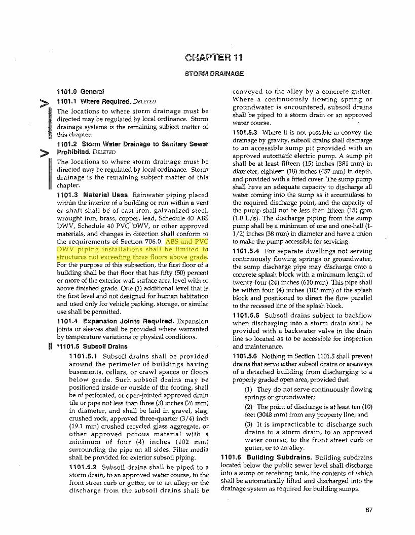
CHAPTER 14
STORM DRAINAGE
1101.0 General conveyed to the alley by a concrete gutter.
1101.1 Where Required. DELETED
The locations to where storm drainage must be directed may be regulated by local ordinance. Storm drainage systems is the remaining subject matter of this chapter.
1101.2 Worm Water Drainage to Sanitary Sewer > Prohibited. DELETED The locations to where storm drainage must be directed may be regulated by local ordinance. Storm drainage is the remaining subject matter of this chapter. 1101.3 Material Uses. Rainwater piping placed within the interior of a building or run within a vent or shaft shall be of cast iron, galvanized steel, wrought iron, brass, copper, lead, Schedule 40 ABS DWV, Schedule 40 PVC DWV, or other approved materials, and changes in direction shall conform to the requirements of Section 706.0. ABS and PVC DWV piping installations shall be limited to structures not exceeding three floors above grade. For the purpose of this subsection, the first floor of a building shall be that floor that has fifty (50) percent or more of the exterior wall surface area level with or above finished grade. One (I) additional level that is the first level and not designed for human habitation and used only for vehicle parking, storage, or similar use shall be permitted. 1101.4 Expansion Joints Required. Expansion joints or sleeves shall be provided where warranted by temperature variations or physical conditions.
11 "1101.5 Subsoil Drains 1101.5.1 Subsoil drains shall be provided around the perimeter of buildings having basements, cellars, or crawl spaces or floors below grade. Such subsoil drains may be positioned inside or outside of the footing, shall be of perforated, or open-jointed approved drain tile or pipe not less than three (3) inches (76 mm) in diameter, and shall be laid in gravel, slag, crushed rock, approved three-quarter (3/4) inch (19.1 mm) crushed recycled glass aggregate, or other approved porous material with a minimum of four (4) inches (102 mm) surrounding the pipe on all sides. Filter media shall be provided for exterior subsoil piping. 1101.5.2 Subsoil drains shall be piped to a storm drain, to an approved water course, to the front street curb or gutter, or to an alley; or the discharge from the subsoil drains shall be
where a continuously~flowing spring or groundwater is encountered, subsoil drains shall be piped to a storm drain or an approved water course. 1101.53 Where it is not possible to convey the drainage by gravity, subsoil drains shall discharge to an accessible sump pit provided with an approved automatic electric pump. A sump pit shall be at least fifteen (15) inches (381 mm) in diameter, eighteen (18) inches (457 rnrn) in depth, and provided with a fitted cover. The sump pump shall have an adequate capacity to discharge all water coming into the sump as it accumulates to the required discharge point, and the capacity of the pump shall not be less than fifteen (15) gpm (1.0 L/s). The discharge piping from the sump pump shall be a minimum of one and one-half (1- 1/2) inches (38 mm) in diameter and have a union to make the pump accessible for servicing. 1101 5.4 For separate dwellings not serving continuously flowing springs or groundwater, the sump discharge pipe may discharge onto a concrete splash block with a minimum length of twenty-four (24) inches (610 mm). This pipe shall be within four (4) inches (102 mm) of the splash block and positioned to direct the flow parallel to the recessed line of the splash block. 1101.5.5 Subsoil drains subject to backflow when discharging into a storm drain shall be provided with a backwater valve in the drain line so located as to be accessible for inspection and maintenance. 1101.5.6 Nothing in Section 1101.5 shall prevent drains that serve either subsoil drains or areaways of a detached building from discharging to a properly graded open area, provided that:
(1) They do not serve continuously flowing springs or groundwater; (2) The point of discharge is at least ten (10) feet (3048 mm) from any property line; and
(3) It is impracticable to discharge such drains to a storm drain, to an approved water course, to the front street curb or gutter, or to an alley.
1101.6 Building Subdrains. Building subdrains located below the public sewer level shall discharge into a sump or receiving tank, the contents of which shall be automatically lifted and discharged into the drainage system as required for building sumps.

1101.7- 1102.2 UNIFORM PLUMBING CODE
11 01.7 Areaway Drains. All open subsurface space adjacent to a building, serving as an entrance to the basement or cellar of a building, shall be provided with a drain or drains. Such areaway drains shall be two (2) inches (51 mm) minimum diameter for areaways not exceeding one hundred (100) square feet (9.3 ma) in area, and shall be di iarged in the manner provided for subsoil drains not serving continuously flowing springs or ground water (see Section 1101.5.2). Areaways in excess of one hundred (100) square feet (9.3 m2) shall not drain into subsoil. Areaway drains for areaways exceeding one hundred (100) square feet (9.3 m2) shall be sized according to Table 11-2. '1 101.8 Window Areaway Drains. Window areaways not exceeding ten (10) square feet (0.9 m') in area may discharge to the subsoil drains through a two (2) inch (51 mm) pipe. However, window areaways exceeding ten (10) square feet (0.9 m2) in area shall be handled in the manner provided for entrance areaways (see Section 1101.7). '1101.9 Filling Stations and Motor Vehicle Washing Establishments. Public filling stations and motor vehicle washing establishments shall have the paved area sloped toward sumps or gratings within the property lines. Curbs not less than six (6) inches (152 mm) high shall be placed where required to direct water to gratings or sumps. 1101.10 Paved Ateas. DELETED 1101.11 Roof Drainage
1101.11.1 Primary Roof Drainage. Roof areas of a building shall be drained by roof drains or gutters. The location and sizing of drains and gutters shall be coordinated with the structural design and pitch of the roof. Roof drains, gutters, vertical conductors or leaders, and horizontal storm drains for primary drainage within or on the structure shall be sized based on a storm of sixty (60) minutes duration and one hundred 100-year return period (see Appendix D). 1101.11.2 Secondary Roof Drainage
1101.11.2.1 Where parapet walls or other construction extend above the roof and create areas where storm water would become trapped if the primary roof drainage system failed to provide sufficient drainage, an independent secondary roof drainage system consisting of scuppers, standpipes, or roof drains shall be provided. Overflow drains shall be the same size as the roof drains with the inlet flow line two (2) inches (51 mm) above the low point of the roof and shall be installed independent from the roof drains.
1101.1 1.2.2 DELETED 1101.1 1.2.3 DELETED 1101.1 1.2.4 Scuppers shall be sized as rectangular weirs, using hydraulic principles to determine the required length and resulting overflow head (see Appendix D). Where standpipes are used, the head allowance required under section 1101.11.2.3 shall be not less than one and one-half (1- 112) inches (38 mm).
1101.11.3 Equivalent Systems. When approved by the Administrative Authority, the requirements of Sections 1101.11.1 and 1101.11.2 shall not preclude the installation of an engineered roof drainage system that has sufficient capacity to prevent water from ponding on the roof in excess of that allowed in the roof structural design with a rainfall rate of at least twice that for a 100-year, 60-minute storm and with a blockage in any single point in the storm drainage system.
1101.12 Cleanouts 1101.12.1 Cleanouts for building storm drains shall comply with the requirements of Section 719.0 of this Code. 1101.12.2 Rain leaders and conductors connected to a building storm sewer shall have a cleanout installed at the base of the outside leader or outside conductor before it Connects to the horizontal drain.
11 01.13 All rainwater sumps serving "public use" occupancy buildings shall be provided with dual pumps arranged to function alternately in case of overload of mechanical failure.
1102.0 Materials 1102.1 Conductors
1102.1.1 Conductors installed aboveground in buildings shall be constructed of materials specified in Table 141. 1102.1.2 The inside of conductors installed above ground leGel shall be of seamless copper water tube, Type K, L or M; Schedule 40 copper pipe or Schedule 40 copper alloy pipe; Type DWV copper drainage tube; service weight cast iron soil pipe or hubless cast iron soil pipe; standard weight galvanized steel pipe; or Schedule 40 ABS or Schedule 40 PVC plastic pipe.
11 02.2 Leaders 1102.2.1 Leaders shall be constructed of materials specified in Table 14-1. 1102.2.2 Leaders shall be of seamless copper

STORM DRAINAGE 1 102.2 - 11 06.2
water tube, Type K, L or M; Schedule 40 copper pipe; Schedule 40 copper alloy pipe; type DWV copper drainage tube; service weight cast iron soil pipe or hubless cast iron soil pipe; galvanized steel sheet metal or copper sheet metal; standard weight galvanized steel pipe; Class DL or XL lead pipe; or Schedule 40 ABS or Schedule 40 PVC plastic pipe.
1102.3 Underground Building Storm Drains. All underground building storm drains shall be constructed of materials specified in Table 14-1.
11 '1102.4 Building Storm Sewers. Building storm sewers shall be constructed of materials specified in Table 14-1.
11 *1102.5 Subsoil Drains 1102.5.1 Subsoil drains shall be constructed of materials specified in Table 14-1. 11 02.5.2 Subsoil drains shall be open-jointed or of perforated pipe, vitrified clay, plastic, cast iron, or porous concrete.
1103.0 Traps on Storm Drains and Leaders 1103.1 Where Required. Leaders and storm drains, when connected to a combined sewer, shall be trapped. Floor and area drains connected to a storm drain shall be trapped.
Exception: Traps shall not be required where roof drains, rain leaders and other inlets are at locations allowed under Section 906.0, Vent Terminals.
1103.2 Where Mot Required. No trap shall be required for a leader(s) or conductor(s) which is connected to a sewer carrying storm water exclusively. 1103.3 Trap Size. Traps, when installed for individual conductors, shall be the same size as the horizontal drain to which they are connected. 1103.4 Method of Installation of Combined Sewer. Individual storm-water traps shall be installed on the storm-water drain branch serving each storm-water inlet, or a single trap shall be installed in the main storm drain just before its connection with the combiied building sewer. Such traps shall be provided with an accessible cleanout on the outlet side of the trap.
they may be exposed to damage shall be protected by metal guards, recessed into the wall, or constructed from ferrous pipe. 1104.3 Combining Storm with Sanitary Drainage. The sanitary and storm drainage system of a building shall be entirely separate, except where a combiied sewer is used, in which case the building storm drain shall be connected in the same horizontal plane through single wye fittings to the combined building sewer at least ten (10) feet (3048 mm) downstream from any soil stack.
1105.0 Roof Drains 1105.1 Material
1105.1.1 Roof drains shall be constructed of materials specified in Table 14-1. 1105.1.2 Roof drains shall be of cast iron, copper or copper alloy, lead or plastic.
1105.2 Dome or Strainer for General Use. All roof drains and overflow drains, except those draining to I hanging gutters, shall be equipped with strainers + extending not less than four (4) inches (102 mm) above the surface of the roof immediately adjacent to the drain. Strainers shall have a minimum inlet area I above the roof level of not less than one and one-half (1-1/2) times the area of the conductor or leader to which the drain is connected. 1105.3 Strainers for Flat Decks. Roof drain strainers for use on sun decks, parking decks, and similar areas which are normally serviced and maintained may be of the flat surface-type. Such roof drain strainers shall be level with the deck and shall have an available inlet area of no less than two (2) times the area of the conductor or leader to which the drain is connected. 1105.4 Roof Draln Flashings. Connection between the roof and roof drains which pass through the roof and into the interior of the building shall be made watertight by the use of proper flashing material.
1105.4.1 Where lead flashing material is used, it shall be a minimum of four (4) pounds per square foot (19.5 kg/m2). 1105.4.2 Where copper flashing material is used, it shall be a minimum of twelve (12) ounces per square foot (3.7 kg/m2).
1106.0 Size of Leaders, Conductors, and Storm 1104.0 Leaders, Conductors, and Connections Drains 1104.1 Improper Use. Leaders or conductors shall 1106.1 Vertical Conductors and Leaders. Vertical not be used as soil, waste, or vent pipes, nor shall soil, conductors and leaders shall be sized on the basis of waste, or vent pipes be used as leaders or conductors. the maximum projected roof area and Table 11-1. 1104.2 Protection of Leaders. Leaders installed *1106.2 Size of Horizontal Storm Drains and 11 along alleyways, driveways, or other locations where Sewers. The size of building storm drains or

UNIFORM PLUMBING CODE
Size of Drain, Leader or Pipe,
Inches
Size of Drain Leader or Pipe,
mm
Flow,
gpm
Flow, u s
TABLE 11-1 Sizing Roof Drains, Leaders, and Vertical Rainwater Piping
Maximum Allowable Horizontal Projected Roof Areas Square Feet at Various Rainfall Rates
1 " h r 2"hr 3"hr 4"hr 5"hr 2176 1088 725 544 435 6440 3220 2147 1610 1288
13,840 6920 4613 3460 2768 25,120 12,560 8373 6280 5024 40,800 20,400 13,600 10,200 8160 88,000 44,000 29,333 22,000 17,600 1
TABLE 11-1 (Metric) Sizing Roof Drains. Leaders, and Vertical Rainwater Piping
Maximum Allowable Horizontal Projected Roof Areas Square Meters at Various Rainfall Rates
Notes: 1. The sizing data for vertical conductors, leaders, and drains is baaed on the pipes flowing 7/24 full. 2. For rainfall rates other than those listed, determine the allowable roof area by dividing the area given in the
I inchhour (25 mmhour) column by the desired rainfall rate. 3. Vertical piping may be round, square, or rectangular. Square pipe shall be sized to enclose its equivalent
round pipe. Rectangular pipe shall have at least the same cross-sectional area as its equivalent round pipe. except that the ratio of its side dimensions shall not exceed 3 to 1.

STORM DRAINAGE Table 1 1-2
Size of Pipe,
inches
Size of Pipe,
lnches
Size of Pipe,
lnches
TABLE 11-2 Sizing of Horizontal Rainwater Piping
Flow at Maximum Aliowable Horizontal Projected Roof Areas 118"Ift. Slope, Square Feet at Various Rainfall Rates
gpm 1 "lhr 2"lhr 3"hr 4"lhr 5"hr 6"lhr
34 3288 1644 1096 822 857 548 78 7520 3760 2506 1880 1504 1253 139 13,360 6680 4453 3340 2672 2227 222 21,400 10,700 7133 5350 4280 3566 478 46,000 23.000 15,330 11,500 9200 7670 860 82,800 41,400 27,600 20,700 16,580 13,800 1384 133,200 66,600 44,400 33,300 26,650 22,200 2473 238.000 1 1 9,000 79,333 59,500 47,600 39,650
Flow at Maximum Allowable Horizontal Projected Roof Areas 114"lft. Slope, Square Feet at Various Rainfall Rates
gpm 1 "lhr 2"Ihr 3"Ihr 4"Ihr 5"Ihr 6"lhr
48 4640 2320 1546 1160 928 773 110 10,600 5300 3533 2650 2120 1766 196 18,880 9440 6293 4720 3776 3146 314 30,200 15,100 10.086 7550 6040 5033 677 65,200 32,600 21,733 16,300 13,040 10.866 1214 116,800 58,400 38,950 29,200 23,350 19,450 1953 188.000 94,000 62,600 47,000 37,600 31,350 3491 336,000 168,000 11 2,000 84,000 87.250 56.000
Flow at Maximum Allowable Horizontal Projected Roof Areas 112"lft. Slope, Square Feet at Various Rainfall Rates
gpm 1 "Ihr 2"lhr 3"hr 4"lhr 5"lhr
68 6576 3288 2192 1644 1310 156 15,040 7520 5010 3760 3010 278 26,720 13,360 8900 6680 5320 445 42,800 21,400 14,267 10,700 8580 956 92,000 46,000 30,650 23,000 18,400 1721 165,600 82,800 55.200 41,400 33,150 2768 266,400 133,200 88,800 66,600 53.200 4946 476.000 238,000 158,700 119,000 95.200
Notes: 1. The sizing data for horizontal piping is based on the pipes flowing full. 2. For rainfall rates other than those listed, determine the allowable roof area by dividing the area given in the
1 inchlhour (25 mmlhour) column by the desired rainfall rate.

Table 1 1-2 (Metric) UNIFORM PLUMBING CODE
TABLE 11-2 (Metric) Sizing of Horizontal Rainwater Piping
Size of Flow at Maximum Allowable Horizontal Projected Roof Areas Pipe, 10 mm/m Slope, Square Meters at Various Rainfall Rates mm Us
25mmlhr 5Ommhr 75mmlhr 100mmhr 125mmlhr 150mmlhr 75 2.1 305 153 1 02 76 61 51 100 4.9 700 350 233 175 140 116 125 8.8 1241 621 414 310 248 207 150 14.0 1988 994 663 497 398 331 200 30.2 4273 2137 1424 1068 855 713 250 54.3 7692 3846 2564 1923 1540 1282 300 87.3 12,375 61 87 41 25 3094 2478 2062 375 156.0 22,110 11,055 7370 5528 4422 3883
Size of Flow at Maximum Allowable Horizontal Projected Root Areas Pipe, 20 mm/m Slope, Square Meters at Various Rainfall Rates mm u s
25mmlhr M)mmhr 75mmhr 1 Wmmlhr 125mmlhr 150mm/hr 75 3.0 431 216 144 108 86 72 100 6.9 985 492 328 246 197 164 125 12.4 1 754 877 585 438 35 1 292 1 50 19.8 2806 1403 935 701 561 488 200 42.7 6057 3029 201 9 1514 1211 1009 250 76.6 10,851 5425 3618 2713 21 69 1807 300 123.2 17,465 8733 581 6 4366 3493 2912 375 220.2 31,214 15.607 10,405 7804 6248 5202
Size of Flow at Maximum Allowable Horizontal Projected Roof Areas Pipe, 40 mmlm Slope, Square Meters at Various Rainfall Rates mm Us
25mmlhr 50mmhr 75mmlhr 100mm/hr 125mmlhr 1SOmmhr 75 4.3 61 1 305 204 1 53 1 22 1 02 100 9.8 1400 700 465 350 280 232 125 17.5 2482 1241 827 621 494 41 3 150 28.1 3976 1988 1325 994 797 663 200 60.3 8547 4273 2847 2137 1709 1423 250 108.6 15,390 7695 5128 3846 3080 2584 300 174.6 24,749 12,374 8250 6187 4942 4125 375 312.0 44,220 22,110 14,753 11.055 8853 7367
Notes: 1. The sizing data for horizontal piping is based on the pipes flowing full. 2. For rainfall rates other than those listed, determine the allowable roof area by dividing the area given in the
1 inchlhour (25 mrnlhour) column by the desired rainfall rate. i(

STORM DRAINAGE Table 11 -3
TABLE 11-3 Size of Gutters
Diameter of Gutter in lnches
1116"lft. Slope 3 4 5 6 7 8 10
Maximum Rainfall in lnches per Hour 2 3 4 5
340 226 170 1 36 720 480 360 288
1250 834 625 500 1920 1280 960 768 2760 1840 1380 1100 3980 2655 1990 1590 7200 4800 3600 2880
Diameter of Gutter in Inches Maximum Rainfall in Inches per Hour
118"lft. Slope 2 3 4 5 3 480 320 240 192 4 1020 681 51 0 408 5 1760 1172 880 704 6 2720 1815 1360 1085 7 3900 2600 1950 1560 8 5600 3740 2800 2240 10 10.200 6800 5100 4080
Diameter of Gutter in Inches Maximum Rainfall in Inches per Hour
114"lft. Slope 2 3 4 5 3 680 454 340 272 4 1440 960 720 576 5 2500 1668 1250 1000 6 3840 2560 1920 1536 7 5520 3680 2760 2205 8 7960 5310 3980 3180 10 14,400 9600 7200 5750
Diameter of Gutter in Inches Maximum Rainfall in Inches per Hour
112"m. Slope 2 3 4 5 3 960 640 480 384 4 2040 1360 1020 816 5 3540 2360 1770 1415 6 5540 3695 2770 2220 7 7800 5200 3900 3120 6 11,200 7460 5600 4480 10 20.000 13,330 10,000 6000

Table 1 1-3 (Metric) UNIFORM PLUMBING CODE
Diameter of Gutter in mm
5.2 m d m Slope 76.2 101.6 127.0 152.4 177.8 203.2 254.0
Diameter of Gutter in mm
10.4 m d m Slope 76.2 101.6 127.0 152.4 177.8 203.2 254.0
Diameter of Guner in mm
20.9 m d m Slope 76.2 101.6 127.0 152.4 177.8 203.2 254.0
TABLE 11-3 (Metrlc) Size of Gutters
-Maximum Rainfall in Millimeters per Hour 50.8 76.2 101.6 127.0 152.4 31.6 21 .O 15.8 12.6 10.5 66.9 44.6 33.4 26.8 22.3
116.1 77.5 58.1 46.5 38.7 178.4 119.1 89.2 71.4 59.5 256.4 170.9 128.2 102.2 85.3 369.7 246.7 184.9 147.7 123.1 668.9 445.9 334.4 267.6 223.0
Maximum Rainfall in Millimeters per Hour
50.8 76.2 101.6 127.0 152.4 44.6 29.7 22.3 17.8 14.9 94.6 63.3 47.4 37.9 31.6
163.5 108.9 81.8 65.4 54.5 252.7 168.6 126.3 100.8 84.1 362.3 241.5 181.2 144.9 120.8 520.2 347.5 260.1 208.1 173.7 947.6 631.7 473.8 379 315.9
Maximum Rainfall in Millimeters per Hour 50.8 76.2 101.6 127.0 152.4 63.2 42.2 31.6 25.3 21 .O
133.8 89.2 66.9 53.5 44.6 232.3 155.0 116.1 92.9 77.5 356.7 237.8 178.4 142.7 118.9 512.8 341.9 256.4 204.9 170.9 739.5 493.3 369.7 295.4 246.7 133.8 891.8 668.9 534.2 445.9
Diameter of Gutter in mm Maximum Rainfall in Millimeters per Hour
41.7 mmlm Slope 50.8 76.2 101.6 127.0 152.4 76.2 89.2 59.5 44.6 35.7 29.7 101.6 189.5 126.3 94.8 75.8 63.2 127.0 328.9 219.2 164.4 131.5 109.6 152.4 514.7 343.3 257.3 206.2 171.9 177.8 724.6 483.1 362.3 289.9 241.4 203.2 1040.5 693.0 520.2 416.2 346.5 254.0 1858.0 1238.4 929.0 743.2 618.7

STORM DRAINAGE
building storm sewers or any of their horizontal branches shall be based upon the maximum projected
> roof area to be handled and Table 11-2. 1106.3 Size of Roof Gutters. The size of semicircular gutters shall be based on the maximum projected roof area and Table 11-3. 1106.4 Side Walls Draining onto a Roof. Where vertical walls project above a roof so as to permit storm water to drain to the roof area below the adjacent roof area may be computed from Table 11-1 as follows:
(1) For one (1) wall - add fifty (50) percent of the wall area to the roof area figures. (2) For two (2) adjacent walls - add thirty-five (35) percent of the total wall areas. (3) Two (2) walls opposite of same height - add no additional area. (4) Two (2) walls opposite of differing heights - add fifty (50) percent of wall area above top of lower wall.
(5) Walls on three (3) sides - add fifty (50) percent of area of the inner wall below the top of the lowest wall, plus allowance the for area of wall above top of lowest wall, per (2) and (4) above.
(6) Walls on four (4) sides - no allowance for wall areas below top of lowest wall - add for areas above the top of the lowest wall per (I), (2), (4) and (5) above.
11 *1107.0 Values for Continuous Flow Where there is a continuous or semi-continuous discharge into the building storm drain or building storm sewer, as from a pump, ejector, air- conditioning plant, or similar device, one (1) gpm (3.8 L/min.) of such discharge shall be computed as being equivalent to twenty-four (24) square feet (2.2 m2) of roof area, based upon a rate of rainfall of four (4) inches (102 mm) per hour.
1108.0 Controlled-Flow Roof Drainage 1108.1 Application. In lieu of sizing the storm drainage system in accordance with Section 1106.0, the roof drainage may be sized on the basis of controlled flow and storage of the storm water on the roof, provided the following conditions are met:
(1) The water from a 25-year frequency storm shall not be stored on the roof for more than twenty-four (24) hours.
(2) During the storm, the water depth on the roof shall not exceed the depths specified in Table 11-4.
TABLE 11-4 Controlled Flow Maximum Roof Water Depth
Roof Rise,* Max Water Depth at Drain,
Inches (mm) Inches (mm) Flat (Flat) 3 (76) 2 (51) 4 (102) 4 (102) 5 (127s) 6 (152) 6 (152)
'Vertical measurement from the roof surface at the drain to the highest point of the roof surface served by the drain, ignoring any local depression immediately adjacent to the drain.
(3) No less than two (2) drains shall be installed in roof areas of ten thousand (10,000) square feet (929.0 m2) or less, and no less than one (1) additional drain shall be installed for each ten thousand (10,000) square feet (929.0 m') ,of roof area over ten thousand (10,000) square feet (929.0 m2). (4) Each roof drain shall have a pre-calibrated, fixed (non-adjustable), and proportional weir (notched) in a standing water collar inside the strainer. No mechanical devices or valves shall be allowed. (5) Pipe sizing shall be based on the pre- calibrated rate of flow (gpm) of the pre- calibrated weir for the maximum allowable water depth, and Tables 11-1 and 11-2. (6) The height of stones or other granular material above the waterproofed surface shall not be considered in water depth measurement, and the roof surface in the vicinity of the drain shall not be recessed to create a reservoir. (7) Roof design, where controlled flow roof drainage is used, shall be such that the minimum design roof live load is thirty (30) pounds per square foot (146.5 kg/m2) to provide a safety factor above the fifteen (15) pounds per square foot (73.2 kg/m2) represented by the depth of water stored on the roof as indicated in Table 11-4. (8) Scuppers shall be provided in parapet walls. The distance of scupper bottoms above the roof level at the drains shall not exceed the maximum distances specified in Table 11-5.

Table 11-5 - 1109.2 UNIFORM PLUMBING CODE
TABLE 11-5 Distance of Scupper Bottoms Above Roof
Maximum Distance of Scupper Bonom
Roof Rise,' Above Roof Level at Drains,
Inches (mm) Inches (mm) Flat (Flat) 3 (76.2) 2 (51) 4 (102) 4 (102) 5 (127.0) 6 (152) 6 (152)
"Vertical measurement from the roof surface at the drain to the highest point of the roof surface Sewed by the drain, ignoring any local depression immediately adjacent to the drain.
(9) Scupper openings shall be a maximum of one (1) inch (25.4 mm) high. A sufficient number of scuppers shall be provided so that the total scupper cross-sectional area is at least equal to that required for horizontal storm drains in Table 11-2 (column for half (1/2) inch (12.7 mm) slope). (10) Flashings shall extend above the top of the scuppers. (11)At any wall or parapet, forty-five (45) degree (0.79 tad) cants shall be installed. (12)Separate storm and sanitary drainage systems shall be provided within the building. (13) Calculations for the roof drainage system shall be submitted along with the plans to the Administrative Authority for approval.
11 (14) Compliance with the building code. 1108.2 Setback Roofs. Drains on setback roofs may be connected to the controlled flow drainage systems provided:
(1) The setback is designed for storing water, or (2) The square footage of the setback drainage area is converted as outlined in Section 1108.0 to gpm, and the storm water pipe sizes in the controlled flow system are based on the sum of the loads.
(3) The branch from each of the roof drains that are not provided with controlled flow shall be sized in accordance with Table 11-1.
1109.0 Testing 1109.1 Testing Required. New building storni drainage systems and parts of existing systems that have been altered, extended or repaired shall be
tested as described in Section 1109.2.1 to disclose leaks and defects. 1109.2 Methods of Testing Storm Drainage
i Systems. Except for outside leaders and perforated or open jointed drain tile, the piping of storm drain systems shall be tested upon completion of the rough piping installation by water or air, and proved tight. The Administrative Authority may require the removal of any cleanout plugs to ascertain if the pressure has reached all parts of the system. Either of the following test methods shall be used:
1109.2.1 Water Test. After p~ping has been installed, the water test shall be applied to the drainage system, either in its entirety or in sections. If applied to the entire system, all openings in the piping shall be tightly closed except for the highest opening, and the system shall be filled with water to the point of overflow. If the system is tested in sections, each opening shall be tightly plugged except for the highest opening of the section under test, and each section shall be filled with water, but no section shall be tested with less than a ten (10) foot (3048 mm) head of water. In testing successive sections, at least the upper ten (10) foot (3048 mm) of the next preceding section shall be tested so that no joint of pipe in the building (except the uppermost ten (10) foot (3048 mm) of a roof drainage system, which
((
shall be filled with water to the flood level of the uppermost roof drain) shall have been submitted to a test of less than a ten (10) foot (3048 mm) head of water. The water shall be kept in the system or in the portion under test for at least fifteen (15) minutes before inspection starts; the system shall then be tight at all points. 1109.2.2 Air Test. The air test shall be made by attaching an air compressor testing apparatus to any suitable opening after closing all other inlets and outlets to the system, forcing air into the system until there is a uniform gage pressure of five (5) psi (34.5 kPa) or sufficient to balance a column of mercury ten (10) inches (254 mm) in height. This pressure shall be held without introduction of additional air for a period of at least fifteen (15) minutes. Schedule 40 plastic DWV systems shall not be tested by the air test method. 1109.2.3 Exceptlons. DELETED Alternative methods of testing storm drainage systems complying with the intent of this code shall be submitted to the Office of the State i Building Commissioner in accordance with the General Administrative Rules (675 IAC 124-11). 1

CHAPTER 12
FUEL PIPING
> <Chapter 12 is not adopted by the State of Indiana.)
11 See the Indiana Mechanical Code 675 IAC 18 for fuel piping.

UNIFORM PLUMBING CODE

CHAPTER 13
MEDICAL GAS SYSTEMS
> <Chapter 13 is not adopted by the State of Indiana.)
11 See the building code, 675 IAC 13, and the 1998 Indiana Fire Code, 675 IAC 22, for medical gas systems.

UNIFORM PLUMBING CODE

CHAPTER 14
MIANDATORYREFERENCEDSTANDARDS
Table of Contents for Table 14-1
Title > Backfiow Preventers (see Valves and Appurtenances)
Page
Backwater Valves (see Interceptors and Backwater Valves) Cleanouts(see Traps and Cleanouts) Drainage System . Sanitary ............................................................................................................................. 82
Drains . Storm ................................................................................................................................................. 88 Building . Below Ground ............................................................................................................................ 84
Interior - Above Ground ............................................................................................................................. 98 Drains - Subsoil ............................................................................................................................................... 89 Fixtures and Trim - Plumbing .......................................................................................................................... 90
Hangers and Supports .................................................................................................................................... 93 Indirect Waste Piping and Special Wastes ....................................................................................................... 93 Interceptors and Backwater Valves .................................................................................................................. 96
Joining Materials and Methods > Sanitary Drainage Systems ........................... : ......................................................................................... 86
Sanitary Vents .......................................................................................................................................... 103 Storm Drains ............................................................................................................................................ 100
............................................................................................................................................ Subsoil Drains 90
Water Supply System .............................................................................................................................. 109 Joining Methods - Indirect Waste Piping and Special Waste ......................................................................... 95 Manholes .......................................................................................................................................................... 97
................................................................................................................................................... > Miscellaneous 97 Pumps ............................................................................................................................................................. 98
Roof Drains .................................................................................................................................................... 89 Sewer. Building (see Drainage System - Sanitary) > Traps and Cleanouts .................................................................................................................................... 101 Valves and Appurtenances ............................................................................................................................ 108 Vents and Venting .......................................................................................................................................... 103
Water Supply Systems ................................................................................................................................... 104
Wrapping and Coating .................................................................................................................................... 1 1
Footnotes to standards listed in Table 14-1 and abbreviations are at the end of the table .

UNIFORM PLUMBING CODE
TABLE 14-1
Standards for Materials, Equipment, Joints and Connections
Where more than one standard has been listed for the same material or method. the relevant portions of all such standards shall apply. .. .
Item I ANSI
> Water Heaters
Water heater rellef valve drain tubes
9 ,
Electric Booster and Commercial Storage Tank Water Heaters I UL 1453-94
Gas. Volume I, automatic storage-type water heaters w~th lnput of 75,030 BTUM (22 kW), or les 221.10.1a.94 I Gas, Volume Ill, circulating tank instantaneous and large automatic type water heaters
Electric
Oil
221.10.3a-94 221.10.32-90 221.10.3b-92
DRAINAGE SYSTEM -SANITARY
Bullding Sewers
Cast iron soil pipe and fittings - hub and spigot
Gas Fired Low-Pressure Steam and Hot Water Boilers and Addenda
Hubless cast iron sanitary system
221.13-91
A 74-93 (Note 1)
Ductile iron pipe centrifugally cast in sand-lined I AWWA C1511 I A 377-89 or metal molds A21.51-91 I
ClSPl301-90 ClSPl310-90
IAPMO IS 6-95
Ductile iron or grey iron fittings
Ductile iron compact fittings
Clay pipe
Asbestos-cement nonpressure sewer pipe I
AWWA C1531 A21.53-88
A106.6-70
Copper alloy sand casting for general application 1 Seamless copper water tube
Copper drainage tube
Cast copper alloy solder joint drainage fittings
Wrought copper and copper alloy solder-joint drainage fittings
ASME 816.23-92
ASME 816.29-86 (Note 1)
I C 428-92 (Notes 6 8 7) I
B 584-936 (Note 5)
B 88-93a
B 306-92
IAPMO IS 18-85
IAPMO IS 3-93
IAPMO IS 3-93

MANDATORYREFERENCEDSTANDARDS Table 14-1
Item
Concrete sewer, storm drain and culvert pipe
Low pressure air test for building sewers (Installation)
Plastic, ABS
Acrylonitrile-Butadiene-Styrene (ABS) Sch. 40 plastic drain, waste and vent pipe and fittings
Acrylonitrile-Butadiene-Styrene (ABS) sewer pipe and fittings
Acrylonitrile-Butadiene-Styrene (ABS) Sch. 40 plastic drain, waste and vent pipe having a foam core
Acrylonitrile-Butadiene-Styrene (ABS) composite sewer piping
Plastic, PVC
Poiy (vinyl chloride) (PVC) plastic drain, waste and vent pipe and fittings
Type PSP poly (vinyl chloride) (PVC) sewer pipe and fittings
Type PSM poly (vinyl chloride) (PVC) sewer pipe and fittings
Poly (vinyl chloride) (PVC) sewer pipe and fittings
Type PS-46 poly (vinyl chloride) (PVC) plastic gravity flow sewer pipe and fittings
Coextruded poly (vinyl chloride) (PVC) plastic pipe with a cellular core
Poly (vinyl chloride) (PVC) corrugated sewer pipe with a smooth interior and fittings
Building Drains Above Ground
Cast iron soil pipe and fittings - hub and spigot
Hubless cast iron sanitary system
Shielded couplings joining hubless cast iron soil pipe and fittings
Ductile iron pipe centrifugally cast in sand-lined or metal molds
Ductile iron or grey iron fittings
Ductile iron compact fittings
Copper alloy sand casting for general applications
Seamless copper water tube
Copper drainage tube
ASTM
C 14-92
D 2661-94a (Note 1)
D 2751-93 (Note 1)
F 628-93 (Notes 1 & 3)
D 2680-93
D 2665-94
D 3033-85 (D)
D 3034-94
D 2729-93 (Note 1)
F 789-89 (Note 1)
F 891-93a (Notes 1 & 3)
F 949-93a
A 74-93 (Note 1)
C 564-95a
C 1277-94
A 377-89
A 377-89
B 584-93b (Note 5)
B 66-93a
B 306-92
ANSI
NSF 14-90
NSF 14-90
NSF 14-90
NSF 14-90
NSF 14-90
NSF 14-90
NSF 14-90
NSF 14-90
AWWA C1511 A21.51-91
AWWA C1101 A21.10-93
AWWA 1531 A21.53-68
Other
IAPMO IS 16-84
IAPMO 13 1-91 IAPMO IS 5-92
IAPMO IS 11-87 IAPMO IS 1-91
IAPMO IS 1-91 IAPMO IS 5-92
IS 1-91
IAPMO IS 1-91 IAPMO IS 9-95
IAPMO IS 1-91
IAPMO IS 1-91
IAPMO IS 1-91
IAPMO IS 1-91
IMbPMO IS 1-531 IAPMO IS 9-95
IAPMO IS 1-91
CiSPl H5N-85
ClSPl310-90 ClSPl301-90 (Note 1
IAPMO IS 6-95)
IAPMO IS 3-93
IAPMO IS 3-93

Table 14-1 UNIFORM PLUMBING CODE
item
Seamless copper tube
Seamless brass tube
Cast bronze solder-joint drainage fittings
Wrought copper and copper alloy solder-joint drainage fittings
Steel pipe (galvanized)
Cast iron threaded drainage fittings
Lead pipe and bends
Plastic, ABS Aciylonitrile-Butadiene-Styrene (ABS) Sch. 40 plastic drain, waste and vent pipe and fittings
Aciylonitrile-Butadiene-Styrene (ABS) Sch. 40 plastic drain, waste and vent pipe having a foam core
Plastic, PVC Poly (vinyl chloride) (PVC) plastic drain, waste and vent pipe and fittings
Coextruded poly (vinyl chloride) (PVC) plastic pipe with a cellular core
Building Drains - Below Ground
Cast iron soil pipe and fittings - hub and spigot
Hubiess cast iron sanitary system
Ductile iron pipe centrifugally cast in sand-lined or metal molds
Ductile iron or grey iron fittings
Ductile iron compact fittings
Copper alloy sand casting for general applications
Seamless copper water tube
Copper drainage tube
Cast bronze solder-joint drainage fittings
Wrought copper and copper alloy solder-joint drainage fittings
Lead pipe and bends
Plastic, ABS
Acrylonitrile-Butadiene-Styrene (ABS) Sch. 40 plastic drain, waste and vent pipe and fittings
Acrylonitrile-Butadiene-Styrene (ABS) Sch. 40 plastic drain, waste and vent pipe having a loam core
Plastic, PVC
ANSI
ASME 816.23-92
ASME B1 6.29-86 (Note 1)
ASME B36.1585
ASME 816.12-91 (Note 1)
NSF 14-90
NSF 14-90
NSF 14-90
AWWA C1511 A21.51-91
AWWA C1101 A21.10-93
AWWA C1531 A21.53-88
ASME 816.23-92
ASME 616.29-86 (Note 1)
NSF 14-90
NSF 14-90
ASTM
B 75-93
B 135-91
A 53-93a A 120-64 (D)
D 2661-94a (Note 1)
F 628-93 (Notes 1 8 3)
D 2665-94
F 891 -93a
A 74-93 (Note 1)
C 564-95a
A 377-89
A 377-89
B 584-936 (Note 5)
B 88-93a
B 306-92
D 2661-94a (Note 1)
F 626-93 (Notes 1 &3)
Other
IAPMO IS 3-93
IAPMO IS 3-93
WW-P 3258-76
IAPMO IS 5-92
IAPMO IS 5-92
IAPMO IS 9-95
IAPMO IS 9-95
ClSPl HSN-85
ClSPl310-90 ClSPl301-90 (Note 1)
IAPMO IS 6-95
IAPMO IS 3-93
IAPMO IS 3-93
IAPMO IS 3-93
WW-P-3250-76
IAPMO IS 5-92
IAPMO IS 5-92

MANDATORYREFERENCEDSTANDARDS Table 14-1
Poly (vinyl chloride) (PVC) plastic drain, waste and vent pipe and fittings IAPMO IS 9-95
Coextruded poly (vinyl chloride) (PVC) plastic pipe with a cellular core IAPMO IS 9-95
Sanitary Drain and Waste - Above Ground
Cast iron soil pipe and fittings hub and spigot CISPI HSN-85
Hubless cast iron sanitary system CISPI 310-90 CISPI 301-90 (Note 1)
IAPMO IS 6-95
Ductile iron pipe centrifugally cast in sand-lined AWWA C151/ or metal molds
Ductile iron or grey iron fittings AWWA C1101
Ductile iron compact fittings
Copper alloy sand casting for general applications B 584-93b (Note 5)
Seamless copper water tube IAPMO IS 3-93 Copper drainage tube IAPMO IS 3-93 Cast bronze solder-joint drainage fittings ASME 81 6.23-92
Wrought copper and copper alloy solder-joint drainage fittings ASME 816.29-86 (Note 1) IAPMO IS 3-93
Cast bronze solder-joint fittings for solvent drainage systems ASME B16.32-92
Copper alloy fixture fittings A112.18.1M-94
Lead pipe and bends
Steel pipe (galvanized)
Cast iron threaded drainage fittings
ABS and PVC piston driven DWV expansion joints
Plastic, ABS
Acrylonitrile-Butadiene-Styrene (ABS) Sch. 40 plastic drain, waste and vent pipe and fittings
Acrylonitrile-Butadiene-Styrene (ABS) Sch. 40 plastic drain, waste and vent pipe having a foam core
Plastic, PVC
Poly (vinyl chloride) (PVC) plastic drain, waste and vent pipe and fittings
Coextruded poly (vinyl chloride) (PVC) plastic pipe with a cellular core
Sanltaiy Drain and Waste - Below Ground
Cast iron soil pipe and fittings hub and spigot
Hubless cast iron sanitary system
ASME B36.1 OM-85
ASME 816.12-91
NSF 14-90
NSF 14-90
NSF 14-90
A 53-93a A 120.84 (D)
D 2661-94a (Note 1)
F 626-93 (Notes 1 8 3)
D 2665-94
F 891 -93a
A 74-93 (Note 1)
WW-P-325B-76
IAPMO PS 51 -92
IAPMO IS 5-92
IAPMO IS 5-92
IAPMO IS 9-95
IAPMO IS 9-95
CISPI HSN-85
CISPI 301 -90 (Note 1) CISPI 310-90
IAPMO IS 6-95

Table 14-1 UNIFORM PLUMBING CODE
AWWAC1511
AWWA C1101
Ductile iron compact fittings AWWA C1531
Copper alloy sand casting for general applications B 584-93b (Note 5)
Seamless copper water tube IAPMO IS 3-93
Copper drainage tube IAPMO IS 3-93
Cast bronze solder-joint drainage fittings ASME B1 6.23-92 IAPMO IS 3-93
Copper flush pipes ASME A1 12.18.1M-94
Wrought copper and copper alloy solder-joint drainage fittings IAPMO IS 3-93
Cast bronze solder-joint fittings for solvent drainage systems
Lead pipe, lead traps and bends WW-P-3256-76
Cast iron threaded drainage fittings
Plastic, ABS
Acrylonitrile-Butadiene-Styrene (ABS) Sch. 40 plastic drain. waste and vent pipe and fittings
Acrylonitrile-Butadiene-Styrene (ABS) Sch. 40 plastic drain, waste and vent pipe having a foam core
Plastic. PVC
Poly (vinyl chloride) (PVC) plastic drain, waste and vent pipe and fittings
Coextruded poly (vinyl chloride) (PVC) plastic pipe with a cellular core
JOINING MATERIALS AND METHODS - SANITARY DRAINAGE SYSTEMS Type "F clamps for plumbing applications
Rubber gasket joints for ductile-iron and gray-iron pressure pipe and fittings
Cast iron soil pipe and fittings hub and spigot neoprene compression gaskets, caulking, lead wool and lead pig
Threaded joints (IPS)
Hubiess cast iron sanitary systems neoprene gasket and stainless steel shield
Flexible transition couplings tor underground piping systems
Shielded transition couplings for use with dissimilar DWV pipe and fittings above ground
NSF 14-90
SAE J1670-93
AWWACll l A21 .I 1-90
ASME B1.lO.l-83 81 '20.3-91
D 2665-94
F 891 -93a
C 564-95a B 29-92
C 564-95a
C 1 173.95
IAPMO IS 9-95
IAPMO IS 9-95
ClSPl HSN-85
ClSPl310-90 ClSPi 301-90 (Note 1)
IAPMO IS 6-95
IAPMO PS 44-92

MANDATORYREFERENCEDSTANDARDS Table 14-1
Clay pipe
Brazing filler metals
Solder metal and wiping solder
Silver brazing joints for wrought and cast solderjoint fittings
Flux brazing
Flux soldering
Seal compound pipe joint and thread
Plastic DWV, ABS
Acrylonitrile-Butadiene-Styrene (ABS) Sch. 40 plastic drain, waste and vent pipe and fittings
Acryionitrile-Butadiene-Styrene (ABS) Sch. 40 plastic drain, waste and vent pipe having a foam core
Solvent cement for Acrylonitrile-Butadlene. Styrene (ABS) plastic pipe and fittings
Joints for drain and sewer plastic pipes using flexlble elastomeric seals
Plastlc DWV, PVC
Poly (vinyl chloride) (PVC) plastic drain, waste and vent pipe and fittings
Solvent cement for poly (vinyl chloride) (PVC) plastic pipe and fittings
Primers for use in solvent cement joints of poly (vinyl chloride) (PVC) plastic pipe and fittings
Making solvent-cemented joints with poly (vinyl chloride)(PVC) pipe and fittings
Jolnts for drain and sewer plastic pipes using flexlble elastomeric seal?
Plastic Sewer, ABS
Solvent cement lor Acrylonitrile-Butadiene. Styrene (ABS) plastlc pipe and fittings
Joints for drain and sewer plastic pipes using flexible elastomeric seals
Underground installation of flexible thermo- ptastic sewer pipe
Joints for drain and sewer plastic pipes using flexible elastomeric seals
Plastic Sewer, PVC
Solvent cement for poly (vinyl chloride) (PVC) plastic pipe and fittings
Primers for use In solvent cement joints of poly (vinyl chloride) (PVC) plastic pipe and fittings
Underground installation of flexible thermo. plastic sewer pipe
Jolnts for drain and sewer plastic pipes using flexible elastomeric seals
ANSI
AWS A5.8-92
NSF 14-90
NSF 14-90
NSF 14-90
NSF 14-90
NSF 14-90
NSF 14-90
NSF 14-90
NSF 14-90
NSF 14-90
ASTM
C 425-90a
B 32-95a (Note 4)
3 2661 -94a (Note 1 )
628-93 (Notes 1 & :
D 2235-93a
D 3212-92
Other
IAPMO IS 18-85
IAPMO IS 5-92
IAPMO IS 5-92
IAPMO IS1 1-87 IAPMO IS 5-92 e
IAPMO IS 9-95
IAPMO IS 9-95
IAPMO IS 9-95
< IAPMO IS 9-95

Table 14-1 UNIFORM PLUMBING CODE
Making solvent-cemented joints wilh poly (vinyl chloride) (PVC) pipe and fillings I . . . . . > Underground installation of flexible thermo- plastic sewer pipe I Joints for drain and sewer plastic pipes using flexible elastomeric seals I Plastic stabilizers for use with plastic closet bends I Mechanical cast iron closet flanges I
Pumps - Drainage I Sewage pump, centrifugal, wet pit I Sump pumps. vertical, wet pit I
Sewage Ejectors
Mechanical and air
DRAINS -STORM I Building Storm Sewers
Joints for circular concrete sewer and culvert pipe. using ~ b b e r gaskets
Cast iron soil pipe and fillings hub and spigot
Hubless cast iron sanitary system I Flexible transition couplings for underground piping systems I Ductile iron pipe centrifugally cast in sand-lined or metal molds I Ductile iron or grey iron linings I Ductile iron compact fittings I Clay pipe I Asbestos-cement nonpressure sewer pipe
Copper alloy sand casting for general application
Seamless copper water tube (types K, Land M) I Copper drainage tube-type DWV
Cast copper alloy solder joint drainage fittings
Wrought copper and copper alloy solder-joint drainage fittings
Concrete sewer, storm drain and culvert pipe
Low pressure air test for building sewers (Installation) I Plastic, ABs I
ANSI
AWWA C i 101 A21 .lo-93
AWWA C1531 A21.53-88
ASME B16.23-92
ASME 816.29-86 (Note
I ASTM 1 Other
1)
C 443-85a(R90)
A 74-93 (Note 1) C 564-95a
C 564-95a
C 11 73-95
A 377-89
A 377-89
C 700-91 C 425-9Oa
C 428-92 (Notes 6 & 7)
B 584-931, (Note 5)
B 88-93a
B 306-92
C 14-92
IAPMO PS 91-95
IAPMO PS 97-96
MIL-P-21214B-92
ClSPl HSN-85
ClSPl301-90 (Note 1) ClSPl310-90
IAPMO IS 6-95
IAPMO IS 1-91 IAPMO IS 18-85
IAPMO IS 3-93
IAPMO IS 3-93
IAPMO IS 3-93
IAPMO IS 3-93
IAPMO IS 16-84

MANDATORYREFERENCEDSTANDARDS Table 14-1
Acrylonitrile-Butadiene-Styrene (ABS) sewer IAPMO IS1 1-87 pipe and fitlings
Acrylonitrile-Butadiene-Styrene (ABS) Sch. 40 plastic drain, waste and vent pipe having a IAPMO IS 5-92 foam core
Acrylonitrile-Butadiene-Styrene (ABS) composite sewer pipe IAPMO IS 1-91
Plastic, PVC Poly (vinyl chloride) (PVC) plastic drain. IAPMO IS 9-95 waste and vent pipe and fittings IAPMO IS 1-91
Type PSP poly (vinyl chloride) (PVC) sewer pipe and fittings IAPMO IS 1-91
Type PSM poly (vinyl chloride) (PVC) sewer pipe and fittings IAPMO IS 1-91
Type PS-46 poly (vinyl chloride) (PVC) plastic gravity flow sewer pipe and fittings F 789-89 (Note 1) IAPMO IS 1-91
Coextruded poly (vinyl chloride) (PVC) plastic IAPMO IS 1-91 pipe with a cellular core IAPMO IS 9-95
Poly (vinyl chloride) (PVC) corrugated sewer pipe with a smooth interior and fittings IAPMO IS 1-91
SUBSOIL DRAINS Cast iron soil pipe and fittings hub and spigot ClSPl HSN-85
Hubless cast iron sanitary system
Clay pipe
Copper alloy sand casting for general applications
Seamless copper water tube (types K, Land M)
Copper drainage tube-type DWV
Cast bronze solder-joint drainage fittings
Wrought copper and copper alloy solder-joint drainage fittings
Plastlc, PE
Corrugated polyethyiene tubing
Plastic, SR
Styrene-rubber (SR) plastic drain pipe. perforated-type
ROOF DRAINS Copper and other metallic roof/deckmalcony drains
Plastic roof drains
ASME 81 6.23-92
ASME 81 6.29-86 (Note 1)
A1 12.21.2M-83
C 700-91
B 584-93b (Note 5)
88-93a
B 306-92
F 405-93
D 3298-61 (D)
ClSPl 310-90 CISPI 301-90 (Note 1)
IAPMO IS 6-95
IAPMO IS 18-85
IAPMO IS 3-93
IAPMO IS 3-93
IAPMO IS 3-93
IAPMO IS 3-93
IAPMO PS 41 -91
IAPMO PS 47-92

Table 14-1 UNIFORM PLUMBING CODE
JOINING MATERIALS AND METHODS - SUBSOlL DRAlNS I
Clay pipe (open jointed clay pipe or perforated clay Pipe)
Caulking lead, wool and lead pig
Brazing filler metals
Solder metal and wiping solder
Silver brazing joints for wrought and cast solder joint fittings
Plastic, PE
Corrugated polyethylene tubing
Underground installation of flexible therrno. plastic sewer pipe
Plastic, PVC Solvent cements for poly (vinyl chloride) (PVC) plastic pipe and fittings I Primers for use in solvent cement joints of poly
h (vinyl chloride) (PVC) plastic pipe and fittings I
2 Underground installation of flexible therrno- plastic sewer pipe I Making solventcemented joints with poly (vinyl chloride) (PVC) pipe and fittings I
Plastic, SR I Solvent cement for slyrene-rubber (SR) plastic
\ pipe and fiings I Underground installation of flexible thermo- plastic sewer pipe
FIXTURES AND TRIM - PLUMBlNG
Plumbing fixtures, general specification
Drains for prefabricated and precast showers
Porous filter protector for sub-drain weep holes
> Bathwaste strainer drains
Plastic bathwaste and overflow assemblies
Bathtub/whirlpool bathtubs with pressure sealed dm1
Electronic controlled showers
Flexible metallic water connectors
Non-Vitreous Ceramic Plumbing Fixtures
Plumbing fixtures, stainless steel
Shower heads and water control valves
ANSI
AWS A5.8-92
NSF 14-90
NSF 14-90
ASME A112.16.1M-94 ASSE 101 6-90 ASSE 1017-86
ASTM
B 32-95a (Note 4)
Other ((
IAPMO IS 9-95
IAPMO IS 9-95
IAPMO IS 9-95 i (
WW-P-541- E-Gen.1980
IAPMO PS 4-95
IAPMO PS 100-96
IAPMO PS 55-92
IAPMO PS 69-93
IAPMO PS 70-93
IAPMO PS 71-93
IAPMO PS 14-89

MANDATORYREFERENCEDSTANDARDS Table 14-1
Showers, plastic
Showers, terrazzo IAPMO PS 99-96
Shower pans-sheet lead, grade B. 4 lb. min.
Shower units, chlorinated polyethylene sheeting
Subdrains for built-up shower pans IAPMO PS 16-90
Tile-Lined shower receptors (and replacements) IAPMO IS 4-96 (Installation)
Load bearing, bonded, waterproof membranes for thin-set ceramic tile and dimension stone installations
Poly (vinyl chloride) (PVC) plastic flexible wnceaie water-containment membranes
Sinks, kitchen, service
Sinks, terrazzo IAPMO PS 99-96
Laundry tubs A1 12.19.1M-87
Supports for off-the-floor plumbing fixtures with or without concealed tanks IAPMO PS 56-92
Supports for off-floor plumbing fixtures for public use
Urinals
Water Closets
Vitreous china
Plastic
Water closet trim
Plastic Toilet (Water Closet) Seats
Water closet seats with spray
Hydraulic Requirements for Water Closets & Urinals
Fabricated stainless steel security water closets
Electrohydraulic water closets
Dual flush for electrohydraulic and gravity 6 liter (1.6 gallons) water closet
Whirlpool Bathtubs Appliances
A1 12.6.1M-88
ASME A1 12.19.2M-95
21 24.9.94 (Note 1)
ASME A1 12.19.2M-95
2124.4-86 21 24.4a-90
A1 12.19.5-79
2124.5-89
ASME A1 12.19.6-90
ASME A1 12.19.7M-95
IAPMO PS 93-95
IAPMO PS 61 -92
IAPMO PS 77-95
IAPMO PS 78.95

Table 14-1 UNIFORM PLUMBING CODE
Suction fittings
Soaking and hydrotherapy (whirlpool) bathtubs with hydraulic seatli
Bathtubs Cast iron
Steel
Plastic
Terrazzo
Built-up Fixtures
Roman tubs
Drinking fountains and drinking water w le rs
Plumbing fixture fittings
Bathtub three-way diverter valves with backflow protection
Backflow prevention requirements for fixture fining with hose connected singular moveable outlets
Fixture supply and drains
Floor drains
Enameled cast Iron sanitary floor sinks
Epoxy coated cast iron sanitary floor sinks
PVC plastic sanitary floor sinks
Flushometers Pressurized flushing devices
Lavatories
Vitreous china
Cast iron
Steel, enamel
Plastic and cultured marble
Steel, stainless
Utiilty Hydrants
Wall hydrants, anti-freeze-type with vacuum breaker
>
IAPMO PS 89-95
IAPMO PS 99-96
IAPMO IS 2-92
IAPMO PS 45-91
IAPMO PS 49-92
IAPMO PS 62-93
IAPMO PS 83-95
IAPMO PS 84-95
MIL-V-29193-80(D)

MANDATORYREFERENCEDSTANDARDS Table 14-1
Item
HANGERS AND SUPPORTS - PIPING
Plastic Waste, ABS
Acrylonilrile-Butadiene-Styrene (ABS) Sch. 40 plastic drain, waste, and vent pipe and fittings
Acrylonitrile-Butadiene-Styrene (ABS) Sch. 40 plastic drain, waste, and vent pipe having a foam core
Drain, waste, and vent hangers
Plastic Waste, PVC Poly (vinyl chloride) (PVC) plastic drain, waste, and vent pipe and finings
Drain, waste, and vent hangers
Plastic Water Distrlbutlon Piping, CPVC
Chlorinated poly (vinyl chloride) CPVC plastic hot-and cold-water distribution system
Supports for off-the-floor plumbing fixtures for public use
INDIRECT WASTE PIPING AND SPECIAL WASTE
Indirect Waste Plplng
Cast iron soil pipe and finings - hub and spigot
Hubless cast iron sanitary system coupling
Steel pipe (galvanized)
Cast iron threaded drainage fittings
Copper alloy sand casting for general applications
Seamless copper water tube
Copper drainage tube
Cast bronze solder-joint drainage finings
Wrought copper and copper alloy solder-joint drainage fittings
Plastic, ABS Acrylonitrile-Butadiene-Styrene (ABS) Sch. 40 plastic drain, waste and vent pipe and fittings
Acrylonitrile-Butadiene-Styrene (ABS) Sch. 40 plastic drain, waste and vent pipe having a foam core
Plastic, PP Polypropylene (PP) pipe and fittings (Sch. 40 and 80)
Plastic. PVC
Poly (vinyl chloride)(PVC) plastic drain, waste and vent pipe and finings
ASTM
D 2661-94a (Note 1)
F 628-93 (Notes 1 & 3)
D 2665-94
D 2846-93
A 74-93 (Note 1)
A 53-93a A 120-84 (D)
A 126-93
B 584-93b (Note 5)
B 88-93a
B 306-92
D 2661-94a (Note 1)
F 628-93 (Notes 1 & 3)
D 21 46-82 (D)
D 2665-94
ANSI
NSF 14-90
NSF 14-90
NSF 14-90
NSF 14-90
ASME A1 12.6.1 M-88
ASME 81 6.23-92
ASME 816.29-86 (Note 1)
NSF 14-90
NSF 14-90
NSF 14-90
NSF 14-90
Other
MSS SP-58-93
IAPMO IS 5-92
IAPMO IS 5.92
IAPMO PS 95-96
IAPMO IS 9-95
IAPMO PS 95-96
ClSPl HSN-85
CISPI 301.90 (Note 1) ClSPl310-90
IAPMO IS 6-95
IAPMO IS 3-93
IAPMO IS 3-93
IAPMO IS 3-93
IAPMO IS 3-93
IAPMO IS 5-92
IAPMO IS 5-92
IAPMO IS 9-95

Table 14-1 UNIFORM PLUMBING CODE
Item
Coextruded poly (vinyl chloride) (PVC) plastic pipe with a cellular core
Special Waste Piplng
Chemical
Clay pipe
Lead pipe
Glass
Borosilicate glass pipe and fittings for drain. waste and vent (DWV) applications
Corrosion-resistant high silicon cast iron hub and spigot
High-Silicon lron Pipe and Fittings
Fiberglass (glass fiber reinforced thermosetting resin) fittings
Plastic. ABS
Acrylonitrile-Butadiene-Styrene (ABS) Sch. 40 plastic drain. waste and vent pipe and fittings
Acrylonitrile-Butadiene-Styrene (ABS) Sch. 40 plastic drain, waste and vent pipe having a foam core
Plastic. PP
Polypropylene (PP) pipe and fillings (Sch.40 and 80)
Polyolefin pipe and fittings for corrosive waste drainage systems
Plastic, PVC
Poly (vinyl chloride) (PVC) plastic drain, waste and vent pipe and fittings
Coextruded poly (vinyl chloride) (PVC) plastic pipe with a cellular core
Corrosive waste piping
Clay pipe
Lead pipe
Glass
Boros~licate glass pipe and f~nings for drain, waste and vent (DWV) applications
Corrosion-resistant high silicon cast lron hub and spigot
Fiberglass (glass fiber reinforced thermosetting resin) fittings
High-Silicon lron Pipe and Fittings
Plastic. ABS
Acrylonitrile-Butadiene-Styrene (ABS) Sch. 40 plastic drain, waste and vent pipe and fittings
ANSI
NSF 14-90
NSF 14-90
NSF 14-90
NSF 14-90
NSF 14-90
ASTM I Other
I i(
F 891 -93a
F 628-93 (Notes 1 8 3)
D 2146 (D)
F 1412-94
D 2665-94
F 891 -93a
C 700-91
C 425-90a
C 1053-90 (Note 1)
A 518-92
A 861 -92 (Note 1)
D 2661 -94a (Note 1)
IAPMO IS 9-95
C 1053-90 (Note 1 )
A 51 8-92
A 861 -92 (Note 1)
D 2661 -94a (Note 1)
IAPMO IS 5-92
ii
IAPMO PS 82-95
IAPMO IS 5-92
IAPMO IS 9-95
IAPMO IS 9-95
IAPMO IS 18-85
WW-P-3255-76
MIL-P-22561-82(D)
IAPMO PS 82-95
IAPMO IS 5-92

MANDATORYREFERENCEDSTANDARDS Table 14-1
Item
Acrylonitriie-Butadiene-Styrene (ABS) Sch. 40 plastic drain, waste and vent pipe having a foam core
Plastic, PP
Polypropylene (PP) pipe and fittings (Sch. 40 and 80)
Polyolefin pipe and fittings for corrosive waste drainage systems
Plastic, PVC
Poly (vinyl chloride) (PVC) plastic drain, waste and vent pipe and fittings
Industrial
Cast iron soil pipe and fittings - hub and spigot
Hubless cast iron sanitary system coupling
Corrosion-resistant high silicon cast iron hub and spigot
Fiberglass (glass fiber reinforced thermosetting resin) fittings
Steel pipe (galvanized)
Cast iron threaded drainage fittings
Clay pipe
Lead pipe
Plastic, ABS
Acrylonitrile-Butadiene-Styrene (ABS) Sch. 40 plastic drain, waste and vent pipe and fittings
Acrylonitrile-Butadiene-Styrene (ABS) Sch. 40 plastic drain, waste and vent pipe having a foam core
Plastic. PP
Polypropylene (PP) pipe and fittings (Sch. 40 and 80)
Polyolefin pipe and fittings for corrosive waste drainage systems
Plastic. PVC
Poly (vinyl chloride) (PVC) plastic drain. waste and vent pipe and fittings
Coextruded poly (vinyl chloride) (PVC) plastic pipe with a cellular core
JOINING METHODS - INDIRECT WASTE PIPING AND SPECIAL WASTE
Type "F clamps for plumbing applications
ASTM
F 628-93 (Notes 1 & 3)
D 2146 (D)
F 141 2-94
D 2665-94
A 74-93 (Note 1)
A 518-92
A 53-93a A 120-84 (D)
A 126-93
C 700-91
C 425-90a
D 2661-94a (Note I )
F 628-93 (Notes 1 8 3)
D 2146 (D)
F 1412-94
D 2665-94
F 891 -93a
ANSI
NSF 14-90
NSF 14-90
NSF 14-90
8125.1
ASME 816.12-91 (Note 1)
NSF 14-90
NSF 14-90
NSF 14-90
NSF 14-90
SAE J1670-93
Other
IAPMO IS 5-92
IAPMO IS 9-95
ClSPl HSN-85
ClSPl301-90 (Note 4) ClSPl310-90 ClSPi HSN-85 IAPMO IS 6-95
IAPMO PS 82-95
IAPMO IS 18-85
WW-P-325B-76
IAPMO IS 5-92
IAPMO IS 5-92
IAPMO IS 9-95
IAPMO IS 9-95

Table 14-1 UNIFORM PLUMBING CODE
Corrosion-resistant high silicon cast iron hub and spigot
Fiberglass (glass fiber reinforced thermosetting resin) fittings
Cast iron soil pipe and fittings hub and spigot - neoprene gaskets, compression caulking. lead wool and lead pig
Hubless cast iron sanitary system neoprene gasket and stainless steel shield
Clay pipe
Silver brazing joints tor wrought and cast bronze solder joint fittings
Solder metal
Brazing filler metal
Plastic, ABS
Acrylonitrile-Butadiene-Styrene (ABS) Sch. 40 plastic drain, waste and vent pipe and fittings
Acrylonitnle-Butadiene-Styrene (ABS) Sch. 40 vlastic drain. waste and vent Dive having a . . ioam core '
- Solvent cement for Acrylonitrile-Butadiene- Styrene (ABS) plastic pipe and fittings
Joints for drain and sewer plastic pipes using - flexible thermoplastic sewer pipe
3 Plastic, BP Practice for heating joining of thermal plastic pipe and fittings
Polypropylene (PP) pipe and fittings (Sch. 40 and 80)
Plastlc, PVC
Poly (vinyl chloride) (PVC) plastic drain, waste and vent pipe and fittings
Solvent cement for poly (vinyl chloride) (PVC) plastic pipe and fittings
Primers tor use in solvent cement joints of poly (vinyl chloride) (PVC) plastic pipe and fittings
Making solvent-cemented joints with poly (vinyl chloride) (PVC) pipe and fittings
Joints for drain and sewer plastic pipes using flexible elastomeric seals
INTERCEPTORS AND BACKWATER VALVES Interceptors
Grease (Grease Traps)
Grease interceptors and clarifiers
ANSI
A106.6-77
AWS A5.8-92
NSF 14-90
NSF 14-90
NSF 14-90
NSF 14-90
NSF 14-90
NSF 14-90
NSF 14-90
I ASTM I Other I ('
I A 74-93 (Note 1) I ClSPl HSN-85
I C 564-95a ClSPl301-90 ClSPl310-90 IAPMO IS 6-95
IAPMO IS 5-92
IAPMO IS 5-92
D 2665-94
D 2564-93
F 656-93
D 2855-93
IAPMO IS 9-95
IAPMO IS 9-95
IAPMO IS 9-95
IAPMO IS 9-95
D 3212-92
PDI G-101-85 IAPMO PS 13-89 (Note 2)
IAPMO PS 80-95 ((

MANDATORY REFERENCED STANDARDS
Sand
Oil
Rainwater diverter valve for non-roofed area slab!
Backwater Valves
Acryionitrile-butad~ene-slyrene (ABS) and poly (vlnyl chloride) (PVC) backwater valves
MANHOLES
> MISCELLANEOUS
> Proportional chemical dispensers with backflow protection
Ballcock or flushometer valve tailpiece trap primers and trap primer receptoffiladapters
Multipart electronic trap primer
Diverters for faucets with antisiphon
Hand-held water connected shower devices
Water closet flush tank ballcocks
Fixture mounted hot water dispensers
P- Dishwasher drain air gap
General requirements for wrought seamless coppe and copper-alloy tube
Welded Copper Tube
Copper sheet and strip for building construction
Copper sheet, strip, plate, and rolled bar
General requirements for steel sheet, zinc-coated (galvanized) by the hot-dip process
Seamless copper tube for air conditioning and refrigeration field service
Schemes for identification of piping systems
Threaded joints
> Welded and seamless carbon steel and austenitic stainless steel pipe nipples
Brass-, copper-, and chromium-plated pipe nipples
Thermoplastic gas pressure pipe tubing and fitflngs
Anodeless transition riser for use with polyethyiene and PVC gas yard piping
Thermoplastic well casing pipe and couplings madc in standard dimension ratios (SDR) schedule 40 and schedule 80
Asbestos cement pressure pipe for water service and yard piping (Installation)
ANSI
ASSE 1025-78
ASSE 1014-90
ASSE 1002-86
ASSE 1023-79
AHAM DW-1-92
ASTM
A 733-89
B 687-88el
) 251 3-94a (Note 1)
Table 14-1
Other
PDI G-101-85 IAPMO PS 8-77 (D)
IAPMO PS 86-95
IAPMO PS 38-91
IAPMO PS 75-95
IAPMO PS 76-95
IAPMO PS 79-95
ASSE 1021-77
IAPMO IS 12-93
IAPMO PS 40-91
IAPMO IS 15-82

Table 14-1 UNIFORM PLUMBING CODE
Item
Special cast iron fittings
Tubing trap wall adapters
Diversion tees and twin waste elbows
Pipe flashings
PUMPS
sump Pumps Sewage pumps
Vertical sump pumps
Pumps - Water Motor-operated water pumps
Centrifugal - general service
Submersible, axial flow, electric motor driven
Shallow-well pumps
INTERIOR STORM DRAINS - ABOVE GROUND
Cast lron soil pipe and fitting hub and spigot
Shielded couplings joining hubless cast iron soil pipe and fittings
Hubless cast iron sanitary systems
Ductile iron pipe centrifugally cast in sand-lined or metal molds
Ductile lron or grey iron fittings
Ductile iron compact fittings
Copper alloy sand casting for general applications
Seamless copper water tube (types K, Land M)
Copper drainage tube (type DWV)
Cast copper alloy solder joint drainage fittings
Wrought copper and copper alloy solder-joint drainage fittings
Lead pipe
Steel pipe (gzlvanized)
Cast iron threaded drainage fittings
ABS and PVC piston driven DWV expansion joints
IAPMO PS 5-&I
IAPMO PS 7-84
IAPMO PS 9-84
IAPMO PS 64-93
ASTM
MIL-P- 212518-81 (D)
SSPMA-85
MIL-P- 212148-92 SSPMAB5
Other
MIL-P-62156 (?)-I983 (D)
MIL-P-52407 (A)-1 976 (D)
ti
C 564-95a I ClSPl HSN-85 A 74-93 (Note 1)
C 1277-94
C 564-95a
A 377-89
IAPMO IS 3-93
WW-P-325B -76
CISPI 310-90 CISPI 301-90 (Note 1)
IAPMO IS 6-95
B 584-936 (Note 5)
B 88-93a
B 306-92
A 53-93a A 120-84 (D)
IAPMO IS 3-93
IAPMO IS 3-93
IAPMO IS 3-93
IAPMO PS 51 -92

MANDATORYREFERENCEDSTANDARDS
Item
Plastlc, ABS
Acrylonitrile-Butadiene-Styrene (ABS) Sch. 40 plastic drain, waste and vent pipe and fittings
Acwlonitrile-Butadiene-Styrene (ABS) Sch. 40 plastic drain, waste and vent pipe having a foam core
Plastic, PVC
Poly (vinyl chloride) (PVC) plastic drain, waste and vent pipe and fittings
Coextruded poly (vinyl chloride) (PVC) plastic pipe with a cellular core
BUILDING STORM DRAINS - BELOW GROUND
Cast iron soil pipe and fittings hub and spigot
Hubless cast iron sanitary system
Ductile iron pipe centrifugally cast in sand-lined or metal molds
Ductile iron or grey iron fittings
Ductile iron compact fittings
Clay pipe
Copper alloy sand casting for general applications
Seamless copper water tube (types K, L, and M)
Copper drainage tube (type DWV)
Cast copper alloy solder-joint drainage fittings
Wrought copper and copper alloy solder-joint drainage finings
Lead pipe and bends
Plastlc, ABS
Acrylonitrile-Buladiene-Styrene (ABS) Sch. 40 plastic drain, waste and vent pipe and fittings
Acrylonitrile-Butadiene-Styrene (ABS) Sch. 40 plastic drain, waste and vent pipe having a foam core
Plastic, PVC
Poly (vinyl chloride) (PVC) plastic drain, waste and vent pipe and fittings
Coextruded poly (vinyl chloride) (PVC) plastic pipe with a cellular core
ANSI
NSF 14-90
NSF 14-90
NSF 14-90
AWWA C1511 A21.51-91
AWWA C1101 A21.10-93
AWWA C1531 A21.53-88
ASME B18.23-92
\SME B16.29-86 (Note 1
NSF 14-90
NSF 14-90
NSF 14-90
ASTM
D 2661 -94a (Note 1
628-93 (Notes 1 &
C 564-95a A 74-93 (Note 1)
C 564-95a
B 584-93b (Note 5)
B 88-93a
B 306-92
D 2661 -94a (Note 1
: 828-93 (Notes 1 &
Other
IAPMO IS 5-92
IAPMO IS 5-92
IAPMO IS 9-95
IAPMO IS 9-95
:ISPI 301-90 (Note 1) ClSPl310-90
IAPMO IS 6-95
IAPMO IS 18-85
IAPMO IS 3-93
IAPMO IS 3-93
IAPMO IS 3-93
IAPMO IS 3-93
WW-P-325B-76
IAPMO IS 5-92
IAPMO IS 5-92
IAPMO IS 9-95
IAPMO IS 9-95

Table 14-1 UNIFORM PLUMBING CODE
JOINING MATERIALS AND METHODS - STORM DRAlN I Type "F clamps for plumbing applications
Cast iron soil pipe and fittings hub and spigot
Neoprene gaskets, compression
Caulking, lead wool and lead pig
t(ubless cast iron sanitary systems neoprene
Shielded transition couplings for use with dissimilar DWV pipe and fittings above ground
Clay pipe
Brazing filler metals I Solder metal and wiping solder
Silver brazing joints for wrought and cast iron- solder joint fillings
Flux, brazing
Flux, soldering I Seal, compound pipe joint and thread i Rubber gasket joints for ductile-iron and gray-iron pressure pipe and fittings I Plastic DWV, ABS
Acrylonitrile-Butadiene-Styrene (ASS) Sch. 40 plastic drain, waste and vent pipe and fittings
Acrylonitrile-Butadiene-Styrene (ABS) Sch. 40 plastic drain, waste and vent pipe having a foam core
Solvent cement for Actylonitrile-Butadiene- Styrene (ABS) plastic pipe and fittings
Solvent Cements for Acrylonitrile-Butadiene- Styrene (ABS) plastic pipe and fittings
Joints for drain and sewer plastic pipes using flexible elastomeric seals
> Plastic DWV, PVC . Poly (vinyl chloride) (PVC) plastic drain, waste and vent pipe and fntings
Primers for use in solvent cement joints of poly (vinyl chloride) (PVC) plastic pipe and fittings
2 Making solventcemented joints with poly (vinyl chloride) (PVC) pipe and f i i g s
Joints for drain and sewer plastic pipes using flexible elastomeric seals
Plastlc Sewer, ABS
Solvent cement for Acrylonitrile-Butadiene- Styrene (ABS) plastic pipe and fittings
ANSI
SAE J1670-93
C 564-95a
B 29-92
AWS A5.8-92
ClSPl HSN-85
CISPI 301-85 (Note 1)
C 564-95a
AWWA C111I A21.11-90
ClSPl301-90 (Note 1 ) ClSPl310-90
IAPMO IS 6-95
NSF 14-90
NSF 14-90
NSF 14-90
NSF 14-90
NSF 14-90
NSF 14-90
NSF 14-90
C 425-9Oa
IAPMO IS 5-92
IAPMO PS 44-92
IAPMO IS 18-85
B 32-95a (Note 4)
IAPMO IS 5-92
IAPMO IS1 1-87
MSS-SP-73-91
0-F-499d-85
0-F-508C-72 (D)
IAPMO IS 8-95
IAPMO IS 9-95
IAPMO IS 9-95
IAPMO IS 9-95
IAPMO IS1 1-87 ( (

MANDATORY REFERENCED STANDARDS
Joints for drain and sewer plastic pipes using flexible elastomeric seals
> Underground installation of flexible thermoplastic sewer pipe
Joints for drain and sewer plastic pipes using flexible elastomeric seals
Plastic Sewer, PVC
Solvent cements for poly (vinyl chloride) (PVC) plastic pipe and finings
Primers for use in solvent cement joints of poly (vinyl chloride) (PVC) plastic pipe and fittings
> Underground installation of flexible thermo- plastic sewer pipe
Joints for drain and sewer plastic pipes using flexible elastomeric seals
Making solvent-cemented joints joints with poly (vinyl chloride) (PVC) pipe and finings
Plastic Sewer, SR
> Joints for drain and sewer plastic pipe using flexible elastomeric seals
Underground installation of flexible thermo- plastic sewer pipe
TRAPS AND CLEANOUTS
Traps
P-Trap, supply stop and riser insulated protector
Copper alloy
Cast iron
Lead
Malleable iron
Plastic
Plastic, ABS
Thermoplastic accessible and replaceable plast;c tube and tubular finings
Drain, waste, and vent (DWV) plastic fittings patterns
Acrylonitrile-Butadiene-Styrene (ABS) Sch. 40 plastic drain, waste, and vent pipe and fittings
Acrylonitrile-Butadiene-Styrene (ABS) plastic drain, waste, and vent pipe having a foam core
Plastic, PP
Thermoplastic accessible and replaceable plastic tube and tubular finings
ANSI
NSF 14-90
NSF 14-90
ASME 816.3-92
NSF 14-90
NSF 14-90
NSF 14-90
NSF 14-90
NSF 14-90
ASTM
A 74-93 (Note 1)
A 197-87 (R-92)
F 409-93 (Note 1)
F 409-93 (Note 1)
D 331 1-92
D 2661 -94a (Note 1 :
: 628-93 (Notes 1 & :
F 409-93 (Note 1)
Table 14-1
Other
IAPMO PS 94-96
"IAPMO PS 2-89 lpplies to bronze trap
IAPMO IS 3-93
ClSPl301-90 (Note 1)
WW-P-325B-76
IAPMO IS 5-92
IAPMO IS 5-92

Table 14-1 UNIFORM PLUMBING CODE
Plastic. PVC
Thermoplastic accessible and replaceable plastic tube and tubular fittings
Drain, waste, and vent (DWV) plastic fittings patterns
Poly (vinyl chloride) (PVC) plastic drain, waste, and vent pipe and fittings
Cleanouts - Plugs
Metal
Cast iron
Copper alloy
Copper alloy sand casting for general application
Plastic. ABS
Acrylonitrile-Butadiene-Styrene (ABS) Sch. 4( plastic drain, waste, and vent pipe and fitting:
Acrylonitrile-Butadiene-Styrene (ABS) Sch. 4( plastic drain, waste, and vent pipe having a foam core
Drain, waste, and vent (DWV) plastic fittings patterns
Plastic. PVC
Poly (vinyl chloride) (PVC) plastic drain, waslc and vent pipe and fittings
Wrought copper and copper alloy solder-joint drainage fittings
Cast bronze solder-joint fmings tor solvent drainage systems
Lead pipe
Steel pipe (galvanized)
Malleable iron threaded fittings
Cast iron threaded fittings
Elastorneric test capslcleanout caps
Plastic, ABS
Acrylonltrile-Butadiene-Styrene (ABS) Sch. 40 plastic drain, waste and vent pipe and linings
Acrylonitrile-Butadiene-Styrene (ABS) Sch. 40 plastic drain, waste and vent pipe having a . . foam core
Plastic, PVC
Poly (vinyl chloride) (PVC) plastic drain, waste and vent pipe and fittings
ANSI
I NSF 14-90
NSF 14-90
ASME A1 12.36.2M-91 (Note 1)
ASTM
F 409-93 (Note 1)
D 331 1-92 (Note 1)
Other .i
) S
)
ASME B16.23-92 ASME 816.29-86 (Note 1)
NSF 14-90
NSF 14-90
3,
8125.1-84 8125.2
ASME 816.3-92
ASME 816.12-91 (Note 1)
NSF 14-90
NSF 14-90
1 B 584-93) (Note 5) I
D 2665-94
A 74-93 (Note 1)
IAPMO IS 9-95
ClSPl301-85 (Note 1)
IAPMO IS 5-92
IAPMO IS 5-92
I
IAPMO IS 9-95
IAPMO IS 3-93
D 2661 -94a (Note 1)
F 628-93 (Notes 1 8 3:
D 3311-92 (Note 1)
D 2665-94
A 53-93a A 120-84 (D)
A 197-87(R-92)
A 126-93
D 2661 -94a (Note 1)
F 628-93 (Notes 1 8 3)
D 2665-94
IAPMO PS 90-95
IAPMO IS 5-92
IAPMO IS 5-92

MANDATORYREFERENCEDSTANDARDS
VENTS AND VErViTlNG Vents - Below Ground
Cast iron soil pipe and fittings hub and spigot ClSPl HSN-85
Hubless cast iron sanitary system ClSPl310-90 ClSPl301-90 (Note 1)
IAPMO IS 6-95 Ductile iron pipe centrifugally cast in sand-lined AWWA C1511 or metal molds
Ductile iron or grey iron fittings AWWA C1101
Ductile iron compact fittings AWWA C1531
Copper alloy sand casting for general applications B 584-93b (Note 5)
Seamless copper water tube (types K. L and M) IAPMO IS 3-93 Copper drainage tube (type DWV) IAPMO IS 3-93 Wrought copper and copper alloy solder-joint drainage fittings ASME 816.29-86 (Note 1) IAPMO IS 3-93
Cast copper alloy solder-joint fittings for solvent drainage systems ASME B16.32-92
Lead pipe WW-P-325B-76
Cast iron threaded fittings
Plastic. ABS
Acrylonitrile-Butadiene-Styrene (ABS) Sch. 40 plastic drain, waste and vent pipe and fittings
Acrylonitrile-Butadiene-Styrene (ABS) Sch. 40 plastic drain, waste and vent pipe having a foam core
Plastic. PVC
Poly (vinyl chloride) (PVC) plastic drain, waste and vent pipe and fittings
Coextruded poly (vinyl chloride) (PVC) plastic pipe with a cellular core
JOINING MATERIALS AND METHODS - SANITARY VENTS
Type "F' clamps for plumbing applications
Cast iron soil pipe and fittings hub and spigot neoprene compression gaskets, caulking. lead wool and lead pig
Rubber gasket joints for ductile-iron and gray and iron pressure pipe and fittings
Hubless cast iron sanitary systems neoprene gasket and stainless steel shield
Brazing filler metals
Solder metal and wiping solder
ASME 816.12-91 (Note 1)
NSF 14-90
NSF 14-90
NSF 14-90
SAE J1670-93
AWWAC111lA21.11-90
AWS A5.8-92
D 2661-94a (Note 1)
F 628-93 (Notes 1 & 3)
D 2665-94
F 891-93a
C 564-95a B 29-92
C 564-95a
B 32-95a (Note 4)
IAPMO IS 5-92
IAPMO IS 5-92
IAPMO IS 9-95
IAPMO IS 9-95
ClSPl HSN-85
ClSPl310-90 ClSPl 301-90 (Note 1)
IAPMO IS 6-95

Table 14-1 UNIFORM PLUMBING CODE
Silver brazing joints for wrought and cast solder joint
Flux, brazing
item
Flux, soldering I
ANSI
Seal compound pipe joint and thread
Threaded joints (IPS) ASME 01.20.1-83 (R-92)
Dryseal Pipe Threads (Inch)
Plastic, ABS
Acrylonitrile-Butadiene-Styrene (ABS) Sch. 40 plastic drain, waste and vent pipe and fittings I NSF 14-90
Acrylonitrile-Butadiene-Styrene (ABS) Sch. 40 plastic drain, waste and vent pipe having a foam core
Solvent cement for Acrylonitriie-Butadiene- Styrene (ABS) plastic pipe and fittings
Plastic, PVC
Poly (vinyl chloride) (PVC) plastic drain, waste and vent pipe and fittings
Coextruded poly (vinyl chloride) (PVC) plastic pipe with a cellular core
Solvent cement for poly (vinyl chloride) (PVC) plastic pipe and fittings
Primers for use in solvent cement joints of poly (vinyl chloride) (PVC) plastic pipe and fittings
Making solvent-cemented joints with poly (vinyl chloride) (PVC) pipe and fittings >
WATER SUPPLY SYSTEMS
Water Service
Asbestos-cement pressure pipe
Asbestos-cement distribution pipe, 4 in. through 16 in. (100 mm through 400 mm) for water distribution systems
Ductile iron pipe centrifugally cast in metal or sand-lined molds
Ductile iron or grey iron fittings
Ductile iron compact fittings
Gray Iron Threaded Fittings
Grooved-type mechanical couplings and fittings for cast iron pipe and ductile iron pipe
Copper alloy sand casting for general applications
Seamless copper pipe
Seamless red brass pipe
NSF 14-90
NSF 14-90
NSF 14-90
NSF 14-90
NSF 14-90
AWWA C400-93
AWWA C1511 A21.51-91
AWWA C1101 A21.10-93
AWWA C1531 A21.53-88
ASME 816.4-92
AWWA C606-87
D 2661-94a (Note 1) I IAPMO IS 5-92
: 628-93 (Notes 1 & 3)
D 2235-93a
D 2665-94
F 891 -93a
D 2564-93
F 656-93
D 2855-93
C 296-93
A 377-69
A 377-89
B 584-93b (Note 5)
0 42-93
B 43-94
IAPMO IS 5-92
IAPMO IS 5-92
IAPMO IS 9-95
IAPMO IS 9-95
IAPMO IS 9-95 i (
IAPMO IS 9-95
IAPMO IS 9-95

MANDATORYREFERENCEDSTANDARDS Table 14.1
IAPMO IS 3-93
Reinforced thermo setting resin pipe
Threadless copper pipe
Cast copper alloy threaded fittings. 125 and 250 class ASME 816.15-85
Cast copper alloy threadless fittings MIL-F-1183-83[D]
IAPMO IS 3-93
Cast copper alloy fittings for flared copper tubes ASME 816.26-88 IAPMO IS 3-93
Wrought copper and copper alloy solder-joint pressure fittings ASME 816.22-95 IAPMO IS 3-93
Copper alloy flanges and flanged fittings 150-300 class ASME 816.24-91
Steel pipe (galvanized) IAPMO IS 13-91
Malleable iron threaded fittings ASME B16.3-92 IAPMO IS 13-91
Stainlesssteel
Plastic. ABS
cryl lo nit rile-~utadiene-Styrene (ABS) plastic pipe Sch. 40 and 80
Socket-type (ABS) plastic pipe fittings (Sch. 40)
Socket-type Acrylonitrile-Butadiene-Styrene (ABS) plastic pipe fittings. Sch. 80
Threaded Acrylonitrile-Butadiene-Styrene (ABS) plastic pipe fittings, Sch. 80
Acrylonitrile-Butadiene-Styrene (ABS) plastic pipe (SDR-PR)
Plastic, CPVC
Chlorinated poly (vinyl chloride) (CPVC) plestic pipe, Sch. 40 and 80
Socket-type chlorinated poly (vinyl chloride) (CPVC) plastic pipe fittings, Sch. 40
Chlorinated poly (vinyl chloride) (CPVC) plastic pipe (SDR-PR)
Threaded chlorinated poly (vinyl chloride) (CPVC) plastic pipe fittings, Sch. 80
Socket-type chlorinated poly (vinyl chloride) (CPVC) plastic pipe fittings, Sch. 80
Bell-end chlorinated poly (vinyl chloride) (CPVC) pipe, Sch. 40
Chlorinated poly (vinyl chloride) (CPVC) plastic pipe, tubing and fittings
Plastic, PB
Polybutylene (PB) plastic pipe based on outside diameter
NSF 14-90
NSF 14-90
NSF 14-90
NSF 14-90
NSF 14-90
NSF 14-90
NSF 14-90
NSF 14-90
NSF 14-90
D 2282-89
F 441 -94
F 438-93
F 442-93
F 437-93
F 439-93a
F 443-77e'[D]
D 2846-93
D 3000-93
IAPMO IS 20-96
IAPMO IS 20-96
IAPMO IS 20-96
IAPMO IS 20-96
IAPMO IS 20-96
IAPMO IS 20-96
IAPMO IS 20-96

Table 14-1 UNIFORM PLUMBING CODE
Plastic, PE
Polyethylene (PE) plastic pipe, (SDR-PR) IAPMO IS 7-90 Polyethylene (PE) plastic pipe, Sch. 40 IAPMO IS 7-90 Polyethylene (PE) plastic tubing IAPMO IS 7-90 Polyethylene (PE) plastic pipe, Sch. 40 and 80 based on controlled outside diameter IAPMO IS 7-90 Polyethylene (PE) piping AWWA C901-88
IAPMO IS 7-90 Plastic, PVC
Poly (vinyl chloride) (PVC) plastic pipe Sch. 40,80 and 120 IAPMO IS 8-95 Socket-type poly(viny1 chloride) (PVC) plastic pipe fiflings, Sch. 40
Socket-type poly (vinyl chloride) (PVC) plastic pipe fittings, Sch. 80
Threaded poly (vinyl chloride) (PVC) plastic pipe fittings, Sch. 80
Socket-type poly (vinyl chloride) (PVC) plastic line couplings IAPMO IS 8-95
Polyvinyl chloride (PVC) plastic pipe (SDR-PR) IAPMO IS 8-95 Joints for IPS PVC pipe using solvent cement IAPMO IS 8-95
Poly (vinyl chloride) (PVC) plastic tubing lAPM0 IS 8-95 Poly (vinyl chloride) (PVC) pressure pipe 4 in. to 12 in. (100 mm to 300 mm) for water
Water Dlstrlbution Piplng -Above Oround
Welded Copper water tube
Copper alloy sand casting for geneml applications
Seamless copper pipe
Seamless red brass pipe
Seamless copper water tube
Seamless and welded copper distribution tube (Type D)
Threadless copper pipe
Cast copper alloy threaded fiflings. 125 and 150 class
Cast copper alloy threadless fittings
Cast copper alloy solder-joint pressure fittings
Cast copper alloy fittings for flared copper tubes
Wrought copper and bronze solder-joint pressure fittings
Copper alloy flanges and flanged fittings
AWWA C900-89
ASME 616.15-85
ASME 816.18-84 (Note 1)
ASME 816.26-88
ASME 516.22-95
B 71 6-93
B 564-93b (Note 5)
B 42-93
B 43-94
B 88-93a
B 641-93
B 302-92
IAPMO IS 8-95
IAPMO IS 21-89
IAPMO IS 3-93
IAPMO IS 3-93
IAPMO IS 3-93
IAPMO IS 3-93
MIL-F-1183 H(1)-83 (01
IAPMO IS 3-93
IAPMO IS 3-93
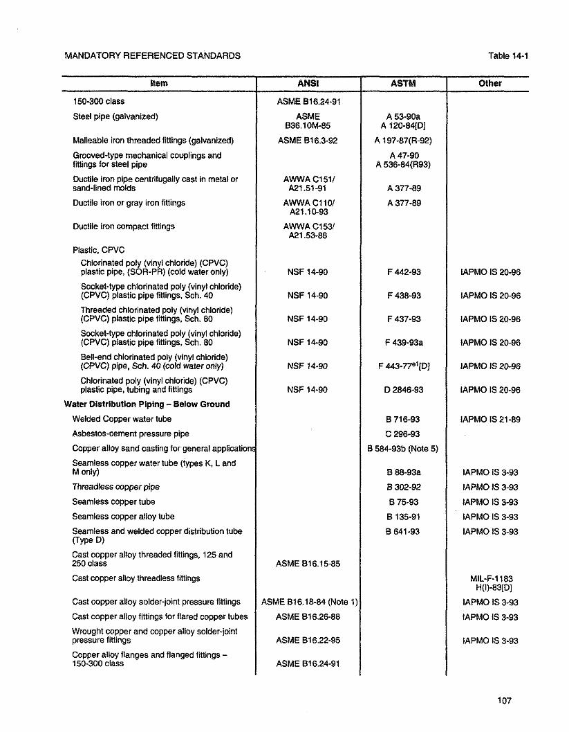
MANDATORYREFERENCEDSTANDARDS Table 14-1
Steel pipe (galvanized)
Malleable iron threaded fittings (galvanized) ASME 816.3-92
Grooved-type mechanical couplings and fittings for steel pipe
Ductile iron pipe centrifugally cast in metal or AWWA C1511 sand-lined molds
Ductile iron or gray iron fittings
Ductile iron compact fittings AWWA C1531
Plastic. CPVC Chlorinated poly (vinyl chloride) (CPVC) plastic pipe, (SOR-PR) (cold water only) NSF 14-90 IAPMO IS 20-96
Socket-type chlorinated poly (vinyl chloride) (CPVC) plastic pipe fittings. Sch. 40 IAPMO IS 20-96
Threaded chlorinated poly (vinyl chloride) (CPVC) plastic pipe fittings. Sch. 80 IAPMO IS 20-96
Socket-type chlorinated poly (vinyl chloride) (CPVC) plastic pipe fittings, Sch. 80 IAPMO IS 20-96
Bell-end chlorinated poiy (vinyl chloride) (CPVC) pipe, Sch. 40 (cold water only) IAPMO IS 20-96
Chlorinated poly (vinyl chloride) (CPVC) plastic pipe, tubing and fittings
Water Dlstributlon Piping - Below Ground
Welded Copper water tube
Asbestos-cement pressure pipe
Copper alloy sand casting for general applications
Seamless copper water tube (types K, L and M only)
Threadless copper pipe
Seamless copper tube
Seamless copper alloy tube
Seamless and welded copper distribution tube (Type D) Cast copper alloy threaded fittings, 125 and 250 class
Cast copper alloy threadless fittings
Cast copper alloy solder-joint pressure fittings
Cast copper alloy fittings for flared copper tubes
Wrought copper and copper alloy solder-joint pressure fittings
Copper alloy flanges and flanged fittings - 150-300 class
ASME 816.15-85
ASME 816.18-84 (Note 1)
ASME 816.26-88
ASME 816.22-95
ASME 816.24-91
B 71 6-93
C 296-93
B 584-93b (Note 5)
B 88-93a
B 302-92
B 75-93
B 135-91
B 641-93
IAPMO IS 20-96
IAPMO IS 21-89
IAPMO IS 3-93
IAPMO IS 3-93
IAPMO IS 3-93
IAPMO IS 3-93
IAPMO IS 3-93
MIL-F-1183 H(I)-83[D]
IAPMO IS 3-93
IAPMO IS 3-93
IAPMO IS 3-93

Table 14-1 UNIFORM PLUMBING CODE
Item
Steel pipe (galvanized)
Malleable iron threaded fittings (galvanized)
Ductile iron pipe centrifugally cast in metal or sand-lined molds
Ductile iron or grey iron fittings
Duclile iron compact fittings
Plastic, CPVC
Chlorinated poly (vinyl chioride) (CPVC) plastic pipe, Sch. 40 and 80 (cold water only)
Socket-type chlorinated poly(viny1 chloride) (CPVC) plastic pipe fittings, Sch. 40
Chlorinated poly (vinyl chloride) (CPVC) plastic pipe (SDR-PR) (cold water only)
Threaded chlorinated poly (vinyl chioride) (CPVC) plastic pipe fittings, Sch. 80 (cold water only)
Socket-type chlorinated poly (vinyl chloride) (CPVC) plastic pipe fittings, Sch. 80
Bell-end chlorinated poly (vinyl chloride) (CPVC) pipe, Sch. 40 (cold water only)
Chlorinated poly (vinyl chloride) (CPVC) plastic pipe, tubing and fittings hot and cold water
Plastic PEX
Crosslinked polyethylene (PEX) tubing
Crosslinked polyethylene (PEX) plastic hot- and cold-water distribution systems
Valves and Appurtenances
Angle, globe and check
Gate (bronze) steel flanged and butt welded
Corrosion-resistant cast flanged valves
Gate (cast iron bodies brass mounted)
Ball
Butterfly
Cocks, balancing, stop and check MSS standard marking system for valves, fittings. flanges and unions
Cast iron plug valves
Pressure reducing and regulating
Relief valves, pressure, temperature. temperaturelpressure
Thermostatic mixing valve
ANSI
ASME B36.10M-85
ASME 816.3-92
AWWAC1511 A21.51-91
AWWA C1101 A21 .lo-93
AWWA C1531 A21.53-88
NSF 14-90
NSF 14-90
NSF 14-90
NSF 14-90
NSF 14-90
NSF 14-90
NSF 14-90
ASME 816.34-88
AWWA C500-93
AWWA C504-88
ASSE 1003-95
221.22-a-90
ASSE 101 7-86
ASTM
A 53-93a A 120-84R
A 197-67(R-92)
A 377-89
A 377-89
F 441 -94
F 438-93
F 442-93
F 437-93
F 439-93a
F 443-77e1[D]
D 2846-93
F 876-93
F 877-93
Other
IAPMO IS 13-91
IAPMO IS 13-91
IAPMO IS 20-96
IAPMO IS 20-96
IAPMO IS 20-96
IAPMO IS 20-96
IAPMO IS 20-96
IAPMO IS 20-96
IAPMO IS 20-96
MSS-SP-71-90 MSS-SP-80-87
MSS-SP-42-90
MSS-SP-70-90
MSS-SP-72-92
MSS-SP.47-90
MSS-SP-25-93
MSS-SP-78-87

MANDATORYREFERENCEDSTANDARDS Table 14-1
Pre-Pressurized potable water tanks IAPMO PS 88-95
Unions
Carbon steel pipe unions MSS-SP-83-87
Malleable iron ASME 816.39-86
Copper alloy (bronze) WW-U-516A-74(b) WW-P-521 F-77
Flanges Cast iron ASME 816.1-89
Steel ASME 816.5-88 MSS-SP-44-91 ASME 81 6.47-90
Copper alloy flanges and flanged fiflingsl 50 lb. and 300 lb. ASME 816.24-91
Flared or compression connection non-ferrous pipe Ranges ASME 816.26-88
Copper alloy (bronze) ASME 816.24-91
Flanged gaskets ASME 816.21132
Backflow Preventers AWWA C510-92 AWWA C511-92 IAPMO PS 31-95
Pipe appl~ed atmospheric vacuum breakers ASSE 1001 -90
Hose-connected vacuum breakers ASSE 101 1-95
Hose connection backflow preventers ASSE 1052-93
Back siphonage vacuum breakers
Reduced pressure principle backflow preventer
Double check valve assembly
Pressure type vacuum breaker
Water hammer arrestors
Air gaps
Airgap units for water conditioning equipment installation
Trap primer valve (water distribution type)
Freezeless automatic draining and backflow wall hydrant
Dual check valve type backflow preventers for carbonated beverage dispensers-post mix types
Laboratory faucet vacuum breakers
JOINING MATERIAL AND METHODS - WATER SUPPLY SYSTEMS
Reinforced flexible water connectors
Tools for mechanically formed tee connections in copper tubing
Asbestos-cement pressure pipe
ASSE 1056-95
ASSE 1020-90
ASME A1 12.26.1M-84
ASME A1 12.1.2-91
ASSE 1018-86
A1 12.21.3M-85 (Note 1) ASSE 1019-95
ASSE 1035-95
C 296-93
ASSE 1013-93
ASSE 1015-93
ASSE 1010-82 PDI WH-201-92
IAPMO PS-23-89
IAPMO PS 65-93
ASSE 1032-80
IAPMO PS 74-95
IAPMO PS 85-95

Table 14-1 UNIFORM PLUMBING CODE
item I ANSI I ASTM I Other Rubber rings for asbestostement pipe D 1869-94
1 (
Rubber gasket joint for ductile iron and gray cast iron pressure pipe fittings A21.11-90 I AWWAC1ll' I Copper and nickel alloys (rods)
Brazing filler metals I AWS A5.8-92 I Grooved-type mechanical couplings and fittings I Grooved mechanical pipe couplings and grooved end fittings I I IAPMO PS 53-92
Dielectric waterway fittings
Solder metal
Lead-free sealing compounds for threaded joints
Making capillary joints by soldering of copper and copper alloy tube and fittings I
B 32-95a (Note 4)
Liquid and paste fluxes for soldering applications of copper and copper alloy tube I
IAPMO PS 66-93
IAPMO PS 36-90
Silver brazing joints for wrought and cast solder joint fittings I Caulking, lead wool and lead pig
Plastic, ABS
Solvent cement for Acrylonitrile Butadiene- Styrene (ABS) plastic pipe and fittings I NSF 14-90 I 02235-93a I Joints for plastic pressure pipes using flexible elastomeric seals
Plastic, cPVC
Solvent cements for chlorinated p l y (vinyl chloride) (CPVC) plastic pipe and fittings I
Plastic. PB
Metal insert fittings for polybutylene (PB) tubing
Joints for plastic pressure pipes using flexible elastorneric seals > Chlorinated poly (vinyl chloride) (CPVC) plastic pipe, tubing and fittings
Plastic, PE I I I Polyethylene (PE) piping
NSF 14-90
I IAPMO IS 7-90
Heatloining ply-olefin pipe and fittings
Flaring polyolefin pipe and tubing I
D 3139-89
D 2846-93
I D 2657-90
D 31 40-90 I IAPMO IS 7-90
IAPMO IS 20-96 NSF No. 14
IAPMO IS 20-96
Plastic insert fittings for polyethylene (PE) plastic pipe
Plastic, PVC
Solvent cement for poly (vinyl chloride) (PVC) plastic pipe and fittings I NSF 14-00 1 02564-93 I IAPMO IS 8-95
/
D 2609-93 (Note 1)
Primers for use in solvent cement joints of poly I ( ', (vinyl chloride) (PVC) plastic pipe and fittings NSF 14-90 F 656-93 IAPMO IS 8-95
>
IAPMO IS 7-90

MANDATORY REFERENCED STANDARDS Table 14-1
IAPMO IS 8-95
Making solvent-cemented joints with poly (vinyl chloride) (PVC) pipe and fittings IAPMO IS 8-95
Poly (vinyl chloride) (PVC) piping IAPMO IS 8-95
WRAPPING AND COATING
Protectively coated pipe (Installation) IAPMO IS 13-91
Black plastic poly (vinyl chloride) (PVC) or polyethyiene (PE) pressure-sensitive corrosion preventive tape IAPMO PS 37-90
AWWA C203-91
Footnotes > 2 PDI Standard G ~ O I by reference.
3 Additional Requirements for Inner and Outer Layers.
4 See Section 316.1.3 for restriction.
5 Alloy C85200 for cleanout plugs.
6 Limited to domestic sewage.
7 Type Il only.

ABBREVIATIONS IN TABLE 14-1
UNIFORM PLUMBING CODE
AH AM
ANSI
ASME
ASSE
ASTM
AWS
AWWA
CAB0
cIsm (D) or ID1 el
MSS
NEMA
NFPA
NSF
PDI
SSPMA
UL
Association of Home Appliance Manufacturers, 20 North Wacker Drive, Chicago, IL 60606.
American National Standards Institute, Inc., 11 W. 42nd Street, 13th floor, New York, NY 10036.
The American Society of Mechanical Engineering, 345 East 47th Street, New York, NY 10017.
American Sdiety of Sanitary Engineering, P.O. Box 40362, Bay Village, OH 44140.
American Society of Testing and Materials, 100 Barr Harbor Drive, West Conshohocken, PA 19428-2959.
American Welding Society, 550 NW LeJuene Road, Miami, FL 33126.
American Water Works Association, 6666 W. Quincy Avenue, Denver, CO 80235.
Council of American Building Officials, 5203 Leesburg Pike, Suite 708, Falls Church, VA 22041.
Cast Iron Soil Pipe Institute, 5959 Shallowford Road, Suite 419, Chattanooga, TN 37421.
Discontinued.
An editorial change since the last revision or reapproval.
Federal Specifications, Federal Supply Service, Standards Division, General Services Administration, 7th and D Streets, Washington, lX 20407.
International Association of Plumbing and Mechanical Officials, 20001 Walnut Drive S., Walnut, CA 91789-2825.
Manufacturers Standardization Society of the Valve and Fittings Industry, 127 Park Street, N.E., Vienna, VA 22180.
National Electrical Manufacturers Association, 2101 L Street, N.W., Suite 300, Washington, lX 20037.
National Fire Protection Association, P.O. Box 9101,l Batterymarch Park, Quincy, MA 02269-9101.
NSF International, 3475 Plymouth Road, P.O. Box 1468, Ann Arbor, Mi 48106.
Plumbing aid Drainage Institute, 1106 W. 77th Street, South Drive, Indianapolis, IN 46208.
Sump and Sewage Pump Manufacturers Association, P.O. Box 298, Winnetka, IL 60093-0298.
Underwriters' Laboratories, Inc., 333 Pfingsten Road, Northbrook, IL 60062.

MANDATORYREFERENCEDSTANDARDS
TABLE 14-2
Fixture and Fitting Standards
Air gaps. dishwasher drain ............................................................................... ANSllAHAM DW.1. ASSE 1021 Bathtubs. enameled cast-iron ..................................................................................... ANSIIASME A1 12.19.1 M Bathtubs. enameled steel ........................................................................................... ANSIIASME A1 12.19.4M Bathtubs, plastic ............................................................................................................................. ANSI 2124.1 Bathtub fixture fittings ................................................................................................. ANSIIASME A1 12.18.1M Bidets, vitreous china ..................................................................................................... ANSIIASME A1 12.19.2 Ballcocks, water closet flush tank ..................................................................................... ANSIIASSE 1002 Clothes washers, domestic. automatic ......................................... ANSIIAHAM HLW-2PR or ANSIIASSE 1007 Dishwashers. commercial ..................................................... ANSIIUL 923 and ANSNASSE 1004 . NSF 3-82 Dishwashers, domestic ............................ ANSllUL 749 and either ANSIIAHAM DW-2PR or ANSIIASSE 1006 Diverters, anti-siphon faucets ................................................................................................. ANSIIASSE 1025 Drinking fountains. refrigerated ................................................................. ANSIIARI 1010 and ANSllUL 399 Floor drains ............................................................................................................................ ANSI A1 12.21.1 M Flushometer valves ................................................................................................................. ANSIIASSE 1037 Food-waste-grinder units .......................... ANSllUL 430 and AHAM FWD.1, ASSE 1008, or ANSIIASSE 1008 . . > Hydrants, utlllty ......................................................................................................... ANSIIASME A1 12.21.3M Lavatories, vitreous china .......................................................................................... ANSIIASME A1 12.19.2M Lavatories, enameled steel ......................................................................................... ANSVASME A1 12.1 9.4M Lavatories, enameled cast-iron .............................................................................. ANSIIASME A1 12.19.1 M Lavatories. stainless steel ........................................................................................... ANSIIASME A112.19.3M Lavatories. plastic .......................................................................................................................... ANSI 2124.3 Lavatories, ceramic. non-vitreous .............................................................................. ANSIIASME A1 12.19.9M Lavatory fixture fittings .............................................................................................. ANSIIASME A1 12.1 8.1M Roof drains ............................................................................................................................ ANSIlA112.21.2M Shower heads and control valves ...................................... ANSIIASME A1 12.18.1 M, ASSE 1016, ASSE 1017 Shower devices, hand.held, water-connected ...................................................................... ANSIIASSE 1014 Showers. plastic ............................................................................................................................ ANSI 2124.2 Sinks. enameled cast-iron .......................................................................................... ANSIlASME.Al12.19.1 M Sinks, enameled steel ................................................................................................. ANSIIASME A1 12.1 9.4M Sinks, stainless steel ................................................................................................... ANSIIASME A1 12.19.3M Sink fixture fittings ............................................................................................... ANSIIASME A1 12.18.1M Urinals. plastic ................................................................................................................................ ANSI 2124.9 Urinals. vitreous china ............................................................................................................. ANSI A1 12.9.2M Urinals, hydraulic requirements ............................... ......... ............................................. ANSIIASME A1 12.19.6 Wall hydrants, anti.freeze. with vacuum breaker .......................................................................... ASSE 1019 Water closets, vitreous china .................................................................................................. ANSI A1 12.19.2M Water closets, plastic ..................................................................................................................... ANSI 2124.4 Water closets, hydraulic requirements ........................................................................... ANSIIASME A1 12.19.6 Water closet seats ..................................... ... .................................................................................. ANSI 2124.5 Water closet trim ..................................................................................................................... ASME A1 12.19.5 Water coolers, refrigerated ............................................................................ ANSIIARI 101 0 and ANSllUL 399 Water flow control devices ..................... .. ................................................................ ASSE 1028, ASSE 1034 > Whirlpool baths, plastic ........................................................................................ ANSIIASME A1 12.19.7M Whirlpool baths, suction fitting ......................................................... ANSIIASME A1 12.19.8M, IAPMO SPS4 Whirlpool bath fixture fittings ................................ ........ .......................................... ANSIIASME A1 12.18.1M

UNIFORM PLUMBING CODE

APPENDICES
The appendices are intended to supplement the provisions of the installation requirements of this Code. The definitions in Chapter 2 are also applicable to the appendices.
TABLE OF CONTENTS
Page Appendix A
Recommended Rules for Sizing the Water Supply System ............................................................... 117
Appendix B Explanatory Notes on Combination Waste and Vent Systems .......................................................... 119
Appendix C Additional Referenced Standards ....................................................................................................... 121
Appendix D Sizing Stormwater Drainage Systems ............................................................................................. 123
Appendix E ManufacturedIMobile Home Parks and Recreational Vehicle Parks .................................................. 131
Appendix F Resewed
Appendix G Graywater Systems for Single Family Dwellings ................................................................................ 133
Appendix H Recommended Procedures for Design, Construction and lnstallation of Commercial Kitchen Grease Interceptors ............................................................................................................ 135
Appendix I Installation Standards ......................................................................................................................... 137
Appendix J Reclaimed Water Systems for Non-Residential Buildings ......................... .. ..................................... 139
Appendix K Private Sewage Disposal Systems ................................................................................................... 141
Appendix L
Alternate Plumbing Systems .............................................................................................................. 143

UNIFORM PLUMBING CODE

APPENDIX A
RECOMMENDED RULES FOR SIZING THE WATER SUPPLY SYSTEM
> <Appendix A is not adopted by the State of Indiana.)

UNIFORM PLUMBING CODE

APPENDIX B
EXPLANATORY NOTES ON COMBINATION WASTE AND VENT SYSTEMS (See Section 91 0.0 for specific limitations.)
> <Appendix B is not adopted by the State of Indiana.)

UNIFORM PLUMBING CODE

APPENDIX C
ADDITIONAL REFERENCED STANDARDS
> <Appendix Cis not adopted by the State of Indiana.)

UNIFORM PLUMBING CODE

APPENDIX D SIZING STORMWATER DRAINAGE SYSTEMS
11 Appendix D is adopted by the State of Indiana. D 1 Roof Drainage The rainfall rates in Table D-1 should be used for design unless higher values are established locally.
TABLE D-1 Maximum Rates of Rainfall for Various Cities
The rainfall rates in this table are based on U.S. Weather Bureau Technical Paper No. 40, Chart 14: 100-Year 60-Minute Rainfall (inches).
States and Cities
ALABAMA Birmingham Huntsville Mobile Montgomery
ALASKA Aleutian Islands Anchorage Bethel Fairbanks Juneau
ARIZONA Flagstaff Phoenix Tucson
ARKANSAS Eudora Ft. Smith Jonesboro Little Rock
CALIFORNIA Eureka Lake Tahoe Los Angeies Lucerne Valley Needles Palmdale Redding San Diego San Francisco San Luis Obispo
Storm Drainage 60-Minute Duration,
IncheslHour
3.7 3.3 4.5 3.8
1 .O 0.6 0.8 1 .O 0.6
2.3 2.2 3.0
3.8 3.9 3.5 3.7
1.5 1.3 2.0 2.5 1.5 3.0 1.5 1.5 1.5 1.5
100-Year Return
GPMlSquare Foot
0.038 0.034 0.047 0.039
0.010 0.006 0.008 0.010 0.006
0.024 0.023 0.031
0.039 0.041 0.036 0.038
0.016 0.014 0.021 0.026 0.016 0.031 0.01 6 0.016 0.016 0.016

A
Appendix D UNIFORM PLUMBING CODE
TABLE D-1 (Continued) Maximum Rates of Rainfall for Various Cities
124
States and Cities
COLORADO Craig Denver Durango Stratton
CONNECTICUT Hatiford New Haven
DELAWARE Dover Rehobeth Beach
DISTRICT OF COLUMBIA Washington
FLORIDA Daytona Beach Ft. Myers Jacksonville Melbourne Miami Palm Beach Tampa Talahassee
GEORGIA Atlanta Brunswick Macon Savannah Thomasvilie
HAWAII
Storm Drainage 60-Minute Duration,
InchesMour
1.5 2.2 1.8 3.0
2.8 3.0
3.5 3.6
4.0
4.0 4.0 4.3 4.0 4.5 5.0 4.2 4.1
3.5 4.0 3.7 4.0 4.0
Rainfall rates in the Hawaiian Islands vary from 1-112 incheslhour to 8 incheslhour, depending on location and elevation. Consult local data.
100-Year Return
GPMISquare Foot
0.016 0.023 0.019 0.031
0.029 0.031
0.036 0.037
0.042
0.042 0.042 0.045 0.042 0.047 0.052 0.044 0.043
0.036 0.042 0.038 0.042 0.042
IDAHO Boise Idaho Falls Lewiston Twin Falls
ILLINOIS Chicago Harrisburg Peoria Springfield
1 .O 1.2 1 .O 1.1
2.7 3.1 2.9 3.0
0.010 0.012 0.010 0.01 1
0.028 0.032 0.030 0.031

SIZING STORMWATER DRAINAGE SYSTEMS Appendix D
Maximum
States and Cities
INDIANA Evansville Indianapolis Richmond South Bend
IOWA Council Bluffs Davenport Des Moines Sioux City
KANSAS Goodland Salina Topeka Wichita
KENTUCKY Bowling Green Lexington Louisville Paducah
LOUISIANA Monroe New Orleans Shreveport
MAINE Bangor Kittery Millinocket
MARYLAND Baltimore Frostburg Ocean City
MASSACHUSETTS Adams Boston Springfield
MICHIGAN Detroit Grand Rapids Kaiamazoo Sheboygan Traverse City
TABLE Dl (Continued) Rates of Rainfall for Various Cities
Storm 60-Minute Duration,
lnchedliour
3.0 2.8 2.7 2.7
3.7 3.0 3.4 3.6
3.5 3.8 3.8 3.9
2.9 2.9 2.8 3.0
3.8 4.5 4.0
2.2 2.4 2.0
3.6 2.9 3.7
2.6 2.7 2.7
2.5 2.6 2.7 2.1 2.2
Drainage 100-Year Return
GPMlSquare Foot
0.031 0.029 0.028 0.028
0.038 0.031 0.035 0.037
0.036 0.039 0.039 0.041
0.030 0.030 0.029 0.031
0.039 0.047 0.042
0.023 0.025 0.021
0.037 0.030 0.038
0.027 0.028 0.028
0.026 0.027 0.028 0.022 0.023

Appendix D UNIFORM PLUMBING CODE
TABLE D-1 (Contlnued) Maximum Rates of Rainfall for Various Cities
States and Cities
MINNESOTA Duluth Grand Forks Minneapolis Worthington
MISSISSIPPI Biloxi Columbus Jackson
MlSSOURl Independence Jefferson City St. Louis Springfield
MONTANA Billings Glendive Great Falls Missoula
NEBRASKA Omaha North Plane scons B IU~
NEVADA Las Vegas Reno Winnemucca
NEW HAMPSHIRE Berlin Manchester
NEW JERSEY Atlantic City Paterson Trenton
NEW MEXICO Albuquerque Carlsbad GaHup
NEW YORK Binghamton Buffalo New York Schenectady Syracuse
Storm 60-Minute Duration,
InchesMour
2.6 2.5 3.0 3.4
4.5 3.5 3.8
3.7 3.4 3.2 3.7
1.8 2.5 1.8 1.3
3.6 3.5 2.8
1.5 1.2 1 .O
2.2 2.5
3.4 3.0 3.2
2.0 2.6 2.1
2.4 2.3 3.1 2.5 2.4
Drainage 100-Year Return
GPMISquare Foot
0.027 0.026 0.031 0.035
0.047 0.036 0.039
0.038 0.035 0.033 0.038
0.019 0.026 0.019 0.014
0.037 0.036 0.029
0.016 0.01 2 0.010
0.023 0.026
0.035 0.031 0.033
0.021 0.027 0.022
0.025 0.024 0.032 0.026 0.025 -

SIZING STORMWATER DRAINAGE SYSTEMS
NORTH CAROLINA Ashville Charlotte Raleigh Wilmington
TABLE Dl (Continued) Maximum Rates of Rainfall for Various Cities
NORTH DAKOTA Bismarck Fargo Minot
States and Cities
OHIO Cincinnati Cleveland Columbus Toledo Youngstown
OKLAHOMA Boise City Muskogee Oklahoma City
Storm Drainage 60-Minute Duration, 100-Year Return
OREGON Medford Portland Ontario
Inches/Hour
PENNSYLVANIA Erie Harrisburg Philadelphia Pittsburgh Scranton
OPMlSauare Foot
RHODE ISLAND Newport Providence
SOUTH CAROLINA Charleston Columbia Greenville
SOUTH DAKOTA Lemmon Rapid City Sioux Fails

Appendix D UNIFORM PLUMBING CODE
Maximum
S?at;stes and Cities
TENNESSEE Knoxville Memphis Nashville
TEXAS Corpus Christi Dallas El Paso Houston Lubbock San Antonio
UTAH Bluff Cedar City Salt Lake City
VERMONT Bennington Burlington Rutland
VlRGlNlA Charlottesville Richmond Roanoke Norfolk
WASHINGTON Seattle Spokane Walla Walla
WEST VIRGINIA Charleston Martinsburg Morgantown
WISCONSIN La Cross Green Bay Milwaukee Wausau
WYOMING Casper Cheyenne Evaston Rock Springs
TABLE P 1 (Continued) Rates of Rainfall for Various Cities
Storm 60-Minute Duration,
Inches/Hour
3.1 3.5 3.0
4.6 4.2 2.0 4.6 3.3 4.4
2.0 1.5 1.3
2.5 2.3 2.4
3.4 4.0 3.3 4.0
1 .O 1 .O 1 .O
2.9 3.0 2.7
2.9 2.5 2.7 2.5
1.9 2.5 1.3 1.4
Drainage 100-Year Return
GPMlSquare Foot
0.032 0.036 0.031
0.048 0.044 0.021 0.048 0.034 0.046
0.021 0.016 0.014
0.026 0.024 0.025
0.035 0.042 0.0M 0.042
0.01 0 0.010 0.010
0.030 0.031 0.028
0.030 0.026 0.028 0.026
0.020 0.026 0.014 0.015

SIZING STORMWATER DRAINAGE SYSTEMS Appendix D
D 2 Siting by Flow Rate Storm drainage systems can be sized by stormwater flow rates, using the appropriate GPM/square foot of rainfall listed in Table D-1 for the local area. Multiplying the listed GPM/square foot by the roof area being drained by each inlet (in square feet), produces the gallons per minute (GPM) of required flow for sizing each drain inlet. The flow rates (GPM) can then be added to determine the flows in each section of the drainage system. Required pipe sizes for various flow rates (GPM) are listed in Table 11-1 and Table 11-2.
D 3 Siting by Roof Area Storm drainage systems can be sized using the roof area sewed by each section of the drainage system. Maximum allowable roof areas with various rainfall rates are listed in Table 11-1 and Table 11-2, along
with the required pipe sizes. Using this method, it may be necessary to interpolate between two listed rainfall rate columns (inches per hour). To determine the allowable roof area for a listed size pipe at a listed slope, divide the allowable square feet of roof for a one (I) inch (25.4 mm/hr) rainfall rate by the listed rainfall rate for the local area. For example, the allowable roof area for a six (6) inch (152 mm) drain at one-eighth (1/8) inch (3.2 mm) slope with a rainfall rate of 3.2 inches (81 mm/hr) is 21,400/3.2 = 6688 (621.3m2) square feet.
D 4 Capacity of Rectangular Scuppers Table D-2 lists the discharge capacity of various width rectangular roof scuppers with various heads of water. The maximum allowable level of water on the roof should be obtained from the structural engineer, based on the design of the roof.
TABLE D-2 Discharge from Rectangular Scuppers - Gallons per Minute
Water Head, inches
112 1
1.112 2
2-112 3
3-1 12 4
Width of Scupper In Inches 6 12 18 24 30
6 13 19 25 32 17 35 53 71 89 31 64 97 130 163
98 149 200 251 136 207 278 349 177 271 364 458
339 457 575 412 556 700
TABLE D-2 (Metric) Discharge from Rectangular Scuppers -Liters per Second
Water Head (mm) 152
13 0.4 25 1.1 38 2.0 51 64 76 89
102
Nntea!
Width of Scupper in Millimeters 305 457 610 762
0.8 1.2 1.6 2.0 2.2 3.3 4.5 5.6 4.0 6.1 8.2 10.3 6.2 9.4 12.6 15.8 8.6 13.1 17.5 22.0
11.2 17.1 23.0 28.9 21.4 28.8 36.3 26.0 35.1 44.2
. . - -- - . 1. Table D-2 is based on discharge over a rectangular weir with end contractions. 2. Head is the deoth of water above bonom of the scuooer ooenino. 3. The height of the scupper opening should be at leakitwo i2) links the design head. 4. Coordinate the allowable head of water with the structural design of the roof.

UNIFORM PLUMBING CODE

APPENDIX E
MANUFACTUREDlMOBlLE HOME PARKS AND RECREATIONAL VEHICLE PARKS
> <Appendix E is not adopted by the State of Indiana.)

UNIFORM PLUMBING CODE

APPENDIX G
GRAYWATER SYSTEMS FOR SINGLE FAMILY DWELLINGS
> <Appendix G is not adopted by the State of Indiana.)

UNIFORM PLUMBING CODE

APPENDIX # RECOMMENDED PROCEDURES FOR DESIGN, CONSTRUCTION
AND INSTALLATION OF COMMERCIAL KITCHEN GREASE INTERCEPTORS
> <Appendix H is not adopted by the State of Indiana.)

UNIFORM PLUMBING CODE

APPENDIX I
INSTALLATlON STANDARDS
> <Appendix I is not adopted by the State of Indiana.)

UNIFORM PLUMBING CODE

APPENDIX J RECLAIMED WATER SYSTEMS FOR NON-RESIDENTIAL BUlLDlNGS
> <Appendix J is not adopted by the State of Indiana.)

UNIFORM PLUMBING CODE

APPENDIX I<
PRIVATE SEWAGE DISPOSAL SYSTEMS
> <Appendix K is not adopted by the State of Indiana.)

UNIFORM PLUMBING CODE

APPENDIX L ALTERNATE PLUMBING SYSTEMS
> <Appendix L is not adopted by the State of Indiana.)
11 See the General Administrative Rules 675 IAC 12-6-11, for alternate plumbing systems.

UNIFORM PLUMBING CODE

INDIANA PLUMBING CODE 1999 Edition
RULE 2 AMERICAN SOCIETY OF SANITARY ENGINEERS STANDARD 1051-1998
Title; availability
Sec. 1. (a) This rule shall be published, except for incorporated documents, by the Fire and Building Services Department, for general distribution and use under that title.
(b) The American Society of Sanitary Engineers Standard 1051 is available for purchase from the Fire and Building Services Department, Indiana Government Center-South, 402 West Washington Street, Room W221, Indianapolis, Indiana 46204-2739.
Adoption by reference
Sec. 2. That certain document, being titled as American Society of Sanitary Engineers Standard 1051,1998 Edition, published by the American Society of Sanitary Engineers, 28901 Clemens Road, Westlake, Ohio 44145, be and the same is hereby adopted by reference, as if fully set out in this rule, save and except those amendments made in this rule.
Connections
Sec. 3. Delete subsection 1.4.7 without substitution.
Code requirements; definitions
Sec. 4. (a) Change section 4.1.6, code requirements to read as follows: Installation shall be in accordance with the manufacturer's installation instructions, and the plumbing code.
(b) Delete the first sentence of section 5.0. Definitions.


- A . Abandoned cesspools. grease interceptors .
septic tanks. and seepage pits ....................................... L O Appendix K Absorption area. capacity of ........................................................... Table K-4. Appendix K Access panels .................................................................................... 203.0. 405.0. 415.0 . . Accessible. defin~t~on ................................................................................................... 203.0 Accessibility of:
Backwater valves ................................................................................... 710.0. 1006.0 Bushings. gas .................................................................................................... 121 1.0 Chemical waste system ........................................................................................ 81 1.0 Cleanouts ................................................................................................. 707.0. 71 9.0 Fixtures for inspection. repairs. and cleaning ...................................................... 408.0 Floor drain traps ................................................................................................ 1006.0 Gas meters ...................................................................................................... 1209.0 Grease traps or interceptors ............................................. 1009.0. 1014.0. Appendix H Industrial interceptors and separators ............................................................... 1009.0 Receptors ............................................................................................................ 804.0 Regulator and relief valves .................................................................................. 608.0 Septic tanks ............................................................................................... Appendix K Shutoff and control valves ...................................................................... 605.0. 121 1.0 Slip joints ............................................................................................................. 405.0 Sump and receiving tanks .................................................................................. 810.0 Valves. gas ........................................................................................................ 121 1.0 Valves. water ...................................................................................................... 605.0 Water heaters ........................................................................................... 507.0. 51 1.0
Acrylonitrile-Butadiene-Styrene (ABS) ...................................... 203.0. 701 .O. 707.1. 903.0 Additions ................................................................................................... 101.4.1.1, 301.0 Additives . packing. prohibited ................................................................................ 705.1.5 Administrative Authority. definition .............................................................................. 203.0 Advance notice for inspections ...................................................................... 103.5.4.1 Airbreak:
Definition ............................................................................................................. 203.0 Required ................... : .......................................................................................... 8 0 . 0
Airgap: Definition ............................................................................................................. 203.0 Required ............................................................................. 603.3. 801.1. 806.0. 807.0
Air intakes. vent termination near .............................................................................. 906.0 Air tank. for sumps ...................................................................................................... 710.0 Air tests:
Gas piping system ............................................................................................. 1214.0 Water piping system .................................................................................... 103.5.3.3
Alterations and repairs: Deviations allowed ............................................................................. 101.4.1.1. 301.0 Gas piping .............................................................................................. 301.0. 1210.0 Sewage disposal .............................................................................................. 301.0 Water heaters .................................................................................................... 301.0 Water piping ....................................................................................... 101.4.1 .l. 301.0
Alternate materials ........................................................................................... 301 .O. 403.0 Anchors and hangers; see "Supports" Appliance:
Connectors ................................................................. 1212.0. Tables 12-9 & 12-10 Gas. demand requirements ............................................................ 1216.0. Table 12-1 Indirect waste type .................................................................................... 806.0.808.0
Application for Permit ................................................................................................... 303.2

UNIFORM PLUMBING CODE
Approval Required: Appliances. fixtures ................................................. 301 .O. 407.0. 505.0. 506.0. 610.0 Backflow preventers ............................................................................................ 603.0 Ballcocks .......................................................................................................... 603.4.2 Cesspool .................................................................................................... Appendix K Chemical waste system ........................................................................................ 811.0 Combination waste and vent system ............................................. 910.0. Appendix B Completed plumbing work .................................................................................. 103.5 Devices ................................................................................................................ 603.0 Flue, vents ........................................................................................................... 512.0 Grease trap ................................................................................................ 101 1.0 Indirect waste receptors ..................................................................................... 602.0 Industrial interceptors and separators ............................................................. 1009.0 Materials. specifications, standards ....................................................... 301 .O, 707.0 Plans ...................................................................................................... 101.3, 1014.0 Seepage pit ................................................................................................ Appendix K Septic tank and disposal system ................................................................ Appendix K Special fixtures .................................................................................................... 407.0 Vacuum breakers ................................................................................................ 603.0 Water heaters, gas .............................................................................................. 505.0 Water heaters, oil ................................................................................................ 506.0 . .
Approved, general definct~on ........ : .............................................................................. 203.0 . . Approved. gas code defin~tcon .................................................................................. 1202.0 Approved testing agency .............................................. 203.0, 301 .O, 502.0, 609.6, 1202.0 Area Drain, definition .................................................................................................. 203.0 Aspirator, definition ..................................................................................................... 203.0 Asbestos cement pipe joint ...................................................................................... 705.1.4 Aspirators, protection .................................................................................................. 603.0 Attachment, vertical piping ......................................................................................... 314.0 Attic installation, water heaters ................................................................................... 51 1.0 Authority to:
Disconnect gas .................................................................................................. 1207.0 Render gas service .......................................................................................... 1206.0
Automatic: Clotheswasher stand pipe ................................................................................... 804.0 Flushing tanks ..................................................................................................... 409.0 Flush valves ........................................................................................................ 409.0 Priming device. for floor drains ........................................................................ 1007.0 Siphon, septic tank ..................................................................................... Appendix K
Auto wash racks ....................................................................................................... 101 1.0
-8- Backfilling ................................................................................................................... 315.0 Backflow ............................................................................................. 204.0, 603.0. 1002.0 Backflow connection ........................................................................................ 204.0, 603.0 Backflow preventer; see "Cross-Connections: "Back Siphonage" Backing for fixtures ..................................................................................................... 408.0 Backpressure backflow ...................................................................................... 2040, 603.0 Back siphonage; see "Cross-Connections: "Backflow Preventer" Back siphonage of traps, protection ......................................................................... 1002.0 Back to back fixtures .................................................................................................. 704.0 Backwater valve ............................................................................................. 204.0. 710.0 Ballcocks, approval required ......................................... .......................... .......... 603.0 Baptistries ................................................................................................................... 407.0 Bathtub, prohibited type .............................................................................................. 406.0 Bell and spigot joints ................................................................................................... 705.1

INDEX
Bell traps. prohibited ................................................................................................. 1004.0 Benching of trenches ...................................................................................... 315.0. 720.0 Blow off condensers ................................................................................................... 810.0 Boiler blowoff:
Definition .............................................................................................................. 204.0 Prohibited discharge ............................................................................................. 810.0
Boiler, hot water .......................................................................................................... 505.0 Boiler, steam ............................................................................................................... 505.0 Bolts, non-corrosive .................................................................................................... 408.0 Bowl wax or gaskets ................................................................................................... 316.3 . . Branch, definltron ........................................................................................................ 204.0 Branch, fixture, definition ......................................................................................... 204.0 . . Branch, horizontal, definttron ...................................................................................... 204.0 . . Branch vent, defin~tton .............................................................................................. 204.0 Brass connections, ground joint .............................................................................. 705.4.3 Brass pipe ................................................................................ 701.0, 604.0, 903.0, 1210.0 Brazing or welding joints ............................................................................... 310.0. 316.1.6 Btu rating, gas appliances ........................................................................................ 1216.0 Building. definition ........................................................................................................ 204.0 Building drain (sanitary)
Definition .............................................................................................................. 204.0 Size of ................................................................................................................. 703.0
Building drain (Storm), definition ................................................................................. 204.0 Buildings over sewer ............................................................................................ 101.4.1.1 Building sewer ..................................................................................................... Chapter 7
Cleanouts ............................................................................................................ 719.0 . . Combined. definttron ........................................................................................... 204.0 Damage to ........................................................................................................... 306.0 Definition ............................................................................................................... 204.0 Distance from building and below ground ................................................ 313.0, 607.0 Grade and support of ............................................. ........................................... 607.0 Location of ........................................................ 308.0. 313.0, 718.0. 721.0, Table 7-7 Material of ........................................................................................ 715.0, Table 14-1 Must be on same lot as buildings ....................................................................... 308.0 Required ................................................................................................... 305.0, 713.0 . . Sanitary, definrtlon ............................................................................................... 204.0 Size of .................................................................................................................. 717.0 Storm, definition .................................................................................................. 204.0 Testing of ............................................................................................................. 723.0 Water pipe in trench ............................................................................................ 720.0
Building sewers and drains. existing .................................................................... 101.4.1.1 . . Building subdrain, definition ........................................................................................ 204.0
Building supply, definition ........................................................................................... 204.0 Burned lead joints .................................................................................................... 705.1.3 Burred ends ................................................................... 310.3. 609.0, 701.0, 903.0, 1210.0 Bushings, concealed gas ........................................................................................ 121 1.10 Bushings, solder ..................................................................................... 701.4.2. Table 7-2
- C - Capacity of:
Disposal field .............................................................................................. Appendix K Seepage pits ............................................................................................. Appendix K Water closet tanks ............................................................................................... 402.0
Cast iron soil pipe and fittings Joints and connections ..................................................................................... 705.3.2 Support of ............................................................................................................ 314.0

UNIFORM PLUMBING CODE
Caulked joints ............................................................................................................. 705.1 Caulking. waterproofing .............................................................................................. 408.0 Caulking ferrules ..................................................................... 701.4. 705.3.4. Table 7-1 Cement mortar joints. prohibited ............................................................................. 705.1.2 Certificate of Final Approval ........................................................................... 103.5. 1205.0 Certification of:
Backflow assembly testers ...................................................................... 205.0. 603.3.2 Medical gas certifiers .......................................................................................... 1303.3 Medical gas installers ......................................................................................... 1303.3 Medicalgas systems .......................................................................................... 1303.2 Pipe welder ............................................................................................... 205.0. 121 1.2
Cesspool: .......................................................................................................... Appendix K Abandoned .......................................................................................................... 722.0 Connections to sewer prohibited ......................................................................... 714.0 Definition ............................................................................................................. 205.0 Distance from lot line. building. surface ................................................ 402.0. Table 7-7 Must be on same lot as building ......................................................................... 308.0
Change in direction of drainage piping ....................................................................... 706.0 Change in direction of gas piping ........................................................................... 121 1.17 Check valves:
In gas systems ................................................................................................ 1211.1 1 In water systems ................................................................................................. 608.3
Chemical toilet. prohibited .......................................................................................... 406.2 Chemical wastes .................................................................................. 205.0. 81 1.0. 81 1.2 Clinic sink. definition ................................................................................................... 205.0 Clarifier ......................................................................... 205.0. 1008.0~1013.0. Appendix H . . Clay. vitnf~ed ............................................................................................................... 701.0
Joints and connections ..................................................................................... 705.3.1 Cleanout plugs or caps ............................................... 707.1. 707.2. 707.3 707.13. 707.14. Cleanouts .......................................................................................................... 707.0. 719.0 Clearance for:
Water heaters ................................................................................ 507.0. 508.0. 51 1.0 Water heater vents .............................................................................................. 512.0
Clear water waste. definition ...................................................................................... 205.0 Closet bends. prohibited type ................................................................................... 31 1.0
Maximum length ................................................................................................ 1002.0 Permitted ............................................................................................................. 316.2
Closet rings ............................................................................. 316.3. 316.3.2, 704.0. 704.4 Closet screw bolts ...................................................................................................... 704.5 Clothes washer stand pipe ......................................................................................... 804.0 Code:
Defi.nition ............................................................................................................. 205.0 Validity of ............................................................................................................ 103.8
Combination fixture ................................................................................................... 1001.0 Combination waste and vent system ........................................... 205.0. 910.0. Appendix B Combustible construction, definition ............................................................................. 205.0 Combustible material, definition .............. ; ....... .; .......................................................... 502.0 Combustion air. required ............................................................................................ 507.0 Common ........................................................................................................... 205.0. 905.0 Common vent. gas ..................................................................................................... 519.0 Compartments for:
Toilets .................................................................................................................. 408.0 Water heaters ...................................................................................................... 507.0
Compression joints .................................................................................................. 316.1.4 Concealed slip joints .................................. .: ............................................................... 405.1 Concealing of work prohibited before inspection .................... 103.5.1.1. 103.5.1.3. 1204.0

INDEX
Condensers and sumps .............................................................................................. 810.0 Control, shutoff valves ................................................................................ 605.0, 1211.0 Connection:
At septic tank ............................................................................................. Appendix K Indirect waste piping ........................................................................................... 603.0 To plumbing system. required ............................................................................. 304.0 To sewer, required ................................................................................... 305.0, 713.0
Connector, vent .............................................................. 502.0, 515.0, 516.0, 519.0, 520.0 Connector, gas ....................................................................... Tables 12-9, 12-1 0 & 12-1 4 Construction . existing .......................................................................................... 101.4.1.3 Contamination ............................................................................................ 2050, Table 6-2 Continuous vent, definition ......................................................................................... 205.0 Continuous waste:
Definition ............................................................................................................. 205.0 Materials ......................................................................................................... 405.0 Multiple fixtures ................................................................................................. 1001.0
Cooling units: Drains .................................................................................................................. 801.0 Potable water waste pipes ................................................................................ 808.0
Cooling water, connection permitted .......................................................................... 808.0 Copper and lead pans ................................................................................................ 410.5 Copper pipe or tubing:
Connection to screwed pipe .......................................................................... 316.2.1 Fittings for ....................................................................... 604.0, 701.0, 903.0. 1210.0 Forming .............................................................................................................. 609.1 Joints and connections ..................................................................................... 606.2.1 Location and use of .......................................... 604.0, 604.2. 701.1.4-5. 81 1.1, 903.0 Marking of ............................................................................................................ 604.3 Quality and weight of material ................................................. 604.2, 604.4, 701.1.4.5
......................................................................................................... Suppolt of 314.0 Corrections. inspection ..................................................................................... 103.5.6.1.2 Corrosion, protection from ............................................................... 313.5. 609.3.1, 121 1.5 Cover plate .................................................................................................. 707.9, 710.1 0 Critical level .................................................................................................. 205.0. 603.4.5 Cross-connections: see "Backflow, " "Back Siphonage"
Approval of preventive devices .............................................................. 601 .0.60 3.0 Backflow preventers .................................................................................. 602.0-603.0 Control ...................................................................................................... 601 .O-60 3.0 Critical level ...................................................................................................... 603.4.5 Definition ............................................................................................................... 205.0 Prohibited ............................................................................ 407.1. 408.5, 601.0.603.0 Vacuum breakers ............................................................................................ 603.1.4
Cutting of structural members .................................................................................... 313.2
. D . Damage to drainage and sewer systems ........................................................ 306.0. 714.0 Damper. gas vents. prohibited .................................................................................... 513.0 Dangerous or insanitary plumbing ........................................................................... 101.5.2 Defective material. gas ............................................................................................. 1214.0 Defective systems. testing of ..................................... .... ....................................... 103.5.5.1 Definition of terms ....................................................................... Chapter 2. 502.0. 1202.0 . . Dead end. defin~tion .................................................................................................. 206.0 Demand. gas appliance ........................................................................................... 1216.0 Department Having Jurisdiction. definition .................................... .... .................... 206.0 Detrimental wastes .............................................................. : ...................... 307.0. 1009.0 Developed length:
Definition ............................................................................................................ 206.0

UNIFORM PLUMBING CODE
Trap arm ......................................................................................... 1002.0. Table 10-1 Diameter. definition ..................................................................................................... 202.0 Dielectric insulator ........................................................................................... 502.4. 510.4 Direct connection of water piping to sewer ...................... 602.0-602.2. 805.0. 807.1. 808.0 Direct vent water heater ............................................................................................... 502.6 Direction. change of .............................................................................. 706.0-707.0. 719.0 Discharge capacity. fixture .................................................................................... 702.0 Discharge from relief valvss. LP Gas .................................................................. 1213.9 Dishwasher connection. domestic ............................................................................... 807.4 Disposal fields for septic tanks ....................................... Table 7-1. Appendix K. Table K-1 Disposal of:
Food waste ..................................................................... 405.4. 714.4. 1001.3. 1013.0 Liquid waste ........................................................................................................ 303.0
Distance of trap from vent ........................................................ 1002.2. 101 1.5. Table 10-1 . . Distributing pipe. water, definltlon ............................................................................... 206.0 Distribution boxes. disposal fields ..................................................................... Appendix K Domestic sewage. definition ....................................................................................... 206.0 Doors. shower stalls ................................................................................................... 412.6 Double traps. prohibited ..................................................................................... 1004.0 Dosing tanks ..................................................................................................... Appendix K Downspout. definition ................................................................................................. 206.0 Drafl hood ................................................................................................................... 521.0 Drain: . . Building. defin~tton ............................................................................................... 206.0
Fixture. definition ................................................................................................. 206.0 Floor ....................................................................................................... 410.0. 1006.0 House. definition .................................................................................................. 206.0 Subdrains (showers) .......................................................................................... 410.5
Drainage: Below curb and main sewer level ........................................................................ 710.0 By gravity required .............................................................................................. 709.0 Changes in direction; see "Changes in direction. drainage" Connection to sump ............................................................................................ 710.0 Connection to sewer or private disposal system ...................................... 305.0. 713.0 Damage to ..................................................................................... 306.0. 701 .O. 714.0 Defective ................................................................................. 103.5.5.1. 306.0. 714.0 Durham or recessed screwed fittings ............................................ 31 1.8. 701.0. 701.2 Fittings. material ............................................................................ 31 1.8. 701.2. 707.0 Grade or fall .............................................................................................. 708.0. 718.0 Indirect wastes .......................................................................................... 801.0-808.0 Length between trap and vent ........................................................ 1002.2. Table 10-1 Material of ............... : ...................................................................... 301 .O. 701 . 0. 81 1.0 Protection of ......................................................................................................... 313.0 Sizes of. minimum ............................................................................................... 703.0 Steam and hot water ........................................................................................... 810.0 Support ........................................................................................... 31 4.0-315.0. 718.0 Waste and vent ............................................................................................. Table 7-5
Drilling. improper notching ........................................................................................ 313.1 1 Drinking fountains ......................... : .................................................................. 406.1. 809.0
.................................................................................................................. Drive pipes 313.1 Drum traps. vented ................................................................................................... 1004.0 . . Durham system. defin~t~on .......................................................................................... 208.0
-E- Easements for sewers ..................................................................................... 308.1, 721.2 Effective opening. definition ........................................................................................ 202.0

INDEX
Ejectors ........................................................................................................................ 710.0 Example, illustrating use of gas tables ..................................................................... 1217.0 Excavations ................................................................................................... 315.0, 1204.0 Exceptions:
Cesspools .................................................................................................. Appendix K Connection to sewer ........................................................................................... 713.6 . . Drainage plp~ng, size .............................. ..: ........................................................ 703.0
..................... Gas test : ....................................................................................... 1204.0 Gas water heater vents .......................................................................... 512.0, 515.0 Independent systems .......................................................................................... 312.0
................................................................................................................. Tests 103.3.5 Vent size ............................................................................................ T a b 7-5, 904.0 Water piping ........................................................................................... 610.14, 720.0
Excessive water pressure ........................................................................................... 608.2 Existing work ....................................................................... 101.4.1.3, 202.0, 301.0. 520.0 Expansion joints ...................................................................................................... 705.3.2
................................................................................. Expansion of pipe, provision for 313.2
-F- Fall of sewers ............................................................................................................. 716.0 Faucets ...................................................................................................... 60.0. Table 14-1 Fees ......................................................................................................... 103.3.5. Table 1-1 Ferrules. caulking ........................................................................ 701.4, 705.4.3. Table 7-1 Fill, for building sewers ............................................................................................... 718.0 . . Final inspection. cert~f~cate ..................................................................... 103.5.6.3, 1205.0 Fittings:
Cleanout ............................................................................................. 707.0. Table 7-6 Drainage .............................................................................................................. 701.2 Gas piping ......................................................................................................... 1210.3 Inlet, for fixture connections ................................................................................ 704.1 Material of .................... : .............................................................. 605.2, 710.4. 1210.5 Prohibited ....................................................................... 31 1.0, 604.10. 903.3, 121 1.5 Screwed .............................................................................................................. 31 1.6 Threaded .............................................................................................................. 31 1.8 Water piping ......................................................................................................... 604.0
Fixture: Branch. definition ................................................................................................. 208.0 Connections ....................................................................................................... 704.0 . . Drain, defin~t~on ................................................................................................... 208.0 Flanged connection ............................................................................................. 316.3
........................................................................................... Supply 208.0, 601.0, 610.0 ........................................................................................................... Unit 206.0, 702.0
Unit flow rate ......................................................................................... 610.0. 702.0 Fixtures; see "Plumbing Fixtures" Flagpoling of vents ..................................................................................................... 906.3 Flanged fixture connections ........................................................................................ 906.3 Flanges ...................................................................................................... 316.1 -3, 704.3 . . Flared joints ............................................................................................... 606.1 1 705.3.3 Flashing ................................................................................................. 31 3.8. 51 7.1, 906.5 Flood level ...................................................................................................... 208.0, 807.4 Flood level rim .............................................................................................. 208.0, 603.4.5 . . Flooded . defin~t~on ..................................................................................................... 208.0 Floor drains ............................................................................................................... 410.0
Backwater valve required ............................................................................... 1006.0 Trap location and type ............................................................................ 412.0. 1006.0 Water supply .............................. .. .............................................................. 601.0

UNIFORM PLUMBING CODE
Water trap supplies (primers) ............................................................................ 1007.0 Floor flanges; see "Flanges" Floors. under shower compartments .......................................................................... 412.0 Flow rates. in fixture units ................................................................................ 610.0. 702.0 Flue .................................................................................................................. 502.0. 519.0 Flush tanks ....................................................................................................... 208.0. 601.0 . . Flush valves. defin~t~on ............................................................................................... 208.0 Flushometer tank ........................................................................................... 208.0. 603.3.3 Flushometer valve ................................... 208.0. 41 0.0. 603.4.1. 61 0.10. Tables 6-4 & 6-5 Flux. solder .............................................................................................................. 316.1.3 Food handling equipment ........................................................................................... 801.2 Food waste disposal unit ................................................................... 405.4. 714.4. 1013.0 Freezing. protection of pipes ...................................................................... 313.6. 609.1
- G - Garbage. grinder. see "Waste disposer"
Food waste disposer ................................................................... 1013.0. 405.0. 407.0 Gas: ..................................................................................................................... Chapter 12
Appliance connectors ........................................................................................ 1212.0 Appliance demand ............................................................................................. 1220.0 . . Approved. defin~tton ........................................................................................... 1202.0 Authority to disconnect ...................................................................................... 1207.0 Authority to render service .................................................................. 1205.0. 1206.0 Barbecue valves ................................................................................................ 121 1.0 Capping or plugging outlets required ............................................................... 1207.0 . Connectors ................................................................ Table 12-9 Table 12-10. 1212.0 Definition .............................................................................................. 1218.0. 1202.0 . Demand. appliance ........................................................................ Table 12.1 1216.0 Disconnecting appliances .................................................................................. 1207.0 General .............................................................................................................. 1201.0 Hourly volume. rating ........................................................................................ 1216.0 Inspection ............................................................................................... 103.5. 1204.0 Installation of .......................................................................... 1201..0. 1203.0. 121 1.0
. Interconnection of systems ................................................................... 121 1 0. 1215.0 Leaks ................................................................................................................. 1214.0 . . Liqu~fled Petroleum ............................................................................................ 121 3.0 Piping size ................................................................................ Table 12-7. Table 12-8
....... Location of meters and access thereto ................................................... 1209.0 Material of .......................................................................................................... 1210.0 Medium pressure ............................................................................................... 1218.0 Meters ................................................................................................. 1202.0. 1209.0 Meters. location ................................................................................................. 1209.0 . . Piping. definlt~on ................................................................................................ 1202.0 Piping size ............................................................................................ 1216.0. 1217.0 . . Piping system. defin~tlon .................................................................................... 1202.0 Plans required ..................................................................................................... 101.3 . . Service piping. defintt~on ................................................................................... 1202.0 Test .................................................................................................. 103.5.3.2. 1204.0 Temporary use of .............................................................................................. 1208.0 Underground piping ........................................................................................... 121 1.0 Utility supplying ................................................................................................. 1205.0 Valves required ................................................................................................. 121 1.0 Workmanship .................................................................................................... 1203.0
Gas piping: Access to meter ................................................................................................. 1209.0 Defects. cracks. splits. prohibited ........................................................... 310.0. 1214.0

INDEX
Definition ........................................................................................................... 1202.0 Inspection and testing .......................................................................... 1204.0. 1205.0 Installation ............................................................................................ 1203.0. 121 1.0 Material .............................................................................................................. 1210.0. Required gas supply .......................................................................................... 1216.0 Size ...................................................................................................... 1216.0. 1217.0 Shutoff valves and cocks ...................................................................... 121 1.0. 1213.0 Supporting fixtures ............................................................................................ 1203.0 Unions ............................................................................................................... 121 1.0 . .
Gas water heater; see definltlon ................................................................................. 502.0 Access and working space to .............................................................................. 51 1.0 Approval requirements ........................................................................................ 505.0 Clearances .............................................................................................. 508.0. 51 1.0 Combustion air required .......................................................... Table 5.1 . 506.0. 507.0 Draft hoods .......................................................................................................... 521.0 Enclosures ........................................................................................................... 507.0 Energy cut-off (ECO) .......................................................................................... 505.0 Inspections .......................................................................................................... 504.0 Oil burning or other .............................................................................................. 506.0 Permits required ................................................................................................. 503.0 Pressure relief valves .................................... .... .................................................. 608.0 Prohibited locations ................................................................................ 1213.0. 509.0 Protection ...................................................................................... 505.0. 506.0. 510.0 Sealed combustion ........................................................................ 502.0. 509.0. 510.0 Secondary temperature limiting device ............................................................... 505.0 Vent required ....................................................................................................... 512.0
Gas water heater vent: Approved type required ....................................................................................... 512.0 Area of ................................................................................ 518.0. 519.0. 520.0. 522.0 Clearances ............................................................................................... 512.0. 516.0 Common vent ................................................................................................. 51 9.0 Connector ...................................................................................... 514.0. 516.0. 523.0 Damper prohibited ............................................................................................... 513.0 Definitions ............................................................................................................ 502.0 Draft hoods ......................................................................................................... 521.0 Engineered system .............................................................................................. 512.0 Existing masonry chimneys ................................................................................. 522.0 Existing venting systems ..................................................................................... 520.0 Hood. cap or cowl ................................................................................................ 517.0 Inspections ........................................................................................................ 504.0 Interlock. control .................................................................................. 524.0. 525.0 Limitation ............................................................................................................. 513.0 Location and support .......................................................................................... 515.0 Location of draft hood and connectors ................................................................ 521.0 Manifolding of ........................................................................................... 519.0. 523.0 Material ..................................................................................................... 512.0. 513.0 Maximum flue gas temperature ........................................................................... 502.0 Maximum length of ............................................................................................. 51 6.0 Mechanical draft systems ................................................................................... 524.0 Protection and support ................................................................................. 515.0 Required ............................................................................................................ 512.0 Rise per lineal foot ............................................................................................... 516.0 Sealed combustion ................................................................................ 509.0. 510.0 Size of ............................................................................................................... 518.0 Termination ......................................................................................................... 517.0

UNIFORM PLUMBING CODE
Grade: Building sewer ..................................................................................................... 718.0 Definition ............................................................................................................... 209.0 Horizontal drainage ............................................................................................. 708.0
Gravity drainage required ........................................................................................... 709.0 Gravity supply tanks ................................................................................................... 607.0 Graywater systems ............................................................................................. Appendix G Grease Interceptors: .................................................................... Chapter 1'0. Appendix H
Where required ..................................................................................... 1009.0.1 01 4.0 Definition ............................................................................................................. 209.0 Design and construction ............................................................................ Appendix H
Grease traps: Construction and design .................................................................................... 1014.0 . . Defin~t~on ............................................................................................................. 209.0 Sizes .......................................................................................................... Table 10-2
Ground joint connections ......................................................................................... 705.4.3 Grounding ................................................................................................................... 604.8
. n . Hangers; see "Supports" Harmful waste; see Waste. detrimental and harmful" Health and safety ............................................................................... 101.2. 101.5.2. 301.0 High hazard ................................................................................................. 210.0. Table 6-1 Horizontal branch ............................................... ............................................ 210.0. 703.0 Horizontal pipe. definition ........................................................................................... 210.0 Horizontal to horizontal drainage fittings .................................................................... 706.0 Horizontal to vertical drainage fittings ......................................................................... 706.0 Horizontal vent pipes ................................................................................. Table 7.5. 904.0 Hose connections ....................................................................................... 603.2.1. 1212.0 Hot mopped shower pans; see "Shower pans" Hot water boiler ............................................................ 505.0.506.0. 603.3.10. Table 14-1 Hot water pipe sizing .................................................................................................. 610.0 House drain; see "Building sewer" House sewer . see "Building sewer"
-I . Identification:
Copper tubing ...................................................................................................... 604.3 Gas piping .......................................................................................... 1210.0. 121 1.16 Piping. fittings. traps. and fixtures .......................................................... 301 .O. 1003.1 Required .............................................................................................................. 301.0 Water lines. non-potable ................................................................................ 603.4.1 1
Increasers ............................................................................................. 31 1 .O. 316.4. 317.0 Independent system of sewers ................................................................................... 312.0 indirect waste piping:
Approval required ................................................................................................ 802.0 Cleanouts ................................................... ....................................................... 803.0 Connections ............................................................................................. 801 .O. 805.0 Definition ............................................................................................................. 202.0 Hot water ............................................................................................................. 810.0 Maximum length .................................................................................................. 803.0 Required .............................................................................................................. 801.0 Size of ................................................................................................................. 803.0 Steam and hot water ........................................................................................... 81 1.1 Vents ................................................................................................................... 803.0

INDEX
Indirect waste: Appliances ........................................................................................................... 807.0 Condensers and sumps .................................................................................... 81 1.1 Cooling water ...................................................................................................... 808.0 Drinking fountains ............................................................................................ 809.0 Food handling equipment .................................................................................... 801.2 Sterilizing equipment ........................................................................................... 806.0
lndirect waste receptors: Approval required ................................................................................................ 802.0 For clotheswashers ......................................................................................... 804.0 Materials ........................................................................................................ 803.0 Prohibited location ............................................................................................... 804.1 Required water supply ........................................................................... 601 .O. 1007.0 Size of ................................................................................................................. 804.1
Individual vent .............................................................................. 211 .O, Table 7.5, 1014.0 Industrial interceptors and separators ............................................. 1008.0.1 01 2.0, 1009.0 Industrial wastes .............................................................................................. 21 1 .O. 307.0
Approval required ................................................................................... 81 1 .l, 1008.2 Disposal .......................................................................................................... 81 1.0 Materials ................................................................................................. 811.2, 1009.2 Pretreatment ...................................................................................................... 81 1.1
Inlet fittings for fixture connections .......................................................................... 704.2 Insanitary:
Construction .................................................................................................. 101.4.1.3 Definition ............................................................................................................ 21 1.0
Inspection and testing: Abandoned sewers, cesspools ............................................................ 721 .O, K 1 1 l-K Advance notice for ............................................................................ 103.5.4.1, 1204.0 Building sewer ..................................................................................................... 723.0 Certificate ................................................................................... 103.5.6.3, 1205.0 Concealment of work prohibited before inspection .......................... 103.5.1.3. 1204.0 Disposal fields ............................................................................................ Appendix K Final ........................................................................................ 103.5.6.3, 504.0, 1204.0 Flues and vents ................................................................................................. 504.0 Gas piping, rough and final ......................................................................... 1204.0 Labor and material for ...................................................................... 103.5.4.3, 1204.0 Water heaters ...................................................................................................... 504.0 Water piping ................................................................................. 103.5.1 .I. 103.5.3.1
Inspector; see "Administrative Authoii" Installation of:
Building sewer: ............................................................................. 715.0. 717.0, 718.0 Cleanouts ..................................................................... 707.0, 71 9.0, 803.0, Table 7-6 Devices to prevent cross-connections ...................................................... 602.0, 603.0 Drainage piping system ............................................................................. Chapter 7 Fixtures ................................................................................................................ 408.0 Floor drains and shower stalls ............................................................................. 410.0
........................................................................................... Gas piping systems 121 1.0 Overflows ............................................................................................................ 404.0 Urinals ...................................................................................................... 406.0, 409.0 Vents ........................................................................................................... Chapter 9 . . Water plplng system ............................................................................................ 609.0
Insulator, dielectric ........................................................................................... 502.0. 510.0 Intake, air, vent termination near ................................................................................ 906.2 Integral traps ........................................................................................... 1001 . 1. Table 7-3 Intercepting hoppers or sink; see "Receptors"

UNIFORM PLUMBING CODE
Interceptors: Abandoned ...................................................................................................... H 108.0 Auto wash rack .................................................................................................. 101 1.0 Cleaning required .............................................................. ...................... H 104.1 Cleanouts, location ............................................................................... 707.6, H 103.2 Commercial ....................................................................................... 1014.10. H 101.0 Definition ............................................................................................................. 209.0 Design ...... ; ....................................................................................................... H 103.0 Effluent sampling .......................................... ........................................ H 107.0 Grease ................................................................................... 1009.0-1015.0, H 101.0 Industrial ............................................................................................................ 1009.0 Location .............................................................................................. 1009.5, H 104.0 Maintenance ...................................................................... 101.4.1.2. 1009.5, H 104.0 Packing establishments ..................................................................................... 1010.0 Required ............................................................................................................ 1009.0 Sizing ............................................................................................................... H 106.0 Slaughterhouse ................................................................................................. 1010.0 Vent ..................................................................................................................... 902.0 Waste discharge requirements ........................................................................ H 102.0
Intermixing of metals prohibited ............................................................ 31 1.6, 510.0. 604.1 Invert, definition .......................................................................................................... 21 1.0 Iron Pipe Size (IPS) pipe ............................................................................................ 302.0 Island fixture, venting .................................................................................................. 909.0
-J- Joints and connections:
Additives prohibited ............................................................................................. 705.1 Brazing .................................................................................... 204.0. 316.1.6. 609.3.2 Cast iron ................................................................................................ 705.1. 705.3.2 Cement mortar. prohibited ............................................................................... 705.1.2 Compounds. thread lubricants ................................................. 316.1.1. 707.3. 121 1 . 1 Compression ...................................................................................... 316.1.4. 606.2.1 Copper to iron ........................................................................................ 31 1.6. 316.2.1 Copper tube ........................................................................................ 316.2.1. 606.2.1 Earthenware to metal ....................................................................................... 316.3.1 Elastomedc gasketed ....................................................................................... 705.1.7 Expansion ......................................................................................................... 705.4.2
. . Fixture ...................................................................................................... 316.3. 408.0 Flexible ............................................................................................................. 316.1.4 Floor-mounted .......................................................................................... 316.3. 704.3 Gas and watertight ........................................................................................ 103.5.3.7 Gas piping ......................................................................................................... 121 1.1 Ground joint unions .......................................................................................... 705.4.3 Hubless cast iron ................................................................................................ 705.9 Increasers and reducers ...................................................................................... 317.0 Lead ........................................................................................ 316.1.2. 705.1. 705.3.4 Mechanical ....................................................................................................... 606.1.2 Molded rubber .................................................................................................. 705.1.6 Prohibited fittings and practices ............................................... 31 1 .O. 316.4. 317.0 Rubber ring ....................................................................................................... 705.1.7 Screwed ........................................................................................................... 31 6.1 . 1 Shield coupling ................................................................................................... 705.8 Slip ...... : ................................................................................... 405.1. 705.4.1. 1003.2 Soldered or sweat ............................................................................................ 316.1.3 Solvent cement ................................................................................................. 316.1.5 Special ............................................................................. ................................... 316.2

Threaded ...................................................................................... 316.1.1. 316.2.3 Tightness ....................................................................................................... 103.5.3.7 Tubing ..................................................................... 316.1.3. 316.2.1. 606.2.1. 1212.0 Union ....................................................................... 316.2.2. 609.4. 1211.10. 1211.15 . . Vitr~f~ed clay ............................................................................. 316.1.4. 705.1.6. 705.3 Welded ........................................................................ 225.0. 705.1.3. 1204.0. 121 1.1 Wiped ............................................................................................................... 31 6.1.2
Jurisdiction. Department Having. definition ............................................................... 206.0
-K- Kitchen sinks. prohibited types ................................................................................... 406.3
. L . . . Labeled. defintt~on .................................................................................................... 214.0 Labor for tests .......................................................................................... 103.5.4.3. 1204.0 Laboratories. chemical .............................................................................................. 61 1.0 Latrines or range toilets prohibited ........................................................................... 905.0 Laundry tubs ....................................................................................... 401.0. 406.2. 1003.3 Lavatories ................................................................................................................... 401.0 . . Lavatories in sets. defin~t~on ...................................................................................... 214.0 Lawn sprinklers ....................................................................................................... 603.4.6 Lead joints; see "Joints. lead" Lead:
Sheet ........................................................................................................ 401.2. 701.3 Shower pan ........................................................................................................ 41 0.5
Lead pipe: Support of ........................................................................................................... 314.0 Traps and bends ................................................................................................. 701.3 . . Leader. defin~t~on ................................................................................................... 214.0
Leaks. gas piping ..................................................................................................... 1214.0 Length: . . Developed. defin~t~on ........................................................................................... 206.0 . . Drainage ptplng ................................................................................. 703.0. Table 7-5 . . Vent ptpfng ......................................................................................... Table 7.5. 904.0 Length and size of gas pipes .............................................................................. 1217.0 Length and size of water pipes ........................................................................ 206.0. 301.0 Listed ................................................................................................................... 113 . 21 4.0 Liquid waste:
Definition ............................................................................................................. 21 4.0 Disposal of ........................................................................................................ 303.0
Liquified Petroleum Gas (LPG) ................................................. 121 1.12. 1213.0. 1218.0 . . Listing Agency. defin~t~on ......................................................................................... 202.0 Loading. fixture unit ........................................................................... Tables 6.4. 7-3 & 7-4 Location of:
Backwater valve ............................................................. 710.1. 710.4. 710.6. 1006.0 Fixtures ................................. ; ............................................................ 309.0. 406.5 Gas meters and risers ....................................................................................... 1209.0 Gas valves .......................................................................................... 121 1 .0.121 3.0 Industrial interceptors and separators .............................................................. 1009.0 Plumbing or sewer on lot ....................................................... 308.0. 721.0. Table 7-7 Pressure relief. regulator. or check valves ................................ 608.0. 121 3.9. 121 8.0 Private sewage disposal system ................................................................ Appendix K Secondary protection. water heaters ...................................................... 505.3. 506.2 Shutoff valves ................................................... 605.0. 1211.0. 1212.0. 1213.3. 1218.5 Temperature relief valves .................................................................................. 608.3 Vent terminals ............................................................................... 517.0. 524.5. 906.0

UNIFORM PLUMBING CODE
Water heaters ......................................................... 502.6. 502.12.514.0. 521.0.525.0 . . Lot. defin~tton ............................................................................................................... 214.0 Lot line. termination of vents from .................................................. 517.0. 524.0. 906.0 Low hazard .................................................................................................. 214.0 Table 6-2 Lubricants. thread ............................................................... 316.1.1. 707.3. 121 1.1. 1213.7
- M - Main. definition ............................................................................................................ 215.0
Sewer; see "Public Sewer" Vent. definition ...................................................................................................... 215.0 Water main ................ ; .......................................................................................... 215.0
Maintenance ................................................................. 101.4.1.2. 1007.0. 1009.6. 1014.6 Material:
Alternate ................................................................................................... 301 .O. 403.0 Approval required ............................................................................................... 301 . 0 Backwater and gate valves .............................................. 605.3. 710.4. 710.6. 1210.5 Building drain ....................................................................................................... 701.0 Building sewer ..................................................................................................... 715.0 Cesspool or seepage pit ............................................................................ Appendix K Cleanouts ............................................................................................................ 7072 . . Combustible. definct~on .................................................................................. 502.3 Condensers ......................................................................................................... 81 0.2 Drainage systems ................................................................................................ 701.0 Fittings ............................................ 301.0. 311.8. 605.2. 707.2. 710.4. 710.6. 1210.5 Gas piping ......................................................................................................... 1210.0 Marking of ..................................... 301.0. 604.3. 610.2. 710.6. 716.0. 1003.1. 1218.4 Plumbing fixtures .............................................. 306.0. 313.0. 609.1. 609.3.1. 121 1.0 Protection of ......................................................................................... 304.315. 1213 Septic tank ................................................................................................. Appendix K Showers .............................................................................................................. 412.0 Shower control valves ........................................................................................... 420.0 Soil and waste pipes ........................................................................................... 701 . 0 Special ................................................................................................................. 301 . 0 Specifications. standards ............................................................... 301 .O. Table 14-1 Sumps ................................................................................................................. 710.8 Thread lubricants ................................................................................. 316.1.1. 1215.7 Traps ................................................................................................... 316.1.1. 1215.7 Valves and fittings ............................................................................................... 31 1.0 Vents ................................................................................................................... 903.0
May. definition ............................................................................................................... 202.0 Meat packing and slaughter houses ..................................................................... 1010.0 Medical gas systems .......................................................................................... Chapter 13 Medium pressure gas piping systems ...................................................................... 1218.0 Metals. intermixing prohibited ..................................................................................... 31 1.6 Meters. gas:
Location of ......................................................................................................... 1209.0 Meters. water .............................................................................. 610.1. 610.8. Appendix A Minimum standards .................................................................................................... 301.0 Mobile homes ......................................................................... Table 7.3 . Table 6.4 . 1216.0 Mobile home park sewer .................................................................................... Appendix E Mortar. cement joints prohibited .............................................................................. 705.1.2
. N . Natural gas. specific gravity ...................................................................................... 1216.0 Nipples. soldering .................................................................................................... 316.1.2 Non-corrosive bolts .......................................................................................... 408.3. 408.4

INDEX
Notching ...................................................................................................................... 313.2 Non-potable water piping .................................................................... 603.4.1 1. 610.14(6) Notice of inspection .............................................................................................. 103.5.4.1 Nuisance ............................................................................. 101.4.1.3. 216.0. 713.6. 714.6
- 0 - Obstructions to flow ................................................................................... 31 1.5. 316.4.1.2 Offset ........................................................................... 217.0. 516.1.2. 519.2. 706.4. 905.3 Oil interceptors ......................................................................................................... 1009.0 . . Opening. effective. definctcon ...................................................................................... 207.0 Open trench work ....................................................................................................... 315.3 Overllow:
For gravity supply tank ........................................................................................ 607.0 Plumbing fixture .................................................................................................. 404.0 Rim. Flood level rim .................................................................................. 208.0. 404.0
Oxygen and gas interconnected .......................................................................... 121 1.1 1
. P . Packing additives prohibited .................................................................................... 705.1.5 Packing houses. grease interceptors required ......................................................... 1010.0 Passageways (access) .................................................................................. 51 1 .l. 51 1.3.4 Penalties .................................................................................... 102.3.2. 103.5.6.1. 1322.6 Percolation tests ................................................................................................ Appendix K Permit. required ................................................................ 101.3. 103.4.4.1. 103.5.1. 505.2 Photographic studio sinks. waste from ....................................................................... 811.8 Piping:
Building. adjacent to ............................................................................................ 313.0 Building supply size .............................................................................................. 610.0 Cleanout ................................................................................................... 707.0. 719.0 Compounds. thread lubricants ............................................... 316.1 .l. 1213.7. 1215.0 Diameter. definition ............................................................................................. 206.0 Drainage. horizontal. grade of ............................................................................. 708.0 . . Drainage pcpcng. size of ...................................................................................... 703.0 Embedded in masonry or concrete ..................................................................... 313.2 Gas. definition of ............................................................................................... 1202.3 Gas. sifeof .......................................................................................... 1216.0. 1217.0 Hangers and supports .................................................. 314.0. 121 1.8. Table 12-2 . . Horizontal . definctcon ............................................................................................ 202.0 Hot water. size of ................................................................................................ 610.0 Improper location ........................................................................... 309.0. 313.0. 315.0 Interconnection of gas systems ............................................................ 121 1 .O. 1215.0 Joints ................................................................. 103.5.3.7. 316.0. 317.0. 606.0. 705.0 Medium pressure gas ........................................................................................ 1218.0 Non-potable water .......................................................................................... 603.4.1 1 Protection from freezing .................................................................................... 313.6 Protection required ........................................................... 31 3.0. 315.0. 609.0. 121 1.0 Size of; see "Diameter" ............................. 302.0. 703.0. 904.0. 610.0. 1216.0. 1217.0 Reaming ............................................................. 310.3. 609.1. 701.2.1. 903.4. 1210.2 . . Soil. definctcon ....................................................................................................... 221 . 0 Special wastes ................................................................................... 221 .O. Chapter 8 . . . Speccfccatcons ...................................................................................................... 302.0 Threads .................................................................. 311.8. 316.1.1. 701.2.2. 1211.1 Tube. forming ...................................................................................................... 609.1 Underground ......... 316.2.2.604.2. 701.1.1. 903.1.1. 903.3. 1204.2. 1211.5. 1211.16 Vent .................................................................................................. 224.0. Chapter 9 Sizes of ..................................................................................................... 302.0. 904.0

UNIFORM PLUMBING CODE
Vertical ..................................................................... 224.0. Table 3.1. Chapters 7 & 9 Waste ........................................................................................ 225.0. Chapters 7 & 8 Waste. indirect ................................................................................... 21 1 .O. Chapter 8 Water. materials .................................................................................................. 604.0 Water. size of .................................................................................................... 610.0 . . Water distribution. definition ................................................................................ 225.0 Welder. definition ................................................................................................. 225.0 Wrapping ........................................................................ 313.0. 315.0. 609.0. 1211.0
Pit. seepage .............................................................. 221 .O. Table 7-7. 722.0. Appendix K Plans required or may require ............................................................ 101.3. 802.0. 1014.0 Plastic joint solvent cement ..................................................................................... 316.1.5 Plugs. caps. cleanout ............................................................................................ 707.1-2 Plugging. fixture outlets ..................................................................................... 101.4.1.1.3 Plumbing:
Additions and alterations ................................................................... 301.0. 101.4.1 . . Appliance. definition ............................................................................................. 218.0 . . Appurtenance. definition ........................................................................................ 218.0 Connected to sewer or private disposal system ............................ 304.0. 305.0. 713.0 Defective. test of .......................................................................... 103.5.5.1. 103.5.6.2 Definition ............................................................................................................... 21 8.0 Inspection of ........................................................................................................ 103.5 Installation. material for ................................................................................ Chapter 7 Official; see "Administrative Authority" Repair ...................................................................................................... 101.4.1.1.1.2 System. definition ................................................................................................ 218.0 Test required .................................................................................................... 103.5.3 Uncovered for inspection ............................................................................... 103.5.1.4
Plumbing fixtures: ............................................................................................ 218.0. 401.1 Accessibility .............................................................................................. 408.1. 408.6 Alternate materials ..................................................................................... 3 0 .O. 403.0 Backing of ................................................................................................. 408.2. 408.4 Back to back .......................................................................................................... 704.2 Below curb or sewer level ........................................................................... 710.1-2 Clearance from wall. toilet . urinal .......................................................................... 408.6 Chemical resistant ........................................................................................ : ........ 403.0 Connections. drainage .................................................... 316.3. 704.1. 405.0. 407.0 Control valves ...................................................................................................... 605.0 . Distance from traps ................................. 1001.2. 1001.4. 1002.2. 101 1.5. Table 10-1 Floor drains and showers ......................................................................... 412.0. 1006.0 Improper location of ............................................................................................. 309.0 Indirect connection ......................................... ................................................... 804.1 Indirect waste ................................................................ : ....................................... 804.0 Installation of ....................................................................................................... 408.0 Island ................................................................................................................... 909.0 Joints .................................................................................... 316.3. 405.0. 407.0408.0 Material of ...................................................................................... 401 .O. 403.0. 412.0 Must be connected to sewer ..................................................................... 304.0. 305.0 Must be provided with trap ................................................................................ 1001.0 Overflows .............................................................................................................. 404.0 Prohibited ................................................................ 311.0. 311.5. 910.0. 406.0. 411.3 Required .............................................................................................................. 412.1 Setting ................................................................................................... 316.3.1. 408.6 Size of waste tor ...................................................................... 702.0. 703.0. Table 7-3 Special fixtures .................................................................................................... 407.0 Standards ............................................................................................................ 401.0 Strainers and connections ................................................................................... 405.0
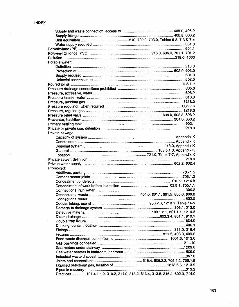
Supply and waste connection. access to ................................................. 405.0. 405.2 Supply tinings ........................................................................................... 408.8, 603.2 Unit equivalent .............................................. 610 . 702.0, 703.0, Tables 6.3, 7-3 & 7-4 Water supply required ........................................................................... ........... 601.0
Polyethylene (PE) ....................................................................................................... 604.1 Polyvinyl Chloride (PVC) ........................................................... 218.0, 604.0, 701.1. 701.2 Pollution ............................................................................................................. 216.0. 1003 Potable water:
Definition ............................................................................................................. 21 8.0 Protection of ............................................................................................. 602.0, 603.0 Supply required ................................................................................................... 601.0 Unlawful connection to ........................................................................................ 602.0
Poured joints ............................................................................................................ 705.1.2 Pressure drainage connections prohibited ................................................................ 805.0 Pressure, excessive. water ......................................................................................... 608.2 Pressure losses, water .............................................................................................. 610.0 Pressure, medium gas .............................................................................................. 121 6.0 Pressure regulator, when required .......................................................................... 608.2-6 Pressure, regular, gas .............................................................................................. 1218.0 Pressure relief valve ............................................................................. 608.0, 505.3, 506.2 Preventer, backflow ......................................................................................... 204.0, 603.2 Primary settling tank .............................. .......... ........................................................... 902.1 . . Private or private use. defin~t~on ................................................................................... 218.0 Private sewage:
Capacity of system ..................................................................................... Appendix K Construction ............................................................................................... Appendix K Disposal system .............................................................................. 218.0. Appendix K General ..................................................................................... 103.5.1.3, Appendix K Location ......................................................................... 721 .O. Table 7-7, Appendix K . . Private sewer. definition .............................................................................................. 218.0
Private water supply ....................................................................................... 602.2, 602.4 Prohibited:
Additives, packing ............................................................................................. 705.1.5 Cement mortar joints ......................................................................................... 705 . 1 . 2 Concealment of defects .......................................................................... 310.2, 1214.3 Concealment of work before inspection .............................................. 103.5.1, 705.1.1 Connections, rain water ........................................................................................ 306.2 Connections, waste ................................................. 404.0. 801 .l, 601.2, 805.0, 806.0 Connections, water .............................................................................................. 602.0 Copper tubing. use of ........................................................ 903.23 1210.1. Table 14-1 Damage to drainage system .................................................................... 306.1, 313.0 Defective material ........................................................... 103.1 2.1, 301.1 .l. 1214.3 Direct drainage ............................................................................ 603.3.4 801 .l, 810.1 Double trap fixture .............................................................................................. 1004.0 Drinking fountain location ..................................................................................... 406.1 Fittings ...................................................................................................... 31 1 .O. 316.4 Fixtures .......................................................................................... 31 1.5, 406.0, 409.2 Food waste disposal, connection to ..................................................... 1001.3, 1013.0 Gas bushings concealed .................................................................................. 121 1.10 Gas meters under stairway ................................................................................ 1209.6 Gas water heaters in bathroom, bedroom .......................................................... 509.0 Industrial waste disposal ...................................................................................... 307.0 Joints and connections .............................................. 316.4, 606.2.2, 705.1.2, 705.1.5 Liquified petroieum gas, location of .................................................... 1213.56. 1213.9 Pipes in masonry .................................................................................................. 313.2 Practices ............ 101.4.1.1.2.310.2,311.0, 313.2,313.4, 313.6.316.4, 602.0. 714.0

UNIFORM PLUMBING CODE
Receptors. location of ........................................................................................... 804.1 Trap joints ........................................................................................................... 1003.0
.................................................................................................................. Traps 1004.0 Trough type urinals ............................................................................................... 406.1
. Union couplings in gas piping ........................................................................... 1211 10 Urinals and water closets on combination waste and vent ................................... 910.7 Water jacketed grease interceptor ..................................................................... 1 0 1.7 Water piping in drainage or sewer trench ............................................................. 720.0 Zinc alloy die cast components ............................................................................ 403.1
Property line. termination of vent ................................................................................ 906.2 Protection from:
Corrosion ............................................. 313.1. 313.5. 609.3.1. 121 1.5. 121 1.7. 1218.8 Freezing ............................................................................................................... 313.6
Protection of: Flue or vent pipes ................................................................................................. 515.0 Piping materials and structures .................................... 313.0. 1211.3. 121 1.5. 121 1.7 Potable water supply ............................................................................................ 603.0 Trap seal ................................................................................. 1002.1. 1005.0. 1007.0 Water heaters ................................................................................ 505.3. 506.2. 510.0
Public. or public use, definition .................................................................................... 218.0 Public sewer. definition ................................................................................................ 218.0 Public shower floors .................................................................................................... 412.1 Public toilet rwm. definition ........................................................................................ 218.0
-Q - Quality and weight of materials. general regulations ........................................... Chapter 3
. Quality of fixtures ......................................................................................................... 401 0 Quick-disconnect device ........................................... 1208.8. 1207.3. 121 2.0(8). Table 14-1
-R- Rain and surface water drains .......................................................................... 306.2. 714.2 Rainwater systems ........................................................................ Chapter 11. Appendix D Rate of flow. fixture unit ................................................. 702.0. Table 7.3. 610.0. Table 6-3 Reamingpipes ......................................................... 310.3. 609.1. 701.2.1. 903.4. 1210.2 Receiving tankor sump ............................................................... 710.2.3. 710.7-10. 710.12 Receptors:
Accessible ................................................................................................ 804.1. 81 1.4 Approval required ..................................................................................... 802.0. 804.1 Connected indirectly to sewer .......................................................................... 801 . 1.2 Definition .............................................................................................................. 202.0 Inpirect waste ........................................................................................................ 804.0 Maximum distance from fixture ....................................................... , ................. 804.1 Required ................................................................................................ 801 .l- 2. 81 1.1 Shower. shower stalls ......................................................................................... 410.0 Size of trap. vent. waste ...................................................................................... 803.0 Type and size ...................................................................................................... 804.1
Recessed or Durham fittings ...................................................................... 206.0. 701.2.1 .................................................................................................. Reclaimgd water Appendix J
Recommended loadings. sewage disposal ....................................... Table 7-5. Appendix K Reducer. where required ............................................................................................ 317.0 Refrigerators .............................................................................................. Table 7.3. 801.2 Regulators. gas supply .......................................................................................... 1218.4-7 Regulators. relief valves on water supply ............................................................ 608.2.6 Relief vent: ....................................................................................................... 220.0. 907.0
Connections ; ....................................................................................................... 805.0 For closed mndensers. sumps. interceptors ...................................... 810.1.2. 1009.0

INDEX
Repairing: Defective gas pipe. prohibited ........................................................................ 1214.2.3 Defective pipe and fittings ................................................................................ 101.5.2
Repairs and alterations to plumbing and drainage system ................................... 101.4.1.1 Required:
Plans ................................................................................................................... 101.3 Plumbing fixtures ................................................................................................. 412.1 Sewer connections ................................................................................... 304.0, 305.0 Vents ................................................................................................................... 901.0
Responsible for testing ......................................................................................... 103.5.4.2 Restaurant, grease trap ........................................................................................... 101 1.0 Retesting .............................................................................................................. 103.5.6.2 Rim:
Definition ............................................................................................................. 220.0 Flood level .................. 208.0. 603.3.4, 603.4.2, 603.4.5. 603.4.9,701.1, 905.3, 909.0
Rise: Horizontal vent ................................................................................................... 905.3 Vents above fixture .............................................................................................. 905.3
Riser ................................................................................................... 220.0, 610.1, 121 1.5 Roof drains ................................................................................... 220.0, 306.2, Table 14-1 Roof, termination of vents above ................................. 517.1. 517.3.4, 906.1, 906.3. 906.7 Roof supply tanks .................................................................................... 607.0, Table 14-1 . . Roughing-in , definit~on ................................................................................................ 220.0 Running water, required ............................................................................................. 601.1
- S - Saddle, sleeve. band outlets. prohibited ................................................................... 31 1.1 Safety and health ..................................................................................................... 101.5.2 Safety devices ...................................... 505.3. 506.2, 603.3.15, 608.0, 1007.0, Table 14-1 Sand interceptor:
Cleanout for ...................................................................................... 707.8. Table 14-1 Definition; see "Interceptof Design .................................................................... 1009.1 , 1009.3, Tables 7-3 & 14-1 Required ................................................................................. 1008.1, 1009.0, 1010.0 Required for steam exhaust or blow-off ........................................... 810.0. Table 8-1 Secondary ........................................................................................................... 902.1 Type of trap ....................................................................................................... 1009.2 Vent required and not required ................................... 901.0. 902.0, 1002.1-2, 1002.4 Water seals ....................................................................................................... 1007.0'
Sanitary plumbing test ....................................................................... 103.5.5.1, Table 14-1 Sanitary tees. permissible use .................................................................................. 706.2 Screw pipe, supporting of ........................................................................................... 314.0 Screw pipe to cast iron ............................................................................................ 705.3.3 Screw pipe to copper tubing .................................................................................... 316.2.1 SDR, definition ............................................................................................................ 221.0 Seal, trap; see "Trap Seal" .......................................................................... 1005.0, 1007.0 Sealed combustion-type water heater ......................................................... 509.0, 510.2 Screw joints ............................................................. 316.2.1, 705.3.3. 121 1 .l, Table 14-1 Secondary energy protection ........................................................................... 505.3, 506.2 Secondary sand interceptors ...................................................................................... 902.0 Secondary temperature limiting device .......................................................... 505.3, 506.2 Seepage lines .................................................................................................. Appendix K Seepage pit: ...................................................................................................... Appendix K
Abandoned ................................................................................................ Appendix K Construction .............................................................................................. Appendix K Location .............................................................................................. 721 .O. Table 7-7

UNIFORM PLUMBING CODE
Size ........................................................................................................... Appendix K Soil absorption ........................................................................................... Appendix K
Self-cleaning traps .................................................................................... Table 7.3. 1003.1 Separate plumbing and drainage systems ................................................................. 312.0 Separate venting .......................................................................... 522.1.4. 81 1.6. 906.3 Separator .................................................................................................................. 1009.0 Septic tanks: ............................................................................. 221 .O. 301.1.1. Appendix K
Abandoned ............................................................................. 722.2.5. Appendix K Connections to sewer prohibited ......................................................................... 714.3 Location of .......................................................................................... 721.0. Table 7-7 Wastes. connection to ......................................................................................... 714.3
Service. authority to render gas ............................................................................... 1206.0 . . Service piping. gas. defin~tion .............................................................................. 1202.9 Setting fixtures .............................................................................................. 316.3.1. 408.5 Settling tank ................................................................................................................. 902.1 Sewage:
Definition ......................................................................................................... 221 . 0 Disposal of .................................... 303.0. 305.0, 709.0. 713.0. 714.0. 1010.0. 1014.0
Sewage disposal system. prhrate: ..................................................................... Appendix K Construction ........................................................................................................ 713.3 Holding tank ........................................................................................................ 714.6 Location ............................................................................................... 721 .O. Table 7-7
Sewage ejector. definition .................................................................................... 221.0 Sewage pump. definition ......................................................................................... 221.0 Sewers: ................................................................................................................. C h a r 7
Abandoned .......................................................................................................... 722.0 Adjacent to walls ..................................................................... 715.1, 718.3. Table 7-7 Available ................................................................................... 305.2. 713.2. 713.4 Building. material of ............................................................................ 701 .O. 715.1 Building sewer ................................................................................... 204.0. Chapter 7 Cleanouts ............................................................................................................ 719.0 Connection to. required ................................................................. 304.0. 305.0. 713.0 Construotion of ....................................................................... 715.0.719.0. Table 7-7 Damage to ..................................................................................... 306.1. 714.1. 81 1.1 Depth of .................................................................................................... 708.0. 718.3 Easements for ..................................................................................................... 721.2 Ejectors ............................................................................................................... 71 0.2 Existing ................................................................ 101.4.1.1.1.2. 312.0. 705.1.2. 713.6 Grade and support of .................................................................... 706.0. 713.6, 718.0 Independent system required ....................................................................... 312.0 Inspection, order of ........................................................................................... 103.5.1 Installed on made or filled in ground .................................................. 103.5.1.4. 718.2 Location ................................................. 308.0. 313.0. 718.0, 720.0, 721.0, Table 7-7 Materials .................................................................... 101.4.1.1.2. 715.1, 718.3, 720.0 Mobile home ............................................................................. 215.0, Appendix E Must be on same lot as building .................................................... 308.1. 312.0, 721.1 Pipe joints ...................................................................... 705.1. 705.3.1. Table 14-1 Private sewage disposal system ................................... 218.0. 305.1-2, 713.1-2, 713.6 Public. definition .................................................................................................. 218.0 Public. damage to ..................................................................................... 306.1. 714.1 Required .................................................................................. 305.1 2 71 3.1-2, 713.6 Size of building ........................................................................ 710.5. 717.0. Table 7-8 Testing of .................................................................................................... 101.4.1.1.2 Water pipe in trench ........................................................................................ 1108
Shall, definition ............................................................................................................ 221.0 Sheet lead .................................................................................... 701.3. 412.8. Table 14-1

INDEX
Shieided couplings ......................................................................................... 221 .O. 705.1.8 . . Shock assestor. definition ........................................................................................... 221.0 Short turn 114 bend. prohibited ........................................................................ 31 1.5. 706.1 Should. definition ........................................................................................................ 221.0 Shower stall or comparlment ...................................................................................... 412.7 Showers. gang. drainage ........................................................................ 412.10. Table 7-3 Shower pans ............................................................................................................... 412.8 Shower receptors ....................................................................................................... 412.8 Shutoffvalves ........................................................... 605.3. 710.4. 1209.3. 1211.9. 1213.3 . . Single family dwelling. definition ................................................................................. 221 . 0 Sinks:
Chemical. special use ......................................................................................... 403.0 Island ................................................................................................................... 909.0 Prohibited ........................................................................................................... 406.3 Restaurant ........................................................................................................... 403.0
Sinks and laundry tubs .......................................................................................... 1001.2-3 . . Types prohibited ................................................................................................. 406.3
Size of: Building sewer ......................................... 703.0. 705.0. 717.0. Tables 7-3. 7-8 & 14-1 Cesspool .................................................................................................... Appendix K Combination waste and vent piping ..................................... 805.0. 910.0. Appendix B Combustion air vents ................................................................................ 506.1. 507.1 Disposal field .............................................................................................. Appendix K Drainage piping. minimum ......................................... 703.0. 707.3. 707.10. Table 7-3 Gas piping system .............................. 1216.1. 1217.0. 1218.6.7. Tables 12-5 to 12-8 indirect waste pipes ............................................................................................. 803.0 Pipe cleanout ................................................................................... 707.1 1. Table 7-6 Seepage pit ................................................................................................ Appendix K Septic tank .............................................................................. Table 7-3. Appendix K Trap .................................................... 702.0. Table 7-3. 910.4. 910.6. 1003.3. 1006.0 Vent pipes ........... 710.10.810.1. 904.0.905.4. 908.3. 908.2.908.3. 910.3. Table 7-5 Vent pipes. water heater .......................................... 506.1. 512.3. 518.0. 519.3. 520.2 Vent stack ............................................................................... 904.0. 907.1. Table 7-5 Water piping ........................................................................................................ 610.0
Slaughter houses ...................................................................................................... 1010.0 Slip joints ...................................................... 316.1.4. 705.1.6. 705.1.8-9. 705.4.1. 705.4.3 Slip joints . traps .......................................................................................... 705.4.1. 1003.2 Slope; see "Grade" Smoke pipe or flue ..................................................................... 502.1. 506.1. 51 9.0. 522.0 Softener ................................................................................................... 610.2. Table 14-1 Soil pipe ...... 221.0.311.2.311.4.311.6.704.3.1. 704.3.3. 705.1.9.722.2.801.1-2. 1002.4 Soil porosity ...................................................................................................... Appendix K Soil stack . minimum size ........................................................................................... 703.0 Solder. bushings and ferrules ...................................... 316.1.2. 701.4.2. Tables 7-1 & 7-2 Solder fluxes ............................................................................................................ 316.1.3 Solder joints .................. 221 .O. 316.1.2.3.316.2.1. 316.3.1.410.5 (note). 608.2.1. 705.3.4 Spacing:
Gas risers or meters ............................................................................. 1209.2. 121 1.5 Pipe supports .......................................................................... 314.1. 314.7. Table 3-1
Special fixtures ............................................................................. 403.0. 407.0. Table 14-1 . . Special jolnts ..................................................................................... 316.2.1. Table 14-1 Special waste pipe: see "Industrial Waste Pipe" Special wastes:
Acid and chemical .................................................................................. 81 1 .O. 1008.1 Definition ............................................................................................................. 202.0 High temperatures .............................................................................. 810.1. Table 8-1

UNIFORM PLUMBING CODE
Laundries. bottling works. wash racks ............................ 702.0. 71 1 .O. 1008.1. 1010.0 Specific gravity. natural gas ..................................................... 1216.1. Tables 12-4 & 12-6 Specifications for materials ............................................................... Chapter 3. Table 14-1 Stack ...................................................... 221 .O. 31 1.4. 705.4.2. 71 1 .O. 904.0. 906.1. 907.0 Standards for materials .................................................................... Chapter 3. Table 14-1 Standpipe. clotheswasher .......................................................................................... 604.1 Steam boiler. water connection to ......................................................................... 603.3.10 Steam exhaust condenser or blow-off ....................................................... 810.0. Table 8-1 Sterile equipment ........................................................................................................ 806.0 Storage tanks:
Gravity .............................................................................................. 607.0. Table 14-1 Hot water ............................................................................... 505.3. 508.2. Table 14-1 . .
Storm drain. defin~t~on ................................................................................................. 221.0 Storm sewer. definition ............................................................................................... 221.0 Strainers ........................................................................................................... 405.1. 410.1 S-trap prohibited ....................................................................................................... 1004.0 Street main; see "Water main" ....................................................... 225.0. 610.7. Table 6-4 Structural condition safety .......................................................................................... 313.0 Studding and joists. cutting of ..................................................................................... 313.2 Sub-drain. shower stalls ............................................................................................. 410.5 Subsoil drain. definition .............................................................................................. 221.0 Submittal of plans ....................................................... 101.3. 103.2.1.4. 103.3.1. 103.4.2-3 Subsoil drainage ....................................................................................................... 710.1 2 Substitute materials .................................................................................................... 301.0 Subsurface disposal field .................................................................................. Appendix K Suds relief .................................................................................................................. 711 . 0 Sump:
Boiler room. installation ............................................................................ 810.1. 810.3 Building. backwater devices ................................................................................ 710.2
..................................................... Building drainage systems below sewer level 710.2 Condensers ........................................................................................ 810.0. Table 8-1 Construction ........................................................................................................ 610.2 Definition ............................................................................................................. 221.0 Pump connection permitted ...................................... 710.2-3. 710.9. 805.0. Table 7-4
..................................... Pump discharges, conversion to fixture units 710.4. Table 7-4 Sewage ............................................................................................................... 710.0 Vent ............................................................................. 710.7. 710.10. 810.1, Table 6-1
Supply: Control valves. water ................................................................................ 605.5. 605.7 Fifflngs. fixtures ................................................................................................... 408.6 Fixture. definition ................................................................................................. 206.0 Hot water .................................................... 103.5.3.3. 601.2. 602.1. 604.1, 610.12-13 Non-potable water ......................................................................... 603.3.1 1, 610.14(6) Pipe. size of ............................................................................. 608.2. 610.0. Table 6-5 Potable water. protection ...................................... 603.0. 603.2.4. 603.3.10. 603.3.12 Tank. water ......................................................................... 605.3. 607.0. 608.1. 606.3 Trap . seal ................................................................................ 1004.0. 1005.0. 1007.0 Water, quality of. source of .................................................................................. 601.1
Supports and Hangers .... 221.0.314.0.515.0.609.1.906.4.1211.8. Tables 3.1.1 2-2 & 14-1 Surface water. discharge ......................................................... 307.2. 714.2. 61'1 .l, 1010.0 Surrounding material. urinals .................................................................................. 408.4-5 Sweat joints .............................................................................................. 316.3. 316.2.1 System:
Combination waste and vent .................................................................... 205.0. 910.0 Defective, testing of ....................................................................................... 103.5.5.1 Drainage ................................................................................................... 205.0. 712.0

. . Durham. defin~t~on .............................................................................................. 202.0 Gas piping. size of .................................................................... 1210.1. 1216.0.1218.0 Independent ........................................................................................................ 312:O Interconnection of gas piping ............................................................................ 1215.0 . . Plumbing. definit~on ............................................................................................. 202.0 Vent ........................................................................................................... 224.0. 712.0 Water supply ................................................................................. 225.0. 609.0. 712.0
-T - Tailpiece:
Connection ........................................................................................... 807.2. 910.5.6 Maximum length of .............................................................................................. 910.5
Tanks: Automatic flushing, urinals .................................................................................. 409.1 Boiler blow-off: see "Condensers" .................................................... 610.1, Table 8-1 Flush ........................................ 208.0. 404.0, 408.4, 41 1.2, 601 .l, 603.3.2. Table 7-3 Gravity supply ...................................................................................................... 607.0 Hot water storage ............................................................... 505.3, 506.2, 608.3, 608.6 Inlet to ........................................................................... 603.4.2, 603.4.5. 710.9. 810.1 Liquified petroleum ................................................................ : ....... 1213.0, 1217.4 Material' .................................................................................. 710.8, 810.2, Table 14-1 Primary settling .................................................................................................... 902.1 3eptic;see "septic Tank Water closet ................................................................. 404.0. 406.1. 601 .I. 603.4.2.3 Water supply ...................................................................... 602.1. 607.0. 608.1. 608.3 Water supply. overflow .............................................................. 603.4.2. 607.0. 805.0
Temperature limiting devices .......................................................................... 505.3. 506.2 Temperature relief valves ........................................................................ 608.0. Table 14-1 Temporary use of gas ............................................................................................... 1208.0 Termination of vents ...................................................................................... 51 7.0. 906.1 Tests:
Advance notice for ......................................................................................... 103.5.4.1 Air ................................................................................. 103.5.3.3. 103.5.3.5, 1204.3.2 Alternate materials, methods ....................................................................... 301.2.4.5 Building sewer ............................................................. 101.4.1.1.2, 103.5.1.3-4, 723.0
... Concealing of work prohibited before inspection 103.5.1 .l, 103.5.1.3.4, 1204.3.1 -2 Exceptions ...................................................................................... 103.5.3.5, 1204.4 Final .................................................................................. 103.563 712.1. 1204.3.2 Labor and material for ...................................................................... 103.5.4.2, 1204.2 Percolation ................................................................................................. Appendix K Required ............................................................................................... 03.5.3 603.3.2 Responsibility for ........................................................................................... 103.5.4.2 Sanitary plumbing ......................................................................................... 103.5.5.1 Testing agency ......................................... 301.2.4. 502.12(2). 505.1-2, 610.2, 1202.2 Waived .......................................................................................................... 103.5.3.4 Water supply system .................................................. 103.5.1.1. 103.5.3.3, 609.4
Threaded joints ........................................................................... 316.1.1. 316.2.1, 705.3.3 Threaded fittings ............................................................. 311.2. 316.1.1, 316.2.1, 705.3.3 Thread lubricants ........................................................... .......... 316.1 .l, 121 1 .l, 1213.7 Three compartment sinks ....................................................................................... 1001.2 Toilets:
Connections ........................................................................................................ 316.4 Prohibited type ................................... .... ............................................................ 406.1
Trap ............................................................................................................... 202.0. 1003.0 Arm ........................................................................ 222.0, 1002.2-3, Tables 7-3 & 10-1 Drum .................................................................................................................. 1004.0

UNIFORM PLUMBING CODE
Exceptions for ................................................................................... 1001.2.3. 1002.3 Floor drain ............................................................................... 1003.1. 1006.0. 1007.0 For sumps. condensers ....................................................................................... 810.1 For three compartment sinks or three lavatories ............................................... 1001.2 From fixture. distance of .................................................................................... 1001.4 From vent. distance of ..................................................... 704.2. 1002.2. Table 10-1 Grease ................................................... 209.0. 1014.0. 103.0. Tables 1.1. 7-3 & 10-2 Ground metal joints .......................................................................................... 705.4.4 Horizontal distance from vent ............................................. 704.2. 1002.2. Table 10-1 Indirect connection required ........................................................................... 801.0 Industrial interceptors and separators ............................................................... 1009.0 Integral .............................................................................................................. 1001.0 Material of .............................. 103.1.2. 301.1 .l-2. 705.4.1. 807.3. 1003.1. Table 14-1 Minimum size .............................................................. 702.0. 1003.3. Tables 7-3 & 7-5 Prohibited types ................................................................................................. 1004.0 Protection ......................................................................................... 603.3.4. 1002.1 -2 Required ............................................................................................................. 100 . 0 Seal ........................................................................................... 222.0. 1005.0. 1007.0 Separate for each fixture ................................................................................. 1001 . 1 Size ................................................................................................. 1003.3 Table 10-1 Slip joints in ......................................................................................... 705.4.1. 1003.2 Supplies for ................................................................................................. 1007.0 Union joint in water seal ................................................................... 316.2.2. 1003.2 Unit loading .................................................................................. 702.0. Table 7-5 Vents for ........................................ 103.1.2..810.1. 901.0. 905.2. 905.5. 908.1. 909.0.
9\(0.6,1002.0,1001.5, Tables 7-5 & 10-1 Vent not required for ....................................................................................... 902.0 Water seal .......................................................................................................... 1005.0 Weir ............................................................. 415.0. 905.5. 1001.4. 1002.2. 1002.4 Where required .................................................................................................. 1001.0
Trenching. excavation and backfilling .................................................. 315.0. 718.0. 720.0 Trough urinals. prohibited .................................................................................... 406.1 Tubing. copper ............................................. 316.1.3. 316.2.1. 604.1-2. 606.1 . 1. 606.2.1.
609.3.2,701.1.4-5,705.4.3, Table 14-1 Tubing. gas connectors ............................................................................................ 1212.0 Tunneling .................................................................................................................... 31 5.2
-U- Unconfined space. definition ........................................................................................ 223.0 Underground:
Copper tubing ........................................................................................ 604.2, 701.1.4 Dosing tanks ............................................................................................... A n d K Drainage material ............................................................................. 316.2.2. 701.0 Gas piping ................................................................................................... 121 1.0 Vent material ................................................................ 316.2.2, 701.1.4, 903.1.1, 903 Water pipes .............................................................................................. 609.0, 720.0
Unions: Couplings, in gas piping .................................................................................... 121 1.0 In vents ............................................................................................................. 316.2.2 Joint in seal of trap ............................................................................. 705.4.1, 1003.2 Where allowed ................................................................................... 316.2.2. 121 1.10
Unit, fixture ..................................................... 208.0. 610.0. 702.0, Tables 6-3 to 6-6 & 7-3 Unit loading of traps .................................................................................................... 702.0 Unlawful connections .................................................................................................. 602.0 Unsanitary, definition .................................................................................................. 223.0 Unusually tight construction ................................................... ......... 502.7. 507.2. Table 5-1

INDEX
Urinals ................................................ 316.3.1. 402.2. 404.0. 406.1. 408.6. 410.0. 601.1. 707.4(1), 1003.1, Tables 7-3 & 7-5
Use of alternate material ............................................................................................ 301.2 Use. private. definition ................................................................................................ 218.0
- v - Vacuum breaker ............................... 224.0. 409.0. 603.0.603.3.15. Tables 1.1. 6-1 7 14-1 Vacuum relief vent. definition ................................................................................ 224.0 Validity of code ............................................................................................. 103.7.1. 103.8 Valves ........................................................................................ 31 1.7. 605.0. Table 14-1
Backwater ............................................................................................................ 710.0 Check ........................................................................................... 603.1.3.5. Table 6-2 Spring loaded .................................................................................................. 121 1.11 . . Flush . defin~tcon ................................................................................................... 208.0 Flushometer ........................................... 41 1.2.3. 603.3.1. 603.3.3. 610.10. Table 6-6 For drainage ..................................................................................... 710.4. Table 14-1 For water ................................................................................................ 41 2.1 0. 605.0 Hose outlet protection ...................................................................................... 603.3.7 Required ........................................................................................... 605.0. 121 1.9.15 Temperature and pressure relief ...................................................... 608.2. Table 14-1 Water control ..................................................................................................... 41 0.10
Vaults. for gas meters ............................................................................................... 1209.5 Vent or vent pipe:
Below trap weir ....................................................................................... 905.5. 1002.4 Branch. definition ............................................................................................ 204.0 Changes in direction of ........................................................................................ 903.4 Chemical ............................................................................................... 81 1.2. 81 1.5.6 Combination waste system design ...................................... 205.0. 910.0. Appendix B Common vent .................................................................. 205.0. 519.0. 523.3.1. 908.3 Connections ................................................................. 31 1.2. 805.0. 905.1. Table 8-1 Connectors ........................................................... 513.2. 514.0. 515.0. 516.4.5, 524.3 . . Continuous. definlt~on .......................................................................................... 205.0 Distance of trap from ...................................................................... 1002.2. Table 10-1 Double fitting for ....................................................................................... 704.2. 905.0 Drain and waste .......................................................................... Table 7.3. Chapter 7 Fittings ........................................................................................................... Table 7-5 Fixtures. back to back ........................................................................ 704.2. 905.6 Flagpoling. prohibited .......................................................................................... 906.3 Flashing for ...................................................................... 313.8. 517.1. 906.1. 906.5 Grade of .................................................................................................. 905.1. 905.3 Height above fixture ................................................................................. 905.3. 909.0 Height above ground ................................................................................ 517.5. 906.4 Horizontal .......................................................... 516.1. 516.3. Table 7.5. 904.2. 905.3 Indirect waste ....................................................... 801 .1.2. 803.0. 805.0. 810.1. 902.0 . . Individual. defintt~on ............................................................................................. 202.0 interceptors ............................................................................................ 902.1. 1008.4 Island sinks and fixtures ..................................................................................... 909.0 Length of ............................................................................................ Table 7.5. 904.0 Material for .................................................................................... 514.1. 811.2. 903.0 Methodof installation .................. 311.5.501.0.512.5.6.520.1. 523.3. 903.1.2.906.4 Minimum size in each building ............ I .............................................. Table 7.5. 904.0 Not required .............................................................................................. 803.0. 902.0 Not to be used as soil or waste pipe ..................................................... 31 1.4. 601.1 -2 Opening location ................................................................................. 905.5. 1002.4 Parallel. connection ............................................................................................. 907.1 Pipe. grade and connection ................................................................... 905.1. 905.3

UNIFORM PLUMBING CODE
Prohibited location of .......................................................................... 903.1 .l- 2. 903.3 Receptors ......................................................................................... 81 1.2, Table 14-1 Relief ................................................................................ 222.0. 805.0. 907.0, 1008.4 Required ........................................................................................ 710.0, 901.0, 904.1 Required separateiy on every trap ............ : ............................ 901 .O, 902.1, 1002.1-2 . . Slz~ng ..................................................... Table 7.3, 710.0, 904.0, 905.4, 908.0, 910.4 Special ............................................................................................... Chapter 8, 909.0 Stack .................................................................................. 224.0, 31 1.4. 906.1, 907.0 Steam, exhaust ................................................................................................... 810.0 Sump .......................................................................... 710.7. 710.10. 810.1. Table 8-1 System, definition ................................................................................................ 202.0 Ten stories or more ............................................................................................. 907.1 Termination .............................................................................................. 517.0, 906.0 Undiminished through roof ....................................................................... 905.4, 907.1 Unit loading ................................................................................................... Table 7-5 Vertical wet; see "Wet Vent" Wet; see "Wet Vent" Yoke ......................................................................................................... 227.0, 907.0
Vent connector ........................................................... 513.2. 514.0, 515.0, 516.4.5, 524.3 Vent manifold, gas ..................................................................... 519.4, 523.3.1, 1218.4(1) Vent or vent flue ......................................................................................................... 502.0 Ventilation for gas water heater enclosures .................................................... 506.1, 507.1 Vertical pipe: ........................................................ 224.0, 703.0, 704.2, 905.6, 908.2, 910.5
Unit loading length-drainage piping .............................................................. Table 7-5 Piping, support of ................................................................................................ 314.0
Vertical to horizontal drainage fittings ............................................... 706.4, 905.2-3, 909.0 Vertical wet venting; see Wet Venr Violation, notices of .............................................................................................. 103.5.6.1 Vitrified clay ................................................................. 701.1-2, 705.3.1. 811.2, Table 14-1
- W - Wall. extension through ................................................................................... 313.1. 514.3 Wall-hung fixtures. installation of .................................................. 316.3.3. 408.2. 408.4.6 Wall-hung water closets. definition ............................................................................. 225.0 Wall . recess or channel in ........................................................................... 313.2. 121 1.15 Wash racks. auto ........................................................................................... 805.0. 101 1.0 Waste ................................................................................................................ Chapter 7
...... Chemical laboratory. photographic ...................................................................... 81 1.0 Cooling water ........................................................................................... 801 .O. 808.0 Combination ......................................................................... 205.0. 901 .O. Appendix B Continuous ........................................................................... 205.0. 405.3.4. Table 7-3 Detrimental or harmful ................................................... 306.1. 307.0. 81 1.1. 1009.1 Fwd. disposal unit; see "Food waste disposal unit" Indirect ............................................................... 21 1 .O. Table 7.3. Chapter 8. 902.0 Industrial ...................... 211.0. 307.0. 811.1. 903.2.3. 1001.3. 1009.0. 1010.0. 1014.0 Liquid ....................... ., ................... 214.0. 303.0. 304.0. 710.2. 811.1. 1008.0. 1009.1 Pipe. definition ................................................................................................... 2018.0
Buildings over ten stories ............................................................................. 907.1 For refrigerators ........................................................................... Table 7.3. 801.2 Indirect .................................................................................... 21 1 .O. 801.0. 805.0
Accessibility .............................................................. ......................... 804.1 Airbreak ................................................................................................. 801 . 0 Airgap for ...................................................................... 603.3.4. 801 .O. 806.0 Installation of ....................................... 313.6. Table 4.1. 802.0. 803.0. 810.0
Material of. inside building ............................................................................ 701.0 Number of fixtures allowed on ........................................................... Table 7-5

......................................................................................... Size of Tables 7-3 & 7-5 Pretreatment required .................. : ...................................................... 81 1 .l. 101 1.1 Receptor. prohibited location ............................................................................... 804.1 Special. definition ................................................................................................. 202.0 . . Stack, defin~t~on ................................................................................................... 202.0
Water: Additions to existing work ............................................................. 101.5.1, 610.14(2) Building supply ..... ; ..................................................... 604.1. 609.5. 610.0. Table 6-5 Conditioning ....................................................................... 225.0. 603.0. 609.4. 610.2 . . Distributing plpe. definition ................................................................................ 202.0 Distribution system ....................................................................................... Chapter 6 Filter .................................................................................................................... 610.2 Hammer arrestor. definition .................................................................................. 225.0 Main. definition .................................................................................................... 225.0 Non-potable lines .......................................................................... 603.4.1 1. 610.14(6) Piping:
Grounding ..................................................................................................... 604.8 In sewer trench ....................................................................... 315.0. 609.2. 720.0 Installation of ....................................... 313.6. 603.3.4. 604.8. 609.0. 610.0. 720.0 Material ..................................................................................... 604.0. Table 14-1 Sizing ............................................................................... 610.0. Tables 6-4 & 6-5 Test ........................................................................................................... 103.5.3
Potable ...................................................... 218.0. 316.1.3. 501.0. 602.0-603.0. 604.5, 604.7, 604.10,607.0,608.2.610.1-2,610.14(7)
Pressure: Excessive ................................................................................................. 608.2-6 Inadequate ................................................................................................... 608.1 Loss ............................................................................................................... 610.0 Regulators and relief valves ...................................................................... 608.2-6
Private supply ..................................................................................... 602.4. Table 6-4 Prohibited materials ......................................... ................................................. 604.10 Protection of potable ........................................................................................... 603.0 Required .................................................................................................. 601.1. 610.3 Service. size ...................................................................................... 61 0.0, Table 6-5 Softener ............................................................................................ 610.2. Table 14-1 Supply:
............................................................... . Cross-connectors 601.1 602.3. 603.4.1 1 Flushometer valves; see "Flushometer valves" To fixtures ........................................................................ 610.0. Tables 6-4 & 6-5 . . System. definlt~on ........................................................................................ 221.0
Supply tank ............... : ........................................................ 603.4.2. 607.0. Table 14-1 Temperature limiting device ..................................... 502.13. 505.3. 506.2. Table 14-1 Test ......................................................................................................... 103.5. 610.2 Unlawful:
Connections ................................................................................................. 602.0 Devices ..................................................................................................... 602.3
Valves. control ........................................................................................ 412.10. 605.0 Water closets ................................... 316.3.1. 401.1. 404.0. 406.1. 408.0. 601.1. 603.3.1-3.
610.3,910.7, Tables 6-4 & 7-3 Water heaters:
Access ............................................................................................ 510.2, 51 1.0 Approved type required .............................................................. 501.0. 505.1.2. 506.1 Clearances .................................................................................................... 506.0 . . Combustton alr for ........................................................ 506.1. 507.0. 510.2. Table 5-1 Definition ........................................................................................................... 502.0 Enclosures ....................................................................... 507.2. 510.2. 511.0. 523.3.5

UNIFORM PLUMBING CODE
Gas ................................................................................... 505.0. 514.1. 524.4. 1213.6 Oil-burning and other ......................................................... 501 .O. 506.0. Table 14-1 Pressure relief valve ......................................................................................... 608.3-6 Prohibited location .................................................................... 508.0. 509.0. 1213.5-6 Protection ............................................................................... 505.3. 510.3. 501.5 Sealed combustion type .............................................................. 502.6. 509.0. 510.2 Venting of .................................. 501.0. 502.5.6. 502.8.12. 504.1. 506.1. 512.0.525.0
Waterproofing: Fixture setting ................................................................................. 316.3.1. 408.0 Flashings ....................................................................................... 313.8. 517.1. 906.5 Openings .................................................................................................. 313.8. 906.5
Water sealed traps; see "Traps" Water softener ......................................................................................... 610.2. Table 14-1 Water test:
Building sewers ............................................................................................. 103.5 Plumbing. drainage and vent system ....................................................... 103.5. 712.0
Water treatment device; see Water Conditioning" Weep holes. sub-drain of shower stalls ...................................................................... 412.8 Weight of flashing. lead .............................................................................................. 701.3 Weights and quality of materials .................... Chapter 3. 604.0. 906.6. 1210.5. Table 14-1 Welded lead joints ...................................................................................... 705.1.3. 121 1.2 . . Welder. pipe. definttcon ............................................................................................... 225.0 Welding or brazing joints ........................................... 316.1.6. 705.1.3. 121 1.2. Table 14-1 Well. distance from sewage disposal ...................................................... 721 .l. Table 7-7 Wet vent ................................................................................. 5 . 0 . 316.2.2. 908.0. 910.6 Whirlpool bathtub. definition ....................................................................................... 225.0 Window. termination of vents from .................................................................. 517.5.906.2 Wiped joints ................ : ........................................................................ 316.12 705.3.4 Wooden sinks and laundry trays ................................................................................ 406.2 Work. concealed .......................... 103.1.2. 103.5.1.2. 504.2. 1204.3.1-2. 1211.3. 1211.10 Work . existing .......................................................................................... 101.4.5. 207.0 Work. exposed. where required ... 103.1.2.103.5.1.2.504.2.1204.3.1-2. 121 1.3.'1211.10 Working space ............................................................................................................ 51 1.0 Workmanship ...................................................................................... 310.0. 609.1. 1203.0 Wrapping of pipe ................................................... 313.0. 609.3.1. 121 1.5. 121 1.7. 1218.8 Wrought iron (galvanized) ..................................................... 316.1.2. 604.1. 605.2. 701.1.
705.3.3-4,707.1.903.1, 1210.1, Table 14-1 Wye connections ................................... 405.4. 706.0. 707.6-7, 710.4..719.4. 907.2. 909.0
- X - X-ray darkrooms ......................................................................................................... 81 1.8
- Y - Yard piping. gas ........................................................................ 1202.0. 1211.0. 1217.0
-2 - Zinc alloy die cast components ............................................................................ 403.1


