upcycle the gyres navigation system · upcycle the gyres navigation system ... sub questions ......
TRANSCRIPT

Upcycle the Gyres Navigation System Project 2, Project group 6 – Rotterdam Mainport University
Project members: Jeroen Knoester [email protected] Jordano Hoevertsz [email protected] Kevin Jackson Verschuur [email protected]
Principal: Mr. G. Blankenstein
Group managers: Mr. P.C. van Kluiven [email protected] Mrs. M. van der Drift [email protected]
Final Version, March 27th Rotterdam

Upcycle the Gyres Navigation System
1
Table of Content Preface ........................................................................................................................................ 4
1. Introduction ......................................................................................................................... 5
Background ......................................................................................................................................... 5
Upcycle the gyres ............................................................................................................................ 5
The problem .................................................................................................................................... 5
The solution .................................................................................................................................... 5
The purposes of the vessel/ drone ................................................................................................. 5
Project Title ..................................................................................................................................... 6
Project managers ............................................................................................................................ 6
Project principal .............................................................................................................................. 6
Stakeholders ................................................................................................................................... 6
Aim (objective) and problem definition .............................................................................................. 7
Problem description ........................................................................................................................ 7
The aim ............................................................................................................................................ 7
Project assignment.............................................................................................................................. 8
Main question ................................................................................................................................. 8
Sub questions .................................................................................................................................. 8
Research Methods .............................................................................................................................. 9
Project borders ................................................................................................................................. 11
2. Onboard Control Station Communication ............................................................................ 12
Communication systems by satellite ................................................................................................ 12
Integrated Data Link System ......................................................................................................... 12
Navigation via Signals of Opportunity........................................................................................... 13
ORBIT Maritime VSAT AL-7109 ..................................................................................................... 13
Communication systems for ship-to-ship ......................................................................................... 14
The MORSE system ....................................................................................................................... 14
Conclusion ......................................................................................................................................... 15
3. External users control ......................................................................................................... 17
Main Communication system ........................................................................................................... 18
Internal Communication ................................................................................................................... 18
Additional Communication system ................................................................................................... 18
Reality to gaming .............................................................................................................................. 19
Conclusion ......................................................................................................................................... 19

Upcycle the Gyres Navigation System
2
4. Drone navigation (trough water and waste) ......................................................................... 20
The definition of a gyre ..................................................................................................................... 20
The North Atlantic Gyre .................................................................................................................... 21
The North Atlantic Garbage Patch ................................................................................................ 21
The South Atlantic Gyre .................................................................................................................... 22
The North Pacific Gyre ...................................................................................................................... 22
Eastern Pacific Garbage Patch ...................................................................................................... 22
Western Pacific Garbage Patch ..................................................................................................... 23
The South Pacific Gyre ...................................................................................................................... 23
The Indian Ocean Gyre ...................................................................................................................... 23
Gathering information about the garbage patch ............................................................................. 24
The working of the Wave Glider ................................................................................................... 24
Movement of the drone ................................................................................................................... 25
Conclusion ......................................................................................................................................... 25
5. Identification of recovered wastes....................................................................................... 27
Conclusion ......................................................................................................................................... 28
6. Keep up with the Regulations for Preventing Collisions at Sea .............................................. 29
Conclusion ......................................................................................................................................... 30
7. Berthing of the drone .......................................................................................................... 31
Laser guided berthing ....................................................................................................................... 31
Vacuum Mooring .............................................................................................................................. 31
Conclusion ......................................................................................................................................... 32
8. Emergency backup in case of blackout ................................................................................. 33
Why cooling, ventilation and air conditioning (HVAC)? .................................................................... 34
Conclusion ......................................................................................................................................... 35
9. Calamity plans .................................................................................................................... 36
In case of fire ..................................................................................................................................... 36
In case of Grounding ......................................................................................................................... 36
Conclusion ......................................................................................................................................... 37
Project Conclusion ..................................................................................................................... 38
Recommendations ..................................................................................................................... 40
References ................................................................................................................................. 41
APPENDIX I: ............................................................................................................................... 43
How is the regular trash sorted? .................................................................................................. 43

Upcycle the Gyres Navigation System
3
How does the REKAS-system works? ............................................................................................ 44
Appendix II: ............................................................................................................................... 45
Visit at Imtech: .................................................................................................................................. 45
Appendix III: .............................................................................................................................. 46
Interview with VSTEP ........................................................................................................................ 46
Nautis ................................................................................................................................................ 46
Appendix IV: ................................................................................................................................ 0
Appendix V .................................................................................................................................. 1

Upcycle the Gyres Navigation System
4
Preface All students at the Maritime University of Applied Sciences have to do research for a project called
'Project 2'. Every year a theme will be chosen by the principals. All second year students are divided
into different project groups, and all these project groups are going to do research to a topic that fits
with the main theme.
Our project group consists of the following group members:
Jeroen Knoester
Jordano Hoevertsz
Kevin Jackson Verschuur
We also like to thank Mr. A van den Dool for his support and help with making contact to the
companies.
In this report you can read everything about our research during this project, including problem
definition, (main) questions, and answers to those questions.

Upcycle the Gyres Navigation System
5
1. Introduction
Background
Upcycle the gyres
The “Upcycle the Gyres” initiative is based around the globe. It consists of a multinational group of
business and sustainability leaders, environmentalists, and innovators committed to pioneering the
new industry of Marine Plastic Eco-Recovery, and Upcycling. Upcycle the Gyres, an environmental
not-for-profit Society, will eventually transform into a for-profit corporation. This decision is based
on the need for physical remediation of plastic pollution from the marine ecosystem and the global
demand for fuel. Upcycle the Gyres Society is a diverse community of people working together to
accelerate existing eco-tourism, upcycling, and marine mining resources and practices into clean-up
action of the ocean currents
The problem
Plastic garbage floating in the world’s oceans is one of the most present environmental challenges
today. Right now there are five oceanic currents known as gyres, they are: North Pacific, North
Atlantic, South Pacific, South Atlantic and Indian Ocean. Approximately 142 billion kilos (142 million
metric Tons) of plastic waste floating on the oceans currents are polluting our marine environment.
Environmental concerns today, and in the future, will inevitably require the physical clean-up of
marine plastic deposits and its resulting ramifications. Marine plastic garbage degrades differently; it
breaks into chunks, disintegrates into micro fragments and or turns into glue that looks like jellyfish.
These plastics can sink and resurface elsewhere, swirl at different depths and others sink to remain
on the ocean floor.
The solution
Combining the processes of Marine Plastic Recovery and Upcycling to clean our oceans while re-
converting the waste materials into re-useable energy and resources. Marine Plastic Upcycling is the
process of recovering plastic wastes, from deposits on surface and on the seabed, and transforming
it into fuel. The very nature of upcycling is to transform waste into useful products.
Providing a multitasking drone that in co-operation with a mother ship can combine the process of
Marine Plastic Recovery and Upcycling to clean our oceans, and that operates at zero waste, low to
zero emissions, and at the lowest cost to organizations conducting research-work on the marine
plastic wastes in the oceans.
The purposes of the vessel/ drone
• To assist Marine Research Institutes and other organizations, foundations and coalitions in
their efforts to clean up the floating plastic wastes from the world’s oceans
• To develop the new industry of marine plastic mining for upcycling plastic deposits into fuel
• To provide a vessel for marine cleanup
• To increase the awareness of the plastic trash fields located in giant vortexes (Gyres) in every Ocean on Earth • To return trash that is not recyclable on board, to shore recycling facilities

Upcycle the Gyres Navigation System
6
Project Title
Upcycle the Gyres Navigation systems
Project managers
Mr. P.C. van Kluyven Mrs. M. van der Drift
Project principal
Mr. G. Blankenstein
Stakeholders
Upcycle the Gyres Represented by: Aart van den Dool Co-Founder and Conceptual Director

Upcycle the Gyres Navigation System
7
Aim (objective) and problem definition
Problem description
To develop a usable navigation system for the multitasking drone for the recovery of marine plastics
on our oceans. The main task of the vessel is to recover all the waste floating on the ocean in the
areas where giant patches of marine garbage are floating. The vessel and all its processes must be
automated to achieve a greener marine future with the most advanced technologies. The vessels
main source of energy must be sustainable energy, whether it’s by solar, wind, hybrid or a
combination of these resources.
Since the drone is unmanned, a few researches must be performed on how it’s going to be able to
recover the wastes and bring those wastes to the mother ship.
The upcycling process to convert plastic into fuel is going to take place on a floating eco-research-
upcycling facility (i.e. a ship, platform), which is equipped with the plastic-to-fuel conversion
machines. This facility will act as mother ship for the drone(s). The reason for choosing a floating
eco-research-upcycling facility is to assist Marine Research Institutes and other organizations,
foundations and coalitions in their efforts to clean up the floating plastic wastes from the world’s
oceans and to conduct research on the effect of marine plastic wastes in the oceans.
The aim
The aim is to develop a navigation system that will allow the drone(s) to safely navigate through a
giant patch of plastic wastes for the recovery of the wastes and afterwards to deliver these wastes to
the floating upcycling facility.

Upcycle the Gyres Navigation System
8
Project assignment
Main question
How to develop a navigation system for the fully automated drones, with the purpose of navigating
safely through the islands of marine plastic for the recovery of these wastes?
Sub questions
1. How can the onboard control station communicate with the drone, so that the drone could
be operated manually if required?
2. Is this control station the only one that can navigate the drone? Or could we make a system
at which external users (internet users) can navigate the drone while it's being monitored by
the onboard control station? In this case the onboard control station can overwrite external
users at any time.
3. How must the drone navigate through a giant patch of floating waste? By an in advance
planned route to navigate between the coordinates of the waste patch, for example a in a
spline movement or it navigates from one coordinates to another?
Image 1: Drone movement
4. How is the drone going to identify whether it is recovering waste or it’s navigating through
clean water?
5. How is the vessel going to keep up with the Regulations for Preventing Collisions at Sea?
Such as avoiding other vessels?
6. How is the drone(s) going to be guided through berthing near the facility?
7. In case of a blackout, what would happen with the vessel?
8. What would the plan in case of calamity? Such as fire, grounding, etc.

Upcycle the Gyres Navigation System
9
Research Methods The answer to the sub questions on how to develop a navigation system for the fully automated
drones lies in the methods of research. Every question needs its own method to be solved. The
research must be related to the researcher’s own experiments, observations and experience. For
that reason an empirical research must be carried out.
There are 8 sub questions to solve.
1. How will the on board control station communicate to the drone, so that the drone could be operated manually if required? To answer this sub question qualitative research was used. The group used desk research to find out what types of communication there is and approached companies like Imtech when a suitable system was found.
2. Is this control station the only one that can navigate the drone? Or could we make a
system at which external users (internet users) can navigate the drone while it's being
monitored by the onboard control station? In this case the onboard control station can
overwrite external users at any time.
The group researched how far satellite communications can go and if it’s possible to link this
to a game like Ship Simulator. The group used qualitative research and approached the
companies VStep (the maker of Ship Simulator ) and Imtech to find out if this is possible.
3. How must the drone navigate through a giant patch of floating waste? By an advanced
planned route to navigate between the coordinates of the waste patch, for example an in a spline movement or navigating from one coordinate to another? For this question the group used quantitative research to determine the direction at which the giant waste patch will move along with the gyres, by using routing charts and literature. So that the most efficient way of navigating can be used.
4. How is the drone going to identify whether it’s recovering waste or its just navigating through clean water? This sub question was answered by using qualitative research, by finding out which system recycle facilities at shore are using to detect plastics and if those systems can be used at sea. The group approached the company OMRIN to find out how they detectand sort plastic.
5. How is the vessel going to keep up with the Regulations for Preventing Collisions at Sea? Such as avoiding other vessels. For this sub question the qualitative research method was used. The group wanted to find out if it is possible to link radar to a computer to determine the situation. As a result the ship would manoeuvre automatically using an operating system which have the COLREGS installed. The group approached the company Imtech for answers.
6. How is the drone going to be guided though berthing near the facility? For this question quantitative research was used. The group used a research of the University College of London as a basis, where the ship can be guided into the berth with lasers, using differential GPS systems with an accuracy of 10cm. The ship would be moored using a vacuum system, instead of ropes.

Upcycle the Gyres Navigation System
10
7. In case of blackout, what would happen to the vessel? The group used qualitative research about the possibility for using a power pack which the drone will use as emergency power supply. The visited the company Imtech for confirmation.
8. What would be our plan in case of calamity? Such as fire, grounding, etc. To answer this question the group used quantitative research methods, by comparing existing firefighting and fire prevention systems to find out which system is the best for the drone.

Upcycle the Gyres Navigation System
11
Project borders Project borders are needed to assure that the project ever gets finished. When no borders are set, it
is never sure when the project is finished. That’s why it needs to be clear what way the project sails.
It also needs to be clear what has to be done in the project. But that is to be found in the paragraph
“Project activities”.
Our project borders were:
We only point out that the manufactured device clears the plastics, which are floating, not the ones that are under water.
We use the “upcycle the gyres” project 1 and try to automate only one of its processes.
We focus not on the whole project, but on the process of navigation for the drones.
We automate only the positioning and control of the floating device
1 http://www.upgyres.org

Upcycle the Gyres Navigation System
12
2. Onboard Control Station Communication How can the onboard control station communicate to the drone, so that the drone could be
operated manually if required? The question in this chapter will be answered by means of desk
research, by comparing different communication systems and approaching Imtech for their opinion
about the system and expertise.
The currently working types of communications on ships are by VHF, High-and Medium Frequency
and Inmarsat. Although all these methods of communications work well for inter-ship
communication, there might be a chance that only the Inmarsat may be suitable for an automated
drone.
Communication systems by satellite Data link communication is the means of connecting one location to another or the purpose of
transmitting and receiving information. Below are several data link systems that may be suitable for
a fully automated drone.
Integrated Data Link System
The Integrated Data Link System (IDLS)2 Mk-I can be used for bi-directional air-to-ground or ground-
to-ground wireless data linking. The IDLS Mk-I uses an auto-tracking antenna, which serves Ground
Control Stations (GCS) and is capable of tracking remote mobile platforms (both in air and on the
ground). The link is composed of analog video and audio / telemetry downlink and command uplink
channels between the remote mobile platform and the ground control station.
Telemetry is a technology that allows data measurements to be made at a distance, by the use of
radio signals. To send external instructions and data to operate a system requires the counterpart of
telemetry, telecommand. Telemetry is currently being used to monitor HVAC-systems are at multiple
locations (e.g. factories & houses).
Some benefits of the IDLS Mk-I are
that it is small size, lightweight and it
has low power consumption. The
operational range is approximately
over 140 NM / 250 km, but it depends
on the weather condition. Intergraded
in the system there is an automatic
tracking antenna sub-system utilizing
GPS and Signal-Strength technologies.
The sub-system technology can be
used to monitor the drones in real
time.
2 http://www.commtact.co.il/?CategoryID=235&ArticleID=195
Image 2: Software display of the Integrated Data Link System

Upcycle the Gyres Navigation System
13
The software of this system is responsible for the system operation, tracking the drone and
displaying its status. As given in Image 2, the display shows information such as:
- Digital map
- Real-time video presentation received from the drone
- Status of the GDT (Ground Data Terminal) antenna
Navigation via Signals of Opportunity (see Appendix V for a detailed figure)
Nowadays the use of the Global Positioning Systems is common to determine our position and to
navigate on Earth. The satellite signals were GPS relies upon is vulnerable to disruption. Navigation
via Signals of Opportunity3 can be used as supplant system if the default navigation system aboard
the drone fails to work.
Navigation via Signals of Opportunity (NAVSOP) makes the use of different signals to calculate its
position. Image 3 gives a view of these signals. NAVSOP exploits existing transmissions such as Wi-Fi,
radio and mobile phone and Low-Earth-Orbit satellites. NOVSAP is resistant to hostile interference
because it uses such a wide range of signals. The usage of the NOVSAP system is to use the mother
ship as a fixed point, at which the drone will determine its position in relation to the mother ship.
Several benefits of this system are that there is
no need to build a new system, because most of
the infrastructure that NOVSAP uses is already
in place. The technology of NOVSAP can also be
used to provide superior performance to GPS by
integrating it into the existing positioning
devices.
ORBIT Maritime VSAT AL-7109
With the Maritime VSAT AL-7109it is possible to provide a stable & efficient continuous 2-way
broadband connectivity in mid-ocean and/or in equatorial areas subject to heavy rains.
The Maritime VSAT AL-7109 from manufacturer ORBIT4 is 2.8m C-Band Maritime Stabilized Tx/Rx
System that has a cost-effective modular and robust design that includes the use of multi RF (Radio
Frequency) packages and multiple modem interfaces. The system consists of a user-friendly
interface, high-resolution LCD controller, global satellite coverage database, built-in GPS and
Innovative tracking technology.
3 http://www.newscientist.com/blogs/onepercent/2012/06/gps-jammed.html 4 http://www.orbit-cs.com/communications-and-entertainment-antenna
Image 3: Navigation Via Signals of Opportunity

Upcycle the Gyres Navigation System
14
The use of this system gives the user the possibility to use vital communication services onboard
such as telephony, internet, streaming video, data, and cellular connectivity. An optional addition to
the Maritime VSAT AL-7109 is the use of remote access for monitoring and control, which makes it
possible to use on a drone or even for external user control. The dish stands on a 3-axis stabilizer to
compensate for vessel movements and to maximize the connection stability towards C-Band
satellites.
The system nowadays is deployed aboard cargo & cruise ships, tankers, oil & gas rigs, navy vessels
and a variety of other marine vessels, worldwide.
Communication systems for ship-to-ship
The MORSE system
The MORSE5 system is currently being used at the coast of Norway. The system allows ships to
communicate with each other through the use of a VHF Data network. Along the whole of the
Norwegian coast from Oslo to Kirkenes, Telenor Maritime Radio who operates the network has
equipped their base stations with RACOM devices. RACOM is a manufacturer and producer of
maritime communication systems, such as data network systems. Depending on their utilization,
narrowband radio modems can switch between nine narrowband channels
Here on the side, see image 5, the RipEX from the
company RACOM6 can be seen. The RipEX is a radio
modem and router, which makes it possible to
interact with other systems. Every unit can serve as
the central master, a repeater, a remote terminal,
or all of these simultaneously. The VHF bands used
by the RipEX are the 160, 300, 400, 900 MHz bands.
According to RACOM one radio can hop up to 50
km, or more. Due to the use of VHF a line of sight is
not required for communication between vessels.
Image 6 gives a detailed view of this system in
interacting mode; this can be seen as a VHF data
communication sent from one drone to another.
5 http://www.racom.eu/eng/references/radio-modem-maritime.html 6 http://www.racom.eu/eng/products/radio-modem-ripex.html#features
Image 4: The RipEX system

Upcycle the Gyres Navigation System
15
Image 5: Multiple RipEX systems interacting
Conclusion Data link communication is the means of connecting one location to another or the purpose of
transmitting and receiving information. After some research other ways to transmit data from ship
to ship were found, so communication doesn’t solely have to rely on an Inmarsat connection. For the
use of ship-shore communication, satellite systems like the Integrated Data Link System or the ORBIT
Maritime VSAT AL-7109 would probably be the best choice. These systems can also be used to
communicate to the drones. Because the Maritime VSAT AL-7109 has a high power consumption, it
is unfortunately not usable on the drone.
As a back-up for intership communication, which is ship to ship, the MORSE system can be used,
because data is transmitted through a VHF-band. To reach the drones that are out of normal VHF-
range, the mother ship can use multiple RipEX system interaction.
Navigation via Signals of Opportunity can work as a back-up for the GPS aboard the drones and the
mothership, so the drones can be located anywhere on the sea and ensure safe navigation. All the
benefits and drawbacks of the systems can be found below:
System Benefits Drawbacks
IDLS Small size, lightweight
Low power consumption (14-28 VDC, 4 Amp)
Range depends on weather conditions
NAVSOP Integration into existing positioning devices
Works in remote parts of the world
No need for new network infrastructure
Unknown

Upcycle the Gyres Navigation System
16
VSAT AL-7109 Even works in areas subject to heavy rain
User-friendly interface
Option to remote access
Only uses satellite communications
Due to high power consumption, not usable on drone
MORSE No need for satellites, due to VHF connections
Units can work either as master, repeater or remote control
line of sight is not required for communication between vessels
Yet to be known
The expert at Imtech told us that we need a High Frequency alarm when the drone is full with plastic
waste, so the mothership knows when to unload the drone with its plastics. When the mothership is
in VHF range of the passive drone, the drone uses its navigational opportunities to stay in its place or
even float to the mothership.
The mothership is able to collect the plastic wastes out of the vessel and then the drone can be reset
and ready to float in the water again.

Upcycle the Gyres Navigation System
17
3. External users control Is this control station the only one that can navigate the drone? Or could we make a system at which
external users (internet users) can navigate the drone while the onboard control station is
monitoring it? In this case the onboard control station can overwrite external users at any time.
The group researched how far satellite communications can go and if it’s possible to link this to a
game like ship simulator. The group used qualitative research and approached the companies VStep
(the maker of Ship Simulator) and Imtech to find out if this is possible.
The idea to use the drones as commercial product, so money could be collected to finance the
Upcycle the Gyres project, originated in one of the Speedsolving sessions of Jules Dock in Rotterdam
for Upcycle the Gyres. The idea was to allow Internet users to navigate a drone in real-time, a real-
time gaming experience using software like Ship Simulator. Conditions made for this communication
are as follows:
Image 6: Communication system with drones
As seen in the figure above there are 3 types of communication between the onboard control
station, drone and satellite. These are the Main Communication system, Internal Communication
system and the Additional Communication system. The ocean is divided in different sectors in which
a drone is assigned to navigate in. Each drone must navigate in its sector and cannot leave this
sector if the command is not given from the mother ship to do so. This in order to prevent collision
between drones in sectors near each other and to prevent abuse from the external users.

Upcycle the Gyres Navigation System
18
Main Communication system This is the main communication system between drone and mother ship, this system connects the
Onboard Control Station of the mother ship with the drones. The principal commands signals for the
drones are sent through this communication system. The system uses the GPS/GLONASS satellite
system for its communication or as mentioned in the previous chapter the Integrated Data Link
System.
Internal Communication This system is used as a supplement for the drones- mother ship communication in cases the Main
Communication system fails to work. Commands usually send by the Main communication system
can then be send through this system ensuring that there’s always good communication between
drones and the onboard control station of the mother ship. This communication system uses the
Navigation via Signals of Opportunity (NAVSOP) as communication source. This system can be
integrated into existing positioning devices to provide superior performance to GPS.
Additional Communication system (see Appendix IV for a detailed figure)
This system allows Internet users to log in on a network specially designed to navigate a specific
drone while it’s being monitored by the onboard control system of the mother ship. Normally the
commands are given to the drone by the main communication system (purple lines as seen in Image
7 or Appendix IV), in this case the commands given by the external user are sent through satellite
communication to the onboard control station (green dot line) which at its turn sent the signal either
through the Main- or Internal Communication system to the drone. This ensures that the external
user cannot send undesirable commands to the drone.
Image 7: Software display of the external user

Upcycle the Gyres Navigation System
19
The external user can navigate the drone by using a software similar to ship simulator only in this
case with real-time view provided by cameras assigned for High Fidelity 3D video installed on the
drones, for example as in image 8.
Reality to gaming During the visit at VSTEP 7 the group met with an expert to find out if it is possible to link simulator
technology to the control system of the drone. The idea was to the link simulator technology to the
control system so people at home could logon to a network and navigate the drone According to the
expert it was possible to put the technology in the system. They use the same technology in their
own Dynamic Positioning system with the Nautilus software, but his opinion about our idea was that
it is not something to consider.
Due to the monotonous design of the game, it is not something commercial users would like to play
for very long. Also the costs for transmitting the game data to the external users would become
high. Users would like to see things when they’re navigating, if there’s nothing to see than there’s no
need to play the game. According to this the game would not be a commercial success, because:
Plastics floating in the gyres are mostly small chunks and pieces, which would make it
difficult for the users to see it
Marine traffic in the area of the gyres are not constantly busy, for example in the North
Atlantic Gyre a week can go by without the user ability to see other ships
Conclusion The drone may be navigated by the onboard control station of the mothership or by an additional
software system. In the beginning the intention behind the additional software was to use it for
commercial gaming by external users. Researches and consulting had shown that the system may
not only be used for gaming, but also or other purposes, such as transmitting data systematically or
research concerning maritime pollution. For example to provide researches with a lab that will help
them advance their efforts to remove plastic pollution from the ocean and marine food chain. This
conforming the intentions of the upcycle the gyres society.
The use of the system for gaming purposes is possible. However, it brings great disadvantages, which
do not make it efficient at the moment. The disadvantages at the moment are that the lack of
excitement and surroundings on the sea, external users would become bored and will logout.
Transmitting from the drone, to the mother ship, to the external users costs time, which makes it
difficult to process all game data in real-time to the user. Also the costs of transmitting all the data
would become enormous.
To make this gaming software a successful commercial business the drone must navigate in areas
where there’s a nice view for the user’s to see and where there is a high concentration of plastic
waste floating on the surface. These areas do exist, but unfortunately not in the Gyres.
7 http://www.vstep.nl/

Upcycle the Gyres Navigation System
20
4. Drone navigation (trough water and waste) In this chapter will be given an answer on the following sub question:
How must the drone navigate through a giant patch of floating waste? By an in advance planned
route to navigate between the coordinates of the waste patch, for example a in a spline movement
or it navigates from one coordinates to another?
In order to answer this question research had to be done about the consisting gyres in the Atlantic,
Pacific and Indian Ocean. By looking at currents of the gyre and the locations of the debris patches,
an advice can be given about the best route through the gyres. This research was done by the use of
several Pilot Charts, Routing Charts, and Nautical Publications.
The definition of a gyre A gyre8 in oceanography is any large system of rotating ocean currents particularly those involved
with large wind movements. The circulation patterns of the wind curl are determined by the Coriolis
Effect. This Effect is caused by planetary vorticity along with horizontal and vertical friction. Because
the wind circulates the gyres are formed. The term gyre can be used to refer to any type of vortex in
the air or the sea, even one that is man-made, but it is most commonly used in oceanography to
refer to the major ocean systems. Below are all the gyres that exist on the earth.
Image 8: Existing gyres
8http://peswiki.com/index.php/Directory:Ocean_Trash_Vortexes_%28Gyres%29

Upcycle the Gyres Navigation System
21
The North Atlantic Gyre One of the five major oceanic gyres is the North
Atlantic Gyre9, located in the Atlantic Ocean. The
ocean currents stretch across the North Atlantic
from near the equator almost to Iceland, and
from the east coast of North America to the west
coasts of Europe and Africa.
This gyre has a circular system of ocean currents
that goes clockwise, throughout the year.
The North Atlantic Gyre is composed of other
currents that include the Gulf Stream in the west,
the North Atlantic Current in the north, the
Canary Current in the east, and the Atlantic North
Equatorial Current in the south.
The way this gyre traps man-made ocean debris
in the North Atlantic Garbage Patch, make it similar to the North Pacific Gyre with the Great Pacific
Garbage Patch in the North Pacific.
The North Atlantic Garbage Patch
The North Atlantic Garbage Patch, originally documented in 1972, is an area of man-made marine
debris found floating within the North Atlantic Gyre. The Sea Education Association (SEA) is doing
extensive research on the Atlantic Garbage Patch to determine the scale of the marine debris
accumulation in the area. The patch is estimated to be hundreds of kilometers across in size, with a
density of over 200,000 pieces of debris per square kilometer. According to the National Oceanic and
Atmospheric Administration (NOAA) the debris zone shifts by as much as 1,600 km (990 mi) north
and south seasonally, and due to the El Niño-Southern Oscillation; the patch drifts even farther
south. In the report “Plastic in the North Atlantic” by R. Jude Wilber10 it is said that the islands and
beaches of Bermuda, the Bahamas, the Antilles and the Florida Keys act as sieves by continually
straining plastic debris from the surface water.
9 http://www.sciencemag.org/content/329/5996/1185.full 10 http://5gyres.org/media/Plastic_in_the_North_Atlantic_OCEANA_1987.pdf
Image 9: North Atlantic gyre

Upcycle the Gyres Navigation System
22
The South Atlantic Gyre The gyre in the South Atlantic Ocean11 is called the
South Atlantic Gyre. In this exists a subtropical gyre,
which is composed of other currents.
In the southern portion of the gyre is the Antarctic
Circumpolar Current. The flow of this current is from
West to East around the continent of Antarctica.
Another name for this current is the West Wind Drift.
This current allows Antarctica to maintain its
huge ice sheet by keeping warm ocean waters
away.
The western boundary current of the gyre is the Brazil Current. The flow of this current goes south
along the Brazilian coast to the Rio de la Plata. The current is considerably weaker than its North
Atlantic counterpart, the Gulf Stream.
The North Pacific Gyre Located in the northern Pacific
Ocean12 is another of the five
major oceanic gyres, the North
Pacific Gyre. Most of the
northern Pacific Ocean is
covered by this gyre. The gyre
located between the equator
and 50° N latitude and
comprising 20 million square
kilometers, also has it the
largest ecosystem on Earth.
This should be taken into
account when cleaning the
gyre.
The gyre has a clockwise circular pattern and is also formed by other ocean currents: the North
Pacific Current to the north, the California Current to the east, the North Equatorial Current to the
south, and the Kuroshio Current to the west. The Great Pacific Garbage Patch is the site of an
unusually intense collection of man-made marine debris.
Eastern Pacific Garbage Patch
Within the North Pacific Subtropical High, area midways between Hawaii and California,
concentrations of marine debris have been noted. It is still difficult to predict its exact content, size,
and location due to limited marine debris samples collected in the Pacific. By the means of research
11 http://oceancurrents.rsmas.miami.edu/atlantic/south-atlantic.html 12 A Sea of Change: Biogeochemical Variability in the North Pacific Subtropical Gyre. Springer. 1999
Image 10: South Atlantic gyre
Image 11: North Pacific gyre

Upcycle the Gyres Navigation System
23
and visual inspection, higher concentrations of marine debris has been quantified in the calm center
of this high-pressure zone compared to areas outside this zone.
Western Pacific Garbage Patch
South of the Kuroshio current, off the coast of Japan there is a small recirculation gyre that may
concentrate floating marine debris; the so-called western garbage patch. This gyre may be caused by
winds and ocean eddies (clockwise or counter-clockwise rotating waters); however he exact forces
that cause this rotation are still being researched. Research is ongoing by academia such as the
University of Hawaii and Massachusetts Institute of Technology, to further understand the true
nature of and forces behind these recirculation gyres.
The South Pacific Gyre The Southern Pacific Gyre is like the other gyres part of the Earth’s system of rotating ocean currents
and one of the major oceanic gyres. Southern Pacific Gyre is bounded by the South Equatorial
Current to the north, East Australia Current to the west, the Antarctic Circumpolar Current to the
south, and the Peru Current to the east. The center of the South Pacific Gyre is regarded as Earth’s
largest oceanic desert, because it is the farthest from any continents and productive ocean regions.
Image 12: South Pacific Gyre
The Indian Ocean Gyre Located in the Indian Ocean is the last of the five major oceanic gyres, The Indian Ocean Gyre.

Upcycle the Gyres Navigation System
24
In the northern part of the ocean the climate is
affected by a monsoon climate. From October
until April strong northeast winds blow; south
and west winds prevail from May until October.
In the southern hemisphere the winds are
generally milder, but summer storms near can
be severe. The cause of the currents to reverse
is mainly by the Intertropical Convergence Zone
(ITCZ). When the monsoon winds change,
cyclones sometimes strike.
On the Northern Hemisphere flows the
Southwest Monsoon Drift (only during
summer), Northeast Monsoon Drift (only during
winter).
On the Southern Hemisphere the South Equatorial Current bound the gyre to the north, West
Australia Current to the east, the Antarctic Circumpolar Current to the south and the Agulhas
Current, the Mozambique Current and the Madagascar to the east.
Gathering information about the garbage patch In order to recover the marine plastic debris the coordinates of the garbage patch must be known.
Also the direction of the wind and ocean currents must be known to determine the movement of
the garbage patch.
The method to gather this information is by using the Wave Glider13. The Wave Glider must be send
into the ocean to gather this information, so that the drone can be send to the correct location and
to determine the course that the drone must navigate.
The Wave Glider is an unmanned autonomous marine robot that use only the ocean’s endless supply
of wave energy for propulsion (no manpower, no emissions, no refueling).
The working of the Wave Glider (see image 14)
A rising wave lifts the Float, causing the tethered Sub to rise. The articulated wings on the Sub are
pressed down and the upward motion of the Sub becomes an up-and-forward motion, in turn
pulling the Float forward and off the wave. This causes the Sub to drop, the wings pivot up, and the
Sub moves down-and-forward. This process is repeated again and again as long as there is wave
motion on the surface, even the smallest amount.
13 http://liquidr.com/technology/wave-glider.html
Image 13: Indian Ocean gyre

Upcycle the Gyres Navigation System
25
Image 14: Working of the Wave Glider
Movement of the drone It is known that every gyre is different from one another. The currents in the gyres on the northern
hemisphere flow clockwise, while the currents on southern hemisphere flow counter-clockwise. By
researching the pilot charts and nautical pilots of the oceans, it can be concluded that the speed of
the currents varies from a half knot (0.6 mph) to 2 knots (2.3 mph). By letting the drone sail in the
opposite direction (as shown in image 15), with the same speed of the current, the drone will stay in one
place. It is possible for the battery packs to give the needed power to keep the drone at the required
speed and course. By keeping the drone in one place, the marine debris will flow to the drone, at
which the drone will collect.
Image 15: The movement of the drone
Conclusion Every gyre is unique due to its own weather conditions and sea life. Because weather conditions can
changes on a regular base, as can be seen in the Indian Ocean, the ocean current also changes with
it, causing the debris patches or part of it to float adrift. The best way to systematically recover the
waste in the ocean is by using coordinates of the debris patches. These coordinates strongly
depends on the directions of wind and currents.

Upcycle the Gyres Navigation System
26
The Wave Glider will provide the Onboard Control Station with the information about the
coordinates of the debris patches and the directions of wind and currents. This way the Onboard
Control Station can navigate the drone on the right course through the garbage patch.
The drone will sail in the opposite direction of the current and with the same speed as the current.
The drone will then stay in one place while the marine debris flows to the drone.

Upcycle the Gyres Navigation System
27
5. Identification of recovered wastes
How is the drone going to identify whether it’s recovering waste or its just navigating through clean
water? This sub question will be answered in this chapter by using qualitative research, to find out
which system, recycle facilities at shore are using to detect plastics and if those systems can be used
at sea.
In our research we found that it was easier to find the gyres and systematically clean the ocean.
Searching the plastics and follow them in the water may be possible, but filtering the water is a way
less complicated process.
During the survey at OMRIN14, a large Dutch company in the field of waste separation, a solution to
the problem about identifying the waste was found. The result from the survey can be found in
Appendix I, at the end of this report.
The filtering system is equipped with plastic detection systems so that the drone can identify the
recovered waste. Photoelectric sensors15 are commonly used to detect plastics. These sensors
consist of a special emitter and receiver with a unique optical arrangement that actively detects the
presence of plastic material in the beam. When a plastic material is introduced, there is a dramatic
decrease in the intensity of the light, which reaches the receiver. As a result, plastic is reliably
detected and differentiated from all other materials. These sensors will detect most transparent
plastics, whether clear or colored. However, there are few materials (some acrylics, for example)
that will not be detected due to their molecular structure. This fact makes it possible for the drone
to automatically detect whether it’s recovering plastic wastes. The figure below gives a simple view
of how these sensors detect plastics (in this case a plastic bottle).
Image 16: Plastic identifying
The survey told us that there is no profit on looking for micro plastics in the ocean. The ocean is too
large for filtering. The filters that might be used need to filter an immense amount of water for
finding only a small amount of micro plastics. Therefore it is better to focus on larger chunks of
plastics.
14 http://www.omrin.nl/Over_Omrin/Wat_doen_we/Nascheiding.aspx 15 http://www.clrwtr.com/PDF/Banner/Banner-MINI-BEAM-Clear-Plastic-Detection.pdf

Upcycle the Gyres Navigation System
28
Conclusion We can conclude that it is not possible to identify the plastics from a large distance so that the drone
can navigate to the place with the largest amount of plastic. But the gyres pushes the waste to
places where it stacks. Therefore the best way is to systematically recover the waste in the ocean is
by using coordinates. The places where the plastics stack are founded. After getting there the drones
need to clean the coordinated surface. If the wastes float inside the drone the rollers inside will pick
them up. The infrared system is able to detect the difference between plastics and other materials.
After that the infrared scanner uses air pressure to separate the plastics from other materials. Then
the infrared system (appendix I) will separate the organic material from the plastics. In our case, on
the ocean, they are even able to separate the seaweed and animals from plastics. The organic
materials will be falling out of the sieve system back into the water. The plastics, which collected,
will be separated and collected in a reservoir. By this method the drone will filter everything but only
the plastics will be sorted out. The organic material and ocean life will return in the water. Once the
drone’s reservoir is full it will be picked up by the mothership.

Upcycle the Gyres Navigation System
29
6. Keep up with the Regulations for Preventing Collisions at Sea
The challenges of controlling unmanned automated drones get more difficult in the presence of
other nearby moving vessels. This is true even when the other vessels are cooperative and have
known positions, trajectories and intentions. The challenge reaches another level when one or more
of the vessels are uncooperative, or outright adversarial, with uncertain positions, trajectories, or
intentions.
The following are three aspects of motion planning in the marine environment that reflect the
difficulty of this problem:
Collision avoidance is not enough.
A near-miss situation can have negative consequences that may lead to a lack of trust in the
control capabilities of an automated vessel/drone (the same would be true of a human
prone to near-misses).
Collision avoidance must follow convention.
The responsibility of collision avoidance between two vessels typically is shared between the
controllers (human or otherwise) of each vehicle. A significant aspect of this shared
responsibility is the expectation of what the other party is likely (or obligated) to do.
Missions coordinated with collision avoidance.
When possible, the control of the vessel needs to reflect a balance between collision
avoidance and the mission being executed by the vessel.
Taking these aspects into account we made a conclusion to research the possibility to use a
technology similar to the ones developed for the US Military on their Anti-Submarine Warfare
Continuous Trail Unmanned Vessel (ACTUV).
The ACTUV16 is intended to trail and monitor targets autonomously. A collection of commercial-off-
the-shelf (COTS) and advanced, customized sensors would provide the ACTUV's command and
control system with the situational awareness it needs to respond to target behaviors. High-fidelity
surface-navigation sensors and system constraints would help ensure compliance with the
Convention on the International Regulations for Preventing Collisions at Sea (COLREGS) and with
maritime law.
The implementation, in short, uses behavior-based
control architecture, with a novel method of multi-
objective optimization, interval programming (IvP)
to coordinate behaviors. (An IvP function is simply a
piecewise defined function)
Each of the Collision Regulations (COLREGS) rules is
captured in a distinct behavior that may or may not
16 (http://www.spacedaily.com/reports/Northrop_Grumman_Awarded_Unmanned_Surface_Vessel_Contract_From_DARPA_999.html)
Image 17: Interval Programming

Upcycle the Gyres Navigation System
30
be influencing the overall control of the vehicle at any given moment. Its influence depends on
whether the rule associated with the behavior applies to the current situation.
The system senses the environment inputs and gives the possible matching behaviors and IvP
function to these environments inputs. The content of the behaviors is the COLREGS rules and the
IvP function is the function that has to be taken to take action according to the behavior.
Action selection, as indicated in Image 16, is the process of choosing a single action for execution,
given the outputs of the behaviors. The “action space” is the set of all possible distinct actions, e.g.,
all speed, heading and depth combinations for a marine vessel.
The Control Loop converts the control algorithms from the selected action and turns it into control
signals for the instruments and machinery of the drone.
Conclusion This is a delicate subject, which must be researched with the companies because it’s a system used
in the military and therefore there’s not many information given for commercial use. The system
does exist and is already being used. Companies like Imtech are companies that could give us advice
and information about this system.
Appendix II, the visit at Imtech, told us that it is not quite possible to uphold traffic rules and avoid
collisions. The drone can’t use much energy, so it hasn’t got a lot of speed. The drone does not have
enough speed to navigate and keep up with all the regulations. Therefore the drones should be
provided with a system that sends signals that tell other ships that it is a hampered vessel and the
done must also show day marks and light signals according to the Regulations for Preventing
Collisions at Sea. The drone must show three marks in line ball-diamond shaped-ball during the day
and light signals at night. At night the lights should be on top and bottom a red light, with in the
middle a white light.

Upcycle the Gyres Navigation System
31
7. Berthing of the drone
In this chapter an answer will be given to the question: How is the drone going to be guided through
berthing near the facility? To answer this question quantitative research was used. The group used a
research of the University College of London as a foundation, where the ship can be guided into the
berth with lasers, using differential GPS systems with an accuracy of 10cm. The ship would be
moored using a vacuum system, instead of ropes.
Laser guided berthing The laser docking system17 is able to monitor and compensate for velocity and distance, the angle of
approach, exact stress of berthing impact, tide influence, wind and current, as well as drift warning.
Lasers will function in poor visibility, including heavy rain or fog, and are eye-safe to the highest FDA
class-1 standard18. As you can see in image 17, the measurements distance and the angle are
measured with the lasers beams as indicated in the figure.
Image 18: Laser guided berthing system
Vacuum Mooring MoorMaster19 is a vacuum-based automated mooring technology that eliminates the need for
conventional mooring lines. Remote controlled vacuum pads recessed in, or mounted on, the
quayside, moor and release vessels in seconds.
17 http://www.trelleborg.com/en/Marine-Systems/Products-And-Solutions/Docking-and-Mooring/Docking-Aids/SmartDock/
18 http://www.accessdata.fda.gov/scripts/cdrh/cfdocs/cfStandards/detail.cfm?standard__identification_no=29910
19 http://www.ttsgroup.com/Articles/Vacuum-based-automooring/

Upcycle the Gyres Navigation System
32
Image 19: Vacuum pads
The system consists of a vertical guiding mechanism, a wagon including a vacuum pad, and electric
control system, hydraulics, vacuum unit and control panel. Vacuum pads can be installed on the
outside of the ship’s shell with no internal onboard installation necessary.
Once the vessel is in position, the vacuum based mooring procedure is activated by push-button. The
wagon with the vacuum pad travels to its predetermined position and the vacuum pad is pushed
towards the vessel’s shell. The vacuum media then exerts a force on the ship, pulling it into position
until it is moored.
Once the vessel is moored, the system’s safety features ensure that it remains secure, even during
power cuts or loss of control signals. The wagon will follow the movement of the vessel in the water
and alert the operator in the event of problems. The operator releases the ship by push-button, and
the vacuum pad then returns to its stowed position allowing the vessel to depart. The wagon then
automatically moves back to its parked position.
Conclusion The drone will be guided by a laser guided berthing system and a vacuum mooring system. These
systems are proven to be successful and are nowadays used in different harbors such as Canada St
Lawrence Seaway, Australia, New Zealand, Oman and in the Panama Canal, in the near future this
system will also be used in three high frequency fast ferry routes in Denmark. These installations can
easily be installed along the side of the mothership, which makes these systems suitable for this
project. This is taken into consideration that the drones must be able to berth and moore fast, easily
and safely when they are unloading at the mothership.

Upcycle the Gyres Navigation System
33
8. Emergency backup in case of blackout
In this chapter sub question 7 will be answered: “In case of a blackout, what would happen with the
vessel?”.
Since the main source of energy of the drone is sustainable energy that comes from wind and solar
power, a backup system with separated energy storage will provide a supplementary source of
energy when needed. Although the design is to use batteries as the main or sole energy source it’s
very important that the backup system has separated energy storage.
The marine industry is unique in its demands when it comes to an efficient battery system. The
battery system has to20:
Be independent of any supporting systems, such as active cooling or heating, ventilation and
air conditioning (HVAC)
Deliver high output power and energy without developing high temperatures
Offer very long life
Offset the cost of the system in no longer than five years through reduction of fuel cost,
maintenance, and service savings, compared with existing choices
Be maintenance free
Meet the demands of rugged environments, specifically those involving exposure to salt,
temperature and humidity
Interact with ship systems as today a smart battery must communicate and function in a
fully integrated way to achieve best value performance.
The emergency backup must be able to deliver electrical energy to the navigation system and the
communication system of the drone so it can communicate with the control station. Further than
that, depending on the capacity of the energy stored, a research has to be done if the backup system
can deliver electrical energy to an Azipod so the drone can navigate to the mother ship.
20http://www05.abb.com/global/scot/scot293.nsf/veritydisplay/82b8e284d5fdc935c1257a8a003c26a4/$file/ABB%20Generations_22%20
High%20capacity%20battery%20packs.pdf

Upcycle the Gyres Navigation System
34
Image 20: Azipod with electrical drive mechanism
Why cooling, ventilation and air conditioning (HVAC)? This paragraph gives the reason why cooling is needed on the drone. Since the drone is unmanned it
probably needs an ICT- server room onboard. A server room is a room that houses
mainly computer servers. Climate is one of the factors that affects the energy consumption and
environmental impact of a server room.
Image 21: Ventilation system
These are a few requirements for ICT rooms21: 1. All ICT rooms used for housing active equipment components must be equipped with a
cooling system. It is recommended that surplus heat is recycled as an integral part of the institution’s general heating system.
2. The ideal temperature in an ICT room is between 20 and 25 °C. 25 °C is regarded as a temperature alarm threshold value. The operative room temperature should aim for 20 °C.
21 http://www.terena.org/activities/campus-bp/pdf/gn3-na3-t4-ufs108.pdf

Upcycle the Gyres Navigation System
35
In the event of system malfunction this provides a buffer of 5 °C, and thus time to repair any faults.
3. The ideal room temperature for valve regulated UPS batteries is 20 °C. In the event of temperatures outside the 15 – 25 °C range, the charging voltage should be adjusted. The lifetime of a battery is halved for each 10 °C increase in temperature (base d on a reference temperature of 20 °C). The normal lifetime for batteries operating at 20 °C is between 10 and 15 years. At a room temperature of 30 °C the lifetime will be reduced to between 5 and 7 years.
4. Essential ICT rooms must be equipped with redundant cooling systems such as ice water and/or room cooling units, and redundant pipes. This means that if a malfunction occurs in one or several of the cooling units, the remaining cooling systems will become operative in order to maintain the correct room temperature.
5. The main ICT room panel will provide the power supply for the cooling units. In the event of a power cut, a diesel generator will supply standby power. For particularly essential equipment, it may be necessary to obtain power from the UPS, e.g., for circulation pumps requiring cooling water supplies to racks installed with a water cooling system.
Conclusion The emergency backup system will supply the vessel with electrical energy in case of a blackout. This
means that electrical energy has to be stored to be able to use it in case of a blackout. The only way
to store electric energy is by using batteries (power packs). Battery power packs come nowadays in a
large variety of size and power. Depending on the drone’s size and its entire electrical components
one can calculate how much power is needed to back up the drone’s electrical system when needed.
Taking into consideration that the drone will be equipped with solar panels the quantity and size of
these power packs can be limited if in case of a blackout the still working solar panels can deliver
electrical energy to the power packs, in this case there’s not only consumption of electrical energy
but also producing of electrical energy at the same time.
In case of a blackout the drone will use electric energy from an independent sets of power packs
used only in case of emergency. According to the requirements the emergency backup system must
be independent from the main system, this means a complete wiring installation for the emergency
system that does not rely on the main installation. The emergency backup system will supply limited
electric energy, this in order to supply the most important components and instruments with electric
energy, e.g. navigation instruments and communication instruments.
Upcycle the Gyres Navigation System
36
9. Calamity plans Since anytime there are chances of calamities onboard, the drones need to be prepared for them.
Therefore we made a sub question concerning the calamities.
What would the plan in case of calamity? Such as fire and grounding.
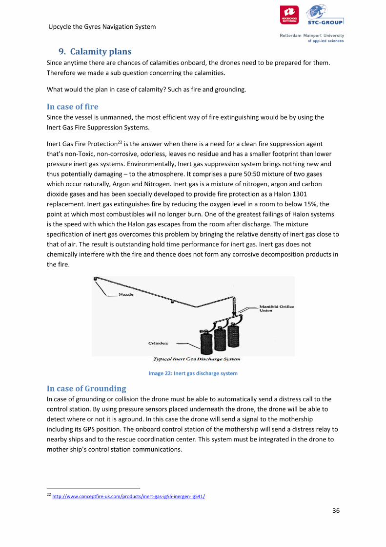
In case of fire Since the vessel is unmanned, the most efficient way of fire extinguishing would be by using the
Inert Gas Fire Suppression Systems.
Inert Gas Fire Protection22 is the answer when there is a need for a clean fire suppression agent
that’s non-Toxic, non-corrosive, odorless, leaves no residue and has a smaller footprint than lower
pressure inert gas systems. Environmentally, Inert gas suppression system brings nothing new and
thus potentially damaging – to the atmosphere. It comprises a pure 50:50 mixture of two gases
which occur naturally, Argon and Nitrogen. Inert gas is a mixture of nitrogen, argon and carbon
dioxide gases and has been specially developed to provide fire protection as a Halon 1301
replacement. Inert gas extinguishes fire by reducing the oxygen level in a room to below 15%, the
point at which most combustibles will no longer burn. One of the greatest failings of Halon systems
is the speed with which the Halon gas escapes from the room after discharge. The mixture
specification of inert gas overcomes this problem by bringing the relative density of inert gas close to
that of air. The result is outstanding hold time performance for inert gas. Inert gas does not
chemically interfere with the fire and thence does not form any corrosive decomposition products in
the fire.
Image 22: Inert gas discharge system
In case of Grounding In case of grounding or collision the drone must be able to automatically send a distress call to the
control station. By using pressure sensors placed underneath the drone, the drone will be able to
detect where or not it is aground. In this case the drone will send a signal to the mothership
including its GPS position. The onboard control station of the mothership will send a distress relay to
nearby ships and to the rescue coordination center. This system must be integrated in the drone to
mother ship’s control station communications.
22 http://www.conceptfire-uk.com/products/inert-gas-ig55-inergen-ig541/

Upcycle the Gyres Navigation System
37
Conclusion The inert gas fire extinguishing system is already used on several seagoing vessels and is a user’s
friendly and safe system to be used on the drones. The system is proven to extinguish fire rapidly
without damaging the instruments onboard. The IDLS system makes it possible for the drone to
automatically send VHF data signals. These calls are then relayed by the mothership. In case of
grounding or collision the drone must be able to automatically send a distress call to the control
station. By using pressure sensors placed underneath the drone, the drone will be able to detect
where or not it is aground. In this case the drone will send a signal to the mothership including its
GPS position.

Upcycle the Gyres Navigation System
38
Project Conclusion In this project we presented the Upcycle the Gyres navigation system. The motivation for this project
was to provide a navigation system for fully automated drone for the recovery of plastics waste in
the ocean (gyres). We discussed the motivation for overcoming limitations in 8 sub questions. The
main contribution of this project is the interview made with the companies.
How will the on board control station communicate to the drone, so that the drone could be
operated manually if required?
For the use of ship-shore communication, satellite systems like the Integrated Data Link System or
the ORBIT Maritime VSAT AL-7109 would probably be the best choice. These systems can also be
used to communicate to the drones. As a back-up for intership communication, which is ship to ship,
the MORSE system can be used, because data is transmitted through a VHF-band. To reach the
drones that are out of normal VHF-range, the mother ship can use multiple RipEX system interaction.
Navigation via Signals of Opportunity can work as a back-up for the GPS aboard the drones and the mothership, so the drones can be located anywhere on the sea and ensure safe navigation Is this control station the only one that can navigate the drone? Or could we make a system at
which external users (internet users) can navigate the drone while it's being monitored by the
onboard control station? In this case the onboard control station can overwrite external users at
any time.
The drone may be navigated by the onboard control station of the mothership or by an additional
software system. In the beginning the intention behind the additional software was to use it for
commercial gaming by external users. Researches and consulting had shown that the system may
not only be used for gaming, but also or other purposes, such as transmitting data systematically or
research concerning maritime pollution
How must the drone navigate through a giant patch of floating waste? By an advanced planned
route to navigate between the coordinates of the waste patch, for example an in a spline
movement or navigating from one coordinate to another?
The best way to systematically recover the waste in the ocean is by using coordinates of the debris
patches. These coordinates strongly depends on the directions of wind and currents. The Wave
Glider will provide the Onboard Control Station with the information about the coordinates of the
debris patches and the directions of wind and currents. This way the Onboard Control Station can
navigate the drone on the right course through the garbage patch. The drone will sail in the opposite
direction of the current and with the same speed as the current. The drone will then stay in one
place while the marine debris flows to the drone.

Upcycle the Gyres Navigation System
39
How is the drone going to identify whether it’s recovering waste or its just navigating through
clean water?
When the wastes float inside the drone the rollers inside will pick them up. The infrared system is
able to detect the difference between plastics and other materials. After that the infrared scanner
uses air pressure to separate the plastics from other materials. Then the infrared system (appendix I)
will separate the organic material from the plastics.
How is the vessel going to keep up with the Regulations for Preventing Collisions at Sea? Such as
avoiding other vessels.
The drones must be provided with a system that sends signals that tell other ships that it is a
hampered vessel and the done must also show day marks and light signals according to the
Regulations for Preventing Collisions at Sea. The drone must show three marks in line ball-diamond
shaped-ball during the day and light signals at night. At night the lights should be on top and bottom
a red light, with in the middle a white light.
How is the drone going to be guided though berthing near the facility?
The drone will be guided by a laser guided berthing system and a vacuum mooring system. These
systems are proven to be successful and are nowadays used in different harbors such as Canada St
Lawrence Seaway, Australia, New Zealand, Oman and in the Panama Canal, in the near future this
system will also be used in three high frequency fast ferry routes in Denmark. These installations can
easily be installed along the side of the mothership, which makes these systems suitable for this
project. This is taken into consideration that the drones must be able to berth and moore fast, easily
and safely when they are unloading at the mothership.
In case of blackout, what would happen to the vessel?
In case of a blackout the drone will use electric energy from an independent sets of power packs
used only in case of emergency. According to the requirements the emergency backup system must
be independent from the main system, this means a complete wiring installation for the emergency
system that does not rely on the main installation. The emergency backup system will supply limited
electric energy, this in order to supply the most important components and instruments with electric
energy, e.g. navigation instruments and communication instruments.
What would be our plan in case of calamity? Such as fire, grounding, etc.
The inert gas fire extinguishing system is already used on several seagoing vessels and is a user’s
friendly and safe system to be used on the drones. The system is proven to extinguish fire rapidly
without damaging the instruments onboard. The IDLS system makes it possible for the drone to
automatically send VHF data signals. These calls are then relayed by the mothership. In case of
grounding or collision the drone must be able to automatically send a distress call to the control
station. By using pressure sensors placed underneath the drone, the drone will be able to detect
where or not it is aground. In this case the drone will send a signal to the mothership including its
GPS position.

Upcycle the Gyres Navigation System
40
The conclusion is that the upcycle the gyres navigation system should use multiple communication
systems that could both communicate with the mothership as with the outer world. For this reason
the drones should communicate with IDLS, NAVSOP and MORSE system.
The drones should use as least energy as possible. The drones should use the currents of the gyres as
an advantage by navigating against the currents. By countering the currents the plastic garbage
would flow into the plastic identification system of the drones.
In case of calamity the drones must be equipped with: an inert gas installation in case of fire, battery
power packs in case of blackout and pressure sensors in case of grounding. The mothership should
be provided with a mooring system for the drones to unload their garbage and an Onboard Control
Station for supervising and keeping lookout in case anything goes wrong.
Recommendations Recommendations are that Upcycle the Gyres should use this report as a first step for further
research. In this research there was proven that the technologies for this navigation system are
already available. However the financial costs for the systems referred to in this report are not yet
investigated.
Therefore we recommend a follow up research about the costs and implementation of the systems
referred in this report. This way Upcycle the Gyres will get to known if they are able to finance and
execute this project.
Taking into consideration that the navigation of a drone uses allot of data transfer, which the costs
nowadays are very high. Upcycle the Gyres should approach governments for a possible fund,
because this project is eco-friendly and it brings a solution for a global issue. Also Upcycle the Gyres
can approach other companies to help finance this project, because this project gives the companies
a green image, which is beneficiary for each company.

Upcycle the Gyres Navigation System
41
References Upcycle the Gyres
1. http://www.upgyres.org
Integrated Data Link System
2. http://www.commtact.co.il/?CategoryID=235&ArticleID=195 Navigation via Signals of Opportunity
3. http://www.newscientist.com/blogs/onepercent/2012/06/gps-jammed.html ORBIT Maritime VSAT AL-7109
4. http://www.orbit-cs.com/communications-and-entertainment-antenna The MORSE system
5. http://www.racom.eu/eng/references/radio-modem-maritime.html 6. http://www.racom.eu/eng/products/radio-modem-ripex.html#features
7. http://www.vstep.nl/
The definition of a gyre
8. http://peswiki.com/index.php/Directory:Ocean_Trash_Vortexes_%28Gyres%29
9. Lavender Law, Kara; S. Moret-Fergusen, N. Maximenko et al. (2010). "Plastic accumulation in the north atlantic subtropical gyre". Science 329 (5996): 1185-8 http://www.sciencemag.org/content/329/5996/1185.full
10. R. Jude Wilber; “Plastic in the North Atlantic” ;The Graduate http://5gyres.org/media/Plastic_in_the_North_Atlantic_OCEANA_1987.pdf
11. Guhin, Scott, et al. "The South Atlantic Current." Ocean Surface Currents. NOPP; CIMAS; RSMAS; HYCOM consortium, 2003. Web. 21 Oct. 2009. http://oceancurrents.rsmas.miami.edu/atlantic/south-atlantic.html
12. A Sea of Change: Biogeochemical Variability in the North Pacific Subtropical Gyre. Springer. 1999
13. http://liquidr.com/technology/wave-glider.html
14. http://www.omrin.nl/Over_Omrin/Wat_doen_we/Nascheiding.aspx
15. http://www.clrwtr.com/PDF/Banner/Banner-MINI-BEAM-Clear-Plastic-Detection.pdf
16. http://www.spacedaily.com/reports/Northrop_Grumman_Awarded_Unmanned_Surface_V
essel_Contract_From_DARPA_999.html
17. http://www.trelleborg.com/en/Marine-Systems/Products-And-Solutions/Docking-and-Mooring/Docking-Aids/SmartDock/
18. http://www.accessdata.fda.gov/scripts/cdrh/cfdocs/cfStandards/detail.cfm?standard__identification_no=29910

Upcycle the Gyres Navigation System
42
19. http://www.ttsgroup.com/Articles/Vacuum-based-automooring/
20. http://www05.abb.com/global/scot/scot293.nsf/veritydisplay/82b8e284d5fdc935c1257a8a
003c26a4/$file/ABB%20Generations_22%20High%20capacity%20battery%20packs.pdf Ventilation and Cooling Requirements for ICT rooms
21. http://www.terena.org/activities/campus-bp/pdf/gn3-na3-t4-ufs108.pdf 22. http://www.conceptfire-uk.com/products/inert-gas-ig55-inergen-ig541/

Upcycle the Gyres Navigation System
43
APPENDIX I: During the visit at Onrim in Oudehaske, we got a tour through the company. First they showed us a
PowerPoint presentation of the company and their sorting system. After that they showed us the
sorting system, with its different phases and sorting technics (see PowerPoint). After that we got to
see the REKAS-system.
How is the regular trash sorted?
The trash comes in and goes through the first drum sieve. In the drum sieve the trash gets whirled
around. Just like clothing in a washing machine. In the drum are holes of 200mm. Large pieces of
trash comes out at the end of the drum, while the smaller pieces of trash fall through the holes and
are transported to the second drum sieve. In the second drum sieve trash is sorted the same as in
the first drum sieve. At the end of the second drum sieve the plastic trash goes through an infrared
scanner. The scanner scans the passing trash and sorts out anything at aren’t plastics, by using
airstreams. After each drum sieve, a magnet sorts out metallic parts that remain in the trash. The
plastic that is sorted out goes on through the REKAS-system.
Image 23: Nascheider installation

Upcycle the Gyres Navigation System
44
How does the REKAS-system works?
REKAS is an abbreviation Recycling van Kunststoffen door Middel van Automatische Sortering. The
purpose of REKAS is to separate the different types of plastic. The plastics roll onto the ballistic
separator, which separate the different types of plastic by weight. The light plastics roll to the top of
the separator, while the heavy plastics roll to the bottom of the separator. At each end the plastics
fall onto a conveyer belt and are separated by an infrared scanner.
Image 24: REKAS-system
According to Mr. Koopmans (the expert) it is possible to use both systems onboard of a ship. But
systems have to be decreased in size, which could bring extra costs. It is possible to sort out plastic
by using the REKAS-system but the infrared scanner on the system can’t detect micro plastic. On top
of that it is not profitable to sieve out micro plastic, because the expenses to find and collect are
greater than the benefits. “A possible solution to collect micro plastic, is to filter the plastic out of
the sewerage system, before it comes into the sea”: Mr. Koopmans.

Upcycle the Gyres Navigation System
45
Appendix II:
Visit at Imtech: The visit at Imtech was a real eye-opener. The specialist was very acquainted with the methods for
cleaning the ocean. He told us about the new “waveglider drones”. And about how it was impossible
to clean the ocean if the drone uses too much energy. The energy in the wave glider drone is
obtained by its solar panels. It uses the energy supply for the onboard sensors. These sensors can be
sensors for density, so if there are plastics floating nearby they can be detected. Also currents and
heights of waves can be detected, so that we could know where the plastics are floating to, and we
might collect data about where the plastics stack.
This is of great importance for the project because with this information the mothership could be
able to navigate to the accumulated stacks of plastic waste.
The other great idea was about the use of seaweeds. The plantations are used to make oil from. The
plantations also filter the oceanic waters, if there are plastics in the waters, those will stay in the
seaweed filters. By using the methods of OMRIN about separation of plastics from organic waste,
there might be a possibility to use those plantations as ocean cleaners.
We also asked some questions about other subjects in our project.
The use of communication: The specialist said that it would be impossible to use the drones for playable reasons, an Internet
connection between the drones and the shore is too expensive and the connection would be bad.
The simplest and most cheap possibility would be a radio-connection.
A possible solution could be a radio tower on the mothership. If the drones stay near the
motherschip they could be in constant connection with the mothership. But even then the drones
will use a lot of energy.
Drones with a broadband connection to the shore are excluded.
The navigation: The systematic navigation of the drones is a way to navigate through the waters, but the problem is
not how to navigate, but how to get to all the plastics. The ocean has a huge amount of waters. If all
the water needs to be systematically cleaned it would need millions of drones, this would be too
expensive. It would be a better solution to find the places where the waste accumulates, and then to
send the drones there.
If those places are not found, the drones need to filter too much waters in order too get just a little
piece of plastic.
Colregs: Normally ships that are performing work notify that by showing a ball on deck, they are not able to
navigate well. Therefore other ships give away.
Drones are not able to navigate well so might need the same treatment.
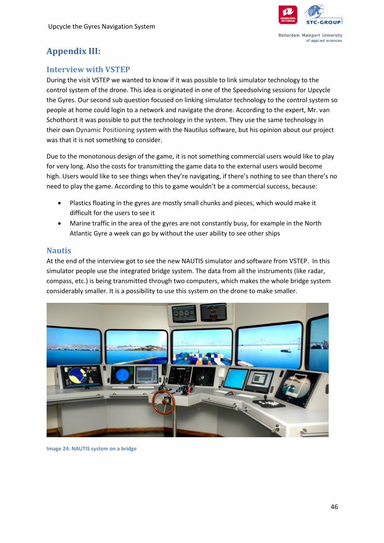
Upcycle the Gyres Navigation System
46
Appendix III:
Interview with VSTEP During the visit VSTEP we wanted to know if it was possible to link simulator technology to the
control system of the drone. This idea is originated in one of the Speedsolving sessions for Upcycle
the Gyres. Our second sub question focused on linking simulator technology to the control system so
people at home could login to a network and navigate the drone. According to the expert, Mr. van
Schothorst it was possible to put the technology in the system. They use the same technology in
their own Dynamic Positioning system with the Nautilus software, but his opinion about our project
was that it is not something to consider.
Due to the monotonous design of the game, it is not something commercial users would like to play
for very long. Also the costs for transmitting the game data to the external users would become
high. Users would like to see things when they’re navigating, if there’s nothing to see than there’s no
need to play the game. According to this to game wouldn’t be a commercial success, because:
Plastics floating in the gyres are mostly small chunks and pieces, which would make it
difficult for the users to see it
Marine traffic in the area of the gyres are not constantly busy, for example in the North
Atlantic Gyre a week can go by without the user ability to see other ships
Nautis At the end of the interview got to see the new NAUTIS simulator and software from VSTEP. In this
simulator people use the integrated bridge system. The data from all the instruments (like radar,
compass, etc.) is being transmitted through two computers, which makes the whole bridge system
considerably smaller. It is a possibility to use this system on the drone to make smaller.
Image 24: NAUTIS system on a bridge

Appendix IV:

Upcycle the Gyres Navigation System
1
Appendix V