updated manual# 10961999 rev c - chart industries,...
TRANSCRIPT

230/265/300/450/700/1000/1500
Manual #10961999
Operating Manual

TABLE OF CONTENTS_______________________1
2
1 Preface 2 2 Introduction 3 3 Theory of Operations 4
Liquid Withdrawal 4 Gas Withdrawal 5
4 Installation 6 Common Codes and Standards 6
Tools and Supplies 7 Hardware 7
Additional Required Supplies 8 Hoses and Lines 8 Filling Procedures ASME_______________ 10 Filling Procedures DOT ________________ 11 5 Cyl-Tel and Telemetry_____ 14 6 Safety 19 7 Illustrations & Parts Listings 20
230/265 20 Configure to Order Overview _ 24 230/300/450/700 30 1000_______________________________36 1500HP 42 1500VHP 46
8 Warranty 50 9 Specifications 51 10 Troubleshooting___________________________52 11 Additional References______________________58 Changing Services ____________________58 Associated Manuals___________________58 Revision Log Description
Rev A (06/20/01)
Correct part number on pages 20 and 21, item number 8 from 10746447 to 11488591
Rev B (04/02/02)
Updated Perma-Cyl line for configured to order.
Rev C (10/1/03)
General Update
Any comments or suggestions about this manual should be mailed in writing to: CHART Inc. 1300 Airport Drive Ball Ground, GA 30107 You may also reach us at Phone: 800-400-4683 Fax: 952-758-8293

INTRODUCTION 2
3
The Perma-Cyl is an innovative design evolving from proven technology we have been using for years on our liquid cylinders. What makes the Perma-Cyl design revolutionary is the fast fill capability, no loss/low loss fill with automatic fill termination, extended hold time and telemetry compatibility. When filled by an ORCA truck, the Perma-Cyl vessel is designed to have an actual fill-time of three minutes or less (smaller models) with zero losses under normal conditions. The vessel will allow liquid to be held for long periods without venting, limiting product losses during periods of nonuse. The new Cyl-Tel gauge features an accurate user-friendly display and is “telemetry ready” to connect to Chart’s phone line, cellular or satellite systems. This manual is a documentation of Perma-Cyl cryogenic liquid cylinders by Chart Industries. Its purpose is to provide the users with the necessary information for the operation and the maintenance of the following tanks; Perma-Cyl 230/265 MP/HP LCCM DOT, Perma-Cyl 230/300 MP/HP, Perma-Cyl 450MP/HP/VHP, Perma-Cyl 700 HP, Perma-Cyl 1000 HP/VHP, and Perma-Cyl 1500 HP/VHP. The manual is divided into following sections. Section 2 - Introduction to Perma-Cyl liquid cylinders. Section 3 - Theory of operations. Section 4 – Perma-Cyl installation guidelines that should be followed. Section 5 – Instructions for the Cyl-Tel level gauge and Telemetry. Section 6 - Safety procedures needed in the operation of the tanks. Section 7 - The plumbing illustrations and the part listings. Section 8 - The Warranty on the Perma-Cyl products. Section 9 - Specifications for the Perma-Cyl tanks. Section 10 – Perma-Cyl Troubleshooting. Section 11 – Additional References.

THEORY OF OPERATIONS___________________3
4
1 INITIAL INSPECTION
Upon receipt of the Perma-Cyl, remove the protective wrapping and inspect for the following: 1. Any shipping damage to the Perma-Cyl
including dents, cuts, and broken or bent plumbing components. Report damage to the shipping company immediately.
2. Warranty card, Operator Instructions Sheet, and Users Manual.
3. The Perma-Cyl is shipped with low purity Nitrogen gas. Purging is necessary prior to filling.
1.1 GENERAL
The Perma-Cyl model liquid cylinder is designed to, store and deliver liquid oxygen, nitrogen or argon as a cryogenic liquid. The Perma-Cyl can build and maintain pressure from the automatically regulated pressure building circuit. A continuous liquid or gas flow can be provided from these cylinders. Regardless of size, all Perma-Cyls operate on the same principals of operation.
C A U T I O N
Only use replacement equipment, which is compatible with liquid oxygen and has been cleaned for oxygen use. Do not use regulators, fittings, hoses, etc., which have been previously used in compressed air service. Similarly, do not use oxygen equipment for compressed air. Failure to comply with these instructions may result in serious damage to the liquid cylinder and personal injury.
1.2 FILLING PROCEDURES
During a first fill, only fill the vessel to 75% full to allow liquid expansion experienced with a new “hot” tank. Each fill there after can be filled to 100% full. See ORCA Manual for Procedures
1.3 LIQUID WITHDRAWAL
Cryogenic liquid can be pressure transferred from the liquid cylinder to other cryogenic equipment that operates at a lower pressure than the liquid cylinder. To make a liquid transfer, follow this procedure:
C A U T I O N
If liquid can be trapped in the transfer system, a suitable relief valve must be installed to prevent over pressurization.
Before making a liquid transfer be sure that protective eyeglasses and gloves are being worn. If the transfer is being made to an open top vessel, the transfer pressure should be as low as possible and a phase separator should be used to eliminate splashing and hose whip.
1. Connect the transfer hose to the liquid valve connection of the cylinder.
2. Connect or place the other end of the hose onto the inlet of the cryogenic equipment that will receive liquid. Atmospheric dewars are filled with a phase separator mounted to the open end of the hose.
3. Refer to the receiving equipment manual for procedures to open the fill valve and vent valve of the receiving equipment.
4. Open the liquid valve. This valve can be adjusted to obtain the proper liquid flow rate.
5. The pressure building valve can be opened to build and maintain a higher cylinder pressure during liquid transfer.
6. When the transfer is complete, close the receiving equipment’s valve. Close the liquid valve and relieve pressure from the hose.

THEORY OF OPERATIONS 3
5
BACK of an ORCA TRUCK
7. Disconnect or remove the hose from the receiving equipment.
1.4 GAS WITHDRAWAL
The Perma-Cyl will deliver gas at various flow rates and temperatures for different applications. The equipment that is being supplied gas from the Perma-Cyl controls the flow rate. Higher flow rates may provide very cold gas that could damage the equipment to which they are attached. To supply gaseous product, follow this step by step procedure.
C A U T I O N
Pressure should be allowed to escape from the transfer hose before it is completely removed. A hose drain and relief valve should be installed in all transfer lines.
1. Connect the proper regulator to the liquid cylinder's gas use outlet.
2. Connect the proper hose between the final line regulator and the receiving equipment.
3. Open the pressure building valve. 4. Allow pressure (refer to gauge) to build
to the operating pressure. 5. Open the gas use valve. 6. Adjust the gas use regulator for the
proper delivery pressure. 7. When the gas delivery is completed,
close all valves.
C A U T I O N
All valves on an empty Perma-Cyl should always be kept closed to protect the inner vessel and plumbing from being contaminated.
The operator should review the safety precautions found in Section 1 Initial Inspection, 1.1 General before conducting a gas or liquid withdrawal operation. Protective eyeglasses and gloves should always be worn. At low flow rates, the Perma-Cyl Series is capable of delivering warm gas through the line regulator. As the flow rate increases, the temperature of the gas decreases. If the cold temperature becomes a problem at a desired flow rate, an external vaporizer can be added. Attach this vaporizer directly in series with the gas use connection and place the line regulator at the exit of the vaporizer.
Sept 2000 Page 23

INSTALLATION 4
6
INSTALLATION COMMON CODES AND STANDARDS The installer will need to find out what local city ordinances and which rules they are mandated to follow. One of the following standards may apply; Uniform Fire Code (UFC), Compressed Gas Association (CGA), and the National Fire Protection Association (NFPA, for oxygen only).
1. Uniform Fire Code standards ♦ Article 75 ♦ Flammable Cryogenic fluids ♦ Inert Cryogenic fluids ♦ Oxidizer Cryogenic fluids ♦ Article 80 ♦ Section 311 states cryogenic storage
indoors must be less then 1000 Lbs. water capacity or less, equivalent to a 450 Liter tank
2. Compressed Gas Association ♦ Pamphlet P-9 Inert Gases ♦ Section 9 & 10 storage liquid cylinders
capacity indoors ♦ No capacity given but list approximately
30 gallons ♦ Must be well ventilated ♦ Section 12 Storage Bulk capacity
indoors ♦ See Pamphlet P-18 ♦ Pamphlet P-18 Bulk Inert Gases ♦ Section 5.2 Indoor storage ♦ No capacity given ♦ Must be well ventilated ♦ Fill, full try cock, vent, and relieves must
be piped outside ♦ Warning signs are required ♦ Pamphlet G-4 Oxygen Gases
♦ Section 6 Oxygen storage and handling safety
♦ Section 7 Oxygen storage ♦ Capacity of 45 gallons ♦ Area must be well ventilated preferable
outside ♦ Keep away from flammable materials ♦ Section 9 Bulk Oxygen Systems ♦ No capacity listed
Refers to NFPA 50 for direction National Fire Protections Association
♦ NFPA 50 Bulk Oxygen Systems ♦ Section 1-3 Bulk Oxygen Systems are
658 liters (which includes all tanks in system) and larger
♦ Chapter 2 locations for bulk oxygen tanks
♦ Section 2-1.1 Storage can be outside above ground or inside a non-flammable or limited combustible building (see NFPA 220 for description of building requirements)
♦ Area must be adequately vented and used exclusively for that purpose
♦ Section 2-2 list distances for special items
♦ Section 3-5.8 area must be marked with permanently marked placards
Note: Items listed above are only paraphrased and are only to be used as a reference to find sections of the listed codes which apply to the storage of cryogenic tanks. All items listed in the codes must be followed and adhered to in order to comply. There maybe other codes which apply to your installation. Check with your local authorities
REGULATIONS VARY IN EVERY PART OF THE COUNTRY. ALWAYS CONSULT LOCAL CODES!

INSTALLATION 4
7
INSTALLATION TOOLS AND SUPPLIES For more information please refer to the Perma-Cyl Installation manual PN 11630833
GENERAL
Installation of the Perma-Cyl System requires that certain tools and supplies are available. For simple and economical installations, the following supplies and tools should be maintained, however, not all installations will require them.
INSTALLATION SUPPLIES
♦ Silicone Sealant (clear and white) ♦ 2” PVC Pipe and Elbows ♦ ¼” Plastic Screw Anchors ♦ ¼” x 1” Self-Tapping Screws ♦ 9” Cable Ties ♦ PVC Cement ♦ Duct Tape ♦ Teflon Tape ♦ PVC Flanges ♦ Chalk or Marker ♦ Leak Check Solution
INSTALLATION HARDWARE
Hardware MVE P/NPerma-Cyl Wall Box 11045036Perma-Cyl Wall Box AR QD 11074494Perma-Cyl Wall Box Inert Flare 11074486Perma-Cyl Wall Box N2 QD 11074478Perma-Cyl Wall Box O2 Flare 11074523
Warning: When using the following tools, suitable eye and ear protection must be worn. Failure to do so could result in serious personal injury.
INSTALLATION TOOLS
Electric Hammer Drill: Used for drilling holes and chiseling brick. Accessories include:
♦ ¾” x 21” Scaling Chisel ♦ 2 ½” Core Bit ♦ 1” x 21: Drill Bit (Masonry) ♦ ¼” x 13” Masonry Bit ♦ ½” Masonry Bit
7 ¼” Builder’s Circular Saw: Used for scoring brick and cutting wood exteriors. Accessories include:
♦ Masonry Cutoff Wheel ♦ Combination Blade
Reciprocating Saw: Used for cutting through wood walls. Accessories include:
♦ ¼” and 3/8” Masonry Bits ♦ Set of Twist Drills ♦ 2 ½” Hole Saw
Oxy-Acetylene Torch: Used for cutting rebar in poured concrete walls and floors.

INSTALLATION 4
8
Note: Please refer to Perma-Cyl Installation Manual (P/N 11630833) for more detailed installation instructions.
ADDITIONAL REQUIRED SUPPLIES
♦ Hand Truck with Strapping Attachment ♦ Torpedo Level ♦ Carpenter Square ♦ Extension Cord ♦ Oetiker clamp Pliers ♦ Step Ladder ♦ Caulk Gun ♦ Assorted Hand Tools ♦ Flashlight
INSTALLATION OF HOSES AND LINES
GENERAL
Running the liquid fill hose and vent hoses from the fill box to the tank, will most likely be done differently at each location. By following the basic rules and guidelines listed below, the lines can be run easily and as simply as possible. A typical wall box installation is diagrammed below. Note the guidelines for piping to be used.
SCHEMATIC
CHECK VALVE
LIQUID VALVEVENT VALVE
FILLCONNECTION1/2" * 45° FLCGA 295
CHECK VALVE
**DASHED LINES SUPPLIED BY OTHERS
1/2" ID5/8 ODCOPPER MIN
MANUAL VENTEXHAUST
1/2" FPT(3 PLCS)
PRESSUREGAUGE
SAFTEY VENTEXHAUST
5/8" ID3/4 ODCOPPER MINFOR AUTOSHUT-OFF
FILL
SAFETY
VENT
TYPICALPERMA-CYL
TYPICALWALL BOX
SOFT COPPER W/6" BEND RADIUS (MIN BENDS).20 FT. MAX.BARE PIPE FROM TANK TO WALL BOX (KEEP MINIMUM).INSULATE BARE PIPE W/AIR CONDITIONING FOAM.FOR RUNS GREATER THAN 20 FT USE PYTHON PIPE.5/8"ID MIN FOR FILL LINE.1/2" ID MIN FOR SAFETY AND VENT.
INSTALLATION GUIDELINES
RELIEF VALVE
VENT VALVE
GAS USE VALVE
BURST DISK

INSTALLATION 4
9
LINE CONNECTION TO FILL BOX PANEL
1. Fasten NPT connection on vent hose to the
NPT fitting on the back of the control panel. 2. Fasten NPT connection on fill hose to the
NPT fitting on the back of the control panel. 3. Fasten NPT connection on safety vent to the
NPT connection on the back of the wall box. 4. Feed all lines back into building while
pushing panel back into the fill box. 5. Loosely fasten panel into box (it will be
removed for pressure checking later).
SLAB BUILDINGS
The tank distance from the outside box will vary from 12 inches to 15 running feet. The lines are generally attached to the wall by conduit straps every 18 inches. It is not necessary to run lines through a conduit sleeve, but if lines are exposed to a high traffic area and it is apparent lines may be damaged, it would be best to run them through a conduit sleeve for protection. The sleeve material generally used is 2” PVC piping. 1. Feed the liquid fill and vent hoses through
PVC wall flange (on inside wall, if used). 2. If the lines are being run without sleeving
material, proceed to step 8. 3. If sleeving material is being used, size and
cut the sleeve material to the proper length with a 90-degree elbow toward the wall flange.
4. Feed the lines through PVC sleeve and elbows.
5. Bond the sleeve and elbow together, only if necessary, with PVC glue. Bond as little as
7. Run sleeving conduit to tank. 8. Attach PVC sleeve to wall with conduit straps. Run lines to tank. Attach lines to wall with conduit straps every two to three feet.
BOLTING TO FLOOR
The Perma-Cyl tank is equipped with a flange on the bottom that has four holes for attachment. To ensure a safe environment, the tank must be bolted to the floor. 1. Place tank in position with gauges
facing forward. 2. Mark holes on floor, move tank. 3. Drill holes using ½” masonry bit. 4. Blow out dust and insert masonry
anchors. 5. Move tank back into position over
holes and install lag bolts. 6. Tighten bolts.

INSTALLATION 4
10
CONNECTING LINES TO THE STORAGE TANK 1. Connect liquid fill hose to inlet NPT fitting on the tank. 2. Connect vent line hose to vent NPT fitting on the tank, open the vent valve. 3. Connect safety vent line to NPT fitting on tank (Safety Vent Assembly needed). 4. Connect delivery line to the gas use flare fitting on the tank.
Prior to installing the lines on the tank, any residual pressure should be vented off. This is done by opening the vent line.
FILLING PROCEDURES, ASME:
Please refer to the ORCA Manual for correct filling procedures for a Perma-Cyl.
ORCA TRUCK

INSTALLATION 4
11
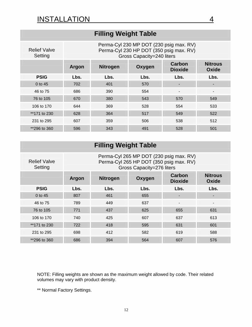
FILLING PROCEDURES, DOT: The Perma-Cyl 230, 265 and 450DOT are regulated by the Department of Transportation(US DOT) for transporting liquid oxygen, nitrogen, argon, carbon dioxide, and nitrous oxide. The filling of these liquid cylinders must be done by product weight. This will allow enough gas space above the liquid to keep the liquid cylinder from becoming liquid full if its pressure rises to the relief valve setting. The filling weight table indicates the correct product weight for the various relief valve settings. The standard relief settings are 230 psig (15.9 BAR), 350 psig (24.1 BAR), and 550 psig (37.9 BAR). Filling can be accomplished by either pressure transfer or pump fill. The following procedure is for a pressure transfer fill. 1. Sample the residual gas that is in the cylinder. Purge the cylinder if necessary to insure the proper purity. 2. Place the cylinder on the filling scale. Record the weight. Compare this weight to the registered tare weight on the data plate. The difference is the weight of the residual gas. 3. Connect the transfer hose to the fill fitting. Record the new weight. The difference between this weight and the initial weight is the weight of the transfer hose. 4. To determine the total filling weight add the tare weight of the cylinder, the hose weight and proper filling weight from the table. The table indicates the product across the top and the relief valve pressure down the side. Connect the two columns to find the proper weight. Example: Perma-Cyl 230, Nitrogen at 350 psig (24.1 BAR) has a product weight of 343 pounds. 5. Open the cylinders’ vent and liquid valves. Open the transfer line shut-off valve to begin the flow of product. 6. When the scale reads the calculated total filling weight, turn off the liquid valve on the cylinder. Close the vent valve. 7. Close the transfer line shut-off valve and relieve the pressure in the transfer line. Remove the transfer line. Remove the cylinder from the scale. NOTE: The Perma-Cyl DOT models can also be filled by the ORCA and will automatically shut off at the correct fill level.
INSTALLATION 4
12
NOTE: Filling weights are shown as the maximum weight allowed by code. Their related volumes may vary with product density. ** Normal Factory Settings.
Filling Weight Table
Relief Valve
Setting
Perma-Cyl 230 MP DOT (230 psig max. RV) Perma-Cyl 230 HP DOT (350 psig max. RV)
Gross Capacity=240 liters
Argon Nitrogen Oxygen Carbon
Dioxide Nitrous Oxide
PSIG Lbs. Lbs. Lbs. Lbs. Lbs. 0 to 45 702 401 570 - -
46 to 75 686 390 554 - -
76 to 105 670 380 543 570 549
106 to 170 644 369 528 554 533
**171 to 230 628 364 517 549 522
231 to 295 607 359 506 538 512
**296 to 360 596 343 491 528 501
Filling Weight Table
Relief Valve
Setting
Perma-Cyl 265 MP DOT (230 psig max. RV) Perma-Cyl 265 HP DOT (350 psig max. RV)
Gross Capacity=276 liters
Argon Nitrogen Oxygen Carbon
Dioxide Nitrous Oxide
PSIG Lbs. Lbs. Lbs. Lbs. Lbs. 0 to 45 807 461 655 - -
46 to 75 789 449 637 - -
76 to 105 771 437 625 655 631
106 to 170 740 425 607 637 613
**171 to 230 722 418 595 631 601
231 to 295 698 412 582 619 588
**296 to 360 686 394 564 607 576
INSTALLATION 4
13
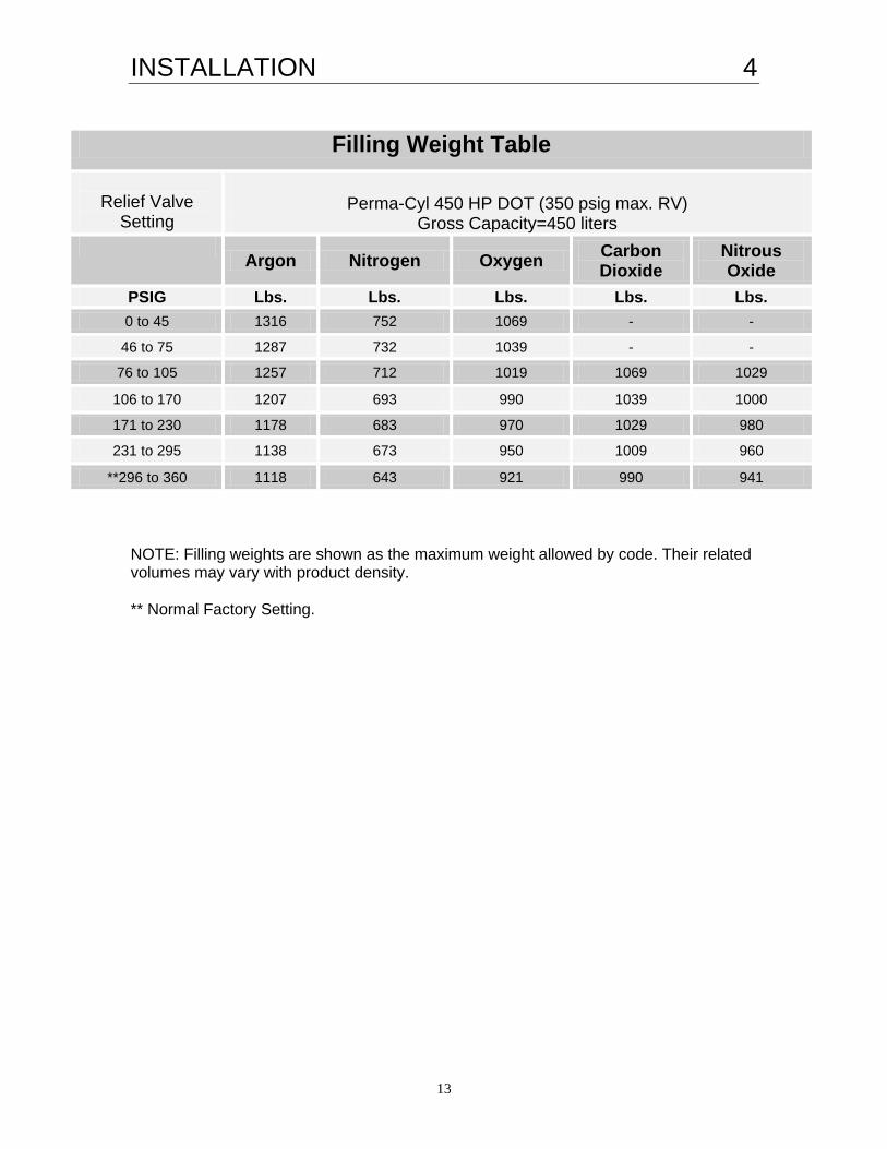
NOTE: Filling weights are shown as the maximum weight allowed by code. Their related volumes may vary with product density. ** Normal Factory Setting.
Filling Weight Table
Relief Valve
Setting
Perma-Cyl 450 HP DOT (350 psig max. RV)
Gross Capacity=450 liters
Argon Nitrogen Oxygen Carbon
Dioxide Nitrous Oxide
PSIG Lbs. Lbs. Lbs. Lbs. Lbs. 0 to 45 1316 752 1069 - -
46 to 75 1287 732 1039 - -
76 to 105 1257 712 1019 1069 1029
106 to 170 1207 693 990 1039 1000
171 to 230 1178 683 970 1029 980
231 to 295 1138 673 950 1009 960
**296 to 360 1118 643 921 990 941

CYL-TEL__________________________________5
14
Cyl-Tel Quick-Start
Instructions
Keypad Operation 1 Single Key Operations. 1.1 ON Key. If you PRESS and HOLD the ON key for 10 seconds the DPG will run through its startup diagnostics tests. When the test is complete, all the red LED’s will turn off unless an alarm is present. 1.2 SELECT Key. This key allows you to select a variable that you have incremented to and advances you to the next field.
1.3 ñ Key. This key allows you to scroll through all available options within a field. 2 Multiple Key Operations. 2.1 Changing Displayed Units. While holding the SELECT and ON keys, press the ñ key to toggle between units. The line of green LED’s on the left side of the box defines which units are being used. When no LED is lit, the display is in “inches of H2O”. 2.2 Setting Alerts. 1) PRESS and HOLD the ñ and SELECT keys for 5 seconds. This will allow you to enter the Alert menu. The first digit of the alarm setting will be blinking. 2) Set the first digit to the desired setting using the ñ key to increment. 3) Use the SELECT key to move to the next digit. Use the ñ key to increment that digit.
4) Continue until Alarms 1 and 2 are set.
2.1 Configure liquid parameters. 1) PRESS and HOLD the ñ and
SELECTkeys for 10 seconds, bypassing the alarm setting menu.
2) Choose the correct liquid type for the tank by incrementing with the ñ key.
3) The SELECT key will move to the tank
configuration menus. 2.4 Configure tank parameters. 1) The tank parameter menus are entered
after the liquid type is chosen. 2) Enter tank length using the ñ key to
set the parameter and the SELECT key to move to the next digit.
3) After the tank length is complete, the
tank diameter should be entered using the ñ and SELECT keys.
4) Choose the tank orientation, horizontal
or vertical, using the ñ key. Press the SELECT key when complete.
5) Bypass the tank calibration menu for the
time being by pressing the SELECT key. (Factory setting : 0)
6) Enter the liquid density pressure using
the ñ key to increment and the SELECT key to finish.
2.1 Calibrating the DPG With the 4-way valve closed, take a reading of % full off the meter. Note: The calibration constant must be changed if the reading is different than 0%.

CYL-TEL 5
15
1) Enter the calibration menu by passing through the tank parameter menus until the calibration constant menu is reached.
2) The calibration constant can be any number between –9 and 9 with each step being approximately 3%. Change the constant from 0, using the ñ key, to achieve the proper reading.
3) Continue until the meter reads 0% full. 4) The 4-way valve should be opened for
operation when complete. NOTE: NEVER leave the 4-way valve closed for extended periods of time.
Reference Information
Display read-outs
Alarms: Alarm 1 ⇐ Alarm 2 ⇐
Liquid Types: Nitrogen ⇐ Oxygen ⇐
Argon ⇐ Carbon Dioxide ⇐ Nitrous Oxide ⇐
Orientations: Horizontal ⇐ Vertical ⇐
Operating pressure: Example⇐ (Select pressure closest to the saturation pressure of liquid for best level of accuracy.)
Calibration: Example ⇐ (Factory setting : 0)
CAUTION: The GAUGE Sensor cannot be exposed to a differential pressure greater than 30PSIG. If exposed to a differential pressure greater than 30PSIG the sensor will be damaged.

CYL-TEL__________________________________5
16
Troubleshooting the Cyl-Tel Gauge
Symptom Possible Cause Remedy Cyl-Tel gauge does not turn on. Battery dead, low, installed incorrectly or
missing. Transformer not plugged in or faulty wiring. Electrical supply circuit breaker tripped. Faulty Cyl-Tel.
Replace battery. Inspect wiring and insure transformer is plugged in. Reset circuit breaker. Replace Cyl-Tel front (p/n 11520503). Call 1-800-400-4683.
Cyl-Tel display is powered, but stays at zero.
No product in cylinder. Four-way valve in “Service” position Four-way valve installed incorrectly Parameters are improperly set Sensor plug not on pins inside Cyl-Tel. Faulty Cyl-Tel.
Ensure there is liquid in cylinder. Turn valve to “Normal” position. See user manual to confirm proper installation Verify EACH parameter setting. The "P" setting as well as the inner dimensions can affect the accuracy of the gauge. Open Cyl-Tel and verify sensor plug is attached to pins. Replace (p/n 11018142). Call 1-800-400-4683.
Cyl-Tel display always reads full. Parameters are improperly set. Faulty Cyl-Tel (Sensor may be damaged).
Verify EACH parameter setting. The "P" setting as well as the inner dimensions can affect the accuracy of the gauge. Replace (p/n 11018142). Call 1-800-400-4683.
Alerts do not operate. Alerts improperly set, or not set. Verify alert settings. Refer to Cyl-Tel manual.
Liquid level oscillates with Four-way valve in either position.
Four-way valve leaking externally Replace Four-way valve. (p/n 11026353)
Liquid level display does not zero when Four-way valve is in “maintenance” position
Calibration point needs adjusting. Four-way valve leaks internally
Adjust "Cal" setting. Refer to Cyl-Tel manual. Replace Four-way valve (p/n 11026353)
Liquid level displayed not accurate. Wrong "P" setting. Calibration point needs adjusting.
Change setting to reflect the proper saturation pressure. Refer to Cyl-Tel manual for details. Adjust "Cal" setting. Refer to Cyl-Tel manual.

CYL-TEL 5
17
Troubleshooting the Cyl-Tel Phone Transmitter
Symptom Possible Cause Remedy
Transmitter will not program. Bad connections. Low battery voltage. Faulty transmitter. Faulty programming cable.
Verify the following: Power connections, J3 connector on trans-mitter to programming cable, and programming cable to receiver card. Battery voltage must be above 9 volts. Try programming a different trans-mitter. If successful, the first trans-mitter is faulty. Replace. Call 1-800-400-4683. Replace cable.
Transmitter will not light up or send No power to transmitter Check 12 VDC power source. "Receiver Adapter Error" The card is busy.
Incorrect setup of software, hardware, the receiver card is not seated in slot, or the receiver card has been damaged.
System will operate normally. Call 1-800-400-4683 for assistance.
Computer will not receive calls. No dial tone. Wrong phone number programmed in transmitter. Wrong phone line plugged into receiver card. Bad phone line.
Verify phone line at receiver card has dial tone - plug line into a phone and listen for tone. Verify number programmed into transmitter. Verify phone line. Check phone line-MUST be analog. Service if necessary.
Receive "Call Overdue" message. Transmitter not installed at customer site, damaged or power interrupted. "Days between test calls" parameter not the same in account setup and transmitter.
Verify transmitter is installed and working properly (test call). If not, make account inactive in the account setup. Make sure these values are the same.
Computer cannot initialize card. Card is not configured correctly, or is not seated properly. Faulty or damaged receiver card.
Verify hardware settings and ensure card is properly seated. Replace. Call 1-800-400-4683.

CYL-TEL__________________________________5
18
Chart Industries offers a full line of telemetry options that help maximize tank performance and minimize delivery costs. A brief overview of the most common systems are summarized below. Phone Reorder System This low cost system consists of a phone transmitter at each Perma-Cyl site and a call receiver box at the distributor. When the vessel reaches each of its two programmable low levels, the phone transmitter calls the distributor’s computer and notifies them of the level. This system requires a phone transmitter at every site and a one-time charge for the software and call receiver but there are no on going costs. OnSite System The OnSite system consists of a daughter circuit board in the Cyl-Tel and a Scout Phone transmitter. The system records liquid levels throughout the day and sends the information once a day to the OnSite website. The data is secure and password protected and can be accessed anywhere an internet connection is available. Tank usage patterns and ORCA routing can be done easily with the OnSite program. Each installation requires a Cyl-Tel daughter board and a Scout phone modem. There is a monthly charge each Scout modem. Cyl-Tel2 – DataQwest System The Cyl-Tel2 is designed to work with the celular telemetry system offered by DataQwest. Each gauge is its own transmitter where it records and transmits data to the DataQwest website daily. Each tank requires a Cyl-Tel2 gauge and there is a monthly charge for the service. NOTE: For each telemetry system, an external power supply is required.

SAFETY 6
19
WARNING Excessive accumulation of oxygen creates an oxygen-enriched atmosphere (defined by the Compressed Gas Association as an oxygen concentration above 23 percent). In an oxygen-enriched atmosphere, flammable items burn vigorously and could explode. Certain items considered non-combustible in air may burn rapidly in such an environment. Keep all organic materials and other flammable substances away form possible contact with oxygen; particularly oil, grease, kerosene, cloth, wood, paint, tar, coal dust, and dirt which may contain oil or grease. DO NOT permit smoking or open flames in any area where oxygen is stored, handled, or used. Failure to comply with this warning may result in serious personal injury.
WARNING Nitrogen and argon vapors in air may dilute the concentration of oxygen necessary to support and sustain life. Exposure to such an oxygen deficient atmosphere can lead to unconsciousness and serious injury, including death.
WARNING * Perma-Cyl 230L - 450L models are suitable to transport full of liquid. * Perma-Cyl 1000L and 1500L models can be transported with no more than 250L of liquid. Transporting these cylinders with more than 250L can damage or destroy the neck tube and support system of the cylinder. * For over-the-road transportation, the pressure in all ASME coded cylinders must be reduced to no more than 22 PSIG. DOT coded cylinders can be transported at service pressure.
WARNING The Perma-Cyl, with its stainless steel support system is designed, manufactured, and tested to function normally for many years of service. MVE does not suggest or warrant that it is ever safe to drop a liquid cylinder or let it fall over in oxygen or any other cryogenic service. In the event a liquid cylinder is inadvertently dropped, tipped over, or abused, slowly raise it to its normal vertical position. Immediately open the vent valve to release any excess pressure in a safe manner. As soon as possible, remove the liquid product from the vessel in a safe manner. If the vessel has been used in oxygen service, purge it with an inert gas (nitrogen). If damage is evident or suspected, return to MVE prominently marked “LIQUID CYLINDER DROPPED, INSPECT FOR DAMAGE”.
WARNING Before removing cylinder parts or loosening fittings, completely empty the liquid cylinder of liquid and release the entire vapor pressure in a safe manner. External valves and fittings can become extremely cold and may cause painful burns to personnel unless properly protected. Personnel must wear protective gloves and eye protection whenever removing parts or loosening fittings. Failure to do so may result in personal injury because of extreme cold and pressure in the cylinder.
WARNING Any welding that is done on the outside of the Perma-Cyl can cause loss of vacuum and will VOID any warranty on the unit.

ILLUSTRATIONS & PARTS LISTING 7
20
PERMA-CYL 230/265 LCCM SCHEMATICS Side View
45 6
7
8
9 15
10
Perma-Cyl 230 HP SB DOT
Perma-Cyl 265 MP RB DOT
Perma-Cyl 230 HP RB DOT
11844137
11511463
11187211
11191674
Perma-Cyl 265 MP SB DOT
C
C
C
C
Perma-Cyl 230 MP SB DOT
Perma-Cyl 230 MP RB DOT
DESCRIPTIONP/N10939687
10896592
REVC
C1
2
3
Parts List
10
Protective Cap
Gas Use Valve
Quick Disconnect
DescriptionItem #*
8
9
Rupture Disc
Primary Relief
*Item #'s correspond with all schematics. See pg 17 for Item #'s 11-14.
Check Valve15
Item #* Description
1 High Phase Port
2 Liquid Use Valve
3 Vent Valve
4
5
PB Valve6
Pressure Gauge7
Roto Cal Gauge
Pump Out Port
Roto Cal Plug/O-Ring
12
14
13
11

ILLUSTRATIONS & PART LISTINGS 7
21
Perma-Cyl 230/265 DOT LCCM Round Base Top View
Perma-Cyl 230/265 DOT LCCM Square Base Top View
910
5
7
8
36414
1
2
15
2
9
10
5
7
8
3
64
14
1
13
12
11
15

ILLUSTRATIONS & PARTS LISTING 7
22
Top View: Cyl-Tel Conversion Kit
LPH
1
2
34
10
12 13
3D View: Cyl-Tel Conversion Kit
SEE NOTE #3 11
9
8
7 65
GPL

ILLUSTRATIONS & PART LISTINGS 7
23
Line Connection: Cyl-Tel Conversion Kit
Parts List: Cyl-Tel Conversion Kit
5
8
3
1
10
2
4) SEAL ALL PIPE FITTING JOINTS WITH TEFLON TAPE.TO SECURE THE CYL-TEL BRACKET.
3) USE THE EXISTING ROTO-CAL PROTECTOR BOLTS AND WASHERSFOR BOTH THE HIGH AND LOW PRESSURE SIDES.
2) CUT THE COPPER TUBING TO FIT BETWEEN THE TUBE FITTINGSIS ORIENTED TOWARD THE LCCM REGULATOR.
1) THE VERTICAL PORTION OF THE MOUNTING BRACKET
NOTES:
10501618
10501571
2910591
2911401
10740213
10501634
2300094
10680388
6910683
11365451
11026353
11823424
11018142
Part Number
311
13
12
2
2
6
8
10
9
7
3
5
4
2
1
1
6
1
1
1
1
3.5 FT
1
1
1
Item# Qty.
FLAT WASHER SS .250
PHPNHMS SS #8-32*3/8
WASHER #8
ELBOW BRS 90D 1/8ODT*1/8MPT
CONNECTOR BRS 1/8ODT*1/4MPT
ELBOW BRS 90D 1/8ODT*1/4MPT
KNUCKLE PLUG 7/8-UNC*1/8NPT
CYL-TEL CONVERSION BRKT.
COPPER TUBING .125 O.D.
4-WAY VALVE LABEL
4-WAY VALVE
CYL-TEL GAUGE ASSY.
O-RING
Description

ILLUSTRATIONS & PARTS LISTING 7
24
Option 01 – CHART Standard Our standard offering.
Option 03 – Component Service Valve Package This package includes isolation valves on all serviceable components including regulators and gauges for easy service and maintenance.
Option 05 – CO 2 Package This package includes all the features that are standard on CHART Beverage Cylinders. Isolation valves are included on all regulators and components. A drain valve is located on the PB circuit for easy cleanout of debris. The cylinder even has the patented Sure-Fill system and standard CO2 Fill Fitting for standardization with the existing CO2 Delivery network.
Option 02 – Gauge Isolation Package This package includes an equalization/service valve
for the differential pressure gauge.
Option 06 – Lynx PB System For increased PB recovery time and increased flow-rates up to 2500 SCFH. The Lynx System also offers isolation valves on all serviceable components.
Option 04 – Liquid Withdrawal Package This package is designed with the liquid use customer in mind. A ball valve is standard on the liquid withdrawal for increased flow-rates while a valved off adjustable low pressure relief maintains low pressure in the cylinder during use.
Option 07 – ZX SUPERCHARGED PB System For the utmost in performance in high pressure, high flow accounts the ZX Supercharger delivers. The ZX uses a high flow pressure building system to attain pressure recovery times as low as 12 minutes and can support withdrawal rates up to 7000 SCFH.
Perma-Cyl 1500 Pressure Recovery
100
150
200
250
300
350
400
450
500
0 50 100 150 200 250 300
Time (min.)
Pre
ssu
re (
psi
)
ZX Lynx Standard
- All tests conducted at indoor ambient conditions ( 70F, 50% RH)
- All tests conducted with a full tank.
The PERMA-CYL® exclusively offers the Configure to Order program that allows you to customize YOUR PERMA-CYL®
specifically for YOUR application.

ILLUSTRATIONS & PART LISTINGS 7
25
Configuration 01
Perma-Cyl 230/300/450/700/1000 MP/HP, 450/1000VHP, 1500 HP
_____________________________________________________________ Configuration 02
Perma-Cyl 230/300/450/700/1000 MP/HP, 450/1000VHP, 1500 HP

ILLUSTRATIONS & PARTS LISTING 7
26
Configuration 03
Perma-Cyl 450/700/1000 MP/HP, 450/1000VHP, 1500 HP
__________________________________________________________ Configuration 04
Perma-Cyl 450/700/1000 MP/HP, 450/1000VHP, 1500 HP

ILLUSTRATIONS & PART LISTINGS 7
27
AD FHG
CEB
Configuration 05 Perma-Cyl 450/700/1000 MP/HP, 450/1000VHP, 1500 HP
___________________________________________________________ Configuration 06
Perma-Cyl 1000VHP, 1500VHP
AD FHG
CEB

ILLUSTRATIONS & PARTS LISTING 7
28
AD FHG
CEB
J
Configuration 07 Perma-Cyl 1000VHP, 1500VHP
Configuration 02 Perma-Cyl 1500 VHP

ILLUSTRATIONS & PART LISTINGS 7
29
Configuration 03 Perma-Cyl 1500 VHP
*Customer specific configurations are available upon request.

ILLUSTRATIONS & PARTS LISTING 7
30
230 ROUND BASE
230 SQUARE BASE
SECTION A-A DETAIL D
SECTION B-B SECTION C-C
6
5 11
Perma-Cyl 230/300-01 Perma-Cyl 230/300-02 Cyl-Tel Chart Standard Gauge Service Valve P/N 11560847 P/N 11525806 P/N 11560855 P/N 11542420 The Chart Standard tank configuration provides The Cyl-Tel Gauge Service Valve tank our customers with the essentials needed for a configuration provides our customers standard cryogenic vessel. with a 4-way valve gauge isolation.
*Top View of 300 liter model w/base plate. The 230 model has optional square base w/casters or round base w/casters. See detail.
8
10
9
4
5
9
8
5
6
7
10
2 1
3
1
47
6
3
1
2 1
11SEE DETAIL D

ILLUSTRATIONS & PART LISTINGS 7
31
12
DETAIL D
SECTION B-B SECTION C-C
6
5 11
SECTION A-A
DETAIL E
10
13
Perma-Cyl 450/700-01 Perma-Cyl 450/700-02 Chart Standard Cyl-Tel Gauge Service Valve
5
6
7
10
2 1
3
1
4
2
3
1
4
11
9
5
6
7
1
10
8
9
8
P/N 11560847-450 P/N 11725066-700 P/N 11525806-450 P/N 11725058-700 P/N 11560855-450 P/N 11725031-700 P/N 11542420-450 P/N 11684292-700 P/N 11560863-450 P/N 11542649-450 The Chart Standard tank configuration provides The Cyl-Tel Gauge Service Valve tank our customers with the essentials needed for a configuration provides our customers standard cryogenic vessel. with a 4-way valve gauge isolation. *O.D. of 450 is 30”(shown above), O.D. of 700 is 42”.

ILLUSTRATIONS & PARTS LISTING 7
32
12
DETAIL D
SECTION B-B SECTION C-C
6
5 11
SECTION A-A
DETAIL E
10
13
Perma-Cyl 450/700-03 Perma-Cyl 450/700-04 Service Valves & High Pressure Low Pressure Liquid
12
3
1
4
5
6
7
9
10
4
1111
8
12 13
3
1
2
15116
7
5
6
8
10
9
14
P/N 11528024-450 P/N 11724936-700 P/N 11394480-450 P/N 11725023-700 P/N 11542411-450 P/N 11725040-700 P/N 11542631-450 The Service Valves & High Pressure The Low Pressure Liquid tank configuration tank configuration provides our provides our customers with a 4-way valve customers with a 4-way valve gauge isolation, gauge isolation, liquid withdrawal ball and regulator isolation valves. valve, and a valved relief regulator (15-50 psi range). *O.D. of 450 is 30”(shown above), O.D. of 700 is 42”.

ILLUSTRATIONS & PART LISTINGS 7
33
115
6
74
1
3
2 1 10
9
818
12
12
13
SECTION B-B SECTION C-C
6
5 11
12
13
10
12
DETAIL E
DETAIL D
SECTION A-A
Perma-Cyl 450/700-05 CO2 Service P/N 11541523-450 P/N 11700264-700 The CO2 Service tank configuration provides our customers with a 4-way valve gauge isolation, regulator isolation valves, and a CO2 Package, including the patented Sure-fill System. *O.D. of 450 is 30”(shown above), O.D. of 700 is 42”.
DETAIL F
18

ILLUSTRATIONS & PARTS LISTING 7
34
PERMA-CYL 230/300/450/700 STANDARD:
ITEM PART NO. DESCRIPTION 1a 1110072 Connection 1/2” ODT x
3/8” (45° Flare-Inert)
1b 1110112 Connection 5/8” ODT x
3/8” (45° Flare-OXY)
2a 11671281 Rupture Disk (375PSI)
2b 11526569 Rupture Disk (525PSI)
2c 11526622 Rupture Disk (700PSI)
3a 11488574 Relief Valve (250PSI)
3b 11488591 Relief Valve (350PSI)
3c 11385111 Relief Valve (500PSI)
4 3911217 Black Plastic Cap
ITEM PART NO. DESCRIPTION 5 11018142 Cyl-Tel Gauge
6a 2015179 Pressure Gauge (0-
400 PSI)
6b 2010064 Pressure Gauge (0-
600 PSI)
7a 4010022 Outlet 3/8" MPT
(INERT)
7b 4010012 Outlet 3/8" MPT
(OXY)
7c 4010562 Outlet 3/8" MPT
(CO2)
8 11051090 Check Valve 1/2” FPT x 1/2” FPT
9.1a 10873809 Quick Connect Fill
Fitting (ARG)

ILLUSTRATIONS & PART LISTINGS 7
35
ITEM PART NO. DESCRIPTION 9.1b 10873796 Quick Connect Fill
Fitting (OXY)
9.1c 10873817 Quick Connect Fill
Fitting (NIT)
9.1d 10582833 Quick Connect Fill
Fitting (CO2)
9.2a 1110122 Connection 1/2” ODT x
1/2” (45° Flare-Inert)
9.2b 1110912 Connection 5/8” ODT x
1/2” (45° Flare-OXY)
10a 11081336 Combination Regulator
1/4” NPT (125 PSI)
10b 11081328 Combination Regulator
1/4” NPT (300 PSI)
10c 11375625 Combination Regulator
1/4” NPT (450 PSI)
PERMA-CYL 230/300/450/ 700 OPTIONS:
ITEM PART NO. DESCRIPTION 10d 10645339 Combination
Regulator 1/4” NPT (15-50PSI)
11 11026353 4-Way
Valve
12 1716702 1/4" Isolation
Valve
13 1812702 Line Relief Valve
(550PSI)
14 11539491 1/2" Ball Valve
15 1716162 1/4" Valve Iso.
SUC
16 11696795 Adjustable Relief
Regulator (35PSI)
7 1716702 1/4" Drain Valve
18 11567045 Sure Fill Assembly
(See Detail F)

ILLUSTRATIONS & PARTS LISTING 7
36
Perma-Cyl 1000-01 Chart Perma-Cyl 1000-02 Cyl-Tel Standard Gauge Service Valve
1 42
3
15 6 8
9
7
10
2 1 4
3
15 6
7
10
9
8
11
P/N 11560898 P/N 11394404 P/N 11482017 P/N 11482025 P/N 11482050 P/N 11482041 The Chart Standard tank configuration The Cyl-Tel Gauge Service Valve provides our customers with the essentials tank configuration provides our for a standard cryogenic vessel. customers with a 4-way valve gauge isolation. Perma-Cyl 1000-03 Service Perma-Cyl 1000-04 Low Pressure
DETAIL A
8
9DETAIL D
SECTION B-B SECTION C-C
6
5 11
ILLUSTRATIONS & PART LISTINGS 7
37
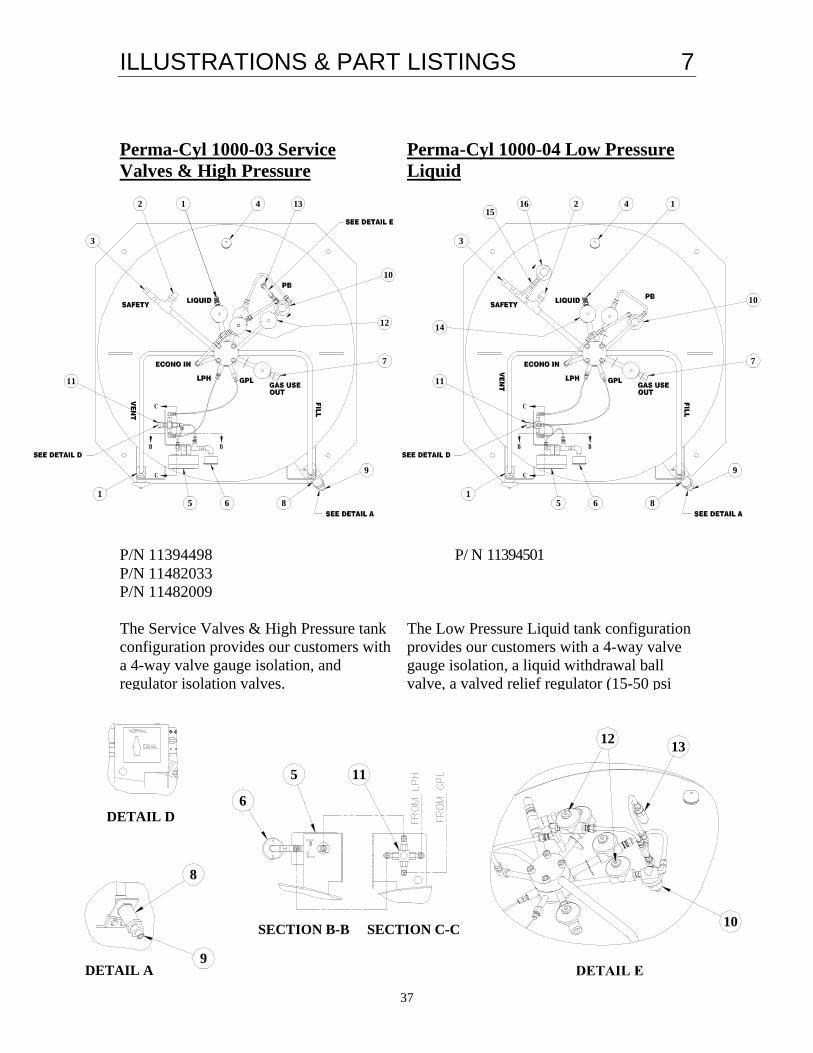
Perma-Cyl 1000-03 Service Perma-Cyl 1000-04 Low Pressure Valves & High Pressure Liquid
P/N 11394498 P/N 11394501 P/N 11482033 P/N 11482009 The Service Valves & High Pressure tank The Low Pressure Liquid tank configuration configuration provides our customers with provides our customers with a 4-way valve a 4-way valve gauge isolation, and gauge isolation, a liquid withdrawal ball regulator isolation valves. valve, a valved relief regulator (15-50 psi
range).
8
6
5
SECTION C-C
11
10
1312
DETAIL D
DETAIL A
SECTION B-B
9
2
3
1
11 11
1
7
10
8
9
5 61
4 14
7
10
1615
14
13
12
9
3
2
5 6 8

ILLUSTRATIONS & PARTS LISTING 7
38
DETAIL D
1112
13
1017DETAIL E
SECTION B-B SECTION C-C
6
5
DETAIL A9
8
Perma-Cyl 1000-05 CO2 Service P/N 11394519 P/N 11552548 The CO2 Service tank configuration provides our customers with a 4-way valve gauge isolation, regulator isolation valves, and a CO2 Package, including the patented Sure-fill System.
DETAIL F
18
8
9
5 61
11
7
10
412
3
18 12
1312

ILLUSTRATIONS & PART LISTINGS 7
39
7
8
9
5 61
42
3
1
11
12
10
1319
20
11
15 6 8
9
3
412 13
21
19
7
12
10
22
13
23
Perma-Cyl 1000 VHP-06 Perma-Cyl 1000-07 Lynx External PB ZX Super-Charged PB P/N 11717744 P/N 11725091
DETAIL A
8
9DETAIL D
SECTION B-B SECTION C-C
6
5 11
The Lynx PB option (06) adds performance benefits to the Perma-Cyl by decreasing the pressure recovery time after a fill and increasing the maximum withdrawal rate from the cylinder.
The ZX Supercharged PB (option 07) should be specified when the utmost in cylinder performance is required. This system will dramatically reduce pressure recovery time to around 15 minutes or less in most cases. When used with an external vaporizer, withdrawal rates of up to 7000 SCFH can be obtained.

ILLUSTRATIONS & PARTS LISTING 7
40
PERMA-CYL 1000 STANDARD: ITEM PART NO. DESCRIPTION
1a 1110072 Connection 1/2” ODT x 3/8” (45° Flare-Inert)
1b 1110112 Connection 5/8” ODT x
3/8” (45° Flare-OXY)
2a 11671281 Rupture Disk (375PSI)
2b 11526569 Rupture Disk (525PSI)
2c 11526622 Rupture Disk (700PSI)
3a 11488574 Relief Valve (250PSI)
3b 11488591 Relief Valve (350PSI)
3c 11385111 Relief Valve (500PSI)
4 3911217 Black Plastic Cap
ITEM PART NO. DESCRIPTION 5 11018142 Cyl-Tel Gauge
6a 2015179 Pressure Gauge (0-
400 PSI)
6b 2010064 Pressure Gauge (0-
600 PSI)
7a 4010022 Outlet 3/8" MPT
(INERT)
7b 4010012 Outlet 3/8" MPT
(OXY)
7c 4010562 Outlet 3/8" MPT
(CO2)
8 11051090 Check Valve 1/2” FPT x 1/2” FPT
9.1a 10873809 Quick Connect Fill
Fitting (ARG)

ILLUSTRATIONS & PART LISTINGS 7
41
ITEM PART NO. DESCRIPTION 9.1b 10873796 Quick Connect Fill
Fitting (OXY)
9.1c 10873817 Quick Connect Fill
Fitting (NIT)
9.1d 10582833 Quick Connect Fill
Fitting (CO2)
9.2a 1110122 Connection 1/2” ODT x
1/2” (45° Flare-Inert)
9.2b 1110912 Connection 5/8” ODT x
1/2” (45° Flare-OXY)
10a 11081336 Combination Regulator
1/4” NPT (125 PSI)
10b 11081328 Combination Regulator
1/4” NPT (300 PSI)
10c 11375625 Combination Regulator
1/4” NPT (450 PSI)
PERMA-CYL 1000 OPTIONS: ITEM PART NO. DESCRIPTION
10d 10645339 Combination Regulator 1/4” NPT (15-50PSI)
11 11026353 4-Way
Valve
12 1716702 1/4" Isolation
Valve
13 1812702 Line Relief Valve
(550PSI)
14 11539491 1/2" Ball Valve
15 1716162 1/4" Valve Iso.
SUC
16 11696795 Adjustable Relief
Regulator (35PSI)
7 1716702 1/4" Drain Valve
18 11567045 Sure Fill Assembly
(See Detail F)

ILLUSTRATIONS & PARTS LISTING 7
42
Perma-Cyl 1500 HP-02 Cyl-Tel Perma-Cyl 1500 HP-03 Service Gauge Service Valve Valves & High Pressure P/N 11560919 P/N 11551588 P/N 11552521 P/N 11552530 The Cyl-Tel Gauge Service Valve tank The Service Valves & High Pressure tank configuration provides our customers with configuration provides our customers with a 4-way valve gauge isolation. a 4-way valve gauge isolation, and regulator
isolation valves.
5
1
6
13
12
7
7
11
12
3
410
4
1
5
11 68 9 98
4
10
4
3
2 1
DETAIL B
5
VIEW A-A
OF VIEW A-APLUMBING VIEW
611
5
6
89

ILLUSTRATIONS & PART LISTINGS 7
43
DETAIL B
5
VIEW A-A
OF VIEW A-APLUMBING VIEW
611
5
6
89
13
12
77
15
16 14
12
18SEE DETAIL F
11
12
3
410
4
1
5
11 68 9 98
4
10
4
3
2 1
5
1
6
Perma-Cyl 1500 HP-04 Low Perma-Cyl 1500 HP-05 CO2 Service Pressure Liquid P/N1151570 P/N 11551561
P/N 11552513 The Low Pressure Liquid tank The CO2 Service tank configuration configuration provides our customers with provides our customers with a 4-way a 4-way valve gauge isolation, a liquid valve gauge isolation, regulator withdrawal ball valve, a valved relief isolation valves, and a CO2 Package, regulator (15-50 psi range). including the patented Sure-fill System.
DETAIL F
18

ILLUSTRATIONS & PARTS LISTING 7
44
PERMA-CYL 1500 HP STANDARD: ITEM PART NO. DESCRIPTION
1a 1110072 Connection 1/2” ODT x 3/8” (45° Flare-Inert)
1b 1110112 Connection 5/8” ODT x
3/8” (45° Flare-OXY)
2 11526569 Rupture Disk (525PSI)
3 11488591 Relief Valve (350PSI)
4 3911217 Black Plastic Cap
5 11018142 Cyl-Tel Gauge
6 2015179 Pressure Gauge (0-400
PSI)
7a 4010022 Outlet 3/8" MPT (INERT)
7b 4010012 Outlet 3/8" MPT (OXY)
ITEM PART NO. DESCRIPTION 7c 4010562 Outlet 3/8" MPT
(CO2)
8 11051090 Check Valve 1/2”
FPT x 1/2” FPT
9.1a 10873809 Quick Connect Fill
Fitting (ARG)
9.1b 10873796 Quick Connect Fill
Fitting (OXY)
9.1c 10873817 Quick Connect Fill
Fitting (NIT)
9.1d 10582833 Quick Connect Fill
Fitting (CO2)
9.2a 1110122 Connection 1/2” ODT
x 1/2” (45° Flare-Inert)
9.2b 1110912 Connection 5/8” ODT
x 1/2” (45° Flare-OXY)

ILLUSTRATIONS & PART LISTINGS 7
45
ITEM PART NO. DESCRIPTION 10a 11081328 Combination Regulator
1/4” NPT (300 PSI)
PERMA-CYL 1500 HP OPTIONS:
ITEM PART NO. DESCRIPTION 10b 10645339 Combination
Regulator 1/4” NPT (15-50PSI)
11 11627651 5-Way Valve
12 1716702 1/4" Isolation
Valve
13 1812702 Line Relief Valve
(550PSI)
14 11539491 1/2" Ball Valve
15 1716162 1/4" Valve Iso.
SUC
16
11696795 Adjustable Relief Regulator (35PSI)
17 116702 1/4" Drain Valve
18 11567045 Sure Fill Assembly
(See Detail F)

ILLUSTRATIONS & PARTS LISTING 7
46
8
7 7
4
2
3
4
1 14
10
9
14
11 6
13
12
12
3
4
10
4
1
5
11 68 9
1
5
Perma-Cyl 1500 VHP-02 Cyl-Tel Perma-Cyl 1500 VHP-03 Service Gauge Service Valve Valves & High Pressure P/N 11560935 P/N 11554244 The Cyl-Tel Gauge Service Valve tank The Service Valves & High Pressure configuration provides our customers with tank configuration provides our customers a 4-way valve gauge isolation. with a 4-way valve gauge isolation,
and regulator isolation valves.
DETAIL B
5
VIEW A-A
OF VIEW A-APLUMBING VIEW
611
5
6
89

ILLUSTRATIONS & PART LISTINGS 7
47
9811 6
5
1
4
3
2 1
13
10
4
12
7
19
20
5
1
7
4
4
3
2 1 10
19
22
13
21
23
8611
9
Perma-Cyl 1500 VHP-06 Perma-Cyl 1500 VHP-07 Lynx External PB ZX Super-Charged PB P/N 11717736 P/N 11722586
DETAIL B
5
VIEW A-A
OF VIEW A-APLUMBING VIEW
611
5
6
89
The ZX Supercharged PB (option 07) should be specified when the utmost in cylinder performance is required. This system will dramatically reduce pressure recovery time to around 15 minutes or less in most cases. When used with an external vaporizer, withdrawal rates of up to 7000 SCFH can be obtained.
The Lynx PB option (06) adds performance benefits to the Perma-Cyl by decreasing the pressure recovery time after a fill and increasing the maximum withdrawal rate from the cylinder.

ILLUSTRATIONS & PARTS LISTING 7
48
PERMA-CYL 1500 VHP STANDARD: ITEM PART NO. DESCRIPTION
1a 1110072 Connection 1/2” ODT x 3/8” (45° Flare-Inert)
1b 1110112 Connection 5/8” ODT x
3/8” (45° Flare-OXY)
2c 11526622 Rupture Disk (700PSI)
3c 11385111 Relief Valve (500PSI)
4 3910666 Blue Plastic Cap
5 11018142 Cyl-Tel Gauge
6b 2010064 Pressure Gauge (0-600
PSI)
7a 4010022 Outlet 3/8" MPT (INERT)
7b 4010012 Outlet 3/8" MPT (OXY)
ITEM PART NO. DESCRIPTION 7c 4010562 Outlet 3/8" MPT
(CO2)
8 11051090 Check Valve 1/2” FPT x 1/2” FPT
9.1a 10873809 Quick Connect Fill
Fitting (ARG)
9.1b 10873796 Quick Connect Fill
Fitting (OXY)
9.1c 10873817 Quick Connect Fill
Fitting (NIT)
9.1d 10582833 Quick Connect Fill
Fitting (CO2)
9.2a 1110122 Connection 1/2” ODT
x 1/2” (45° Flare-Inert)
9.2b 1110912 Connection 5/8” ODT
x 1/2” (45° Flare-OXY)
ILLUSTRATIONS & PART LISTINGS 7
49
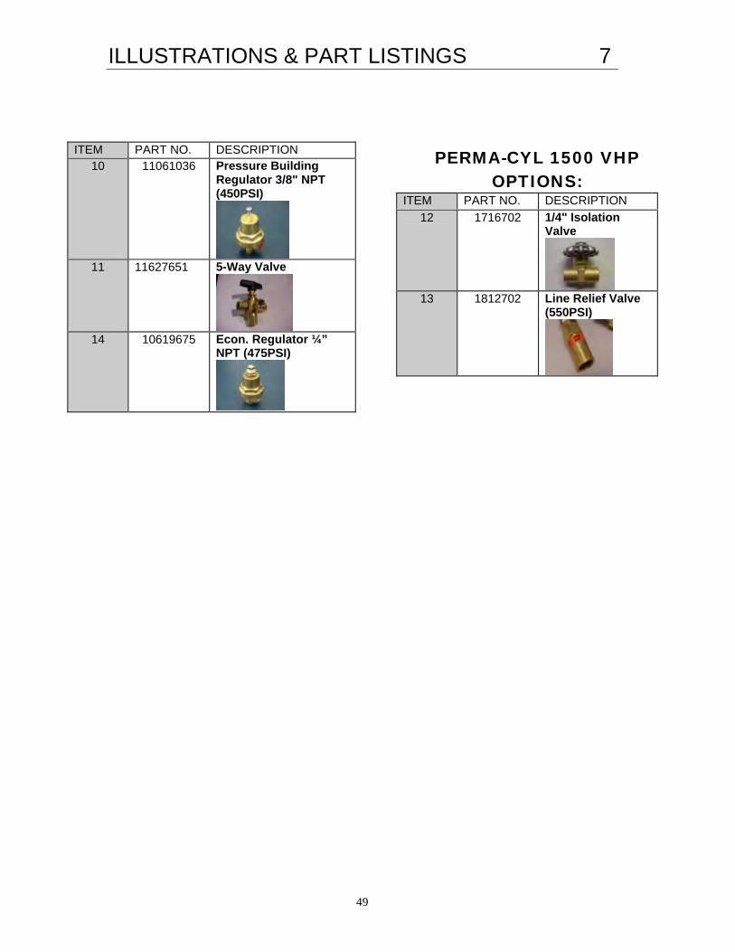
ITEM PART NO. DESCRIPTION 10 11061036 Pressure Building
Regulator 3/8" NPT (450PSI)
11 11627651 5-Way Valve
14 10619675 Econ. Regulator ¼”
NPT (475PSI)
PERMA-CYL 1500 VHP OPTIONS:
ITEM PART NO. DESCRIPTION 12 1716702 1/4" Isolation
Valve
13 1812702 Line Relief Valve
(550PSI)

WARRANTY 8
50
Chart Packaged Gas Products Warranty Policy Warranty only applies to original purchaser of Chart equipment and does not transfer to any other party. Materials, components and workmanship are warranted to be free of defects for 90 days from date of invoice. Vacuum integrity as measured by conformance to Chart NER (Normal Evaporation Rate) specifications is warranted as follows:
♦ Perma-Cyl, Mega-Cyl or Laser-Cyl liquid cylinders – 5 years from date of invoice. ♦ All Chart repaired liquid cylinders – 2 years from date of invoice.
Damage or abuse caused by purchaser voids Chart warranty obligations Freight damage incurred during shipment from Chart to purchaser must be reported immediately to Chart, and before placing equipment into service. In the event of a valid warranty claim, Chart reserves the right to repair, replace or refund the value of the equipment at its discretion. The warranty applies only to the purchased Chart equipment and in no case is Chart obligated to reimburse the purchaser for consequential damages resulting from the operation of Chart equipment.

SPECIFICATIONS 9
51
Description 230 Liter C 230 Liter C 230 Liter C 230 Liter 265 Liter 300 Liter 450 Liter 450 Liter 450 liter 450 Liter 700 Liter 1000 Liter 1000 Liter 1500 Liter 1500 Liter
MP, LCCM MP, LCCM HP, LCCM HP, LCCM MP MP HP MP HP VHP HP HP VHP HP VHP
Square Base
Round Base Square Base
Round Base Square Base
Plate Plate Plate Plate Plate Plate Plate Plate Pallet Pallet
w/Casters w/Casters w/Casters w/Casters w/Casters Base Base Base Base Base Base Base Base Base Base
Capacity (liters) Gross 240 240 240 240 276 330 450 450 450 450 688 1,056 1,056 1,550 1,550
Net 230 230 230 230 265 300 420 420 420 420 645 950 950 1,455 1,455
MAWP psig 235 235 350 350 235 250 350 250 350 500 350 350 500 350 500
bar 16.2 16.2 24.1 24.1 16.2 17.2 24.1 17.2 24.1 34.5 24.1 24.1 34.5 24.1 34.5
Design Spec DOT DOT DOT DOT DOT ASME DOT ASME ASME ASME ASME ASME ASME ASME ASME
Storage Capacity
Nitrogen SCF 5,024 5,024 4,734 4,734 5,769 7,380 8,875 10,332 10,332 10,332 15,860 23,370 23,370 35,550 35,550
Nm3 142 142 134 134 152 193 233.2 272 272 272 449 615 615 935 935
Oxygen SCF 6,244 6,244 5,930 5,930 7,186 9,100 11,111 12,760 12,760 12,760 19,600 28,861 28,861 43,900 43,900
Nm3 177 177 168 168 189 239 292 336 336 336 554 759 759 1,155 1,155
Argon SCF 6,073 6,073 5,763 5,763 6,982 8,850 10,812 12,478 12,478 12,478 19,160 28,225 28,225 42,950 42,950
Nm3 172 172 163 163 183 234 284.1 328 328 328 542 742 742 1,130 1,130
Thermal Performance
(NER%/Day) N 1.80% 1.80% 1.80% 1.80% 2.00% 1.20% 1.80% 1.80% 1.80% 1.80% 1.00% 1% 1% 1% 1%
O2 - Ar 1.12% 1.12% 1.12% 1.12% 1.40% 0.74% 1.12% 1.12% 1.12% 1.12% 0.62% 0.62% 0.62% 0.62% 0.62%
Gas Delivery Rate SCF/H 400 400 400 400 400 500 575 575 575 575 660 960 960 1,350 1,350
Nm3h 10.5 10.5 10.5 10.5 10.5 14.1 15.1 15.1 15.1 15.1 18.6 25.2 25.2 35.4 35.4
Dimensions
Diameter in 26 26 26 26 26 26 30 30 30 30 42 42 42 48 48
mm 660 660 660 660 660 660 762 762 762 762 1067 1,067 1,067 1,219 1,219
Tare Weight lbs 300 300 340 340 340 450 688 605 688 812 1165 1,750 2,080 2,692 3,200
Kg 136 136 154 154 154 204 312 274 312 368 529 794 945 1,221 1,451
Height in 54.8 52.9 54.8 52.9 57.8 68 68 68 68 68 66 81 81 91 91
mm 1,392 1,344 1,392 1,344 1,468 1,727 1,727 1,727 1,727 1,727 1,676 2,058 2,058 2,311 2,311

TROUBLESHOOTING 10
52
PROBLEM POSSIBLE CAUSE CORRECTIVE ACTION Perma-Cyl tank empty. 1. Switch to emergency gas supply.
2. Call gas supplier for delivery.
Gas Use Valve to final line regulator is closed or other valves downstream are closed.
1. Open valve or valves, as needed.
2. Insure there is no obstruction in the line or valve.
Pressure builder is not building sufficient pressure.
1. Open pressure building regulator control valve and allow pressure to build.
2. Adjust setting on regulator to a higher pressure.
3. If tank pressure fails to rise, see section on low tank pressure.
Final line pressure regulator set too low or malfunctioning.
1. Insure gas use valve is open and tank pressure is at least 25 psi higher than desired working pressure of final regulator.
2. Call service technician.
Inappropriate type of regulator (high-pressure or 2-stage or too small) installed as final line regulator and is not able to supply sufficient gas flow.
1. Insure gas use valve is open and tank pressure is at least 25 psi higher than desired working pressure of final regulator.
2. Inspect final line regulator or its specifications to determine if it has a suitable flow capacity for the required inlet and outlet pressures.
3. Call appropriate equipment supplier or service technician.
Gas supply line, hose, or network contains excessive pressure drop.
1. Check line for sufficient diameter.
2. Remove all unnecessary bends, elbows, reducers, and small diameter valves.
3. Check for leaks in the Gas Supply Line.
No gas to gas-use equipment.
OR
Insufficient pressure to gas-use equipment.
Unknown 1. Call service technician.
Normal condition during and following gas use, liquid use or filling.
1. NONE
2. User to check tank for frost / leaks before use.
Frost or ice on sides, bottom, top-center and/or plumbing of tank.
Tank is being used for continuous flow application and is not receiving sufficient ambient heat to melt the frost or ice. (Tank may have heavy ice build-up or continuous ice or frost.)
1. Move tank to a warmer location.
2. Add additional environmental heat and/or warm airflow to warm outer piping, components and sides of the tank.
3. Add a switchover system to allow tank to rest and warm up when not in use.

TROUBLESHOOTING 10
53
PROBLEM POSSIBLE CAUSE CORRECTIVE ACTION Leak in gas supply lines, gas-use equipment, or tank plumbing. (Frost is present on tank even after an extended period with no gas or liquid use.)
1. Evacuate & ventilate room.
2. If possible, locate and correct leak.
3. User to check tank for frost / leaks each morning before starting gas use.
4. Call appropriate equipment service technician.
Weak vacuum or failed vacuum. 1. Check if tank pressure is routinely high even during gas use and/or if tank has cold or ice spots even when not in operation as sign of vacuum problem.
2. Condensation or sweating is seen over the entire outer shell as a sign of vacuum problem.
3. Call gas service agent.
Frost or ice on sides, bottom, top-center and/or plumbing of tank.
(continued)
Unknown. 1. Call gas service agent.
PB shut-off valve is closed.
(If PB is not operating, no frost ring will appear at the bottom of the tank during gas use.)
1. Open pressure building regulator control valve and allow pressure to build.
2. Call service agent to repair, replace or adjust regulator.
Pressure builder setting is too low. (If PB is not operating, no frost ring will appear at the bottom of the tank during gas use.)
1. Adjust regulator to higher pressure and allow pressure to build.
2. Call service agent to repair, replace or adjust regulator.
Relief valve(s) is stuck open. 1. Evacuate & ventilate the room.
2. Check exhaust of relief valve to see if gas is flowing at a pressure below the pressure stamped on the valve.
3. Tap lightly on the side of the relief valve to attempt to dislodge any obstruction holding valve open. Repeat several times, if needed.
4. Call gas service technician to replace relief valve, if necessary.
Routinely low pressure in tank.
Large gas leak from tank plumbing or from gas use system.
1. Evacuate & ventilate the room.
2. If possible, locate and repair leak or call gas equipment service technician.

TROUBLESHOOTING 10
54
PROBLEM POSSIBLE CAUSE CORRECTIVE ACTION
Gas or liquid withdrawal rate exceeds the tank specifications.
1. Excess usage will cause tank pressure to decrease as PB is unable maintain pressure. Decrease withdrawal rate to within design specifications.
2. Increase pressure setting on PB regulator.
3. If withdrawing gas, consider: [a] withdrawing liquid and using external vaporizer, [b] installing larger tank, [c] installing additional tank(s), or [d] splitting application.
4. If withdrawing liquid, consider: [a] installing larger tank, [b] splitting application or [c] installing additional tank(s).
5. Call gas service agent.
Routinely low pressure in tank.
(continued)
Unknown 1. Switch to emergency gas cylinder.
2. Call gas service technician.
Ambient temperature surrounding the Perma-Cyl is too cold.
1. Move tank to warmer location.
2. Install freestanding ambient vaporizer on gas supply line in warmer location or install in-line gas heater.
Gas supply to gas-use equipment is too cold.
Gas withdrawal rate from Perma-Cyl exceeds the capacity of tank’s ambient vaporizer.
1. Reduce gas withdrawal rate to within specified parameters.
2. Install freestanding ambient vaporizer on gas supply line in warm location or install in-line heated vaporizer on gas supply circuit.
3. Install larger tank with greater withdrawal rate capacity.
Normal when little or no gas has been used for several days.
1. NONE – Routine use of gas will automatically reduce the tank pressure.
2. Gas usage must exceed NER of tank, if not, contact gas supplier for different tank model.
Routinely high tank pressure.
Economizer function on regulator is malfunctioning.
1. If tank is in a mixer application and the usage is low, consider drawing gas off the vent line, as the economizer will not work completely in non-consistent draws.
2. Call gas service technician to clean, repair, or replace regulator.

TROUBLESHOOTING 10
55
PROBLEM POSSIBLE CAUSE CORRECTIVE ACTION Tank is over-filled. 1. If tank is filled to or beyond proper fill level,
pressure builds very rapidly and relief valve may open.
2. Use gas or liquid as soon as possible to reduce tank contents.
3. Vent tank until no liquid is coming out the vent valve.
4. Follow liquid withdrawal procedures to transfer excess contents into a second tank and eliminate the over-fill situation. Avoid hazards of contact with cryogenic liquids, excess gas concentrations, or high pressure.
Pressure building function on regulator is set too high or regulator is malfunctioning.
1. Reduce pressure setting on by turning adjustment knob counter-clockwise to the desired pressure setting and continuing normal gas use until pressure drops
2. Close PB isolation valve and carefully observe pressure to insure tank pressure does not drop too low during use.
3. Call gas service technician to adjust PB regulator.
Weak or failed vacuum 1. Observe if condensation &/or frost are present even during periods of non-use as possible sign of vacuum problem.
2. Call gas service technician.
Routinely high tank pressure.
(continued)
Unknown. 1. Call gas service technician.
Normal for short periods of time from some regulators and relief valves.
1. Evacuate and ventilate room or area, if necessary.
2. If possible, observe leak. If leak is not large, does not last long, does not occur frequently and is in well-ventilated area, no action may be needed. If in doubt, call appropriate equipment service technician.
3. If above combined conditions do not exist, call equipment service technician and observe “Safety” precautions.
Hissing sounds or evidence of gas leaking near tank, gas lines, or gas-use equipment.
Large leaks, leaks from elsewhere in the system, sustained leaks, or frequent leaks (not normal).
1. Evacuate all personnel from affected areas. Ventilate room / area.
2. If possible, locate the leak and repair it or call gas service or gas-use equipment service technician.

TROUBLESHOOTING 10
56
PROBLEM POSSIBLE CAUSE CORRECTIVE ACTION
Unrecognized increase in actual gas use.
1. NONE for Perma-Cyl or gas supplier.
2. Gas user to determine reason for increase in gas use.
Leak in gas supply line or network or in gas-use equipment or tank plumbing, e.g. relief valve.
1. Evacuate & ventilate room, if necessary.
2. If possible, locate and repair leak or call gas-use equipment service agent.
3. User to check tank for frost / leaks before operations.
Tank pressure routinely too high and venting.
1. See troubleshooting section on routinely high tank pressure.
High flash or vaporization losses in liquid use application due to high pressure / temperature liquid in tank.
1. Vent tank to approximately 25 psi. Follow safety procedures.
2. In future only refill the Perma-Cyl with low-pressure cryogenic product.
High gas usage.
Error in gas delivery or supplier invoice.
1. Check gas usage history / pattern against supplier invoices.
2. Call gas supplier, if necessary.
Perma-Cyl is full. 1. NONE
Fill line is blocked or inoperative.
1. Check for obstructions in the fill line. Clear if necessary.
2. Gently tap on check valve to assure proper operation.
3. Call gas service technician.
ORCA Delivery Unit is not functioning properly.
1. Refer to ORCA Troubleshooting.
Perma-Cyl cannot be filled.
Transfer hose is obstructed, e.g. hose is bent excessively, crimped or plugged.
1. Clear obstruction, inspect hose for damage, and, if everything is satisfactory, continue the filling.
TROUBLESHOOTING 10
57
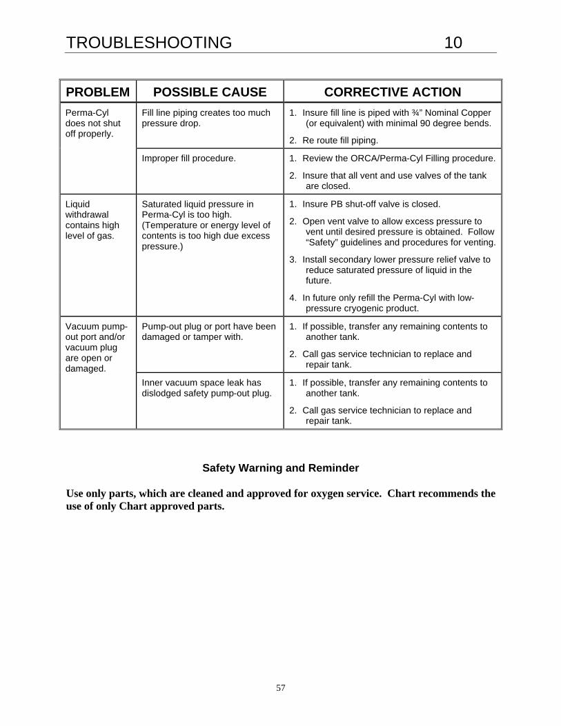
PROBLEM POSSIBLE CAUSE CORRECTIVE ACTION Fill line piping creates too much pressure drop.
1. Insure fill line is piped with ¾” Nominal Copper (or equivalent) with minimal 90 degree bends.
2. Re route fill piping.
Perma-Cyl does not shut off properly.
Improper fill procedure. 1. Review the ORCA/Perma-Cyl Filling procedure.
2. Insure that all vent and use valves of the tank are closed.
Liquid withdrawal contains high level of gas.
Saturated liquid pressure in Perma-Cyl is too high. (Temperature or energy level of contents is too high due excess pressure.)
1. Insure PB shut-off valve is closed.
2. Open vent valve to allow excess pressure to vent until desired pressure is obtained. Follow “Safety” guidelines and procedures for venting.
3. Install secondary lower pressure relief valve to reduce saturated pressure of liquid in the future.
4. In future only refill the Perma-Cyl with low-pressure cryogenic product.
Pump-out plug or port have been damaged or tamper with.
1. If possible, transfer any remaining contents to another tank.
2. Call gas service technician to replace and repair tank.
Vacuum pump-out port and/or vacuum plug are open or damaged.
Inner vacuum space leak has dislodged safety pump-out plug.
1. If possible, transfer any remaining contents to another tank.
2. Call gas service technician to replace and repair tank.
Safety Warning and Reminder Use only parts, which are cleaned and approved for oxygen service. Chart recommends the use of only Chart approved parts.

TROUBLESHOOTING 10
58
CHANGING SERVICE The Perma-Cyl Series cylinders are designed to hold any of the gas products specified. They can easily be modified to work as well with nitrogen as oxygen. The fittings and decals need to be changed and the inner vessel needs to be purged. WARNING: Once a cylinder is used in CO2 service, it can not be used for other gas products, especially oxygen or nitrous oxide. WARNING: Whenever converting a Nitrogen or Argon cylinder to Oxygen use, inspect the cylinder to assure cleanliness. Inner Vessel Purging Before any operation that involves pressure or handling of a cryogenic fluid, be sure all safety precautions are taken.
1. Open the vent to remove any pressure that has built in the inner vessel. 2. Open the pressure building valve to boil away any cryogenic liquid that remains in the
vessel. 3. Warm the inner vessel with warm nitrogen gas through the liquid valve. Check the gas
temperature as it escapes through the open vent valve. Continue until it is warm. 4. Close the liquid valve, gas use valve and pressure building valve. 5. Attach a vacuum pump to the vent valve and evacuate the inner vessel to 26 inches of
mercury. 6. Break the vacuum to 5 psig with high purity gas as required by the service of the
container. 7. Repeat steps 5 and 6 twice. 8. Close all valves and remove the vacuum and gas purge lines. The container is now
ready for filling. ASSOCIATED MANUALS The following manuals are available for reference on related topics. All manuals are available on the MicroBulk Toolkit CD. Description Part Number Perma-Cyl Installation 11630833 Cyl-Tel Operation 11076422 Cyl-Tel 2 Operation 11761841 OnSite Telemetry 11771370 All manuals are available free of charge by contacting Chart Industries Customer Service at (800) 400-4683.

59
P/N 10961999 Rev C 10/03
CHART Inc. Distribution & Storage Group 407 Seventh Street Northwest New Prague, MN 56071 USA Phone: 800-400-4683 Fax: 952-758-8215