upgrade your hydraulic control - hydro.com.pl · this catalogue contains the information needed for...
TRANSCRIPT

UPGRADE YOUR HYDRAULIC CONTROL
BM70BM100BF701
BM70 / BM100 / BF701 w w w. b l b h y d r a u l i c . c o m2
PRESENTATION
This catalogue contains the information needed for the selection and proper use of the hydraulic directional control valve BM70, BM100 and BF701 Series.The design, manufacturing process and controls meet the relevant EU standards and directives on safety and quality. BM70, BM100 and BF701 directional control valve are produced by BLB Srl.
WARNINGS
Before using BM70, BM100 and BF701 directional control valves carefully read this catalogue in all its parts. The applications of these products must comply with the information contained in it. Contact our BLB technical department in all cases in which the correspondence of the product to the application requirements is uncertain.
The proper operation of BM70, BM100 and BF701, is strictly subjected to the compliance with the directions, instructions, and speci�cations stated in this catalogue. Therefore, operations and uses that require actions other than those herein described and/or approved in advance by BLB srl., may give rise to defects or failures that exempt BLB from all liabilities. To ensure the speci�cations given in the catalogue, make sure that the maximum parameters are not exceeded during operation.
BLB is not liable for any damage that may be caused to persons or property resulting from misuse of the product. Therefore, consult with the utmost attention the chapter instructions.
The catalogue shows the most common con�gurations. For more detailed information or special requests herein not provided, please contact BLB Srl Sales Department.
Speci�cations, drawings and descriptions contained in this catalogue refer to the standard product at the date of publication of this catalogue. Blb, in a perspective of continuous product improvement, reserves the right to make changes at any time and without the obligation of any prior noti�cation.
First Edition January 2016 C-BM70, BM100 and BF701
BLB S.r.l. Via Natta 1, 36040 Brendola (VI) Italy
T. +39 0444 401141 W. www.blbhydralic.com

BM70 / BM100 / BF701w w w. b l b h y d r a u l i c . c o m 3
APPLICATIONS
Waste compactor Log splitter Compactor
Boat Winch
Fork Lift
Hedge MowersSewage Cleaning
Sewage Cleaning
BM100
BF701
BM70

BM70 / BM100 / BF7014 w w w. b l b h y d r a u l i c . c o m

BM70 / BM100 / BF701 5w w w. b l b h y d r a u l i c . c o m
GENERAL INFORMATION BM70 / BM100
DESIGNATION BM70 / BM100
TECHNICAL SPECIFICATIONS BM70
TECHNICAL SPECIFICATIONS BM100
BM70 AUTOSPEED
BM70/100 WITH ROTARY CONTROL
GENERAL INFORMATION BF701
DESIGNATION BF701
TECHNICAL SPECIFICATIONS BF701
SPARE PARTS:
RELIEF VALVES AND ACCESSORIES
ACTUATORS
SPOOLS
SPOOL CONTROLS
PLUGS
INSTRUCTIONS
6
7
8
9
10
11
12
13
14
15
15
18
22
26
32
34
SUMMARY

BM70 / BM100 w w w. b l b h y d r a u l i c . c o m6
CO
P
RV P
B A
By
T
10
BA
2
B A
PT
10
BA
2P
P2
V L
T2
T
B A
PT
10
BA
2
T
CC P
TP
P2
T T
GENERAL INFORMATION
This booklet is meant to be a technical deepening on directional control valves of the BM70 and BM100 series. These monoblock valves are characterized by a single body having following features:
• Sound construction.• Compact size.• Reduced weight.
The absence of tie rods and intermediate seals allow monoblock valves to provide:
• Improved dependability.• Sturdy valves body for fewer leak points.• Lower maintenance.
WITHOUT RELIEF VALVE STANDARD CLOSED CENTER HIGH PRESSURE CARRY OVER (POWER BEYOND)
BM70 / BM100
BM70 BM100

BM70 / BM100w w w. b l b h y d r a u l i c . c o m 7
DESIGNATION
BF701 | 3 G U | MO D 2 | MO A 1 | MO A 1 |
Valve
N. o
f Lev
ers
Thre
ads
Relie
f Val
ve
Spoo
l
Spoo
l Con
trol
Actu
ator
Spoo
l
Spoo
l Con
trol
Spoo
l
Spoo
l Con
trol
BA
INLET
U SPOOL CONTROL
B 2OUTLETSPOOL CONTROL
A 1SPOOL CONTROL
L 12 0C
PP2
UT
10
2
PT A
10
2
PT
PT
10
223
BA
BA
B AA B A T
T2
BM70 / BM100
Actu
ator
Actu
ator

BM70 w w w. b l b h y d r a u l i c . c o m8
TECHNICAL SPECIFICATIONS BM70
70 l/min80 l/min60 l/min250 bar320 bar160 bar80 bar
18.5 GPM21,5 GPM16 GPM3600 PSI4700 PSI2300 PSI1100 PSI
A - B → T 4 ÷ 8 cc/min
G (BSP)F (UNF)
1/2" 7/8" -14
100 bar40 °C32 mm²/s
1/2" 7/8" -14
1/2" 7/8" -14
A - B P T
BM70/1BM70/2BM70/3BM70/4BM70/5BM70/6
115155195235275315
4.526.17.679.2510.812.4
65105145185225265
2.554.135.77.288.8510.43
4.57.49.911.413.616
L Ilbkg
9.116.521.125.229.235.4
(mm) (inch) (mm) (inch)
3/4" 1.1/16" -12
3/4" 1.1/16" -12
P2 T2NOMINAL FLOW MAX FLOWMAX FLOW - Electrical controlNOMINAL PRESSUREMAX PRESSURE ON PORTSMAX PRESSURE ON PORTS - Electrical controlMAX PRESSURE ON TANK-LINE
TECHNICAL CHARACTERISTICS
INTERNAL OIL LEAKAGE
STANDARD THREADS
PRESSUREOIL TEMPERATUREOIL VISCOSITY
TESTING CONDITIONS
STANDARD THREADS
NUMBER OF SECTIONS
PRESSURE DROP
65
25
L
B
A A A A
B B B
T
T2P
P2
I30
119
12
35
71
45
8313
152
226
60 40 40 40 35
M10Ø10,5
3
02
1
A/B → TP → A/BP → T
0
1
2
3
4
5
6
7
8
9
10
0 10 20 30 40 50 60 70 80
PRES
SURE
(bar
)
FLOW (l/min.)
/6
/5
/4
/3
/2
/1
P T
1 2 3 4 5 6
0
5
10
15
20
25
0 10 20 30 40 50 60 70 80
PRES
SURE
(bar
)
FLOW (l/min)
/6
P
B
A
/5
/4
/3
/2
/1
1 2 3 4 5 6
0
1
2
3
4
5
6
7
8
9
10
0 10 20 30 40 50 60 70 80
PRES
SURE
(bar
)
FLOW(l/min)
/6
/5
/4
/3
/2
/1
B
A
T
6 5 4 3 2 1
BM100w w w. b l b h y d r a u l i c . c o m 9
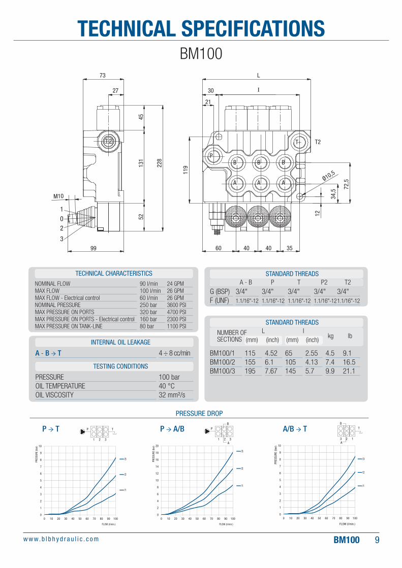
BM100TECHNICAL SPECIFICATIONS
A - B → T 4 ÷ 8 cc/min
G (BSP)F (UNF)
3/4" 1.1/16"-12
100 bar40 °C32 mm²/s
3/4"1.1/16"-12
3/4"1.1/16"-12
3/4"1.1/16"-12
3/4"1.1/16"-12
A - B P T P2 T2
BM100/1BM100/2BM100/3
115155195
4.526.17.67
65105145
2.554.135.7
4.57.49.9
L Ilbkg
9.116.521.1
(mm) (inch) (mm) (inch)
90 l/min100 l/min60 l/min250 bar320 bar160 bar80 bar
24 GPM26 GPM26 GPM3600 PSI4700 PSI2300 PSI1100 PSI
NOMINAL FLOW MAX FLOWMAX FLOW - Electrical controlNOMINAL PRESSUREMAX PRESSURE ON PORTSMAX PRESSURE ON PORTS - Electrical controlMAX PRESSURE ON TANK-LINE
TECHNICAL CHARACTERISTICS
PRESSURE DROP
INTERNAL OIL LEAKAGE
STANDARD THREADS
PRESSUREOIL TEMPERATUREOIL VISCOSITY
TESTING CONDITIONS
STANDARD THREADS
NUMBER OF SECTIONS
73 L
I
99
M10
27 30
60 40 40 35
21
T2T 2 T
PB B B
A A A11
9
34,5
Ø10,5
72,5
12
4513
1
228
52
3
02
1
A/B → TP → A/BP → T
0
1
2
3
4
5
6
7
8
9
10
0 10 20 30 40 50 60 70 80 90 100
PRES
SURE
(bar
)
FLOW (l/min.)
/3
/2
/1
1 2 3
P T
0
2
4
6
8
10
12
14
16
18
20
0 10 20 30 40 50 60 70 80 90 100
PRES
SURE
(bar
)
FLOW (l/min:)
/3
/2
/1
1 2 3
PB
A
0
1
2
3
4
5
6
7
8
9
10
0 10 20 30 40 50 60 70 80 90 100
PRES
SURE
(bar
)
FLOW (l/min.)
/3
/2
/1
3 2 1
B
A
T

BM70 w w w. b l b h y d r a u l i c . c o m10
BM70 AUTOSPEED
Special valve dedicated to log-splitter applications, both horizontal and vertical.Main features are the fast approach to the log (with max �ow and pressure <70 bar) and the following passage to the log-cutting mode (with low �ow and max pressure).
Available with or without the kickout feature (automatic return from back position to center).
Max pump �ow: 55/60 l/min – 14.4/15.8 GPM
1BACK
T2
P2
K
10
2
BA
PT
INLET
K SPOOL CONTROL
S 6
OUTLET
OC
P
T DR
0CENTER
2WORK
AB
T2
P2
K
10
2
BA
PT
INLET
K SPOOL CONTROL
S 6
OUTLET
OC
P
T DR
AB
T2
P2
K
10
2
BA
PT
INLET
K SPOOL CONTROL
S 6
OUTLET
OC
P
T DR
AB
Log splitter
72 115
107
231
P2P
A
B
T
65

BM70 / BM100w w w. b l b h y d r a u l i c . c o m 11
ROTARY CONTROLBM70 / BM100
70°
70°
Mainly used in marine equipments to control the speed of the �shing winches motors, rotary control is available on BM70 and BM100 series.
The valve is operated turning the lever into a range of 70°+70°. The spool is detended (frictioned) in every position inside the overmentioned range.Valves are protected against marine corrosion with the Black Dacromet treatment and many components are realized in stainless steel.
Boat winch
INLET
SPOOL CONTROL OUTLETUD 1R 0C
PP2
UT
T
T
10
2
PT
BA
B A

BF701 w w w. b l b h y d r a u l i c . c o m12
GENERAL INFORMATIONBF701
BF monoblock valves series derives from BM series and differs from it for having integrated in the inlet a pressure compensated �ow control either 3/ways priority (RFP) or 2/ways (RFS).
With RFP �ow control, the exceeding �ow is recuperated into the system and allows the simultaneous use of two spools, the �srt fed by the priority �ow (PF) and the second fed by the exceeding �ow (EF).
With RFS �ow control, the exceeding �ow goes to tank.
Very important characteristic is that the �ow control only works when a priority element is actuated; if no priority element is operated, oil goes to tank eliminating loss of �ow and unnecessary heating.
In RFP version, non-priority sections get the whole valve �ow when they are individually operated or just the exceeding �ow when a priority section is oerated. One or more priority elements are available.
WITHOUT RELIEF VALVE STANDARD CLOSED CENTERHIGH PRESSURE CARRY OVER
(POWER BEYOND)
PP2
T
RVP
CO
TT
CCP
T
U
P2P
A
2
B
01
T P
AB
A
2
B
01
T P
AB
T2
TB A
PT
10
B
2
A

BF701w w w. b l b h y d r a u l i c . c o m 13
DESIGNATIONBF701
BF701 | 3 G U | MO D 2 | MO A 1 | MO A 1 |
BF701
/1 /2 /3 /4 /5Priority Flow Element
Exceeding Flow Element
SPOOL CONTROL
D 2OUTLETSPOOL CONTROL
A 1SPOOL CONTROL
A 1 0C
PP2
T
U
10
2
PT A
1
02
PT
PT
10
2
3
BA
BA
B
1
B AA B A T
T2
B
Valve
N. o
f Lev
ers
Thre
ads
Relie
f Val
ve
Spoo
l
Actu
ator
Spoo
l Con
trol
Actu
ator
Spoo
l
Spoo
l Con
trol
Actu
ator
Spoo
l
Spoo
l Con
trol

BF701 w w w. b l b h y d r a u l i c . c o m14
0
1
2
3
4
5
6
7
8
9
10
0 10 20 30 40 50 60 70 80
PRES
SURE
(bar
)
FLOW (l/min.)
/5/4/3/2/1
P T
1 2 3 4 5
0
2
4
6
8
10
12
14
16
0 10 20 30 40 50 60 70 80
PRES
SURE
(bar
)
FLOW (l/min.)
/5
/4
/3
/2
/1
BT
A5 4 3 2 1
0
5
10
15
20
25
30
0 10 20 30 40 50 60 70 80
PRES
SURE
(bar
)
FLOW (l/min.)
/5
/4
/3
/2
/1
P
B
A1 2 3 4 5
70 l/min80 l/min250 bar320 bar80 bar
18.5 GPM21,5 GPM3600 PSI4700 PSI1100 PSI
TECHNICAL SPECIFICATIONS
A - B → T 4 ÷ 8 cc/min
G (BSP)F (UNF)
1/2"7/8"-14
100 bar40 °C32 mm²/s
1/2"7/8"-14
1/2"7/8"-14
3/4"1.1/16"-12
3/4"1.1/16"-12
A - B P T P2 T2
BF701/1BF701/2BF701/3BF701/4BF701/5
155195235275315
6.17.679.2510.812.4
105145185225265
4.135.77.288.8510.43
6.6911.213.515.7
L Ilbkg
14.819.124.125.135
(mm) (inch) (mm) (inch)
BF701
NOMINAL FLOW MAX FLOWNOMINAL PRESSUREMAX PRESSURE ON PORTSMAX PRESSURE ON TANK-LINE
TECHNICAL CHARACTERISTICS
INTERNAL OIL LEAKAGE
STANDARD THREADS
PRESSUREOIL TEMPERATUREOIL VISCOSITY
TESTING CONDITIONS
STANDARD THREADS
NUMBER OF SECTIONS
65 L
25
98
30
20
60 40 40 40 35
83
12
119
45
36
131
M10
M10
52PP
AAA AAA AAA
BBB BBB BBBP2
T2TT
T2T2
3
0
2
1
I
Ø11
PRESSURE DROP
P → T A/B → TP → A/B

BM70 / BM100 / BF701 15w w w. b l b h y d r a u l i c . c o m
0 10 20 30 40 50 60 70 80 90 1000
50
100
150
200
250
300
350
400
PR
ESS
UR
E (b
ar)
FLOW (l/min.)
Oil temperature= 50°CViscosity = 21 CSt
setting 150 bar
Setting 300 bar
0 10 20 30 40 50 60 70 80 90 1000
50
100
150
200
250
300
350
400
PR
ESS
UR
E (b
ar)
FLOW (l/min.)
Oil temperature= 50°CViscosity = 21 CSt
setting 90 bar
Setting 250 bar
0
20
40
60
80
100
120
140
160
180
0 10 20 30 40 50 60 70 80 90 100
PR
ESS
UR
E (b
ar)
FLOW (l/min.)
Oil temperature= 50°CViscosity = 21 CSt
setting 50 bar
Setting 90 bar
SPARE PARTSRelief valves and accessories
- Standard setting is based on a pre-set �ow of 14 l/min.
X
U
K
XB
UB
KB
X: Pressure Range 30 ÷ 90 bar - STANDARD SETTING 70 bar
U: Pressure Range 80 ÷ 230 bar - STANDARD SETTING 140 bar
K: Pressure Range 150 ÷ 300 bar - STANDARD SETTING 180 bar
B: Prearranged for lock kit
VALVE X - Code 803018
VALVE XB - Code 803110VALVE K - Code 803013
VALVE KB - Code 803105
VALVE U - Code 803064
VALVE UB - Code 803076
RELIEF VALVE VL80
PRESSURE RANGE VL80
SPRING X SPRING U SPRING K
P
T
T2P2
A
B B B B
A A A

BM70 / BM100 / BF70116 w w w. b l b h y d r a u l i c . c o m
Applied to VL_B prevents users alteration of the prearranged relief valve setting.
PB - RELIEF VALVE LOCK KIT Code 560945
Replaces VL in closed center systems (i.e. John Deere tractors), in circuits where an in-line relief valve is provided or in case of two valves connected downstream by means of a carry over (power beyond) plug.
RVP - RELIEF VALVE PLUG
Every BLB valve is provided with a load check valve VNR; it prevents the cylinder fall when a spool is actuated and the back�ow from ports to inlet.
VNR - LOAD CHECK VALVE KIT (BM70 / BM100) Code 560274
Code 832012
SPARE PARTS

BM70 / BM100 / BF701 17w w w. b l b h y d r a u l i c . c o m
Every BLB valve is provided with a load check valve VNR; it prevents the cylinder fall when a spool is actuated and the back�ow from ports to inlet.
VNR - LOAD CHECK VALVE KIT - Horizontal (BF701) Code 560239
Every BLB valve is provided with a load check valve VNR; it prevents the cylinder fall when a spool is actuated and the back�ow from ports to inlet.
VNR - LOAD CHECK VALVE KIT - Vertical (BF701) Code 560241
Horizontal Vertical
SPARE PARTS

BM70 / BM100 / BF70118 w w w. b l b h y d r a u l i c . c o m
Actuators
Standard manual control with lever. Possibility to assembly the lever in vertical or horizontal position.Possibility to assembly the entire manual control in position A(90°) or B(180°).
MO - MANUAL LEVER CONTROL Code 801014
Manual control as 801014 but the lever is not included.
MW - MANUAL WOTHOUT LEVER Code 801116
C
D
A
B
20
1
20
1
20
1
The actuator orientation is “A” if not differently requested
210
AB
Manual control as 801014 with the addition of a cam.
MC - MANUAL WITH CAM Code 801010
SPARE PARTS

BM70 / BM100 / BF701 19w w w. b l b h y d r a u l i c . c o m
Cam actuator.
DO - CAM Code 801044
Hydraulic actuator for remote control.
HO - HYDRAULIC Code 801246 - SingleCode 561068 - Double
The lever can be actuated only after the mechanical security system is released. It can be combined with other actuators in other sections.
MX - SAFETY LEVER Code 801262
It allows the spool positioning in all the positions within the minimum and the maximum stroke. The lever has to be rotated around the spool axis. See page 31 for the spool control features (8DN).
MR - MANUAL ROTARY LEVER (BM70 / BM100 ROTATIVO) Code 801301
Operates two spools with one lever handle. Two spools can be operated indipendently or simultaneously, depending on the movement of the handle.Joystick requires to be assembled with spools AS, BS, DS.
JS1 - MEHCANICAL JOYSTICK Code JS1 - 801291
Code JS2 - 801292JS2 - MEHCANICAL JOYSTICK
Operates two spools with one lever handle. Two spools can be operated indipendently or simultaneously, depending on the movement of the handle.Joystick requires to be assembled with spools AS, BS, DS.
SPARE PARTS
1 20
B2
A2
A1B1
A1 B1 A2 B2
P
T
B1
A1
A2B2
A1 B1 A2 B2
P
T

BM70 / BM100 / BF70120 w w w. b l b h y d r a u l i c . c o m
Modular single lever for cable remote control to be assembled with push-pull cables.
FO - MODULAR SINGLE LEVER Code 801329
Modular single lever with antireverse lock. Allows the operation of the lever only when the lock system is released.
FA - MODULAR SINGLE LEVER WITH ANTIREVERSE LOCK Code 801332 (R) Code 801336 (L)
Operates 2 spools with one handle, through �exible cables. Spools can be operated indipendently or simultaneously, depending on the movement of the handle.
FJ1 - MECHANICAL JOYSTICK FOR FLEXIBLE CABLES Code FJ1 - 801297
Cable adapter for cable control. It allows the assembly of cable on the valve on the lever side.
FL - CABLE ADAPTER Code 801331
023038023087023088023089023090023091023092023093
CA... - CABLE Code CA 0.5 CA 1.0CA 1.5CA 2.0CA 2.5CA 3.0CA 3.5CA 4.0
L [mt]
Operates 2 spools with one handle, through �exible cables. Spools can be operated indipendently or simultaneously, depending on the movement of the handle.
FJ2 - MECHANICAL JOYSTICK FOR FLEXIBLE CABLES Code FJ2 - 801298
Right Left
SPARE PARTS
B2
A2
A1 B1
PT
A1 B1 A2 B2
A1
A2B2
B1
PT
A1 B1 A2 B2

BM70 / BM100 / BF701 21w w w. b l b h y d r a u l i c . c o m
The electric remote control is used when the directional control valve has to be placed away from the operator. Electric source required.
EO 12V - ELECTRIC OPERATOR Code 801519
The electric remote control is used when the directional control valve has to be placed away from the operator. Electric source required.
EO 24V - ELECTRIC OPERATOR Code 801520
SPARE PARTS
1 20
1 20

BM70 / BM100 / BF70122 w w w. b l b h y d r a u l i c . c o m
Spools
Provides control of double-acting cylinders or bi-directional hydraulic motors. In position 0 work ports are blocked.
SPOOL A | 4-WAY / 3-POSITION SPOOL Code 560381
Same features as spool A but with threaded spool end. Required to assembly joysticks (JS), for valves with right inlet or for special applications.
SPO0L AS | 4-WAY / 3-POSITION SPOOL Code 560852
Same features as spool A but without meetering. Required for special applications (i.e. woodsplitter).
SPO0L SP | 4-WAY / 3-POSITION SPOOL Code 560337
SPARE PARTS
1B A0 2
By P T
1B A0 2
By P T
20
1
20
1
20
1 210
AB
A/B = PortsBy = BypassP = PressureT = Tank
1B A0 2
By P T

BM70 / BM100 / BF701 23w w w. b l b h y d r a u l i c . c o m
Provides control of single-acting cylinders or start and stop of uni-directional hydraulic motors. In position 0 work port A is blocked. B port is plugged.
SPO0L B | 3-WAY / 3-POSITION SPOOL Code 560378
Same features as spool B but with threaded spool end. Required to assembly joysticks (JS), for valves with right inlet or for special applications.
SPO0L BS | 3-WAY / 3-POSITION SPOOL Code 560126
Provides control of single-acting cylinders or start and stop of uni-directional hydraulic motors. In position 0 work port B is blocked. A port is plugged.
SPO0L C | 3-WAY / 3-POSITION SPOOL
Provides control of double acting cylinders or bi-directional hydraulic motors. Allows a cylinder to �oat or a motor to wheel free when the spool is in position 0. Work ports are open to the tank when the spool is in position 0.
SPO0L D | 4-WAY / 3-POSITION SPOOL, OPEN CENTER (MOTOR SPOOL) Code 560379
SPO0L DS | 4-WAY / 3-POSITION SPOOL, OPEN CENTER (MOTOR SPOOL) Code 560128
Code 560138
Same features as spool D but with threaded spool end. Required to assembly joysticks (JS), for valves with right inlet or for special applications.
SPARE PARTS
1B A0 2
By P T
1B A0 2
By P T
1B A0 2
By P T
1B A0 2
By P T
1B A0 2
By P T
SPO0L L | 4-WAY / 4-POSITION, FLOATING SPOOL Code 560142
Same features as spool A with the addition of a fourth �oating position. The �oating position allows a cylinder to �oat or a motor to wheel free when the spool is in position 3. To be combined only with spool controls 12, 13. Special machining on the body is required.
1B A0 2 3
By P T

BM70 / BM100 / BF70124 w w w. b l b h y d r a u l i c . c o m
SPO0L Z | 4-WAY / 4-POSITION, REGENERATIVE SPOOL Code 560146
Double-acting spool regenerative in position 3, for valves with right inlet. The regenerative circuit allows the cylinder to increase its speed, in one way only, adding to the pump �ow the oil returning from the rod chamber of the cylinder. To be combined only with spool controls 42 or 43. Special machining on the body is required.
SPO0L WS | 4-WAY / 4-POSITION, REGENERATIVE SPOOL Code 560807
Regenerative spool in position 2. The regenerative circuit allows the cylinder double-acting to increase its speed, in one way only, adding to the pump �ow the oil returning from the rod chamber of the cylinder. Special machining on the body is required.
SPO0L R | 4-WAY / 3-POSITION, REGENERATIVE SPOOL Code 560474
Spool with regenerative circuit in position 3. The regenerative circuit allows the cylinder to increase its speed, in one way only, adding to the pump �ow the oil returning from the rod chamber of the cylinder. To be combined only with spool controls 14, 26, 42 or 43. Special machining on the body is required.
Provides control of bi-directional motors. The neutral position is in position 1.Special machining on the body required.
SPO0L Y | 4-WAY / 3-POSITION SPOOL Code 560778
Same features as spool A to be used in a closed center system (i.e. John Deere).
SPO0L M | 4-WAY / 3-POSITION SPOOL Code 560143
SPARE PARTS
01B A
2 3
By P T
13B A0 2
By P T
1B A0 2
By P T
1B A0 2
By P T
1B A0 2
By P T
Regenerative spool for BM70 Autospeed.In position 2, with low pressure (up to 70 bar), it increases the cylinder opening speed; above 70 bar, it becomes a standard double acting circuit.
SPO0L S | 4-WAY / 3-POSITION, REGENERATIVE SPOOL (BM70 AUTOSPEED) Code 560874
1B A0 2
By P T

BM70 / BM100 / BF701 25w w w. b l b h y d r a u l i c . c o m
Same features as spool A. In position 0 work port B is connected to the tank.
SPO0L E | 4-WAY / 3-POSITION SPOOL
Same features as spool A. In position 0 work port A is connected to the tank.
SPO0L F | 4-WAY / 3 -POSITION SPOOL Code 560141
Code 560140
SPARE PARTS
1B A0 2
By P T
1B A0 2
By P T

BM70 / BM100 / BF70126 w w w. b l b h y d r a u l i c . c o m
Spool controls
SPOOL CONTROL 1 | 3 POSITIONS Code 802127
Same features as spool control 1 with 3 positions 0-1-2: when the lever is pushed in position 1 the spool is detended.
Code 802016
Same features as spool control 1 with 3 positions 0-1-2: when the lever is pulled in position 2 the spool is detended.
SPOOL CONTROL 3 | 3 POSITIONS Code 802017
Allows the spool to move in position 1 and 2 by pushing and pulling the lever: spool goes back to position 0 when the handle is released (Spring return).
20
1
20
1
20
1
SPOOL CONTROL 2 | 3 POSITIONS
210
AB
POSITION 0: P → TPOSITION 1: P → BPOSITION 2: P → A
BOLD = Starting positionORANGE = Detent position
SPARE PARTS
1 0 2
1 0 2
1 0 21 0 2
1 0 21

BM70 / BM100 / BF701 27w w w. b l b h y d r a u l i c . c o m
Allows the spool to move only in position 0 and 2: spool goes back to position 0 when the handle is released (Spring return).
SPOOL CONTROL 4 | 2 POSITIONS Code 802018
Allows the spool to move only in position 0 and 1: spool goes back to position 0 when the handle is released (Spring return).
SPOOL CONTROL 5 | 2 POSITIONS Code 802019
In neutral position, spool is in position 1.Pulling the lever spool passes through position 0 and gets to position 2.
SPOOL CONTROL 6 | 2 POSITIONS
In neutral position, spool is in position 2.Pushing the lever spool passes through position 0 and gets to position 1
SPOOL CONTROL 7 | 2 POSITIONS Code 802021
Code 802020
Spool is detented in all positions: 0, 1 and 2.
SPOOL CONTROL 8 | 3 POSITIONS Code 802022
Spool is detented in all positions: 0 and 1.
SPOOL CONTROL 9 | 2 POSITIONS Code 802023
SPARE PARTS
0 2
01
1 2
1 0
1 2
1 0 21 0 2

BM70 / BM100 / BF70128 w w w. b l b h y d r a u l i c . c o m
SPOOL CONTROL 11 | 2 POSITIONS Code 802025
The spool returns to 0 from positions 1 and 2 when the handle is released. Position 3 is detented. To be combined only with spool L.
SPOOL CONTROL 12 | 4 POSITIONS Code 802026
The spool is detented in all positions. To be combined only with spool L.
SPOOL CONTROL 13 | 4 POSITIONS Code 802027
The spool returns to position 0 when the handle is released. To be combined only with spools Z or WS.
SPOOL CONTROL 14 | 4 POSITIONS Code 802047
Spool is detented in all positions: 1 and 2. Position 0 is absent.
The spool returns to position 1 when the handle is released. The spool is detented in position 2.To be combined only with spools Z or WS.
SPOOL CONTROL 26 | 4 POSITIONS Code 802309
Spool is detented in all positions: 0 and 2.
SPOOL CONTROL 10 | 2 POSITIONS Code 802024
SPARE PARTS
1 2
1 0 32
Spool Z
Spool Z
Spool WS
Spool WS
31 20
3 1 20
31 20
3 1 20
0 20 2
1 0 32 3
BM70 / BM100 / BF701 29w w w. b l b h y d r a u l i c . c o m
The spool is detented in position 2 and returns to position 1 from position 0 when the handle is released.
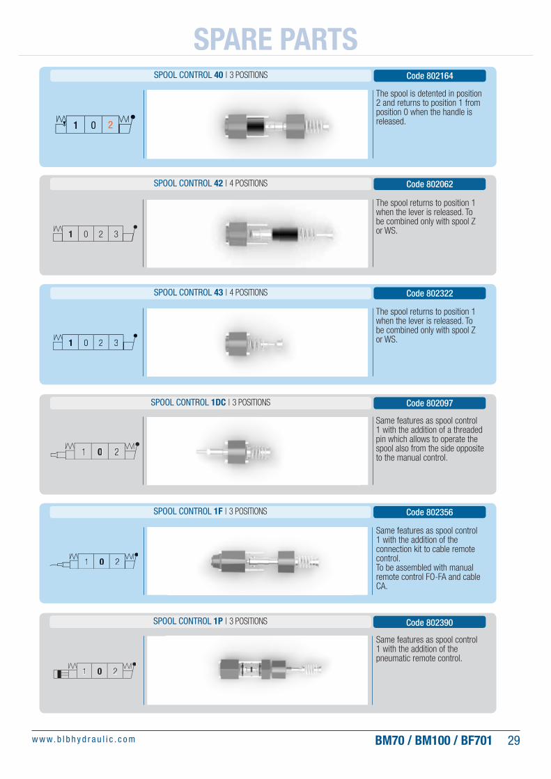
SPOOL CONTROL 40 | 3 POSITIONS
The spool returns to position 1 when the lever is released. To be combined only with spool Z or WS.
SPOOL CONTROL 42 | 4 POSITIONS Code 802062
Code 802164
The spool returns to position 1 when the lever is released. To be combined only with spool Z or WS.
SPOOL CONTROL 43 | 4 POSITIONS Code 802322
Same features as spool control 1 with the addition of a threaded pin which allows to operate the spool also from the side opposite to the manual control.
SPOOL CONTROL 1DC | 3 POSITIONS Code 802097
Same features as spool control 1 with the addition of the pneumatic remote control.
SPOOL CONTROL 1P | 3 POSITIONS Code 802390
Same features as spool control 1 with the addition of the connection kit to cable remote control. To be assembled with manual remote control FO-FA and cable CA.
SPOOL CONTROL 1F | 3 POSITIONS Code 802356
SPARE PARTS
1 0 32
1 0 2
1 0 2
1 0 2
1 0 32
1 0 22

BM70 / BM100 / BF70130 w w w. b l b h y d r a u l i c . c o m
Same features as spool control 1 with the addition of a waterproof microswitch operating in position 1.
SPOOL CONTROL 1MSW1 | 3 POSITIONS Code 802263
Same features as spool control 1 with the addition of a waterproof microswitch operating in position 2.
SPOOL CONTROL 1MSW2 | 3 POSITIONS Code 802264
The electro-pneumatic control is used on vehicles equipped with compressed air system.
SPOOL CONTROL 1EP | 12 V Code 801557
The electro-pneumatic control is used on vehicles equipped with compressed air system.
SPOOL CONTROL 1EP | 24 V Code 801558
SPOOL CONTROL 1MSW0 | 3 POSITIONS Code 802262
Same features as spool control 1 with the addition of a waterproof microswitch operating in positions 1 and 2.
SPARE PARTS
1 0 2
M S W 1
1 0 2
1 0 2
M S W 2
1 0 2
1 0 2
M S W 0

BM70 / BM100 / BF701 31w w w. b l b h y d r a u l i c . c o m
Same features of spool control 1 with the addition of a stroke limiter.
SPOOL CONTROL 1MLAB Code 802439
Kit spool control with DACROMET protection against the marine corrosion. It’s used with the rotary actuator.
See page 19 for the characteristics of the rotary actuator.
KIT SPOOL CONTROL 8(DN) (BM100 ROTATIVO) Code 802267
Automatic release adjustable from position 1.
SPOOL CONTROL 2AKO | 3 POSITIONS Code 802269
SPARE PARTS
1 0 2
1 0 2
1 0 2201

BM70 / BM100 / BF70132 w w w. b l b h y d r a u l i c . c o m
CLOSED CENTER PLUG CCP - 3/4" BSP
Code 832013
CLOSED CENTER PLUG CCP - 1.1/16" - 12 UNF
Code 832035
CARRY OVER PLUG (POWER BYOND) CO - 3/4" BSP
Code 832160
CARRY OVER PLUG (POWER BYOND)CO - 1.1/16" - 12 UNF
Code 832034
Fittings and plugs
Turns an open center circuit into a closed center one. BSP threaded.
Turns an open center circuit into a closed center one. UNF threaded.
Allows the installation of another valve downstream the �rst. To be assembled on T2 port. BSP threaded.
Allows the installation of another valve downstream the �rst. To be assembled on T2 port. UNF threaded.
SPARE PARTS
A
A
CCPB
B
COA
A
CCP

BM70 / BM100 / BF701 33w w w. b l b h y d r a u l i c . c o m
P - BM70 / BF701T - BM70 / BF701
A / B - BM70 / BF701
PLUG 1/2" BSP - Code 015007 PLUG 7/8"-14 UNF - Code 015004
PLUG 1.1/16-12 UNF - Code 015005
Inlet / Outlet / Ports
P - BM100P2 - BM70 / BM100 / BF701
T - BM100T2 - BM70 / BM100 / BF701
A / B - BM100
P - BM70 / BF701T - BM70 / BF701
A / B - BM70 / BF701
PLUG 3/4" BSP - Code 015010
P - BM100P2 - BM70 / BM100 / BF701
T - BM100T2 - BM70 / BM100 / BF701
A / B - BM100
SPARE PARTS
B
B
A
ASEZ. B-B
SEZ. A-A
P2
A
B
T2
B
B
A
A
SEZ. B-B
SEZ. A-A
P
A
B
T

BM70 / BM100 / BF70134 w w w. b l b h y d r a u l i c . c o m
INSTRUCTIONS
DESCRIPTIONThe purpose of BM70, BM100 and BF701 is to direct the �ow circulating in the hydraulic systems, towards the user chosen by the operator (directional spool valves). The function is obtained by moving the spool within a cavity in a controlled and sequential way and opening ori�ces that, connecting with each other, realize the functional circuits. Functional and construction characteristics are shown in the initial part of the catalogue.
CHOICE AND USEBefore you choose the correct con�guration of BM70, BM100 and BF701 You must identify:
• Performance (pressure, �ow, temperature, reliability).• Functional characteristics of each BM70, BM100 and BF701. • Section and hydraulic diagram, actuators and controls.• The machine in which it is built-in (installation, accessibility,
connection of the hoses, tank, �lter).
The choice must be made so that BM70, BM100 and BF701 are used within the performance limits listed in the catalogue and in compliance with the operating conditions given in the table below.
HYDRAULIC FLUIDMINERAL OIL ACCORDING TO DIN 51524
VISCOSITYField 10 ÷ 460 mm²/sec
Optimal 12 ÷ 75 mm²/sec
TEMPERATUREExcursion -20 ÷ +80 °C
Optimal +30 ÷ +60 °C
MAXIMUM CONTAMINATION LEVEL (Filtro 25 μ ass. β
x= 75)
NAS 1638: CLASS 9 – ISO 4406: 20/19/16
ROOM TEMPERATURE -30 ÷ +60 °C
PRESSURE AND FLOW SEE CATALOGUE
PRESSURE DROP SEE CATALOGUE
OIL VELOCITY IN THE TUBES: INLET AND PORTS
6 ÷ 8 m/sec
OIL VELOCITY IN THE TUBES: RETURN
3 ÷ 4 m/sec
For all uses in which functional and performance conditions are not referable to this catalogue, please get in contact with BLB technical department. In case of permitted uses ask for written answers and additional speci�cations relevant to use.
SPECIAL PRODUCTSBM70, BM100 and BF701 are characterized by a high number of possible functional combinations. Products with high customization and combinations might not be identi�able in the catalogue.For such products, BLB provides the necessary advice to identify the optimal functional composition and supplies the documentation required for the installation and proper use.
USEAuthorized use.All applications that meet the speci�cations described in the sections “TECHNICAL FEATURES” and “CHOICE AND USE.”
Unauthorized use.• Do not use BM70, BM100 and BF701 in systems without
�ltration.• Do not use BM70, BM100 and BF701 with �uids other than
those listed in the table.• Do not use BM70, BM100 and BF701 to hold actuators in
a �xed position for periods of time not compatible with the working pressure. It is strictly prohibited to use BM70, BM100 and BF701 as an holding tool. In all cases in wich 0 leakage is required, auxiliary valves, speci�c for the purpose, have to be installed directly on the actuators.
SAFETY STANDARDSThe surfaces of BM70, BM100 and BF701 have sharp edges and internal cavities with residual oil. Therefore, during handling operations for storage, control, installation or demolition, testing, maintenance, and disposal it is necessary to:
• Grab the pieces with protective gloves.• Wear appropriate work clothes and non-slip work shoes.• Verify the size and weight to use suitable handling equipment.• Consult the handling mode (see section “Handling and Storage”).
IDENTIFICATION AND PACKAGINGBM70, BM100 and BF701 valves are delivered in closed single boxes or packages with variable sizes and weights. Each BM70, BM100 and BF701 valve is identi�ed by a label reporting a 6-digit code and a short description of the product, as well as the production lot or in alternative a laser mark containing the same information.

BM70 / BM100 / BF701 35w w w. b l b h y d r a u l i c . c o m
INSTRUCTIONS
CHECKS UPON RECEIPTUpon delivery, please check that:
• Packaging and products have not been damaged during shipping.• The supply is in accordance with the order.• Accompanying documents are complete and comprehensive.
In case non-conformity or failures are noticed, notify BLB within eight days from receipt date.
WARNINGS: BM70, BM100 and BF701 valves are delivered in oil-proof plastig bags. The internal cavities contain residual oil retained by the protective caps on ports.Remove the plastic caps only when the connection hoses have to be assembled.
HANDLING AND STORAGEBefore moving the products it is important to be aware of the size and weight to be moved.BM70, BM100 and BF701 valves, should be moved carefully and with adequate means for the size and weight of the package, whether it is a single pack or multi pack. It is necessary to take every precaution measures to prevent damage that could compromise the functional ef�ciency of the products and the safety of anyone present in proximity of the areas in which you operate.All BLB products need to be stored in a dry place, protected from weathering and possible damages.When the secondary packaging is removed, BM70, BM100 and BF701 valves should be stored with the oil-resistant protective bags.
INSTALLATIONBefore installing the products, you must check that they have not been damaged during internal handling and storage operations. In case of long storage before usage, please check that the products are complete with all their parts as originally delivered. In particular, for BM70, BM100 and BF701 valves, check that the protective caps have not been removed. In all cases in which the proper operation of the valve is doubtful, make proper tests on bench and replace those parts found faulty (oxidized, damaged, etc…).In case of any uncertainty or doubt please contact an authorized BLB service centre.Make sure that the system characteristics are those laid down in the project (�ltration, oil type and viscosity, temperature control, tank capacity, etc ...).
IMPORTANT: the installation of BM70, BM100 and BF701 calls for tightening of screws, �ttings and hoses. For each of these elements, you must use the appropriate tools and wrenches that allow the control of the tightening torque. Excessive tightening causes deformations to the valve, compromising the correct operation of the same. A weak tightening may affect the functionality and safety. Use the following table to determine the correct tightening torque for each element. Do not use provisional extension and do not act with bumps on the wrenches.
PART THREAD Nm
Fixing screws BM70/100, BF70 M10 x 1,5 8.8 45
Connectors/Plugs1/2" G ; 7/8" -14 UNF2B 50; 55
3/4" G ; 1" 1/16-12 UNF2B 95; 100
Valves, plugs VL80 M24 x 1,5 80
BM70, BM100 and BF701 installation procedures consist of 3 steps:
First step: valve �xing.Prepare the area where BM70, BM100 and BF701 will be placed, in order to ease the assembly, the hose connection and the adjustments during start-up and testing.Install the valve in shock and vibration-free areas.While moving the valve do not cause accidental bumps or shocks and follow the indications listed in the “HANDLING” paragraph.The valve must be secured with M10 screws through the holes provided. Apply thread-lock accessories.The mounting position is irrelevant as long as the valve is resting on a rigid and perfectly �at surface.This is necessary so that the tightening of the screws does not cause harmful deformation.

BM70 / BM100 / BF70136 w w w. b l b h y d r a u l i c . c o m
Second step: hydraulic hoses connection (inlet, ports, tank).Use hoses and �ttings suitable for indicated max �ow and pressure. It is strictly prohibited the usage of conic �ttings and the reversal of connections between inlet (P, P2) and tank (T, T2) lines.Remove protective plugs from the valve ports just before connecting the hoses to prevent contamination of the circuit with dust or other materials. Do not use tape wrapped on threads to seal. Tighten the �ttings with the torque indicated in the table.
Third step: Sytem startingBefore starting, “wash the system” by �uxing oil from an auxiliary system. Start the system and then operate the actuators individually and not under load.Operate slowly until the system is �lled with oil. Set the relief valves and carry out a complete testing of the system. In case the initial �uxing is not possible, clean the �lters at the end of testing.Do not perform calibration of valves without having �rst applied a pressure gauge on the inlet section of the valve and on line where deemed necessary.
MAINTENANCERoutine Maintenance• Periodically check the functionality of the relief valve of BM70,
BM100 and BF701.• Periodically clean the �lters of the system. Excessive oil
contamination causes irregular operation of the spool and of the relief valve.
Preventative maintenance• At each oil change of the system replace the �lters.• Check the calibration of the pressure relief valve and replace if
deemed no longer reliable.
Unscheduled maintenanceIn case of interventions for which it is necessary to disassemble the valve, consult BLB authorized service centers.
DEFECTIVENESS AND DISMANTLING
DefectivenessBM70, BM100 and BF701 valves are delivered tested. Defectiveness found during the initial installation generally derive from failing to comply with the directions outlined or for damages suffered during transportation. During the operating time of BM70, BM100 and BF701 valves it is possible to notice the following defectiveness.
Spool sticking
CAUSE CORRECTIVE ACTION
Excessive working pressureCheck the working pressure and the valves settings. Eliminate water hammer (pressure peaks).
Excessive oil contaminationReplace oil and �lters. Wash the system with auxiliary �uxing. Carry out maintenance at shorter intervals.
Valve not suitable for theapplication
Check and in case review the choice of the valve.
Additional controls andactuators
Check or change the additionalactuators.
Over-tightening of the �xingscrews
Loosen �ttings and fastening screws.
Support base with severegeometric errors (not �at)
Adopt additional brackets or elasticelements.
Excessive workingtemperature
Check the valves setting and the pressure drops of the system.
Oil leakage at the spool
CAUSE CORRECTIVE ACTION
Excessive working temperature
Increase the amount of oil in the system (by increasing the tank size).Decrease the pressure drop in the system.Improve the oil cooling.Check or change the valves setting.Replace seals or complete relief valves.
Excessive oil pressureCheck the working pressure and the valves settings.Eliminate water hammer (pressure peaks).
Valve not suitable for theapplication
Check and in case review the choice of the valve.
Seals worn or broken Replace the seals.
Excessive �ow for thevalve
Loosen �ttings and fastening screws.
Backpressure on tank line
Check for possible tight spots towards tank.
INSTRUCTIONS

BM70 / BM100 / BF701 37w w w. b l b h y d r a u l i c . c o m
Excessive internal leakage
CAUSE CORRECTIVE ACTION
Excessive working pressureCheck the working pressure and the valves settings.Eliminate water hammer (pressure peaks).
Excessive temperature of oilImprove the oil cooling.Check or change the valves setting.Replace seals or complete relief valves.
Unsuitable application Check and in case review the choice of the valve.
Valve seals worn or broken Replace seals or complete relief valves.
Spare partsThe spare parts available are shown in this catalogue. Replace the parts to be changed only with original spare parts. To correctly perform any replacements, comply with the relevant technical speci�cations (sheets, assemblies, bill of materials, procedures) provided by Blb.
DismantlingBM70, BM100 and BF701 valves no longer usable must be disassembled to split the parts constituting them. Separate the metal parts from those in synthetic material or rubber. Do not dispose part and the residual oil in them contained in the environment.
WARRANTY AND LIABILITY LIMITSBLB products are exclusively appointed to professional operators and users. Therefore, in warranty topics, it is not applied the discipline of Decree-Law no. 24 of 02-02-2002 in performance of European Directive 1999/44/EC.
All products are warranted for a period of 12 (twelve) months from date of shipment from BLB to be free from defects in materials and workmanship under:
• Correct use.• Normal operating conditions.• Proper application.
BLB’s obligation under this warranty is limited, at BLB’s option, ex-factory, to the repair or exchange, of any BLB product or part, which proves to be defective as provided herein.BLB reserves the right to either inspect the product at Buyer’s location or require it to be returned, free of charge, to the factory for inspection.Any description of goods, including any reference to Buyer’s speci�cation and any description in catalogues, circulars and other written material published by BLB is for the sole purpose of identifying the products and does not create an express warranty that the goods conform to the sample or model.Buyer is the sole responsible for determining the suitability of goods sold hereunder for Buyer’s use.
BLB reserves the right to discontinue, modify or revise the speci�cations of the products described herein. All details and components may vary depending on the installation. The above warranty does not extend to all parts typically subjected to sliding or rolling friction and wear. The warranty is also excluded on parts potentially subjected to oxidation or corrosion if not properly used or maintained.
The above warranty does not extend to goods damaged or subjected to accident, abuse or misuse after shipment form BLB’s factory nor to goods altered or reapired by anyone other than authorized BLB’s representatives.
BLB will in no event be liable for any incidental or consequential damage nor for any sum in excess of the price received for the goods for which liability is claimed. Equipment manufactured by third parties and included in the supply together with the material produced by BLB are subjected to the warranty conditions of the parts producer.
BLB is not subjected to warranty obligations on breakdowns, damages, malfunctions, failures, or inef�ciency resulting from wrong installation, intentional or unintentional tampering, poor maintenance, negligence or incompetence of the end user.Modi�cations or repairs carried out by people not speci�cally authorized in writing by BLB will invalidate the warranty.Late or non-payment, even partial, of the supplys cancels the warranty.
Warranty conditions do not confer to the customer the right to suspend or defer the payments which will have to be made in any case under the conditions agreed and speci�ed in the BLB order con�rmations. BLB reserves the right to cancel the warranty if:
• Labels or tags with the producer mark, product code and serial number have been deleted or removed.
• The product has been modi�ed or machined without express authorization given by BLB.
• The product has not been used in accordance with the instructions provided or for purposes other than those for which it has been designed.
Warranty is recognized only to BLB’s direct customers. Anyone in possession of BLB products, which however have been bougth through third parties (distribuotrs, dealers, installers or manufacturers of any kind), will have to contact the direct supplier for any eventual warranty claim.
THERE ARE NO EXPRESS WARRANTIES OTHER THAN THOSE SPECIFICALLY DESCRIBED HEREIN.The Court of Justice of BLB’s seat (Vicenza – Italy) is the only competent for any controversy.
TERMS & CONDITIONS OF SALEGeneral sales conditions may differ from Country to Country.BLB sales department will send all necessary information upon request. For anything not speci�ed herein, the norms of the Civil Code in matter apply.
INSTRUCTIONS

BM70 / BM100 / BF70138 w w w. b l b h y d r a u l i c . c o mBM70 / BM100 / BF70138 w w w. b l b h y d r a u l i c . c o m
NOTE

BLB S.r.l.Via Natta, 136040 Brendola (VI)Italy
T. +39 0444 401141F. +39 0444 401086W. www.blbhydraulic.comE. [email protected]
Nr 50 100 11533