upgrading of fire safety in nuclear power piants
TRANSCRIPT
XA9847498 -
IAEA-TECDOC-1014
III •
Upgrading of fire safetyin nuclear power piants
Proceedings of an International Symposiumheld in Vienna, 18-21 November 1997
IAEA29- 31
April 1998
The IAEA does not normally maintain stocks of reports in this series.However, microfiche copies of these reports can be obtained from
IN IS ClearinghouseInternational Atomic Energy AgencyWagramerstrasse 5P.O. Box 100A-1400 Vienna, Austria
Orders should be accompanied by prepayment of Austrian Schillings 100,in the form of a cheque or in the form of IAEA microfiche service couponswhich may be ordered separately from the IN IS Clearinghouse.

IAEA-TECDOC-1014
Upgrading of fire safetyin nuclear power plants
Proceedings of an International Symposiumheld in Vienna, 18-21 November 1997
W&jlf
n r\INTERNATIONAL ATOMIC ENERGY AGENCY
uLf-\
The originating Section of this publication in the IAEA was:
Engineering Safety SectionInternational Atomic Energy Agency
Wagramer Strasse 5P.O. Box 100
A-1400 Vienna, Austria
UPGRADING OF FIRE SAFETY IN NUCLEAR POWER PLANTSIAEA, VIENNA, 1998IAEA-TECDOC-1014
ISSN 1011-4289
©IAEA, 1998
Printed by the IAEA in AustriaApril 1998
FOREWORD
The lessons learned from experience in nuclear power plant operation indicate thatfires in nuclear power plants pose a real threat to nuclear safety and that their significanceextends far beyond the scope of a conventional fire hazard.
Considerable progress has been made over the past two decades in the design andregulatory requirements for fire safety, in fire protection technology and in related analyticaltechniques. Substantial efforts have been undertaken worldwide to implement these advancesin the interest of improving fire safety in both new and operating nuclear power plants.
Particular attention is being given to those nuclear power plants that were designed andconstructed according to earlier fire protection standards. Systematic examination of the firesafety of these plants is needed in order to identify the existing deficiencies and to implementappropriate corrective measures.
To assist in these efforts, the IAEA has initiated a project devoted to fire safety. Theproject, which commenced in 1993, concentrated mainly on the development of guidelines forexamining, item by item, the adequacy of overall fire safety arrangements for a plant.
This Symposium was intended to provide further assistance in enhancing the fire safetyof operating nuclear power plants. It served as a forum for the exchange of practicalexperience in the systematic assessment of fire safety at nuclear power plants and in thebackfitting process.
Various aspects of the upgrading of fire safety at nuclear power plants were discussedduring the Symposium, the second of its kind organized by the IAEA. The Symposiumcovered all relevant elements of the upgrading process: identification of fire safety relateddeficiencies, the search for the most appropriate corrective measures, and implementation ofselected engineering or organizational solutions. Various reviews of fire protection measures,a systematic analysis of fire safety at nuclear power plants, reporting and assessment of firerelated incidents and related databases, the regulatory approach to fire safety backfitting, andthe lessons learned from the implementation phase were the most important topics covered.
The IAEA is grateful to all those who helped to prepare the meeting, define its scopeand structure, select the papers and chair the sessions. It is hoped that the Proceedings willconstitute an important source of information to all those concerned with reducing fire risk atnuclear power plants.

EDITORIAL NOTE
In preparing this publication for press, staff of the IAEA have made up the pages from theoriginal manuscripts as submitted by the authors. The views expressed do not necessarily reflectthose of the IAEA, the governments of the nominating Member States or the nominatingorganizations.
Throughout the text names of Member States are retained as they were when the text wascompiled.
The use of particular designations of countries or territories does not imply any judgement bythe publisher, the IAEA, as to the legal status of such countries or territories, of their authoritiesand institutions or of the delimitation of their boundaries.
The mention of names of specific companies or products (whether or not indicated asregistered) does not imply any intention to infringe proprietary rights, nor should it be construedas an endorsement or recommendation on the part of the IAEA.
The authors are responsible for having obtained the necessary permission for the IAEA toreproduce, translate or use material from sources already protected by copyrights.
CONTENTS
FIRE SAFETY REVIEWS (Session 1)
The necessity of periodic fire safety reviews (IAEA-SM-345/30) 3
D.S. MowerFire protection assessment in a WANO peer review (IAEA-SM-345/26) 7
R. VellaS o m e i n s i g h t s f r o m fire risk a n a l y s i s o f U S n u c l e a r p o w e r p l a n t s ( I A E A - S M - 3 4 5 / 2 7 ) . . . . 17
M. Kazarians, J.A. Lambright, M. V. FrankOverview of IAEA guidelines for fire safety inspection and operation in nuclear power
plants (IAEA-SM-345/28) 25D.S. Mowrer
Lessons learned from IAEA fire safety missions (IAEA-SM-345/29) 39S.P. Lee
FIRE SAFETY ANALYSIS: METHODOLOGY (Session 2)
Fire safety analysis: Methodology (IAEA-SM-345/37) 49M. Kazarians
Fire risk analysis: A discussion on uncertainties and limitations (IAEA-SM-345/31) 55M. Kazarians, S. Nowlen
Research needs in fire risk assessment (Summary) (IAEA-SM-345/32) 65N. Siu, J.T. Chen, E. Chelliah
Fire PSA methodology (IAEA-SM-345/25) 69M. Fukuda, T. Uchida, Т. Микае, М. Hirano
The French fire protection concept. Vulnerability analysis (IAEA-SM-345/35) 77M. Kaercher
Pilot fire radius size and its variation regarding the uncertainty in fire risk assessment(IAEA-SM-345/2) 89J. Argirov
FIRE SAFETY ANALYSIS: APPLICATIONS (Session 3)
A fire hazard analysis at the Ignalina nuclear power plant (IAEA-SM-345/1) 99F. Jorud, T. Magnusson
Анализ влияния пожаров и их последствий на безопасный останов энергоблокас реактором ВВЭР-1000 (IAEA-SM-345/9) 105Г. Солдатов, В. Морозов, Г. Токмачев
Сравнительный анализ опасностей обычного и натриевого пожара на АЭСс быстрым реактором (IAEA-SM-345/36) 127В. Н. Иваненко, Д.Ю. Кардаш
Panel I: Identification of deficiencies in fire safety in nuclear power plants 139
OPERATIONAL EXPERIENCE AND DATA (Session 4)
Operational experience and data (IAEA-SM-345/40) 145M. Rowekamp
Состояние дел в области пожарной безопасности на АЭС России —
статистический анализ эксплуатационного опыта (IAEA-SM-345/39) 147В.Н. Давиденко, В. И. Погорелое, Г.Е. Солдатов
Development of a fire incident database for the United States nuclear power industry(IAEA-SM-345/38) 167G Wilfc
German data for risk based fire safety assessment (IAEA-SM-345/4) 173M. Rowekamp, HP. Berg
Estimation of fire frequency from PWR operating experience (IAEA-SM-345/6) 181R. Bertrand, F. Bonneval, G. Barrachin, F. Bonino
Criteria for classification and reporting of fire incidences in nuclear power plants ofIndia (IAEA-SM-345/5) 189R.K. Kapoor
Risks of turbine generators at VVER-440 nuclear power plants (IAEA-SM-345/7) 199T. Virolainen, J. Marttila, H. Aulamo
Panel 2: Experience based data in fire safety assessment 219
FIRE SAFETY REGULATIONS AND LICENSING (Session 5)
Fire safety regulations and licensing (IAEA-SM-345/43) 223HP. Berg
Fire safety regulations for nuclear power plants in Germany and the various dimensionsof German KTA standardization activities. Is there a benefit today?(IAEA-SM-345/11) 229R. Wittmann
Technical methods for a risk-informed, performance-based fire protection programat nuclear power plants (IAEA-SM-345/41) 239M.K. Dey
Industry participation in the development of a risk-informed, performance-basedregulation for fire protection at US nuclear power plants (IAEA-SM-345/42) 255F.A. Emerson
Регулирующая деятельность в области пожарной безопасности АЭС вРоссийской Феделации — законодательная база и опыт лицензирования(IAEA-SM-345/13) 263
В. И. ПогорелоеДеятельность Украинского регулирующего органа по обеспечению пожарной
безопасности энергоблоков АЭС Украины (IAEA-SM-345/48) 273Г. Ляденко
General fire protection guidelines for Egyptian nuclear installations(IAEA-SM-345/12) 283S.M. Rashad, A.Z. Hussein, F.H. Hammad

UPGRADING PROGRAMMES (Session 6)
Upgrading of fire protection arrangements at Magnox power stations inthe United Kingdom (IAEA-SM-345/14) 295L.H. Zhu
Состояние пожарной безопасности на атомных станциях вРоссийской Федерации и техническая политика Минатома Россиив области пожарной безопасности (IAEA-SM-345/15) 301В.А. Губанов, Н.И. Голов, Н.Н. Давиденко
Fire hazard assessment of CANDU plants (IAEA-SM-345/47) 315A. H. Stretch
Safety improvements made at the Loviisa nuclear power plant to reduce fire risksoriginating from the turbine generators (IAEA-SM-345/8) 323T. Virolainen, J. Marttila, H. Aulamo
Upgrading of fire safety in Indian nuclear power plants (IAEA-SM-345/45) 331N.K. Agarwal
Updating of the fire fighting systems and organization at the Embalse nuclearpower plant, Argentina (IAEA-SM-345/17) 345C.F. Acevedo
Cernavoda nuclear power plant: Modification in the fire protection measuresof the CANDU 6 standard design (IAEA-SM-345/19) 349
V. Covalschi
Integrated approach to fire safety at the Krsko nuclear power plant —Fire protection action plan (IAEA-SM-345/20) 355J.A. Lambright, J. Cerjak, J. Spiler, J. loannidi
Fire protection programme during construction of the Chashma nuclearpower plant (IAEA-SM-345/18) 367M. Mian Umer
Optimization of extinguishing agents for nuclear power plants (IAEA-SM-345/23) 371M. Boleman, M. Lipar, K. Balog
CLOSING SESSION
Current and future IAEA activities in the area of fire safety 379M.J. Kulig
Concluding statement 389G. W Jones
CHAIRPERSONS OF SESSIONS AND SECRETARIATOF THE SYMPOSIUM 393
LIST OF PARTICIPANTS 395
FIRE SAFETY REVIEWS
(Session 1)
Chairperson
U.H.S. SCHNEIDERAustria
la I -,'•: A 4K

IAEA-SM-345/30
Key Issues Paper
THE NECESSITY OF PERIODIC XA9847499FIRE SAFETY REVIEW
D.S. MOWRERHSB Professional Loss Control,Kingston, Tennessee,United States of America
1. INTRODUCTION
Nuclear power is clearly a very important commodity in the global community. And, as the1986 Chernobyl disaster demonstrated so clearly, fire events in nuclear plants can have far-reachingconsequences well beyond the plants' physical boundaries. We all share a grave responsibility toensure that a minimum level of fire safety is provided and maintained in nuclear power plants. Thisresponsibility can best be met by the continual, periodic monitoring of fire safety measures within theplants.
2. DETERMINING FIRE SAFETY LEVELS
Because each plant's resources are limited, the resources available for fire safety efforts mustbe allocated wisely. Various methods are available to the practicing fire safety engineer fordetermining how much fire safety is needed. One can approach the problem using basic engineeringjudgment. This subjective approach can result in wide variation in the level of fire safety achieved,depending on the experience of the engineer and the accuracy of his/her judgments. This is theapproach used by a number of plant designers years ago, before fire was identified as an event withsignificant potential for affecting nuclear safety. The reliance on individual engineering judgmentultimately resulted in levels of fire safety ranging from excessively conservative in some specificplant areas, to a fair overall level in some nuclear plants, to almost no fire safety in other plants.
In consequence, regulatory authorities have developed requirements to establish minimumlevels of fire safety which must be provided in nuclear plants. Some of these guidelines are broad,performance-based regulations while others are more prescriptive and offer few choices for thedesigner. Specific prescriptive-type codes and standards such as those published by the National FireProtection Association, the Loss Prevention Council, and others offer detailed requirements on thedesign and arrangement of specific elements of fire safety once a decision has been made to installpassive measures or active fire extinguishing systems.
More and more frequently during the past two decades, systematic fire safety analyses havebeen performed to determine the required level of fire safety in nuclear plants. The analysis oftentakes the form of a deterministic-type fire hazard analysis (FHA). This comprehensive document canbe either qualitative or quantitative in nature; usually it is a combination of the two approaches.Currently, fire safety analyses are being approached using the fire probabilistic safety assessment(PSA) method. This method, which identifies dominant risk contributors, often is used to supplementa deterministic FHA. It can be used as a means for comparing options for risk reduction based on theprobability of a specific initiating event leading to a fire of a magnitude sufficient to result in coredamage. By screening out less significant events, this method focuses attention on those events whichhave the highest probability of affecting plant nuclear safety. The broad goal of each method is toensure nuclear safety for the plant. As the analytical methods in use increase in sophistication andlevel of detail, one expects that the level of safety will also increase and that the scarce resourcesavailable for fire safety will be utilized more efficiently.
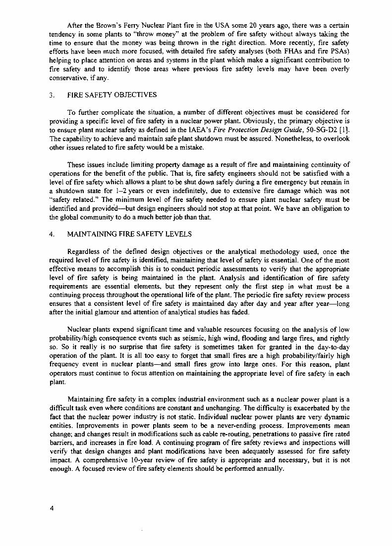
After the Brown's Ferry Nuclear Plant fire in the USA some 20 years ago, there was a certaintendency in some plants to "throw money" at the problem of fire safety without always taking thetime to ensure that the money was being thrown in the right direction. More recently, fire safetyefforts have been much more focused, with detailed fire safety analyses (both FHAs and fire PSAs)helping to place attention on areas and systems in the plant which make a significant contribution tofire safety and to identify those areas where previous fire safety levels may have been overlyconservative, if any.
3. FIRE SAFETY OBJECTIVES
To further complicate the situation, a number of different objectives must be considered forproviding a specific level of fire safety in a nuclear power plant. Obviously, the primary objective isto ensure plant nuclear safety as defined in the IAEA's Fire Protection Design Guide, 50-SG-D2 [1].The capability to achieve and maintain safe plant shutdown must be assured. Nonetheless, to overlookother issues related to fire safety would be a mistake.
These issues include limiting property damage as a result of fire and maintaining continuity ofoperations for the benefit of the public. That is, fire safety engineers should not be satisfied with alevel of fire safety which allows a plant to be shut down safely during a fire emergency but remain ina shutdown state for 1-2 years or even indefinitely, due to extensive fire damage which was not"safety related." The minimum level of fire safety needed to ensure plant nuclear safety must beidentified and provided—but design engineers should not stop at that point. We have an obligation tothe global community to do a much better job than that.
4. MAINTAINING FIRE SAFETY LEVELS
Regardless of the defined design objectives or the analytical methodology used, once therequired level of fire safety is identified, maintaining that level of safety is essential. One of the mosteffective means to accomplish this is to conduct periodic assessments to verify that the appropriatelevel of fire safety is being maintained in the plant. Analysis and identification of fire safetyrequirements are essential elements, but they represent only the first step in what must be acontinuing process throughout the operational life of the plant. The periodic fire safety review processensures that a consistent level of fire safety is maintained day after day and year after year—longafter the initial glamour and attention of analytical studies has faded.
Nuclear plants expend significant time and valuable resources focusing on the analysis of lowprobability/high consequence events such as seismic, high wind, flooding and large fires, and rightlyso. So it really is no surprise that fire safety is sometimes taken for granted in the day-to-dayoperation of the plant. It is all too easy to forget that small fires are a high probability/fairly highfrequency event in nuclear plants—and small fires grow into large ones. For this reason, plantoperators must continue to focus attention on maintaining the appropriate level of fire safety in eachplant.
Maintaining fire safety in a complex industrial environment such as a nuclear power plant is adifficult task even where conditions are constant and unchanging. The difficulty is exacerbated by thefact that the nuclear power industry is not static. Individual nuclear power plants are very dynamicentities. Improvements in power plants seem to be a never-ending process. Improvements meanchange; and changes result in modifications such as cable re-routing, penetrations to passive fire ratedbarriers, and increases in fire load. A continuing program of fire safety reviews and inspections willverify that design changes and plant modifications have been adequately assessed for fire safetyimpact. A comprehensive 10-year review of fire safety is appropriate and necessary, but it is notenough. A focused review of fire safety elements should be performed annually.
5. BENEFITS OF PERIODIC FIRE SAFETY REVIEWS
What benefits can be expected from performance of periodic fire safety reviews? These annualassessments will verify the operability of extinguishing systems whose function has been determined(through the FHA and/or fire PSA) to be critical to plant nuclear safety. The assessments will ensurethat the combustible fire load does not exceed the level identified in the FHA. They will verify thatthe plant's fire prevention program is effective in controlling potential sources of ignition. They willalso document the level of manpower, equipment and training provided by the fire brigade and assessthe brigade's state of readiness for fire response.
Two examples will serve to illustrate the value of periodic fire safety reviews. The firstexample involves the case of a nuclear plant where it was determined that a fire extinguishing systemwas necessary to protect the bearings of the turbine generator. A carbon dioxide system was designed,installed, and maintained to satisfy the requirement. During a subsequent periodic fire safety review,the inspector noted that the carbon dioxide system was arranged to discharge its extinguishing gasoutside the turbine shroud, rather than inside the enclosure where the majority of the oil hazardexisted. Obviously, this fire protection system was totally ineffective; and the time, money and effortof installing the system was largely wasted. Had an oil fire involving the turbine bearings developed,the thermal detectors associated with the carbon dioxide system could have activated, uselesslydischarging the system's gas into the large turbine building, while the lubricating oil continued toburn inside the turbine shroud and also spread onto the floor below via unprotected floor openings.
In another example, an interior standpipe system (or rising main) was installed in the reactorbuilding of a nuclear plant for use by the fire brigade. During a periodic fire safety review, one of thefire hoses was chosen at random to verify the water flow available for fire brigade use. The controlvalve was opened, and an acceptable flow of water discharged from the nozzle for about 30seconds—and then slowed to a bare trickle. Upon closer examination, it was discovered that thenozzle was totally blocked by clam shells. The plant obtained its water supply from an open watersource (a river) which recently had become infested by Asiatic clams. These clams had entered thefire protection piping system and thrived. Fortunately, by discovering this problem during theperiodic fire safety review, the plant was able to evaluate the situation, take appropriate action, andsolve the problem prior to using the standpipe system in an emergency fire situation.
In addition to valuable troubleshooting, another immediate benefit of a fire safety review is thefree and open exchange of fire safety knowledge and ideas between the fire safety assessor and theplant staff. Open communication should be encouraged at all levels of the plant. The intent of thereview is definitely not to find fault nor to assign blame to a specific individual or group. Plant staffshould be encouraged not to be defensive or worried that the assessor will identify a problem in theirwork area. An adversarial atmosphere is counterproductive. The atmosphere should be one whichheightens fire safety awareness of plant staff and which promotes lively discussion on ways toimprove fire safety. To be sure, one important objective of the fire safety review is to verify that thelevel of fire safety identified in design basis documents (such as the FHA, fire PSA, or the final safetyanalysis report) is being maintained. However, the overall intent of the review is to improve firesafety for the plant, not to take a narrow, legalistic approach which finds satisfaction in exposingdeficiencies. The reviewer should make every effort to maximize the benefit to the plant, whileminimizing any adverse effects on plant operations.
When problem areas are identified, they should be considered seriously and addressedpromptly. A periodic fire safety assessment can identify small problems when they are not especiallysignificant to nuclear safety, before they grow into crisis situations. On occasion, the management ofa nuclear plant will mistakenly assume that the only correct resolution to fire safety problems is toestablish a new working committee or administrative division, resulting in a virtual mountain ofpaperwork and documentation. Resolution of fire safety deficiencies may entail a certain amount of

paperwork (after all, this is the nuclear power business). However, the intent of periodic fire safetyreviews is not to create a paperwork nightmare; it is, quite simply, to improve fire safety.
Years of experience in performing fire safety reviews in nuclear power plants indicate that theinitial one or two inspections at a plant will likely result in a number of findings. Some of these willbe significant to plant nuclear safety, and many others will be of a minor nature. Subsequentinspections at the same plant usually show a marked reduction in findings (both in quantity andsignificance). Even so, such periodic reviews provide valuable assistance to the plant in continuing toimprove the overall level of fire safety year after year.
6. FIRE SAFETY REVIEW PROCESS
The fire safety review should begin with a review of records and documentation. Thisdocumentation includes design basis documents such as the FHA and fire PSA, administrativeprocedures and policies related to the fire prevention program, and plant arrangement drawings.Discussion with plant staff at all operating levels is an important element throughout the reviewprocess. Maintaining open channels of communication is critical to allowing free exchange of ideasand information. Finally, an essential element of the review process is to conduct a field walkdown ofaccessible plant areas. The importance of this phase of the process cannot be overstated. Review ofpaperwork is necessary but should never be considered a substitute for visual observation in the field.Fully 30%-40% of the time allocated to the fire safety review should be spent in the field looking atactual plant conditions and talking directly with plant engineers, operators, maintenance staff, and firebrigade personnel.
It is important to recognize that effective fire safety reviews do not have to involve a majortime commitment. A full-scale review of all elements of fire safety at a nuclear plant should requireonly about 100-200 manhours (for example, two engineers on site for two weeks each). An annual in-house review by qualified plant staff can be effective; however, occasional review by an independent,outside expert can bring in a fresh perspective. This independent review should be considered atintervals not exceeding 3-5 years.
The key to minimizing time and maximizing effectiveness of fire safety reviews is to choosepersonnel who are highly qualified and experienced. This is essential whether using in-plant staff oroutside consultants. An option which provides a new, fresh perspective at a reasonable cost to theplant is to make arrangements with another nuclear plant to "trade" fire safety personnel for thepurpose of conducting an independent review. This approach can be very effective in the exchange ofnew ideas and technology while at the same time meeting the need for an independent fire safetyreview at no additional cost to the plant.
7. SUMMARY
Effective fire safety requires the coordinated integration of many diverse elements. Clear firesafety objectives are defined by plant management and/or regulatory authorities. Extensive and time-consuming systematic analyses are performed. Fire safety features (both active and passive) areinstalled and maintained, and administrative programs are established and implemented to achieve thedefined objectives. Personnel are rigorously trained. Given the time, effort and monetary resourcesexpended to achieve a specific level of fire safety, conducting periodic assessments to verify that thespecified level of fire safety has been achieved and is maintained is a matter of common sense.Periodic fire safety reviews and assessments play an essential role in assuring continual nuclear safetyin the world's power plants.
REFERENCE
[1] INTERNATIONAL ATOMIC ENERGY AGENCY, Fire Protection in Nuclear Power Plants:A Safety Guide, IAEA Safety Series No. 50-SG-D2 (Rev. 1), IAEA, Vienna (1992).
IAEA -SM-345/26
Invited Paper
FIRE PROTECTION ASSESSMENT IN A WANO PEER REVIEW
R. VELLAWorld Association of Nuclear Operators, Paris, France '"""9847500
Abstract
The peer review programme is becoming the key programme of WANO. The reviews areconducted to assess the performance of plant personnel, the conditions of systems and equipment, thequality of programmes and procedures, and the effectiveness of plant management. The review teamconsists of highly qualified staff from other WANO members throughout the world who haveextensive practical experience in the area the review. At the request of Paris Centre Members, the fireprotection area has been added to the scope of WANO peer reviews. Relevant performance objectivesand criteria have been developed to cover this area, these are written guidances upon which review ofplant performance can be based. They are supported by criteria, more narrow in scope, to help furtherdefine what attributes of the fire protection management area contribute to the achievement of theassociated performance objective.
The driving force to establish WANO came from the accident at the Chernobyl Nuclear powerplant in 1986.
This accident made nuclear operations aware of the need for international co-operation andthe exchange of information.
WANO's mission is to maximise the safety and reliability of the operation of nuclear powerplants by exchanging information and encouraging communication, comparison andemulation amongst its members.
Membership of WANO is open to all companies that operate electricity producing nuclearpower plants and organisations representing nuclear operators.
Membership is entirely voluntary. Every single organisation in the world that operates anuclear electricity generating power plant has chosen to be a member of WANO.
WANO is non profit making and has no commercial ties. It is not a regulatory body. It doesnot advise on design issues and it is neither a funding agency nor a lobbying organisation.
In short, WANO has no interests other than nuclear safety.
WANO operates five main programmes which form the basis of its activities:
• The Operating Information Exchange Programme
• The Operator to Operator Exchange Programme• The Performance Indicator Programme• The Good Practices Programme• The Peer Review Programme
Each programme is designed to support the WANO mission and provide practical help tomembers.

I. THE PEER REVIEW PROGRAMME
The merit of periodically reviewing company operations by outside organisations or teams,already acknowledged in other industries, has been now developed by WANO within thenuclear electric power industry.
WANO peer reviews are voluntary and are performed at the request of a member: Utility orPlant.
The reviews are conducted to assess the performance of plant personnel, the conditions ofsystems and equipment, the quality of programmes and procedures and the effectiveness ofplant management.
The focus is on plant safety and reliability.
The following areas are normally reviewed:
• Organisation and Administration
• Operations• Maintenance• Engineering Support• Training and Qualification• Radiological Protection• Chemistry• Operating Experience
The review team consists of highly qualified staff from other WANO members throughout theworld who have extensive practical experience in the area they review. They bring togetherknowledge and experience of operating plants in different countries, and make an objectiveassessment of the operations of the plant reviewed against best international practice.The review aims at identifying weaknesses, shortfall and their root causes. Suggestions tohelp the host plant in addressing and fixing problem can be made when enough expertise andknowledge are available among the team. It is then up to plant to make use of them or not.
Performance objectives and criteria have been developed to cover each area. These are writtenguidances upon which review of plant performance can be based. The performance objectivestates, in broad terms, what excellence in performance means for the specific managementarea. Excellence used in this context is not perfection, but is a dynamic performance goal thatis always higher than the present level of performance.
The criteria are results-oriented. The methods for achieving the desired results are generallynot stated. Thus considerable judgement is required in applying the criteria.
These performances objectives and criteria and the large international cross experience ofWANO reviewers, serve as the review standard.
II . FIRE PROTECTION - REVIEW
Fire hazard is always considered as a significant risk in all industries. In a nuclear power plantthis risk represents through its potential consequences a major threat to nuclear safety.

Therefore at the request of several members of the Paris Centre, this area was recently addedto the scope of Paris Centre Peer Reviews.
A group of Experts from different utilities have contributed to set down the relevantperformance objectives and criteria.
They will be used for the first time during two reviews which are under process at Doel andHartlepool NPPs.Fire Protection organisation, potential fire hazard, control of combustibles materials andignition sources, Inspection, Maintenance and Test for both passive and active fire protectionmeasures, Training and Knowledge will be reviewed.
After those two pilot Peer Reviews in the area of Fire Protection, the experience gained duringthis first implementation will be integrated as feedback in the next version of the PO and C.
HI FIRE PROTECTION - PERFORMANCE OBJECTIVES AND CRITERIA
The Fire Protection area has been divided into the six following specific management areas:
FP. 1 Fire Protection Organisation and AdministrationFP.2 General Employee Knowledge in Fire ProtectionFP.3 Fire Protection Surveillance, Testing and Maintenance ProgrammeFP.4 Fire Protection Work PracticesFP.5 Fire Protection Facilities and EquipmentFP.6 Fire Protection Personnel Knowledge and Performance
For each of those specific management areas, a performance objective is assigned.
Since, the performance objective is a broadly stated goal, achievement of the intent of theperformance objective is desired. Therefore, criteria are assigned to each performanceobjective to help further define what attributes of that management area contribute to theachievement of the performance objective. The criteria that support each performanceobjective are more narrow in scope than the performance objective and typically describe aspecific activity.
Since it is impossible to give a complete description of each performance objective andsupporting criteria, one performance objective will be described. The concepts are similaramong the other performance areas.
The following is the management area "Fire Protection Organisation and Administration", theperformance objective and the associated criteria.
The performance objective states in broad terms:
"Fire Protection organisation and administration ensure effective implementation and controlof fire protection activities".
Criteria associated with this performance objective state for example that the organisationalstructure should be clearly defined; staffing and resources should be adequate to accomplish

assigned tasks, responsibilities and authorities should be clearly defined, personnel shouldunderstand their authorities and responsibilities, adequate training be insured.
Criteria also address management and supervisory involvement and attitude, contractors tasksresponsibilities, authorities interfaces and co-operation between the various stakeholders.
However, the criteria listed are not intended to address every activity associated with theperformance objective. Meeting all the listed criteria does not necessarily ensure that theperformance objective is fully met. Conversely, a nuclear plant may effectively achieve theperformance objective without meeting each specific criterion.
Therefore, it has to the emphasised that a plant should maintain a broad perspective andconcentrate on achieving the intend of the performances objectives rather than focusing solelyon the supporting criteria.
IV. FIRE PROTECTION - GUIDELINES
The Criteria associated with the Performance Objectives should not be considered as a checklist.
The extensive practical experience, the knowledge and experience of all the peer review teammembers coming from different countries around the world will of course be used together tomake an objective assessment against best international practices.
In addition, reviewers are asked to take advantage of publications of international bodies like:
- The Safety Guide of IAEA No. 50 SG D2, and
- The International Guidelines for the fire protection of nuclear power plants published onbehalf of the national nuclear risks insurance pools and associations.
Lastly the reviewers are provided with guidelines for specific plant areas. Areas presenting ahigher fire hazard or where the consequences of a fire are severe, need to be more deeplyexamined.
Here after are some examples:
1) In the main Control Room
Points that need particular attention:
- Fire protection equipment must not jeopardise the safety of the control room personnel(Carbon dioxide flooding system...)
- Fire hose reels and extinguishers close to the access- Fire resistance rating (partitions, cables)- Smoke dampers in ventilation systems, isolation of recirculation system- Fire detection panel (presence of alarm, alarm sheets)
10
- Smoke detectors in the control room, cabinets and in the ventilation intake- Breathing apparatus and protective clothes- Combustible materials (carpeting, desk...).
The control room is generally the point of contact in case of fire. Therefore operatorsshould be interviewed on:
- What are the criteria and means to call the internal and/or external fire brigade?
- What information must they communicate to the fire brigade?
The answers should be checked against the plant documentation and relevant procedures.
2) In the Electrical Room
A particular attention must be paid to the following rooms:
- Cable spreading room
- Plant computer rooms- Switchgear rooms- Safety-related battery rooms- Galleries.Some elements to observe are:
- In battery rooms: the ventilation (limit the hydrogen concentration and resistant tocorrosive products), explosion proof lighting
- Fire compartment integrity (electrical and mechanical penetrations, gutters with hydraulicseal...)
- Posting and labelling (fire penetrations, fire doors, etc. well identified, emergency exitsand escape routes clearly marked...)
- Phones in the vicinity
- Local detection cabinets and portable extinguishers located outside the protected area.
Conclusion
The Performance Objectives and Criteria provide a good support to define the scope of thereview.
The guidelines are more like generic lists which must be completed to take into accountspecificity of the plant.
All this information is provided to the team members in advance of the review together withdocumentation relevant to the plant to be reviewed.
11

PERFORMANCE OBJECTIVES & CRITERIA
FIRE PROTECTION
FP. 1 FIRE PROTECTION ORGANISATION AND ADMINISTRATIONFP.2 GENERAL EMPLOYEE KNOWLEDGE IN FIRE PROTECTIONFP.3 FIRE PROTECTION SURVEILLANCE, TESTING AND MAINTENANCE
PROGRAMFP.4 FIRE PROTECTION WORK PRACTICESFP.5 FIRE PROTECTION FACILITIES AND EQUIPMENTFP.6 FIRE PROTECTION PERSONNEL KNOWLEDGE AND PERFORMANCE
FP1
FIRE PROTECTION ORGANISATION AND ADMINISTRATION
PERFORMANCE OBJECTIVEFire protection organisation and administration ensures effective implementation and controlof fire protection activities.
CRITERIA
A. The organisational structure is clearly defined.
B. Staffing and resources are sufficient to accomplish assigned tasks.
C Responsibilities and authorities of all plant personnel involved in Fire Protection(including co-ordination of on-site and off-site fire fighting preparedness) are clearlydefined and understood. Authorities are commensurate with responsibilities. Personnelare held accountable for carrying out assigned responsibilities.
D. Contractor tasks, responsibilities, authorities, and interfaces are clearly defined andunderstood.
E. Interfaces with insurers and official Safety Organisations are clearly defined andunderstood. Action items and recommendations receive appropriate priority andapproval, and are scheduled and tracked to completion.
F. Interfaces with supporting groups, including headquarters organisations, are clearlydefined and understood.
G. Managers and supervisors demonstrate and require a conservative approach concerningFire Protection activities. High performance standards are established, communicatedand reinforced. Managers and supervisors
H. routinely observe activities to ensure adherence to station policies and procedures, andto identify and correct problems.
I. Administrative controls are effectively implemented for Fire Protection activities.
J. Contractors and other non station personnel use the same (or equivalent) approvedpolicies, procedures, control, and workmanship standards as station personnel.
12

K. Fire Protection problems and fire events are documented, evaluated and reported. Theseevaluations are reviewed for trends, and actions are taken to correct the causes.
L. Lessons learned from in-house fire event investigations and other industry operatingexperience are used to improve fire safety.
M. Personnel are actively encouraged to develop improved methods and a questioningattitude towards meeting safety, reliability and quality goals.
N. Fire Safety training programs are systematically evaluated and revised to ensure trainingis adequate and appropriate and that personnel are well trained.
O. Emergency plans for responding to fire are in place and are reviewed regularly for theirefficiency. The arrangements cover fire alone and fire occurring at the same time as anuclear accident
P- Modifications and design changes are reviewed appropriately to address the effects ofthe modification on fire safety. Staff assigned to undertake this activity are suitablyqualified and experienced.
FP2
GENERAL EMPLOYEE KNOWLEDGE IN FIRE PROTECTION
PERFORMANCE OBJECTIVEStation personnel, contractors and visitors have the knowledge necessary to implement fireprotection practices associated with their work in an effective manner.
CRITERIAA. Station personnel, contractors and visitors have a job-related fire protection knowledge
and practical abilities, especially regarding the following :
1. actions to reduce ignition sources and fire hazards during routine operations.
2. action to minimise the accumulation of combustible materials.
3. actions to be taken in the event of a fire.
4. action to control and avoid the spreading of a fire
B. Job-related knowledge and practical ability are maintained in the following areas:
1. Basic fire protection subjects
2. Pertinent changes in fire protection procedures
3. Lessons learned from in-house and industry operating experiences
C. Personnel are aware of the fire protection requirements for the jobs they perform. Hotwork permit procedures and their requirements are implemented on the jobperformance. Proficiency is demonstrated in using extinguishers, fire hose stations orinstalled fire fighting equipment.
13
FP3
FIRE PROTECTION SURVEILLANCE, TESTING AND MAINTENANCE PROGRAM
PERFORMANCE OBJECTIVESurveillance, testing and maintenance program ensure optimum performance and reliability.
CRITERIAA. Codes, regulations and standards applicable to the fire protection systems and
equipment are clearly understood.
B. All spurious fire alarms are reported and investigated. Deficiencies are corrected as soonas possible.
C. A comprehensive surveillance, maintenance and testing programme is established andimplemented to cover both active and passive fire protection features of the plant.
D. The frequency and scope of inspection, maintenance and testing activities areappropriate to the individual parts of the fire protection system and are in accordancewith best international practices.
E. Inspection, maintenance and testing activities are carried out by suitable qualified andexperienced staff.
FP4
FIRE PROTECTION WORK PRACTICES
PERFORMANCE OBJECTIVEStation fire protection work practices and conditions achieve a high degree of safety
CRITERIA
A. The use and storage of combustible materials (solids, liquids, gases) is minimised.Accumulations of transient combustible materials and wastes are controlled. Safepractices are used in the storage, handling, use and transportation of combustiblesubstances. Storage areas are routinely monitored and precautions are taken to limit thepotential consequences of a leakage (for example use of drip trays for combustibleliquids and sufficiently ventilated areas for flammable gases).
B. The use of ignition sources associated with hot work processes (cutting, welding,grinding, hot roofing work, etc.) is adequately controlled to prevent fire from starting.
C. Fire protection systems are maintained operable and reliable to the maximum extentpossible. Controls are established to ensure plant safety is maintained. Compensatorymeasures, are implemented when fire protection systems are found to be defective orplaced out of service.
14

FP5
FIRE PROTECTION FACILITIES AND EQUIPMENTS
PERFORMANCE OBJECTIVEFire Protection facilities and equipment of appropriate capability and capacity reduce theprobability and consequences of fires to a minimum.
CRITERIAA. A comprehensive evaluation of fire hazards is available for the plant and kept up to date.
The scope of the evaluation covers the threat of fire to personnel, to nuclear safety andto the operation of the plant
B. The passive fire protection features are well defined, well identified and maintained inorder to avoid the fire spread. The plant is subdivided into individual fire compartmentsand fire cells to reduce risk of spread of a fire and to prevent common mode failure ofredundant nuclear safety related systems.
C. An adequate fire detection and alarm system is operational and efficient.
D. An adequate gas detection and alarm system is operational and efficient.
E. Fixed fire extinguishing systems are appropriate for the hazard they protect, readilyidentified, and are in operational service. Their failure, rupture or inadvertent operationdoes not impair the operation of safety systems required to a safe shutdown of the plant.
F. Portable fire extinguishers of appropriate types, fire hydrants and hoses reels aresuitable located and provided in a sufficient number to ensure efficient and rapid manualfire fighting according to the size and the nature of the fire load.
G. The fire fighting team is provided with sufficient mobile equipment to allow fires to befought in all parts of the plant.
H. Emergency lighting and communication devices are operational and efficient. Escaperoutes and access routes for fire fighting are clearly marked and free of obstruction.
«I. Suitable and sufficient personnel protective equipment is provided for the fire fighting
team. Storage areas are easily accessible and well known by the fighting team.
J. NTOL: During construction stage, a provisional system of fire hydrants is madeavailable as soon as possible and emergency protection in the form of fire extinguishersand hose lines is provided.
K. NTOL: In case nuclear fuel elements have to be stored on site before the facilities inthe fuel building are ready, the temporary storage facility should be protected againstfire and the storage arrangement should be such that water used for fire fighting cannotlead to criticality conditions.
15

FP6
FIRE PROTECTION PERSONNEL KNOWLEDGE AND PERFORMANCE
PERFORMANCE OBJECTIVE
Fire protection personnel knowledge, training, qualification and performance support effectiveimplementation of fire protection and fire fighting practices.
CRITERIAA. Fire protection activities are performed by or under the supervision of personnel who
are qualified for the tasks they perform.
B. The fire safety training programme is documented and includes :
practical training :1. practical training and exercises on fire fighting techniques including the use
of breathing apparatus.2. The actions of the fire team in the event of a fire including muster,
deployment, command, control and liaison with off-site brigades.
theoretical training :
1. general information and functions such as : plant lay out and emergencyevacuation routes, reporting relationship, communication methods,document and procedure issue and revision, record management, materialprocurement and industrial safety practices
2. plant components and system fundamentals including nuclear and firerelated hazards.
3. performance of fire prevention surveys, including data collection, analysisand documentation and the selection, inspection, use and care of appropriatefire fighting equipment.
4. fire protection theory and techniques (fire safety culture) including fireprotection standards, regulations, work control and other jobresponsibilities.
5. plant specific application of appropriate lessons learned from in-house andindustry operating experience.
C. On the job training requirements are identified, completed and documented prior toassignment to perform task independently.
D. Continuing training addresses areas that include hardware and procedure changes, andinfrequently used skills.
E. Fire protection personnel are capable of diagnosing and initiating corrective actions forunusual conditions during routine and accident situations
F. The knowledge and practical abilities of contract fire protection technicians areequivalent to those of station fire protection personnel for the function to which they areassigned on the station
G. NTOL: Experiences by using fire protection equipment's similar to those found inpower plants are provided to inexperienced personnel assigned to fire protectionfunctions.
16

IAEA-SM-345/27
Invited Paper
SOME INSIGHTSFROM FIRE RISK ANALYSISOF US NUCLEAR POWER PLANTS
M. KAZARIANSKazarians and Associates,Glendale, California
J.A. LAMBRIGHTLambright Technical Associates,Albuquerque, New Mexico
M.V. FRANKSafety Factor Associates, Inc.,Encinitas, California
United States of America
Abstract
Fire risk analysis has been conducted for a significant portion of the nuclear power plants in theU.S. using either Probabilistic Risk Assessments (PRAs) or FIVE or a combination of the twomethodologies. Practically all fire risk studies have used step-wise, screening approach. To establish thecontents of a compartment, the cable routing information collected for Appendix R compliance have beenused in practically all risk studies. In several cases, the analysts have gone beyond the Appendix R andhave obtained the routing of additional cables. For fire impact analysis typically an existing PRA model isused. For fire frequencies, typically, a generic data base is used. Fire scenarios are identified in varyinglevels of detail. The most common approach, in the early stages of screening, is based on the assumptionthat given a fire, the entire contents of the compartment are lost. Less conservative scenarios areintroduced at later stages of the analysis which may include fire propagation patterns, fires localized to anitem, and suppression of the fire before critical damage. For fire propagation and damage analysis, a largenumber of studies have used FIVE and many have used COMPBRN. For detection and suppressionanalysis, the generic suppression system unavailabilities given in FIVE have been used. The total coredamage frequencies typically range between lxlO"6 to lxlO"4 per year. Control rooms and cable spreadingrooms are the two most common areas found to be significant contributors to fire risk. Other areas aremainly from the Auxiliary Building (in the case of PWRs) and Reactor Building (in the case of BWRs).Only in one case, the main contributor to fire is the turbine building, which included several safety relatedequipment and cables.
1. INTRODUCTION
Fire risk analysis has been conducted for a large number of the nuclear power plants in the U.S.Since 1980, several utilities have conducted Probabilistic Risk Assessments (PRAs) that have addressed thecontribution of internal fires to plant risk. In addition, in the last few years, as part of their complianceefforts for the Independent Plant Examination for External Events (IPEEE) requirements [1], most utilitieshave elected to use a fire risk analysis method to address the fire vulnerabilities in their plants.
The focus of this article is the insights gained from a large number of fire risk studies. The phrase"fire risk studies" used in this article stands for those studies that the authors have either reviewed or haddirect involvement in their preparation. The insights are presented in terms of key topics that the authorsdeem as important to fire risk analysis.
17

2. SELECTED METHODOLOGY
Early risk studies were based primarily on fire PRA [2, 3]. Recent studies are based on eitherPRA, FIVE [4], or a hybrid of these two methodologies. FIVE was developed to provide the utilities witha simplified methodology to be used in complying with the IPEEE requirements. As it is stated in Ref. [4],FIVE was developed to support a PRA. From a review FIVE it can be concluded that fundamentally thereare many similarities between the FIVE and PRA methodologies, especially in the context of the screeninganalyses, which is a critical step for a robust and complete fire risk assessment.
Many fire risk studies have used a hybrid of FIVE and PRA methodologies. Common areas inwhich the FIVE methodology was altered, either towards a more or less detailed analysis, include theanalyses of fire detection and suppression timing, fire compartment interaction, manual fire fighting, plantrecovery, and data input for fire growth/propagation. At the same time, typical PRA analyses also omittedsome aspects of a state-of-the-art PRA. Typical areas of omission or simplification in the PRA-basedanalyses included: treatment of fire growth, propagation and damage, detection and suppression, andmanual fire fighting; simplified plant impact modeling; limited modeling of remote shutdown scenarios;generic plant recovery modeling; and limited treatment of control circuit failure modes, human factors andrecovery actions.
3. FIRE IGNITION FREQUENCY
Most fire risk studies have used generic fire occurrence frequencies without updating them withplant specific experience. The data provided in Ref. [4] is used extensively in the recent studies. Almostall fire risk studies have adjusted the overall fire occurrence frequencies to establish the fire frequency forindividual plant locations. In a few cases the frequency is further adjusted to account for the severity of thefire.
Several studies have screened out compartments based solely on fire ignition frequency. The solecontent of these compartments is typically cables qualified per IEEE fire ignition standards. For example,for a cable chase area, it is argued that since all the cables are qualified per IEEE standards, the area is notvisited often and there are no other equipment, the fire frequency is small enough that the compartment canbe screened from further analysis. This conclusion is reached without a review of potential equipment andinstrumentation damage possibilities, impact on the plant as a whole and especially the operators' responseto the potential instrumentation and control circuit failures. Given the large uncertainties in fire occurrencefrequencies for such compartments, an early screening practice does not allow for plant personnel to gain aclear appreciation of potential accident sequences.
4. CABLE ROUTING INFORMATION
Cable routing information is perhaps the most important element of a nuclear power plant fire riskstudy and the routing of a select set (a large number) of cables is necessary for this purpose. Errors in thisaspect of the evaluation can jeopardize the validity of the entire analysis. This information, is oftenavailable in the form of computerized databases, and for some plants, the retrieval of this information mayprove to be very time consuming. The cable routing information, almost invariably for all risk studies ofU.S. plants was taken from the data established as part of the fire hazard analysis conducted for compliancewith U.S.NRC fire protection requirements. (We will refer to these as Appendix R requirements.)Appendix R requires a safe shutdown analysis that results in the identification of equipment, associatedcircuits and cables that are needed to ensure safe shutdown given a fire in a specific compartment.
There are some differences between a PRA model and the safe shutdown model, which lieprimarily with modeling of the containment functions and initiating events. Also, in practice, we havefound differences in modeling assumptions which have led to differences in selected cables and circuits.The amount of additional information (that is cable routing beyond that provided through the Appendix Reffort) incorporated into the analysis varies significantly among the fire risk studies. A significant portionof the studies did not seek additional information, and therefore, had to make conservative assumptions orpass judgment in the location of certain cables (a source uncertainty).
18

5. EQUIPMENT FAILURE MODES AND INITIATING EVENTS CAUSED BY A FIRE
The possibility of a fire causing an initiating event other than reactor trip has been explicitlyaddressed in most fire risk studies. However, in many cases the extent of the treatment has been limited.For example, the possibilities of spurious opening of pressure operated relief valve (PORV), or loss ofoffsite power, have not been treated in some PWR studies. Often the safe shutdown analysis conducted forcompliance with Appendix R requirements does not address all those initiating events that are consideredin an internal events PRA. Related to initiating events, the failure modes of control and instrumentationcircuits must be investigated and often in great detail. A cable failure under fire conditions may cause acombination of shorts among various wires of a circuit One set of the shorts may lead to spuriousactuation of equipment or damage to equipment in such a way that further recovery of the failure may notbe possible. Probabilistic arguments have been used to screen these failure modes. The probabilities arebased purely on judgment and are not supported by any field observations.
6. THRESHOLD VALUES FOR SCREENING
AH fire risk studies have included at least one screening step to reduce the number ofcompartments and fire scenarios requiring detailed analysis. Typically a large fraction of thecompartments are screened out and a small number are retained for detailed analysis. Qualitative orquantitative methodologies have been used for mis purpose. In both cases it is assumed that given a fire,the entire contents of the compartment is failed. The qualitative method is typically based on the presenceof safe shutdown cables and equipment in a compartment. The most common quantitative methodology isbased on core damage frequency. If the frequency is above a threshold value, the corresponding firescenario or compartment is subjected to detailed analysis. The threshold value typically employed by alarge number of studies and recommended by FIVE, is 10"*/ry. A minority of risk studies have used 10"/ry and 10 /ry for this purpose. The benefits of using a low threshold value, because of rare application
of such values, could not be readily assessed because these studies were also accompanied by non-conservative assumptions or methodology practices.
7. FIRE PROPAGATION AND DAMAGE MODELING
Fire risk studies completed prior to the publication of FIVE have either used COMPBRN [5] orhave made conservative assumptions to avoid the use of fire growth models. For example, it was assumedthat fire would damage all components within a given compartment where the fire originated, and did notmodel any other possibility. In other studies, it was assumed that fire suppression would be effectivewithout consideration of the relative timing of damage and suppression effectiveness. The risk studiescompleted in the past few years have utilized FIVE look-up tables extensively. Both the FIVE tables andCOMBPRN code have to be used with caution, otherwise physically unrealistic fire damage scenarios mayresult. This is especially true with regard to fires that might spread beyond the ignition source.
A number of fire risk studies were found to include a variety of optimistic or otherwiseinappropriate assumptions. For example, inadequate consideration has been given to transient combustibleand fixed combustible fire sources, cable qualifications have been used as the basis for screeningcompartments, and temperature damage thresholds and heat loss factors (e.g., a value of 0.85 has been usedin place of 0.7) have been inappropriately modeled. These factors may have likely led to inappropriatescreening of fire areas, underestimation of core damage frequency contributions from fire areas thatsurvived screening, and (in some cases) the overestimation of the risk significance of non-critical fire areas(thus masking those areas most critical to fire risk).
Fires originating in electrical cabinets (of all sizes and service types) are found to be important torisk, in part due to the co-location of these cabinets with electrical cables. Plant-specific details ofelectrical cabinets are found to be important. At one plant, penetrations where cables exited the top of theswitchgear cabinets were not adequately sealed, which provided an exit pathway for the chimney effect.This situation allowed for the fire to be postulated as propagating up and out of the switchgear cabinet. Atanother plant, control cables in the control room were arrayed across the top of control room cabinets withopen tops. Again, this led the analysts to postulate cabinet fires that propagate to the overhead cables.
The heat release rate and the potential for propagating to an adjacent cubicle are two importantfactors of cabinet fire modeling. Sandia test results [€] provide a basis for these factors. However, largevariations exist in the interpretation of the test results, which has led to optimistic assumption in some of
19
the fire risk studies. Modeling of electrical cabinet fires in control rooms is also very important since suchfires can force abandonment of the control room due to smoke accumulation. This issue is furtherdiscussed below.
8. ANALYSIS OF FIRE DETECTION AND SUPPRESSION
There is a large variation among the fire risk studies in the method for modeling fire detection andsuppression. Many fire risk studies did not model manual suppression of fires (except in the case ofcontrol room fires). This is supported by the fact that fire data indicates that in most situations fire brigadessuccessfully extinguish or control fires within 30 minutes [7] and that fire models often predict damage tocritical components in much less than 30 minutes. Not modeling fire brigade actions is functionallyequivalent to assuming that there is a negligibly low conditional probability that the brigade willunintentionally damage equipment which has not been damaged by a fire. Of course, for those studieswhich have assumed that fires would damage all components within the compartment, secondary damagedue to the fire brigade suppression activities is implicitly included.
The failure probability of the suppression system is often gleaned from either FIVE or otherindustry sources. Many fire risk studies have multiplied this failure probability with the fire occurrencefrequency. This makes the assumption that a fire damages the entire contents of the compartment and thesuppression system, if it functions properly can prevent all damage. This may represent an optimisticassumption if the layout of cables and equipment within the compartment is not examined. If a critical setof cables and equipment are within a small area inside the compartment, and especially on top of a likelyignition source, this multiplication process is certainly optimistic. Several studies have used generic valuesfor suppression system reliability. This, too, may be optimistic if the fire detection and suppressionsystems of a plant are not compliant with the fire codes.
Interaction between automatic fire suppression systems and safety related equipment is rarelyconsidered. For example, CO2 actuation circuit, in one case, was interlocked with diesel generator controlcircuits and could potentially prevent emergency generator start-up.
9. INTER-COMPARTMENT FIRE PROPAGATION
The possibility of inter-compartmental fire propagation has the potential for causing damage tocables and equipment of multiple safety trains. This aspect of fire analysis has been treated in the riskstudies with varying degrees of detail and sophistication. In a large number of studies the FireCompartment Interaction Analysis (FCIA) of FIVE has been employed. In these studies passive firebarriers are assumed to be 100% reliable. Also, this assumption is often extended to active fire barriers.
An important element of this issue is the method by which compartments are defined. Aside fromthe upper floors of a typical Reactor Building in a BWR, a large majority of the compartments in nuclearpower plants are defined by fire barriers that are rated to contain the effects of a fire for one to three hours.However, practically all the compartments have passages to adjacent compartments via doors ventilationducts, etc. An important mechanism for the propagation of the effects of a fire is the escape of hot gas layerthrough these openings. A large number of risk studies have ignored the following three potential firepropagation scenarios:• Failure of an active fire barrier (e.g., self closing doors and fire dampers) to close, and propagation of
hot gases to adjacent compartments.• Failure of fire barrier integrity due to fire-fighting activities (e.g., opening of doors to gain access or
route hoses).• Failure of a fire barrier from being overwhelmed by an excessive source (e.g., diesel fuel tank fire, or
the walls separating the turbine building from the rest of the plant).In some cases, the possibility exists for the fire-fighting activity to lead to a breach in the integrity
of the fire barriers. For example, if trains A and B of a safety system are located in two adjacent rooms thatare connected by a door, the possibility exists for the fire brigade personnel to enter the affected roomthrough the unaffected one, and if the door is left open and the fire continues to bum, it is possible for theeffects of the fire to propagate through the open door.
20
10. CONTROL ROOM FIRE MODELING
A significant number of fire risk studies have found the control room as one of the most importantfire risk contributors. Other studies have identified very low control room fire core damage frequencies andhave screened out the control room as a fire-induced core damage contributor. The differences lieprimarily in modeling assumptions than in the physical layout of the control room or training of theoperators. Some studies have used a detailed analysis of the fire incidents in the control room and manyhave used a simplistic approach where a conditional probability is assigned to the failure of controlling theplant from outside the control room. In the simplistic approach no further evaluation of the possibleoperator action scenarios are attempted. In the detailed approach, every cabinet section is examined forpotential fire ignition, failure in the control circuits, and operator response to the specific set of failures inaddition to the fire detection and fire fighting activities. In these studies, the remote shutdown panel (insome plants this may include several separately located panels) is analyzed for potential failures fromcontrol room circuit damages and for operator errors in its proper usage.
Ease of fire detection and suppression is the main reason cited by those studies that haveconcluded low control room fire risk. Control room fire non-suppression conditional probabilities in therange of 1-3% have been used as compared to more typical values of 2-5% used for suppression systems inother parts of the plants. Some studies specifically cited a 15-minute time period before control roomabandonment would be required. This value assumes in-cabinet smoke detectors are present. With onlygeneral area detectors, the proper interpretation of the Sandia-sponsored tests yields an estimate of sevenminutes. A few studies assumed that smoke-forced abandonment of the control room would occur only ifmultiple cabinets were involved in the fire, which is also inconsistent with Sandia test results [6].
In addition to the above, it may be noted that in at least two cases, the control room is sharedbetween two units. Fire damage in the cabinets in one unit can force the abandonment of the control roomfor the other unaffected unit as well. The human error coupling between the two units is not addressed inany of the studies. Also, most fire risk studies have not used a systematic method to verify control systemsinteractions. Typically, circuit isolation capability, remote location, and procedures are used to insure thatthere would be no adverse interactions between the control room and remote shutdown panel.
11. HUMAN ACTIONS AND FIRE RISK
Human errors, typically those involving recovery actions, is found to be important in most firerisk studies. It is not clear, however, that human performance has been adequately assessed. Many studieshave used internal events human reliability models and data without accounting for the unique aspects offires. For recovery actions which take place in the area where the fire occurs, or which require operators topass through the area where the fire occurs, it is inappropriate to use the internal events recoveryprobabilities directly without providing justification. Use of internal events human reliability models forexternal event-initiated scenarios, such as fires, must be approached cautiously due to the differences inperformance shaping factors (PSFs) between a fire incident and otherwise. Practically none of the firestudies have addressed the possibility of wrong information on the control board and errors of commissionas a results of that.
Human error may occur during fire fighting. However, nearly all risk studies have not includedthe potential for adverse effects of manual fire-fighting efforts on safe shutdown equipment. An error bymembers of the fire brigade (e.g., misdirected water stream) may tail equipment other than those exposedto the fire.
12. SMOKE CONTROL
Only a handful of fire risk studies have addressed the possibility of smoke propagation, none haveconsidered the possibility of short term effects of smoke on equipment and a few have considered, albeitqualitatively, the possibility of suppression system activation from smoke migration in compartments otherthan the fire origin. In the latter case, possibility of equipment damage from exposure to fire suppressionmedium may be of concern. Almost all risk studies have not included the potential for smoke to hindermanual fire-fighting effectiveness or misdirect suppression efforts. It must be noted that FIVE [4]specifically states that degradation of equipment from secondary (non-thermal) fire environmental effectscan be ignored.
21

13. CORE DAMAGE FREQUENCY
Core damage frequency is used in almost all fire risk studies as a measure to screen-out, or toestablish the importance level of various fire compartments. The total core damage frequency for fireevents spans a large range, but the majority of the risk studies report a total core damage frequencybetween 10 and 10 per reactor year. Based on these results one can conclude the following:• Fire remains a significant contributor to core damage frequency for a large fraction of the plants.• There is a significant plant-to-plant variation in terms of the reported overall fire risk, especially when
the specific contributors are considered. Most of this variability can be attributed to differences inmethods and assumptions employed in the analysis.
Fire is a significant core damage contributor because its occurrence rate is comparable to manyinternal initiating events, and in addition, it can simultaneously disable several pieces of equipment.Furthermore, fire may influence operator performance and thus further increase the probability of failure torecover from the fire event.
The plant-to-plant variation of risk among the plants can be attributed to two issues—variation inplant layouts, and variations in underlying assumptions and application of fire risk methodologies. Theunderlying assumptions refer to such issues as considering the cable spreading room free of transient fuels,screening out cable chases that include a large number of cables from various systems/trains, the widevariation in methods and parameters used for room screening, and the wide variation in using optimisticparameter values for fire propagation or suppression modeling.
14. DOMINANT RISK CONTRIBUTORS
The dominant risk contributors are presented in terms of two important aspects of a fire event: (1)location of the fire, and (2) equipment/systems affected by the fire. It is very common for the control roomand cable spreading room to be reported as two of the most significant fire risk contributors. Althoughthere are no clear patterns among the plants, and one cannot draw any clear conclusions without fullknowledge of the specific cables present in those rooms identified as significant, it can be stated thatbuildings which house non-safety related equipment and cables, with the exception of the turbine building,have been found to be of little or no fire-risk significance.
For both PWRs and BWRs, the control room is the most often quoted significant fire-riskcontributor. The dominant sequence is typically a fire in a vital control panel that leads to control roomevacuation and failure of the operators to successfully use the alternate shutdown panels. The cablespreading and high-voltage switchgear rooms have been mentioned in approximately one-half of the riskstudies as a dominant fire risk contributors. Since cable spreading rooms contain almost the same set ofcontrol and instrumentation circuits as those in the control room, one would expect the cable spreadingrooms to be identified as risk significant for as many cases as where the control room was identified as adominant risk contributor. Differences can be attributed to the fact that several risk studies have screenedout the cable spreading room by either concluding that fire scenario frequencies in the cable spreadingroom are too small, or by using qualitative arguments regarding fire ignition possibility in the room. Onlyin a small number of plants there are multiple and well separated cable spreading rooms serving the controlroom. Typically, in such cases, a cable spreading room may only contain one train of the vital circuits, andthus, the fire events in those rooms are found to be insignificant contributors. Operator actions are a keyelement of fire scenarios associated with control room or cable spreading room fires.
The service water and component cooling-related areas have also been reported in several riskstudies as being important fire risk contributors. Various auxiliary/reactor building and turbine buildingareas have been included in these lists as well. However, in the case of the latter two buildings, there is nooverall pattern. This observation is expected, since generally, there are no common patterns among theauxiliary and reactor buildings across the plants licensed in the U.S. In only a few cases was fire affectingthe entire turbine building found to be significant In most turbine building assessments, the dominant firescenarios are attributed to a compartment or a localized area that is part of the turbine building.
Regarding dominant accident sequences, the level of information varies considerably among thefire risk studies. Licensees have almost in all cases used an existing internal events model (i.e., event treesand fault trees) to determine the core damage frequency contributions of various fire scenarios. Often onlya portion of the internal-events model has been utilized—either because of a lack of sufficient informationon cable routing, or to simplify the core damage analysis. In one case, only one sequence, from themultiple number of sequences, was used to model the fire impact on plant safety. In a few cases, the
22
possibility of a LOCA from a fire has been considered explicitly. In most cases, it is concluded that a fire-induced LOCA is not possible. In the case of PWRs, a large majority of the studies have taken credit forthe possibility of feed-and-bleed.
15. CONCLUSIONS
A large number of fire risk studies have been completed for the nuclear power plants in the U.S.A.A number of insights can be noted from a review of these studies. The most important is that fire is animportant risk contributor to plant risk. Other insights can be summarizes as follows:• Either PRA or FIVE or a combination of the two methodologies have been used. In many cases the
analysts have modified FIVE procedures to match their specific needs.• For most plants, the critical fire areas include the control room, cable spreading room, and electrical
rooms.• Fire core damage frequencies span a wide range — from 10 to 10 per reactor year.• In none of the fire risk studies have multi-compartment fire scenarios been found to be an important
risk contributor. This is in part based on the assumption made in many fire risk studies that active firebarriers are highly reliable.
• In almost all risk studies operator actions are critical to the reduction of fire risk.• None of the fire scenarios identified in the risk studies were found to fail a minimal cutset of
equipment leading to core damage. In other words, additional failures, somewhat independent of thefire, have to occur for core damage to be realized. This conclusion confirms the objectives of NRCfire protection requirements (i.e., Appendix R).
• Generic values have been used for suppression system reliability.• The possibility of barrier failure because of large quantities of combustible materials concentrated in
one area has not been considered.• Several studies have screened out compartments that contain an important combination of safety
related systems based solely on the frequency of fire occurrence. For example, for a cable chase area,it is argued mat since all the cables are qualified per IEEE standards, the area is not visited often andthere are no other equipment, the fire frequency is small enough that the compartment can be screenedfrom further analysis. This conclusion is reached without a review of potential equipment andinstrumentation damage possibilities, impact on the plant as a whole and especially the operators'response to the potential failures. Given the large uncertainties in fire occurrence frequencies for suchcompartments, an early screening practice does not allow for the plant owner to gain a clearappreciation of potential accident sequences.
• Operator actions in response to the effects of fire on systems are rarely modeled in detail. Severalstudies appear to have applied values directly taken from internal events analysis without correctingthose values using performance shaping factors influenced by the effects of fire.
• It is difficult to draw meaningful comparisons, with regard to trends in fire risk, among reactor types(i.e., PWR and BWR), and among the architect-engineers because of the variation in assumptions,methods, and input data among the fire risk studies.
It is interesting to also note that very few of the risk studies have directly led to plantimprovements. Most improvements specifically attributed to a fire risk study are in the area of proceduralenhancements. Modeling of human performance in fire scenarios must be generally regarded as a weakarea. The lack of details regarding human performance modeling precludes significant reliance on humanperformance insights from the fire risk studies.
REFERENCES
[1] USNRC, Generic Letter 88-20, Supplement No. 5, "Individual Plant Examination of External Events(IPEEE) for Severe Accident Vulnerabilities," September 8,1995.
[2] KAZARIANS, M., N.O. SIU, AND G. APOSTOLAKIS, "Risk Analysis for Nuclear Power Plants:Methodological Developments and Applications," Risk Analysis, Vol. 5 No. 1, March 1985.
[3] NUREG/CR-2300, "PRA Procedures Guide," American Nuclear Society, Institute of Electrical andElectronic Engineers, and U.S. Nuclear Regulatory Commission, January 1983.
[4] EPRI TR-100370, "Fire Induced Vulnerability Evaluation (FIVE)", Revision 1, Electric PowerResearch Institute (EPRI), September 1993.
23

[5] VINCENT HO, S. CHIEN AND G. APOSTOLAKIS, "COMPBRN Hie: An Interactive ComputerCode fore Fire Risk Analysis", UCLA-ENG 9016, EPRI, UCLA School of Engineering and AppliedScience, October 1990.
[6] CHAVEZ, AND S. NOWLEN, "An Experimental Investigation of Internally Ignited Fires in NuclearPower Plant Cabinets, Part II - Room Effects Tests," NUREG/CR-4527, Part II, October 1988.
[7] NUREG/CR-6143, SAND93-2440, "Evaluation of Potential Severe Accidents During Low Power andShutdown Operations at Grand Gulf, Unit 1 (Analysis of Core Damage Frequency from Internal FireEvents for Plant Operational State 5 During a Refueling Outage)," Vol. 3, J. LAMBRIGHT, ET AL.,Sandia National Laboratories, July 1994 (Appendix A, "Manual Fire Suppression Analysis").
24
IAEA-SM-345/28
Invited Paper
OVERVIEW OF IAEA GUIDELINES FOR XA9847502FIRE SAFETY INSPECTION AND OPERATION INNUCLEAR POWER PLANTS
D.S. MOWRERHSB Professional Loss Control,Kingston, Tennessee,United States of America
Abstract
In 1992, the International Atomic Energy Agency began an ambitious project on fire safetyin nuclear power plants. The purpose of this ongoing project is to provide specific guidance oncompliance with the requirements set forth through the IAEA Nuclear Safety Standards programestablished in 1974. The scope of the Fire Safety project encompasses several tasks, includingthe development of new standards and guidelines to assist Member States in assessing the levelof fire safety in existing plants. Five new Safety Practices, one new Safety Guide and a TechnicalDocument have been developed for use by the fire safety community. The primary intent of thesenew documents is to provide detailed guidance and a consistent format for the assessment of theoverall level of fire safety being provided in existing nuclear power plants around the world andespecially in developing countries. Sufficient detail is provided in the Safety Guide and SafetyPractices to allow technically knowledgeable plant personnel, outside consultants or othertechnical experts to assess the adequacy of fire safety within the plant facilities. This paperdescribes topics addressed by each of the IAEA Fire Safety documents and discusses therelationship of each document to others in the series.
1. INTRODUCTION
In 1992, the International Atomic Energy Agency (IAEA or the Agency) began anambitious project on fire safety in nuclear power plants. The purpose of this ongoing project is toprovide specific guidance on compliance with the requirements set forth through the IAEANuclear Safety Standards (NUSS) program established in 1974. Previous safety reviewdocuments and services offered as part of this program were not sufficiently detailed to addressthe full range of fire safety issues in existing nuclear power plants to a level which could providesignificant assistance to the Member States in improving their fire safety programs. The scope ofthis new project encompasses such issues as developing new standards and guidelines to assistMember States in assessing the level of fire safety in existing plants; conducting fire safetyreview missions for specific facilities; presenting interregional fire safety training courses; anddesigning a program to initiate the collection of fire related statistical data of value to existingnuclear power plants, both from an equipment reliability standpoint and for fire safety lessonslearned.
Over the course of the last five years the Agency has made significant progress towards thegoals of its Fire Safety project. Five new Safety Practices, one new Safety Guide and a TechnicalDocument have been developed for use by the fire safety community. Six fire safety reviewmissions have been conducted at nuclear power plants, and two fire safety training courses havebeen organized and implemented by the Agency. This discussion focuses on the publicationsdeveloped as a result of the IAEA Fire Safety project.
25

Beginning in the spring of 1992 and continuing through the fall of 1996, initial draftdocuments for the seven new publications were created. Formal review and comments on eachdocument were solicited from the technical representatives of the Member States. Technicalenhancements were incorporated during the review process through a series of technicalmeetings held at the Agency's offices in Vienna. The result of this project is a formal series ofguidelines for fire safety inspection and operation of existing nuclear power plants which havebeen published by IAEA (or are currently in process) and which are available for use by theMember States.
The primary intent of these new documents is to provide detailed guidance and a consistentformat for the assessment of the overall level of fire safety being provided in existing nuclearpower plants around the world and especially in developing countries. Sufficient detail isprovided in the Safety Guide and Safety Practices to allow technically knowledgeable plantpersonnel to assess the adequacy of fire safety within their own facilities. The documents alsocan be used by outside consultants or other technical experts to assist the plant staff, whenappropriate. The titles, document numbers and publication dates of the seven new IAEA firesafety documents are as follows:
(a) Fire Safety During Operation of Nuclear Power Plants—Safety Guide 50-SG-xx (inreview process) [1]
(b) Inspection of Fire Protection Measures and Fire Fighting Capability at Nuclear PowerPlants—Safety Practice 50-P-6 (1994) [2]
(c) Assessment of the Overall Fire Safety Arrangements at Nuclear Power Plants—SafetyPractice 50-P-11 (1996) [3]
(d) Evaluation of Fire Hazard Analyses for Nuclear Power Plants—Safety Practice 50-P-9(1995) [4]
(e) Preparation of Fire Hazard Analyses for Nuclear Power Plants—Safety Practice 50-P-xx(in publication process) [5]
(f) Treatment of Internal Fires in Probabilistic Safety Assessment for Nuclear Power Plants—Safety Practice 50-P-xx (in review process) [6]
(g) Guidelines for IAEA Fire Safety Review Services at Nuclear Power Plants—TECDOC-xxx(in publication process) [7]
2. FIRE SAFETY GUIDES
IAEA Safety Guides have been developed to assist Member States in the implementationof the requirements set forth in the NUSS Codes, which are intended to offer a basis for nuclearpower regulation within the Member States. The Safety Guides suggest methods ofimplementation for parts of each Code, and these methods are further elaborated within theSafety Practices. The NUSS Codes, Safety Guides, Safety Practices and other TechnicalDocuments are intended to be used in conjunction with one another and contain considerablecross-referencing to one another, along with a list of all NUSS titles.
2.1. Fire Protection in Nuclear Power Plants
Just prior to the initiation of the current IAEA Fire Safety project, IAEA published a majorrevision to its first Safety Guide on fire protection. Safety Guide 50-SG-D2 (Rev. 1), entitled,Fire Protection in Nuclear Power Plants [8], provides detailed fire safety requirements for useby designers, regulators and safety assessors. Although this Guide does contain someinformation pertaining to fire safety during the operation of nuclear power plants, its primaryfocus is on incorporating fire safety measures into the design and construction of new plants.Both this Safety Guide and the other documents discussed in this paper are intended to apply to"land based nuclear power plants with thermal neutron reactors of general use such as lightwater, heavy water or gas cooled types" [8].
26

This design Safety Guide laid the foundation upon which the other Fire Safety documentshave been built, particularly regarding definitions for such terms as design basis accidents,nuclear safety, safety systems, fire, fire compartment, fire cell, redundant equipment, and singlefailure criteria. Subsequent documents also incorporate this Guide's definition of the overall firesafety objectives needed to ensure plant nuclear safety (e.g., prevention,detection/extinguishment, and containment), the degree of redundancy required for safetysystems, and the defense-in-depth concept as applied to nuclear power plants.
2.2. Fire Safety During Operation of Nuclear Power Plants
The draft Safety Guide 50-SG-xx, entitled, Fire Safety During Operation of NuclearPower Plants, applies the principles set forth in the design Safety Guide to the management andoperation of a nuclear power plant. The new Safety Guide is intended for use by plant managersand operators, as well as regulators and safety assessors. It elaborates upon operational topicsintroduced in the design Safety Guide, such as fire prevention, control of combustibles andignition sources, safety culture, manual fire fighting, training, and quality assurance. The newGuide differs from its predecessor by discussing additional operational topics, such asorganization and responsibilities; periodic updating of the fire hazard analysis; design changesand plant modifications; inspection, maintenance, and testing of fire protection measures; andrecords and documentation. The Guide even includes an appendix which contains a sample listof those features, systems, equipment, and components that should be included in a fire safetyinspection, routine maintenance, and testing program. The objectives of this publication are toensure that the original fire protection design intent is maintained, to ensure that design changesand plant modifications are addressed in a timely manner, to ensure that effective fire preventionmeasures are implemented throughout the operating life of the plant, and to develop andmaintain a consistent fire safety culture throughout all levels of plant management and operation.
This operational Safety Guide further establishes the defence-in-depth concept as theunderlying principle for nuclear fire safety:
This concept incorporates multiple levels of protection which are subject to variouslayers of overlapping provisions. These levels of protection are intended tocompensate for human error or plant failures, and encompass accident prevention,mitigation and radiation protection [1].
The importance of manual fire fighting capability as a back-up method exemplifies thedefence-in-depth emphasis on levels of protection and overlapping provisions. The Guide'srequirements that personnel be qualified by education and experience to perform their duties andthat all staff be trained in fire safety issues also reflect the defence-in-depth intentions. Thisphilosophy underlies the requirement for a plantwide safety culture, which encourages a"rigorous approach to . . . activities and responsibilities, and . . . a questioning attitude in theperformance of . . . tasks to encourage continual improvement" [1].
The defence-in-depth concept also is evident throughout the Guide's discussions of plantmanagement and operational elements, particularly in its emphasis on the importance of formalprocedures covering all aspects affecting nuclear safety to provide personnel with a commonunderstanding of fire safety related issues and procedures. The Guide underscores the importanceof developing a formal plant policy on fire safety and of identifying specific responsibilities andauthority for all staff members involved in fire safety activities, including a formal, documentedchain of command clearly communicated to all affected staff. Quality assurance andrecords/document management systems are required to track fire safety activities and plantmodifications, and field walkdowns are recommended to verify documents and drawings.
27
3. FIRE SAFETY PRACTICES
The five Safety Practices developed under the IAEA Fire Safety project provide detailedinstruction on implementing the requirements and recommendations of the design and theoperational Safety Guides. The five Safety Practices are intended for use by trained fire safetyexperts to ensure an acceptable level of fire safety for systems and equipment which couldpotentially affect nuclear safety. Three of these documents have been published by the Agencyfor the purpose of conducting periodic fire safety assessments at existing nuclear power plants.The other two have been developed to assist in the development and preparation of fire hazardanalyses for either new or existing nuclear power plants.
These five Safety Practices reflect the overlap which is integral to the defence-in-depthconcept, particularly regarding data collection. The methodology of each Practice begins withdata collection, which can be divided into three phases. The first phase is the review of writtenmaterial and documentation supplied by the plant, including plant drawings, procedures, designbasis documentation, and records. The second phase involves the discussion of specific issueswith plant management, engineers, operators, maintenance staff, and fire brigade members. Thethird phase entails a physical inspection of all accessible plant areas to obtain a visual impressionof the site and to verify information obtained in the first two phases.
In addition to the consistency which exists in the Safety Practices' common approach todata collection, some overlap exists among the types of data examined for each Practice, withvarying levels of detail. Although more than one Practice may recommend the examination of aspecific sprinkler system, for example, one Practice may address simple verification that theinstalled system is maintained and functional; and another may evaluate more detailedinformation, such as the system design criteria, reliability of system components, spacing ofindividual sprinkler heads, and the measures present to verify that there is no water flowblockage within the piping.
Each of the three Safety Practices pertaining to periodic plant assessments addressesseparate aspects of fire safety. To evaluate the overall level of fire safety at a nuclear plant, allthree documents must be used. These documents should be used by qualified plant personnel orby outside consultants, regulators, or safety assessors to perform inspections or audits, or theymay be used by appropriate plant personnel (managers, operators) to ensure that items whichmay be examined during an audit are acceptable.
The key to effective employment of these Safety Practices in an assessment is to considerthe assessment an opportunity for a free and open exchange of state-of-the-art fire safety issuesbetween the inspectors) and the plant staff. This is particularly true when the assessment isconducted by an outside consultant or fire safety expert. Open communication is essentialthroughout the process. It is important to remember that the objective of such an assessment isnot to find fault or assign blame for identified deficiencies. Rather, the objective should alwaysbe to identify means of improving fire safety or to identify good practices which can be sharedwith other sites to improve their fire safety programs.
3.1. Inspection of Fire Protection Measures and Fire Fighting Capability at Nuclear PowerPlants
Safety Practice 50-P-6, Inspection of Fire Protection Measures and Fire FightingCapability at Nuclear Power Plants [2], provides detailed instruction on evaluating the designand the installation of fire protection measures within existing nuclear plants. Specifically, thisSafety Practice focuses on the effectiveness of passive fire protection measures, active fireprotection systems and equipment, and the manual fire fighting capability of the plant (firebrigade) to extinguish or contain fires which could adversely affect systems, equipment and
28
components essential to safe shutdown. The passive, active and manual fire protection measuresintroduced in the design and operational Safety Guides are provided a more thorough discussionin this Safety Practice. For example, while the design Safety Guide requires that the "detectionand alarm system shall be energized at all times" [8], the Safety Practice suggests practical waysto ensure this reliability, such as providing electrical supervision to indicate circuit faults andloss of power supply; and checking electrical interlocks associated with fixed extinguishingsystems which may be used as a means of system actuation, ventilation fan shutdown, or firedamper closure.
This Safety Practice includes a detailed checklist which is intended to provide a suggestedlist of fire safety elements to be assessed. It is understood that some elements may be added andothers deleted depending on the unique design, arrangement, construction, and operation of eachspecific plant. The Fire Safety Inspection Checklist is intended for use by trained experts in firesafety. The qualifications of these experts should include knowledge of fire safety design, fireprotection systems and equipment, manual fire fighting methods, and nuclear safe shutdownconsiderations.
The inspection Safety Practice relies heavily on the requirements of the design SafetyGuide. For example, when conducting an evaluation of the fire protection measures installed in anuclear plant, it is first necessary to evaluate whether or not fire protection measures are installedin required locations and whether or not the protection provided is appropriate to the fire hazard.The design Safety Guide provides general requirements pertaining to appropriate types andlocations of various types of passive and active fire protection measures. The inspection SafetyPractice assesses details pertaining to specific fire safety measures, such as the temperaturerating of the sprinkler heads or the obstruction of the water distribution pattern by ventilationducts or steam piping. The documentation contained in a comprehensive fire hazard analysis ofthe plant and the Member State-specific regulatory requirements affecting the plant design alsoshould be referenced to make this initial determination of appropriateness. Additional factors toconsider include the overall fire safety design philosophy, plant arrangement and design features,location of critical plant equipment and essential electrical cables, and identification of plant-specific safe shutdown paths. All of this essential information should be guided by the designSafety Guide and should be documented in the plant fire hazard analysis or other similar designbasis documents.
One topic addressed by the inspection Safety Practice that is not covered in the designSafety Guide is the use of qualified equipment and components. A design requirement commonto all fire protection measures and systems is the need for a method of equipment qualification.For example, specific fire safety components should be tested and approved specifically for fireservice use by an independent testing laboratory, or third party certification should be providedto document equipment reliability. This issue applies to passive fire protection measures such asfire doors and fire rated dampers, to fire detection and alarm systems, and to extinguishingsystem components and equipment.
3.2. Assessment of the Overall Fire Safety Arrangements at Nuclear Power Plants
Safety Practice 50-P-ll, Assessment of the Overall Fire Safety Arrangements at NuclearPower Plants [3], provides instruction and a detailed checklist for assessing all the fire safetyarrangements of a nuclear plant except for the design and installation of passive and active fireprotection measures, manual fire fighting, and the fire hazard analysis. The document definesoverall fire safety arrangements to mean "an integrated system of organization, management,procedural controls, [routine maintenance of] passive and active fire protection measures, qualityassurance and records management systems related to plant fire safety" [3]. Given this scope,this Safety Practice essentially is designed to assess the plant's safety culture. Safety culture, asdescribed in the operational Safety Guide, promotes "a continuing awareness of the importance
29

of preventing fires in nuclear power plants" and is influenced mainly by "the organizationalframework set down by the plant management, and the attitude of staff operating within thatframework" [1].
This Safety Practice provides a means of assessing the organizational frameworkdeveloped by plant management to foster an awareness of the importance of fire safety withinthe plant and the specific measures established to ensure effective implementation of fire safety.It is written for operators, regulators and safety assessors; and it extends its scope beyondconcern solely with safe shutdown to include "the protection of site personnel, the public and theenvironment from undue radiation hazards" [3]. The document contains details to aid in theassessment of programmatic aspects of nuclear power plant fire safety pertaining to fireprevention; administrative and procedural controls; and the periodic inspection, maintenance andtesting of installed fire protection features. This organizational Safety Practice echoes theoperational Safety Guide's emphasis on formal fire safety policies and procedures, clearlydefined responsibilities and authority for staff involved in fire safety activities, quality assuranceand records/document management.
The detailed Fire Safety Inspection Checklist included in this Safety Practice addressestopics discussed in the operational Safety Guide to ensure that policies and procedures are inplace which address fire safety organization and management; engineering review of designchanges and modifications; control of combustible materials; control of ignition sources;inspection, maintenance and testing of the fire protection measures (both passive and active);records and documentation; and quality assurance. The first part of the checklist (sections Athrough G) applies to a procedural review of these areas; and the second part (section H) appliesto a field walkdown to verify that actual conditions are consistent with the written documentsand to gain an impression of overall effectiveness of the program implementation.
This Fire Safety Inspection Checklist overlaps fire safety elements discussed in the othertwo assessment Safety Practices. In addition to verifying the adequacy of the routine inspection,maintenance and testing programs for fire detection and extinguishment systems, the checklistincludes direct observation of these systems as installed in the plant. The difference between thischecklist and the one contained in the inspection Safety Practice is that this checklist assesses theongoing maintenance, operability and effectiveness of these systems, and the other addressesissues such as the specific standards to which systems were initially designed and installed. Anefficient method of using the organizational Safety Practice checklist would be to examine theinspection Safety Practice checklist along with the other documents reviewed in the initial phaseof the assessment, before conducting the walkdown.
During the field walkdown portion of the assessment of the overall fire safetyarrangements of the plant, particular emphasis should be placed on those areas containingequipment important to plant nuclear safety. This equipment should be documented in the firehazard analysis. During the physical walkdown of the plant, the inspector also should determinecompliance with information contained in the fire hazard analysis, particularly with respect tofire loads in specific plant areas. Again, the defence-in-depth concept is evidenced by someoverlap between fire safety elements assessed using the organizational Safety Practice and thoseaddressed in the fire hazard analysis.
33. Evaluation of Fire Hazard Analyses for Nuclear Power Plants
Another aspect of nuclear plant fire safety that should be evaluated is the existing firehazard analysis. Safety Series 50-P-9, Evaluation of Fire Hazard Analyses for Nuclear PowerPlants [4], provides a methodology to be used for such an evaluation. Preparation of a new firehazard analysis is covered by another Safety Practice (discussed in Section 3.4 of this paper).This Safety Practice can be used by regulators or independent safety assessors to evaluate the
30

adequacy of the existing fire hazard analysis, or it may be used by plant personnel for guidancein performing an in-house assessment of the plant's fire hazard analysis. Guidelines described inthis publication should be used by trained fire safety experts who have a working knowledge offire safety design in nuclear plants; thorough familiarity with fire protection systems andequipment available for use; knowledgeability in nuclear plant operation, including safeshutdown considerations; and proficiency in the methods used to quantify fire hazards.
This Safety Practice is designed to assess the adequacy of the fire hazard analysis in termsof the objectives outlined for such an analysis in the design Safety Guide. Essentially, theseobjectives entail the assessment of how well the fire hazard analysis addresses the "identificationof fire hazards and safety systems; analysis of fire growth; and adequacy of fire protection" [4].The scope of the fire hazard analysis is to assess all areas of the plant to ensure that adequate fireprotection is provided for systems and equipment essential for safe shutdown and for thosewhich could, in the event of a fire, cause a radiation hazard to site personnel, the public or theenvironment. The fire hazard analysis is basically comprised of three parts: identifying all firehazards and safety systems, analyzing fire growth, and assessing the adequacy of the fireprotection measures. Common elements within all fire hazard analyses should include at least thefollowing steps:
(a) Identify the location of and describe important safety systems.(b) Document the specific combustible fire load in each fire compartment.(c) Document all installed fire protection measures (both active and passive measures).(d) Identify the design basis fire scenario for each fire compartment.(e) Identify the approach used to quantify fire growth in each fire compartment, including the
consequences for nuclear safety systems.(f) Verify the adequacy of fire protection measures to ensure plant nuclear safety.(g) Update the fire hazard analysis periodically to reflect plant changes.
The Safety Practice recommends field walkdowns to check the accuracy of the fire hazardanalysis in reflecting actual conditions. It also recommends that the fire hazard analysis take intoconsideration the differences in design, construction, and fire safety philosophy among nuclearpower plants. All of these factors play a part in determining the level of fire safety needed for thespecific plant being analyzed. The fire hazard analysis evaluation must include a determinationof whether the analysis is using the fire containment approach or the fire influence approach.These different approaches are defined in the Agency's design Safety Guide as follows:
As a result of the integrity of the fire barrier around each fire compartment, thespread of a fire from one compartment to another is prevented and thus the conceptof segregation of items important to safety can be achieved for the periods specifiedfor the fire barriers. This configuration is called the fire containment approach.However, in certain fire compartments, the spread of fire within the compartmentmay also have to be prevented in order to limit the impact of fires on items importantto safety. In such cases active fire detection, extinguishing or passive means, inconjunction with the provision of appropriate distances between components is usedto prevent the spread of fire from one fire cell to another within the firecompartment. Such a configuration is called the fire influence approach [8].
The approach used is dependent largely on plant design and will determine the types ofinformation that should be included in the fire hazard analysis. When the fire containmentapproach has been used, for example, it is necessary to determine that the analysis hasappropriately addressed the need for adequate separation of redundant safety systems and thepossibility of fire exposures from adjacent fire compartments. If the analysis has used the fireinfluence approach, the evaluation of the analysis must determine if it has considered otherissues, such as the effects of heat and smoke within a fire compartment, the potential for
31

flammable liquid or gas spread within a fire compartment, and the spurious activation of fireextinguishing systems.
Analyzing fire hazards at nuclear power plants is an iterative process. The ultimateobjective of evaluating the fire hazard analysis is to ensure that fire hazards have not beenoverlooked and to verify that fire protection measures are appropriate to ensure plant nuclearsafety. If the evaluation of the fire hazard analysis identifies problem areas, recommendationsshould be generated and the fire hazard analysis process repeated to address the identifiedproblems. A successful fire hazard analysis will ensure adequate fire protection levels for nuclearsafety systems, develop recommendations for any problem areas, repeat the fire hazard analysisprocess to address these areas, and verify that the fire hazard analysis is updated periodically toreflect design changes and modifications.
3.4. Preparation of Fire Hazard Analyses for Nuclear Power Plants
The draft Safety Practice entitled, Preparation of Fire Hazard Analyses for Nuclear PowerPlants [5], provides a framework for the preparation of a fire hazard analysis for a new or anexisting nuclear power plant. This publication should be useful to plant designers or operators forthe preparation or updating of a fire hazard analysis; but it is intended primarily for use bytrained fire safety experts who have knowledge and experience in fire safety systems andequipment, fire growth quantification and analysis, computational methods for predicting fireconsequences, and nuclear power plant operations and safety systems. Due to the wide variety ofknowledge and experience needed to perform this comprehensive analysis and the length of timerequired to accomplish the task, it usually is recommended that a team approach be used inpreparing a new fire hazard analysis.
This Safety Practice includes much more detail about the contents and methodology of afire hazard analysis than the Practice which covers evaluating such an analysis. For example, thisSafety Practice provides instruction on applying the quality assurance program to the fire hazardanalysis, subdividing buildings into fire compartments and fire cells, determining whether to usethe fire containment or fire influence approach, collecting data, analyzing fire growth andpotential consequences, and determining when to update the fire hazard analysis. The discussionsin both documents concerning the use of appropriate personnel and the scope and purpose of afire hazard analysis are very similar.
For existing nuclear power plants, the purpose of the fire hazard analysis is to documentthat existing fire protection measures are adequate to ensure plant nuclear safety (as defined initem 6 below). For the design of new plants, the fire hazard analysis has several purposes,which this Safety Practice excerpts from the design Safety Guide:
1) To identify items important to safety and their location.2) To analyse anticipated fire growth and the consequences of the fire with respect
to items important to safety.3) To determine the required fire resistance of fire barriers.4) To determine the type of fire detection and protection means to be provided.5) To identify cases where additional fire separation or fire protection is required,
especially for common mode failures, in order to ensure that items important tosafety will remain functional during and following a credible fire.
6) To verify that the intent of paragraph 216 of the Safety Guide 50-SG-D2 (Rev. 1)has been met. Paragraph 216 states "The safety systems required to shut thereactor down, remove residual heat and contain radioactive material shall beprotected against the consequences of fires so that the safety systems are stillcapable of performing the above safety functions, taking into account the effectsof a single failure as required in the Code on Design for these functions ". [8]
32

For either existing or new plants, in situations where deficiencies are identified during theanalysis, the process requires recommendations to be formulated which, when implemented, willensure that plant nuclear safety is achieved.
This type of fire hazard analysis (also known as a deterministic fire hazard analysis) is asystematic process which should include the following six steps:
(a) data collection(b) analysis of fire growth(c) consequence analysis(d) evaluation of adequacy of fire protection (as defined by the purpose stated above)(e) recommendations for improvement(f) repetition of analysis, as needed
The data collection step is a lengthy and time-consuming process, but it is essential to theaccuracy of the final analysis. This Safety Practice provides detailed instruction on conductingthe inventory of all nuclear safety systems in the plant, including safety equipment componentsand electrical cabling (control, instrumentation, and power cabling) and interactions betweensafety systems and cabling to various safety system components. The document also providesdetails to assist in the inventory of the combustible fire load, potential sources of ignition,passive fire protection measures, equipment available for manual fire fighting, and the extent towhich the overall fire safety design philosophy for the plant relies on manual fire fighting as aprimary means of fire protection.
The section of this Safety Practice which describes the analysis of fire growth includesguidance on determining the mechanism of fire ignition and fire growth rate and identifyingpotential fire scenarios for each fire compartment. The section which follows offers guidance onperforming a consequence analysis to determine the impact of the fire on the safety systems inthe area. The objective of this analysis is to determine, for each fire compartment, whether or notthe fire will threaten the ability to achieve safe shutdown, including residual heat removal, bysimultaneously disabling redundant equipment which is part of a safety system. Figure 1, which
No Does the compartment containsafety system equipment ?
Yes*
Does the compartment haveadequate fire detection measures 7
No*
Yes
Justify existing detection measuresor provide fire detection measures,
where necessary
Does the compartment containredundant safety system equipment 1
Yes
_£.Is the segregation between redundantsafety system equipment in different
compartment adequate to prevent spread offire from one compartment to the others) 7
Repeatand verifyanalysis
No* Yes
Makeimprovements in
fire safety
Justify adequacy of separationbetween redundant safety
system equipment(FIRE CONTAINMENT APPROACH)
No
_
Can a fire in the compartment disableredundant safety system equipment 7
Provide justification interms of separation, oassive
protection, fire
(FIRE INFLUE1
size, adequacyshing systems, etc.>1CE APPROACH)
Yes*
(
Make
fire safety
Repeatmd verifyanalysis
No .
Does a fire in the compartmentthreaten redundant safety systemequipment in adjacent compartments
Document the technicaljustifications
Make improvementsin fire safety
Repeatand verifyanalysis
•NOTE: Whenever there is uncertainty in answeringa question, this path must be followed
FIG.l. Assessment of fire consequences for afire compartment.
33

outlines the principal stages of the consequence analysis process, is included in this SafetyPractice.
In addition to such step-by-step instruction, the consequence analysis section of thePractice provides guidance on the three distinct methods which may be used to determine theeffect of fire on safety systems:
(a) Subjective evaluation—which relies on the application of practical experience andengineering judgment to assess the adequacy of the fire safety systems and whichgenerally is used only as a screening tool or to gain a conservative assessment
(b) Hand calculations—which may be used where a relatively simple fire compartment isbeing evaluated to quantify fire growth rate, fire duration, smoke layer depth, radiantheating, etc., by using formulae, graphs, tables, or empirical correlations published in thegenerally accepted literature
(c) Computer fire modeling—which may be useful for determining peak temperatures,maximum rates of temperature rise, and actuation times for fire detection andextinguishing systems
These methods may be used either alone or in combination, depending on the circumstances andthe complexity of the fire compartment. The analysis should include detailed evaluation ofdirect, indirect, and secondary effects of fire, which often are not obvious. Specific examples ofsecondary and indirect fire effects are provided in the appendix to the publication.
The judgment of a fire safety system's adequacy should be technically justified anddocumented and should allow sufficient detail such that independent assessors of the work canunderstand how the judgment was reached and can recognize that a systematic approach wasused throughout the analysis. The Safety Practice contains advice about recommendations forimproving fire safety systems, including considerations of other plant systems capable ofachieving the desired safety functions, as well as the installation of a new, independent safetysystem to accomplish the needed function. This Practice reiterates the recommendation found inthe Safety Practice for evaluating fire hazard analyses which concerns the need for repeating thefire hazard analysis to ensure that fire safety objectives can be met after inclusion of the newenhancements.
3.5. Treatment of Internal Fires in Probabilistic Safety Assessments for Nuclear PowerPlants
The draft document entitled, Treatment of Internal Fires in Probabilistic SafetyAssessments for Nuclear Power Plants [6], is a guide for preparing a fire probabilistic safetyassessment (PSA) for a nuclear plant. Its intended users are "professional staff managing orperforming PSAs" [6]; and it advises that a fire PSA will require a multidisciplinary team ofplant personnel knowledgeable about the plant design and operation, PSA techniques, firescience, and fire protection systems as well as the interaction of such systems with nuclear safetysystems. The document refers to two other NUSS publications which address probabilistic safetyassessments for nuclear power plants: one for external events and the other for internal events.This Safety Practice is intended to supplement the latter publication.
The fire PSA is similar to the deterministic fire hazard analysis in that both employ asystematic assessment of all areas of the plant which entails data collection and the definition offire compartments and cells. Usually, the fire PSA builds upon and supplements informationfound in the deterministic fire hazard analysis. As such, it provides a greater level of detail andapplies different acceptance criteria for the assessment of fire safety. Specifically, the fire PSA
34

introduces the concept of the likelihood of fire to occur in a given location in the plant and theprobability that the fire will grow to an extent that it can damage plant safety systems. ThisSafety Practice differs from the others discussed in this paper in that its emphasis is on"assessing the potential risk of core damage states initiated by fires" [6] using a probabilisticapproach. The Safety Practice recommends screening out fire scenarios which do not pose aprobable risk of core damage.
This screening process begins after data collection and fire compartment definition with anexamination of the existing internal events PSA. The fire PSA relies on the plant response modeldeveloped for internal initiating events; therefore, one objective of this examination is todetermine which of the logic models (e.g., event trees, fault trees) used for the internal eventsPSA are applicable to the fire PSA. Another objective is to identify PSA related equipment andcables in each fire compartment, information which must be verified by a plant walkdown.Screening of fire scenarios is performed according to potential impact and probable frequency.For the remaining fire scenarios which have not been screened out by impact or by frequency, aquantitative PSA model is used for further analysis.
The Safety Practice provides detailed discussion about screening techniques, as well as thetype of information to consider during data collection, fire compartment definition and internalevents PSA examination. It also provides guidance on the actual detailed analysis, which ofteninvolves quantitative fire modeling and which is performed with the objective of reducingexcessive conservatism which may remain for fire scenarios not screened out. This section of theSafety Practice provides guidance on integrating other factors into the analysis, such as the effectof thermal fire barriers and other fire protection measures and the specific location of equipmentwithin fire compartments. The document contains references to realistic models which can beapplied for the assessment of human actions, fire propagation, and the effects of fire onequipment and cables to determine equipment damage thresholds. This detailed analysis isintended as an extension of the screening process in order to determine the most realistic (i.e.,probable) fire scenarios and plant responses.
To aid in this determination of the most realistic scenarios, the Safety Practice includesbrief discussions of issues which have proven specifically pertinent to PSAs. These include thecontrol room, cable spreading room and other sensitive plant locations, environmental survivalof equipment, fire induced explosions, control systems interaction, containment integrity andguidance on performing PSAs with incomplete information. This discussion of theincompleteness of information used for the assessment is expanded in the following section,which addresses the degree of uncertainty inherent in the fire PSA results. For those firescenarios which remain after the screening process and detailed analysis, the Safety Practicerecommends additional analysis to evaluate sources of uncertainty and to determine howsensitive the fire PSA results are to the input data, models and assumptions. The PSA modelintroduces elements involving statistical data; therefore, additional contributors to uncertaintyare inherent in the final evaluation of fire safety. Because of this aspect, uncertainty andsensitivity analysis is necessary for the correct interpretation of results.
Like the Safety Practice pertaining to preparing a deterministic fire hazard analysis, thisSafety Practice contains guidance on documenting and applying quality assurance to all thephases of the analysis and on determining the format, content, and level of detail of the finalreport. This Safety Practice also includes a number of appendices which provide clear examplesof essential equipment malfunctions which can be caused due to fire induced damage innonessential circuits such as low impedance faults, high impedance faults, and secondaryignitions in non-essential cables. Additional appendices provide examples of physicalpropagation of fire between nonessential and essential equipment and secondary ignition of firedue to short-circuit overcurrent in nonessential equipment. Appendices describing examples ofdetailed analytical methods and fire propagation event trees provide further guidance onperforming these elements of a fire PSA.
35
4. TECHNICAL DOCUMENT—Guidelines for IAEA Fire Safety Review Services
The final document to date in the Agency's Fire Safety project, entitled, Guidelines forIAEA Fire Safety Review Services [7], provides guidelines for the organization and conduct offire safety review missions under the IAEA Engineering Safety Review Services program. ThisTECDOC contains guidance for defining the overall scope of an IAEA-sponsored fire safetyreview mission, be it a comprehensive review of all elements of fire safety at a nuclear powerplant, a focused review of a specific topic such as manual fire fighting capability, or acombination of elements chosen to best suit the specific needs of the Member State. Thisdocument is intended primarily for IAEA staff and other experts involved in IAEA-sponsoredfire safety review missions and for Member States interested in such a review or in conductinginternal plant reviews.
IAEA-sponsored fire safety reviews are conducted according to the requirements andrecommendations contained within the Safety Guides and Safety Practices discussed in thispaper. The section of this TECDOC which indicates the IAEA documents appropriate to eachtype of review provides a concise summary of the fire safety elements which are addressed ineach of the Safety Practices. In addition, this Technical Document provides a list of thedocumentation needed from each plant for each type of review. Because English is the workinglanguage of all fire safety review missions, some guidance is provided on the extent oftranslation which may be required of some plant documents.
This document provides detailed guidance on how to organize and plan a fire safety reviewmission, including scope, level of detail, schedule and number of fire safety experts needed toperform the work. It outlines what should be accomplished at the preparatory meeting, such as aclearly defined scope of work; and it addresses contextual issues such as tailoring the scope to fitthe needs of the Member State and understanding the regulatory regime of the Member State.This publication also discusses the responsibilities of the IAEA and Member Staterepresentatives during the conduct of the mission. Daily meetings between IAEA reviewers andplant personnel are encouraged, in addition to entrance and exit meetings.
The fire safety review methodology recalls the basic data collection methodology outlinedin the Safety Guides and Practices discussed in this paper: document review, personnelinterview, and direct observation of site conditions. This TECDOC provides a discussion of whatinformation should be contained in the final report. A suggested report format is also provided inthe appendix.
5. SUMMARY AND CONCLUSION
The series of IAEA fire safety documents discussed in this paper is intended to provideguidance to Member States for the enhancement of fire safety within their nuclear power plants.The draft operational Safety Guide expands upon the design Safety Guide by providing furtherguidance for managers and operators of existing nuclear power plants in achieving improvedlevels of fire safety during the day-to-day operations at the plant. The Safety Practices provide adetailed framework for evaluation—and implementation—of all fire safety measures in anexisting nuclear power plant, including deterministic and probabilistic assessment tools (i.e., firehazard analysis and fire PSA). The Technical Document discusses IAEA-sponsored fire safetyreviews which are conducted in accordance with the Safety Guides and Practices. The levels ofoverlap evident among these documents are intentional, intended to reinforce the defence-in-depth approach to nuclear safety. The common objective of all of them is the prevention,detection and extinguishment, and containment of fires which may affect safe shutdown or effectradioactive releases.
36
Even though several documents in the IAEA fire safety series are still in the final stages ofreview or publication, the material is available and has been used by a number of Member Statesand by existing nuclear power plants in many different countries. The results of a recent informalsurvey indicate that all IAEA fire safety documents have been used to some degree (even thosenot yet officially published). Some groups are using the publications primarily as a referenceguide while a few others have used them in their periodic assessment activities. Almost half therespondents to the survey have used the Safety Practice 50-P-9 entitled, Evaluation of FireHazard Analyses for Nuclear Power Plants. This is the most frequently used document in theseries at the present time. Another third of those responding have translated at least a portion ofthe documents into their native languages. Virtually all respondents indicated that they plannedto use the Agency publications for future fire safety assessment activities.
Such wide use of these IAEA fire safety documents, even in draft form, seems to indicate arecognition of the importance of fire safety within nuclear power plants, as well as theimportance of appropriate guidance on the implementation of fire safety measures within theseplants. As the availability of these publications becomes more widely known, it is hoped that theinformation contained in these documents will be used in the industry to effect significantimprovement in the overall level of fire safety at existing nuclear power plants throughout theworld. At the very least, it is hoped that the levels of overlap and the vigilance urged within thesedocuments serve as a constant reminder of the phrase found in the design Safety Guide [8] whichsummarizes the Agency's overall fire safety philosophy—Safety is not a static concept.
REFERENCES
[1] INTERNATIONAL ATOMIC ENERGY AGENCY, Fire Safety During Operation ofNuclear Power Plants: A Safety Guide, IAEA Safety Series No. 50-SG-xx, IAEA, Vienna(draft document dated July 1995, now in review).
[2] INTERNATIONAL ATOMIC ENERGY AGENCY, Inspection of Fire ProtectionMeasures and Fire Fighting Capability at Nuclear Power Plants: A Safety Practice, IAEASafety Series No. 50-P-6, IAEA, Vienna (1994).
[3] INTERNATIONAL ATOMIC ENERGY AGENCY, Assessment of the Overall Fire SafetyArrangements at Nuclear Power Plants: A Safety Practice, IAEA Safety SeriesNo. 50-P-l 1, IAEA, Vienna (1996).
[4] INTERNATIONAL ATOMIC ENERGY AGENCY, Evaluation of Fire Hazard Analysesfor Nuclear Power Plants: A Safety Practice, IAEA Safety Series No. 50-P-9, IAEA,Vienna (1995).
[5] INTERNATIONAL ATOMIC ENERGY AGENCY, Preparation of Fire Hazard Analysesfor Nuclear Power Plants: A Safety Practice, IAEA Safety Series No. 50-P-xx, IAEA,Vienna (draft document dated November 1995, now in publication).
[6] INTERNATIONAL ATOMIC ENERGY AGENCY, Treatment of Internal Fires inProbabilistic Safety Assessment for Nuclear Power Plants: A Safety Practice, IAEA SafetySeries No. 50-P-xx, IAEA, Vienna (draft document dated October 1996, now in review).
[7] INTERNATIONAL ATOMIC ENERGY AGENCY, Guidelines for IAEA Fire SafetyReview Services at Nuclear Power Plants, IAEA Technical Document No. TECDOC-xxx,IAEA, Vienna (draft document dated October 1996, now in publication).
[8] INTERNATIONAL ATOMIC ENERGY AGENCY, Fire Protection in Nuclear PowerPlants: A Safety Guide, IAEA Safety Series No. 50-SG-D2 (Rev. 1), IAEA, Vienna(1992).
37
_ ., . _ IAEA-SM-345/29Invited Paper
LESSONS LEARNED FROMIAEA FIRE SAFETY MISSIONS XA9847503
S.P. LEEFyrex Engineering Limited, Orangeville, Canada
Abstract
The IAEA has conducted expert missions to evaluate fire safety at the following nuclear powerplants: the Zaporozhe plant in the Ukraine, the Borselle plant in the Netherlands, the Medzamor plantin Armenia, the Karachi plant in Pakistan, the Temelin plant in the Czech Republic, and the LagunaVerde plant in Mexico. The scope of these missions varied in subject and depth. The teams sent fromthe IAEA consisted of external fire experts and IAEA staff. All the missions were of great use to thehost countries. The participating experts also benefited significantly. A summary of the missions andtheir findings is given.
1. THE IAEA FIRE SAFETY MISSIONS
1.1. Nature of the Missions
Several years ago, the IAEA initiated the Engineering Safety Advisory programme toprovide advise and assistance to Member States to enhance safety in a number of selecteddisciplines. Fire protection is one of these disciplines. Under this programme, the Agency hasconducted fire safety missions to nuclear power plants, upon the request of some MemberStates. To date, six missions had been carried out. These plants were of different design andin different stages of construction or operation. The scope of the missions were determined bythe needs of the nuclear power plants and were established in advance. Each mission wascarried out by a team (hereafter in this paper called the Team) consisting of external expertson assignment to the IAEA and usually includes an IAEA staff member. The external expertswere recruited from various countries based on their experience in fire protection in nuclearfacilities. They came from Finland, France, Spain, Canada, Germany, India and USA.
1.2. Evaluation Methodology
The evaluation was based on the IAEA Safety Series No. 50-SG-D2 (Rev. 1) "FireProtection for Nuclear Power Plants". In addition, several Safety Practice documents on fireprotection produced by the Agency were also used for guidance. Learning from earliermissions, some areas of difficulties were gradually eased in later missions, for example:
1) There was insufficient time to gather the information needed, including review ofdocuments, interviews with counterparts and doing plant inspections. Later missionswere changed from one week to two week in duration and the scope of review were moreclearly defined. Whenever practical, documents were sent to the experts prior to themissions.
2) The speed of the evaluation was often slowed by language barriers, particularly whenreviewing documents in a language foreign to the Team members. Whenever practical,translation of key documents into English was requested. In all cases, interpreters wereavailable throughout the mission.
39

3) The IAEA Safety Series was written for new plant design. Plants of older design oftenemployed very different principles and means in fire protection. While the installedfeatures of a plant were compared to requirements in the Safety Series, the intention wasnot to provide a pass-fail type of result. The Teams made judgements on the significanceof the differences and the practicality of back-fitting. Alternative protective measureswere also explored.
The Fire Safety Missions provided an opportunity for the Teams to explore, with thecounterparts, realistic steps by which fire safety could be improved at each plant. As theevaluations were dependent heavily on judgement, results of different missions should not becompared.
Learning from the experience of the completed missions, an IAEA TECDOC "Guidelinesfor IAEA Fire Safety Review Services at Nuclear Power Plants" was produced to providemore formal guidance for future missions. This document is described in another paper at thisSymposium.
Results of the missions were published in IAEA documents. These are listed in theBibliography. Summaries of the missions are presented in the following Sections.
2. ZAPOROZHE NPP, UKRAINE, 1993 AUGUST 9-13
The Zaporozhe Plant consists of six units with the WWER-1000 reactors. At the time,five units were in operation with the sixth ready for fuel loading. The duration of this missionwas one week. The scope included a training workshop and a broad evaluation of the plantdocumentation and fire protection features.
The Team of three external experts and two IAEA staff members delivered the trainingworkshop which covered fire safety principles, basic requirements, fire protectionprogrammes, fire hazard analysis, active and passive fire protection measures. An inspectionof selected plant areas was conducted. Discussions were held with the plant chief engineer,deputy chief engineer for safety, fire protection engineers and other counterparts. The Teamwas given a presentation on the national fire regulations, the Zaporozhe plant fire protectionconcepts and fire protection features, plant organisation, administrative controls andmaintenance procedures. The major insights and conclusions from the mission were:
1) The Deputy plant manager was responsible for safety. There were 2 fire protectionengineers and an advisory Fire Technical Committee in the plant. There was an on-site firebrigade that reports independently to an external organisation. The Team found that theorganisational structure responsible for fire safety was not clear and not well documented.Preparation of a comprehensive fire protection programme was recommended.2) Past fire incidents in the plant included a major fire on turbine building cable trays in Unit1 prior to start of operation and a transformer fire in Unit 2 causing some damage to theelectrical building.3) The plant fire protection design was done to different revisions of former USSRStandards. A review of the design against currently applicable standards was recommended.4) All cable duct areas, spreading rooms and electrical power distribution rooms have firedetectors, mostly of the combined smoke and heat type, connected to an alarm panel near the
40

control room. The availability of the fire detectors was not monitored and a recommendationwas made to do so.5) There was a site fire water system and a safety-related fire water system with three 100%pumps and tanks. The pumps were supplied with emergency power backup.6) The three trains of reactor safety systems were well separated physically except at thecable spreading rooms where several improvements were recommended. The Team also notedthat throughout the plant fire doors were not labelled and many were poorly maintained andleft open.7) There were no fire detectors or fixed fire suppression systems for the reactor coolantpumps. Fire detectors and oil leakage collectors were recommended.
8) The plant had only a brief fire hazard analysis was performed based on a plant walkdownand broad judgement. The experts and counterparts all agreed that a more detailed fire hazardanalysis was necessary.9) Additional fire detectors were recommended for the diesel generator building, the safetypumps area and the transformers.10) A full-time, in-plant fire brigade was available to assist plant operators in case of fire.Drills showed that arrival time at the plant was within 5 minutes. Training and equipmentappeared adequate.11) Plant management was serious about improving fire safety as evidenced by themodifications already executed or planned.
3. BORSELLE NPP, NETHERLANDS, 1994 OCTOBER 24-28
The Borselle NPP is a single unit PWR of Siemems design with a power output of 480MWe. It has been in commercial operation since 1973. The main objective of the missionwas to review the Fire Hazard Analysis (FHA) that was just completed. The review alsoextended into the plant fire protection programme and the installed fire protection features.The experts were sent translated excerpts of the FHA in advance. During the one-weekmission, they held discussions with the counterparts, reviewed documents and performed abrief plant inspection. The major insights and conclusions of the mission were:
1) Overall responsibility for fire safety rested with the site vice-president. Functionalresponsibilities related to fire prevention, fire protection system maintenance and fire fightingwere split between two operations departments. The in-plant fire brigade was composed oftrained operating personnel. The Team felt that a better co-ordination of efforts could result ifthese responsibilities were more clearly defined and documented.2) Records for the past ten years showed 3 small fire incidents and 15 events involvingdegradation /failures of fire systems.3) Review of the FHA was limited to the general methodology plus some sample firecompartments. The FHA did not go into quantification of fire growth and compartmentconditions. The qualitative evaluation was based on engineering judgement. The Team askedfor some examples and found the arguments to be generally sound. However, properdocumentation of the assumptions and steps in the judgement process should have beendocumented. The Team further commented that transient combustibles should have beenconsidered and the Emergency Lighting System and Emergency Communication Systemshould have been included in the FHA.4) Housekeeping at the plant was acceptable but minor improvements were recommended.Structures and equipment were in good condition considering the age of the plant.
41
5) The fire alarm system was a modern, solid state system with addressable detectors whichreplaced the original equipment. Fire suppression systems included sprinklers, water spraysystems and a large number of halon and carbon dioxide systems. Halon was not beingreplaced as it continued to be available from a banking system. The Team recommendedinstalling fixed suppression systems in the cable cellars in the switchgear building andsimplifying the manual control of the water spay systems. Two fire water systems wereavailable: a low pressure system for the whole plant, with one diesel pump and one electricpump; a high pressure system for protecting the reactor coolant pumps, with two redundantelectric pumps. The fire systems were tested and maintained properly.6) All boundary walls of a fire compartment in the plant had 60 minutes of fire resistance.Many doors of the old type had only 30 minutes fire resistance. Adequacy of these barriersshould be determined in the FHA. The Team believed that at least the doors between theturbine building and switchgear building should be upgraded to a higher fire resistance.Because of the age of the design, redundant trains of safety related systems were not always inseparate fire compartments. The plant was considering modifications to improve physicalseparation between the two trains of the emergency power systems and the high pressureinjection systems. These modifications were supported by the Team.7) The in-plant fire brigade consisted of a minimum of six trained operating persons at alltimes plus 3 full-time firemen on duty during the week days.Outside professional fire departments from nearby towns will respond when called. Ingeneral, the organisation, training and equipment of fire response forces appeared acceptable.Some suggestions on improving the pre-fire plans were made.
4. MEDZAMOR NPP, ARMENIA, 1994 NOVEMBER 11-16
The Medzamor NPP has two units each with a WWER 440/230 type reactors.Commercial operation began in 1976 and 1980. The plant had been shutdown after a severeearthquake in 1988. The mission was carried out by three external experts plus an IAEA staffmember. The mission involved a combination of document review, discussions withcounterparts and field inspection.
A fire in 1982 inside a cable tunnel which disabled power supply and I & C systems ofboth units led to significant modifications to improve fire protection. These included puttingfire resistant coating on the PVC cables, extending the foam system to cover more rooms,installing hydrants on the turbine building roof, upgrading of fire detectors, installing 45minute fire doors, improved joints on oil piping, improved access for fire fighting in theturbine building, and installing independent power cables to the room housing safe shutdownequipment. Further upgrading was planned, the included: installing fire detectors in all roomscontaining electrical equipment, installing an independent, remote shutdown panel, replacingthe foam systems with sprinklers and dividing the cable tunnels with fire walls. The majorinsights and conclusions from the mission were:
1) Overall fire safety was supervised by the Chief Engineer of the plant. Responsibilitieswere shared by different operational groups and the on-site fire brigade. There was no specialorganisational structure responsible for overall fire safety. The Team recommendedincreasing the authority of the Senior Engineer on Fire Safety and establishing a morecomprehensive program to carry out and co-ordinate all shared fire protection responsibilities.
42

2) During the plant inspection, the Team noticed some transient combustibles and oil spills,and extensive uses of loosely laid PVC floor covering. Elimination of these combustibles wasrecommended.3) The fire detection system consisted of a mix of old and new detectors. They did not coverall areas with safety important systems. Since the plant placed a high reliance on manual firefighting, the fire alarm system had an important role. Recommendation was made forinstallation of a new fire alarm system.4) The plant had extensive use of foam systems. Replacement of these systems by sprinklersystems was recommended for the cable rooms. Manual fire fighting was relied on in mostplant areas but equipment did not appear to be adequate.5) Redundant safety equipment and cables were not always provided with adequate physicalseparation. Equipment with fire hazard (e.g. reactor coolant pumps ) were not enclosed in firecompartments. Fire doors were not qualified with fire resistance and structural steel was notprotected by barriers. Reliance was placed on fire suppression in these locations. The Teamrecommended upgrading the barriers to the turbine building, between the diesel generators, tothe control room, and the cable rooms and tunnels.6) Fire fighting was provided by an in-plant brigade of trained staff and an on-site full-timefire brigade. The full-time brigade also performed duties of fire safety inspection. Furthersupport and equipment was available from off-site fire departments. The Team recommendedbetter procedures, personal protection and communication equipment for all the in-plantbrigades.
5. KARACHI NPP, PAKISTAN, 1995 JUNE 11-17
The Karachi NPP (KANUPP) consists of a single unit CANDU reactor with a grosspower output of 125 MWe. It has been in commercial operation since 1972. The mission wascarried out over a one week period by two external experts. The main focus of the missionwas to evaluate the status of the fire detection and alarm system and specifications for a newsystem. The Team also held extensive discussions with the counterparts over various aspectsof fire safety, reviewed some of the operational documents and did a plant inspection. Themajor insights and conclusions from the mission were:
1) Overall fire safety was supervised by the manager of Quality Assurance Division whoreported directly to the station manager. The various responsibilities were shared between theIndustrial Safety Group and the Maintenance Division. There were no specific regulatoryrequirements for fire protection in the nuclear power plant. A comprehensive fire protectionprogramme was recommended.2) Since plant commissioning, there had been 12 fire incidents of which 2 were of somesignificance.3) Improvements in fire protection since commercial operation included replacement of thefire ring main, addition of hydrants and hose stations and addition of a fire alarm system in thewarehouse.4) A detailed fire hazard analysis had not been done on the plant. A room-by room reviewwas done when specifications for the new alarm system were prepared and this could be usedas the basis for a more detailed analysis. The Team discussed with the counterparts essentialelements of a fire hazard analysis.5) Housekeeping was acceptable and the plant was generally in good repair. Some transientcombustibles were found. Some combustible cable penetration seals were noted and arecommendation was made to identify and replace all such seals.
43

6) Plant management had recognised the need to replace the old fire alarm system with amodern one. The Team reviewed in-depth the specifications for the new system and found theapproach to be correct. Specific comments were made in some areas, such as use ofaddressable detectors, detector selection and location.7) The lack of means to suppress fires inside the reactor building was a concern to the Team.As a minimum, large capacity dry chemical extinguishers were recommended. Additionalmeasures such as oil collectors on the reactor coolant pumps and fire barriers to protectessential cables may be required as determined in the fire hazard analysis.8) Brief observation showed there was the potential for a fire in the turbine building to causeloss of normal and backup power buses, resulting in power interruption to a large number ofplant systems. Such an event should be assessed in detail in the FHA. Improvementsincluding use of fire barriers to protect redundant power buses, were recommended.9) Water spray systems were recommended to protect the cables above the distribution roomand in the tunnel to the reactor building.10) Training of the in-plant fire brigade did not appear to be adequate to address all potentialfires. Improvements were discussed, including using full-time fire fighters, training in firefighting strategies, drawing up pre-fire plans and doing drills in various plant areas.11) The fire water supply system was from sea water with a backup at a smaller flow ratefrom the demineralized water tank. The system was placed on manual operation due toconcern for corrosion. The Team concluded that the system was inadequate and severalimprovements were recommended.
6. TEMELIN NPP, CZECH, 1996 FEBRUARY 4-14
The Temelin NPP has two units with WWER pressurised water reactors each having apower output of 1500 MWe. At the time both units were still under construction. The missionspanned two weeks and was carried out by two external experts and one IAEA staff member.It included review and discussions in the office of the State Office of Nuclear Safety (theRegulatory body) in Prague and a two-day visit to the site. The scope of the mission coveredthe regulatory practice as well as plant design and preparedness for operation. The majorinsights and conclusions from the mission were:1) General regulatory criteria on fire protection in nuclear power plants in Czech was laiddown by the State Office of Nuclear Safety (SONS). The older Soviet design was abandonedin favour of adopting the IAEA Safety Series 50-SG-D2. Many of the standards used forbuilding fire safety and fire protection systems at Temelin were taken from Czech civil codes.In some cases, manufacturers' specs and international standards were used. Both the SONSand the fire department in the District were involved in reviewing fire protection design andensuring operational safety. The regulatory requirements and process seemed to be well inplace. Recommendations offered to the SONS include: formally documenting the applicabilityand exceptions of codes and standards, set a position on the role of fire PRA, and to developtechnical specifications on fire protection systems.2) Forty one fires occurred during the operation of the two plants in the formerCzechoslovakia Republic. Of these, 10 events had impact on safety related items.3) In terms of the design, construction and commissioning process, the Team recommendedthe establishment of a project co-ordinator on fire protection to oversee all inter-disciplinaryaspects.4) The plant had a full-time, on-site brigade of 60 persons, arranged into 20 per shift. Theywere stationed 500m from the generating units. Equipment for the brigade, including aerialtrucks, pumpers and foam tanks were adequate for the fire hazards. This full-time brigade
44

functionally reported to the plant. Members of the brigade also took on fire prevention dutiesinside the plant. The protocol was well established for involving public fire departments.Plant operating personnel were also trained and expected to respond to fires. The Teamrecommended a more clearly defined role and procedures for this group.5) The fire hazard analysis was reviewed. In the analysis of fire growth, the fuel loads werecompared with the load that would contribute to a standard 90 minute fire exposure to showadequacy of the barriers. Consequences of failures of the barriers (e.g. open door or failedpenetration seals), effects of smoke and consequential failures were not analysed. The Teamfelt that in some areas the above should have been considered. Reliance was placed on thedesign of fire compartments to ensure sufficient systems would remain available even ifeverything was consumed within each fire compartment, however, the FHA did not identifythe systems that would be damaged and the adequacy of the remaining systems on a zone byzone basis.6) The Team briefly reviewed the fire PRA which was still in draft form. The preliminaryresults showed that fire was the largest contributor to core melt of all external events.7) Fire detection was provided by an extensive modern system with addressable devices.Fire suppression systems consisted of sprinkler, deluge, carbon dioxide and foam systems. Onsite water supply for fire protection was considered adequate.8) In general the Team was satisfied that the regulators, designers and operators hadsufficient fire protection expertise and a keen desire to address fire safety.
7. LAGUNA VERDE NPP, MEXICO, 1997 APRIL 14-25
The Laguna Verde NPP has two units each with a BWR reactor with power output of 650MWe. Unit 1 has been in operation since 1990 and Unit 2 since 1995. The mission was over atwo-week span. It was carried out by two external experts for the IAEA plus three fireprotection specialists from the Mexico Petroleum Institute. This mission was unique in thatthe scope was a fire safety audit required by the Mexican regulatory which adopted closelypractice of the US Nuclear Regulatory Commission. It was accomplished with review ofdocuments, discussions with counterparts, field inspection and evaluation of a fire drill.
The documents reviewed included: the overall fire protection programme, various fireprevention procedures, fire protection system testing and maintenance procedures and records,fire incident reports, previous reports of fire inspections and audits and follow-up actions,training records and the fire hazard analysis. Plant inspection was made to observe theinstalled fire protection systems and barriers , housekeeping practice and fire loads. Anunannounced fire drill was witnessed by the Team.
Overall, the plant had a very well established and implemented fire protectionprogramme. Only two audit findings were made:
1) The low level radwaste area in Unit 1 was not adequately protected and automaticsprinkler protection was recommended.
2) A compressed gas cylinder station for use in the laboratories and several locker cabinetswere installed in the stairway in Unit 1 Control Building. Relocation of these items wererecommended.
45

Housekeeping was good, except for minor deficiencies such as unsecured compressed gasbottles. Fire protection systems were adequate. Some discussions were made on the need fordischarge relief valves on the fire water pumps. The Team also suggested the replacement ofthe deluge system in the Auxiliary Boiler House with a wet pipe sprinkler system to reducepotential for water damage. The Fire Hazard Analysis required some minor revisions. Thefire drill demonstrated excellent response by the fire brigade.
8. SUMMARY
It is difficult to summarise these missions which covered plants of different designs andage, and which were reviewed with different scopes. The obvious remark is that no plant hadperfect fire protection. However, in all cases, plant management and the regulatory authoritiesdisplayed a keen interest in fire safety, which was a reason why the missions were requested inthe first place. It can be observed that each NPP must follow its own path towards improvingfire protection, reflecting its own strengths and weaknesses, financial ability and regulatorytradition. This demonstrates the importance of communication between plants and countriesin order to share experience and view points. The fire safety missions all proved useful to thehost countries, not just in the results expressed in the formal documents but also in thedialogues that went between the IAEA Team and their counterpart. Te recommendations wereoffered only as advice to plant management. The most common ones include establishing amore formal fire protection programme and the position of a plant fire protection engineer,improvements in fire hazards analysis, and improvements in fire barriers.
The external experts that participated in the missions also benefited greatly, bothprofessionally and personally. These initial contacts have paved the way for further exchangeof technical information between the experts and the counterparts.
BIBLIOGRAPHY
INTERNATIONAL ATOMIC ENERGY AGENCY, Report of the Fire Protection WorkshopAt ZAPOROZHE NPP, WWER-RD-051, 04 November 1993.
INTERNATIONAL ATOMIC ENERGY AGENCY, Report of the Fire Safety Mission to theBORSELLE NPP, 24 to 28 October, 1994.
INTERNATIONAL ATOMIC ENERGY AGENCY, Report of the International Fire SafetyMission to MEDZAMOR NPP, ARM/9/003,11 to 16 November, 1994.
INTERNATIONAL ATOMIC ENERGY AGENCY, Report of the Fire Safety Mission to theKARACHI NPP, PAK/9/010-33, 12 to 15 June, 1995.
INTERNATIONAL ATOMIC ENERGY AGENCY, Report of the Fire Safety Mission to theTEMELIN NPP Unit 1, CZR/9/005, 4 to 14 February, 1996.
INTERNATIONAL ATOMIC ENERGY AGENCY, Report of the Fire Safety Mission to theLAGUNA VERDE NPP, MEX/9/044-01, 14 to 25 April, 1997.
46

FIRE SAFETY ANALYSIS: METHODOLOGY
(Session 2)
Chairperson
M. KAZARIANSUnited States of America
i&il iM.

IAEA-SM-345/37Key Issues Paper
FIRE SAFETY ANALYSIS: METHODOLOGY XA9847504
M. KAZARIANSKazarians and Associates,Glendale, California,United State of America
1. INTRODUCTION
Should we be concerned about internal fires in nuclear power plants? Can we estimate the firerisk using quantitative methods? Are current state-of-the-art fire risk analysis methodologyand practices adequate for decision making? Many believe that, given the changes that havebeen implemented in the older plants and the strict physical separations and fire protectionequipment and practices that are incorporated in the modern plants, the issue of internal fireshas been properly addressed for nuclear power plants, and the risk is sufficiently small. Muchdoubt is often expressed in our ability to model the fire phenomenon and thus in our ability toquantitate the risk of fires in a nuclear power plant. Thus, there are many who believe thatquantitative fire risk analysis does not provide the proper basis for making decisions on firerelated issues. This is perhaps best manifested in the fact that often the influence of elaborateand complicated fire protection systems is not clearly demonstrated in a fire risk analysisresults.
I believe that fire risk is significant, it can be quantified and the quantified risk can be used formaking decisions. This article addresses these three issues.
2. RISK SIGNIFICANCE OF FIRES
History and past risk studies [1] tell us that fire can be a significant contributor to the overallrisk of a nuclear power plant. A number of fires have occurred that have had severe impact,and a few of those caused the failure of a large number of safety systems. Because of thoseexperiences, we have done much to protect the nuclear power plants from fires. We haveimproved the quality of the materials, incorporated strict physical separation and enhanced thefire detection and suppression capabilities. Thus, we have reduced the likelihood of ignitionand spread of a fire, increased the likelihood of discovery and mitigation, and reduced it for afire to fail a minimal cut set of equipment.
The core damage frequency from fires estimated in fire risk studies for a number of plantswithin the USA ranges between 10 and 10 per reactor year [1]. Thus, although the overallplant risk may be considered as acceptable, for a large number of the plants, fire is asignificant fraction of the overall core damage frequency.
3. RISK SIGNIFICANCE OF FIRES IN THE MODERN PLANTS
There is no doubt that because of all the defenses that are now incorporated into the design ofmodern power plants, the fire risk in these plants is less than the older plants. However, in my
49

opinion, we still need to be concerned about internal fires for the modern plants. This issimply because an important part of the defenses against the effects of a fire depends on activecomponents and humans.
The central control room contains a portion of practically all the important control andinstrumentation circuits of the plant. Thus, a control room fire can potentially affect a largenumber of these circuits at the same time. In such an event, the fire risk is influenced byoperators' ability to use the remote shutdown panels and by the ability of isolate that portionof the control and instrumentation circuits that are inside the control room. The latter issometimes not a straightforward application of a switch. An irrecoverable failure (e.g., valvegets jammed into its seat) may occur from the fire affecting the control circuits inside thecontrol room before the control room portion of the circuit is isolated.
In the case of modern plants and older plants as well, a fire outside the control room, thataffects control and instrumentation circuits, may lead to wrong and confusing information onthe control board. Current fire risk studies have not addressed such scenarios. The potentialseverity of such scenarios is not known. We do not know enough about the possible errors ofcommission under such conditions.
In addition to the control room fires, short term effects of smoke and the failure modes of newequipment types may also be important influences on the fire risk of modern plants. Newequipment (e.g. electronic and computerized systems, distributed control systems, and datahighways) is being introduced into the plants. The behavior of these equipment has not beencompletely understood under fire conditions. Recent tests have demonstrated that contrary towhat was believed previously, smoke can have short term effects on electronic equipment.Many modern plants do not have perfect separation between redundant trains. For example,fire dampers have to close to establish the separation. One can postulate a scenario wheresufficient amount of smoke escapes through a normally open damper (before it closes) andaffects an electronic cabinet in an adjacent compartment.
In summary, even for the most modern plant, the fire risk may be sufficiently significant todeserve detailed scrutiny. Detailed analysis needs to be done to insure that unusual, albeitunlikely, phenomena are considered properly. There is a relevant analogy here with thecommon cause failure phenomenon; that is, the reliability of a highly redundant system islimited by the common cause element.
4. QUANTITATIVE ESTIMATION OF FIRE RISK
The risk of all types of hazards, which include fires in nuclear power plants, can becharacterized by a quantitative measure using the probabilistic risk assessment definition andapproach [2]. This can be done regardless of our level of knowledge about the phenomenon.The differences in our level of knowledge in various hazardous phenomena affects our levelof uncertainty in the risk measures. We always know something about a phenomenon. Icannot think of any examples where we have total ignorance. The opposite is also true. Wenever have perfect knowledge. We always have some uncertainty. In summary, probabilisticrisk assessment can be used in all types of situations and it will always include someuncertainty.
50

The methodology for fire risk analysis has evolved over the last 18 years [3-5] and has beenscrutinized extensively through its application in numerous fire risk studies [1] and throughcomparative studies [6, 7], Therefore, the question is actually not about our capability ofquantifying fire risk. The question should be whether the level of uncertainties are such thatthe fire risk quantified per current practices can be useful for decision making.
Uncertainties in fire risk is discussed in some detail in Ref. [8]. A summary is providedbelow.
5. UNCERTAINTIES IN FIRE RISK
Fire is a complex phenomenon. Its complexity comes not only from the ignition andcombustion processes, but from its impact on equipment and on the response of the operatorsto those failures. The fire fighting activity adds to this complexity through its own uniqueeffects. Uncertainties in the fire risk are directly related to how well we can model thedifferent aspects of the fire phenomena .
We can start from the very first element of a fire event, that is ignition of a fire. Theuncertainties in this parameter have two elements: statistical and its correlation with laterstages of the analysis. Statistical uncertainties are simply a function of the statistical evidenceand experience base. The analysis of statistical uncertainty is well established. In the nuclearindustry, the Bayesian approach is used for this purpose. As the experience base or statisticalevidence increases the uncertainties in the parameter values decrease.
There is also uncertainty in the correlation between the fire ignition process with otherelements of the fire risk model. The fire events included in the statistical evidence mustinclude a threshold severity level, otherwise it would not be reported (e.g., sparks from anelectrical connector or a smoldering cigarette in a waste basket). This threshold is certainlypoorly defined because a spectrum of severities can be found in the incident descriptions. Forexample, there is at least one incident that was a smoldering fire and there are many thatincluded a switchgear fire. When fire propagation modeling is considered the initial severitylevel of the ignited fire needs to be taken into account. Currently the threshold severity is notestablished and therefore this mismatch is a source of uncertainty in fire risk analysis.
The uncertainties in fire propagation models are deemed to be excessive and often it is statedthat such models are completely erroneous. Both concerns are not well founded. Althoughthe existing fire propagation models do not include all possible thermodynamic, heat transferand chemical reaction aspects of a fire event, Refs. [9, 10] demonstrate that fire propagationmodels are capable of predicting the propagation patterns for a compartment within areasonable uncertainty level. A part of the uncertainty in fire propagation modeling isassociated with the input variables. A range of possible ignition source locations andcharacteristics, and other variables need to be simulated. Only a few of the simulated fireignition scenarios match actual fire events that have occurred and are considered in thestatistical analysis. For example, a compartment may include two vertically stacked cabletrays that are separated horizontally. The fire risk analyst must consider a series of possiblefire ignition scenarios in this compartment and analyze their propagation patterns. A numberof these ignition scenarios, that may include extreme yet possible conditions, would causedamage to a critical set of the cables and the rest would not. For those scenarios that can
51

cause damage, the analyst needs to assign an occurrence frequency. The statistical evidence(i.e., the fires that have already occurred in the nuclear power plants) may not include suchignition scenarios. Thus, the challenge becomes to estimate these frequencies in the face oflittle statistical evidence, which will clearly lead to large uncertainties. The methods forquantifying such uncertainties using the Bayes Theorem are well established.
There are many other sources of uncertainty in fire risk analysis that are perhaps of lesserimportance than those discussed above. They include such issues as the ruggedness of variousequipment and electrical cables to damage from fire and their failure modes. Current fire riskstudies have often assumed the active fire barriers as highly reliable, and very few haveconsidered situations where active or even passive fire barriers may get overwhelmed and failto protect the opposite safety train. Short term effects of smoke are another source ofuncertainty. Recent tests have demonstrated that aside from its obstructive effects, electroniccircuits are susceptible to smoke in the short term. There is a large variety of styles inmodeling control room fires and their effects on the operators. The same can be said aboutthe cable spreading room as well. Other sources of uncertainty include models for firedetection and suppression that should be coupled with fire propagation analysis. The effectsof suppressing medium (e.g., water or CO2) on equipment not affected by the fire (e.g., frommisdirected water stream) are often not included in the fire risk analysis.
Overall, in my opinion, we have relatively good understanding of the key elements of a fireevent and, if the proper data and methodology are employed, the final results of the fire riskanalysis would not entail excessive uncertainties. However, there is no doubt that there ismuch room for improving our level of knowledge.
6. FIRE RISK AND DECISION MAKING
A probabilistic risk assessment provides a ranking of the contributors to the risk. Thecontributors are generally accident scenarios that start from a perturbation in the balance ofthe plant and lead to an adverse consequence. In the case of fire risk analysis, the ranking isdone in terms of fire scenarios. Fire scenarios include ignition of a fire at a certain locationinvolving a certain combustible with clearly defined dimensions and characteristics. The firescenario also includes fire propagation pattern, equipment exposure to the fire, cables andcircuit failures, equipment failure as result of these exposures, automatic systems and operatorresponse to these failures, fire detection and suppression activities, failure of other equipmentthat is not affected by the fire, and finally core damage. It may be noted that fire willeventually get extinguished, which is immaterial if equipment damage occurs prior toextinguishment.
The main purpose of performing a probabilistic risk assessment is to support a decision.There are three types of situations that a decision maker faces: either the risk is acceptable, theuncertainties in the risk are sufficiently small and the risk is unacceptable, or the uncertaintiesin the risk are large. The decision maker can reach a decision in all cases.
Risk acceptability depends on the criteria set forth by a regulatory agency or by otherestablished practices. Overall plant risk has to be examined to determine whether the risk isacceptable or not. Fire risk may be a significant contributor to the overall plant risk, and yetremain acceptable because of the acceptability of the overall plant risk. If the uncertainties are
52

sufficiently small and the risk is unacceptable, the ranking of various fire scenarios can beused to identify and prioritize possible plant modifications to reduce the risk. Themodifications may be in terms of changes to the hardware or to the administrative elements orboth.
Decision making in the face of large uncertainties may not be straightforward. Makingchanges to the plant when uncertainties are large may not be prudent. The ranking of variouscontributors that involve hardware elements may be masked. For example, the final riskanalysis results may not be able to demonstrate the risk benefits of a sophisticated automaticfire suppression system versus a less sophisticated one.
The simplest approach may be a re-analysis of those elements of the fire risk that have thegreatest influence on the uncertainties. This may not be a simple task, and may require amajor research effort. For example, fire propagation analysis may be the main contributor tothe uncertainties or a fire scenario may include a condition for which little or no statisticalevidence is available. Since, fire risk is the result of combining a multitude of parameters, thelack of change in the uncertainty of a single parameter will not render the fire risk analysisresults useless. Other parameters may be used to achieve a reduction in risk and even in theuncertainties.
7. CONCLUSION
From a review of the fires that have occurred in nuclear power plants and the results of firerisk studies that have been completed over the last 17 years, we can conclude that internalfires in nuclear power plants can be an important contributor to plant risk. Methods and dataare available to quantify the fire risk. These methods and data have been subjected to a seriesof reviews and detailed scrutiny and have been applied to a large number of plants. There isno doubt that we do not know everything about fire and its impact on a nuclear power plants.However, this lack of knowledge or uncertainty can be quantified and can be used in thedecision making process. In other words, the methods entail uncertainties and limitations thatare not insurmountable and there is little or no basis for the results of a fire risk analysis fail tosupport a decision process.
REFERENCES
[1] KAZARIANS, M., J. LAMBRIGHT, AND M. V. FRANK, "Some Insights From FireRisk Analysis of U.S. Nuclear Power Plants", International Symposium on the Upgradingof Fire Safety of Operating Nuclear Power Plants, International Atomic Energy Agency,Vienna, Austria, 18-21 November, 1997.
[2] KAPLAN, S. AND B. J. GARRICK, "On the Quantitative Definition of Risk", Journal ofRisk Analysis, Volume 1, 1980.
[3] KAZARIANS, M., AND G. APOSTOLAKIS, "Fire Risk Analysis for Nuclear PowerPlants", NUREG/CR-2258, UCLA-ENG-8102, U.S. Nuclear Regulatory Commission,September, 1981.
[4] EPRI TR-100370, "Fire Induced Vulnerability Evaluation (FIVE)", Revision 1, ElectricPower Research Institute (EPRI), September 1993.
[5] EPRI-TR103959, "Fire PRA Implementation Guide", Final Report, Electric PowerResearch Institute (EPRI), December 1995.
53
[6] SANDIA NATIONAL LABORATORIES, "Fire Risk Scoping Study: Invetigation ofNuclear Power Plant Fire Risk, Including Previously Unaddressed Issues", SAND88-0177, NUREG/CR-5088, December 1988.
[7] NSAC/181, "Fire PRA RequantificationStudies", EPRI, Nuclear Safety Analysis Center,March 1993.
[8] KAZARIANS, M, AND S. NOWLEN, "Fire Risk Analysis - A discussion onUncertainties and Limitations", International Symposium on the Upgrading of Fire Safetyof Operating Nuclear Power Plants, International Atomic Energy Agency, Vienna,Austria, 18-21 November, 1997.
[9] NICOLETTE, V. F., S. P. NOWLEN, AND J. A. LAMBRIGHT, " ObservationsConcerning the COMPBRN III Fire Growth Code", Probabilistic Safety AssessmentConference, American Nuclear Society, February 1989.
[10] NICOLETTE, V. F., AND S. P. NOWLEN, "Fire Models for Assessment of NuclearPower Plant Fires", Nuclear Engineering and Design, Elsevier Science Publishers B.V.,121 (1991)389-394.
54

IAEA-SM-345/31Invited Paper
FIRE RISK ANALYSIS: A DISCUSSION ONUNCERTAINTIES AND LIMITATIONS XA9847505
M. KAZARIANSKazarians and Associates,Glendale, California
S. NOWLENSandia National Laboratories,Albuquerque, New Mexico
United States of America
Abstract
A fire risk analysis, using probabilistic methods, attempts to model fire scenarios that can bedescribed in terms of the following elements: ignition of fire, growth of the fire, detection andsuppression processes, impact on cables and other equipment, and response of the automatic safetyand control systems and plant operators. The level of uncertainties and limitations of the analysisvaries among these elements. Although the potential failure modes of cables and electrical circuitshave been debated for a long time, there are some uncertainties in our understanding of the failuremodes of equipment under fire conditions. Smoke propagation and smoke damage have generallybeen omitted from fire risk studies. Shorts within electronic circuit boards caused by soot depositsare not modeled, such failures can have an impact on the information provided to the control roomoperator. The operators' response to the changes on the control board is certainly a complex issue.The behavior of control room operators when there is a fire in the control room is also the subject ofmuch debate. Of specific concern is the proper transfer of the controls to the remote shutdown panel.Another area of much debate centers around the control of combustibles. Several studies have takencredit for the house-keeping procedures to screen potential fire scenarios in areas of a plant thatcontain a large collection of cables (e.g., a cable tunnel or cable shaft). In such cases, clearly thedebate is over the likelihood of a fire that can cause damage. None of the fire risk analyses familiar tothe authors have properly modeled the simultaneous effect of a fire on multi-units.
1. INTRODUCTION
A large number of fire Probabilistic Risk Assessments (PRAs) and Independent PlantExamination for External Events (IPEEEs for U.S. plants) have been completed for nuclearpower plants. These fire risk studies have addressed many risk significant issues and haveshown that fire risk can be an important contributor to overall plant risk [1]. Yet, thesestudies have also shown that fire risk is much reduced because of the separation amongredundant trains, fire protection features, and control of combustibles and ignition sources.The reduction in fire risk leads us to question whether the analysis has given properconsideration to those aspects of a fire event that have either been modeled simplistically ornot addressed at all because of their low likelihood of occurrence.
The uncertainties and limitations of fire risk studies are first discussed in terms ofvarious aspects of a fire event. Further discussions are provided for those aspects that in theopinion of the authors have not received sufficient consideration in current fire risk studies. It
55
may be noted that some of the phenomena discussed in this article may be irrelevant orextremely unlikely for most locations and situations in a nuclear power plant. However, thisstatement cannot be generalized even within one plant. Most plants include some uniquesettings that give rise to a complex chain of events that is not typically addressed in detail infire PRAs.
2. SOURCES OF UNCERTAINTY AND LIMITATIONS
The following is a list of issues and phenomena that influence the uncertainties andlimitations of the final results of a fire PRA:
• Fire ignition frequency - Many PRAs have used the Licensee Event Reports(LERs) as the basis for establishing the fire ignition frequency. It is argued thatthe actual number of fire events could be as much as 10 times higher than thatreported. On the other hand, it can also be argued that those fires that did not getreported were not significant enough. Although, the uncertainties in the overallfrequency of fire occurrence may be small, the uncertainties in the frequency for aspecific location and for specific conditions are large. Many PRAs have usedvarious factors to adjust the overall frequency for the location and severity of thefire. An important source of uncertainty for the fire frequency lies in thecorrelation between the initial fire considered in fire propagation analysis and theseverity of the fire modeled by the fire frequency.
• Fire propagation - The main purpose of fire propagation modeling is todemonstrate whether the fire can propagate and damage the equipment and cablesthat are of concern. Also, if a damage possibility exists, the probability of damageis estimated from a comparison of the timing between propagation, detection andsuppression. There is much debate on how well the existing programs model theactual fire propagation process. It is believed that the uncertainties in these modelsare the largest among all the parameters used in a fire risk analysis. Refs. [2-4]discuss the features and limitations of various fire propagation models that havebeen used in fire risk studies.Equipment damage - The most important item of concern in a fire incident iselectrical cable damage. This is because a large number of electrical cables maybe present in a small location and cables are susceptible to excessive heat.Electrical cabinets that contain a large number of switches are also found to beimportant in fire risk analyses. The parameters needed to model cable damage in afire propagation analysis are discussed in this article as a potential source ofuncertainty.
• Equipment failure modes - Much effort has been expended in deterministic firehazard analyses to establish the failure modes of equipment and especiallyelectrical circuits (as a results of cable failure). Although the level of uncertaintyin this aspect of a fire risk study should be minimal, many risk studies have usedprobabilistic arguments (although not explicitly quantified) to ignore the potentialfor some of the severe events (e.g., fire induced LOCA) by stating that eitherfurther damage to the cables would reverse the adverse condition or the specificchain of events is extremely unlikely. This issue is further discussed in this article.
• Detection and suppression - Fire detection and suppression analysis is an integralelement of fire propagation analysis. The timing between the two phenomena is
56

compared to establish the probability of damage before suppression. Althoughlittle experimental data are available to verify the probabilities obtained from thisanalysis, since typically failure probabilities are large, the uncertainties comparedto other parameters of a fire scenario are small.Control room fires - Many fire risk studies have identified the control room as asignificant risk contributor and meanwhile many have used a simplistic model toanalyze such fire scenarios. Since the control room is practically the only locationwhere all redundant circuits meet, and operators can be directly influenced by theeffects of a fire, a simplistic model may not be sufficient. Control room firemodels have been further discussed in this article.Cable spreading room fires - Similar to the control room, the cable spreading roommay contain a large number of circuits from the redundant train. Often, riskstudies have discounted such areas based on the presence of qualified cables andstrict housekeeping practices. Since the area contains a large number of redundantcircuits, the uncertainties in the risk impact should be quite large.Barrier failure - Two types of barriers are present: active and passive. Underspecial circumstances, a passive barrier may be overwhelmed by a severe fire.Such scenarios are rare for nuclear power plants and can only be envisioned forturbine building fires. Active barriers may fail to close properly and allow forsmoke and other gases to pass through to adjacent compartments. Such scenariosare typically considered very unlikely. Much uncertainty exists in active barrierfailure probability, especially when systems interaction (e.g., effect of air flowwhile the ventilation system is running, Ref. [5]) is considered. Since barrierfailure can affect redundant trains, these uncertainties may be significant.Smoke propagation and impact - Smoke impact on equipment is typicallyconsidered as a slow process and therefore of little importance to fire risk analysis.Recent tests have demonstrated that short term failures are possible and therefore itmay be necessary to add smoke impact to fire risk studies. This issue is furtherdiscussed in this article.Multi-unit analysis - Several multi-unit plants include compartments that containequipment and cables from both trains. Rarely has a fire risk study addressed theimpact of a single fire on both units at the same time. Of course, for the majorityof the cases, only one unit is severely affected. This issue is a limitation that caneasily be overcome. However, it raises the question whether multi-unit coredamage risk should be treated differently.
3. CABLE DAMAGE THRESHOLDS
Typically, in fire propagation analyses, a single temperature damage threshold isassumed for the cables of interest, and simplistic models of the fire behavior and heating ofthe target cables are applied. If the predicted cable response temperature reaches the thresholdthen failure is assumed. The damage limit for modern cable insulation materials is typicallyassumed to be on the order of 350°C, although the authors have noted use of values rangingfrom 150 to 450°C. There is nothing inherently wrong with the concept of a thermal damagethreshold for a cable application. However, there are some aspects of cable failurephenomena that are often neglected in the simplistic treatment.
First, it should be noted that the threshold values used in modern assessments aretypically based on tests performed by Sandia National Laboratories (SNL, Refs. [6, 7]), other
57

potential sources of data having been largely discredited [8]. The SNL tests were performedusing an oven-type thermal exposure in which the time to catastrophic failure (dead shortsbetween conductors) versus exposure temperature is measured. The threshold values aretypically taken as that temperature resulting in failure times in excess of one hour. The SNLtests involved an imposed voltage potential without any imposed current. The tests weredesigned primarily to assess the performance of light power and control cables, and only threecable types have been tested directly for fire performance.
Uncertainty is introduced because (1) the cited cable performance tests are quitelimited in scope, and yet they are being widely extrapolated as representative of (orconservative bounds for) all cable types and circuit applications, and (2) because the riskanalysts have not directly accounted for the critical factors that will influence both cable andcircuit performance. The current practice represents an often under-recognized source ofanalysis uncertainty. That is, analysts uniformly recognize that the cable damage threshold isan uncertain parameter, but typically fail to appreciate the various factors that contribute tothis uncertainty. Further, in the view of the authors, this source of uncertainty can be reducedsignificantly with only limited additional effort. Points not adequately accounted for norrecognized in typical risk assessments include the following:
• Tests to assess the performance of cables in the context of severe accident equipmentqualification (EQ) have extensively explored the thermal behavior of a wide range ofelectrical cables (e.g., see Ref. [9]). EQ test results performed in a superheated steamenvironment have been shown to correlate well with the fire exposure tests [10], but theEQ tests provide a much more complete picture of cable electrical performance for a muchbroader range of cable types and products. These data have not yet found wide applicationto fire risk assessment.
• The broad base of EQ tests, and even the limited base of direct fire exposure tests,illustrate that cable performance is a strong function of the cable insulation materials.There is a wide range of materials used in modern cable construction. The commonlyapplied threshold value of 350°C corresponds to gross failure of a typical cross-linkedpolyethylene material. Other materials may display either a lower (e.g., non-cross linkedpolyethylene or poly-vinyl-chloride) or higher (e.g. silicone) threshold of damage. Inmany cases it may be impractical to verify the cable material for a given case, but inothers verification may be quite easily accomplished. In particular, the original designspecifications and cable sizing documents can be consulted without need for fieldverification. In the U.S., a typical plant ampacity verification study, now quite commonlyavailable, will provide detailed information on both the cable physical characteristics andon the cable ampacity loads for each safety-critical cable.
• The critical measure of a cable's electrical performance is insulation resistance (IR).Cable IR has been found to decrease with increasing temperature in a relatively wellbehaved and readily predictable manner (typical behavior is roughly linear when plottedon a log-log scale). Data is available to characterize this behavior for a wide range ofcable insulation materials. Hence, the performance of cables in an elevated temperatureenvironment is readily amenable to analysis, and yet no fire risk assessment to date hastaken advantage of this fact.
• The authors are unaware of any fire risk assessment performed to date that has fullyassessed cable performance requirements. For a risk assessment, treatment of a givencable circuit fault as a threshold behavior is appropriate. However, the damage thresholdassumed should be based on a more reasoned understanding of cable IR behavior andcircuit performance requirements rather than on blind application of a single threshold
58

value based on references to past practice. For example, a 4-20 mA instrument circuit willbe far more sensitive to cable IR degradation than would a typical power or control circuit.Hence, the failure analysis of an instrument cable should include a more stringent failurethreshold than that applied to a power or control cable. The performance requirementsand fault tolerance of each circuit under analysis, or at the very least each class of circuits(i.e., instrument, power, and control), should be considered individually.
• It is well known that an energized cable will experience a self-heating effect due to theflow of current and the internal resistance of the conductors. This behavior is especiallyimportant for normally energized power cables. Under current U.S. design practices [11,12], an ambient temperature of 40°C is typically assumed, and electrical currents (orampacity) is limited to ensure that the conductor temperature will not exceed 90°C. Thisimplies that the self-heating temperature rise for a power cable may be as high as 50°Cabove the prevailing ambient. Even if the particular cable of interest is not itself normallyenergized, it may be co-located with other normally energized power cables in the samecable tray or conduit and may still be subject to substantial pre-heating. As noted above,the tests upon which cable damage thresholds are typically based included no imposedconductor currents; hence, they do not reflect any consideration of potential self-heatingeffects. A direct application of the identified damage thresholds without the considerationof the added impact of cable self-heating may substantially overstate the performancelimits of normally energized power cables. This behavior is also readily amenable toanalysis using existing methods.
In summary, the current treatment of cable damage behavior has not taken adequateadvantage of the current knowledge base regarding cable performance requirements andlimits. There is a considerable under-utilized base of experimental data on cable performancethat could reduce the direct parameter uncertainty associated with cable damage thresholds fora given product. Further, there is also a lack of adequate appreciation in fire risk assessmentsfor the factors which will determine the actual performance limits of a given cable in a givencircuit application.
As a general observation, the current practice is effectively treating all cables as if theywere light power or control cables, insulated with a cross-linked polyethylene material, andonly called upon to perform a short-duration function in response to a fire event. For specificrisk scenarios in which this is representative of the actual function of interest, the currenttreatment is probably about as good as one can expect to achieve given current knowledge.However, for the wide range of other applications including other cable types,instrumentation circuits, or any normally energized, longer-term demand, or high voltagepower circuit, the current practice contributes to an additional source of uncertainty that isboth largely unrecognized and unnecessary.
4. FAILURE MODES OF ELECTRICAL CIRCUITS
The chain of events for equipment damage can be extremely complex. There aremany examples from either actual events in nuclear power plants or failure modes discoveredin the process of a safety review that indicate that, despite the long history, new failuremechanisms are being discovered. Of specific importance is the impact of a fire on cables andthe potential failure modes of electrical circuits. These failures modes have been debatedsince the early times of fire risk analysis [13]. Several NRC Generic Letters [14-17] and otherpublications [18] provide examples of how such failures can occur.
59

Of primary importance is the failure modes of control circuits either from directexposure to fire conditions or as a result of a failure in their associated cables. A cable mayfail in one of the following ways - intra-cable wire to wire contact, wire to ground contact,wire to an active source contact (hot short), inter-cable wire to wire contact and severed wire.The first two failure modes are deemed to be the most likely. It is thought that hot shorts havebeen observed in fire incidents. As a result, a circuit may experience shorts within andwithout the circuit (the hot short), short to ground and severed wiring. Depending on whichwires within a circuit experience these failures, the controlled item will behave accordingly.The following is a sampling of failures that have either been experienced or identified duringcircuit analysis:
• All permissive signals are bypassed and a normally closed valve opensspuriously.
• Power operated safety valve cycles open and closed.• Valve motor gets energized while the torque switch is bypassed and valve gets
jammed into the seat.• Two valves receive signal to open simultaneously as a result of one cable
failure.
In addition to cables, electronic circuit failures associated with the control circuitry caninduce similar failures. For example, a short in a transistor or a short across variousconductors caused by soot deposits may simulate wire to wire contact. The effects of soot andsmoke are discussed separately below.
Often detailed deterministic analysis is conducted for the components included in thePRA model for the potential for spurious actuation. In such studies individual circuits,associated cables and their respective locations are analyzed for possible shorts among wires.To minimize the possibility of missing a failure mode, a systematic method such as fault treeanalysis may be needed. The likelihood of these shorts is estimated by simply considering thenumber of wire contact possibilities within the cable [13]. Although the uncertainty in thelikelihood of a short is rather small (because values greater than 0.05 are used), muchuncertainty may exist in the completeness of the list of failures.
The methodology for identifying such failures is based on the internal events PRA.Many plants have used the safe shutdown analysis done as part of their Appendix Rcompliance effort for this purpose. A thorough comparison between the PRA model andAppendix R safe shutdown components is needed in this case. The internal initiating eventsshould be subjected to a fault tree type analysis to identify the component and from that thecables that can cause the initiating event. Loss of offsite power is one example, for which thepower and control circuits should be identified and the associated cables traced. In addition tothe differences in the plant impact models, further uncertainties are introduced whenlikelihoods are assigned to various failure modes. No experimental data exists to supportthese likelihoods. Given lack of sufficient knowledge, the conservative approach may be toassume the worst failure modes for the event sequence.
5. SYSTEMS INTERACTION
The above discussion is focused on individual circuits and their associated cables. Inaddition to the heating effects, failure can occur from smoke and suppression activities. Bothphenomena can affect equipment outside the immediate fire area. The possibility and impactof smoke propagation is discussed in a separate section below. Water from suppressionactivities can travel to areas below the fire and affect electrical equipment. Incidents have
60

occurred where water from the suppression system, because of plugged drainage piping, hasfound its way down to electrical cabinets and has caused shorts and equipment failure modessimilar to those discussed in the preceding section. The cooling effects of CO2 are alsosuspected of adversely affecting electronic and electromechanical devices.
The methodology that can be used to identify such scenarios may be based on an eventtree, that starts from a fire in a specific location and questions the availability of variouselements of the suppression activity and fire barriers, etc.
6. SMOKE PROPAGATION AND DAMAGE
Only in a few fire risk assessments has the possibility of smoke propagation beenconsidered explicitly. However, in all cases, it is assumed that smoke, aside from being anuisance to operators and fire fighters, has no short term effects. Equipment may have to becleaned thoroughly or replaced because of exposure to smoke, but it is always assumed thatsuch equipment will remain functional during a fire event.
In some limited sense, it can be argued that smoke damage is included in the initialscreening steps of a fire risk assessment, where given a fire in a compartment it is assumedthat the entire contents of that compartment is failed. This approach often fails to include thenormally open passages between compartments that are protected by fire dampers, doors orother isolation devices that may fail to close before allowing some amount of smoke through.Furthermore, at almost any stage beyond the first screening steps smoke is ignoredcompletely. In particular, one of the first assumptions relaxed will typically be the extent ofthe postulated fire damage. Fire models are applied to assess the potential for and timing ofcritical component damage based only on consideration of direct thermal damage. Further,this assumption is not applied uniformly to all fire areas. In particular, it is never applied tothe main control room.
Clearly, smoke damage has long been a concern to fire safety specialists and theinsurance industry. However, in the context of electrical equipment it has typically beenassumed that smoke is only a problem in the longer term (days or even months after a fire).
60
50 Normal circuit resistance
Mediumfuel load
igh fuel load
I0.00 0.25 0.50 0.75 1.00 1.25
Time (hr)1.50 1.75 2.00
FIG. 1. Resistance measured across leads on a printed circuit under smoke conditions.
61
Smoke is not assumed to be a concern from the perspective of the short-term system failuresof interest to a risk analysis. This is based on the assumption that the only significant impactof smoke on electrical equipment will be caused by long-term corrosive attack. Evidence hasnow developed to illustrate the fallacy of this myth.
For many years there have been anecdotal accounts of smoke having caused the directand immediate failure of high voltage equipment. Actual documentation of such incidents hasproven elusive however. In the aftermath of a fire event it is quite difficult to reconstruct theexact sequence of events leading to individual component failures. Indeed, for mostapplications, direct equipment damage is not of particular interest; hence, experiential data tosupport a short-term smoke-damage concern is lacking. However, recent test results Refs.[19, 20] clearly demonstrate that, at least for solid state electronics, short term smoke damageis a real problem. The tests also illustrate a potential for this same damage mechanism toimpact high voltage electro-mechanical components as well (e.g., switchgear and circuitbreakers) although no direct testing of these types of equipment has been undertaken.
The new tests have examined a range of both simple target objects, such as individualchips and circuit traces, and a selection of functional digital circuits. Monitoring of thesetargets is performed in real time concurrent with the smoke exposure. The results haveillustrated that the exposure of such equipment to smoke results in an immediate (withinseconds or minutes) and pronounced degradation in the circuit integrity. Further, once thesmoke has been vented from the exposure chamber, much of the degradation is recovered.This behavior has led the researchers to conclude that deposition of soot onto the componentis not required for degradation to occur. Rather, the mere presence of airborne smokeparticulate is sufficient to cause significant degradation in circuit integrity. This has beenattributed to ionized airborne smoke particles creating a path for current leakage.
Figure 1 illustrates the measured circuit resistance versus time response of a high-voltage, low-current printed circuit under both medium and high fuel (smoke) load exposureconditions. The normal circuit resistance is 50 Mega-ohms. Note the sharp drop in resistancewithin 1-4 minutes of the fire start time. This indicates a smoke-induced short-circuitpathway that bypasses the normal circuit resistance elements and severe circuit degradation.It is especially interesting to note that for the medium fuel load, once the smoke is ventedfrom the exposure chamber, a full recovery of the original circuit integrity is realized. Thisclearly indicates that for this case, it is airborne smoke particulate that is responsible forthe degradation. For the high fuel load case, no recovery is realized indicating the longer-termimpact of soot deposition due to the higher smoke loading.
While the tests to date have been limited to digital components and circuits, the samemechanism could also impact higher voltage equipment by creating current leakage pathswhich might in turn lead to loss of an electrical bus through tripping of circuit protectiondevices. A new series of tests is planned to assess this behavior under higher voltageconditions, and a physical model of the degradation process may be forthcoming. For thepurpose of the current discussion it is simply important to acknowledge that, contrary topopular opinion, smoke does have the potential to induce short-term component failures.While the threshold of such damage remains uncertain, the potential has been demonstrated.As a future area of development, it will be important that the methods of risk assessment beexpanded to include smoke damage. Until such time, this will remain an area of uncertaintyin our fire risk analyses.
62

7. CONTROL ROOM FIRE MODELING
Control room operators can be affected by the fire in two ways. A fire may occurinside the control room that may force the operators to leave the room or it may occur at alocation where it can adversely affect parameters that are displayed on the control board andlead to operator confusion. The first scenario is addressed routinely in fire risk studies andmany have demonstrated that the control room is an important contributor to fire risk. Thesecond scenario is rarely addressed. Two fundamental issues need to be addressed - can thecontrol room operators make the situation worse than what it is and can the plant be safelyshutdown from a location outside the control room under all possible fire conditions?
A majority of fire risk studies have used a simplistic methodology and conservativeprobability values for this purpose. A conservative methodology may be sufficient in mostcases if further risk reduction is not desired. However, many valuable lessons can be learnedfrom a thorough analysis of a fire event inside the control room. Depending on which panel isaffected by the fire, the plant will respond differently and therefore a different mode ofoperation may be required from areas outside the control room. A thorough analysis of thecircuits that may be affected by a fire in the control room may be needed to ascertain that theoperators will have sufficient time to apply the transfer switches and isolate the control roomand activate remote shutdown capability. Such circuit analysis may follow the same fault treetype methodology as for control circuit failure mode analysis. An event tree model for thebehavior of the control room operator may be developed in terms of possible internal eventinitiating event (will depend on the location of the fire in the control room) and actions thatthe operators have to take to reach safe shutdown. The analysis may also include the timingfor control room abandonment, a major source of uncertainty in the analysis. Whenquestioned, plant personnel often state an intent to remain in the main control room as long asit is possible. This may actually lead to further problems if the main control room functionsare, in fact, rendered inoperable. Thus, if the model assumes a timely abandonment, may notreflect realistic conditions.
8. CONCLUSIONS
The level of uncertainties and limitations of the analysis varies among the fundamentalelements of a fire event. The level of uncertainty attributed to fire propagation and damageanalysis is deemed to be large. An important element of that analysis is the thresholdtemperature for cable damage. New data are available to support the proper modeling of cablefailure that have seldom been used by fire risk practitioners. Although the potential failuremodes of cables and electrical circuits have been debated for a long time, there are someuncertainties in our understanding of the failure modes of equipment under fire conditions.Smoke propagation and smoke damage have generally been omitted from fire risk studies.Shorts within electronic circuit boards caused by soot deposits are not modeled, such failurescan have an impact on the information provided to the control room operator. The operators'response to the changes on the control board is certainly a complex issue. The behavior ofcontrol room operators when there is a fire in the control room is also the subject of muchdebate. Of specific concern is the proper transfer of the controls to the remote shutdownpanel.
The uncertainties and limitations of fire risk studies are found to be sufficientlysignificant. Every power plant has at least a few unique features that make some aspects ofthe above discussed issues to be important for consideration in the fire risk assessment. Inother words, most plants include some unique settings that give rise to a complex chain ofevents that is not typically addressed in detail in a typical fire PRA.
63

REFERENCES
[I] KAZARIANS, M., J. LAMBRIGHT, AND M. V. FRANK, "Some Insights From Fire RiskAnalysis of U.S. Nuclear Power Plants", International Symposium on the Upgrading of FireSafety of Operating Nuclear Power Plants, International Atomic Energy Agency, Vienna, Austria,18-21 November, 1997.
[2] NICOLETTE, V. F., S. P. NOWLEN, AND J. A. LAMBRIGHT, " Observations Concerning theCOMPBRN III Fire Growth Code", Probabilistic Safety Assessment Conference, AmericanNuclear Society, February 1989.
[3] NICOLETTE, V. F., AND S. P. NOWLEN, "Fire Models for Assessment of Nuclear Power PlantFires", Nuclear Engineering and Design, Elsevier Science Publishers B.V., 121 (1991) 389-394.
[4] IAEA, "Fire Hazard Analysis for WWER Nuclear Power Plants", IAEA-TECDOC-778,International Atomic Energy Agency, Vienna, Austria, December 1994.
[5] USNRC, "Potential Fire Damper Operational Problems", Information Notice 89-52, U.S. NuclearRegulatory Commission, June 8, 1989.
[6] P. NOWLEN, "A Summary of the USNRC Fire Protection Research Program at Sandia NationalLaboratories; 1975-1987", NUREG/CR-5384, Sandia National Laboratories, December 1989.
[7] P. NOWLEN, "An Investigation of the Effects of Thermal Aging on the Fire Damageability ofElectric Cables", NUREG/CR-5546, Sandia National Laboratories, May 1991.
[8] V. F. NICOLETTE AND S. P. NOWLEN, "A Critical Look at Nuclear Qualified Electrical CableInsulation Ignition and Damage Thresholds", Published in Conference Proceedings of theOperability of Nuclear Systems in Normal and Adverse Environments, ANS/ENS, September1989.
[9] M. J. JACOBUS AND G. F. FUEHRER, Submergence and High Temperature Steam Testing ofClass IE Electrical Cables, NUREG/CR-5655, Sandia National Laboratories, May 1991.
[10] S. P. NOWLEN AND M. J. JACOBUS, "The Estimation of Electrical Cable Fire-InducedDamage Limits," Fire and Materials, 1st International Conference and Exhibition, Sept. 24-25,1992, Washington DC.
II1] IPCEA, "Power Cable Ampacities", IPCEA P-46-426, AIEE S-135-1, a joint publication ofthe Insulated Power Cables Engineers Association (now ICEA) and the Insulated ConductorsCommittee Power Division of AIEE (now IEEE), 1962.
[ 12] IPCEA, "Ampacities of Cables in Open-Top Cable Trays", IPCEA P-54-440, NEMA WC 51,1986.
[13] KAZARIANS, M., AND G. APOSTOLAKIS, "Fire Risk Analysis for Nuclear Power Plants",NUREG/CR-2258, UCLA-ENG-8102, U.S. Nuclear Regulatory Commission, September, 1981.
[14] USNRC, Generic Letter 81-12, "Fire Protection Rule (45 FR 76602, November 19, 1980)"U.S. Nuclear Regulatory Commission, February 20, 1981.
[15]USNRC, Generic Letter 86-10, "Implementation of Fire Protection Requirements" U.S. NuclearRegulatory Commission, April 24, 1986.
[16]USNRC, "Potential LOCA at High and Low Pressure Interfaces from Fire Damage", InformationNotice 87-50, U.S. Nuclear Regulatory Commission, October 9, 1987.
[17] USNRC,"Potential for Loss of Remote Shutdown Capability During Control Room Fire",Information Notice 92-18, U.S. Nuclear Regulatory Commission, February 28, 1992.
[18] USDOE, "Reactor Core Protection Evaluation Guidelines for Fires at Soviet-DesignedNuclear Power Plants" U.S. Department of Energy, October 1995.
[19] J. TANAKA AND D. J. ANDERSON, "Circuit Bridging of Digital Equipment Caused bySmoke from a Cable Fire," Conference Proceedings of the 2n" Advanced Reactor SafetyConference (ARS'97), Orlando Fl., June 1-4, ANS, 1997.
[20] J. TANAKA AND D. J. ANDERSON, Circuit Bridging of Components by Smoke,NUREG/CR-6476, Sandia National Laboratories, October 1996.
64
IAEA-SM-345/32RESEARCH NEEDS IN FIRE RISK ASSESSMENT(Summary)
i IIIII linn
N. SIU, J.T. CHEN, E. CHELLIAH XA9847506United States Nuclear Regulatory Commission,Washington, DC,United States of America
The objective of this paper is to discuss a number of areas where improvements are needed infire risk analysis methods and data to: a) provide a better understanding of the risk contribution due tofires in nuclear power plants, and b) support improved decision making regarding nuclear power plantfire protection. It is expected that the issues presented in this paper will be integrated with previouslyidentified fire protection issues (some of which are based on conditional risk considerations) as theagency develops a fire research program.
While there is little argument about the potential importance of fires, the magnitude of the firerisk and the specific measures needed to efficiently manage this risk are not as clear when consideringindividual plants. This uncertainty is due to uncertainties in the current state of knowledge concerningthe initiation, growth, suppression, and plant impacts of fire-induced nuclear power plant accidentscenarios. These latter uncertainties are reflected by the variability in methods and data used by currentfire risk assessments (which contribute significantly to variations in predicted fire risk magnitudes andprofiles), and by the ongoing dialog between the U.S. Nuclear Regulatory Commission (NRC) andindustry regarding the usefulness of current fire risk assessment tools in supporting proposed plantchanges and the development of a risk-informed, performance-based rule for nuclear power plant fireprotection.
Improvements in the NRC staffs ability to thoroughly understand and accurately evaluatenuclear power plant fire risk require efforts in three areas: fundamental research on material propertiesand scenario phenomenology, the development of methods and tools to apply the results of fundamentalresearch, and the application of these methods and tools to actual plants. It is anticipated thatimprovements sufficient to ensure good decision making also require efforts in these areas, althoughprobably to a lesser degree. Clearly, the amount of effort required depends on the set of decisions to bemade.
An examination of the fire risk analysis process has been performed to systematically identifyareas where additional research may be needed. This examination considers the treatment of fireinitiation, fire scenario-induced equipment damage (which involves the competition between fire growthand suppression processes), and plant response to the loss of equipment. The results of this examinationhave been supplemented with input from a variety of sources, including the NRC's Fire Protection TaskAction Plan, insights gained from the NRC's review of recent Individual Plant Examination of ExternalEvents (IPEEE) studies, a number of recent relevant papers and reports, and comments provided by theNRC's Advisory Committee on Reactor Safeguards; the resulting list of issues is provided in Table 1. Itcan be seen that many of these issues are associated with uncertainties in material properties and firephenomenology (e.g., the generation, transport, and deposition of smoke in nuclear power plant fires).Others, however, concern impacts on hardware (e.g., the likelihood and consequences of electrical hotshorts) and humans (e.g., confusion due to spurious indications).
The list of issues in Table I is preliminary. Following discussions within the NRC, it will befinalized and then prioritized. The prioritized list will, together with the results of discussions withindustry and interested international organizations, provide key input into the development of NRC's fireresearch program.
65

Table I. Potential Fire Research Issues
Analysis
Fire Initiation
Fire Environment
Fire Detection and Suppression
Fire Containment
Task
Fire frequency analysis
Fire frequency partitioning
Single compartment analysis
Multi-compartment analysis
Smoke generation & transport
Detection analysis
Suppression analysis
Barrier reliability analysis
Potential Issues
Rated vs. unrated cables
Effect of plant operations, compensatory measures
Adequacy of database
Transient-fueled fires
Likelihood of severe fires
Frequency-magnitude relationship
Cable tray fires
Electrical cabinet fires
Large oil fires
Hot gas layer development
Flashover
Hot gas layer development
Backdraft
Flashover
Smoke generation
Smoke buildup
Smoke transport
Adequacy of data
Scenario-specific analysis
Automatic suppression effectiveness
Manual suppression effectiveness
Effect of compensatory measures
Scenario-specific analysis
Adequacy of data
Analysis tools
Penetration seals
66
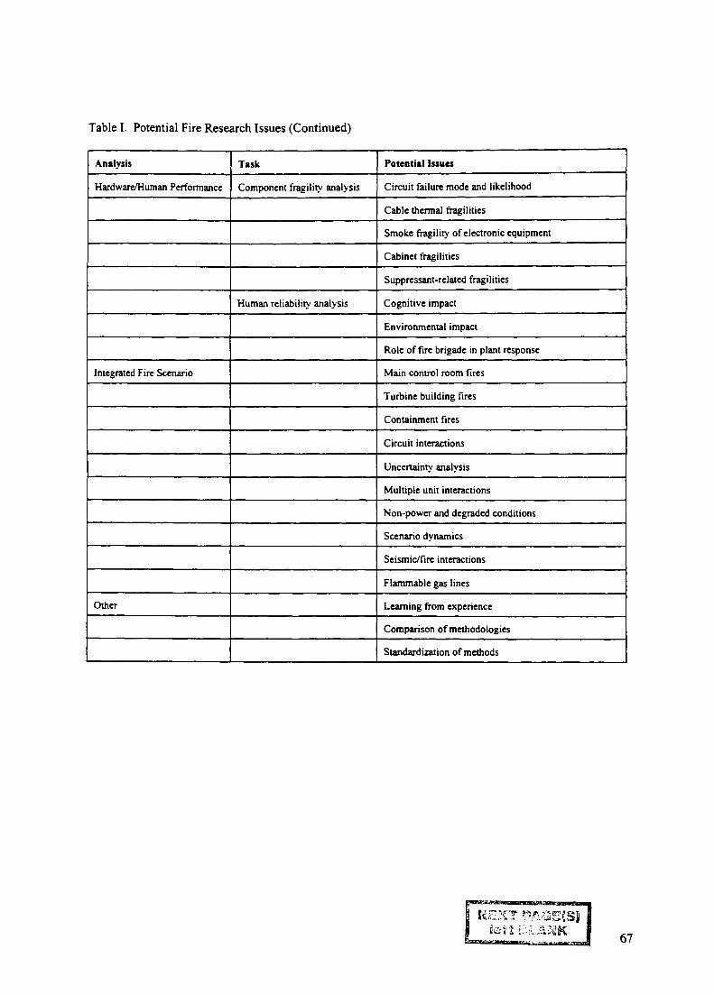
Table I. Potential Fire Research Issues (Continued)
Analysis
Hardware/Human Performance
Integrated Fire Scenario
Other
Task
Component fragility analysis
Human reliability analysis
Potential Issues
Circuit failure mode and likelihood
Cable thermal fragilities
Smoke fragility of electronic equipment
Cabinet fragilities
Suppressant-related fragilities
Cognitive impact
Environmental impact
Role of fire brigade in plant response
Main control room fires
Turbine building fires
Containment fires
Circuit interactions
Uncertainty analysis
Multiple unit interactions
Non-power and degraded conditions
Scenario dynamics
Seismic/fire interactions
Flammable gas lines
Learning from experience
Comparison of methodologies
Standardization of methods
67

IAEA-SM-345/25FIRE PSA METHODOLOGY
M. FUKUDA, T. UCHIDA, T. MUKAE, M. HIRANO XA9847507Institute of Nuclear Safety, Nuclear Power Engineering Corporation,Tokyo,Japan
Abstract
The fire PSA methodology, which NUPEC has introduced from one of US IPEEE fire PSAmethodologies, was applied to a Japanese typical 1,100 Mwe class four loop PWR to confirm theapplicability. Through this application, some consideration is given on some key parameters, such asfire frequencies and severity factor, in the fire PSA methodology to develop the fire PSA modelsspecific to Japanese plants.
1. INTRODUCTION
NUPEC has developed a fire PSA methodology since 1992 sponsored by Ministry of InternationalTrade and Industries. After the introduction of one of US IPEEE fire PSA methodologiesO)>(2) toNUPEC, we have applied the fire PSA methodology at full power operation to seven particular areasof a Japanese typical 1,100 MWe class four loop PWR plant to confirm the applicability of themethodology. This presents the main results of the trial application^) and some consideration on thefire PSA methodology through the application.
2. FIRE PSA METHODOLOGY DEVELOPED IN NUPEC
The fire PSA methodology developed in NUPEC consists of three stages, namely, "spatial interactionanalysis", "screening analysis" and "detailed analysis", as shown in Fig.l. Spatial interaction analysismakes fire scenarios based on plant information. Screening analysis identifies risk significant firescenarios under conservative assumptions. Detailed scenario analysis makes sub-scenarios withoutthe conservative assumptions and quantifies core damage frequencies for the sub-scenarios.
3. MAIN RESULTS OF TRIAL APPLICATION OF THE METHODOLOGY TO A JAPANESEPWR PLANT
In order to confirm the applicability of the methodology to the Japanese LWR plants, to developJapanese specific fire PSA models and to investigate the way to reflect Japanese specificcircumstances to the methodology, we applied the fire PSA methodology at full power operation toseven particular areas of a Japanese typical 1,100 MWe class four loop PWR plant, namely, a turbinebuilding, a main transformer area, a switch-gear room for safety components, a diesel generatorcontrol room, a battery charging room, a component cooling water system (CCWS) pump area and areactor cooling pump (RCP) area. The PWR studied is a 1,100 MWe class four loop type with a largedry pre-stressed concrete containment vessel (PCCV), which has, as the engineered safety features,high pressure injection systems(HPIS), low pressure injection systems (LPIS), containment spraysystems, four accumulators and auxiliary feedwater system s(AFWS). The AFWS composes of threetrains including two motor-driven pumps and one turbine-driven pump.
3.1. Spatial interaction analysis
First, fire areas are defined as the areas surrounded by 2- or 3-hour rated fire barriers, and fire zonesare defined by subdividing fire area. In this study, however, we defined fire scenarios for each firearea without subdividing fire area into fire zones for lack of plant information and fourteen local
69
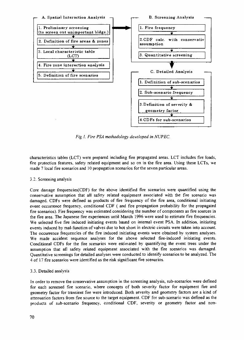
I— A. Spatial Interaction Analysis —•
1. Preliminary screening(to screen out unimportant bldgs.)
2. Definition of fire areas & zones
3. Local characteristic table(LCT)
4. Fire zone interaction analysis
5. Definition of fire scenarios
I B. Screening Analysis ,
1. Fire frequency
2.CDF calc. with conservativassumption
3. Quantitative screening
C. Detailed Analysis
1. Definition of sub-scenarios
2. Sub-scenario frequency
3.Definition of severity &
geometry factor
4.CDFs for sub-scenarios
Fig. 1. Fire PSA methodology developed in NUPEC.
characteristics tables (LCT) were prepared including fire propagated areas. LCT includes fire loads,fire protection features, safety related equipment and so on in the fire area. Using these LCTs, wemade 7 local fire scenarios and 10 propagation scenarios for the seven particular areas.
3.2. Screening analysis
Core damage frequencies(CDF) for the above identified fire scenarios were quantified using theconservative assumption that all safety related equipment associated with the fire scenario wasdamaged. CDFs were defined as products of fire frequency of the fire area, conditional initiatingevent occurrence frequency, conditional CDF ( and fire propagation probability for the propagatedfire scenarios). Fire frequency was estimated considering the number of components as fire sources inthe fire area. The Japanese fire experiences until March 1996 were used to estimate fire frequencies.We selected five fire induced initiating events based on internal event PSA. In addition, initiatingevents induced by mal-function of valves due to hot short in electric circuits were taken into account.The occurrence frequencies of the fire induced initiating events were obtained by system analyses.We made accident sequence analyses for the above selected fire-induced initiating events.Conditional CDFs for the fire scenarios were estimated by quantifying the event trees under theassumption that all safety related equipment associated with the fire scenarios was damaged.Quantitative screenings for detailed analyses were conducted to identify scenarios to be analyzed. The4 of 17 fire scenarios were identified as the risk significant fire scenarios.
3.3. Detailed analysis
In order to remove the conservative assumption in the screening analysis, sub-scenarios were definedfor each screened fire scenario, where concepts of both severity factor for equipment fire andgeometry factor for transient fire were introduced. Both severity and geometry factors are a kind ofattenuation factors from fire source to the target equipment. CDF for sub-scenario was defined as theproducts of sub-scenario frequency, conditional CDF, severity or geometry factor and non-
70

Sub-scenario Frequency (/ry)
1 £-03
1 £-04
1.E-05
1 £-06< GO o O 3 : — • < • < (D CJ CO • < CD
8 8 S 8 8 8 m co CQ S g
Sub—scenario freq. (Factors were taken into account)1.E-03
1 £-04
1 £-05
1 £-06
1.E-07
> t i i i i t I I i I i i i i t I r i i i
I I 1 I I I I I 1 1 1 I t I I I I 1 1 I I
8 8 8 8 8 8 8 8 8 8 8 8 8 £ ™ £ £ * 8 8 § S
1.0E-07
1 .OE-08
1.0E-09
1.0E-10
1.0E-11
1.0E-12
1.0E-13
1.0E-14
CDFs for Sub-scenario (/ry)
1
1
CD
1
O O UJ U-
1 1 1
1 1 1
1 1 1 1
1 ' ' A
CD
I
1
1I-C
o1
•c cs1 1 I
1
1
t
1
2-1
to
1
2-1
i t
i
I I I I I I I I I
8 8 8 8 8 8 8 8 8 8 8
Fig. 2. CDF for sub-scenarios.
71
suppression factor. In principal sub-scenarios are defined for each individual fire source. In this study,however, sub-scenarios were not always made for every individual fire source, but some fire sourcesof which impacts were the same were grouped into one sub-scenario. We made 21 sub-scenarios in allfor 4 screened scenarios. Sub-scenario frequencies were defined as the sum of the fire frequencies offire sources grouped within the sub-scenario. Conditional CDFs for the sub-scenarios were estimatedin the same manner as that for the screening analysis. Unavailabilities of front line systems wereevaluated, reflecting that only safety related equipment associated with the sub-scenarios wasdamaged. Severity factor was applied to sub-scenarios due to equipment ignited fires, which wasdetermined as functions of the distance between the fire source and the target equipment^).Geometry factor was applied to sub-scenarios of transient fuel ignited fires which was defined as afunction of length of target cable tray, critical radius of transient fuel and area of fire zone. Criticalradius were determined by the fire progression analyses with COMPBRN-III e(5). The nonsuppression factors(^) were determined based on the time margin for fire suppression analyzed byCOMPBRM-IIIe considering the fire protection environment in the sub-scenarios. Fig. 2 presents firefrequencies and CDF for the sub-scenarios. Although this study was a limited fire PSA for sevenparticular areas, CDFs for fire sub-scenarios were estimated relatively small with the maximum of10~8/ry. This is mainly because fire occurrence frequency is quite small in Japan and the plant studiedhas safety systems with highly developed physical train separation.
4. CONSIDERATION
Through this study, we could accumulate the experiences of the application of the fire PSAmethodology to the Japanese plant and could confirm the applicability of the methodology itself.However, some key parameters such as severity factors and non suppression factors were derived notfrom Japanese operating experiences but from US data. This chapter gives some consideration onthese parameters based on Japanese specific circumstances, referring to our future work.
4.1. Fire frequencies
Fire frequency for the scenario was estimated considering the number of components as fire sourcesin the fire area. In this study Japanese fire experiences until March 1996 were used to estimateJapanese generic fire frequencies based on the Baysian update technique where the US fireexperiences until 1992(7) w a s usecj a s p r jo r distributions. We identified five fire events from ourevent databases which were applicable to the assessed plant under full operating condition. Thesewere two generator fires, two cable fires and one HVAC fire. Table 1 denotes Japanese generic firefrequency every fire source in comparison with US one. The fire frequencies of fire sources, whichhad no experience in Japan, were estimated to be 10"^10"^/ry depending on the prior distributionthrough the Baysian update. On the other hand Japanese nuclear power plants have been designed andconstructed according to the Japanese fire protection code, where flame-resisting or noncombustiblematerials have been used for cables and other components in the safety system. For example, switch-gears within a reactor building should be oil-less ones, and the quantity of lubricating oil in a pumpshould be minimized during power operation. So that JEAG4607(8)( Fire protection guideline fornuclear power plant prepared in industries side) assumes, as fire hazard sources, pumps withcomparatively large quantity of lubricating oil such as RCP, charging pump and turbine-driven pump,and power cable and so forth. As a result, motor-driven AFW pump, motor-driven valve and control& instrumentation cables are excluded from the fire hazard sources in fire safety evaluation. In orderto reflect these Japanese specific circumstances and to get more realistic fire frequencies in fire PSA,some consideration such as more detailed categorization for fire sources should be made in the future.
4.2. Fire induced initiating events
We selected five fire induced initiating events based on those of internal event PSA(^), namely loss ofPCS(Power conversion system), other transients, loss of CCWS, loss of offsite power and manualtrip. In addition, initiating events induced by mal-function of valves due to hot short in electric
72

TABLE 1. FIRE FREQUENCIES OF COMPONENT TYPES
Fire source
BatteryBattery chargerControl roomDiesel generatorGeneratorHuman errorHVACLogic cabinetMCCMotorCablePumpSwitchgearTransformer(<4kV)Transformer(>4kV)Turbine
Prior distribution (US data)No. of fire
events333
601322
528U5
2130235
2914
Fire freq.(/ry)
2.6E-33.4E-33.4E-35.9E-21.6E-22.4E-24.8E-32.9E-21.2E-24.4E-32.3E-22.4E-22.3E-25.6E-32.8E-22.0E-2
EF
1530161421191519171624
615138
20
Posterior distributionNo. of fire
events0000201000200000
Fire freq.(/ry)
6.1E-44.4E-46.8E-41.6E-33.1E-31.1E-31.7E-31.2E-38.9E-47.2E-43.3E-323E-31.2E-39.0E-41.5E-39.9E-4
EF
91195374578346759
1.2
on
Low-Voltage Equipment (<480V)High-Voltage Equipment (>480V)Mechanical Equipment
8 10Fire Radius (m)
Docket Nos. 50-498 and 50-499. dated January 21,1992.
Fig. 3. Severity factor.
circuits were taken into account. These were PORV(power operated relief valve) LOCA,IS(interfacing system) LOCA and failure of reclose of MSRV(main steam relief valve). Theconditional occurrence frequencies of the above fire induced initiating events were obtained bysystem analyses using fault trees. In principle conditional fire-induced initiating event occurrencefrequencies were given 1.0 except for fire-induced initiating events due to hot short. The probabilityof 0.1 was allotted for hot short in case of a switchgear fire by engineering judgment. This probabilityshould be confirmed theoretically or experimentally considering its control circuit structure(EWD:Elementary Wiring Diagram).
73
4.3. Propagation scenario
In this trial application CDFs of fire propagation scenarios were estimated comparatively large (inFig. 2). This is mainly because of large failure probabilities of fire barrier and coarse fire scenarios.For the fire propagation scenarios, fire propagation probabilities were assessed based on fire severityand fire barrier rating. The failure probability of 2 hour rating fire barrier was assumed to be 0.5 forfire severity of 2 hours, which seems too conservative. Further in this study fire scenarios for fire areawere defined without subdividing fire area into fire zones, which seems too coarse for propagationscenarios as well as local scenarios. We are now re-evaluating fire scenarios with fire area beingsubdivided into fire zones.
4.4. Definition of scenario and sub-scenario
In this application fire scenarios were defined only for safety systems because of lack of plantinformation. However as the fire protection guideline is not always applied to non-safety classcomponents and cables, we must take into account fire scenarios induced by these non-safetycomponents and cables in the future.
4.5. Severity factor
The severity factors represent the probabilities that equipment ignited fires can affect the targetequipment. In this study the severity factors, which are shown in Fig. 3, were derived from US dataand determined as functions of the distance between the fire source and the target equipment^). Thisfigure shows that a mechanical equipment fire affects target components with the probability of 0.3 at1 m from the fire source regardless of its oil possession. Regarding cables, JEAG 4607 asks cables forsafety systems to satisfy the IEEE-383 incombustible standard and the IEEE-384 separation standard,where the distance of more than 90 cm is required between cables. However, Fig. 3 shows thatelectrical equipment has the probability of 0.7 to affect the targets at 90 cm from the fire source. Itsuggests that the severity factor seems too conservative, at least for safety-graded cables. In order toreflect the above Japanese circumstances, severity factor should be more sophisticated withappropriate categorization distinguishing safety graded cables from non-safety graded cables based onsome cable fire experiments and analyses.
4.6. Geometry factor
Geometry factors are applied to sub-scenarios of transient fuel ignited fires ( due to human errors) andare defined as follows;Rg=2rL/Swhere Rg= geometry factor, L= length of target cable tray, r = critical radius of transient fuel, S =area of fire zone or areaCritical radius r were determined by the fire progression analyses with COMPBRN-III e(5) assuming10 gallons transient fuel for each sub-scenario. The quantity and the entrance frequency of thetransient fuel brought in the fire area were estimated based on US data. However, these are quiteinfluenced by the way of plant operation so that these should be based on realistic plant operation.
4.7. Non suppression factor
Fires may not affect target equipment if they are suppressed until target equipment are damaged. Nonsuppression factor represents the failure probability of fire suppression before the targets aredamaged. The non suppression factors were determined based on the reference (6), where the timemargins for fire suppression were analyzed by COMPBRM-IIIe considering the fire protectionenvironment in the sub-scenarios. Non suppression factors were applied to only transient fires in thisstudy. The values of key parameters in these calculations, however, were derived from Surry firePSA(10) SO that the applicability of this model should be confirmed based on some fire experimentsand analyses in the future.
74

5. CONCLUSION
Through this study, we could accumulate the experiences of the application of the fire PSAmethodology to the Japanese plant and could confirm the applicability itself. In order to make the firePSA methodology more conformable to the Japanese plants, we are now applying this methodologyto the remaining areas such as a main control room, where fires in control panels and logic cabinet areanalyzed, together with improving some inconveniences in the methodology found in this application.
REFERENCES
(l)PLG Inc., South Texas Electric Station Probabilistic Safety Assessment, PLG-0675(May 1989)(2)T. Uchida etc. "Development of Fire PSA Methodology atNUPEC", PSA'96, Oct. 1996(3)M.Fukuda etc. "Development of Fire PSA Methodology atNUPEC", Post-SMIRT, August, 1997(4)Docket Nos. 50-498 and 50-499, dated January 21, 1992(5)V. Ho et. al., COMPBRN HIE: An Interactive Computer Code for Fire Risk Analysis, ANGELES,EPRI-NP-7282(May 1991)(6)N.Siu et. al., A Methodology for Analyzing the Detection and Suppression of Fires in NuclearPower Plants, Nuclear Science and Technology, 94,213-226, November 1986(7)PLG Inc., DATABASE FOR PROBABILISTIC RISK ASSESSMENT OF LIGHT WATERNUCLEAR POWER PLANTS Fire Data, PLG-0500, Volume 8(8)JEAG-4607, Japan Electric Association, "Fire Protection Guideline for Nuclear Power Station" (inJapanese), 1986(9)M. Hirano et al, "Recent Activities of Level-1 PSA on Japanese LWR at /NUPEC, PSA'93, Jan.1993(10)Z. Musiki et. al. Evaluation of Potential Severe Accidents During Low Power and ShutdownOperations at Surry Unit 1 Analysis of Core Damage Frequency from Internal Fires During Mid-LoopOperations, BNL NUREG/CR-6144 Vol.13
75
IAEA-SM-345/35Invited Paper
THE FRENCH FIRE PROTECTION CONCEPT. XA9847508VULNERABILITY ANALYSIS
M. KAERCHERBasic Design Department,Electricite de France,Villeurbanne, France
Abstract
The French fire protection concept is based on a principle of three levels of defence in depth :fire prevention, fire containing and fire controlling. Fire prevention is based on arrangementswhich prevent the fire from starting or which make difficult for the fire to start. Fire containingis based on design measures so that the fire will have no impact on the safety of the installation.For fire controlling, equipment and personnel are on duty in order to detect, to fight and to gaincontrol over the fire as early as possible.
The French fire protection concept gives priority to fire containing based on passive structuralmeasures. All buildings containing safety equipment are divided into fire compartments (or fireareas) and fire cells (or fire zones). Basically, a compartment houses safety equipmentbelonging to one division (or train) so that the other division is always available to reach theplant safe shut down or to mitigate an accident.
Because there is a large number of fire compartments and fire cells, deviations from the generalprinciple can be observed. For this reason the RCC-I (Design and Construction Rulesapplicable for fire protection) requires to implement an assessment of the principle of division.This assessment is called vulnerability analysis.
The vulnerability analysis is usually performed at the end of the project, before erection. It isalso possible to perform a vulnerability analysis in an operating nuclear power plant in thescope of a fire safety upgrading programme.
In the vulnerability analysis, the functional failure of all the equipment (except for thoseprotected by a qualified fire barrier, designed or able to withstand the fire consequences) withinthe fire compartment or cell, where the fire breaks out, is postulated. The potentialconsequences for the plant safety are analysed.
These consequences are mainly loss of both divisions of safety function by common modefailure. Some of them can cause a core meltdown. In vulnerability analysis, these consequencesare classified according to 4 criteria :
- common mode failure concerning redundant components of the same safety function,
- Common mode failure concerning support systems of redundant components of the samesafety function,
- Selectivity failure,
- Failure of mitigation systems in case of accidental transient phase caused by the fire.
These potential failures are then assess from the safety point of view, by a functional analysis.If these failures have an impact on the means to reach the safe shut down or to mitigate anaccidental phase, the potential common mode failure is confirmed and must be treatedindividually, mainly by wrapping cables with insulation fibbers.
77

A vulnerability analysis is being implemented on all the French operating plants.
Computerised cable data files are required to select the common mode failures. Functional andfire risk analyses are performed, on a case by case basis, to justify the common mode failures asthey are or to provide modifications for the others. An overview of the first results of thevulnerability analysis is given including a typical description of the modifications proposed toimprove safety at optimal cost.
INTRODUCTION
This document recalls the main stages of the fire protection concept applied by EDF and thenstresses one major point of the French fire protection doctrine: the vulnerability analysis. Thevulnerability analysis mainly involves the identification and treatment of common modefailures and so prevents the fire from destroyed both trains of redundant safety systemsnecessary to reach the safe shut down or to mitigation accidental situations. The practical aspectof this methodology is then explained. The vulnerability analysis is carried out on new projectsbut also for upgrading operating plants. An overview of the first results of the studies andexamples are given.
1. MAIN OBJECTIVES FOR FIRE PROTECTION
Fire protection aims to fulfil three objectives :
- to ensure the safety of personnel,
- to guarantee the availability of the safety systems which are used to shut down the reactor,to maintain long-term subcriticality, to remove the residual heat and to retain radioactivity,
- to limit damage to equipment which could result in long-term unavailability.
The vulnerability analysis brings a significant contribution to the second objective concerningsafety systems.
2. FRENCH FIRE PROTECTION CONCEPT
The French fire protection concept is entirely deterministic. It is based on the following twohypotheses :
- a fire may break out anywhere but only one fire at a time,
- the fire may break out whatever the normal operating status of the plant, under power orduring shut down, or in a post-accident situation.
The fire protection concept is based on a three level defence-in-depth concept: fire prevention,fire containing and fire controlling.
FIRE PREVENTION
Fire prevention is based on arrangements which prevent the fire from starting or which make itdifficult for the fire to start. In concrete terms, this means choosing uninflammable or hardlyinflammable equipment and fluids. Ignition sources have to be controlled.
78
FIRE CONTAINING
If, as a result of human error or of equipment failure, a fire should break out, design measuresare taken so that the fire, whatever the effectiveness of the fire-fighting facilities, will have noimpact on the safety of the installation. The subdivision of buildings into fir compartments andfire cells and the fire barriers set up must therefore confine the fire so that the two redundanttrains of a safety system cannot be simultaneously endangered by the fire
FIRE CONTROLLING
If a fire breaks out, the fire barriers confine it to the fire compartment concerned, thuspreventing any direct impact on plant safety. It is nevertheless necessary in order to limit therisks of spreading of the fire and to preserve the availability of the plant, to gain control overthe fire as early as possible with automatic detection and fire-fighting actions.
3. SUBDIVISION OF BUILDINGS
Containing the fire requires a adequate subdivision of the plants into fire compartments and firecells, a proper qualification of all the items used as fire barriers and a maintenance and periodictest programme which ensures the continued operability of the corresponding components.
To meet this objective, it is necessary to use layout rules based on physical or geographicalseparation of components. For plants involving two redundant trains A and B, that means thatbasically a fire compartment or a fire cell contains equipment of train A or equipment of train Bbut never A and B together.
Subdivision of buildings is the key-point of fire protection programme and no vulnerabilityanalysis can be performed in a plant where the subdivision of buildings into fire compartmentsand fire cells has not been properly done, rewieved and finally approved.
4. VULNERABILITY ANALYSIS (REQUIREMENT)
VERIFICATION PROCEDURE
Verifications (studies and on-site visits) are performed on each installation as it is finished. Anysingularity which does not conform to the design arrangements mentioned above is identified.
This analysis must list the calorific loads in each room, assess the fire duration by firecompartment or cell and assess the efficiency of the physical or geographical separation ofredundant trains.
Because there is a large number of fire compartments and fire cells, deviations from the generalprinciple can be observed. For this reason the Design and Construction Rules applicable to fireprotection (RCC-I) requires to implement an assessment of the principle of separation ofredundant trains. This assessment is called vulnerability analysis. The vulnerability analysis iscarried out on new project but also for upgrading operating plants. The vulnerability analysismainly involves the identification and treatment of common mode failures and so prevents thefire from endangering both trains of redundant safety systems necessary to reach the safe shutdown or to mitigate accidental situations.
79
COMMON MODE FAILURE IDENTIFICATION
The vulnerability analysis is carried out in each fire compartment or fire cell. A potentialcommon mode may be identified when a, b, c or d criteria are fulfilled in the same firecompartment or fire cell:
CRITERION a)
Safety mechanical components or electrical connections belonging to two redundant trains ofthe same system performing a safety function,
CRITERIONb)
Safety mechanical components or electrical connections belonging on the one hand, to the trainof a system performing a safety function, and on the other hand, to systems required to operatethe same system of the redundant train,
CRITERION c)
Electrical connections which are supplied by redundant electrical switchboards, and the numberof which is such that the selectivity of the protection of these switchboards is likely to bejeopardised. The criterion c) relating to the non-selectivity of electrical protection is only takeninto account when a fire is able to reach both electrical connections simultaneously (only theelectrical connections present in the same room shall be taken into account).
CRITERIONd)
Components, the failure of which, in the event of a fire, is likely to result in an accident oradditional operating conditions and components required to perform a safety function necessaryfor mitigating this accidental event.
COMMON MODE FAILURE TREATMENT
If a potential common mode is detected, it will be necessary to install one or more qualified fireprotections or to demonstrate the existence of a functional redundancy, non-affected by the fire,able to perform the safety function endangered by the fire.
EXAMPLES OF IDENTIFICATION OF COMMON MODE FAILUREACCORDING TO CRITERIA a. b. c or d
REDUNDANT COMPONENTS OF THE SAME SAFETY FUNCTION (a)
Example: safety pumps of redundant train located in the same room.
SUPPORT SYSTEMS (b)
Example: cooling systems of safety pumps of redundant train located in the same room.
80
SELECTIVITY FAILURES (c)
Example: Five medium voltage (380V) cables are running through the fire cell 81 (900MWseries). They supply a pump, 3 fans and a heating resistance. Each cable is fed by a circuitbreaker. The overall amperage of breakers (380V) is 8950 A. The rate of the breaker of theemergency power supply (6600V) is 8000A. In this case the fire can cause loss of emergencypower supply by selectivity failure.
Assessment: emergency power supply feeds two other safety fans which are not located in thisfire cell. The cables supplying the redundancies of these 2 fans are not running through this firecell.
Conclusion : loss of emergency power supply does not involve any new common failure mode.
MITIGATION SYSTEMS IN CASE OF ACCIDENTAL TRANSIENTPHASE INDUCED BY FIRE (d):
Examples :
- spurious activation of a pressuriser relief valve,
- opening of a main steam line relief valve caused by the effect of the fire on cables ofpressure sensor.
5. VULNERABILITY ANALYSIS (PRACTICAL METHODOLOGY)
The plant has been properly divided into fire compartments and fire cells. It is assumed that thefire will not propagate from one cell or compartment to another. So this vulnerability analysis isperformed inside each compartment or cell and common mode failures are identified inside thecell or the compartment
The vulnerability analysis only deals with equipment and cables necessary to perform safetyfunctions. In practice the vulnerability analysis is performed, at the first stage on all the safety-related equipment and cables.
CABLE DATA FILES
To perform the vulnerability analysis it is necessary to know exactly which pieces of safetyequipment are lost if a fire breaks out in a compartment. For mechanical components it ispossible to do it manually from drawings and on-site visits, but for fire compartments and firecells containing hundreds of cables, computerised cable data files are required.
The files report the following information for each cable :
- cable route: fire compartment or fire cell, race, tray,
- system involved, division, voltage, power,
- reference of the equipment at both ends of the cables.
81
These data files are implemented as follows :
Basically several cable files are available at the Instrumentation and Control EngineeringCompanies which use them for on-site implementation. These files must be updated withmodifications
For old plants, these files do not cover all the safety cables and they must be upgraded byexisting drawings. If no drawings exist, the file must be built by on-site visual observation.Some special tools have been developed to follow the cable route through penetrations or intrays involving a high number of cables by a French Company AINF. These tools allow us tocarry out the work of detection even during full operation of the plant.
The files must be reviewed and approved as follows :
- it must be verified that all the safety cables are registered on the files,
- a test is made on a random selection of cables. A comparison is made between on-sitearrangement and files. The deviations are analysed and classified into several categoriesaccording to safety impact. The rate of deviation must be less than a few per cent.
IDENTIFICATION OF POTENTIAL COMMON MODE FAILURES
By processing data, it is easy to list all the equipment and cables which are running in one firecompartment or fire cell.
This data processing is done for all the fire compartments and fire cells. Basically, acompartment or a cell contains a majority of equipment of one train: A for instance. Theoperator must then focus on equipment of train B which must be carefully and completelylisted.
The potential common mode failures are generated from this list by using criteria a and b withthe conservative assumption that all the equipment and cables (except for those protected by aqualified fire barrier, designed or able to withstand the fire consequences) within the firecompartment or fire cell, are lost.
In addition, through this process, the operator is able to know precisely which safety functionsare lost, or could be lost in case of fire in a given compartment. This is useful for implementingdetailed procedures for operating the plant in case of fire.
COMMON MODE FAILURE PROCESSING AND ASSESSMENT
At the beginning of the use of this methodology a few years ago, the operator picked out theequipment of the train in the minority and systematically protected it by fire-rated wraps. Today there are four steps of study before deciding to protect the common mode failure. The aimof each step is to examine if the common mode failure could be accepted as it is or not, and inthat case to identify cost optimised modifications.
STEP 1: POTENTIAL COMMON MODE FAILURE
Potential common modes which are identified by data file processing are called potentialcommon modes.
82
Example : Fire cell 280 in Nuclear Auxiliary Building :
- 2 fans train A and B in that fire cell,
- cables supplying these 2 redundant fans are running in the fire cell.
STEP 2: CONFIRMED COMMON MODE FAILURE
At this second stage a functional analysis is performed: a potential common mode failure isconfirmed if it causes safety consequences. The loos of safety function must be analysed innormal state and post accident situation of the plant.
Example : Fire cell 280 in Nuclear Auxiliary Building
Step 1
- 2 fans train A and B in that fire cell
- cables supplying these 2 redundant fans are running in the fire cell.
Step 2
These fans are blowing fresh air in 2 rooms housing high pressure safety injection pumps.Failure of these 2 fans causes overheating of the pump room, failure of both pumps andunavailability of the high pressure safety injection system.
This common mode failure has safety impact so a fire risk analysis is performed at the nextstep.
STEP 3: FIRE RISK ANALYSIS
At this step, an assessment of the first assumption: "the functional failure of all the equipment(excepted those protected by a qualified fire barrier, designed or able to withstand the fireconsequences) within the fire compartment or cell where the fire breaks out is postulated" isdone. The mechanism of fire propagation is analysed considering the possibility of
- Flash over,
- Local fire (cables or equipment),
- Plume or heat radiation,
- Mutual aggression of components.
At this step, it could be decided to implement complementary fire protection measures(sprinklers, screen) to avoid the fire to endanger both trains.
Example : Fire cell 280 in Nuclear Auxiliary Building
Step 1
- 2 fans train A and B in that fire cell,
- cables supplying these 2 redundant fans are running in the fire cell.
83
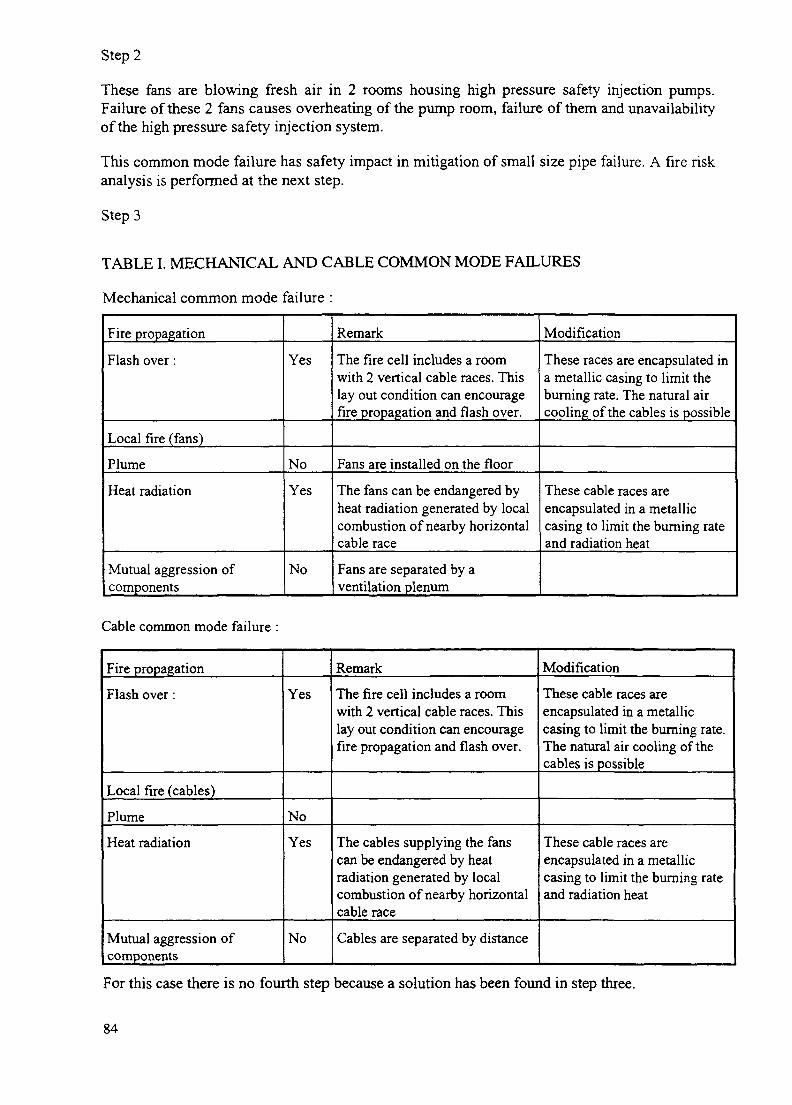
Step 2
These fans are blowing fresh air in 2 rooms housing high pressure safety injection pumps.Failure of these 2 fans causes overheating of the pump room, failure of them and unavailabilityof the high pressure safety injection system.
This common mode failure has safety impact in mitigation of small size pipe failure. A fire riskanalysis is performed at the next step.
Step 3
TABLE I. MECHANICAL AND CABLE COMMON MODE FAILURES
Mechanical common mode failure :
Fire propagation
Flash over:
Local fire (fans)
Plume
Heat radiation
Mutual aggression ofcomponents
Yes
No
Yes
No
Remark
The fire cell includes a roomwith 2 vertical cable races. Thislay out condition can encouragefirejyopagation and flash over.
Fans are installed on the floor
The fans can be endangered byheat radiation generated by localcombustion of nearby horizontalcable race
Fans are separated by aventilation plenum
Modification
These races are encapsulated ina metallic casing to limit theburning rate. The natural aircooling of the cables is possible
These cable races areencapsulated in a metalliccasing to limit the burning rateand radiation heat
Cable common mode failure :
Fire propagation
Flash over:
Local fire (cables)
Plume
Heat radiation
Mutual aggression ofcomponents
Yes
No
Yes
No
Remark
The fire cell includes a roomwith 2 vertical cable races. Thislay out condition can encouragefire propagation and flash over.
The cables supplying the fanscan be endangered by heatradiation generated by localcombustion of nearby horizontalcable race
Cables are separated by distance
Modification
These cable races areencapsulated in a metalliccasing to limit the burning rate.The natural air cooling of thecables is possible
These cable races areencapsulated in a metalliccasing to limit the burning rateand radiation heat
For this case there is no fourth step because a solution has been found in step three.
84

STEP 4: DETAILED FUNCTIONAL ANALYSIS
Step 2 has confirmed that a safety function has been lost. The functional analysis performed atthis step is a detailed functional analysis whose aim is to find whether an other safety systemcan perform the lost safety function.
TREATMENT FOR COMMON MODE FAILURES
The Treatment for common mode failures requires high technology equipment. The mostfrequently adopted solution is to wrap the cables with insulation fibbers.
EDF specifications have been written up for component testing. For cable wraps, fire tests inlaboratories take into consideration the energy dissipated in the cable by the Joule effect, thisenergy being provided by an electrical resistance installed in the neighbourhood of the cableinside the wraps. Tests for assessing the long term behaviour and ageing are also required.
Most of plants use a soft wrap of mineral fibbers designed by the French Company Mecatiss.This equipment is easy to install in all the configuration met in operating plants. The rating isavailable in the range 30 to 180 minutes and is chosen according to the design fire duration ofthe compartment or cell.
6. OVERVIEW OF VULNERABILITY ANALYSIS IMPLEMENTATION
RULES
For French nuclear power plants under construction (N4 series), the design rules concerningfire protection have been issued by EDF, approved by the Safety Authority and implementedsince the beginning of the design.
These rules are formalised in the Design and Construction Rules applicable to fire protection(RCC-I). For N4 series, the vulnerability analysis has been carried out at the design phase.
For operating plants (Fessenheim, Bugey and the series CP1, CP2, P4, P'4), the original fireprotection had been designed in accordance with less complete rules.
The first revision of RCC-I, issued in 1983, only mentioned criterion a. Criteria b and c havebeen introduced in revision 2 issued in 1987. Criterion d was introduced in revision 3 issuedin 1992.
An upgrading programme is in progress in all the operating plants to include most of therequirements of the RCC-I issued in 1992. The set of rules concerning fire protection whichtakes these developments into consideration is formalised in the Fire Directives applicable toeach plant or series.
IMPLEMENTATION: FIRST RESULTS
The first results (see appendix for details) show that:
55% of the common mode failures are accepted as they are,
32% are treated with wraps,
5% are treated with different solution,
8% are still in process.
85

7. CONCLUSION
Protection against the risk of fire is based on requirements involving three levels of defence indepth.
To ensure that the design hypotheses are fulfilled, a verification phase including a vulnerabilityanalysis is performed at the end of the project.
The vulnerability analysis assumes a conservative assumption that all the equipment and cables(excepted those protected by a qualified fire barrier, designed or able to withstand the fireconsequences) within the fire compartment are unavailable and identifies the common failuremode.
Computerised cable files are required to perform this task. This methodology requires asignificant contribution of functional and fire risk analysises and allows us relevant costreduction on series.
The vulnerability analysis increases the operator's confidence for the efficiency of thecompartmentation.
In case of fire this methodology guarantees the availability of the safety functions and providesinformation about availability of safety systems to plant operators.
86

Appendix
COMMON MODE FAILURE (CMF)
FUEL BUILDING
PotentialCMF22
ConfirmedCMF3
AcceptableCMF1
Treatment
2
Cablewrapping2
NUCLEAR AUXILIARY BUILDING
PotentialCMF29
ConfirmedCMF9
AcceptableCMF0
Treatment
9
Cablewrapping4
Metallicwrapping1
Cabinetwrapping3
Sensorwrapping1
REACTOR BUILDING
PotentialCMF
56
ConfirmedCMF
25
AcceptableCMF
later
Treatment
SWITCHGEAR BUILDING
PotentialCMF
235
ConfirmedCMF
117
AcceptableCMF
1
Treatment
116
Wraps
102
Cablererouting
9
Screen
5
87

IAEA-SM-345/2PILOT FIRE RADIUS SIZE AND ITS VARIATIONREGARDING THE UNCERTAINTY IN FIRE RISK ASSESSMENT
J. ARGIROVBulgarian Academy of Sciences, XA9847509Institute for Nuclear Research and Nuclear Energy,Sofia, Bulgaria
Abstract
The impact of a combustible load with limited amount of heat on the characteristics of firegenerated local environment is considered. The combustible load apportionment on the floor and itsability to release the heat at a different rate regarding the temperatures and heat flux in zones formedin the NPP compartments is studied using calculations. Several ways of variation of a pilot fire radiusin the same range are compared.
1. Introduction
To evaluate more realistically the damages that might occur in the critical fire scenariosspecified for NPP compartments the deterministic physical models are usually usedsimultaneously with probabilistic methods. A commonly used tool in the field of fire PRA isthe computer code COMPBRN the last version of which is described in reference [1].According to reference [2] about 15 parameters are significant among the numerous onesdetermining the influence of a fire generated local environment on a vulnerable component.These parameters can be divided in several groups. The first group includes parameters suchas dimensions of compartment whose members can be considered as constants for all firescenarios taking place in a given NPP compartment. The second group includes parameterswith large states of knowledge uncertainties, such thermo-physical properties of materials,burning efficiency, damage temperature and so on, that are represented by distributions ratherthan by point values. The last group includes parameters, such as the radius of the pilot fireand burning rate of combustibles involved in a flame, that are very significant regarding theway a fire grows. The values of these two parameters are closely related to the temperatures offlame, plume and hot gas layer (HGL) as well as the depth of HGL, released heat flux, etc.The temperatures of separate zones of a fire generated environment and the released heat fluxstrongly determine the damages due to a specific fire scenario.
Reference [3] shows that between the size of the burning pool and the current value ofpyrolysis rate a strong (physical) relation exists. From this point of view the impact of the firescenarios taking place because of a flammable material of a known type and quantity on thesize of the pool and on the pyrolysis rate can be easily evaluated. It is not a common case inNPP compartments where many objects with unknown combustible loads and burning ratesare located. To assess the impact of the fire scenarios the radius of a pilot fire is usuallyassumed according to a hypothesis for fire of the size that is expected. Once the total amountof heat expected to be released at combustion and the fire size are specified the degree ofexpected fire severity can be represented using different types of a flammable material.
In the case of a pool fire the quantity of flammable material involved in combustion willdetermine the value of its radius. The variation of the pool radius during the fire growth canbe evaluated approximately. A possible way is the current quantity of specified flammablematerial to be 'put' in a volume between a simple 'top surface', for instance part of a sphere,
89

and 'bottom surface' such as the floor. To model the flame size and its likely variation duringthe combustion of an object with unknown burning rate the constant, increasing anddecreasing radius of a pilot fire can be used. In case the bound values for a pilot fire radiuscorresponding to the specific fire scenario are defined it is important to know how to describethe values of the radius inside the range. The random variation of the radius in acorresponding range, as for parameters of the second group, or variation based on physicalrelations is possible to be applied.
2. Description of the scope
To trace how the choice of a pilot fire radius and burning rate of combustiblesinfluences the time to damage of a 'normal' cable one specific situation is studied to avoidabstract reasoning. Compartments of medium size, X = 10 m, Y = 5 ra and Z = 4 m, areconsidered. A flammable object with total combustible load only of about 450 MJ andunknown burning rate is assumed to generate this heat in a compartment. The total amount ofheat that will be released during combustion is approximated by a corresponding quantity ofdifferent types of flammable liquids. According to ref. 3 the net heat of combustion for crudeoil is 42.7 MJ/kg and for heptane is 44.6 MJ/kg. From this point of view the combustible loadmay be represented by equivalent of either 10.1 kg of heptane or 10.5 kg of crude oil. It isvery important how the equivalent quantity of flammable liquid will be distributed on the'bottom surface' because of the dependency between the pool size and pyrolysis rate. Theburning rate of the flammable object is defined approximately when using the hypothesesabout the expected time for the total heat of combustion to be released. Assuming an expectedtime for release of the total amount of heat - tr s and a radius of pilot fire - Rf m the averagedvalue of the pyrolysis rate can be evaluated. The averaged mass burning rate mm kg/s andpyrolysis rate ms kg/m s are obtained by simple relations (1) and (2). Equation (3)recommended in ref. [2] is also used.
mm = amount of equivalent flammable liquid / expected time for release of heat (1)
ms = mm/S (2); S = 7t»Rf2; ms = 1^(1 - exp(-2*R,*k)) (3)
The constants k and m, for the corresponding equivalent flammable liquid are obtainedin ref. [3].
Table I shows the distributions and ranges used to describe the state of knowledgeuncertainty about parameters of the 'second group'.
3. Choice of pilot fire radius and type of equivalent flammable liquid.
The hypothesis for pilot fire with a constant radius during combustion is consideredfirst.
The hypotheses about the expected time for the total heat of combustion to be releasedare used to define approximately the radius. It is assumed that the combustible load is releasedfor more than 720 s with mass burning rate equivalent to the pilot fire of a crude oil pool. Theconstants k - 2.8 1/m and m, = 0.045 kg/m2s for crude oil are obtained from the ref. [3]. Theaveraged value of mass burning rate of 10.5/720 can be obtained by means of relation (1).Using relations (2) and (3) the value of pilot fire radius Rf < 0.35 m can be estimated. Thevalues of HGL temperature and depth as well as the time to failure of a cable are calculatedusing an improved version of the programs reported in ref. [4]. The programs use the responsesurface approximations for these entities presented in ref. [2]. Distributions of any one of theparameters shown in table 1 are described by means of 200 point values generated using Latinhypercube sampling. In the case of crude oil pilot fire with radius Rf = 0.35 m, having a
90

pyrolysis rate ms = 0.0387 kg/m^s, all 200 calculated values for HGL temperature fall in therange of 385-490 K. The above mentioned programs are used to calculate the time to damageof a 'normal' cable. Distributions used to describe the state of knowledge uncertainties aboutdamage temperature and thermo-physical properties of a 'normal' cable are shown in a table I.A cable tray with a depth of 0.076 m, immersed in the HGL and placed at a distance 3 m fromthe flame is considered. The calculations show that a heat flux on the cable surface for adistance of 3 [m] between the flame and the cable is in the range of 3.6 - 4.0 kW. In this casethe damage temperature will be reached only in 4 of 200 trails.
Let us now assume a pilot fire with the same radius that releases the same total amountof heat (450 MJ) but at the burning rate of heptane. For heptane the values of constants k = 1.1and ntj = 0.101 are applied. Using equation (3) the pyrolysis rate of ms = 0.0542 kg/m2s iscalculated. The time xr = 484 s is obtained using the relations (1) and (2). The calculatedvalues of the HGL temperature and the heat flux on the cable surface fall in the ranges
420-580 K and 5.57-6.54 kW if only the pyrolysis rate is changed in the input data. Thenumber of trials that show the cable temperature is smaller than the damage one are 34 in thiscase. The number of tirals showing no damage are 52 if the same values for the heat flux onthe cable surface, as calculated for oil pilot fire, are used. Taking into account the above it canbe seen that if the same pilot fire radius is used the choice of burning rate of the flammableobject is significant to the damages of vulnerable components.
In case the oil pilot fire with radius 0.5 m is considered the HGL temperatures fall in therange 580-630 K. If cable - flame distance is 9 m the heat flux on the cable surface is in therange 260-280 W. When the cable is immersed in HGL, no matter the low value of externalheat flux, the damage temperature is reached in 190 of 200 trials. The calculations show thatin the case of heptane pilot fire with the same radius the HGL temperatures fall in the higherrange of 650-735 K because of its higher severity. The trials without damage are only 3 or thispilot fire will lead definitely to failure of cables involved in a hot gas layer. The values of timexr for two pilot fires corresponding to heptane and crude oil mass burning rates are 316s and190 s. The flammable object, despite its small combustible load, that is able to generate flameradius bigger than 0.5 m or to release the heat faster that 300 s is real a danger for the cables.For flammable objects with limited combustible load the hypothesis of constant pilot fireradius is a very conservative one.
4. Random vs. 'physical' variation of a pilot fire radius
In the above paragraphs an influence of the small combustible load located in a mediumsize compartment regarding the possibility a 'normal' cable to be damaged was studied. Thedistribution of the equal combustible load on a 'bottom surface', represented by means of apilot fire radius, was found to have significant impact on the fire risk. It was shown that if thepilot fire radius is fixed the ability of the flammable object to release faster the heat,represented by the hypothesis of the burning rate, is also an important characteristic. For thecompartment, combustible load and 'normal' cable under study the pilot fire radius of 0.5 mwas obtained to lead to damage of the cables immersed in HGL. The pilot fire radius of 0.35m is a critical one for the situation under consideration. The low severity fire, with which heatis released at the lower oil burning rate, cannot damage the cable if it is located at more than 2m from the flame. Calculations show that with a high severity fire, having the burning rate ofheptane, the damage temperature can be reached if the 'normal' cable is immersed in a HGL.In 82-166 of 200 trials the damage temperature is reached when the distance between flameand cable immersed in HGL varies in the range 9-2 m.
91

TABLE I. CHARACTERISTICS FOR RANDOMLY VARIED PARAMETERS
Randomly varied parameters
Heat of combustion - *EbH f [MJ/kg]
Compartment ceiling thermal conductivity - k] [W/mK]
Cable emissivity - £ [-]
Cable thermal conductivity - kc [W/mK]
Cable thermal diffusity - a [m /s]
Damage temperature of cable - Tfam [K.]
Range (oil)
38.4 - 42.7
0.4- 1.0
0.7-0.95
0.09-0.5
1.8x10 -7.0x10
450 - 500
Range(heptane)
38 - 44.6
0.4- 1.0
0.7-0.95
0.09 - 0.5
1.8x10 -7.0x10
450 - 500
Distribution
normal
normal
uniform
lognormal
uniform
uniform
* The symbol Eh denotes the burning efficiency.
TABLE II: RANGES OF THE CALCULATED ENTITIES IMPORTANT TO THE DAMAGE OF A'NORMAL' CABLE
Ranges of the calculated entities
Pyrolysis rate - ms [kg/m~s]
Heat flux on the cable surface - +q [W/m2]
Width of a hot gas layer - L [m]
Temperature of hot gas layer - T^ [K]
Temperature on a cable surface - T c [K]
Number of trails the damage temperature isreached
Range of a time to damage on condition acable is HGL - xc [s]
HI & H2*2 2
3.61x10" -3.94x10"
5.43x10' -6.73x10"3300-4370
5600 - 8500
2.68-2.75
2.71-2.80
464 - 568525 - 670
340 - 500
342 - 500
116
185
38- 105
24-92
H3&H4
3.79x10"->
6.07x10""3730-4110
6610-7768
2.716
2.748
490 - 535
555 632
346 - 500
360 - 500
139
192
53-80
33- 105
H5&H6
3.81x10""
6.15x10""
3760-44106730 - 7900
2.72
2.75
493 - 545565 640
355 500
379 - 500
148
194
51 -91
32-112
* The symbols HI & H2 denote the hypotheses for random variation of pilot fire radius in cases the oiland heptane are burning. The symbols H3 & H4 are used to denote the hypotheses for decreasing radius and bysymbols H5 & H6 the hypotheses for initially increasing fire radius are marked.
+ The heat flux on the cable surface is calculated for flame - cable distance equal of 3 [m].
In this study the impact of small combustible loads regarding damages of a 'normal'cable is considered. It is likely the flame size to be changed during the fire growth if limitedcombustible load is available. The variation of the pilot fire radius in a specified range can beused to represent the uncertainty in expected time the heat of thr combustible load will bereleased. The time xr is practically impossible to be evaluated by a point value. Using anexpert opinion this time can be estimated within a range. Assuming the pilot fire radius willbe changed during a specific fire scenario the question arises how the hypotheses about theways of variation influence the time to damage of a 'normal' cable. Two main trends in the
92

flame radius change are likely to occur. A flame radius will decrease during combustion if itinvolves at once the whole combustible load. A fire will be grown in a different way if thepart of the same combustible load covered with flames increases until the moment when thewhole combustible load is involved. In such a case the flame radius will increase initially andthen will start to decrease.
Hypotheses for the changes a pilot fire radius in a random variation and the two cases offire growth mentioned above are compared. The bound values of 0.35 and 0.5 for the range ofthe pilot fire radius are used. The random variation of the fire radius is depicted using theuniform distribution and 200 point values generated by means of Latin hypercube sampling.
- Series 1 • Series2 -Series3 -Series4
7.00E-02
6.00E-02JP£ 5.00E-02
"^ 4.00E-02
5
« 3.00E-O2
3 2.00E-O2
a 1 00E-O2
O.OOE+00 4O.OOE+00 5.00E+01 1.00E+02 1.50E+02 2.00E+02 2.50E+02 3.00E+02 3.50E+02
Time (s)
FIG. 1. Variation in the pyrolysis rate versus time per crude oil and heptane(for explanation of symbols, see Table II).
r
1
1s-o-©-o-o-< >-0-©-©-0-Q_o
Series 1 - H3; Series 2 - H5; Series 3 - H4; Series 4 - H6
£
J3
3
50
45
40
35
30
25
20
15
10
5
I
•
1
J3 r
J n.r
r
ft M
FIG.
O.OOE-iOO 2.00E-IO1 4.00E-I01 6.OOE-1OI 8.00E-1O1 1.OOE-IO2 1.2OE-IO2
Time to damage (s)
2. Distribution of the time taken to damage a cable in the HGL (H5 and H6).
93

The cases of 'physical' variations of the pilot fire radius in a specified range are evaluated asoil and heptane equivalents of a combustible load 'burning' in a pool. The heptane equivalentof combustible load is used to represent a hypothesis that a time xr cannot be outside the range190 -480 s when a flammable object generates a high severity fire. In the case of decreasingradius the fire is assumed to start at a pool radius of upper bound ( 0.5 m). The crude oilequivalent is used to study the hypothesis that time tr cannot be outside the range 315 -720 swhen flammable object lead to a low severity fire.
The inside values of the fire radius range and the corresponding pyrolysis rates arecalculated on the basis of the current quantity of flammable liquid equivalent using theprograms reported in ref. 4. The values of the fire radius and of the pyrolysis rate are averagedfor the time interval the radius reaches the lower bound of 0.35 m. For the case of initiallyincreasing pilot fire it is assumed that the flame starts with 20 % of the flammable liquid andfor 30 s involves all the available quantity. Here the values of the fire radius and pyrolysis rateare also integrated over time.
Variations of the pyrolysis rate during the time interval the radii of pilot fires reach thelower bound of 0.35 m for burning of crude oil and heptane equivalents are shown in fig. 1.The flame, plume and HGL temperatures as well as the heat flux on the cable surface arecalculated using the corresponding values of the parameters in all 200 trials. For any of thehypotheses about pilot radius variation the parameteres of the 'second group' are presented asthe same set of 200 point values generated by Latin hypercube sampling is used. The averagedvalues of fire radius and pyrolysis rate are applied in all trials that describe the cases of'physical' variations. The hypothesis for random variation of pilot fire radius in contrast usesa set of 200 point values for fire radius as the corresponding values for pyrolysis rate arecalculated by equation (3). The ranges of calculated values for entities important for thedamage of a cable are shown in table II. The data of table II shows that the hypotheses for'physical' variation of the pilot fire radius in the cases of both low and high severity fires leadto damage of a cable in a graet number of trails.
Distribution of the time to damage of a 'normal' cable assuming the pilot fire radius willinitially increase (hypotheses H5 & H6) is shown in fig. 2. It can be seen that with bothhypotheses the main part of the trails where damage temperature is reached is situated near thelower bound of the time interval.
5. Conclusions
The impact of a limited amount of heat released in a medium size compartment isconsidered. The distribution of material that releases the heat is reflected by pilot fire radius.The ability of a material to release the heat at different rates is described with a type offlammable material that is chosen. The influence that different hypotheses about size andvariation of the pilot fire radius have regarding the possibility a cable to be damaged wastraced. Calculations conducted by means of response surface approximations presented in ref.[2] show the damage of a cable is very sensitive to the choice of a hypothesis.
ACKNOWLEDGEMENT
This research was completely sponsored by IAEA project No 9302/RO and conducted atthe Institute for Nuclear Research and Nuclear Energy, Sofia, Bulgaria.
94
REFERENCES
[1] Vincent, H., Apostolakis, G., Compbrn Hie - a computer code for probabilistic fire riskanalysis, Nuclear Engineering and Design 138 (1992) 357-373
[2] Brandyberry, M., Apostolakis, G., Response Surface Approximation of a Fire RiskAnalysis Computer Code, Reliability Engineering and System Safety 29 (1990) 153-184
[3] Babrauskas, V., Estimating Large Pool Fire Burning Rates, Fire Technology, 19(1983) 153-184
[4] Argirov, J., "Simplified Modelling of Fire Impact from Spot of Flammable Liquid intoCompartment in the Frame of Fire Risk Assessment by Response Surface Methodology",Probabilistic Safety Assessment and Managment'96 (ESEL'96 & PSAM-III Conference),June 24-28, Crete, Greece, Edited by Carlo Cacciabue and Ioannis Papazoglou, Vol. 2 1205-1210
FIRE SAFETY ANALYSIS: APPLICATIONS
(Session 3)
Chairperson
M. KAERCHERFrance
IAEA-SM-34S/1A FIRE HAZARD ANALYSIS AT THEIGNALINA NUCLEAR POWER PLANT
F.JORUD XA9847510
Sydkraft Konsult AB,Malmo
T. MAGNUSSONVattenfall AB,Ringhals, Varobacka
Sweden
Abstract
The fire hazard analysis (FHA) of the Ignalina Nuclear Power Plant (INPP) Unit no.l wasinitiated during 1997 and is estimated to finalise in summer 1998. The reason for starting a FHA wasa recommendation in the Safety Analysis Report and its review to prioritise a systematic FHA. Fireprotection improvements had earlier been based on engineering assessments, but furtherimprovements required a systematic FHA. It is also required by the regulator for licensing of unitno.l. In preparation of the analysis it was decided to perform a deterministic FHA to fulfil therequirements in the IAEA draft of a Safety Practice "Preparation of Fire Hazard Analyses for NuclearPower Plants". As a supporting document the United States Department of Energy Reactor CoreProtection Evaluation Methodology for Fires at RBMK and VVER Nuclear Power Plants (RCPEM)was agreed to be used. The assistance of the project is performed as a bilateral activity betweenSweden and UK. The project management is the responsibility of the INPP. In order to transferknowledge to the INPP project group, training activities are arranged by the western team. Theproject will be documented as a safety case.
The project consists of parties from INPP, Sweden, UK and Russia which makes the projectvery dependent of good communication procedures. The most difficult problems is except from theproblems with translation, the problems with different standards and lack of testing protocols of thefire protection installations and problems to set the right level of screening criteria. There is also thenew dimension of making it possible to take credit for the fire brigade in the safety case, which canbring the project into difficulties. The most interesting challenges for the project are to set the mostsensible safety levels in the screening phase, to handle the huge volume of rooms for survey andscreening, to maintain the good exchange of fire- and nuclear safety information between all theparties involved, to assure a good quality assurance during the project and to handle lack ofinformation when making judgements about the reliability of the fire protection devicesjThe RCPEMis a good help, but the project also demands the involved exr>errt<»» *^ u~ flexible and make good plansto handle the new type of evaluation prob
1. IntroductionIgnalina Nuclear Power Plant is ; one was in commission
1983 and unit two in 1987. Since 1992 provided aid to INPP inorder to increase the safety level. Lot o. to implement the INPPexperts in the projects in order to transl ^ . , , u n auout nuclear safety. Thebenefit from that is for instance an improvement of the overall safety culture at INPP.
In difference to an average western plant the fire brigade is very comprehensive inorder to provide the plant with good fire protection. Instead there are some places where onewould expect to find fixed fire fighting systems or barriers in comparison to a western plant.
99
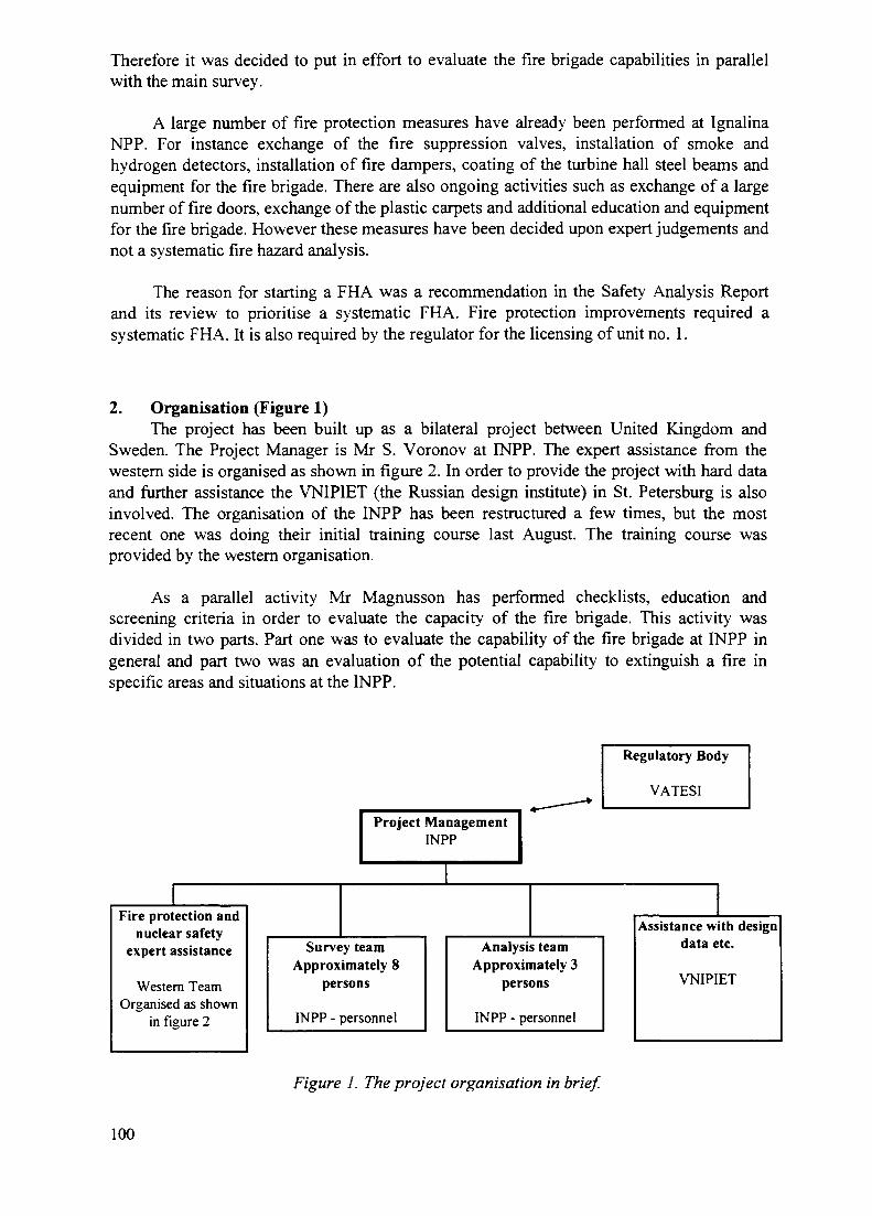
Therefore it was decided to put in effort to evaluate the fire brigade capabilities in parallelwith the main survey.
A large number of fire protection measures have already been performed at IgnalinaNPP. For instance exchange of the fire suppression valves, installation of smoke andhydrogen detectors, installation of fire dampers, coating of the turbine hall steel beams andequipment for the fire brigade. There are also ongoing activities such as exchange of a largenumber of fire doors, exchange of the plastic carpets and additional education and equipmentfor the fire brigade. However these measures have been decided upon expert judgements andnot a systematic fire hazard analysis.
The reason for starting a FHA was a recommendation in the Safety Analysis Reportand its review to prioritise a systematic FHA. Fire protection improvements required asystematic FHA. It is also required by the regulator for the licensing of unit no. 1.
2. Organisation (Figure 1)The project has been built up as a bilateral project between United Kingdom and
Sweden. The Project Manager is Mr S. Voronov at INPP. The expert assistance from thewestern side is organised as shown in figure 2. In order to provide the project with hard dataand further assistance the VNIPIET (the Russian design institute) in St. Petersburg is alsoinvolved. The organisation of the INPP has been restructured a few times, but the mostrecent one was doing their initial training course last August. The training course wasprovided by the western organisation.
As a parallel activity Mr Magnusson has performed checklists, education andscreening criteria in order to evaluate the capacity of the fire brigade. This activity wasdivided in two parts. Part one was to evaluate the capability of the fire brigade at INPP ingeneral and part two was an evaluation of the potential capability to extinguish a fire inspecific areas and situations at the INPP.
Project ManagementINPP
Regulatory Body
VATESI
Fire protection andnuclear safety
expert assistance
Western TeamOrganised as shown
in figure 2
Survey teamApproximately 8
persons
INPP - personnel
Analysis teamApproximately 3
persons
INPP - personnel
Assistance with designdata etc.
VNIPIET
Figure 1. The project organisation in brief.
100
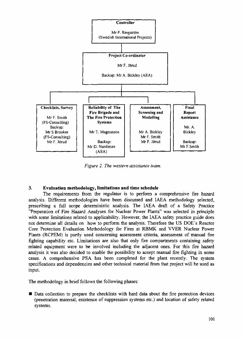
Checklists, Survey
Mr F. Smith(FS-Consulting)
Backup:Mr S Brooker
(FS-Consulting)Mr F. JQrud
Controller
Mr P. Ringstrom(Swedish International Projects)
Project Co-ordinator
Mr F. Jorud
Backup: Mr A. Bickley (AEA)
rReliability of TheFire Brigade and
The Fire ProtectionSystems
Mr T. Magnusson
Backup:Mr D. Hardiman
(AbA)
1Assessment,
Screening andModelling
Mr A. BickleyMr F. SmithMr F. Jorud
FinalReport
Assistance
Mr. A.Bickley
Backup:Mr F.Smith
Figure 2. The western assistance team.
3. Evaluation methodology, limitations and time scheduleThe requirements from the regulator is to perform a comprehensive fire hazard
analysis. Different methodologies have been discussed and IAEA methodology selected,prescribing a full scope deterministic analysis. The IAEA draft of a Safety Practice"Preparation of Fire Hazard Analyses for Nuclear Power Plants" was selected in principlewith some limitations related to applicability. However, the IAEA safety practice guide doesnot determine all details on how to perform the analysis. Therefore the US DOE's ReactorCore Protection Evaluation Methodology for Fires at RBMK and VVER Nuclear PowerPlants (RCPEM) is partly used concerning assessment criteria, assessment of manual firefighting capability etc. Limitations are also that only fire compartments containing safetyrelated equipment were to be involved including the adjacent ones. For this fire hazardanalysis it was also decided to enable the possibility to accept manual fire fighting in somecases. A comprehensive PSA has been completed for the plant recently. The systemspecifications and dependencies and other technical material from that project will be used asinput.
The methodology in brief follows the following phases:
• Data collection to prepare the checklists with hard data about the fire protection devices(penetration material, existence of suppression systems etc.) and location of safety relatedsystems.
101
• Survey, performed as a walk through filling in the checklists for each room involved in theanalysis.
• Screening where the areas/rooms are sorted in - needs further consideration/analysis or thearea/room fulfils the screening criteria.
• Analysis of the areas required further analysis during the screening phase
The scope of the fire hazard analysis is unit one. The building is enormous andconsists of about 700 rooms, but it has been decided to start with 200 rooms. Those roomsare the one containing safety related equipment with the knowledge of today. It is estimatedthat more rooms will have to be surveyed before the criteria of the project is reached.
The original time schedule for the fire hazard analysis was a completion of the final reportbefore the 1st of March 1998. The estimation of today is to finalise in summer 1998.
4. The main survey teamIn order to perform the walk down survey, checklists had to be prepared. There were
checklist forms in the RCPEM but they were not found to be suitable on detailed level. Thenew checklists have the advantage to be partly developed by the survey team and thereforeaccepted and understood. The training started with the western team explaining the meaningof each item in a checklist template. To exemplify the western team filled in the checkliststogether with the INPP personnel in a cable spreading room and a battery room. After thatthe survey teams (three teams led by Mr Voronov, two in each team) had to split up in orderto perform a complete survey of one room each. Rooms in vicinity of each other werechosen in order to enable western assistance with translation.
To enable the initial screening the project decided to follow items (1), (2) and (3) inparagraph 202 of the IAEA Guide 50-SG-D2 These items are dealing with ensuring safe shutdown, removing residual heat and ensuring that any release are below prescribed limits. Alsothe single failure criteria was established as described in paragraph 216 of the IAEA Guide.In practice mutually redundant plant performing the same function should (preliminaryinterpretation, suggested by the western experts) be:
• In different fire compartments segregated by 3 hour barriers or• In different fire zones separated by more than 6 metres horizontally with no intervening
combustibles. Each fire zone should have an automatic fire detection and extinguishingsystem, or
• In different fire sub-compartments separated by fire barriers with a 1 hour rating. Each firesub-compartment should have an automatic fire detection and extinguishing system, or
• In the same fire zone but protected by 2 diverse methods of fire detection and fast-actingfire extinguishing system.
These issues are used in the safety principle for existing UK plants and will perhaps bereconsidered during the project.
The screening criteria in the RCPEM were found to be well adjusted when meeting theproblems in a Russian designed NPP. The criteria the project found out to be well adjustedwere for instance judgements about the doors and penetrations.
102
A number of different technical documents have been produced or are underproduction to facilitate the process of screening and modelling. These documents are forinstance:
• Screening criteria• A template for the final FHA report• Criteria and methods for assessing fire resistance and fire compartment boundary• A guide on the fire resistance of steel and structural fire resistance• A guide for determining generic fire loads for electrical cabinets
The main problem so far has been the lack of data from fire tests of the fire protectiondevices. For instance the cable coating material, dampers, penetration seals etc.
5. Evaluation of the fire brigade capability.The western team started with an evaluation of the fire brigade using the checklist in
the RCPEM. At the same time the team was getting familiar with the fire brigade.
Most of the evaluated subjects were considered as satisfactory. However there weresome subjects that need further consideration. Most of the findings that need furtherevaluation are planned to be upgraded. The main problem in this evaluation is that the firebrigade doesn't have adequate fire fighting equipment available to fight all kinds of fires. Forexample they don't have high expansion foam equipment to use in areas with high voltage.There are also some problems with personal protective equipment.
The team found the checklist and the screening criteria in the RCPEM -checklist, welladjusted to the problems in Russian designed reactors. As soon as the main survey teamnotifies an area in need of the fire brigade extinguishing capability, there will be anadjustment of the proposed screening criteria.
6. Evaluation of the potential capability to extinguish a fireThe training of the survey started with the western team trying to explain the meaning
of each item in the checklist. To exemplify, the western team filled in the checkliststogether with the INPP- personnel for a local relay room. The team consisted of plantpersonnel and personnel from the fire brigade.
The team had to make a special checklist about the capability to extinguish a fire in acertain room. One of the remaining problems is that there are need of judgements to be madeof the local fire brigade, but the head of the fire department is at the same time the inspectionauthority for INPP fire protection compliance. Therefore the fire brigade can only work asinput provider in the project. Screening and analysis competence have to be obtained fromelsewhere. This is an important role for the Western experts.
The screening criteria that are used for this type of room (for instance a local relayroom) which was estimated to be a common type of room in the plant, are as follows:
• Can the plant staff be in the area within 2 minutes?• Can the plant staff control and contain the fire until the fire brigade arrives (the next 4
minutes) ?• Can the fire brigade attend and extinguish a fire in < 6 minutes ?
103
If the screening criteria are not fulfilled the project has to perform further evaluation.The time criteria were based on the fire event to be expected for this type of room. Thejudgements were made by the involved project expertise.
The main problem here is to provide the analysis with realistic data about the firebrigade capability. The western team has for instance notified an attitude from the firebrigade that nothing unexpected could happen on their way to the fire room, such as nobodymeets up and opens the gates to the plant area or somebody has forgotten a tube withwelding gas.
7. ChallengesThe most interesting challenges for the project are:
• to set the most sensible safety levels in the screening phase,• to handle the huge volume of rooms for survey and screening,• to maintain the good exchange of fire- and nuclear safety information between all the
parties involved• to assure a good quality assurance during the project• to handle lack of information when making judgements about the reliability of the fire
protection devices.
The RCPEM is a good help, but the project also demands the involved expertise to beflexible and make good plans to handle the new type of evaluation problems.
104

IAEA-SM-345/9АНАЛИЗ ВЛИЯНИЯ ПОЖАРОВ И ИХ ПОСЛЕДСТВИЙНА БЕЗОПАСНЫЙ ОСТАНОВ ЭНЕРГОБЛОКА СРЕАКТОРОМ ВВЭР-1000
Г СОЛДАТОВ ХА9847511
Всероссийский институт по эксплуатацииатомных электростанций
В. МОРОЗОВ, Е ТОКМАЧЕВИнститут Атомэнергоггроект
Москва, Российская Федерация
Abstract- Аннотация
ANALYSIS OF THE EFFECT OF FIRES AND THEIR CONSEQUENCES FORTHE SAFE SHUTDOWN OF A UNIT WITH A WWER-1000 REACTOR.
This paper describes the status of work, and the results obtained, on the problem of safeshutdown of a nuclear power plant with a WWER-1000 reactor (V-320) in the event of a fire.The study focused on Unit 4 of the Balakovo nuclear power plant, which has been in operationsince December 1993; it started in 1996 and should be complete by December 1997.
The methodology used for the analysis includes a deterministic approach to the analysisof safe shotdown, incorporating probabilistic safety assessment techniques.
The study is based on the results of a probabilistic safety assessment, an analysis of the spa-tial distribution of equipment posing a fire risk and of fire-fighting measures at the plant, ther-mophysical modelling of the development of a large-scale fire, and operational statistics on firerisk factors and fires at plants with WWER-1000 reactors.
АНАЛИЗ ВЛИЯНИЯ ПОЖАРОВ И ИХ ПОСЛЕДСТВИЙ НА БЕЗОПАС-Н Ы Й ОСТАНОВ ЭНЕРГОБЛОКА С РЕАКТОРОМ ВВЭР-1000.
В настоящем докладе представлено состояние работ и полученные результаты попроблеме останова АЭС с реактором ВВЭР-1000 (проект В-320) при пожаре. Объектомисследования является 4-й энергоблок Балаковской АЭС, эксплуатируемый с декабря1993 года. Исследование начато в 1996 году, и его завершение планируется в декабре 1997года.
Методология, использованная для проведения анализа, включает в себядетерминистический подход к анализу безопасного останова, доработанный с учетомметодов вероятностного анализа безопасности.
Исследование базируется на результатах вероятностного анализа безопасности,анализе пространственного расположения пожароопасного оборудования и мерпротивопожарной защиты на АЭС, теплофизическом моделировании процесса развитиякрупномасштабного пожара, эксплуатационной статистике по факторам пожарнойопасности и возгорания на АЭС с ВВЭР-1000.
105

1. ВВЕДЕНИЕ
В настоящем докладе представлено состояние работ и полученные
результаты по проблеме безопасного останова АЭС с реактором ВВЭР-1000 (проект
В-320) при пожаре. Объектом исследования является 4-й энергоблок Балаковской
АЭС, эксплуатируемый с декабря 1993 года. Исследование начато в 1996 году, и его
завершение планируется в декабре 1997 года. Работа проводится специалистами
эксплуатационного института ВНИИАЭС, проектного института Атомэнергопроект,
института пожарной охраны ВНИИПО МВД России и Балаковской АЭС.
Исследование преследует следующие цели:
• выявление наиболее важных факторов, влияющих на последствия
пожара.;
• повышение эффективности средств, обеспечивающих безопасный
останов АЭС при пожаре.
Исследование базируется на:
• результатах вероятностного анализа безопасности 4-го энергоблока
Балаковской АЭС, выполненного в рамках программы ТАСИС-91,
• детальном исследовании пространственного расположения
пожароопасного оборудования, включая трассировку электрических кабелей,
• анализе мер противопожарной защиты на АЭС;
• теплофизическом моделировании процесса развития
крупномасштабного пожара в турбинном зале и его воздействия на строительные
конструкции и оборудование;
106
• эксплуатационной статистике по факторам пожарной опасности и
возгораниям на АЭС с ВВЭР-100О, эксплуатирующихся в России и на Украине.
2. СОСТОЯНИЕ ВОПРОСА
В настоящее время существует два основных подхода к оценке влияния
пожаров на безопасность АЭС.
Первый подход к решению указанной проблемы объединяет различные
варианты детерминистического анализа. Они основаны на определении дефицитов
безопасности на основе анализа реализации в проекте принципа эшелонированной
защиты и их экспертном ранжировании по важности. Такой подход изложен в
методике анализа безопасного останова RCPEM [1], разработанной в США. В
методике рассматривается определенный заранее, минимально достаточный набор
функций систем безопасности, выполнение которых необходимо для приведения
блока АЭС в безопасное состояние (функций безопасного останова). Для каждого
помещения проводится анализ последствий пожара с точки зрения возможности
выполнения этих функций при постулировании отказа всего оборудования,
расположенного в рассматриваемом помещении, за исключением пассивных
элементов (трубопроводы, теплообменники, обратные клапаны). К категории
"уязвимых мест" относятся те помещения, для которых показана невозможность
выполнения хотя бы одной функции вследствие потери всех каналов безопасности.
К преимуществам этой методологии следует отнести:
- системный и единообразный подход к решению вопросов
пожарной безопасности АЭС, позволяющий находить простой и
эффективный, с точки зрения затрат, способ выбора мер,
обеспечивающих наибольшее снижение риска;
107
- несмотря на значительный объем проводимых исследований,
четкая организация и планирование последовательности операций всего
комплекса работ и мероприятий;
- методология позволяет проанализировать сложную систему
взаимодействий и системные логические связи, такие как
расположение электрических кабелей и компонентов схемы станции и
одновременно выбрать максимально простой аналитический метод
устранения уязвимых мест, применяя альтернативные стратегии.
Вместе с тем, консервативные ограничения детерминистического подхода,
действующие в "запас" безопасности, значительно увеличивают объем анализа
и не всегда достаточно обоснованы. Так, при анализе помещений
предполагается, что при возникновении в них пожаров должно реализоваться
требование на выполнение всех функций безопасного останова. Однако, в
отдельных случаях пожар не приводит к необходимости срочной остановки блока, а
в некоторых других случаях несмотря на полную или частичную потерю функций
систем безопасности, расхолаживание блока может быть обеспечено работой
систем нормальной эксплуатации. Кроме того, в каждом конкретном случае пожара
не все функции безопасного останова в равной степени необходимы. Например,
выполнение функции по подпитке первого контура требуется только при
возникновении аварии с его разгерметизацией.
Другим примером ограничений, приводящих к заведомому "оптимизму"
результатов анализа, является исключение из рассмотрения ситуаций, когда при
пожаре возникает комбинация нескольких исходных событий, приводящих к крупной
аварии или сопровождающихся зависимым от пожара отказом одного или двух
каналов безопасности. Такие случаи для АЭС с ВВЭР-1000 формально не относятся
к понятию "уязвимость" с точки зрения RCPEM [1], однако, реально могут внести
существенный вклад в риск от пожаров.
108

Второй подход предусматривает выполнение вероятностного анализа
безопасности (ВАБ) [2]. Указанный анализ представляет собой комплексную оценку
вклада пожаров на АЭС в частоту тяжелого повреждения активной зоны реактора на
основе получения оценок частот возникновения пожаров в помещениях основных
зданий АЭС и определения их последствий в виде отказов оборудования. ВАБ в
силу комплексности подхода является достаточно глубоким и системным
инструментом анализа пожарной опасности и оценки последствий пожаров. Он, в
принципе, позволяет определить полный перечень факторов (отражающих
специфические свойства проекта АЭС), в наибольшей степени влияющих на
величину частоты тяжелого повреждения активной зоны, а также произвести их
ранжировку по данному критерию. Преимуществом ВАБа является также
независимость результатов от какой-либо субъективно принятой шкалы оценок
последствий, что, напротив, характерно для детерминистического анализа.
Вместе с тем, выполнение ВАБ для пожаров представляет собой достаточно
объемную и большую по затратам и времени задачу, включающую, в частности,
разработку вероятностной модели, которая описывает поведение энергоблока при
возникновении внутренних исходных событий аварий, являющихся следствием
пожаров, а также возможных путей его приведения в безопасное состояние. Другой
важной задачей ВАБ является разработка баз данных по частотам пожаров в
помещениях, а также по вероятностным характеристикам огнестойкости
оборудования и собственно показателям надежности элементов АЭС.
Использование при проведении ВАБ исходных данных, не отвечающих объекту
анализа, может существенно исказить как абсолютные, так и относительные
количественные результаты.
Таким образом, учитывая ограниченность ресурсов на проведение анализа,
наиболее адекватная и эффективная оценка влияния пожаров на безопасность АЭС
109
может быть получена путем разумного сочетания обоих упомянутых подходов, т.е.
при принятии допущений, учитывающих с одной стороны специфические свойства
проекта, а с другой - особенности моделирования воздействия пожаров на
безопасность. Такой подход наиболее целесообразен в том случае, когда ранее
был выполнен ВАБ первого уровня для внутренних исходных событий исследуемого
энергоблока. При этом, методология, используемая для проведения анализа,
включает в себя детерминистический подход к анализу безопасного останова [1],
доработанный с учетом методов вероятностного анализа безопасности [21.
3. МЕТОДОЛОГИЯ
Основные положения и допущения методики состоят в следующем:
1. Влияние пожаров в отдельных пожарных зонах на безопасность АЭС
характеризуется вкладом пожаров в вероятностный показатель риска - частоту
тяжелого повреждения активной зоны реактора, которая определяется для
исходного состояния, соответствующего работе блока на мощности.
2. Для определения вклада в значение частоты повреждения активной
зоны реактора от пожаров в помещениях АЭС в работе применяются
вероятностно-логические модели, основу которых составляют деревья событий,
деревья отказов и база данных по надежности элементов, разработанные ранее
в рамках ВАБ 4-го блока Балаковской АЭС [3].
3. Пожарные зоны определяются как отдельные помещения, совокупности
помещений или территории, которые ограничены барьерами с достаточной
огнестойкостью или отделены от других ближайших потенциальных очагов
пожара пространством, свободным от горючих материалов с расстоянием не
менее 6.2 м. При этом под достаточной в анализе понимается огнестойкость
110

ограждений не менее 1.5ч. или огнестойкость не менее 0.75ч. при наличии в
помещениях зоны системы автоматического пожаротушения.
4. Отбор пожарных зон для анализа путей безопасного останова
проводится на основании совместного рассмотрения частоты возникновения
пожара в пожарной зоне, вызываемых пожаром исходных событий и
повреждаемого при пожаре оборудования систем, используемых для
безопасного останова энергоблока.
5. Значения по частотам пожаров в помещениях АЭС определяются на
основе анализа эксплуатационной информации об имевших место факторах
пожарной опасности и их прямых последствиях на АЭС с ВВЭР-1000,
расположенных на территории России и Украины.
6. Последствия пожаров, с точки зрения их влияния на работу АЭС,
определяются в предположении отказа всего оборудования, находящегося в
зоне действия пожара, за исключением пассивных тепломеханических элементов
(баки, сосуды, трубопроводы, теплообменники, обратные клапаны)- Принимается
также, что элементы ограждения пожарных зон (стены, перекрытия, проходки,
двери) не повреждаются, если они обладают достаточной огнестойкостью. В
противном случае постулируется распространение пожара на примыкающие
помещения. Исключением из этого правила является моделирование пожаров в
наиболее ответственных зонах, например, в районе расположения турбины, где
последствия определяются на основании специального расчета тепловых
нагрузок.
7. В анализе, дополнительно к потере работоспособности оборудования,
непосредственно находящегося в рассматриваемой зоне, а также оборудования,
функционально от него зависимого, моделируются отказы, происхождение
111

которых может быть обусловлено наличием нефункционально связанных цепей.
При этом последствия одного из видов подобных отказов (ложной запитки
кабелей) анализируются для формирования перечня исходных событий,
вызванных пожаром, и для определения возможных путей развития аварии на
энергоблоке вследствие пожара.
8. В анализе не рассматриваются сценарии, реализующиеся при
возникновении независимых от пожара событий следующего характера:
• отказе системы пожаротушения;
• отказе автоматически срабатывающих элементов ограждения (двери
и огнезадерживающие клапаны);
• независимом от пожара нарушении заземления во вторичных цепях
трансформаторов тока;
• отказе элементов релейной защиты от коротких замыканий.
Указанные допущения обусловлены малыми вероятностями описанных выше
событий и отвечают принципам анализа, изложенным в методике [1]. На
последующей фазе работы по анализу безопасного останова после уточнения
значений этих вероятностей предполагается снять эти качественные ограничения и
перейти к вероятностному принципу отбора моделируемых сценариев пожара.
8. В анализе принят количественный скрининговый критерий, позволяющий
исключать из рассмотрения зоны (характеризующиеся частотой пожаров не выше
10"7 1/год) или отдельные сценарии развития пожаров в зонах. К числу
моделируемых (т.е. не исключаемых в соответствии с вероятностным критерием)
сценариев пожаров в зонах относятся:
112
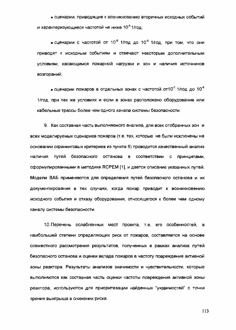
• сценарии, приводящие к возникновению вторичных исходных событий
и характеризующиеся частотой не ниже 10"51/год;
• сценарии с частотой от 10"6 1/год до 10"5 1/год, при том, что они
приводят к исходным событиям и отвечают некоторым дополнительным
условиям, касающимся пожарной нагрузки и зон и наличия источников
возгораний;
• сценарии пожаров в отдельных зонах с частотой отЮ'71/год до 10"6
1/год, при тех же условиях и если в зонах расположено оборудование или
кабельные трассы более чем одного канала системы безопасности.
9. Как составная часть выполняемого анализа, для всех отобранных зон и
всех моделируемых сценариев пожаров (т.е. тех, которые не были исключены на
основании скрининговых критериев из пункта 8) проводится качественный анализ
наличия путей безопасного останова в соответствии с принципами,
сформулированными в методике RCPEM [1], и дается описание указанных путей.
Модели ВАБ применяются для определения путей безопасного останова и их
документирования в тех случаях, когда пожар приводит к возникновению
исходного события и отказу оборудования, относящегося к более чем одному
каналу системы безопасности.
10. Перечень ослабленных мест проекта, т.е. его особенностей, в
наибольшей степени определяющих риск от пожаров, составляется на основе
совместного рассмотрения результатов, полученных в рамках анализа путей
безопасного останова и оценки вклада пожаров в частоту повреждения активной
зоны реактора. Результаты анализов значимости и чувствительности, которые
выполняются как составная часть оценки частоты повреждения активной зоны
реактора, используются для приоритезации найденных "уязвимостей" с точки
зрения выигрыша в снижении риска.
113
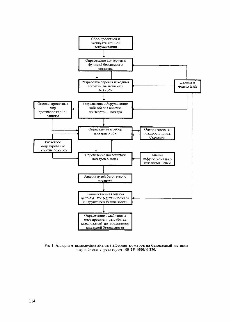
Сбор проектной иэксплуатационной
документации
Определение критериев ифункций безопасного
останова
Разработка перечня исходныхсобытий, вызываемых
пожаром
Оценка проектныхмер
противопожарнойзащиты
Определение оборудования/кабелей для анализапоследствий пожара
Расчетноемоделирование
развития пожаров
Определение и отборпожарных зон
Определение последствийпожаров в зонах
Анализ путей безопасногоостанова
Количественная оценкачастоты последствий пожара
с нарушением безопасности
Определение ослабленныхмест проекта и разработка
предложений по повышениюпожарной безопасности
Данные имодели ВАБ
Оценка частотыпожаров в зонах.
Скрининг
Анализнефункциональносвязанных цепей
Рис 1 Алгоритм выполнения анализа влияния пожаров на безопасный остановэнергоблока с реактором ВВЭР-1000/В-320/
114

Изложенный выше подход по существу объединяет вероятностный и
детерминистический методы анализа, сохраняя преимущества каждого из них. При
этом следует подчеркнуть, что в отличие от традиционного детерминистического
анализа безопасного останова, определение последствий пожаров и поиск путей
безопасного останова в соответствии с данным подходом производится на более
глубокой основе с привлечением моделей ВАБ. На последующей стадии работы
после уточнения недостающей информации, касающейся вероятностных аспектов
моделирования сценариев пожаров, возможен переход на полномасштабную
вероятностную модель безопасного останова.
Алгоритм выполнения анализа влияния пожаров на безопасный останов
энергоблока с использованием изложенного выше подхода приведен на рис.1.
4. РЕЗУЛЬТАТЫ АНАЛИЗА, ПОЛУЧЕННЫЕ К НАСТОЯЩЕМУ ВРЕМЕНИ
В процессе анализа получены следующие основные результаты:
1. Проведен анализ активных и пассивных противопожарных
средств и на его основе определены границы пожарных зон. Общее
число пожарных зон превышает 150 на энергоблок. Наличие источников
возгораний, горючих материалов, оборудования систем, выполняющих
приведенные выше функции безопасного останова, а также
оборудование, отказы которого приводят к исходным событиям аварии
являлось основным фактором при отборе помещений блока для их
последующей группировки в пожарные зоны (т.е. совокупностей
помещений, ограниченных пожаростойкими барьерами или свободной
территорией). Предполагалось, что локализация пожаров происходит в
границах пожарных зон, которые для этого должны обладать
достаточной степенью огнестойкости.
115
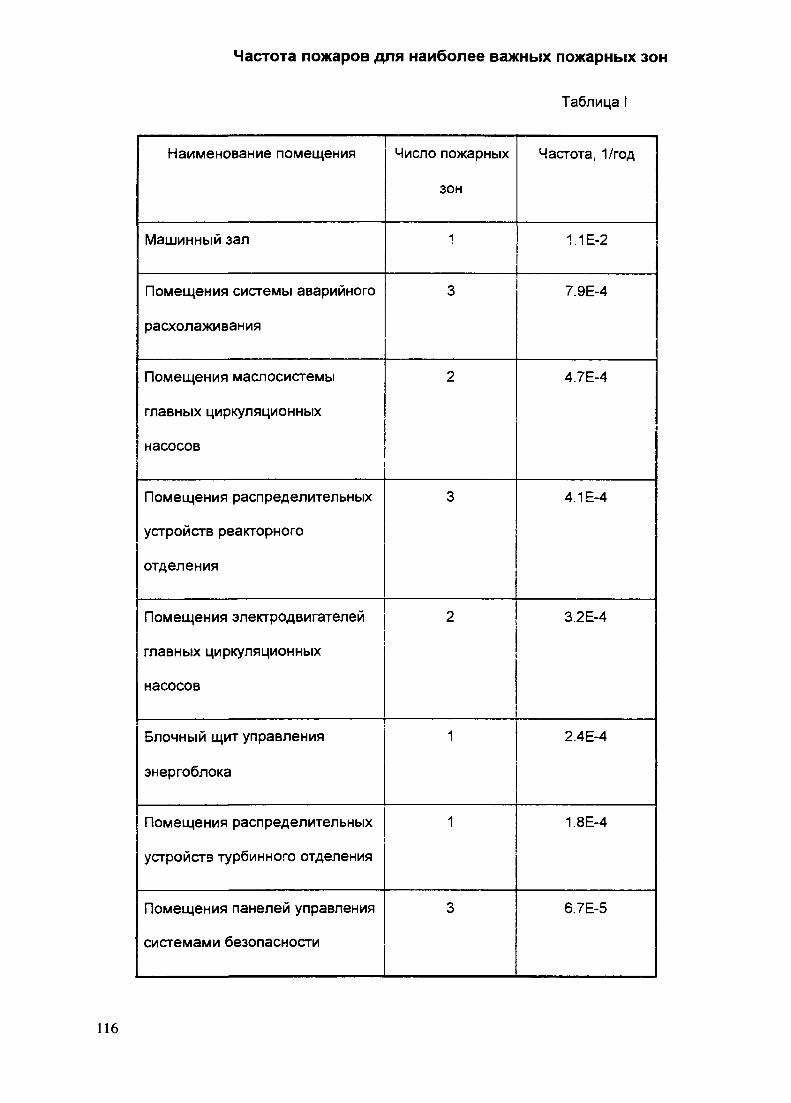
Частота пожаров для наиболее важных пожарных зон
Таблица
Наименование помещения
Машинный зал
Помещения системы аварийного
расхолаживания
Помещения маслосистемы
главных циркуляционных
насосов
Помещения распределительных
устройств реакторного
отделения
Помещения электродвигателей
главных циркуляционных
насосов
Блочный щит управления
энергоблока
Помещения распределительных
устройств турбинного отделения
Помещения панелей управления
системами безопасности
Число пожарных
зон
1
3
2
3
2
1
1
3
Частота, 1/год
1.1Е-2
7.9Е-4
4.7Е-4
4.1Е-4
3.2Е-4
2.4Е-4
1.8Е-4
6.7Е-5
116
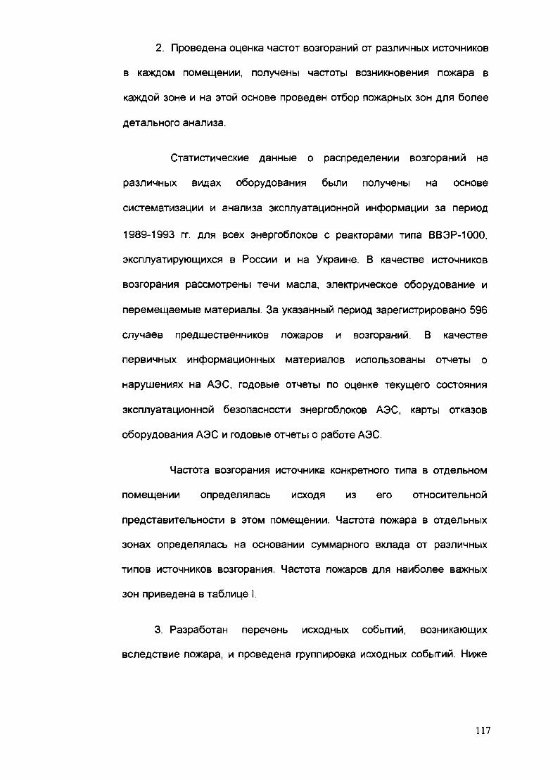
2. Проведена оценка частот возгораний от различных источников
в каждом помещении, получены частоты возникновения пожара в
каждой зоне и на этой основе проведен отбор пожарных зон для более
детального анализа.
Статистические данные о распределении возгораний на
различных видах оборудования были получены на основе
систематизации и анализа эксплуатационной информации за период
1989-1993 гг. для всех энергоблоков с реакторами типа ВВЭР-1000,
эксплуатирующихся в России и на Украине. В качестве источников
возгорания рассмотрены течи масла, электрическое оборудование и
перемещаемые материалы. За указанный период зарегистрировано 596
случаев предшественников пожаров и возгораний. В качестве
первичных информационных материалов использованы отчеты о
нарушениях на АЭС, годовые отчеты по оценке текущего состояния
эксплуатационной безопасности энергоблоков АЭС, карты отказов
оборудования АЭС и годовые отчеты о работе АЭС.
Частота возгорания источника конкретного типа в отдельном
помещении определялась исходя из его относительной
представительности в этом помещении. Частота пожара в отдельных
зонах определялась на основании суммарного вклада от различных
типов источников возгорания. Частота пожаров для наиболее важных
зон приведена в таблице I.
3. Разработан перечень исходных событий, возникающих
вследствие пожара, и проведена группировка исходных событий. Ниже
117

перечислены группы исходных событий, которые могут возникнуть по
отдельности или в сочетаниях вследствие пожара:
• останов реактора;
• нарушения нормального отвода тепла через 2-й контур в
различных конфигурациях;
а течь из первого контура через уплотнение главных
циркуляционных насосов;
• межсистемная течь из первого контура;
• отключение главных циркуляционных насосов;
• открытие предохранительных клапанов компенсатора
давления;
• открытие паросбросных клапанов БРУ-А или
предохранительных клапанов парогенераторов;
• обесточивание энергоблока (потеря источников третьей
категории собственных нужд).
4. Разработан перечень функций безопасности, выполнение
которых необходимо при различных исходных событиях, вызванных
пожаром, для приведения энергоблока в безопасное состояние. При
этом под безопасным состоянием блока понималось состояние горячего
останова, при котором отвод остаточных тепловыделений может
стабильно поддерживаться в течение 24 часов предусмотренными в
проекте системами без экстренных действий оперативного персонала по
переключению оборудования, а также состояние расхоложенного блока.
Для преодоления последствий указанных выше исходных событий
118

аварии рассматривались функции безопасного останова,
перечисленные ниже:
• приведение и поддержание реактора в подкритичном
состоянии;
• поддержание запаса теплоносителя в активной зоне реактора
при высоком, среднем и низком давлениях в 1-м контуре;
• отвод тепла через 1 -й контур при среднем и низком давлениях,
длительный отвод тепла и расхолаживание блока;
• обеспечение герметичности защитной оболочки с целью
предотвращения потери среды 1 -го контура;
• отвод остаточных тепловыделений и расхолаживание через
2-й контур;
• ограничение роста давления во 2-м контуре,
• обеспечение плотности главного парового коллектора и
паропроводов острого пара, изоляция парогенераторов по питательной
воде.
5. Разработан перечень систем и компонентов, выполняющих
функции безопасного останова при пожаре, и проведен анализ их
отказов. Указанные функции могут выполняться как штатными
системами так и системами безопасности. Дополнительно в число
функций безопасного останова могут быть включены действия,
выполняющиеся в качестве мер по управлению запроектными авариями
в случае отказа предусмотренных в проекте нормальных и аварийных
систем (например, подпитка реактора в режиме "feed and bleed").
Перечень систем и оборудования, отвечающий приведенным выше
функциям безопасного останова был составлен на основе моделей ВАБ.
119

6. Проведен анализ ассоциированных цепей для выявления
неявных зависимостей, которые могут возникать при пожаре, а именно:
• вторичных возгораний трансформаторов тока,
• неселективного функционирования выключателей при
коротких замыканиях или замыканиях на промежуточную нагрузку,
• распространения пожара по кабельным трассам через
неогнестойкие проходки.
7. Проведено теплофизическое моделирование развития пожара
и его воздействия на строительные конструкции и оборудование для
ответственных помещений. Такие расчеты были выполнены для
машзала (пожар на турбине, сопровождающийся горением масла) и
кабельного коридора, примыкающего к помещениям всех трех каналов
системы безопасности. Результаты расчетов позволили подтвердить
приемлемость допущений, принятых в анализе для определения границ
указанных пожарных зон.
8. Проведен инженерный анализ последствий пожаров, в том
числе из-за коротких замыканий, обрывов и горячих замыканий силовых
и контрольных кабелей, приводящих к отключению или ложному
срабатыванию оборудования. Были проанализированы все возможные
последствия пожаров в пожарных зонах в терминах зависимых исходных
событий аварий и отказов элементов систем безопасного останова
(учитывались ложные срабатывания и отказы на требование). При
выборе моделируемых сценариев развития пожаров в зонах применялся
консервативный подход, который обеспечивает рассмотрение наиболее
тяжелого протекания аварии. В тех случаях, когда выбор наиболее
120

тяжелого сценария из нескольких возможных представлялся
затруднительным, рассматривались альтернативные сценарии, каждому
из которых отвечала определенная условная вероятность реализации.
К концу 1997 года планируется завершить разработку вероятностной модели
энергоблока и оценку вклада от пожаров в отдельных помещениях в частоту
повреждения активной зоны и окончательно определить "слабые" места в проекте
АЭС с ВВЭР-1000/320 с точки зрения обеспечения безопасности энергоблока при
пожаре.
5. ВЫВОДЫ
Анализ последствий пожаров на 4-м блоке Балаковской АЭС позволил
сделать следующие выводы:
1. АЭС с реактором ВВЭР-1000/В-320 обладает достаточно высокой
степенью противопожарной защиты, что объясняется последовательным
применением в проекте известных принципов безопасности (защита в глубину,
сочетание пассивных и активных средств, канальное построение систем
безопасности, физическое и электрическое разделение компонентов,
относящихся к разным каналам). Для рассматриваемого проекта невозможны
ситуации, приводящие к ядерно опасным режимам.
Пожары в ряде ответственных помещений (здание резервной
дизельной электростанции, блочного щита управления и др.) не приводят к
значимым с точки зрения безопасности последствиям. Так, пожар в здании
резервной дизельной электростанции, в силу принятых компоновочных решений
(расположение дизель-генераторов одного блока в разных зданиях), не приводит
к возникновению исходных событий и не может вызвать отказ всех каналов
121
систем безопасности. Пожар на блочном щите управления может привести к
появлению ложных импульсных (т.е. не обладающих памятью) сигналов,
вызывающих изменение состояний оборудования (срабатывание
предохранительной арматуры, остановку насосов, изменение состояния запорно-
регулирующей арматуры), однако, даже в случае возникновения множественных
коротких замыканий на блочном щите управления пожар не сможет повлиять на
работу автоматики энергоблока, которая обеспечит переключение оборудования
в безопасное состояние вследствие достижения значениями параметров
соответствующих уставок. Вместе с тем, оператор сохраняет возможность
выполнения всех необходимых функций безопасного останова блока с
резервного щита управления энергоблока, который электрически независим от
блочного щита управления.
2. В результате анализа были определены потенциально уязвимые, с
точки зрения последствий пожаров, зоны, дающие наибольший вклад в величину
риска. К числу указанных помещений относятся:
• помещения управляющих устройств УКТС;
• ряд кабельных шахт и полуэтажей;
• помещения датчиков КИП;
• зоны машинного зала (турбоустановка и участок размещения
турбопитательных и вспомогательных питательных насосов);
• помещения несистемных комплектных распределительных
устройств и агрегата бесперебойного питания.
Типовым последствием пожаров в системных помещениях реакторного
отделения является остановка блока по причине отключения главных
122

циркуляционных насосов с отказом одного канала всех систем безопасности. В
ряде зон указанное исходное событие осложняется отказом системы продувки-
подпитки, обеспечивающей подачу запирающей воды на уплотнения главных
циркуляционных насосов. В этих случаях авария при незакрытии оператором
дистанционно одной из задвижек на сливе запирающей воды переходит в группу
аварий с малой или средней течью из первого контура внутрь защитной
оболочки. Для приведения блока в безопасное состояние в этом случае может
быть использовано работоспособное оборудование в неповрежденных каналах
систем безопасности .
Наиболее критическим из числа системных помещений с точки зрения
последствий пожаров является помещение управляющих устройств УКТС 2-го
канала систем безопасности. Пожар в данной зоне может вызвать закрытие
быстродействующих запорно-отсечных клапанов на всех четырех
парогенераторах (по причине ложного формирования сигнала Ats>75), что
аналогично нарушению нормального отвода тепла через 2-й контур с потерей
технологического конденсатора. Указанное исходное событие сопровождается
остановкой главных циркуляционных насосов, потерей возможности подачи
питательной воды во 2-й и 3-й парогенераторы, а также отказом всего остального
оборудования 2-го канала систем безопасности. Предполагается, что наиболее
тяжелый сценарий протекания аварии имеет место в случае потери питания и
управления сбросных клапанов БРУ-А на 2-м и 3-м парогенераторах после их
открытия по повышению давления в парогенераторах, что приводит к фиксации
сбросных клапанов БРУ-А в открытом положении.
Опасность такой аварии состоит как в возможности захолаживания 1 -го
контура в начальный период ее протекания, так и значительного сокращения
располагаемых средств по расхолаживанию реакторной установки через 2-й
123

контур. Указанная авария в части непосадки двух сбросных клапанов БРУ-А
требует специального исследования для обоснования наиболее эффективного
способа приведения блока в безопасное состояние и последующей разработки
корректирующих мероприятий, например изменения схемы управления БРУ-А.
Аварии, вызванные пожарами в помещениях управляющих устройств УКТС 1-го и
3-го каналов систем безопасности, протекают аналогичным образом, однако, в
отличие от случая, рассмотренного выше, возможна непосадка только одного
сбросного клапана БРУ-А.
Последствием пожара в машзале (зона турбины) является, как было
отмечено выше, нарушение нормального отвода тепла через конденсатор
турбины. Вместе с тем анализ показал, что для приведения в действие
технологического конденсатора в режиме отвода остаточного тепла, необходимо
открытие арматуры, дистанционно управляемой с местного щита турбины, что,
учитывая ситуацию повышенного стресса, вызванного крупным пожаром на
турбоустановке, представляется трудноосуществимым. В этом предположении
последствием пожара для обеих зон машзала может явиться полная потеря
систем второго контура. Следует отметить, что относительный вклад указанной
аварии в риск значителен из-за большой частоты возникновения пожаров в
машзале, что требует дублирования управления этой арматурой с БЩУ.
Возможным последствием пожара в помещениях системного
комплектного распределительного устройства является обесточивание блока,
сопровождающееся остановкой главных циркуляционных насосов и штатных
систем нормальной эксплуатации. Однако, риск подобной аварии невелик, в
связи с малой пожарной нагрузкой этих помещений, что не требует
дополнительных мер по безопасности.
124

Следует отметить, что во всех указанных выше случаях возникновения
пожаров в помещениях АЭС за пределами реакторного отделения, системы
безопасности, запитанные от дизель-генераторов, не могут прямо или косвенно
быть повреждены в результате их действия.
3. На основе выводов, сделанных по предварительным итогам
проделанной работы, наиболее уязвимым местом проекта 4-го блока
Балаковской АЭС в пожарном отношении являются помещения управляющих
устройств УКТС. Следует также отметить, что снятие ограничений, налагаемых
общепринятым в настоящее время принципом единичного отказа для ложной
наводки напряжения в нормально обесточенных кабелях, может привести к
расширению спектра возможных исходных событий и последствий, в частности,
открытию арматуры на линии газоудаления из компенсатора давления, а также
более серьезной течи из первого контура через трубопровод системы планового
расхолаживания (в последнем случае необходима ложная запитка всех трех фаз
силового кабеля в определенном порядке). Вместе с тем, учитывая принимаемую
в настоящее время оценку условной вероятности такого типа событий (порядка
5*10"2 для одной жилы), следует ожидать, что подобные гипотетические аварии
не внесут значимый вклад в величину пожарного риска.
ЛИТЕРАТУРА
1. US Department of Energy Reactor Core Protection Evaluation Methodology for
Fires at Soviet-Designed RBMK and WER Nuclear Power Plants. Revision 0. US
Department of Energy, December 1996.
2. Швыряев Ю.В. и др. Вероятностный анализ безопасности атомных станций.
Методика выполнения. Ядерное общество СССР, Москва, 1992.
3. Final Level 1 PSA Report. Atomenergoproekt, TACIS 3.1. Project Ref.
C9225/AEP/REP/063 Issue V3 April 1996, Moscow.
125

IAEA-SM-345/36
invited Paper |„„||||„|,XA9847512
СРАВНИТЕЛЬНЫЙ АНАЛИЗ ОПАСНОСТЕЙ ОБЫЧНОГО ИНАТРИЕВОГО ПОЖАРА НА АЭСС БЫСТРЫМ РЕАКТОРОМ
В.Н. ИВАНЕНКО, Д.Ю. КАРДАШГНЦ РФ Физико-энергетический институтОбнинск, Российская Федерация
Abstract-Аннотация
COMPARATIVE ANALYSIS OF THE RISK OF ORDINARY AND SODIUMFIRES AT NUCLEAR POWER PLANTS WITH FAST REACTORS.
A specific feature of a fast reactor is the presence of sodium coolant. Liquid sodium is acombustible material and therefore if any leaks occur in the sodium loops, the escaping sodiummay ignite, releasing energy and smoke.
Sodium leaks and fires which have occurred in practice have not posed a threat to thenuclear or radiation safety of reactors. On the other hand, during the operation of thermal reac-tors, a number of serious fires have occurred, which caused extensive material damage and, ifthings had turned out badly, could have threatened reactor safety.
In this paper, the authors present a comparative analysis of the risk of ordinary and sodi-um fires in nuclear power plants. The characteristics of sodium and other combustible materi-als used in nuclear power plants are analysed [1]. The risk of different types of fires is consid-ered, taking into account features of specific reactor projects, including the location in the reac-tor building of fire protection systems and combustible material, the fire resistance of fire bar-riers (screening), and the operation of fire detection and extinguishing systems [2]. Methods ofsafety probability analysis are employed. It is concluded that the use of sodium at nuclear powerplants does not lead to an essential reduction in overall safety.
СРАВНИТЕЛЬНЫЙ АНАЛИЗ ОПАСНОСТЕЙ О Б Ы Ч Н О Г О И НАТРИЕВО-ГО ПОЖАРА НА АЭС С БЫСТРЫМ РЕАКТОРОМ.
Специфической особенностью быстрого реактора является наличие натриевоготеплоносителя. Жидкий натрий является горючим веществом, поэтому приразуплотнениях натриевых контуров возможно загорание вытекающего натрия свыделением энергии и дыма.
Случившиеся на практике течи и пожары натрия не создавали угрозы для ядернойили радиационной безопасности реакторов. С другой стороны, при эксплуатациитепловых реакторов произошел ряд крупных пожаров, которые причинили огромныйматериальный ущерб, а при неблагоприятном развитии событий могли угрожатьбезопасности реактора.
В настоящем докладе проводится сравнительный анализ опасности обычных инатриевых пожаров для АЭС Анализируются свойства натрия, а также другихматериалов, применяемых на АЭС, как горючих веществ [1]. Опасность различноговида пожаров рассматривается с учетом условий конкретных проектов реакторов, в томчисле расположения в здании реактора систем безопасности и горючих материалов,пожаростойкости противо-пожарных преград (перегородок), работы системобнаружения пожара и пожаротушения [2]. Применяются методы вероятностногоанализа безопас-ности. Делается вывод о том, что применение натрия на АЭС неприводит к кардинальному ухудшению ее общей безопасности.
127

1. ВВЕДЕНИЕ
Специфической особенностью быстрого реактора является наличиенатриевого теплоносителя. Жидкий натрий является горючим веществом.Температура натрия, находящегося в теплоотводящих контурах быстрого реактора вэксплуатационных режимах превышает его температуру самовоспламенения ввоздухе. Поэтому при разуплотнениях натриевых контуров возможно загораниевытекающего натрия с выделением тепла и дыма.
Способность натрия при рабочих температурах возгораться при контакте своздухом некоторыми специалистами представляется как серьезнейший недостатокэтого типа реакторов. На этом основании иногда даже формулируется утверждение оневозможности широкого развития АЭС с быстрыми натриевыми реакторами.
Однако отечественный и зарубежный опыт эксплуатации быстрых натриевыхреакторов (около 250 реакторолет) не подтверждает этого пессимистическоговывода. Случившиеся на практике течи и пожары натрия не создавали угрозы дляядерной или радиационной безопасности установок. Результаты теоретических иэкспериментальных исследовательских работ говорят о малой вероятности крупныхтечей и пожаров натрия на современных быстрых реакторах.
С другой стороны , при эксплуатации тепловых реакторов произошел рядкрупных пожаров ( например, на АЭС Браунз-Ферри в США в 1975 году ) , которыепричинили огромный материальный ущерб, а при неблагоприятном развитиисобытий могли угрожать безопасности реактора [ 1 ].
Отсюда логически возникает вопрос: насколько опасен натриевый пожар дляАЭС по сравнению с пожарами других видов горючих веществ? Рассмотрению этоговопроса посвящена настоящая работа.
2. ОПАСНОСТИ ОБЫЧНЫХ И НАТРИЕВЫХ ПОЖАРОВ
Атомная электростанция является ядерноопасным объектом. Поэтому любыеопасные события на АЭС, в том числе пожары следует рассматривать прежде всего сточки зрения их угрозы для ядерной безопасности.
Кроме того, пожар на АЭС, так же как и на любом другом объекте,представляет собой угрозу для людей, материальных ценностей, может повлечь засобой потери от простоя. Следует отметить, что в условиях атомной станции пожар,даже не угрожающий активной зоне реактора, может представить радиационнуюопасность, если в зоне горения находятся радиоактивные вещества ( например, припожарах в хранилищах сухих отходов, системах спецвентиляции, горениирадиоактивного натрия).
Повреждение активной зоны реактора вследствие пожара может произойтипри реализации следующих событий:
- разуплотнение первого контура, истечение теплоносителя и обнажениеактивной зоны, что может быть следствием разрушения вследствие пожарастроительных конструкций, опор и подвесок трубопроводов и оборудования первогоконтура;
- повреждение систем, обеспечивающих контроль и управление протеканиемцепной реакции;
- выход из строя систем аварийного расхолаживанияПричинами этих событий могут быть опасные факторы пожара, которые
воздействуют либо непосредственно на сооружения или системы, либо на
128

обслуживающий персонал. Опасные факторы пожара являются следствиемэнерговыделения при горении, выделения дыма и вредных газов, сжиганиякислорода.
При обычных пожарах выделяется огромное количество различных вредныхвеществ. Так, у пенополиуретанов идентифицировано примерно 50 токсичныхпродуктов горения, у поливинилхлорида около 75, причем некоторые из нихобладают канцерогенными свойствами. При горении полимерных материалов (изоляция проводов, материал плат в щитах управления ) выделяется хлористыйводород, оксид и диоксид углерода, цианистый водород, синильная кислота и другиетоксичные продукты горения [ 1 ] .
При горении натрия образуются его окислы ЫагО и NaiCh. Некоторая частьпродуктов горения выделяется в виде аэрозолей. Взаимодействуя с влагой воздуха,они довольно быстро превращаются в гидроокись NaOH. Это наиболее опасное изсоединений натрия. Предельно допустимая концентрация ( ПДК ) NaOH в России ввоздухе рабочей зоны равна 0,5 мг/м . В дальнейшем реагируя с углекислым газом
гидроокись постепенно переходит в карбонат ЫагСОз , для которого ПДКрз. ( ввоздухе рабочей зоны ) равна 2 мг/м3. Распространяясь в атмосфере, натриевыеаэрозоли оказывают воздействие на людей, находящихся на прилегающейтерритории. Для этого случая ПДК таковы: ПДКм р (максимальная разовая - втечение 30 минут ) равна 0,5 мг/м", а среднесуточная ПДКс.с. = 0,05 мг/м3 [ 2 ].
Воздействию натриевых пожаров на окружающую среду уделяется большоевнимание. Создан ряд вычислительных программ, позволяющих оценить эффектытакого воздействия. С помощью этих программ могут быть, в частности,установлены для каждого натриевого реактора предельно-допустимые выбросы(ПДВ) натриевых аэрозолей, соответствующие приведенным выше ПДК.
Обычные пожары загрязняют окружающую среду продуктами горения ипиролиза, несгоревшими горючими веществами, которые оказывают негативноевлияние на здоровье человека и экосистемы. Опыт обычных пожаров говорит о том,что в 80 -г 90 % случаев гибель людей при пожарах происходит от отравленияпродуктами горения [ 3 ]. Экологические последствия пожаров не ограничиваютсясмертельными исходами. Существует опасность возникновения различныхзаболеваний, вызванных выделением при пожарах различных токсических веществ.
Анализ показывает, что при обычных пожарах по многим токсическимвеществам ПДК превышаются на много порядков. Кроме того, в литературе имеютсяуказания на то, что не все токсиканты, образующиеся при пожарах выявлены, а срединевыявленных могут оказаться обладающие еще более сильным негативнымэффектом [ 3 ]. Таким образом, выброс в окружающую среду при обычных пожарахна АЭС токсичных и вредных продуктов горения представляют экологическуюопасность и должен серьезно анализироваться.
Выход токсичных продуктов при пожаре в аэрозольной или газовой форметакже зависит от количества сгоревшего вещества. Кроме того, каждое горючеевещество имеет свою долю выхода. Так, при горении натрия в аэрозоли переходит от10 до 30 % продуктов горения. При горении таких материалов как нефть инефтепродукты почти все сгоревшее вещество переходит в газоаэрозольную фазу.Считается, что массовая скорость дымообразования равна массовой скоростивыгорания материала [ 4 ].
Аэрозоли натрия даже в малых количествах вызывают раздражение слизистойоболочки. Это обстоятельство имеет и свою положительную сторону, т.к. позволяетобнаруживать малые протечки натрия обслуживающим персоналом. Известныслучаи, когда операторы обнаруживали натриевый пожар находясь на значительномотдалении от аварийного помещения.
129

ТАБЛИЦА 1. ТЕПЛОВЫЕ ЭФФЕКТЫ И СКОРОСТИ ГОРЕНИЯ НЕКОТОРЫХ МАТЕРИАЛОВ
Горючий материалили вещество
Бензин
Диз. топливо
Древесина
Мазут
Резина
Натрий
Скорость горения, кг/м2-ч
160-200
150
50
126
40
30-50
Тепловой эффект,кДж/кг
41870
41870
13800
38700
33500
10900
Сравнивая опасности обычного и натриевого дыма надо учитывать, чтонатриевые системы на атомных станциях расположены, как правило, в защитныхбоксах, а прочие горючие вещества имеются во всех рабочих помещениях.
При пожарах возникает угроза для строительных конструкций, обусловленнаятепловыми эффектами горения. В таблице 1 приведены тепловые эффекты иудельные скорости горения некоторых веществ, в том числе натрия. Из таблицывидно, что по этим параметрам натрий занимает одно из последних мест.
При горении натрия почти не образуется пламени. На рис.1 приведеносравнение температурных полей над горящими натрием и бензином и некоторыххарактеристик их горения [ 5 ].
Температурные эффекты при горении натрия вследствие этого существеннониже, чем при горении других материалов, применяемых на атомных станциях.Например, в работе [ 6 ] описаны полномасштабные эксперименты по изучениюпожаров кабелей с изоляцией из поливилхлорида. В этих экспериментахтемпература газа в помещении превысила 1000°С.
Многочисленные теоретические и экспериментальные исследования показали,что даже при крупных пожарах натрия температура газа в аварийном помещении непревышает 300°С и только в некоторых маловероятных ситуациях поднимаетсявыше этого значения.
Примером такой ситуации может быть горение натрия, истечение которогосопровождается образованием капель. В частности, исследования показали, чтонаиболее тяжелым является случай, когда вертикальная струя натрия распадаетсявследствие удара о потолок помещения или другую горизонтальную преграду,расположенную над местом течи. При этом эффекты горения оказываютсязначительными.
Подобная ситуация произошла на солнечной станции в Альмерии ( Испания )в 1986 году, в которой в качестве теплоносителя использовался натрий [ 7 ]. Попоследующим оценкам всего вытекло 13 - 15 м3 натрия. Течь продолжалась не менее15 минут. Это был самый большой ( как по масштабам, так и по последствиям ) изнатриевых пожаров, известных до сих пор. По проведенным впоследствии
130

м м
M M
/ " lOO C " \
/" зоо«с "N/^ 9оох: ч
4мм>
Зм^м
2»
1м
1НАТРИЙ
(пдямя отсутствует)
/зоохХ/ \
/ х 600^ х \
г/ ^ 800°С ^ Ч
х 900 ^С л. 1
1БЕНЗИН
(плаик достигает 4 м.)
Параметр
Скорость горения
Теплота горения(теплотворная
способность)
Скрытая теплотаиспарения
Пламя
Температура в 80 смот поверхности
Расход воздуха
на горение
Натрий
35 кг/м : ч
] 0 000 кДж/кг
3 800 к Д ж/к г
Пламяотсутствует
Меньше100 ° С
1 MV КГ
Бензин
120 кг/м2 ч
44 000 кДж/кг
350 кДж/кг
Высота пламенинесколько метров
800° С
Юм3/кг
Рис.1 . Сравнение параметров горения натрия и бензина.
и>

Системы индикациии очистки отпримесей
I
2
3
4
корпус реактора
страховочный кожух
запорные клапаны
электромагнитные насосы
Рис.2 . Схема подсоединения вспомогательных систем 1 контура.

косвенным оценкам температура в зоне горения ( распыла ) натрия достигалаприблизительно 1000 °С. Вне этой зоны температура была значительно ниже.
Подобные ситуации не характерны для инцидентов с течью натрия принормальных экплуатационных режимах натриевых систем быстрых реакторов.Развитие малой течи натрия в большую, связанное с катастрофическим разрушениемсистемы, происходит достаточно медленно. Малые течи натрия обнаруживаютсясистемами контроля, что позволяет предотвратить их развитие. Крупные течи сразбрызгиванием возможны при ремонтных работах, в основном как следствиегрубых ошибок персонала. По-видимому, их нужно анализировать отдельно отрассматриваемых в анализе безопасности проектных и запроектных аварий, т.к.вероятности их реализации при ремонтах и при нормальной эксплуатации резкоотличаются между собой.
Изложенное выше позволяет сделать следующие выводы:- натриевый пожар по выделяемым токсическим веществам при аналогичных
условиях не превышает опасность пожара других веществ, применяемых на АЭС;- тепловые эффекты натриевого пожара, как правило, существенно ниже, чем
обычного пожара и только при истечении с образованием капель приближается кнему.
3. КОМПОНОВКА СИСТЕМ БЫСТРОГО РЕАКТОРА
Схема теплоотвода быстрого реактора трехконтурная, т.е. между первым ипароводяным контурами располагается промежуточный натриевый контур.Современные проекты быстрых реакторов, как правило, предусматривают такназываемую интегральную компоновку 1-го контура. При этом почти весьрадиоактивный натрий размещается в баке реактора - сосуде с двойными стенками,пространство между которыми заполнено инертным газом. Это исключает горениенатрия.
Все натриевые системы расположены в отдельных боксах, где не допускаетсяпостоянное пребывание персонала. Помещения с радиоактивным натрием, исходя изтребований радиационной защиты, имеют железобетонные стены толщиной 1,5 - 2 м. В проектах предусматривается защита бетонных строительных конструкций отвоздействия натрия и тепловых эффектов путем создания облицовки стен и покрытияих теплоизоляцией. Многочисленными расчетами и экспериментами было показано,что течь и горение натрия не приводят к разрушению строительных конструкций.
В проектах быстрых реакторов предусматривается герметизация помещений снатрием. К ним не примыкают непосредственно помещения с постояннымпребыванием персонала, тем более с защитными, управляющими илиобеспечивающими системами безопасности. Вентиляция помещений с натриемосуществляется отдельными вентиляционными системами, которые никак не связаныс вентиляцией помещений с постоянным пребыванием персонала и с помещениями,где размещены системы безопасности.
4. СИСТЕМЫ ПОЖАРОТУШЕНИЯ НАТРИЯ
Для обнаружения возможных течей и горения натрия, а также дляпоследующего его тушения используются достаточно простые и надежныеустройства. Эти системы позволяют надежно обнаруживать факт течи и горениянатрия. Пожаротушение натрия обеспечивается в первую очередь пассивными
133
средствами, основанными на эффекте самотушения [ 8 ]. Используется герметизацияпомещений, что предотвращает натекание кислорода воздуха извне и обеспечиваетснижение концентрации кислорода до огнеопасного значения. Применяются системысливного пожаротушения, основным элементом которого являются емкости изнержавеющей стали, расположенные под технологическими помещениями, где впринципе возможны крупные выливы теплоносителя. Вылившийся натрийрасплавляет легкоплавкую мембрану, закрывающую дренажную линию, и самотекомсливается в емкости, где из-за недостатка кислорода гаснет. В других случаяхиспользуется система поддонов самотушения. Наконец, возможно применениеручных (огнетушители) или стационарных систем порошкового тушения.Отечественная и мировая практика показала достаточность этих мер.
5. ВЕРОЯТНОСТЬ КРУПНОЙ ТЕЧИ НАТРИЯ [ 9 ]
Ограждения помещений, в которых размещаются натриевые контуры,представляют собой локализующие системы безопасности. Развитие натриевогопожара, приводящее к угрозе для безопасности реактора, может быть связано с ихразрушением ( отказом ). Как уже сказано, они расчитаны на крупные течи натрия имогут быть повреждены только при наличии скрытого отказа ( например, крупныхтрещин ). Поэтому для опасного развития натриевого пожара необходимо наличиеследующих событий:
- крупный ( полный ) разрыв натриевого трубопровода;- отказ систем борьбы с натриевым пожаром;- разрушение строительных контструкций.Тем самым мы приходим к сценарию запроектной аварии.При анализе запроектных аварий рассматриеваемого типа принимается
полный разрыв натриевого трубопровода, хотя прочностные характеристики металлаи условия его работы таковы, что внутренних причин для подобных разрушений несуществует. Разрушение полным сечением может только в результате развитияначального малого дефекта и отсутствия контроля за протеканием этого процесса.
Наибольший интерес с точки зрения обеспечения безопасности АЭС вызываетрассмотрение аварии, связанной с течью радиоактивного натрия первого контура.Предполагается, что подобная течь возможна на трубопроводе вспомогательнойсистемы первого контура, не имеющего страховочного кожуха. На рис. 2. показанасхема подключения этой системы к баку реактора с интегральной компоновкойпервого контура.
Разгерметизация натриевого трубопровода полным сечением как исходноесобытие запроектной аварии возможна только в случае ряда отказов в системахбезопасности. На рис. 3. представлено соответствующее дерево отказов.
С учетом особенностей технологической схемы вспомогательных системпервого контура ( рис.2 ), принятого дерева отказов систем безопасности и иххарактеристик надежности была рассчитана вероятность исходного событиярассматриваемой аварии, которая оказалась равной 10 "5 1/реактор-год.
После разрыва трубопровода и излива натрия в бокс на дальнейшее развитиеаварии будет влиять только работа пассивных устройств, к которым относятся:
- клапан избыточного давления, отсекающий приточную вентиляцию приповышении давления в боксе. Однако поскольку повышение давления возможнотолько на начальной стадии процесса, то срабатывание клапана не учитывается
(идет в запас расчета ).
134

I Гильотинныйразрыв
5 Начальным1 дефект
Отказ клапа-нов на подаче натрия
Отказ клапа-I нов на возв
рате натрия!1
Отказ отсече-ния дефектного
участка
Отказ системыуправленияарматурой
Отсутствиесигнала
" пожар"
Отсутствие ручного управл.
арматурой
Рис. 3. Дерево отказов, приводящих к гильотинному разрывунатриевого трубопровода вспомогательной системыпервого контура .
- пассивные средства пожаротушения ( поддоны и расширяющиесяпорошковые составы ). Отказ пассивной системы имеет вероятность 10 "4.
Таким образом после наступления исходного события возможны два путиразвития аварии: со срабатыванием пассивных средств пожаротушения и с ихотказом. Для анализа принят второй путь, т.е. вероятность развития аварии по этомупути равна 10 "9 1/реактор год.
Для дальнейшего опасного развития событий необходимы очередные отказысистем безопасности. Это приводит к дальнейшему снижению его вероятности.Таким образом мы получаем, что вероятность ухудшения ядерной безопасностиреактора в результате натриевого пожара лежит в диапазоне остаточного риска.
135
6. ЗАКЛЮЧЕНИЕ
а) Для реально осуществимых аварийных ситуаций натриевый пожар не вноситкардинального вклада в общую пожарную опасность АЭС.б) Опасности натриевого пожара для обслуживающего персонала не превышаютопасностей от обычного пожара.в) Натриевый пожар не создает угрозы для ядерной безопасности реактора.
ЛИТЕРАТУРА
[ 1 ] МИКЕЕВ А.К. Противопожарная защита АЭС. М. , Энергоатомиздат, 1990.[ 2 ] БЕСПАМЯТНОВ Г.П. , КРОТОВ Ю.А. Предельно допустимые концентрациихимических веществ в окружающей среде. Л. , "Химия", 1985.[ 3 ] ИСАЕВА Л.К. .СЕРКОВ Б.Б. Экологические последствия загрязнения воздуха.Проблемы безопасности при чрезвычайных ситуациях. М. ВИНИТИ, 1992, вып.2,с.39.[ 4 ] МОНАХОВ В.Г. Методы исследования пожарной опасности веществ. М. ,"Химия", 1979.[ 5 ] LUCENET G. Le sodium, un metal apprivoise. Tire a part de la Revue Francaise del'Electricite№279, 1983.[ 6 ] SCHNEIDER U. Introduction to fire safety in Nuclear Power Plants. Nucl. Eng. Des.,v. 125, N3(Mar. 1991).[ 7 ] FREUDENSTEIN K.F. Effects of sodium fires on structures and materisls. Practicalexperience with sodium leakage accidents. Specialists' Meeting on Sodium Fires. Obninsk,June 6-9, 1988.[ 8 ] ВЫЛОМОВ В.В., ИВАНОВ Б.Г., ИВАНЕНКО В.Н. и др. Опыты по тушениюбольших количеств горящего натрия. Атомная энергия, т. 43, вып. 4 ( октябрь1977) стр. 286.[ 9 ] POPLAVSKY V.M., IVANENKO V.N., BAKLUSHIN R.P. Some aspects of fastreactor NPP safety connected with the use of sodium coolant. - In: Proc. Intern. TopicalMeeting on Sodium Fast Reactor Safety. Obninsk, Russia, October 3-7 1994, v. 3,p. 3-30*"- 3-39.
136

PANEL 1

Panel 1
IDENTIFICATION OF DEFICIENCIES INFIRE SAFETY IN NUCLEAR PLANTS
Chairperson: D.S. Mowrer (United States of America)
Members: M. Kaercher (France)M. Kazarians (United States of America)S. Lee (Canada)M. Rowekamp (Germany)
The panel was formed to discuss the most effective means of identifying fire safety deficienciesin nuclear power plants. The panel chairman and members included fire safety consultants andnuclear power plant designers. This discussion addressed three aspects of identifying deficiencies:
(1) Appropriate role and reliability of probabilistic safety analysis (PSA)(2) Most effective means of identifying deficiencies(3) Evaluation of human error aspects including manual fire fighting response
Fire PSAThe first question addressed to the panel concerned how the human error aspect of manual
fire fighting can be factored into a fire PSA. A panel member who is a specialist in fire riskassessment and PSA methodology development answered that the practical details of fighting the fire,including human error issues, typically are not factored effectively into the fire PSA. These analysestypically make conservative assumptions about the success of fighting the fire. Human errorconcerning operator actions at the control panel typically are factored into the analysis.
The next question was a clarification of the first: specifically, does the fire PSA assignprobabilities to the expected performance of the fire brigade? The PSA specialist on the panelanswered that the analyst typically will assign a probability for failure of the brigade to get there ontime, which involves having the right equipment with them, not tripping on the way to the fire, etc.This probability is largely determined based on the training aspects of fire fighting, including types ofdrills and available equipment.
The next topic concerned how the PSA analyst should approach plant managers about makingdecisions given the uncertainties inherent in a fire PSA. The specialist on the panel pointed out tworeasons why these analyses are performed: (1) alternative methods of obtaining the same informationas that yielded by a fire PSA can be more expensive than the PSA, and (2) the purpose of the fire PSAis to discover hidden or not-so-obvious chains of events which could happen. There was a certainamount of controversy expressed by the attendees regarding the cost-benefit of PSA methodologies,given the fairly wide uncertainty factors of one to two orders of magnitude. The fire PSA entails avery systematic analysis of what could possibly go wrong, and the nature of this analysis yields areasonable degree of certainty that all possible scenarios and contingencies have been considered.PSA essentially provides a way to articulate or organize knowledge about the fire risk; it does not addto that knowledge base. Any uncertainty arising from the PSA arises from uncertainty in theknowledge base; decisions are always made in the face of some uncertainty and this is no exception.This topic continued with an observation from the floor that plant managers and engineers may bereluctant to implement recommendations, or even to perform a fire PSA, because of (1) theuncertainties inherent in the fire PSA results; (2) the time and expense of performing a PSA; and (3)the nature of some recommendations arising from the PSA which might introduce only a slightimprovement to a system, process or area already operating within acceptable parameters.
139
Expanding on this topic of how to convince plant managers and engineers of the value of thefire PSA and its recommendations, a question was posed concerning the use of the PSA methodologyto improve public confidence in the current state of nuclear technology. The concern was that somedecision makers might use the PSA results to justify making no improvements, which seems to havebeen the case with a decision by ValueJet, based on the results of a PSA, to not put fire detection inthe cargo bay of :he plane which caught fire and crashed into a Florida swamp two years ago. Theanswer was that the ValueJet management, maintenance or pilot personnel should have had a betterknowledge base from which to provide input into the PSA. Convincing the public of nuclear safety isa cultural rather than a technical issue. The concern expressed by some attendees was that eventhough the existing database is very limited, PSA techniques are still being used—sometimesinappropriately.
Another cultural issue then was introduced concerning the use in the fire PSA of differentnumbers (probabilities) among the IAEA Member States. The PSA specialist on the panel suggestedthat plant personnel providing input to the PSA should be knowledgeable enough about the systemsand equipment to know if, for example, their pump is the same as one in a U.S. plant; if so, then U.S.numbers could be used. Another participant from the floor who has used PSA in making decisions atan electric utility recommended that the best application of PSA is as a supplemental tool used inaddition to good engineering judgment. Used in this way, PSA recommendations can assist decisionmakers in allocating limited budgetary resources, and this participant indicated that PSA is used asone of many decision making tools, rather than as a sole source of information. The ensuingdiscussion focused on what other tools are used when plant management is deciding onimprovements. Engineering judgment, supplemented with numerical support, is probably the mostprevalent tool.
Identifying DeficienciesThe next major topic to be introduced concerned the identification of fire safety deficiencies
in nuclear power plants. The first question asked was whether the visual and field inspection yieldsmore insight than the systematic analysis. A panel member with design, FHA and fire PSAexperience answered that general deficiencies are better identified using a systematic analysis, andproblems specific to a particular operation are better identified through visual inspection. Anotherpanel member stated that the main safety work gets done in the walkdown and that a very smallamount of added benefit comes from fire PSA. He then amended this with the observation that PSAmight be a useful tool for analyzing deficiencies, such as those associated with cables, which wouldnot necessarily be obvious during a walkdown. Another panel member pointed out that in hisexperience, the difference between actual knowledge gained from being in the plant and "paper"knowledge of the plant gained from design drawings and other documents viewed from outside theplant is probably two orders of magnitude of difference.
Manual Fire FightingThe topic of manual fire fighting was introduced as a reiteration of the question which began
the session (how manual fire fighting is factored into the fire PSA). Guidance was sought concerningthe time scale acceptable for off-site fire service to respond to a plant emergency beyond the plantbrigade capabilities. In addition, the question was posed: should the number of fire groups called in toassist correspond with the number or size of the fires, or with the number of reactors at a site? Theanswer given was that the presence of too many fire fighters introduces its own problems, forexample, because a limited number is allowed to enter into the containment area or because of alimited amount of fire fighting equipment (not to mention space limitations). Given these limitations,in addition to difficulty finding the fire to fight it and travel time for outside assistance, thisparticipant recommended that power plants rely more on passive barriers and firedetection/suppression systems, rather than excessive manual fire fighting resources, to assure firesafety of the plant in the first 10 or 15 minutes after fire detection. Another panel member expandedon this answer by emphasizing that very good coordination, as well as administrative controls, shouldstrongly regulate access to special areas. The control for nuclear safety should always be in the handsof the plant personnel.
140

This panel member again reiterated the question on how to consider the time for fire brigaderesponse when performing fire PSA. The orders of magnitude for success currently used areinternationally accepted but give very rough values. She then agreed with the importance of passivemeasures and automatic fire protection systems. Another panel member indicated that the Frenchplants rely mainly on passive fire barriers and very efficient detection systems. If manual fire fightingis anticipated for a particular area, then automatic suppression systems are installed to compensate forany limitations on the success of the brigade. Manual fire fighting is used with the aim, mainly, tolimit the costs of fire damage, rather than to assure plant fire safety.
Fire PSA RevisitedThe next question from the floor reintroduced the topic of fire PSA, and it concerned
comparing PSA results from plant to plant. Specifically, generic data gathered from other plants areused to supplement the lack of plant-specific data for a given fire PSA, and those generic data will bebased upon certain practices in the source plants. Should the plant performing the fire PSA complywith those practices in order to ensure a similar frequency of fire? The PSA specialist on the panelanswered that in the nuclear industry, within a given country the variation from plant to plant is notthat huge, but if a certain room in a plant has a feature significantly different from a comparable roomin other plants, then generic data should not be used. Another panel member dissented with thisopinion, offering his own opinion that plants and specific rooms are much too different to compare,regardless of whether the point of comparison is ignition frequencies or risk results.
Another question was posed about whether the shortcomings of fire PSA are due more to thedeficiency of the analyst or methodology or to the unavailability of appropriate data. In other words,should PSA specialists concentrate on better applications and existing methodologies or on a moreextensive collection system and use of operational experience? The answer given was that operationalexperience should always be collected because it forms the true knowledge base, which is continuallyexpanding. What PSA analysts should focus on is the chain of events, and all possible chains ofevents, which could lead to a fire in a particular area.
SummaryThe salient opinions which emerged during this panel discussion were as follows: (1) Given
the inherent uncertainty within fire PSA, this methodology should be used only as one of severaldecision making tools, including probably the most prevalent, engineering judgment. This judgmentshould be incorporated into the PSA process, especially when generic data and probabilities drawnfrom other plants are used to assign probabilities. The focus of the PSA should be on the chains ofevents which could cause a fire. (2) From a theoretical standpoint, a systematic approach such as firePSA seems to be very effective for identifying general deficiencies within a plant or deficiencies thatwould not be visible or obvious during an inspection. However, from a practical standpoint, awalkdown/inspection is the most effective means for identifying deficiencies related to particularprocesses or areas. (3) Given the possibility of human error, one effective use of manual fire fightingis to limit the damage caused by a fire, rather than to ensure nuclear safety. Any outside assistancemust be coordinated and the safety of the plant must remain at all times in the hands of the plantpersonnel.
NEXTiett UiMiK 1 4 1

OPERATIONAL EXPERIENCE AND DATA
(Session 4)
Chairperson
M. ROWEKAMPGermany

IAEA-SM-345/40
Key Issues Papers
OPERATIONAL EXPERIENCE AND DATA XA9847513
M. ROWEKAMPGesellschaft fur Anlagen- und Reaktorsicherheit,Cologne, Germany
The operational experience of nuclear power plants (NPPs) worldwide has shown thatthe occurrence of fires is not very frequent, but not improbable. Furthermore, the analysis ofNPP fire incidents gives the impression that plant internal fires have the potential to causedamage of safety related equipment and therefore can significantly affect the nuclear plantsafety.
The presently available data sources on actual fire events at NPPs have not been properlymaintained and are often out of date. In some IAEA member states reporting of fire events is notcarried out systematically and/or needs improvement with regard to criteria, scope and format ofdata reporting. Further practical limitations of the databases result from the existing data sources(e.g. fire reporting systems) being not sufficiently detailed to allow for suitable extrapolation toplant and/or fire compartment specific conditions considered in plant specific analyses.
Discussions with fire safety experts and, in particular with analysts, have shown thateven the highly developed event reporting systems for NPPs are not able to give the informationthe analyst really needs for his assessment. It is nearly impossible to obtain information onminor fire related events and/or on precursor events such as electrical shorts leading to trippedbreakers or to blown fuses, overheating conditions of components, etc. This information is oftennot recorded in detail and the access to the data from plant operational records is often limited tothe plant/utility level.
Further deficiencies can be found with regard to the available data to support theassessment of various physical behaviour and effects phenomena.
At the time being, in many IAEA member states in the frame of safety reviews etc.activities with regard to probabilistic safety analyses (PSA) including fire PSA are carried out.Furthermore, approaches for risk oriented performance based fire safety standards andguidelines are being developed in some of the member states. The data used for such fire riskstudies have been identified as one of the relevant elements requiring enhancement. Aconsiderable part of the data needed for fire safety assessments and, in particular for fire PSA,are derived from operational experience.
The currently ongoing IAEA activities in the field of fire related operational experienceand data are focusing on preparing a technical document on "Collection of Fire Related Data atNPPs". The information provided in this document on the potential use of fire relatedoperational experience is intended to assist the plant/utility staff responsible for reporting of dataon fire related events as well as the analysts engaged in the fire safety assessment of NPPs.Furthermore, it could be useful for regulatory authorities in setting up requirements for reportingfire safety related events. The purpose of the document is giving assistance in making informeddecisions concerning the scope and format of data reporting and also in giving some advice ondatabase features and on data analysis/processing.
145

The problems and deficiencies with regard to the currently available data and theirapplication in the frame of deterministic as well as probabilistic fire hazard analyses are wellknown to the fire safety experts and analysts. For more effective future activities the communityof fire safety experts has to decide, which types of mainly experience based data have to begained for carrying out analyses on a realistic basis. Furthermore, an approach has to be chosenhow to make more data available without mentioning plant internal information which stillshould be limited to plant/utility internal use. Incentives have to be found for the utilities tocollect more detailed information on all types of fire and fire related events in NPPs consideringthe needs of the analysts.
146

IAEA-SM-345/39Invited Paper
СОСТОЯНИЕ ДЕЛ В ОБЛАСТИ ПОЖАРНОЙ БЕЗОПАСНОСТИНА АЭС РОССИИ - СТАТИСТИЧЕСКИЙ АНАЛИЗЭКСПЛУАТАЦИОННОГО ОПЫТА
В.Н. ДАВИДЕНКО ХА9847514
концерн "Росэнергоатом','
В.И. ПОГОРЕЛОВГоскоматомнадзор России
ГЕ. СОЛДАТОВВсероссийский институтпо эксплуатации АЭС
Москва, Российская Федерация
Abstract-Аннотация
F I R E SAFETY STATUS IN NUCLEAR POWER PLANTS IN RUSSIA: A STATIS-TICAL ANALYSIS OF OPERATIONAL EXPERIENCE.
This paper summarizes the current situation as regards the organization and implementa-tion of fire safety at nuclear power plants in Russia. The design status of fire-fighting systems innuclear power plants, and the principal measures for improving overall fire safety are described.A statistical analysis is given of fires in nuclear power plants in Russia over the last six years, aswell as examples of fires in nuclear power plants in the USSR which are of major significanceas regards plant safety.The main lessons learned, and the measures implemented to improve firesafety are summarized. Investigation of fires and reporting is discussed. Problems with the car-rying out of probabilistic safety assessments involving comprehensive assessment of the contri-bution of fires to the frequency of serious damage to the reactor core are examined. In addition,the improvement of fire-fighting systems is discussed.
СОСТОЯНИЕ ДЕЛ В ОБЛАСТИ ПОЖАРНОЙ Б Е З О П А С Н О С Т И Н АА Э С РОССИИ - СТАТИСТИЧЕСКИЙ АНАЛИЗ ЭКСПЛУАТАЦИОННОГООПЫТА.
В данном докладе обобщается реальное состояние дел по организации иобеспечению пожарной безопасности (ПБ) на АЭС России. Излагаются проектноесостояние систем пожаротушения на АЭС и основные мероприятия, направленные наповышение ПБ в целом. Приводится статистический анализ пожаров на АЭС России запоследние 6 лет, приводятся также примеры происшедших пожаров на АЭС СССР какнаиболее значимых для безопасности АЭС. Обобщаются основные уроки и меры посовершенствованию ПБ. Уделяется внимание вопросам расследования пожаров иотчетности. Излагаются вопросы проведения вероятностного анализа безопасности каккомплексной оценки по вкладу пожаров в частоту тяжелого повреждения активнойзоны реактора. Уделяется также внимание вопросам усовершенствования системпожаротушения.
147
1.ОБЩАЯ ЧАСТЬ
1.1 Организация работ по обеспечению пожарной безопасности на АЭС.
В соответствии с действующими нормативными документами Минатома
России ответственность за противопожарное состояние и своевременное
выполнение мероприятий на АЭС возложена на руководителей АЭС. Все
производственные здания и сооружения, административные корпуса, помещения
складов, территория и пр. закреплены за структурными подразделениями (цехами)
АЭС.
В соответствии с распорядительными документами министерства на всех
АЭС разработаны планы мероприятий по повышению ПБ на 1995-2000 годы.
Составляются также годовые графики выполнения противопожарных
мероприятий. Ежегодно областными структурами Государственной
противопожарной службы Министерства внутренних дел Росси (ГПС МВД РФ)
проводятся инспекции противопожарного состояния АЭС, в результатом чего
администрации АЭС выдаются предписывающие документы для устранения
выявленных замечаний, на основании чего на АЭС издаются распорядительные
документы, в которых назначаются сроки и ответственные за выполнение
мероприятий.
Перед каждым планово-предупредительным ремонтом (ППР)
Госпожнадзором России (МВД РФ) проводятся комиссионные проверки
противопожарного состояния блоков АЭС, результаты которых учитываются
ГАН РФ при вьщачи разрешения на пуск конкретного блока АЭС после ремонта.
На всех АЭС организованы инспекции ведомственного контроля за
обеспечением ПБ, которая проводит обследования состояния противопожарного
оборудования, технической документации, осуществляет контроль за
выполнением противопожарных мероприятий.
148

На АЭС организованы также пожарно-технические комиссии (ПТК) из
представителей административного пресонала, которые рассматривают
документы по реконструкции систем противопожарной защиты и ПБ в целом на
АЭС, периодически проводят осмотры зданий и сооружений, анализируют случаи
возникновений пожаров.
На АЭС еженедельно проводятся оперативные совещания по вопросам ПБ
и по выполнению противопожарных мероприятий. Организованы также
добровольные пожарные дружины (до 600 чел. на кождой АЭС).
На энергоблоках АЭС разработаны оперативные планы и карты
пожаротушения, в которых расписаны действия оперативного персонала при
возникновении пожаров (до прибытия специальных пожарных подразделений).
В соответствии с программами подготовки персонала по ПБ проводятся
учебно-тренировочные занятия совместно с пожарными подразделениями.
На АЭС введен также противопожарный режим (порядок оформления
огневых работ, курение и пр.).
Результатом работы различных вышеуказанных структур только в 1996
году было выявлено на АЭС России 19300 нарушений требований нормативной
документации по ПБ.
В техническом плане состояние ПБ на действующих и остановленых для
снятия с эксплуатации АЭС в настоящее время выглядит следующим образом.
На всех блоках АЭС все кабельные помещения, главные трансформаторы и
маслосистемы оборудованы автоматическими установками пожаротушения,
которые постоянно находятся в готовности к включению в автоматическом
режиме. В машинных залах установлены системы пожарного водопровода
высокого давления для подачи воды на лафетные стволы для орошения ферм и
колонн машзалов, смонтированы также сухие трубы. На всех АЭС имеется
система пожарного водопровода, охватывающая все здания и сооружения, с
149

установленными пожарными гидрантами, пожарными кранами, рукавами и
стволами. Имеются сифонные колодцы и пирсы для забора воды пожарной
автотехникой. Все помещения на АЭС оснащены первичными средствами
пожаротушения. В помещениях контроля и управления блоками АЭС, в
помещениях с электронной аппаратурой и в ряде других важных для безопасности
помещениях АЭС смонтирована автоматическая пожарная сигнализация и
установки газового пожаротушения.
В целях улучшения противопожарной защиты с 1989 года по настоящее
время выполнены основные мероприятия, направленные на повышение пожарной
безопасности, в частности:
- выполнены огнезащитные уплотнения кабельных проходок в кабелных
помещениях;
- завершены работы по покрытию кабельных трасс огнезащитным
составом;
- разделены кабельные потоки разных систем безопасности;
- выполнен подпор воздуха в помещениях управления блоками АЭС и
автоматизированных систем управления;
- проведена реконструкция дверей и перегородок в кабельных помещениях,
выполнено разделение протяженных корридоров и кабелных тоннелей на отсеки и
пр.
Часть запланированных мероприятий не было выполнено, в основном,
из-за отсутствия должного финансирования.
1.2. Статистический анализ пожаров на АЭС России.
В настоящее время в России действует 29 энергоблоков (9 АЭС) с
реакторными установками (РУ) различных типов с установленной электрической
мощностью 21242 Мвт (12% от установленной мощности всех электростанций
150

России), 4 блока остановлены для снятия их с эксплуатации (с наличием на
площадках отработавшего ядерного топлива). Владельцем ядерных установок
является Минатом России, который образовал 2 эксплуатирующие организации:
концерн "Росэнергоатом" (8 АЭС, 25 блоков) и "Ленинградская АЭС" (1 АЭС, 4
блока).
Как известно, построенные до 1994 года АЭС в России, проектировались в
соответствии с действующими на тот период общепромышленными нормами и
правилами, не отвечающих современным требованиям нормативных документов.
Мировая статистика происшедших пожаров на АЭС подтверждает, что они
могут возникнуть из-за незначительных отказов электрооборудования или из-за
несоблюдений требований противопожарного режима и могут привести к
тяжелейшим последствиям, вызвать отказы систем безопасности (СБ), нарушить
отвод остаточного тепловыделения РУ и привести к большим человеческим и
материальным потерям.
Значимые для безопасности пожары на Белоярской АЭС (1978г.), на
Армянской АЭС (1982г.), на Чернобьшьской АЭС (1991г.) и на ряде зарубежных
АЭС являются подтверждением вышесказанного.
Характерными примерами могут служить случаи происшедших пожаров на
АЭС бывшего СССР.
На блоке 2 Белоярской АЭС (АМБ-160 ) в последний день старого 1978 года
в результате разгерметизации маслопровода турбогенератора возник пожар в
машинном зале и распространился по кабельным трассам. К моменту прибытия
пожарной команды (через 6 минут после сообщения) перекрытие на площадью в
960 м2 машзала уже обрушилось. Пожаром были повреждены кабели и
электрические панели на отметке 12,3 и 16,4, а также панели в помещении
управления блоком (БЩУ-2) на отметке 20,0, что привело к потере контроля
реакторной установкой. Ликвидация пожара продолжалась 22 часа (при
151
температуре наружного воздуха -47С° . Пзже машзал был восстановлен, были
заменены выгоревшие кабели и блок 2 проработал до 1989 года, после чего был
остановлен для снятия с эксплуатации.
На блоке 1 Армянской АЭС (ВВЭР-440) загорание произошло в насосной
станции подъема воды (расположенной в мащзале) в результате короткого
замыкания на клеммах двигателя насоса. Огонь быстро распространился по
кабельным трассам машзала до отметки 9,6, в результате чего произошли
массовые короткие замыкания в силовых и контрольных кабелях, вызвавшие
взрыв с воспламенением трансформатора собственных нужд, пожар на
турбогенераторе и маслобаках. В результате пожара выгорели кабели на площади
400м2, было повреждено оборудование комплексных распредустройств (КРУ-бкВ)
в машзале, что привело к потере контроля реакторной установкой в течение 8
часов. Ликвидация пожара длилась в течение 5 часов.
Энергоблок 2 Чернобыльской АЭС (РБМК-1000) находился в режиме
подъема мощности (N=425 Мвт) после капитального ремонта, в работе находился
один из двух турбогенераторов (ТГ). Произошло короткое замыкание в кабеле
управления работой высоковольного воздушного выключателя, в результате чего
произошло его 3-х кратное включение с подачей напряжения на второй
(отключенный) генератор, что привело к термодинамическим воздействиям на
ротор генератора (непроектный режим асинхронного двигателя), появлению
вибрации на ТГ, выбросу и воспламенению водорода (водородное охлаждение
ротора генератора) и разливу масла из подшипников генератора. Возник пожар в
машинном зале. Реактор был аварийно остановлен оператором. Через 5 минут
оперативный персонал смены приступил к тушению пожара на ТГ с помощью
лафетных стволов, в это же время прибыла пожарная команда. Были применены
все имеющиеся средства пожаротушения в машинном зале блока, но пожар был
настолько сильным, что через 20 минут после его возникновения обрушилась
152
кровля машинного зала. В результате происшествия вышло из строя
оборудование важное для безопасности, в частности, по общей причине, было
потеряно управление питательными насосами (расположенных в машзале), что
привело к резкому снижению уровней питательной воды в барабанах-сепараторах
(ВС). Позже была организована подпитка циркуляционного контура с помощью
насосов докачки конденсата и насосов гидроуплотнений, уровни в БС были
восстановлены. Ликвидация пожара продолжалась в течение 5 часов. В результате
нанесенного большого материального ущерба блок 2 в эксплуатацию больше не
вводился.
Таким образом возникшее короткое замыкание в контрольном кабеле
привело к тяжелейшему пожару и выводу из строя энергоблока мощностью 1000
Мвт.
Эти и другие примеры говорят о многих причинах возникновения значимых
для безопасности пожаров. Во-первых - о недостатках проекта в части
выполнения главной электрической схемы открытых распределительных
устройств (ОРУ). Во-вторых - о применении горючих кабелей, масел, водородного
охлаждения генераторов. В-третьих, проектные металлические конструкции в
машзалах АЭС первого поколения не были расчитаны на их длительную
огнестойкость. В проектной документации эти (и другие) вопросы не были
проанализированы должным образом.
По данным Всемирной организации по эксплуатации АЭС, основные
эксплуатационные показатели (количество автоматических аварийных остановов
РУ, коллективная доза облучения персонала, готовность систем безопасности,
количество пожаров и пр.) большинства АЭС России, на которых были внедрены
мероприятия по повышению ПБ, находятся на уровне зарубежных АЭС.
Вместе с тем, в ближайшие годы большинство энергоблоков АЭС России
выработают свой эксплуатационный ресурс (Таблица I), а их модернизация и
153
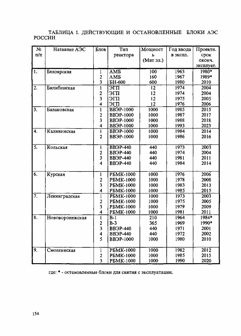
ТАБЛИЦА I. ДЕЙСТВУЮЩИЕ И ОСТАНОВЛЕННЫЕРОССИИ
БЛОКИ АЭС
№
п/п
1.
2.
3.
4.
5.
6.
7.
8.
9.
Название АЭС
Белоярская
Билибинская
Балаковская
Калининская
Кольская
Курская
Ленинградская
Нововоронежская
Смолен иская
Блок
1231234123412
1234
1234123412345
123
Типреактора
АМБАМББН-600ЭГПЭГПЭГПЭГПВВЭР-1000ВВЭР-1000ВВЭР-1000ВВЭР-1000ВВЭР-1000ВВЭР-1000
ВВЭР-440ВВЭР-440ВВЭР-440ВВЭР-440
РБМК-1000РБМК-1000РБМК-1000РБМК-1000РБМК-1000РБМК-1000РБМК-1000РБМК-1000В-1В-3ВВЭР-440ВВЭР-440ВВЭР-1000
РБМК-1000РБМК-1000РБМК-1000
Мощность
(Мвт эл.)
10016060012121212
100010001000100010001000
440440440440
100010001000100010001000100010002103654404401000
100010001000
Год вводав экспл.
1963196719801974197419751976198519871988199319841986
1973197419811984
1976197819831985197319751979198119641969197119721980
198219851990
Проектн.срок
оконч.эксплуат.
1980*1989*20102004200420052006201520172018202320142016
2003200420112014
200620082013201520032005200920111984*1990*200120022010
201220152020
где: * - остановленные блоки для снятия с эксплуатации.
154
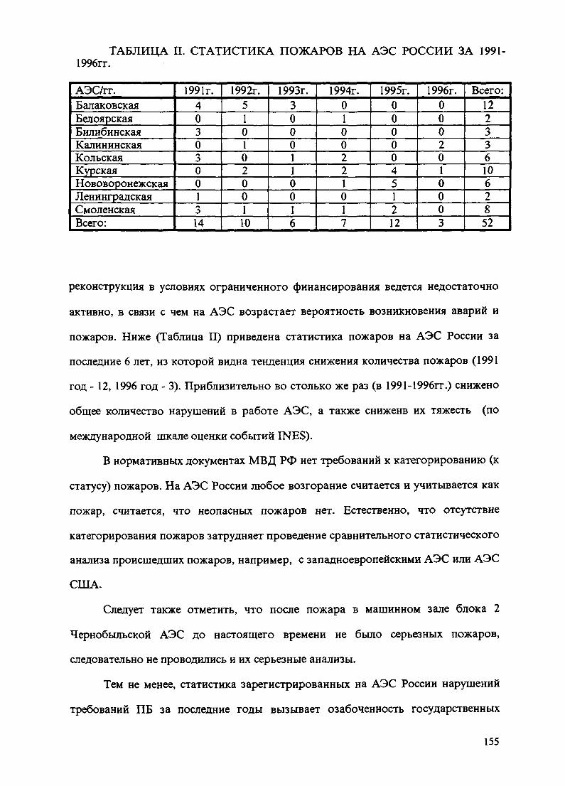
ТАБЛИЦА II. СТАТИСТИКА ПОЖАРОВ НА АЭС РОССИИ ЗА 1991-1996гг.
АЭС/гг.БалаковскаяБелоярскаяБилибинскаяКалининскаяКольскаяКурскаяНововоронежскаяЛенинградскаяСмоленскаяВсего:
1991г.40303001314
1992г.510102001
10
1993г.3000110016
1994г.0100221017
1995г.00000451212
1996г.0002010003
Всего:12233610628
52
реконструкция в условиях ограниченного финансирования ведется недостаточно
активно, в связи с чем на АЭС возрастает вероятность возникновения аварий и
пожаров. Ниже (Таблица II) приведена статистика пожаров на АЭС России за
последние 6 лет, из которой видна тенденция снижения количества пожаров (1991
год - 12, 1996 год - 3). Приблизительно во столько же раз (в 1991-1996гг.) снижено
общее количество нарушений в работе АЭС, а также сниженв их тяжесть (по
международной шкале оценки событий INES).
В нормативных документах МВД РФ нет требований к категорированию (к
статусу) пожаров. На АЭС России любое возгорание считается и учитывается как
пожар, считается, что неопасных пожаров нет. Естественно, что отсутствие
категорирования пожаров затрудняет проведение сравнительного статистического
анализа происшедших пожаров, например, с западноевропейскими АЭС или АЭС
США.
Следует также отметить, что после пожара в машинном зале блока 2
Чернобыльской АЭС до настоящего времени не было серьезных пожаров,
следовательно не проводились и их серьезные анализы.
Тем не менее, статистика зарегистрированных на АЭС России нарушений
требований ПБ за последние годы вызывает озабоченность государственных
155

регулирующих органов, так как любое выявленное нарушение противопожарных
требований может привести к реальному пожару, в том числе к значимому для
безопасности АЭС. В основном, приведенная статистика выявленных нарушений
не относится к системам важным для безопасности. Например, в 1995 году из ряда
выявленных нарушений только 2,4% нарушений относятся к помещениям, где
расположены системы, важные для безопасности.
Наибольшее количество пожаров за последние 6 лет произошло на
Балаковской АЭС (4x1000 Мвт, ВВЭР-1000), Курской АЭС (4x1000 Мвт, РБМК-
1000) и Смоленской АЭС (3x1000 Мвт, РБМК-1000) в количествах 12, 10 и 8
случаев соответственно. Из 12 пожаров, происшедших на АЭС России в 1995 году,
2 пожара возникли в помещениях машинных залов, где в значительном количестве
находятся системы, важные для безопасности АЭС.
Подавляющее большинство пожаров ( в процентном выражении)
происходит по причинам нарушения персоналом требований пожарной
безопасности (в основном, несоблюдение правил при производстве огневых и
пожароопасных работ), из-за неисправности технологического оборудования и
нарушения технологического процесса.
1.3. Основные уроки, вытекающие из опыта эксплуатации АЭС и
принимаемые меры.
Серьезные пожары на АЭС бывшего СССР, часть примеров которых была
приведена выше, послужили основой для переосмысления концептуального
подхода к обеспечению пожаробезопасности АЭС. Упор был сделан, в первую
очередь, на совершенствование нормативной базы, в результате чего вскоре был
разработан новый регулирующий документ "Общие положения обеспечения
безопасности атомных станций" (ОПБ-88), в основу которого была положена
первая концепция обеспечения безопасности АЭС. Были также введены новые
противопожарные нормы проектирования АЭС. На уровне Совета Министров
156

СССР были разработаны первоочередные мероприятия по пожарной
безопасности (СМПБ-88), направленные на замену горючих материалов,
покрытие кабельных трасс и несущих металлических, колонн в машзале
огнезащитным составом, совершенствование самих систем обнаружения пожаров
и пожаротушения. К выполнению данных мероприятий были задействованы ряд
министерств и ведомств, научно-исследовательские институты, проектно-
конструкторские организации и непосредственно АЭС. Часть мероприятий еще
находится в стадии выполнения. Была введена новая система подготовки
персонала АЭС по пожарной безопасности, были также пересмотрены вопросы
организации и профилактики противопожарной защиты. Усилился контроль за
обеспечением ПБ со стороны ГАН РФ и ГУПО МВД СССР.
В начале 90-х годов началось сотрудничество по вопросам повышения ПБ
на АЭС с зарубежными странами, обладающими развитой ядерной энергетикой.
В настоящее время, основываясь на документы МАГАТЭ и Министерства
энергетики США, заканчивается разработка новой концепции противопожарной
защиты АЭС и методик выполнения анализа влияния пожаров и их последствий на
безопасный останов реакторной установки. При финансовой поддержке
зарубежных стран на АЭС России выполняется вероятностный анализ
безопасного останова реактора при пожаре. Будут также разработаны
вероятностные модели, описывающие поведение энергоблока вследствие пожара,
а также возможные пути его приведения в безопасное состояние. Модели будут
представлять собой деревья отказов систем АЭС и деревья событий в виде
логических диаграмм развития аварий.
1.4 Расследование пожаров и отчетность.
Каждый происшедший на территории АЭС пожар расследуется и
учитывается в соответствии с нормативными документами как в системе ГПС
МВД РФ так и в системе Минатома России.
157
Цель служебного расследования состоит в выяснении обстоятельств,
непосредственных и коренных причин, условий, способствующих возникновению
и развитию пожара, а также последствий и величины нанесенного ущерба.
Сообщение о пожаре, явившимся причиной или следствием нарушения в
работе АЭС, передается в Минатом России, ГАН РФ, ГПС МВД Рф и в другие
организации в соответствии с нормативным документам "Положение о порядке
расследования и учета нарушений в работе Атомных станций" (ПН ПЭ Г-005-12-
91) а в случае угрозы безопасности АЭС передача информации министерствам и
ведомствам производится в соответствии с "Положением о порядке объявления
аварийной обстановки, передачи оперативной информации и организации
экстренной помощи атомным станциям в случае радиационно-опасных ситуаций
или аварий".
После ликвидации пожара руководство АЭС оценивает характер пожара и
его последствия для уточнения состава комиссии по расследованию инцидента. Во
всех случаях расследования пожара назначается комиссия. Пожар, который не
был связан с нарушением в работе АЭС расследуется комиссией, назначенной
приказом директора АЭС. В состав комиссии включаются инспектор, отвечающий
за состояние пожарной безопасности на АЭС, представители от ГПС МВД РФ,
ГАН РФ (по их требованию), руководители подразделений АЭС. Председателем
комиссии назн ачается главный инженер АЭС.
Результатом работы комиссии является акт расследования пожара (в
некоторых случаях комиссия направляет материалы в прокуратуру для
возбуждения уголовного дела), в котором излагаются основные и коренные
причины возникновения пожара и предложены мероприятия по улучшению
состояния ПБ. В соответствии с актом расследования администрацией АЭС
издается распорядительный документ, который устанавливает сроки и
ответственность за выполнение противопожарных мероприятий.
158

Ежегодно администрацией АЭС, по согласованию с местными органами
ГПС МВД РФ, редставляются в эксплуатирующие организации отчеты о
происшедших за прошедший год пожарах.
Ежеквартально, в соответствии с руководящими документами,
территориальные военизированные подразделения МВД РФ, непосредственно
ликвидирующие пожары, отчитывается перед областными структурами ГПС МВД
РФ, которые в свою очередь дважды в году отчитываются перед своим
центральным аппаратом.
В соответствии с "Положением о лицензировании деятельности в области
использования атомнаой энергии" для получения лицензии на вид деятельности
эксплуатирующая организация, при направлении в ГАН РФ (в составе материалов
обосновывающих безопасность АЭС) представляет отчет по противопожарной
защите АЭС, который кроме общих положений содержит такие разделы, как:
- организация противопожарной защиты при эксплуатации АЭС
(нормативно-техническая база, организационно-профилактическая работа,
государственный противопожарный надзор, ведомственный контроль,
технические средства пожаротушения, подготовка персонала, пожарная команда и
дрО;
- состояние работ по анализу влияния пожаров на безопасность АЭС;
- основные мероприятия по повышению ПБ.
Банки данных по пожарам на АЭС ведутся как на районном, так и на
областном уровне в системе ГПС МВД РФ. В настоящее время в в центральном
аппарате ГПС МВД РФ и в эксплуатирующих организациях создаются
централизованные банки данных.
В случаях значимых для безопасности АЭС пожаров, информация о
причинах и результатах расследований распространяется эксплуатирующими
организациями среди других АЭС в виде информационных писем с
159
соответствующими рекомендациями по недопущению аналогичных инцидентов.
Аналогичная информация распространяется областной структурой ГПС МВД РФ
среди подразделений системы.
7.5. Усовершенствование систем пожаротушения.
Опыт эксплуатации систем пожаротушения на АЭС показал их как
положительную сторону, так и их несовершенство. Последнее относится к так
называемым блокам АЭС первого поколения, проекты систем пожаротушения
которых разрабатывались в 60-е годы в соответствии с общепромышленными
нормами и правилами. На этих блоках в настоящее время ведется так называемый
"особый режим" эксплуатации.
Радикальное совершенствование систем пожаротушения проводилось
совместно с мероприятиями по повышению пожарной безопасности и проводится
в настоящее время в рамках графиков по техперевооружению и модернизации
блоков АЭС. В частности, на АЭС:
- проведена реконструкция пожарных водопроводов высокого давления с
заменой запорной чугунной арматуры на стальную;
- установлены лафетные стволы в машзалах для охлаждения колонн и ферм
при пожаре;
- введены в работу установки водяного пожаротушения в помещениях
главных циркнасосов, подпиточных насосов и дизель-генераторных станций;
- реконструированы системы автоматической сигнализации с ориентацией
на адресную систему пожарной сигнализации;
- сооружены дополнительные пожарные станции и реконструированы
пожарные водоводы;
- сооружены помещения контроля ПБ оаздельно для блоков первого
поколения и последующих блоков и ряд других мероприятий, плановое внедрение
которых задерживается из-за отсутствия должного финансирования.
160

ТАБЛИЦА III. КОЛИЧЕСТВО УСТАНОВОК ПОЖАРОТУШЕНИЯ ИУСТРОЙСТВ СИГНАЛИЗАЦИИ ПО КАЖДОЙ АЭС
Системы / АЭС
Количество установокАТП, из них:- водяногопожаротушения;- газовогопожаротушения;- пенногопжаротушения;- в том числеабонировано в 1996г.Количеств установокАПС,- в т.ч.смонтированных в1996г.
БАЛ
429
387
42
0
2
96
1
БЕЛ
5
3
2
0
0
6
0
БИЛ
25
1
1
23
0
11
1
клн
124
119
5
0
6
27
2
кол
230
135
95
0
5
24
0
КУР
281
281
0
0
0
28
0
нво
155
54
0
101
0
54
0
смо
282
282
0
0
0
132
0
ЛЕН
414
253
34
61
24
98
1
Всего:
1945
1515
178
205
37
476
5
В таблице III приведено количество установок пожаротушения и устройств
сигнализации по каждой АЭС (по состоянию на конец 1996 года).
В 1996 году по сравнению с 1995 годом значительно уменьшилось
количество ложных срабатываний установок автоматической пожарной
сигнализации (1995г. - 407 случаев, в 1996 году - 203 случая) и автоматических
установок пожаротушения с пуском огнегасящего состава (1995г. - 29 случаев,
1996г. - 8 случаев).
Ведется соответствующая работа по совершенствованию систем
пожаротушения в рамках Лиссабонской инициативы и по линии Европейского
банка развития и реконструкции (ЕБРР). С ЕБРР ГАН РФ ведет работы по
организации экспертиз проектных решений, на основании которых выдаются
поэтапные разрешения на внедрение оборудования на АЭС, в том числе и систем
пожаротушения. В частности, при финансовой поддержке ЕБРР на Ленинградской
АЭС (РБМК-1000, 4Х1000МВт) внедряется система водяного автоматического
пожаротушения с применением центробежных насосов с дизельными приводами.
161

Запуск каждого дизельного привода будет осуществляться от индивидуальной
аккумуляторной батареи.
Трудно решаются проблемные вопросы с обеспечением эффективными
системами пожаротушения в помещениях АСУ ТП и электронных спецсистем.
Разработан ряд проектных альтернативных решений, одно из которых состоит в
организации локальных участков пожаротушения (на уровне отдельных шкафов,
панелей).
Естественно, что эффективная работа систем пожаротушения ожидается в
том случае, когда будет завершена реконструкция и модернизация всего
пожароопасного оборудования, кабельного хозяйства, замены горючих масел,
заменено покрытие кровель, пластиката и пр.
1.6. Применение вероятностных методов для анализа пожарной опасности и
оценки последствий пожаров.
В настоящее время существует два основных подхода к оценке влияния
пожаров на безопасность АЭС. Один из них предусматривает выполнение
вероятностного анализа безопасности (ВАБ). Указанный анализ представляет
собой комплексную оценку вклада пожаров на АЭС в частоту тяжелого
повреждения активной зоны реактора (ПАЗ) на основе получения оценок частот
возникновения пожаров в помещениях основных зданий АЭС и определения их
последствий в виде отказов оборудования, важного для безопасности,
приводящих к возникновению исходных событий аварий и нарушению функций,
необходимых для приведения блока в безопасное состояние при этих событиях.
Другой подход к решению указанной проблемы основан на применении
детерминистического метода анализа безопасного останова.
Этот метод характерен системным и единообразным подходом к
решению вопросов пожарной безопасности АЭС и позволяет находить
162

простой и эффективный, с точки зрения затрат, способ выбора мер,
обеспечивающих наибольшее снижение риска. При этом, несмотря на
значительный объем проводимого анализа, планирование последовательности
операций всего комплекса исследований дает возможность выявить сложную
систему взаимодействий и системные логические связи, такие как
расположение электрических кабелей и компонентов схемы станции и
одновременно выбрать максимально приемлемый путь устранения уязвимых
мест, применяя альтернативные стратегии.
Вместе с тем, этому подходу присущ ряд ограничений. Основными из них
являются следующие.
ВАБ в силу комплексности подхода является достаточно глубоким и
одновременно системным инструментом анализа пожарной опасности и оценки
последствий пожаров. Он, в принципе, позволяет определить полный перечень
факторов (отражающих специфические свойства проекта АЭС), в наибольшей
степени влияющих на величину частоты тяжелого повреждения активной зоны, а
также произвести их ранжировку по данному критерию. Преимуществом ВАБа
является также независимость результатов от какой-либо субъективно принятой
шкалы оценок последствий, что, напротив, характерно для детерминистического
анализа.
Вместе с тем, выполнение ВАБ для пожаров представляет собой достаточно
объемную и большую по затратам и времени задачу, включающую, в частности,
разработку вероятностной модели, описывающей поведение энергоблока при
возникновении исходных событий аварий, являющихся следствием пожаров, а
также возможных путей его приведения в безопасное состояние. Одной из задач
пожарного ВАБ является разработка баз данных по частотам пожаров в
помещениях, а также по вероятностным характеристикам надежности элементов
АЭС при пожарах, которые зависят от показателей огнестойкости оборудования и
163
тепловых нагрузок, возникающих в процессе пожара. Использование при
проведении ВАБ не отвечающих объекту анализа исходных данных может
существенно исказить как абсолютные так и относительные количественные его
результаты.
Наиболее адекватная и эффективная оценка влияния пожаров на
безопасность АЭС может быть получена путем разумного сочетания обоих
упомянутых подходов.
Такой подход наиболее целесообразен, когда уже имеются результаты
выполненного ранее ВАБ первого уровня для внутренних исходных событий
аварий. В данном случае принимается, что задачи разработки вероятностных
моделей и создания базы данных по показателям надежности компонентов АЭС,
не относящиеся к пожарам решены при проведении указанного ВАБ. Поэтому
основной объем работ в рамках пожарного анализа распределяется следующим
образом.
В его детерминистической части решаются задачи определения наиболее
важных свойств проекта, влияющих на его пожарную безопасность, выполняется
анализ помещений, производится отбор пожарных зон. Дополнительно в
несколько расширенном по сравнению этим подходом объеме производится
определение зависимых от пожара отказов компонентов систем, которые могут
быть использованы для приведения блока в безопасное состояние, а также
зависимых от пожара исходных событий аварий.
В вероятностной части анализа значительный объем работ приходится на
оценку частот пожаров в различных помещениях АЭС, а также разработку
вероятностных моделей для отражения реальных сценариев протекания пожаров
на блоке, т.е. с учетом оценки вероятностей различных возможных последствий.
Отдельными важными задачами также являются создание интерфейсных моделей,
необходимых для приведение в соответствие деревьев событий и отказов из ВАБ-1
164

к спектру последствий, определенных в результате детерминистического анализа и
собственно расчет частоты ПАЗ с анализом значимости основных вкладчиков в
риск.
Подобный подход применен в настоящее время при анализе
безопасного останова в случае пожара энергоблока № 4 Балаковской АЭС с
реактором ВВЭР-1000 (проект В-320). Эта работа выполняется специалистами
ВНИИАЭС, института Атомэнергопроект и Балаковской АЭС. Ее результаты
излагаются в отдельном докладе данного симпозиума.
2. ЗАКЛЮЧЕНИЕ
В течение последних 6-8 лет на АЭС России, в результате полученных
уроков после происшедших серьезных пожаров, усилиями структур Минатома
РФ, ГПС МВД РФ, ГАН РФ и других организаций проведена существенная
работа как по повышению пожаробезопасное™, так и по совершенствованию
систем пожаротушения действующих и стоящихся АЭС. Особое внимание уделено
системе подготовки персонала. За рассматриваемый период времени заметно
снижено как общее количество пожаров на АЭС, так и их тяжесть. Исходя из
опыта эксплуатации АЭС России можно с достаточной степенью вероятности
утверждать, что в настоящее время состояние дел в области обеспечения ПБ
приближается к уровню зарубежных АЭС и работа в данном направлении
продолжается.
Мероприятия по повышению пожарной безопасности являются основными
стратегическими планами АЭС и их выполнение находится под контролем
надзорных органов.
гаияп
NEXT РАС:
IAEA-SM-345/38Invited Paper
DEVELOPMENT OF A FIRE INCIDENT DATABASE XA9847515FOR THE UNITED STATES NUCLEAR POWER INDUSTRY
G. WILKSNuclear Electric Insurance Limited,Wilmington, Delaware,United States of America
Abstract
The Nuclear Power Industry in the United States has identified a need to develop andmaintain a comprehensive fire events database to support anticipated performance-based or risk-basedfire protection programs and regulations. These new programs will require accurate information onthe frequency, severity and consequences of fire events. Previous attempts to collect fire incidentdata had been made over the years for other purposes, but it was recognized that the detail and formof the data collected would be insufficient to support the new initiatives. Weaknesses in the earlierefforts included the inability in some cases to obtain fire incidents reports, inconsistent or incompleteinformation reported, and the inability to easily retrieve, sort, analyze and trend the data. The criticalelements identified for the new data collection efforts included a standardized fire incident reportform to assure consistent and accurate information, some mechanism to assure that all fire events arereported, and the ability to easily access the data for trending and analysis. In addition, the databasewould need to be unbiased and viewed as such by outside agencies. A new database is currently beingdeveloped that should meet all of these identified need.
BACKGROUND
Several years ago, the nuclear power industry in the United States began considering"performance-based" or "risk-based" approaches to many aspects of nuclear plant operationand equipment maintenance. In addition, the U.S. Nuclear Regulatory Commission (NRC)started reviewing performance-based or risk-informed regulation approaches to replace someof its traditionally prescriptive regulatory methods. Both the utility industry and the NRCidentified fire protection programs as a candidate for performance-based consideration.
When the industry began looking at performance based approaches to fire protection issues, itwas recognized very early in the process that a comprehensive fire events database would bean essential element needed to support these types of programs. Accurate information on thefrequency and severity of fire occurrences would be critical, and the database would need tobe viewed as comprehensive and unbiased by regulators and other outside agencies. Inaddition, the database must be directly available to any utility company or any utility industryorganization with a legitimate need to access the data.
There had been several previous efforts to collect utility industry fire incident information;however, each of those was found to have certain drawbacks. The Fire Protection Committeeof the Edison Electric Institute (EEI), a U.S. utility industry organization, has been collectingreports on utility fire incidents for many years. These narrative reports pertaining to bothnuclear and non-nuclear facilities are voluntarily submitted to promote information sharing,and are discussed by the EEI Fire Protection Committee during its periodic meetings.
167

However, not all U.S. utilities are members of EEI, and therefore not all fires are reportedunder this program. In addition, the fire incident information collected by the EEI is notcomputerized making it difficult to retrieve, sort, and analyze the data.
In the late 1980s, The Electric Power Research Institute (EPRI), another U.S. utility industryorganization, was commissioned to develop a computerized database to support industryefforts in perfonning Individual Plant Examinations of External Events (IPEEE) and plantassessments using the Fire-Induced Vulnerability Evaluation (FIVE) methodology. EPRIdeveloped this database by reviewing fire related Licensee Event Reports that had beensubmitted to the NRC, reviewing available literature, and by soliciting information from itsmember utilities. To the extent possible, this effort collected information on fires thatoccurred in the U.S. nuclear power industry from the mid-1960s through the end of 1992.While the data collected by EPRI was reasonably comprehensive, the analyses done and theproducts developed by EPRI based on this data were available only to EPRI members whohad contributed to funding the project.
In early 1995, representatives of the utility fire protection community approached NuclearElectric Insurance Limited (NEIL) to determine if NEIL would be interested in participatingin the development and ongoing maintenance of a new database for the U.S. nuclear powerindustry. NEIL is a mutual insurance company that was established by the U.S. nuclearpower industry to provide insurance for risks identified in the wake of the 1979 accident atThree Mile Island. A mutual insurance company is simply one that is owned and operated bythe companies it insures, its "member companies". NEIL's member companies include everyutility company licensed to operate a nuclear power plant in the U.S., and NEIL providessome form of insurance coverage for every operating U.S. nuclear power plant. NEIL'soverall loss control program includes periodic in-plant evaluations to assess conditions and toverify compliance with established standards. These evaluations are conducted by NEIL LossControl Representatives (LCRs) who are fire protection professionals. During each plantevaluation, the LCRs routinely review a plant's fire incident log. Thus, the program providesa built-in mechanism to virtually assure that all future fire incidents will be included in thedatabase. If a fire event occurred that was not reported, it would be identified by the LCRduring the normal course of business, and efforts would be initiated to collect the necessaryinformation. With NEIL's involvement at every operating U.S. nuclear plant and its interestin fire protection, it was viewed as a logical participant in the efforts to develop a newdatabase.
FIRE INCIDENT REPORTING FORM AND DATABASE DEVELOPMENT
Some of the initial questions that needed to be addressed included the level of detail neededregarding each fire incident and how the information would be reported and tracked. A taskgroup comprised of utility fire protection professionals was formed to study these issues. Oneof the first issues that arose was a recognition that a consistent industry definition for a "fire"did not exist. A survey of several nuclear power plants revealed wide variations in how "fireincidents" were defined. The spectrum ranged from one plant that recorded as "fire incidents"all instances where the plant fire brigade was dispatched, regardless of whether or not anactual fire had occurred, to another plant that didn't log events as "fire incidents" unless anactual fire burned for longer than ten minutes. Obviously, in order to obtain consistent andmeaningful data, a standard definition was needed. The task group drafted a "fire incident"
168

definition and solicited comments and input from other utility industry fire protectionprofessionals. Ultimately, the following definition of a "fire incident" was adopted:
"A reportable fire incident is one which results in the use of manual fire suppressionactivity; or, results in the activation of an automatic fire suppression system; or,shows visible flame or evidence of prior flaming. "
Reportable fire incidents are not intended to include overheating of equipment, smokedcomponents, steam leaks, false alarms, or unfounded odors. This definition is intentionallybroad and is intended to capture all actual fire events, regardless of whether or not they causeddamage or were significant from a safety standpoint.
Once the definition of a reportable fire was established, attention then turned to thedevelopment of a standardized reporting form. Based on input from the utility industry fireprotection community, it was decided that a common reporting form pertaining to bothnuclear and non-nuclear electric generating facilities would be useful and less confusing to theindustry. It was recognized that information on fire incidents in conventional portions of aplant, such as the turbine building, would be applicable to either type of facility. Bycollecting information from both nuclear and non-nuclear plants, the utility industry wouldbenefit from having one central location in which to store and from which to query fireincident data.
The primary goal was to make the reporting form comprehensive yet easy to use. Everyoneinvolved agreed that the likelihood of having reports voluntarily submitted would increasesignificantly if the report form was user-friendly and uncomplicated. After identifying thecritical data elements, a reporting form modeled after the example forms contained inNational Fire Protection Association (NFPA) Standard 902 "Fire Reporting Field IncidentGuide" was developed. The reporting form consists of a single page report intended to collectbasic information about the fire, and a multiple page nuclear supplement intended to gathermore detailed information about fires occurring in nuclear power plants. To help maintainconsistency, a numerical coding legend was established for each option that could be enteredinto a given field. These numerical codings also facilitated the computerization of the formusing commercially available software that will allow reports to be filled out and submittedelectronically.
With the critical data elements identified, development began on the database itself. Keycriteria included the ability to easily retrieve, sort and trend the data. The ultimate goal was tomake the database directly and easily available to any legitimate user while protecting itagainst inappropriate uses. Once again, commercially available software was used toconstruct a database that will allow remote users to electronically submit incident reports andalso to conduct queries. Several standard queries and reports are being developed; however, auser will eventually have the capability to construct customized queries and obtain customizedreports. It is intended that access to the database will be available via a secure web site on theInternet. Users will be issued a password that will allow queries to be made and reports to beobtained based on whatever criteria they desire. However, for data security purposes, it willnot be possible for a user to download the entire database.
169
DATA COLLECTION EFFORTS
Data collection for new fire incidents began in early 1996. As noted above, an earlierdatabase developed by the Electric Power Research Institute included data through the end of1992, and efforts were also made to collect and reconstruct data for the period 1993 - 1995.NEIL's LCRs began collecting information on past fire incidents during routine plantevaluations. Copies of the new fire incident report form were distributed to nuclear plant fireprotection personnel, and presentations explaining the new database and report form wereconducted at several meetings of industry fire protection organizations. As anticipated withany new program, submittal of fire incident reports directly from the plants has beensomewhat slow. NEIL's LCRs continue to identify recent incidents that had not beenreported. However, it is anticipated that report submittals will become more routine as theprogram becomes better known and the electronic submittal process is available to all plants.
CURRENT STATUS
Information on approximately 200 fire incidents that occurred during the period 1993 throughmid-1997 have been collected. The reports are currently being reviewed for consistency andcompleteness, and efforts are underway to fill gaps in information concerning many of thesefires. In addition, an agreement was recently reached with the Electric Power ResearchInstitute (EPRI) whereby EPRI will make available all data from their earlier database so thatit can be included in the new database. Thus, the new database will represent a reasonablycomprehensive collection of information on fires that have occurred in the U.S. nuclear powerindustry since the mid-1960s.
Software packages have been provided to approximately ten plants for testing of the electronicincident report form and the electronic submittal procedure. In addition, NEIL is in theprocess of developing an Internet web site where it is anticipated that access to the databasewill be provided. Users will be able to open an electronic version of the reporting form, enterthe necessary information, and submit the report electronically. Querying of the database willalso be possible from the web site. It is anticipated that access to the database via the Internetwill be available near the end of the first quarter 1998. While NEIL will act as the custodianof the database, it does not intend to trend, interpret or analyze the data for other than its owninterests. Interpretation of the data for industry use will be left to industry users or to otherindustry organizations such as EPRI.
All efforts to date have been directed toward obtaining fire incident data from U.S. nuclearpower plants. The reporting form has also been provided to the fire protection group withinthe Edison Electric Institute, and it is anticipated that in the future, incident reports pertainingto non-nuclear electric generating facility fires will be submitted for inclusion in the database.However, for the non-nuclear plant incidents, all reporting will be strictly voluntary and there
will be no mechanism in place to assure accuracy or completeness of the data.
CONCLUSION
The availability of a comprehensive, unbiased fire incident database will be critical to thesuccessful future implementation of performance-based fire protection programs at U.S.nuclear power facilities. While the database currently under development should provide theindustry with an essential tool, success will be dependent upon participation by the entire
170

mdustry. Failure by some to reportand therefore, less useful or effective
fire incidents will render the database less comprehensive,
the ent,re
feque^cies and probabilities could be used to make better informed decisions on resource
allocations, capital expenditures, etc.
NEXT PAGE(S)left BLANK
171
IAEA-SM-345/4
GERMAN DATA FOR RISK BASED FIRE SAFETY ASSESSMENT
M. ROWEKAMPGesellschaft flir Anlagen- und Reaktorsicherheit,Cologne XA9847516
H.P. BERGBundesamt fiir Strahlenschutz,Salzgitter
Germany
Abstract
Different types of data are necessary to perform risk based fire safety assessments and, in particular,to quantify the fire event tree considering the plant specific conditions. Data on fire barriers, fire detec-tion and extinguishing, including also data on secondary effects of a fire, have to be used for quantifyingthe potential hazard and damage states.
The existing German database on fires in nuclear power plants (NPPs) is very small. Therefore, ingeneral generic data, mainly from US databases, are used for risk based safety assessments. Due toseveral differences in the plant design and conditions generic data can only be used as conservative as-sumptions. World-wide existing generic data on personnel failures in case of fire fighting have only tobe adapted to the plant specific conditions inside the NPP to be investigated.
In contrary, unavailabilities of fire barrier elements may differ strongly depending on different stan-dards, testing requirements, etc. In addition, the operational behaviour of active fire protection equip-ment may vary depending on type and manufacturer.
The necessity for more detailed and for additional plant specific data was the main reason for gener-ating updated German data on the operational behaviour of active fire protection equipment/features inNPPs to support risk based fire safety analyses being recommended to be carried out as an additionaltool to deterministic fire hazard analyses in lie frame of safety reviews.
The results of these investigations revealed a broader and more realistic database for technical reli-ability of active fire protection means, but improvements as well as collection of further data are stillnecessary.
1 INTRODUCTION
In order to perform risk based fire safety assessments, different types of data are necessary toquantify the fire event tree, which can be developed in a general manner but has to be adapted to theplant specific conditions of the relevant fire compartments and areas in the nuclear installation to beinvestigated. The following types of data are needed:
- fire occurrence frequencies,- fire spreading parameters,- unavailabilities of active and passive fire protection measures,- failure rates for personnel actions in case of fire extinguishing.
For quantification of the potential hazard and damage states identified for the plant, data withregard to fire detection, fire enclosure, fire extinguishing including damages not caused directly by thefire but resulting from the fire extinguishing (e.g. the extinguishing media) have to be provided.
173

In Germany there are only few data existing on fires occurring in nuclear power plants (NPPs).Therefore, in general generic US data and to some extent also German data on fire occurrencefrequencies are used for risk based fire safety assessments. These data have to be compared to theplant specific conditions. For specific plant areas the generic data can only be used as conservativeassumptions because of the differences to the plant specific location and conditions.
At the time being, the procedure for determining fire spreading parameters is a deterministic one.But probabilistic distributions of these parameters are also needed for carrying out quantitative firesafety assessments and are intended to be evaluated in Germany in the long-term.
Data on failure rates for personnel actions in case of fighting fires can be taken generically from alltypes of fires occurring in nuclear power stations over the world. They only have to be adapted to theplant specific conditions inside the NPP investigated.
In contrary, ths data concerning the unavailabilities of fire barriers differ from country to countrydue to the different fire resistance rating required by national standards and the respective testingprocedures for the barrier elements also differing depending on the standards. Generic data,particularly from the US, therefore cannot be used for probabilistic fire considerations. It is possibleto take generic German data for fire barrier elements, also from the non-nuclear German industry, asthe standards for fire barrier rating and testing are the same as for German NPPs.
In the past, probabilistic considerations in order to evaluate the current fire protection level of aNPP have been used for case-by-case decisions by the utilities and the supervising authorities.However, in the frame of periodic safety reviews of operating NPPs the recently published regulatoryguiding documents [1], [2], [3] include a risk based fire safety assessment, providing models, methodsand data, which could be used to perform a PSA (probabilistic safety assessment).
2 PROBLEMS WITH THE DIFFERENT TYPES OF DATA NEEDED FORFIRE PSA
From the operating experience of German nuclear power plants with in total approximately 500reactor years only 24 fire events were identified by the criteria for obligatory reporting to thelicensing and supervisory authorities. Several pilot fires or fires in non-significant plant areas whichcould give a good indication for the root causes of more significant ones were of course not reported.These 24 fires represent an amount of less than 1 % of all incidents reported. Nevertheless, it is wellknown that plant internal fires represent significant internal hazards and have to be considered also inPSA studies. The officially available German database of reported fire incidents is too small for use inprobabilistic studies. The databases internationally available, such as IRS by OECD and INES byIAEA or the SANDIA fire database, are also very small and to some extent not directly applicable tothe specific plant to be analysed. It is therefore necessary to use plant specific information as well asthe available generic data and adapt these as far as possible to the plant specific boundary conditions.For this application of generic data engineering judgement and a detailed expert knowledge areindispensable.
After estimation of the fire occurrence frequency for the compartments and areas selected byqualitative and/or quantitative screening the fire spreading in the affected area or compartment andthe fire spreading to adjacent compartments or plant areas have to be assessed.
For the analysis of the fire spreading inside the affected fire compartment the fire compartmentboundaries, the ventilation conditions and active fire protection measures (fire detection andextinguishing) have to be considered (details are outlined in [2]).
The fire spreading to adjacent compartments can be estimated with different methods with adiffering level of conservatism.
The more conservative ones are based on heat transfer calculations considering e.g. a simplifiedcertification procedure for structural fire protection features. By calculating the equivalent fireduration considering the type of combustibles, the fire load density per floor area and the ventilationconditions inside the fire compartment the necessary fire resistance rating of the fire barriers isestimated and compared with the fire rating of the existing barriers.
174

1000 •
900 -
o•—' 800 '
-2 7 00at_
SL 600 -
£ 500 -
400 -
300 -
2 00 -
100
0
AIf/
KI0
Ay
y
_ — - — •
10 20 3
A\
0 L
U--—~~
\
V\
\1
Xd
b
\
a
n A
—'
\
~ — ~ ..
•
n o
—• —
a = forced ventilationb = forced ventilation and additional openingc = forced ventilation switched off after 5 mind= ISO curve
Time [min]
Figure 1: Time temperature curve variations depending on ventilation (from [15])
The more plant specific and less conservative method is based on an analysis of simulated time-temperature curves of the hot gas layer in the fire compartment in comparison to the standardisedtime-temperature ISO curve. The heat release rate (energy, integral of the gas temperature T over thefire duration t) of the ISO fire test is compared to that calculated for a real fire under realisticconditions.
Experiments in compartments with realistic NPP specific conditions [4] showed that without anyfire extinguishing measures considered the temperature nearly always exceeds the critical temperatureof the fire barriers or the safety related equipment inside the compartment for a short time periodbefore decreasing again until the fire is extinguished. Another result of the studies carried out was thatfor the realistic fire generally this critical temperature TCnt is reached at a critical time tent being notidentical with the tcrit of the standardised ISO curve (see figure 1). This is considered by the so-calledequivalent fire duration (t^u^km)- Nevertheless, the calculated realistic time-temperature curve variesdepending on several parameters for the fire spreading, such as type of the fire load, pyrolis rate/rateof combustion, geometric parameters (e.g. height, volume of the compartment, location of the fireloads etc.), and ventilation parameters. Up to now, the more and more highly sophisticated firesimulation models and codes are only partly available to consider these effects caused by theparameter variations.
175

Therefore, at the time being, the fire spreading scenarios simulated can only be taken as a moreconservative deteiministic approach. In the future, all parameters affecting the probability of thecritical barrier/equipment failure temperature p (tcrit(failure)) have to be implemented in theanalyses/models/calculations. It is therefore necessary to estimate probabilistic distributions for allparameters affecting the fire spreading for being able to carry out more realistic fire risk analyses.
Further analyses are necessary to evaluate which of these parameters affecting the fire propagationbecome relevant at which/what time. It then should be possible to develop more realistic fire scenariosconsidering most of the parameters affecting the fire propagation as well as secondary fire effects,such as smoke and soot production, overheating of sensitive electric/electronic equipment etc.
3 ACTIVE FIRE PROTECTION MEASURE RELIABILITY DATA FORFAULT TREE ANALYSES
The operational behaviour of active fire protection measures may vary depending on the type andthe manufacturer of the systems and components. Therefore generic data for the technical reliabilityof such measures can only be considered to some extent. Partly plant specific data are needed. Inparticular, data from nuclear installations differ from those in non-nuclear ones as gained from theinsurance companies because of the more frequent and detailed inspection and maintenance.
This was the main reason to carry out actual investigations for generating updated German plantspecific as well as generic data on the operational behaviour of active fire protection features in NPPsin order to support fire PSA activities.
In this context, the operational behaviour of different fire protection measures, such as firedetection systems, stationary fire extinguishing systems, and structural fire protection measures(doors, dampers) in German NPPs was analysed. The analyses were carried out for two German NPPsof different type, a PWR and a BWR, both under operation since the mid eighties for an operatingperiod of about seven years. For those components or systems which belong to the active fireprotection means, the reliability data to be estimated were unavailabilities per demand or failure ratesX (t) per hours of plant operation.
For estimating the technical reliability of active fire protection features the plant specificdocumentation of regular in-service inspections and, in addition, as far as available and assessable, theinspection and maintenance records were analysed. For the analyses several types of documentationcontaining all technical disturbances as well as deficiencies and failures of systems and componentsdetected during inspections and walk-throughs had to be considered, such as records of periodic tests,regular inspections and maintenance (incl. test and inspection procedures and reports), work andmaintenance orders, reports of deviations from normal operation state, and repair reports, if necessary.
For these analyses of technical unavailabilities the human factor was not considered. Results onfurther investigations on the human influence factor are available from several internationallypublished reports and have to be taken into account when preparing a scenario specific fault treediagram for an individual fire risk analysis. Furthermore, it has to be stated that expert knowledge ofthe plant specific conditions and a well balanced engineering judgement are necessary for the decisionto what extent the data can be realistically applied to the plant being analysed.
For the two reference plants analysed in the recent German fire protection features reliability study[6] the plant specific reliability data estimated are given in table 1. A comparison of the genericallyestimated recent German data with data available from international literature is given in table 2.
The analyses of failures and unavailabilities gave the impression that most of them are singledisturbances without relevance for the plant safety. However, some failures with safety significanceoccurred.
For some of the fire protection features investigated the data base is still too small and has to beexpanded.
The comparison of the actual plant specific reliability data for various fire protection featuresgained from two representative German reference plants with former plant specific data for the samefire protection features and with generic data of the German insurance companies for comparablemeasures installed in non-nuclear installations showed up deviations.
176
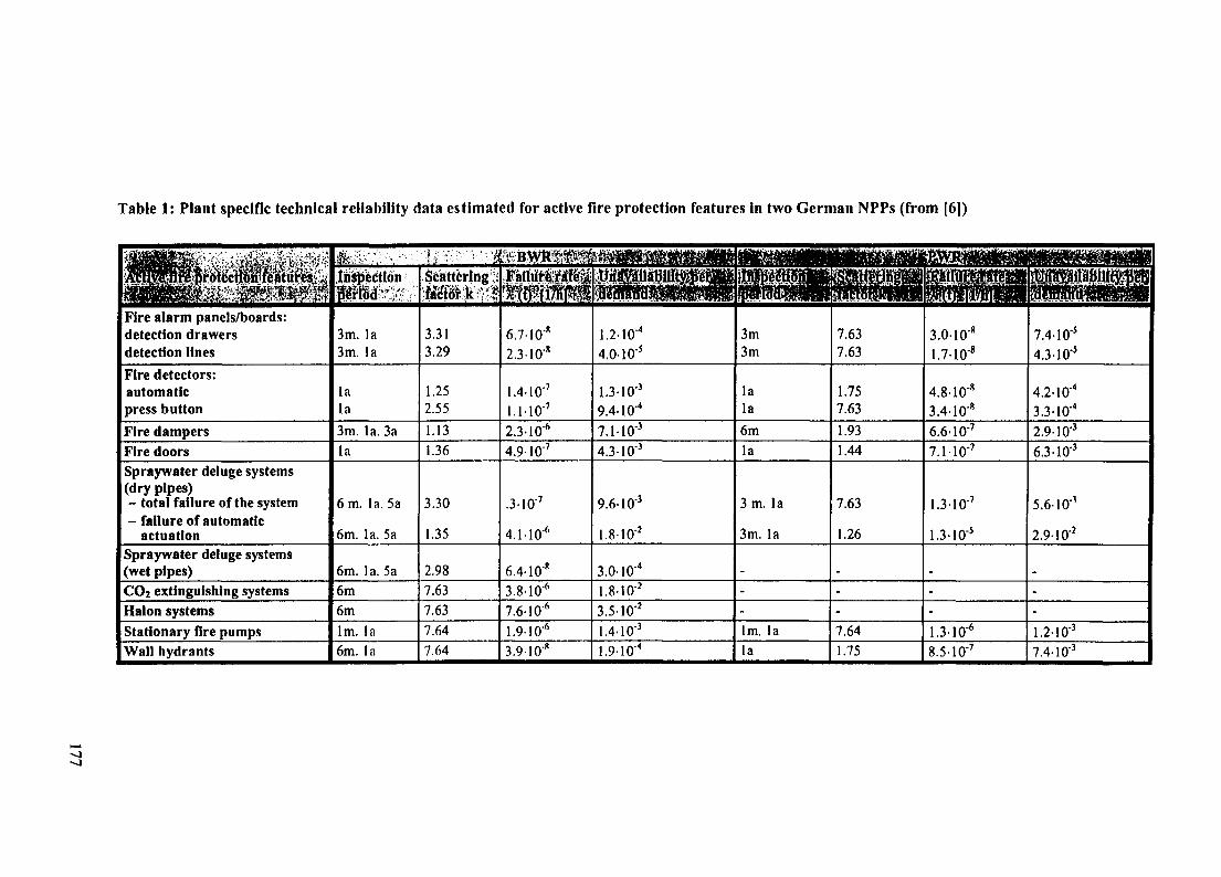
Table 1: Plant specific technical reliability data estimated for active fire protection features in two German NPPs (from [6])
Fire alarm panels/boards:detection drawersdetection lines
Fire detectors:automaticpress button
Fire dampers
Fire doors
Spraywater deluge systems(dry pipes)- total failure of the system- failure of automatic
actuationSpraywater deluge systems(wet pipes)
CO2 extinguishing systems
Halon systems
Stationary fire pumps
Wall hydrants
Inspectioniffrffid' '7
3m. la3m. la
lala
3m. la. 3a
la
6 m. la. 5a
6m. la. 5a
6m. la. 5a
6m
6mlm. la
6m. la
! ' $Scattering _.fMdrk '•'*
3.313.29
1.252.55
1.13
1.36
3.30
1.35
2.98
7.63
7.63
7.64
7.64
A ' - B V V f t ' ' ^Fafltlre^ale^
6.710"
2.310"8
1.4-10'7
1.110"7
2.310"6
4.9I0"7
.3-10"7
4.110"6
6.4-10""
J5.81O"6
7.6-106
1.9-10'*
3.9-10"8
•pij^iaBillWPe^^
1.2-10"4
4.0-10"'
1.3-10"3
9.4-10"4
7.110"3
4.3-10"3
9.6-10"3
1.8-10"2
3.010"4
1.8-1O"2
3.510"2
1.4-10"3
1.910"4
3m3m
lala
6mla
3 m. la
3m. la
_
-
-
lm. la
la
7.637.63
1.757.63
1.93
1.44
7.63
1.26
_
-
-
7.64
1.75
3.0-10"8
1.7-10"
4.8-10"8
3.4-10""
6.6-10"7
7.11O"7
1.310"7
1.3-10"'
-
-
1.310"6
8.51O"7
telaiiMfe^^SLv]
7.410"'
4.3 10"'
4.2-10"4
3.3-10"4
2.9-10"3
6.3-10"3
5.6-10"3
2.910"2
-
-
1.2-10"3
7.4-10'3

00
Table 2: Comparison of the generic reliability data recently estimated for active fire protection features in German nuclear power plantswith internationally available data
Fire alarm panels/boards:- detection drawers- detection lines
Automatic fire detectorsPress button detectorsFire dampersSmoke extraction dampersFire doorsCO2-SystemsHalon systemsSpraywater deluge systems(dry pipes):-total failure of the
system- failure of automatic
actuationSpraywater deluge systems(wet pipes)
Unavailability perdemand estimated for
German referenceplants
BWR
1.17E-04'3.98E-051
1.27E-031
9.43E-041
6.65E-031
1.55E-021
4.25E-031
1.81E-02'3.5OE-O21
9.90E-041
1.78E-02'
3.15E-041
PWR
7.36E-051
4.29E-051
4.22E-041
3.31E-041
2.90E-031
3.26E-031
6.25E-031
3.23E-041
2.93E-O2'
[7|
9.00E-02'
2.00E-031
6.30E-031
[81 I [91 | [10|
5
1.42E-011
5.36E-021
3.80E-02'
2.64E-021
1.16E-012.00E-014.90E-02
4.00E-02
B B M H H H H H I H H H1 [HI [121 1 [131 1 [141
5.90E-02
2
4.00E-026.00E-02
6.00E-031
7.00E-026.00E-024.00E-02 7.00E-02
isfbn-huclearGtrmii
W
4.00E-031
6.50E-02
[16]
<3.00E-01
[Industry
[171
7.90E-021
8.00E-021
'= Technical failures per demand2= 8.60E-02 - 2.40E-01 per demand depending on detector type

As a first result the unavailabilities of most of the fire protection measures analysed actually werelower than those gained from former analyses. For some specific measures the unavailabilities werehigher. The reason for the deviations should result from more realistic assumptions for the actualinvestigations on the one hand and from backfitting actions taken as a result of the former analyses inthe reference plants.
As another result of the overall analysis differences were found concerning the reliability of fireprotection measures between the nuclear and the non-nuclear field. In general, the technical reliabilitywas higher for those measures installed in nuclear power plants. These deviations may result frommore frequent and detailed inservice inspections for the equipment in nuclear installations with ahighly sophisticated quality assurance and maintenance program as well as from the stronglyregulated qualification programmes for the NPP personnel.
4 CONCLUSIONS
The potential of internal fires to simultaneously damage systems and/or components of redundantsafety relevant equipment requires that the current fire protection level of operating NPPs is analysed.In this process, especially those NPPs have to be assessed carefully which have been designed andbuilt to earlier standards taking into account the already implemented fire protection improvements.
The review of the current state of fire protection measures and their reliability is also part of theperiodic safety reviews which have already been performed for more than half of the operating NPPsin Germany. In the past, these reviews were mainly focusing on deterministic investigations.
However, the recently published regulatory guidance for performing periodic safety reviews,developed by the utilities on a voluntary basis and reviewed by the supervising authorities and theirexperts also recommend a fire PSA as an additional tool to the deterministic analyses. Theseprocedures require appropriate methods, models and data.
In particular, preparation of the necessary data is a major prerequisite of a risk based fire safetyassessment. Therefore, a separate chapter in the PSA document on data presently available inGermany [3] provides material based on national as well as international, mainly US, data. In thisdocument, the recently determined data on the technical reliability of active fire protection measureshave been included to provide a broader data base although the use of plant specific data is alwayspreferable.
However, it should be underlined that the necessary data base still has to be improved and to beexpanded for several fire protection features. Moreover, the influence of human actions is to be takencarefully in consideration. In particular for German NPPs, the use of US data for the fire occurrencefrequencies is insufficient due to the consequential conservative assumptions just at the starting pointof the quantitative calculations; on the other hand, the presently available German data do not allow toprovide verified data.
REFERENCES
[1] BUNDESMINISTERUM FUR UMWELT, NATURSCHUTZ UND REAKTOR-SICHERHEIT: Periodische SicherheitsuberprQfung fur Kernkraftwerke - LeitfadenProbabilistische Sicherheitsanalyse, Dezember 1996, Bundesanzeiger, in press, 1997
[2] FACHARBEITSKREIS PROBABILISTISCHE SICHERHEITSANALYSE FURKERNKRAFTWERKE: Methoden zur probabilistischen Sicherheitsanalyse furKemkraftwerke, Dezember 1996; BfS-KT-16/97, 1997
[3] FACHARBEITSKREIS PROBABILISTISCHE SICHERHEITSANALYSE FURKERNKRAFTWERKE: Daten zur Quantifizierung von Ereignisablaufdiagrammen undFehlerbaumen, April 1997, BfS-KT-18/97, 1997
179

[4] GESELLSCHAFT FUR REAKTORSICHERHEIT (GRS) MBH: Optimierung vonBrandschutzmaBnahmen in Kernkraftwerken, GRS-62, ISBN 3-923875- 10-x,September 1985
[5] MULLER, K., MAX, U., ROWEKAMP, M.,: Large Scale Fire Experiments in an oldGerrmin Nuclear Power Plant - An Attempt for a Higher Fire Safety Level;Fire&Safety '94, Nuclear Engineering International, Status Meetings Limited, ISBN0617005583, 1994
[6] ROWEKAMP,M., RIEKERT, T., SEHRBROCK, H.: Ermittlung vonZuverlassigkeitskenngroBen fur Brandschutzeinrichtungen in deutschenKernkraftwerken; GRS-A-2456, Rev. 1, March 1997, BMU-Schriftenreihe BMU-1997-486 in press, 1997
[7] GALUCCI, R: A Methodology for Evaluating the Probability for Fire Loss of NuclearPower Plant Safety Functions, PhD Dissertation, Rennsselaer Polytechnic Institute, Troy,NY, May 1980
[8] LEVINSON, S., YEATER, M.: Methodology to Evaluate the Effectivness of Fire
Protection Systems at Nuclear Power Plants, Nuclear Engineering and Design, 1983
[9] NORTHEAST UTILITIES: Millstone 3 PRA, Appendix 2-K, 1983
[ 10] TAIWAN POWER COMPANY: Maanshan Fire PRA, Appendix D, 1987
[11] PARKINSON, B: SAIC Senior Staff Scientist: Letter to J. Lambright, 1988
[12] GUYMER, P., PARRY, G.W.: Use of Probabilistic Methods in Fire Hazard Analysis,USA. IAEA-SM, 305/1, February 1989
[ 13] BOHN, M. P., LAMBRIGHT, J. A.: Procedures for the External Event Core DamageFrequency Analyses for NUREG-1150, Sandia National Laboratories, Albuquerque, NM,SAND88-3102, NUREG/CR-4840, November 1990
[14] GESELLSCHAFT FUR REAKTORSICHERHEIT: Deutsche Risikostude Phase B,Verlag TUV Rheinland e.V., ISBN 3-88585-809-6, 1990
[ 15] GESELLSCHAFT FUR REAKTORSICHERHEIT (GRS) MBH: AbschluBbericht zurStudie Optimierung von BrandschutzmaBnahmen in Kemkraftwerken, Fachband 1:Theoretische Grundlagenuntersuchungen, GRS-A-1066/1, Koln, September 1985
[ 16] BACKHAUS, W.-J., BRENIG, H.-W.: Mangel an Feuerschutzabschlussen und ihrEinfluB auf die Zuverlassigkeit baulicher Trennungen, Gerling Institut ProSchadensforschung, Schadensverhiitung und Sicherheitstechnik GmbH, BereichBrandschutz/ Sicherheitstechnik, Koln 1991
[17] VERB AND DER SCHADENSVERSICHERER E.V.: Versagen von Brandmeldeanlagenund Loscheinrichtungen, Ausziige aus diversen VdS-Jahresberichten 1990-1995, Koln
180
IAEA-SM-345/6
ESTIMATION OF FIRE FREQUENCYFROM PWR OPERATING EXPERIENCE
XA9847517R. BERTRAND, F. BONNEVAL, G. BARRACHIN, F. BONINOInstitut de protection et de surete nucleaire,Fontanay-aux-Roses, France
Abstract
In the framework of a fire probabilistic safety assessment (Fire PSA), the French Institute forNuclear Safety and Protection (IPSN) has developed a method for estimating the frequency of fire ina nuclear power plant room. This method is based on the analysis of French Pressurized WaterReactors operating experience. An interesting characteristic of this experience is that the reactorspopulation is homogeneous in terms of design, maintenance and operating procedures.
The method adopted consists in carrying out an in-depth analysis of fire-related incidents. Adatabase has been created including 202 fire events reported in 900 MWe and 1300 MWe reactorsfrom the start of their commercial operation up to the first of March 1994, which represents acumulated service life of 508 reactor-years. For each reported fire, several data were recorded amongwhich :
- the operating state of the reactor in the stage preceding the fire,- the building in which the fire broke out,- the piece of equipment or the human intervention which caused the fire.
Operating experience shows that most fires are initiated by electrical problems (short-circuits,arcing, faulty contacts, etc..) and that human intervention also plays an important role (grinding,cutting, welding, cleaning, etc..)
A list of equipment and of human interventions which proved to be possible fire sources wastherefore drawn up. The items of this list were distributed in 19 reference groups defined by takinginto account the nature of the potential ignition source (transformers, electrical cabinets, pumps, fans,etc .) . The fire frequency assigned to each reference group was figured out using the operatingexperience informations of the database.
The fire frequency in a room is considered to be made out of two contributions : one due toequipment which is proportional to the number of pieces of equipment from each reference groupcontained in the room, and a second one which is due to human interventions and assumed to beuniform throughout the reactor. Formulas to assess the fire frequencies in a room, the reactor being ina shutdown state or at power, are then proposed.
To conclude, in the light of initial applications, it appears that the method developed by IPSN iseasy to use. Based mainly on the use of French operating experience, which represents a large numberof reactor years, it guarantees with an adequate level of confidence that the data obtained will berepresentative. One original feature of this method is that it takes into account fires breaking outbecause of human intervention and that it can be applied to power reactors in operation or inshutdown conditions.
1. INTRODUCTION
The French Institute for Nuclear Safety and Protection is performing a fire-probabilisticsafety assessment (Fire PSA). In the framework of this study, a method for estimating thefrequency of a fire in a given reactor room has been developed. This method is based on thefire related experience gained with the 508,2 reactor-years of operation in the French PWRs.
181
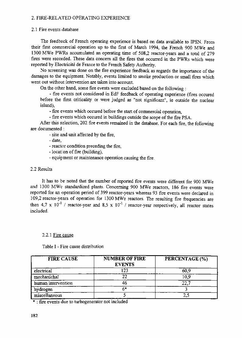
2. FIRE-RELATED OPERATING EXPERIENCE
2.1 Fire events database
The feedback of French operating experience is based on data available to IPSN. Fromtheir first commercial operation up to the first of March 1994, the French 900 MWe and1300 MWe PWRs accumulated an operating time of 508,2 reactor-years and a total of 279fires were recorded. These data concern all the fires that occurred in the PWRs which werereported by Electricite de France to the French Safety Authority.
No screening was done on the fire experience feedback as regards the importance of thedamages to the equipment. Notably, events limited to smoke production or small fires whichwent out without intervention are taken into account.
On the other hand, some fire events were excluded based on the following :- fire events not considered in EdF feedback of operating experience (fires occured
before the first criticality or were judged as "not significant", ie outside the nuclearisland),
- fire events which occured before the start of commercial operation,- fire events which occured in buildings outside the scope of the fire PSA.
After this selection, 202 fire events remained in the database. For each fire, the followingare documented :
- site and unit affected by the fire,- date,- reactor condition preceding the fire,- location of fire (building),- equipment or maintenance operation causing the fire.
2.2 Results
It has to be noted that the number of reported fire events were different for 900 MWeand 1300 MWe standardized plants. Concerning 900 MWe reactors, 186 fire events werereported for an operation period of 399 reactor-years whereas 93 fire events were declared in109,2 reactor-years of operation for 1300 MWe reactors. The resulting fire frequencies arethen 4,7 x 10"1 / reactor-year and 8,5 x 10'1 / reactor-year respectively, all reactor statesincluded.
2.2.1 Fire cause
Table I - F'ire cause distribution
FIRE CAUSE
electricalmechanichalhuman interventionhydrogenmiscellaneous
NUMBER OF FIREEVENTS
12322466*5
PERCENTAGE (%)
60,910,922,7
32,5
* : fire events due to turbogenerator not included
182
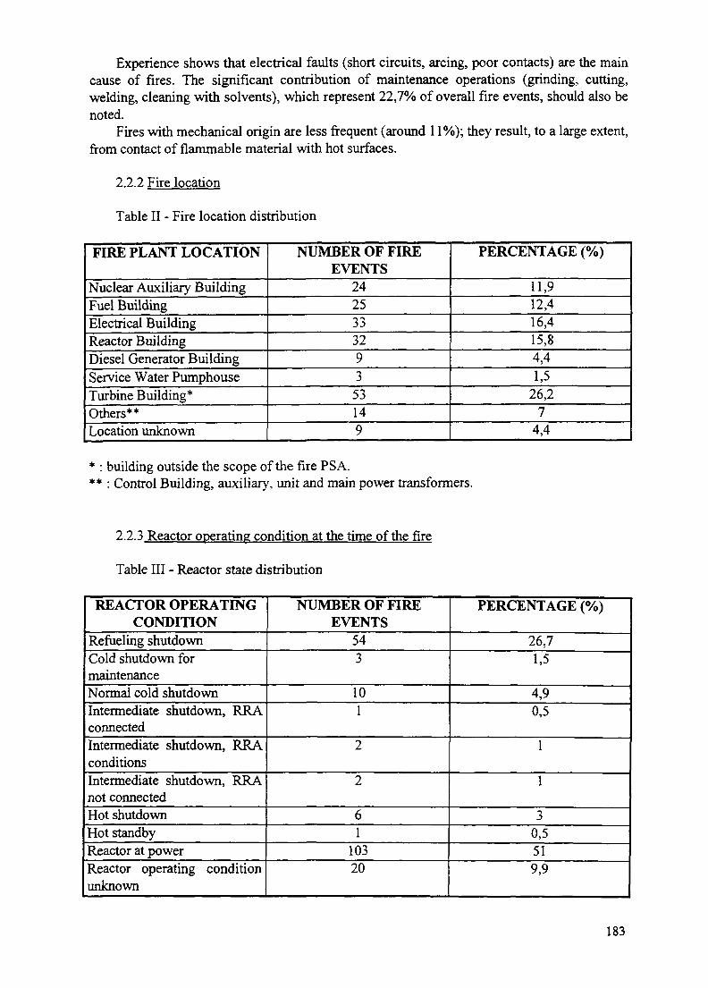
Experience shows that electrical faults (short circuits, arcing, poor contacts) are the maincause of fires. The significant contribution of maintenance operations (grinding, cutting,welding, cleaning with solvents), which represent 22,7% of overall fire events, should also benoted.
Fires with mechanical origin are less frequent (around 11%); they result, to a large extent,from contact of flammable material with hot surfaces.
2.2.2 Fire location
Table II - Fire location distribution
FIRE PLANT LOCATION
Nuclear Auxiliary BuildingFuel BuildingElectrical BuildingReactor BuildingDiesel Generator BuildingService Water PumphouseTurbine Building*Others**Location unknown
NUMBER OF FIREEVENTS
242533329353149
PERCENTAGE (%)
11,912,416,415,84,41,5
26,27
4,4
* : building outside the scope of the fire PSA.** : Control Building, auxiliary, unit and main power transformers.
2.2.3 Reactor operating condition at the time of the fire
Table III - Reactor state distribution
REACTOR OPERATINGCONDITION
Refueling shutdownCold shutdown formaintenanceNormal cold shutdownIntermediate shutdown, RRAconnectedIntermediate shutdown, RRAconditionsIntermediate shutdown, RRAnot connectedHot shutdownHot standbyReactor at powerReactor operating conditionunknown
NUMBER OF FIREEVENTS
543
101
2
2
61
10320
PERCENTAGE (%)
26,71,5
4,90,5
1
1
30,5519,9
183
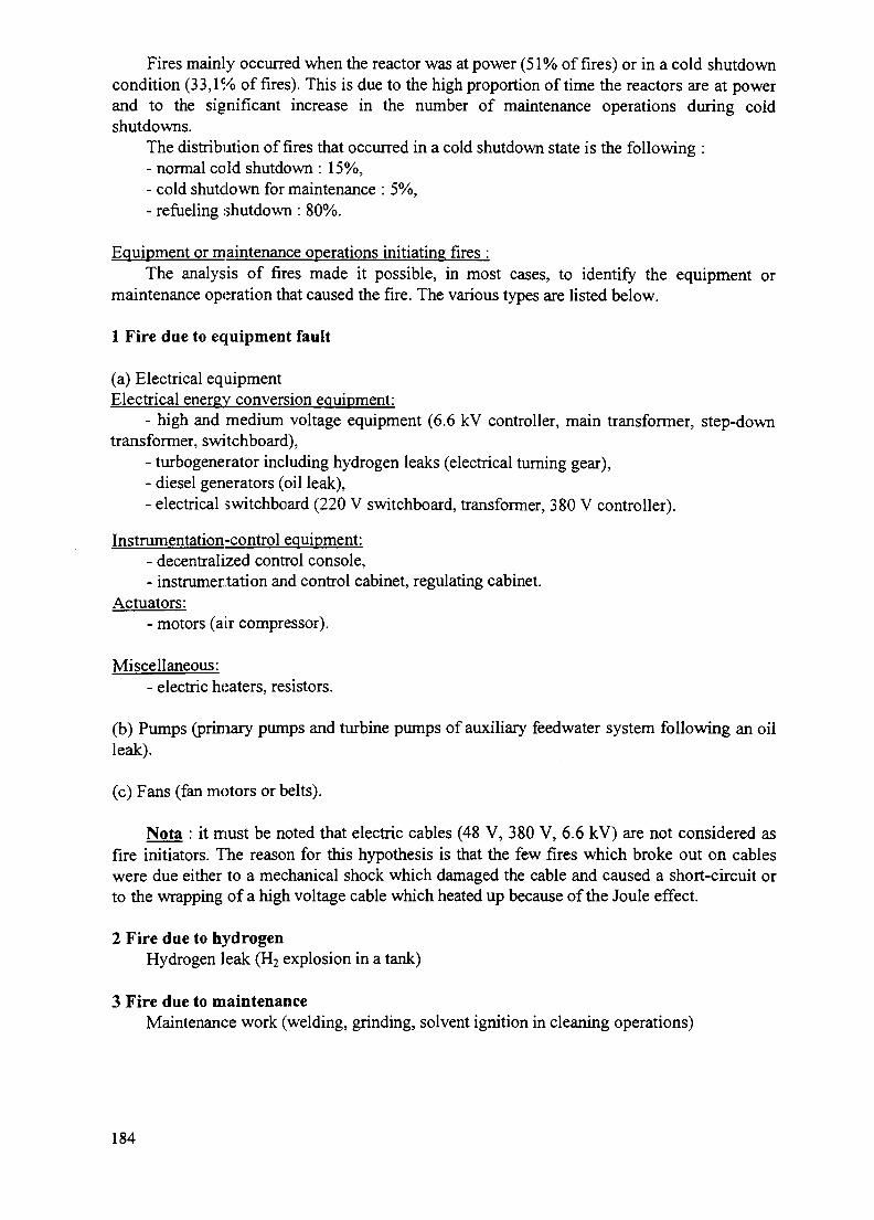
Fires mainly occurred when the reactor was at power (51% of fires) or in a cold shutdowncondition (33,1% of fires). This is due to the high proportion of time the reactors are at powerand to the significant increase in the number of maintenance operations during coldshutdowns.
The distribution of fires that occurred in a cold shutdown state is the following :- normal cold shutdown : 15%,- cold shutdown for maintenance : 5%,- refueling shutdown : 80%.
Equipment or maintenance operations initiating fires :The analysis of fires made it possible, in most cases, to identify the equipment or
maintenance operation that caused the fire. The various types are listed below.
1 Fire due to equipment fault
(a) Electrical equipmentElectrical energy conversion equipment:
- high and medium voltage equipment (6.6 kV controller, main transformer, step-downtransformer, switchboard),
- turbogenerator including hydrogen leaks (electrical turning gear),- diesel generators (oil leak),- electrical switchboard (220 V switchboard, transformer, 380 V controller).
Instrumentation-control equipment:- decentralized control console,- instrumentation and control cabinet, regulating cabinet.
Actuators:- motors (air compressor).
Miscellaneous:- electric heaters, resistors.
(b) Pumps (primary pumps and turbine pumps of auxiliary feedwater system following an oilleak).
(c) Fans (fan motors or belts).
Nota : it must be noted that electric cables (48 V, 380 V, 6.6 kV) are not considered asfire initiators. 7"he reason for this hypothesis is that the few fires which broke out on cableswere due either to a mechanical shock which damaged the cable and caused a short-circuit orto the wrapping of a high voltage cable which heated up because of the Joule effect.
2 Fire due to hydrogenHydrogen leak (H2 explosion in a tank)
3 Fire due to maintenanceMaintenance work (welding, grinding, solvent ignition in cleaning operations)
184
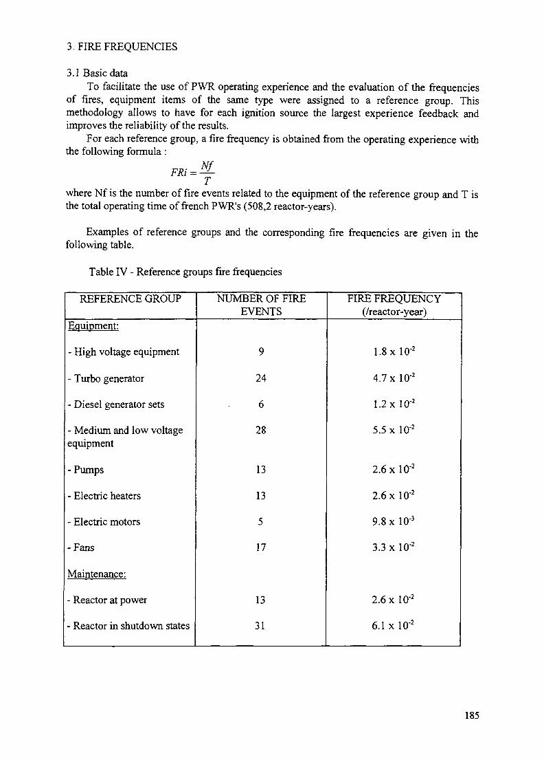
3. FIRE FREQUENCIES
3.1 Basic dataTo facilitate the use of PWR operating experience and the evaluation of the frequencies
of fires, equipment items of the same type were assigned to a reference group. Thismethodology allows to have for each ignition source the largest experience feedback andimproves the reliability of the results.
For each reference group, a fire frequency is obtained from the operating experience withthe following formula:
Twhere Nf is the number of fire events related to the equipment of the reference group and T isthe total operating time of french PWR's (508,2 reactor-years).
Examples of reference groups and the corresponding fire frequencies are given in thefollowing table.
Table IV - Reference groups fire frequencies
REFERENCE GROUP
Equipment:
- High voltage equipment
- Turbo generator
- Diesel generator sets
- Medium and low voltageequipment
-Pumps
- Electric heaters
- Electric motors
-Fans
Maintenance:
- Reactor at power
- Reactor in shutdown states
NUMBER OF FIREEVENTS
9
24
6
28
13
13
5
17
13
31
FIRE FREQUENCY(/reactor-year)
1.8 xlO"2
4.7 x 10"2
1.2 x lO"2
5.5 x 10²
2.6 x 10"2
2.6 xlO"2
9.8 x 10"3
3.3 xlO"2
2.6 xlO"2
6.1 x 10²
185

3.2 Fire frequency estimation method
Reactor at power
The estimation of the fire frequency in a room has to take into account two contributions: one due to equipment, the other due to maintenance operations.
EquipmentFor each reference group, it is considered that the frequency of a fire due to the
equipment is proportional to the number of equipment items located in the room.For each reference group, the following data is then needed :- the fire frequency of the reference group (FRi),- the number of equipment items of the reference group in the room (Ni),- the number of equipment items of the reference group in the plant (NTi).
The contribution of this reference group to the fire frequency in the room is then :
NTi
It must be noted that this method only concerns the buildings where a fire could threatenthe safety of the plant. For a standard french 900 MWe PWR, it represents 822 rooms.
Knowing the contribution of each reference group i, the fire frequency in a room due toits equipment (Fl) is obtained by summing the contributions Fi of the different groups :
Fl = IFii
Maintenance operationsAs the number of maintenance operations in a room is not known, it is considered, as a
first approximation, that their contribution is uniform throughout the installation. If MP is thereference frequency, when the plant is at power, the contribution of maintenance operations tothe fire frequency in a room is :
FlNL
where NL is the total number of rooms in the installation where maintenance operations wereperformed. (NL = 664 for a standard french 900 MWe PWR, the rooms of the reactor buildingbeing excluded)
Frequency of a fireThe fire frequency in a room is then obtained by summing the contributions due to
equipment and to maintenance operations :
NL
186

3.3 Results
The method for estimating the frequency of a fire was applied to unit 1 of the Blayaispower station (900 MWe PWR) for all the rooms containing safety-related equipment.Implementing this method required to create an equipment database, allowing the location ofeach equipment item for the reactor. This database was established both from existingcomputer files (electrical cable listings and maintenance operation data used by the operator)and from data obtained by on-site visits. So it was possible to evaluate, for each referencegroup, the number of equipment items in each room and in all the plant. The approach wascompletely computerized using a database management software program which made it easyto calculate the frequency and to provide for possible updating.
For the Blayais station, with the reactor at power, the order of magnitude of firesfrequencies obtained varies from 10"5 to 10"2/reactor year, depending on the room content.
The distribution of rooms as a function of the different frequency ranges is shown in thefollowing table :
Table V - Rooms distribution according to frequency range
FREQUENCY-RANGE(/reactor-year)
i(rs<f<i(r4
l(T4<f< 1(T3
icr3<f< iff2
NUMBER OF ROOMS
166
106
40
It must be noted that the total number of rooms is 312 which corresponds to the roomswhere a fire could cause the loss of cables or equipment necessary to the reactor operation.
4. CONCLUSION
The analysis of fire-related operating experience provided information for carrying outthe fire probability study. It is actually possible to identify the equipment items andmaintenance operations which constitute the principal ignition sources for PWRs. It alsoallowed to attribute a fire frequency to each ignition source. These informations were used todevelop the method for estimating the fire frequency for a room. This method allows to obtainreliable data due both to the homogeneous design of the French PWRs and to the considerableoperating experience gained from more than 500 reactor-years. The application of this methodto unit 1 of the Blayais power station shows that the approach developed by IPSN is easy toimplement. The fire frequency for each room will be used to select the critical areas (roomswhere the contribution of fires to the probability of core meltdown is not negligible).
Moreover, equipment or materials with an appreciable energy content, such as flammablefluids, near an ignition source constitute potential fires that should be studied as initiators offire scenarios. The data acquired allow to estimate frequencies for these points and will beused to quantify the probabilities of fire scenarios liable to induce core meltdown.
187

BIBLIOGRAPHY
Rapport DES/SERS n°29 - septembre 1996 - Frequence d'incendie - G. BARRACHIN.
Note EDF/SEPTEN ENS FC/94 183 indice A du 23 mars 1995 - Base de donnees desfeux intervenus dans les centrales nucleaires REP francaises - M. GUERCHOUX.
188

IAEA -SM-345/5CRITERIA FOR CLASSIFICATION AND REPORTINGOF FIRE INCIDENCES IN NUCLEAR POWER PLANTS HIM mini nil mil Hill Mil IIOF INDIA Illlinillllllllllllll
XA9847518R.K. KAPOORDirectorate of health, Safety, Environment
and Public Awareness,Nuclear Power Corporation of India Limited,Anushaktinager, Mumbai, India
Abstract
It is important that all fires in and around fire effective neighbourhood of Nuclear Power Plant (NPP)
should be promptly reported (Reportable fires) and investigated. However, the depth of investigation
and the range of authorities to whom the individual fire incidence need to be reported depends upon
the severity of fire. In case of conventional non-chemical industries, the severity of fire depends
mainly on the extent of loss caused by fire on property and the burn injury to persons. In case of NPP,
two additional losses viz., release of radioactivity to working/public environment and the risk to
safety related systems of NPP due to fire assume greater importance. This paper describes the criteria
used in NPPs of India for classification of reportable fire incidences into four categories, viz.,
Insignificant, small, medium and large fires. It also gives the level of investigation depending upon
the severity of fire. The fire classification scheme is explained in this paper with the help of worked
out examples and two incidences of fire in Indian NPPs.
1. RELEVANCE OF RECORDS OF FIRE INCIDENCES AND ITS ANALYSIS
A systematic record of fire incidences is important for deciding the extent of upgradation
needed for fire protection and also as an input data for carrying out Probablistic Safety
Analysis of Nuclear Power Plant (NPP). Hence, it becomes essential that all fire
incidences in and around fire effective neighbourhood of NPP's should be reported,
recorded and investigated. Since fire destroys many of the evidences, estimating the root
causes of fire generally becomes a time consuming activity. Further, in view of the
impact a fire has on safety of NPP, the information on fire incidences is required to be
given to different levels of management and regulators. This results in collection of large
189

number of data (as minor fires of no significance also get reported) of fire incidences and
investigation of these by different levels of management and regulators. Hence, a need
has been felt to develop a criteria for classification of fire incidences, the levels of
management up to which fire incidence should be reported, and to decide about the level
of experts required to investigate the root causes of the fire incidence in NPPs.
2. CLASSIFICATION OF FIRE INCIDENCES
A criteria was developed to be used in Nuclear Power Plants (NPP) of India for
classification of fire incidences and for its reporting. The aim in developing this criteria
was that all fires in and around the fire effective neighbourhood of NPP should be
reported and investigated. The level of investigation and reporting depends upon the
severity of fire as defined by its class. Any other fire outside the above referred domain
is called as non-reportable fire. Such non reportable fires are mainly due to burning of
dry grass and are categorized as grass fires.
The reportabie fires are classified into the following four categories based on the extent
of damages and risks involved.
a) Insignificant fires
b) Small fires
c) Medium fires
d) Large fires
The following types of damages and importance of safety systems are considered for
categorizing the fires in the above referred classes.
Amount of financial loss
Burn injury to persons
Release of radioactivity to working/public environment
Risk to the safety related systems.
190

The classification of fires based on type of loss/location area is given in the table I. Each
fire taking place within the plant boundary and other plant related areas (such as stores,
water intake system, waste management facilities etc.) except residential colony is
analysed for identifying its class using this table.
TABLE I. CLASSIFICATION OF FIRES
Tyi>e of loss/Location
Financial loss due to fire
Extent of bum injury
Release of
activity due
to fire
L
0
C
A
T
I
O
N
Non-Safetyrelatedarea
Safety
related
areas
Plantworkingenvironment
Publicenvironment
SafetyequipmentNotinvolved infire
Safetyequipmentinvolved infire
Class of fire
Insignificant< Rs. 10,000/-
Noburninjury
Withinnormalpermissiblelimit
Withinnormalpermissiblelimit
Fire gotextinguishedby itself or byusing portablefireextinguisher
Fire gotextinguishedby itself.
SmallBetweenRs. 10,000/- andRs. 5 lakhs/-
Man-hour ] < 8lost due to ] Manbum injury] days
Between 1 to 10times the limit
Between 1 to 2times the limit
Fire gotextinguishedonly after use offixed suppressionsystem or firetender.
Fire gotextinguished byusing portablefire cxtinfjUisiicrs
Fire got
itself.
MediumBetweenRs. 5.1 lakhs andRs. 1 crore
Man-hour lost] > 8due to bum ] Maninjury ]daysBut not fatalBetween 1 to 100 timesthe limit
Between 2 to 10 times thelimit
Fire got extinguished byusing fixed suppressionsystem or by using firetender.
Fire got extinguished byusing portable fireextinguisher
Large
>Rs. 1crore
Bum injuryleading tofatality
> 100 timesthe limit
> 10 timesthe limit
Fire gotextinguishedby usingfixedsuppressionsystem or byusing firetender.
• Note: 1. Rs. Rupee, an Indian currency2. 1 Lakh = 0.1 million3. 1 Crore = 10 million
191

TABLE Il-a. EXAMPLES FOR CLASSIFICATION OF FIREDATA ON FIRE
Lx.No.
1
1
3
4
b
6
/
8
10
11
12
13
14
15
16
1/
18
Financialloss
(Rupees)
Rs. 1 lakh
Rs. 2crores
NIL
NIL
NIL
NIL
NIL
NIL
Rs. 5Crores
Rs. 2 lakh
NIL
10 lakhs
50 lakhs
80 lakhs
10 lakhs
8 lakhs
NIL
1 lakh
Burn Injury
(Man dayslost)
7 days
No bum injury
Fatal
No bum injury
No bum injury
No bum injury
No bum injury
No bum injury
Fatal
No bum injury
No bum injury
100 days
20 days
200 days
25 days
Fatal
No bum injury
Fatal
Activity released(limit)
Plant
5 times
NIL
NIL
2000times
NIL
NIL
NIL
NIL
5000times
1000times
20 times
40 times
100 times
15 times
NIL
NIL
12 times
NIL
Public
< limit
NIL
NIL
< limit
NIL
NIL
NIL
NIL
100times
3 times
NIL
NIL
15 times
1.5timesNIL
NIL
2 times
NIL
Location
Safety related area(Safety Equipment)involved
Yes
Yes
Yes
Yes
Yes
Yes
Yes
Yes
notinvolved
Yes
Yes
Yes
Non Safetyrelated area
Yes
Yes
Yes
Yes
Yes
Yes
Yes
Extinguishing Style
portable extinguisher
fire hydrant
extinguished itself
portable extinguisher
extinguished itself
extinguished itself
portable extinguisher
fire tender
fire tender
fire tender
portable extinguisher
fixed fire suppressionsystem
fire tender
fire tender
fire tender
fire tender
fire tender
fire tender
1 US Dollar = 37 Rupees Lakh = 0.1 million Crore= 10 million
192

TABLE Il-b. EXAMPLES FOR CLASSIFICATION OF FIREASSESSED CLASS OF FIRE
Ex.NO.
1
2
3
4
5
6
7
8
9
10
11
12
13
14
15
16
17
18
Finance
Small
Large
Insignificant
Insignificant
Insignificant
Insignificant
Insignificant
Insignificant
Large
Small
Insignificant
Medium
Medium
Medium
Medium
Medium
Insignificant
Small
Bum Injury
Small
Insignificant
Large
Insignificant
Insignificant
Insignificant
Insignificant
Insignificant
Large
Insignificant
Insignificant
Medium
Medium
Medium
Medium
Large
Insignificant
Large
Activity
PlantSmall
Insignificant
Insignificant
Large
Insignificant
Insignificant
Insignificant
Insignificant
Large
Large
Medium
Medium
Medium
Medium
Insignificant
Insignificant
Medium
Insignificant
PublicInsignificant
Insignificant
Insignificant
Insignificant
Insignificant
Insignificant
Insignificant
Insignificant
Large
Medium
Insignificant
Insignificant
Large
Small
Insignificant
Insignificant
Small
Insignificant
Location
Insignificant
Small
Insignificant
Insignificant
Insignificant
Small
Medium
Large
Large
Large
Medium
Medium
Large
Large
Large
Small
Small
Small
Final classof fire
Small
Large
Large
Large
Insignificant
Small
Medium
Large
Large
Large
Medium
Medium
Large
Large
Large
Large
Medium
Nonreportable
Remarks
Grass fire in storeyard
Grass fire inwaste burial
ground
**
** Grass fire in colony contract labour died. The worth destroyed is Rs.1 lakh, this is classified asnon-reportable because it is away from plant premises
193

3. ASSIGNING CLASS' TO FIRE INCIDENCES
The classification of fire is to be done based on all the types of damages/location using
Table 1. Which ever assessment gives the highest severity of fire, the fire incidence in
analysis is assigned that severe class. To facilitate users for assigning 'class' of fire to fire
incidences, illustrative (hypothetical) cases of fire are explained by worked out examples
in Tables II - a and II- b. The data on these fire incidences is given in Table Il-a and
assessment of "class' for the incidence based on the extent of financial loss/burn
injury/activity release/location is given in table II -b. It can be seen from these tables that
if any fire incidence involved safety related equipment, the fire incidence falls in higher
severity class. A typical example is no.8, which gave a class as 'Insignificant' based on
financial loss, bum injury, activity release but classed as 'Large' since the fire involved
safety related equipment and could only be extinguished using fire tender. Similarly,
higher class is assigned to fire if activity is released (example no. 10). A typical case of
grass fire is given in example No. 16 wherein fire has been assigned a class 'Large' as it
resulted in a fatality. Whereas in another case (example no. 17) of grass fire, though no
financial loss/no burn injury/non involvement of safety related equipment occurred, but
due to activity release it is assigned higher class.
4. REPORTING AND ANALYSIS OF FIRE INCIDENCES
The reporting and analysis criteria of fires is given in Table m . There is a local plant
fire safety committee at each of the NPP, which investigates all the insignificant and
small fires including grass fires and these are not reported to Corporate office and to the
regulatory authorities. Special fire investigation committee consisting of members from
that NPP are instituted for investigating each of the medium fires. Members from units
other than the plant are also included in the special fire investigation committee instituted
for investigation of each of the large fires. The fire incidences particularly falling in
194

TABLE III. REPORTING AND ANALYSIS CRITERIA OF FIRES
Nature ofactionReporting to
Investigationby
Grass fires
Local plantManagement
Local fireSafetyCommittee
Tiid ornnennt
Local PlantManagement
Local fire SafetyCommittee
Small
Local PlantManagement
Local fixe SafetyCommittee
Medium
Local PlantManagement
Corporate office
AERB
DAE Apex FireSafetyCommittee
Specialinvestigationcommitteeconsisting ofplant mprmhers:
Large
Local PlantManagement
Corporateoffice
AERB
DAE ApexFire SafetyCommittee
Concernedstatutory body.SpecialinvestigationcommitteeconsiSuiis? OTmembers alsofrom unitsother than theplant.
Note:- 1. AERB - Atomic Energy Regulatory Board
2. DAE - Department of Atomic Energy
medium and large fire categories are also investigated by committee instituted by Atomic
Energy Regulatory Board (AERB). Another higher level committee called Department
of Atomic Energy's (DAE) Apex Fire Safety Committee periodically discusses the fire
incidences and makes appropriate recommendations applicable to the NPPs and to other
plants of DAE to prevent occurrence of similar fire incidences. Each of the medium and
large fires are promptly (within 24 hours) reported to Corporate office and to the
concerned statutory authorities.
5. ANALYSIS OF SOME FIRE INCIDENCES IN INDIA'S NAPP'S
The criteria described in this paper has been put in practise at NPPs of India in 1997, and
no significant fire has occurred as yet during this year. However, two incidences of fire
which occurred in earlier years are described in this section. As yet no fires have
195
occurred in India's NPPs involving burn injuries or release of radioactivity, still some
fires falling in class of'Large' have occurred mainly because it affected the safety related
system and resulted in financial losses.
5.1 Cable fire at RAPS-2
Rajasthan Atomic Power Station Unit-2 (RAPS -2), a 220 Mwe Nuclear Power Station is
located at Rajasthan, India. The incident occurred on 25th July, 1985, when the Station
was operating at 200 Mwe. One primary circulating pump tripped on instantaneous over
current. This was followed by a reactor trip. Several annunciations came in
simultaneously. Attempt was made to restart the pump, (on hindsight this is conjured as
a wrong step). Three more pumps tripped afterwards. Fast cool down of the reactor was
initiated. Entry was made into Boiler room inside Reactor Building. Thick smoke
resulted in extremely poor visibility. The emergency core injection alarm came in
spuriously. Due to this, the shutdown cooling pumps had to be started after jumping the
logic. During design stage no elegant arrangement was made for purging the smoke and
entry without B A set was possible only after about 7 hours. Core cooling was adequately
taken care of and no radiation spread was there. Unit was restarted after 73 days of
repair/modification work.
The classification of this fire incidence of RAPS as per different types of damages is as
follows:
Financial loss -Large fire
Burn Injury - Insignificant fire
Activity release - Insignificant fire
Safety related equipment - Large fire
Final class - Large fire
196
5.2 Narorafire incident
The Narora Atomic Power Station (NAPS) is a twin - unit, (220 Mwe each) PHWR
located in Uttar Pradesh, India. Unit 1&2 of NAPS were commissioned in the year 1989
and 1992 respectively. On March 31, 1993, a fire occurred in the turbine building of
NAPS-1. Failure of turbine blades in the 5th stage of flow path-2 of the LP turbine was
identified as the cause of the incident. This led to failure of the generator hydrogen seals
and the escaping hydrogen got ignited resulting in a large fire. The fire spread to several
power and control cables in the turbine building and caused complete loss of power
supply which lasted for a period of 17 hours. The reactor was immediately tripped and
could be maintained in a safe shut-down state with adequate sub-criticality at all stages
subsequently. Crash cool down of the primary heat transport system was done and
subsequently fire fighting water was injected into the steam generators for maintaining
thermosyphon cooling of the core. The fire was confined within the turbine building.
Control power supply cable trays on the mezzanine floor (106M elevation) got severely
affected by fire. Turbo-generator (TG) support structure and portion of the slab around
TG set suffered damage due to intense heat of fire. Number of window glass panes in
turbine building were found shattered.
Cable fire, lack of proper fire-retarding provisions and inadequacy in fire-barriers
together with insufficient physical separation in redundant safety related cables was
identified as the main cause of the extended station black out and consequent degradation
of several safety systems. However, there was no radiological impact due to the incident,
either on the plant or in the public domain and there was no loss of life or injury to
personnel. The incident was categorised at level-3 on the International Nuclear Event
Scale.
197

The classification of this fire incidence of NAPS as per different types of damages is as
follows:
Financial loss - Large fire
Burn injury - Insignificant fire
Activity release - Insignificant fire
Safety related equipment - Large fire
Final class - Large fire
5.3 Reporting and investigation of RAPS and NAPS fire incidences
Though the present criteria of classification and reporting of fire incidences was not in
practice at the time of these two fire incidences, these were reported and investigated as
per the criteria given in this paper. The fires were treated in 'Large' fires class, reported
immediately to concerned management and regulator. Special committees were
instituted to investigate these incidences.
6. CONCLUDING REMARKS
The criteria given in this paper is basically classifying fires into a very limited number of
categories. On one hand the classification scheme should be simple, at the same time one
should be able to clearly distinguish between fires of different severity. The last
requirement may necessitate even a finer classification among "Large' fires. For
example, the Narora fire case given in this paper is comparatively of higher severity than
that of RAPS cable fire. In case, the fire incidence results in burn injury including
fatalities along with large scale release of radioactivity (as has been the case with
Chernobyl), the severity is infact very high. Apparently, there is a need to further develop
the fire classification criteria and better would be to have an internationally accepted
standard on similar lines as International Nuclear Event Scale (DMES). This could be
considered by IAEA for developing a guide on this subject.
198

IAEA-SM-345/7RISKS OF TURBINE GENERATORSAT VVER-440 NUCLEAR POWER PLANTS
T. VIROLAINEN, J. MARTTILA, H. AULAMO XA9847519Radiation and Nuclear Safety Authority,Helsinki, Finland
Abstract
Many serious fires and incidents have occurred in the turbine halls of nuclear power plants,resulting in serious damage and long shutdown outages. Some of these incidents have endangered thesafe shutdown of the plants because of the location of lack of vital fire protection safety systems. Adetailed analysis is necessary for all those plants that have equipment important for safe shutdownlocated in the turbine hall or its vicinity without strict fire separation by fire rated barriers. A reduc-tion in the fire frequencies of the turbine hall is an additional way of improving safety. This is pos-sible by improving all aspects of turbine generator operation.
1 INTRODUCTION
It was earlier generally assumed that turbine generators are part of an NPP's conventional systems which an
not important to nuclear safety. However, operational experience has indicated that disturbances of turbiru
generator systems often affect overall plant safety. Many disturbances have led to accidents causing extensive
damage in turbine halls and in their vicinity. The worst consequences have been loss of habitability of the
control room, loss of residual heat removal or total loss of electrical power for a longer period.
Operational experience has also shown, that frequencies for events initiating from turbine generators arc
much higher than estimated in the design phase. The most serious consequences of turbine generator failures
seem to be fires, which also have a very high event frequency. Some disturbances and accidents have taken
place in Soviet-designed plants. In VVER-440-plants, turbine generator damage can lead to the loss of the
main feed water, emergency feed water and primary circuit residual heat removal functions because these
systems are located in the turbine hall.
This paper is based on extensive research, the goal of which has been to assess the operational safety of tur-
bine generators at WER-440 plants, especially at Loviisa NPP. In this paper, the operation, monitoring,
testing and inspections of the most significant turbine generator systems have been studied. Taking these
findings into consideration and by using operational data from Loviisa and other power plants, the most sig-
nificant safety issues of the turbine generator systems have been identified. The frequency of initiating events
and their possible consequences have been determined by using operational experience data and relevam
literature.
199

VVER-440 TURBINE HALL FEATURES
2.1 Lay-out considerations
The original VVER-440 PWR plant concept consists typically of two reactors sharing a common turbine hall.
Steam generated by the six steam generators of the one reactor streams to two turbine generators, which are
located axially to ihe control (or intermediate) building. The turbine building is an open hall without any
walls or fire barriers between the turbine generators. The control rooms, relay and switchboard rooms as well
as cable rooms are situated inside the same building complex, in a so-called intermediate (or deaerator)
building.
The load bearing siructures and roof beams of the integrated turbine hall and intermediate building are made
of uninsulated stee! constructions. Thus, severe damage or even collapsing of the structures or roof in a big
turbine hall fire is possible in less than ten minutes, as fire analyses as well as accidents occurred at similarly
constructed Soviet-designed NPPs prove.
Many important components are located in the open space of the turbine hall e.g. the main and auxiliary feec
water pumps, pipelines and valves, power and control cables of these systems as well as condensate pumps.
Furthermore, many cable raceways that serve other safety-related systems are located in the open space of the
turbine hall. According to the original design, none of these systems is protected against fires or collapsing
structures. Fire may also spread to other compartments through inadequately sealed penetrations along the
cable raceways as well as inadequate, open or missing fire doors. In addition, smoke may spread to the inter-
mediate building and possibly jeopardize the habitability of the control rooms.
Loviisa NPP is modified and improved from the original VVER-440 plant concept (see the paper "Safety
improvements at Loviisa NPP to reduce fire risks originating from turbine generators")- The Loviisa reactors
are situated in independent reactor containment buildings and the turbine generators are located in a favour-
able position transversally to the reactor buildings thus reducing the danger of missile ejection from turbine.
Fire protection has been accounted for already in the original design and further significantly improved during
the plant's operation.
2.2 Description of turbine generator systems
This chapter describes mainly the turbine generator systems as constructed at Loviisa NPP. Some systems
differ substantially from other WER-440 plants e.g. hydrogen supply piping, fire valve in the governing oil
line etc. The turbine generators are also protected with local and area sprinkler systems.
The Loviisa turbines comprise of one high pressure (HP) turbine case and two low pressure (LP) cases. After
the HP turbine there are two superheaters next to each other. The generator and turbine are interconnected by
a common shaft. Their speed of rotation is 3000 1/min.
200

Figure 1. Loviisa turbine hall.
The auxiliary of the turbine generators systems are:
turbine:
generator:
lubricating oil system (includes also lifting oil system)
governing and protection oil system
condensing system and ejectors
gland steam system
turbine drain system
excitation system
stator water cooling system
hydrogen cooling system
sealing oil system.
Considering fire risks, the most risk-significant auxiliary systems are oil systems and the hydrogen cooling
system. Lubricating oil is a big fire load (56m3 per turbine generator, corresponding to a thermal power of
190 MW with burn-out of three hours). Hydrogen's fire load is minor, but due to its sensitivity for explosion
the risks are also significant. Other notable fire loads are the lubricating oil of the pumps (for instance the
main feed water pumps) and the electrical components (cables, motors etc.) which are located everywhere in
the turbine hall.
201

1234567
lubricating oilgoverning oiloil flow to upper oil tanksleak and return linebleeder linesea water linelifting oil line
10 _ _ 10
upper oil tanks 2 • 8,5 m3
fire valveimpeller pumpgoverning oil pumpintegrated axial and radial bearingssignal oil to hydraulic speed governorgoverning and protection oil feedingradial bearing
Figure 2.
9101112
•s 13nor 14ig 15
Lubricating system.
high pressure turbinelow pressure turbinesgeneratormain oil tank 56 m3
lifting oil pumps 2 100%main oil pumps 2 • 100 9coil coolers 2 • 100%
2.2.1 Lubricating systems
Lubricating oil to a turbine generator's bearings flows from two upper oil tanks (gravity tanks), which are
situated on the turbine hall's inside wall. Lubricating oil is pumped from the main oil tank into the upper oil
tanks by main oil pumps (fig. 2). The main oil tank is located beside the generator, but on a lower level. The
upper oil tanks are dimensioned so that if the oil flow from the main oil pumps stops, bearings lubrication can
be maintained during turbine generator shut-down.
In shut-down or start-up phase, normal lubrication is insufficient due to low rotation speed. Therefore the
lifting oil system feeds oil to the lower coating of the bearings with a 5,0 MPa pressure for maintaining an oil
film between bearina and shaft babbitt metal surfaces.
2.2.2 Generator sealing oil and hydrogen cooling systems
The Generator rotor is cooled by hydrogen. Hydrogen, the pressure of which is about 0,4 MPa and volume
about 225m3NTP, circulates inside the generator through the air gap and the stator's table packs. The flow is
202
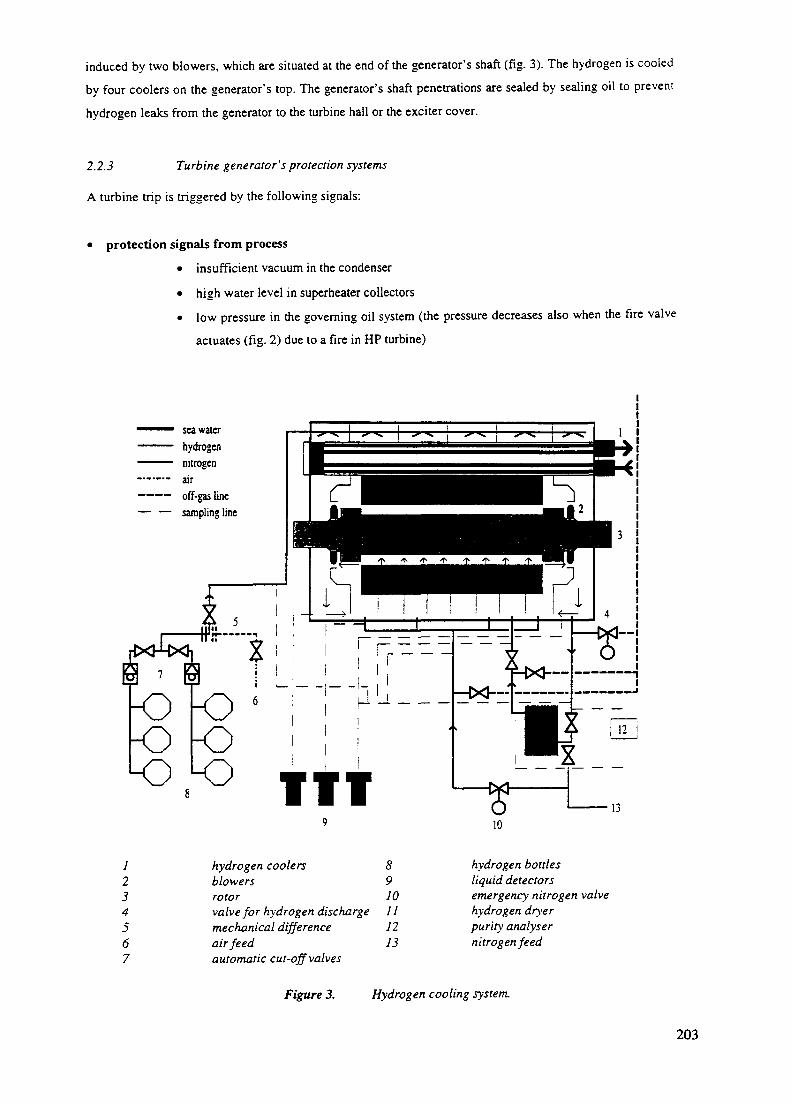
induced by two blowers, which are situated at the end of the generator's shaft (fig. 3). The hydrogen is cooled
by four coolers on the generator's top. The generator's shaft penetrations are sealed by sealing oil to prevent
hydrogen leaks from the generator to the turbine hall or the exciter cover.
2.2.3 Turbine generator's protection systems
A turbine trip is triggered by the following signals:
• protection signals from process
• insufficient vacuum in the condenser
• high water level in superheater collectors
• low pressure in the governing oil system (the pressure decreases also when the fire valve
actuates (fig. 2) due to a fire in HP turbine)
sea waterhydrogennitrogenairoff-gas linesampling line
-o5 ITT
1234567
hydrogen coolersblowersrotorvalve for hydrogen dischargemechanical differenceair feedautomatic cut-off valves
8910111213
hydrogen bottlesliquid detectorsemergency nitrogen valvehydrogen dryerpurity analysernitrogen feed
Figure 3. Hydrogen cooling system.
203

• low steam pressure in HP turbine inlet
• high pressure in HP turbine regulating chamber
• high steam pressure in HP turbine outlet
• high water level in steam generators
• power difference between primary and secondary circuits
• other protection signals
• axial movement of turbine generator shaft
• operation of turbine's mechanical overspeed device
• failure of hydraulic speed governor
• closure of superheater's butterfly valves during power operation
• closure of at least two out of four stop valves
• manual trip from control room
• manual trip locally from turbine
• reactor shutdown
• signal from generator's protections
• signal from transformers' protections.
The majority of the generator protections will also cause a turbine trip signal. In a loss of off-site power
situation the aim is that the unit would remains in the house-load operation mode. Then the 400 kV main
circuit breaker will open due to the operation of generator protections but turbine protection will not get a
signal for turbine Dip.
3 MONITORING, TESTING AND INSPECTIONS OF TURBINE GENERATORS
3.1 Monitoring during power operation
The major monitoiing objects for operational safety are:
• temperature of turbine generator bearing babbitt metal and lubricating oil
• vibrations of re tor and bearings, especially rapid changes in vibration levels
• anomalous values and rapid changes of steam pressure and power output
• cleanliness of generator's carbon brush
• leak tightness of hydrogen and oil systems, the amount and location of the leak
• purity and humidity of hydrogen
• oil pressure in sealing oil system
• liquid leaks into generator.
Many of the measurements mentioned above can be performed by using plain temperature or pressure sen-
sors. More advanced systems have to be utilized when vibration levels, purity or humidity values and gas or
liquid leaks are rated.
204

5. /• •/ Vibration monitoring
Vibration monitoring observes the condition of turbine generators extensively. The Loviisa NPP units have
some differences in monitoring systems. Loviisa-1 bearing vibrations are monitored by speed probes, which
measure horizontal vibrations from all bearings and axial vibration from one bearing. Shaft vibrations arc
monitored by eddy current probes. They give both horizontal and vertical vibration levels which are relativeh
compared to bearing vibrations. The overall level of bearing vibrations is presented on the process computer
display. The time delay between monitoring and display is rather long, about 20 minutes. In-situ values can
only be read from the monitoring system's central unit in the back of the control room. Values from the probe
are also led through the central unit to a condition monitoring system, which gives a report after 20 minutes'
delay.
Loviisa-2 vibration monitoring system sensors are more advanced than those in Loviisa-1. Bearing vibrations
are measured by accelerometers for all bearings in vertical direction and for two bearings in axial direction.
Shaft vibration sensors measure relative values from both sides of turbine cases and generator in horizontal
and vertical directions. Some improvements have been planned for vibration monitoring systems, especially at
Loviisa-1. The length of time delays, the small quantity of the measuring sensors and the lack of an automatic
turbine trip due to high vibration levels are the most severe drawbacks of the current-day vibration monitoring
system.
3.2 Testing
Testing is usually done before or after annual maintenance outage. A few tests are carried out also during
power operation (Table I). During shut-down or start-up the most important objects for testing are:
• action of the turbine generator protection system
• action of the mechanical overspeed device
• tightness and operation time of stop and regulating valves
• action of the hydraulic speed governing system
• action of turbine electrical-hydraulic governing system
• generator's tightness
• operability of generator emergency nitrogen feeding.
Table I. Tests during power operation at Loviisa NPP.
test interval [weeks]movement of stop valves 1action of mechanical overspeed device 4vibration monitoring by portable equipment 4
205

3.3 Surveillance inspections during annual maintenance outage
The most important objects of surveillance inspections are (testing intervals in brackets):
• HP turbine (5 years)
• LP turbines ( 10 years)
• generator (? years i
• turbine generator bearings i 2 years)
• generator seal bearings ( I yean
• turbine valves (1 years)
• components ol'nc governing and the protection systems (2 years)
• centrifugal clutch of mechanical overspeed device (6 years).
The integrity of tuibine blades is inspected every second year by endoscope through penetrations without
opening the cases. Because endoscope checking is quickly accomplished also rather short outages can be
utilized. A good example of the successful use of endoscope checking is the discovery of LP turbine blade
cracking at Loviisa NPP (fig. 4).
Figure 4. Cracked LP turbine blade on endoscope display a: Loviisa NPP.
206

4 TYPICAL TURBINE GENERATOR ACCIDENTS
By studying turbine generator accidents at NPPs some typical root causes, failure modes and consequences
can be found out. Some examples of these accidents are presented in Appendix I.
The identified turbine failure modes, which have led to serious accidents are:
• breaking of blades and bearings
• leaks from oil systems.
The breaking of turbine blades can be a consequence of turbine overspeed or the blades can crack due to
shock action, fabrication defects or fatigue. The most hazardous part is the last zone of a LP turbine where the
blades are long and the steam is wet. Breaking may cause:
• missile ejection from turbine => component damage, fires, floods
• loose parts hitting the condenser => loss of condenser
• unbalance of rotor => (seal) bearings breaking => hydrogen and oil leaks => ignition due to friction of
heated bearing metal.
In governing oil system leaks the amount of leaked oil is small, but ignition is rather probable because of high
oil pressure and the vicinity of hot surfaces (HP turbine, steam pipes and valves). In lubricating oil leaks oil
flow can be very large, but immediate ignition is not so self-evident. On the other hand, oil soaked insulation
material can self-ignite in lower temperatures. Prime causes for an oil leak may be:
• pipe vibrations due to turbine rotor vibrations
• insufficient or wrong bracing of pipes
• turbine missiles
• hydrogen explosion.
At some VVER-440 plants, phosphate ester based lubricants are used instead of mineral oils to reduce fire
risks. Compared to mineral oils their flashpoint is somewhat higher but the fire point and autoignition tem-
peratures are remarkably higher. The ignition of these fire resistant lubricants is possible in the case of bear-
ing damage resulting to hot metal surfaces. The heat release rate will be about half of that of mineral oils.
Generator failure modes and consequences are:
• breaking of sea] bearings => hydrogen and oil leaks => fires and explosions
• leakage of the sealing oil system => hydrogen and oil leaks => fires and explosions
• hydrogen cooling system damage => hydrogen leaks => fires and explosions
• rotor's breaking => hydrogen and oil leaks, missiles => fires, explosions and component damage
• fouling or damaging of the carbon brush mechanism => carbon brush fires and component damage.
207
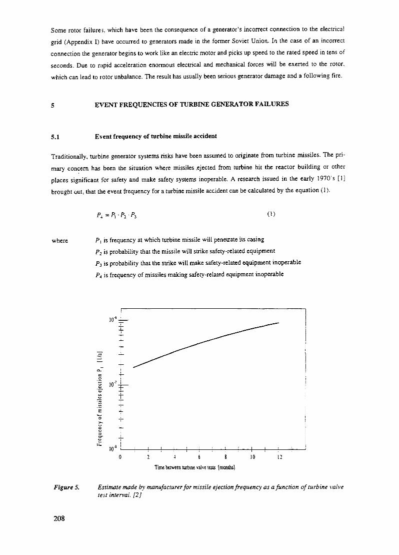
Some rotor failures, which have been the consequence of a generator's incorrect connection to the electrical
grid (Appendix I) have occurred to generators made in the former Soviet Union. In the case of an incorrect
connection the generator begins to work like an electric motor and picks up speed to the rated speed in tens of
seconds. Due to rapid acceleration enormous electrical and mechanical forces will be exerted to the rotor,
which can lead to rotor unbalance. The result has usually been serious generator damage and a following fire.
5 EVENT FREQUENCIES OF TURBINE GENERATOR FAILURES
5.1 Event frequency of turbine missile accident
Traditionally, turbine generator systems risks have been assumed to originate from turbine missiles. The pri-
mary concern has been the situation where missiles .ejected from turbine hit the reactor building or other
places significant for safety and make safety systems inoperable. A research issued in the early 1970's [1]
brought out, that the event frequency for a turbine missile accident can be calculated by the equation (1).
(1)
where P\ is frequency at which turbine missile will penetrate its casing
P2 is probability that the missile will strike safety-related equipment
P3 is probability that the strike will make safety-related equipment inoperable
PA is frequency of missiles making safety-related equipment inoperable
10*
10"'
12 4 6 8
Time between turbine valve tests [months]
10 12
Figure 5. Estimate made by manufacturer for missile ejection frequency as a function of turbine valvetest interval. [2]
208

As is recognised in reference [1], the frequency of missile ejection (P[) depends on the design of turbine rotor,
speed of rotation and thickness of turbine casing. Conservative estimate for P\ is 1CT* events per year. An
equally conservative estimate for P2 is 10'3. It is also conservative to estimate that a missile breaks its target.
If a turbine is oriented unfavourably towards safety-related systems, the frequency P2 may be 10"'. When
referred to the above estimates, the frequency for missiles making safety-related equipment inoperable (P4)
will be 10"7 per year for favourably oriented turbines and a maximum of 10'5 for unfavourably oriented tur-
bines.
The missile ejection frequency {Pi), based on operational experience, has a value as high as 1,25 • 10° per
year with a 90 percent confidence. The estimate has been gained by using operational data from Salem-2 and
other similar turbines manufactured by Westinghouse. Therefore the result is valid only for identical turbines.
According to [2] the ejection frequency P,, being between 10"9 - 10'\ depends not only on the turbine ">•
structure and speed of rotation, but also on operating practices, tests and inspections. How the missile pro-
duction is estimated to depend on the frequency of turbine valve tests at Salem NPP is brought out in figure 5.
The evaluation has been made before the accident at Salem-2 (see Appendix I).
In [3] the effect of turbine (low-pressure) casing inspection intervals on the missile ejection frequency Pi is
recognised. By increasing the inspection period from 4,5 to 9 years, P\ will quadruple. Inspections every 30
years increase the frequency of missile ejection over tenfold compared to a 4,5 years' checking interval.
Before the event the missile frequency of an individual plant or plant type can be estimated, the operational
history, monitoring, protection, tests and inspections of turbine generators must be studied in addition to tur-
bine generator plant features. Missile accidents or other rotational parts breaks have been rather unusual at
VVER-440 plants. Therefore the initial value for the missile ejection frequency Pi can be estimated to be 10
per year.
Hitting probability P2 at Loviisa-1 is examined in [4] and [5]. Studied targets located in turbine hall are
pumps and heat exchangers of the residual heat removal system and the conventional intermediate cooling
system's upper water tanks. Other targets, beside the turbine hall, are service water system's pumps and the
control room of the other unit, which are also in the range of the missile ejection angle. The order of magni-
tude of the probability is from 10^ to 10'3.
Referring to the information above, the frequency of the missile accident (P4) is low, a conservative assump
tion is 10'7 per year at Loviisa NPP.
At plants, where the turbines are situated unfavourably (like at an original WER-440 plant), turbine missik
risks are higher due to the fact that more safety related equipment are located along the trajectory of the mis
siles, thus the probability P2 is higher. Also, in the worst case scenario the heaviest missiles having an initia
velocity of several hundreds m/s may penetrate tens of centimeters of concrete constructions, thus possibh
striking also vital parts of the control building.
209

It is also important to notice the significance of operational procedures, tests, checks and monitoring. By
performing these functions in an appropriate manner the missile accident risk may be decreased by several
decades.
5.2 Turbine generator fires
5.2.1 Event frequency
Fire frequencies of turbine generator systems at American NPPs are calculated in [6]. Event frequencies are
based on 22017 years of operational experience from conventional power plants and on 577 years operational
experience from nuclear power plants. The results are shown in Table II. As the frequencies show, the fire
risk is higher for large turbine generators than for smaller ones. High NPP fire values are explained partly by
large NPP turbine generators.
Table 11.
period
1940-19491950-19591960-19691970-19791980-19831940-1983
Event frequency of turbine
60 - 2491,1 • 1 0 " 2
3,3 • 10"'1,9- 10"'3,4 • 10"'5,4 • 10"'
3,4 • 10"'
generator fires [fires/year].
conventional plants [MW]250-
-2,5-3 , 3 •
5 , 1 •
1,6-8,0-
499
10"2
10"'10"'10"2
10"'
5 0 0 ---
2,4 • 10"2
8,4 • 10"'
1,7- 10"2
12,7 • 10"'
[61
in all
1,1 • 10"2
3,6 • 10"'
2,5 • 10"'
4,3 • 10"3
9,7 10"'4,8 • 10"'
NPPs in all
--0
3.2- 10":
2,2- 10"2
2,6- 10":
The fire frequencies of various buildings at American NPPs have been presented in [7] from year 1994 (Table
III). Fire in the turbine hall seems to be the most common. The turbine building fire frequency is higher in
Table HI than in Table II. One reason is that the value in Table III includes also turbine building other fire
than turbine generator system fires.
Table III. Fire frequencies at American NPPs.
area fire frequencies [fires / year]turbine buildingauxiliary reactor buildingdiesel generator roomreactor buildingcontrol roomcable spreading roomservice water building
1,1 • 10'7,0 • 10"2
2,6 • 10"2
1,7- 10"2
7,2 • 10"'4,3 • 10"'2,0 • I0"3
According to insurance company statistics, the frequency of turbine generator system fires is 7,0 • 10° per
year. The frequency is calculated with data obtained by insurers (damages have exceeded the deductible). In
the case of economically serious fires (more than two million dollars reclamation) the frequency has a value
of 2,3 • 10"'per year.
210
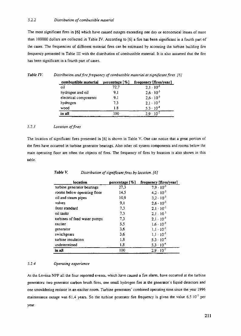
5.2.2 Distribution of combustible material
The most significant fires in [6] which have caused outages exceeding one day or economical losses of more
than 100000 dollars are collected in Table IV. According to [6] a fire has been significant in a fourth part of
the cases. The frequencies of different material fires can be estimated by accenting the turbine building fire
frequency presented in Table III with the distribution of combustible material. It is also assumed that the fire
has been significant in a fourth part of cases.
Table IV. Distribution and fire frequency of combustible material at significant fires. [6]
combustible material percentage [%] frequency [fires/year]oil 72,7 2,1 • 10"2
hydrogen and oil 9,1 2,6 • 103
electrical components 9,1 2,6 • 10'3
hydrogen 7,3 2,1 • 10"3
wood 1,8 5.3 • 10"1
in all 100 2,9 • 10 '
5.2.3 Location of fires
The location of significant fires presented in [6] is shown in Table V. One can notice that a great portion of
the fires have occurred in turbine generator bearings. Also other oil system components and rooms below the
main operating floor are often the objects of fires. The frequency of fires by location is also shown in this
table.
Table V. Distribution of significant fires by location. [6]
location percentage [%] frequency [fires/year]turbine generator bearingsrooms below operating flooroil and steam pipesvalvesfront standardoil tanksturbines of feed water pumpsexcitergeneratorswitchgearsturbine insulationundeterminedin all
27,314,510,99,17,37,37,35,53,63,61,81,8100
7,9 - 103
4,2 • 10"3
3,2 • 10°2,6 • 103
2,1 • 10°2,1 • 10"3
2,1 • 10'3
1,6- 10"3
1,1 • 10"3
1,1 • 1 0 - '5,3 • 10J
5,3 • 10"4
2,9 • 10"2
5.2.4 Operating experience
At the Loviisa NPP all the four reported events, which have caused a fire alarm, have occurred at the turbine
generators: two generator carbon brush fires, one small hydrogen fire at the generator's liquid detectors and
one smouldering resistor in an exciter room. Turbine generators' combined operating time since the year 1996
maintenance outage was 61,4 years. So the turbine generator fire frequency is given the value 6,5-10'l per
year.
211

In order to compare Loviisa's fire frequency to the value 1,1 • 10° taken from [7] we must assume, that the
value is the fire frequency of one reactor unit's turbine hall. In that case the corresponding value based on
operating experience from Loviisa will be 1,3 • 10"' fires per year. Then the frequencies are almost the same.
The first carbon brush fire in Loviisa can be considered significant in terms of [6] because the outage of this
turbine generator lasted over one month. So the allegation that a quarter of turbine generator fires is signifi-
cant seems to be in agreement with the Loviisa NPP operating experience.
The turbine generator systems of all Soviet-designed NPPs are essentially similar to each other. During their
operation history there have occurred at least three severe turbine hall fires (Armenia 1, 1982; Beloyarsk 2.
1978; Chernobyl 2, 1991) that required extraordinary and improvised recovery actions in order to prevent
core damage. Thus, according to normal PSA methodologies, the core damage frequency caused by severe
turbine hall fires in Soviet-designed NPPs could roughly be estimated to be of the order 3...5 • 10"3 per unit
year. However, design improvements and backfittings carried out at several plants as well as improved opera-
tion instructions can significantly reduce the risk figure.
6 SUMMARY
As the event frequencies presented earlier in this paper have proved, the most probable consequence of a
turbine generator failure is a fire. Because of large fire loads, mainly consisting of lubricating oil, the fire in a
turbine hall may grow very serious and may in the worst case make most of the systems situated in the turbine
hall inoperable. Other significant fire loads are the hydrogen used for the generator's cooling and the cables
and other electrical components, which are located everywhere in the turbine building. Due to high event
frequency and serious consequences it can be concluded that the risks of turbine generator failures are consid-
erable.
At a WER-440 nuclear power plant the risks induced by turbine generator systems are often more significant
than at Western NPPs, due to the location of some safety-related systems and the overall layout of the turbine
hall and the whole plant. The turbine hall is common for at least two units, and there are no walls or fire bar-
riers between the turbine generators and/or safety-related equipment. A turbine generator failure may thus
affect the operation of many systems, even the operation of the other unit. Also some other buildings, for
instance the control room building and the cooling water pumping plant, can be affected.
Large damages in a VVER-440 turbine hall may affect the primary circuit's residual heat removal from steam
generators. The most important safety-related systems located in the turbine hall are the main feed water sys-
tem, the emergency feed water system, the residual heat removal system and the steam lines from the steam
generators, including safety and isolation valves. Further details can be found in the paper "Safety improve-
ments at Loviisa NPP to reduce fire risks originating from turbine generators". As noted in that paper, an
independent back-up emergency feed water system and a fire barrier for protection of the control room
building and vital parts of the feed water and main steam lines are the most effective and also cost-beneficial
way to reduce the risks of turbine hall fires.
212
REFERENCES
1. Bush, S. H. Probability of Damage to Nuclear Components Due to Turbine Failure. Edited by J. R. Engel.
Nuclear Safety, 1973. Vol. 14, number 3. pp.187 - 201.
2. Ornstein, Harold L. Operating Experience Feedback Report - Turbine generator Overspeed Protection
Systems. Washington, USA: U.S. Nuclear Regulatory Commission, 1995. 50 pages. NUREG-1275, vol.
11.
3. Truong, V (Pacific Northwest Laboratory). Turbine missiles assessment. Nuclear technology, 1988. Vol.
82. pp. 21 - 35.
4. Loviisa 1-2, turpiinimissiilitarkastelu. Loviisa: Imatran Voima Oy, Loviisa NPP, 18.11.1977. 8 pages (in
Finnish). Internal report A-LO1-K350-499-010, not available.
5. Loviisa 1-2, turpiinimissiilit. Loviisa: Imatran Voima Oy, Loviisa NPP, 13.2.1979. 3 pages (in Finnish).
Internal report V-LO1-LO2-L350-499-013, not available.
6. Turbine Generator Fire Protection by Sprinkler System. Palo Alto, California: Electric Power Research
Institute (EPRI). 1985. EPRI NP-4144.
7. Ornstein, Harold L. Turbine Building Hazards. In: Fire & Safety '94. Barcelona, 5 - 7 December 1994.
Conference Papers. Sutton, UK: Nuclear Engineering International, 1994. pp. 77 - 82. ISBN 0617005583.
213
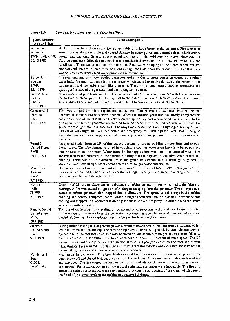
APPENDIX I: TURBINE GENERATOR ACCIDENTS
Table I.I: Seme turbine generator accidents in NPPs.
plant, country,type and date
event description
Armenia-1ArmeniaPWR, VVER-44015.10.1982
A short circuit took place in a 6 kV power cable of a large boron make-up pump. Fire started inseveral places along the cable and caused damage in many power and control cables, which causedseveral malfunctions. Generators connected spuriously to the grid causing several short circuits.Turbine generators failed due to electrical and mechanical overload. An oil leak set fire to TG2 andts oil tank. There was a total station black out. Feed water pumping to the steam generators was
stopped until the fire in the turbine hall was extinguished after two hours due to the fact that therewas only two emergency feed water pumps in the turbine hall.
Barseback-1 The retaining ring of a water-cooled generator broke up due to stress corrosion caused by a minorSweden water leak. The ring was blown into three pieces which caused extensive damage to the generator, theBWR lurbine unit and the turbine hall, like a missile. The short circuit ignited leaking lubricating oil.13.4.1979 causing a fire around the generator and destroying some cables.Beloyarsk-2RussiaLWGR31.12.1978
A lubricating oil pipe broke in TG2. The oil ignited when it came into contact with hot surfaces onihe turbine or steam pipes. The fire spread to the cable tunnels and electrical rooms. This causedseveral disturbances and failures and made it difficult to control the plant safety functions.
Chernobyl-2 TG4 was stopped for minor repairs and adjustment. The generator's excitation breaker and air-Ukraine operated disconnect breakers were opened. When the turbine generator had nearly completed itsLWGR coast down one of the disconnect breakers closed spuriously and reconnected the generator to the11.10.1991 grid again. The turbine generator accelerated to rated speed within 25 - 30 seconds. As a result, the j
generator rotor got into unbalance and its bearings were destroyed. Cooling hydrogen, sealing oil andlubricating oil caught fire. All feed water and emergency feed water pumps were lost. Lining analternative make-up water supply and reduction of primary circuit pressure prevented serious conse-quences.
Fermi-2 An ejected blades from an LP turbine caused damage to turbine building's water lines and to con-United States denser tubes. The tube damage resulted in circulating cooling water from Lake Erie being pumpedBWR into the reactor cooling system. Water from the fire suppression system and the damaged water lines25.12.1993 accumulated in the basement of the turbine building and the adjacent radioactive waste processing
building. There was also a hydrogen fire in the generator's exciter due to breakage of generatorsealings. Event caused significant damage to the turbine, generator and exciter.
MaanshanTaiwanPWR7.7.1985
Due to torsional vibrations of generator's rotor some LP turbine's blades broke. Rotor got into un-balance which caused break down of generator sealings. Hydrogen and an oil leak caught fire. Gen-erator and exciter were damaged badly.
Narora-1 Cracking of LP turbine blades caused unbalance to turbine generator rotor, which led to the failure ofIndia bearings. A fire was caused by ignition of hydrogen escaping form the generator. The oil pipes con-PHWR nected to turbine generator also snapped due to vibrations. Fire spread to cable trays in the turbine31.3.1993 building and control equipment room, which brought about total station blackout. Secondary side
cooling was stopped until operators started up the diesel-driven fire pumps in order to feed the steamvenerators with fire water.
Rancho Seco-1United StatesPWR19.3.1984
The loss of the hydrogen side sealing oil pump and other problems in the sealing oil system resultedin the escape of hydrogen from the generator. Hydrogen escaped for several minutes before it ex-ploded. Following a large explosion, the fire burned for five to eight minutes.
Salem-2 During turbine testing at 100 percent power a problem developed in the auto-stop trip system, whichUnited States ed to a turbine and reactor trip. The turbine stop valves closed as expected, but after closure they re-PWR opened due to the fact that some solenoid-operated valves of the turbine protection system failed to9.11.1991 open. Steam flow to the turbine led to an overspeed of about 160 percent of rated speed. The LP
turbine blades broke and penetrated the turbine shroud. A hydrogen explosion and fires and turbineubricating oil fires resulted. The damage in turbine generator systems was extensive, for instance the
turbine, the generator and the main condenser were damaged.Vandellos-1 Mechanical failure in the HP turbine blades caused high vibrations in lubricating oil pipes. SomeSpain sipes broke off and the oil leak caught fire from hot surfaces. Also generator's hydrogen leaked outGCGR and exploded. The fire caused the loss of control air and electrical power of several safety-related19.10.1989 components. For instance, two turboblowers and main heat exchanges were inoperable. The fire also
affected a main circulation water pipe expansion joint causing outpouring of sea water which caused:he flood of the lower levels of the turbine and reactor buildings.
214

APPENDIX II: TECHNICAL DATA OF TURBINE GENERATORS
This Appendix presents the most important technical parameters of the Loviisa NPP turbine generators. All
WER-440 plants have essentially similar turbine generators.
Table ILL Technical data of turbines at Loviisa NPP.
manufacturertypespeed of rotationshaft powerpower of HP turbinepower of LP turbinespressure of fresh steamtemperature of fresh steamflow of fresh steamsteam pressure after turbinesteam temperature after turbinesteam flow after turbineflow to tapping
Harkov turbine factoryK-220-44-23000 1/min235 MW105 MW130MW4,3 MPa252 °C350 kg/s2,5 kPa21 °C200 kg/s150 kg/s
Table //.//. Technical data of generators at Loviisa NPP.
manufacturertypespeed of rotationterminal pair numberfrequencyterminal voltageterminal currentapparent power (cos® = 0,9)active power (cos<p = 0.9)reactive power (cos<p = 0,9)
efficiency (coscp = 0,9)
Elektrosila, LeningradTW-220-2A3000 1/min150 Hz15,75 kV8960 A245 MVA220 MW108 MVAr98,7 %
215

PANEL 2
Panel 2
EXPERIENCE BASED DATA IN FIRE SAFETY ASSESSMENT
Chairperson: M. Rowekamp (Germany)
Members: F. Bonino (France)J. Martilla (Finland)N. Siu (USA)G. Wilks (USA)
The panel was opened by the statement of the chairperson that for deterministicas well as for probabilistic fire safety analyses more and more detailed, unbiased datahave to be made available to a broad community of fire safety experts including analysts.
The question arose what could be incentives also for nuclear industry to collectand make available further information and how to consider that some of this informationhas to handled carefully and confidentially. In this context, it was mentioned that thefuture stronger competition between European utilities could discourage nuclear industryin Europe to share information.
The willingness of the nuclear industry to participate in a broader collection offire related information and data was stated by one of the panel members as well as thewillingness of the participants to make an effort on preparing a common computerisedfire related database supported by modern communication systems like email. In thiscontext, there was a common understanding that the data have to be used appropriatelyavoiding any misuse of the information included and to protect the integrity and sourcesof data.
As the scientific secretary mentioned, the IAEA is not able to prepare andmaintain such a database. Furthermore, the participants expressed their doubts that theagency will only get information via the authorities/governmental institutions of themember states and therefore not always receive all the unfiltered/unbiased informationwhich the experts want to collect.
There was an agreement that knowledge on operating experience of nuclearpower plants (NPPs) world-wide is essential and that these data are needed to becollected. Volunteers are requested to build up and maintain such a database.
With respect to minor significant fire related events and precursor events forplant internal fires the panel members recognised difficulties in gaining the informationand consistency of this information. The scientific secretary asked the panel members andthe participants in the auditory how to get better information and consistency on firefrequencies and their uncertainties.
The analysts clearly expressed their needs for fire ignition models including alltypes of combustibles and potential ignition sources for characterising fire events.
There was a common understanding that there is still a deficiency with respect tothe knowledge on cable fires. Further activities including NPP specific tests and fireexperiments are needed.
Last not least, panel members as well as several experts from the auditory statedclearly that generic data, in particular those data related to fire protection features, haveto be handled carefully, considering differences in the manufacturing as well as ininspection and maintenance, quality control and assurance. With regard to the applicationof generic fire occurrence frequencies for probabilistic analyses, the available database,mainly from U. S. nuclear power plants, can only be used as a starting point for the plantspecific assessment.
:/i-^i. ii 219

FIRE SAFETY REGULATIONSAND LICENSING
(Session 5)
Chairperson
H.P. BERGGermany
IAEA-SM-345/43Key Issues Paper
FIRE SAFETY REGULATIONS AND LICENSING XA9847520
H.P. BERGBundesamt fur Strahlenschutz,Salzgitter, Germany
1. INTRODUCTION
Experience of the past two decades of nuclear power plant operation and resultsobtained from modern analytical techniques confirm that fires may be a real threat to nuclearsafety and should receive adequate attention from the design phase troughout the life of theplant. Fire events, in particular, influence significanty plant safety due to the fact that fireshave the potential to simultaneously damage components of redundant safety-relatedequipment. Hence, the importance of fire protection for the overall safety of a nuclear powerplant has to be reflected by the fire safety regulations and to be checked during the licensingprocess of a plant as well as during the continuous supervision of the operating plant.
However, in early designs of nuclear power plants fire events were not identifiedaccording to its actual risk for nuclear safety. Regular industrial standards for fire protectioninstallations were adopted and only somewhat altered to ensure that radiological release waskept within the plant.
The fire at the Browns-Ferry nuclear power plant in 1975 and the development of thegeneral defence-in-depth concept for nuclear power plants have resulted in an improved fireprotection strategy which can be achieved by a combination of:
• an adequate design,• a safety culture, which promotes a proper attitude and ensures continued personnel
awareness of potential hazards from fire,• effective fire prevention and fire protection measures,• an appropriate level of quality assurance, and• emergency plans and procedures.
To ensure an adequate fire safety level for all operating plants, the defence-in-depthconcept covers the following principal objectives:
• preventing fires from starting,• detecting fires anywhere in the plant promptly and extinguishing quickly those fires
which do start, thus limiting the damage,• preventing the spread of those fires which have not been extinguished, thus avoiding
any common cause failure mode and minimizing their effect on plant safety systems,and
• designing safety systems in such a way that even if a fire spreads within a plant area,the fire will not interfer with the performance of essential plant functions.
223
In order to protect the health and safety of the public from the potential consequenceswhich a fire may have on reactor safety, each of these principles should meet certainminimum requirements prescribed in regulations or in the license. Strengthening one of theseareas may compensate in some measure for weaknesses, known and unknown, in the otherareas.
Hence, this new approach is also reflected in more current regulations and in licenses ofnuclear power plants of the last generation; however, there was also a need for methods todetermine the adequacy of the fire protection programme in plants built to earlier standardsand to regulate backfitting measures to enhance the fire safety protection.
Moreover, the knowledge in fire science has increased considerably over the last twodecades. Better methods for measuring and analysis have made it possible to look into thebasic physics and chemistry of combustion. Modelling of fires has been improved by fluiddynamic science, especially turbulence modelling, and by computer development. This is alsoa reason of today's trend in some countries to introduce performance-based regulations toreplace prescriptive ones.
2. FIRE SAFETY REGULATIONS AND LICENSING
Even in the early years of the design and operation of nuclear power plants, design andregulations have always considered fire safety to some extent. However, nuclear specificrequirements and standards related to fire protection were not fully developed.
Nuclear power plants had to meet applicable building codes and standards - the samewhich were used for other types of industrial facilities and even for office complexes. Thesenon-nuclear regulations contain national and international industrial standards, laws andordinances for building constructions as well as for fire brigade management and equipment,and ordinances regarding the work place safety. In addition, usually general design criteriaand/or safety criteria had described general requirements for fire prevention, detection andresponse. International guidance is, e. g., provided in [1].
For example in Germany, fire safety is addressed in the safety criterion 2.7 ,,Fire andExplosion Protection", of the Safety Criteria for Nuclear Power Plants (1977) and the IncidentGuidelines of 1982 requiring that protective measures against fires shall be taken by means ofplant engineering. The specifications of these precautions were intended to be outlined in fournuclear safety standards describing and prescribing the basic principles, fire safety measuresfor structural components, fire safety measures for mechanical and electrical components andrescue routes in nuclear power plants. However, only the standard on basic principles has beenpublished. The status of these standards, the benefits and problems with very detailedstandards are explained in [2].
Experience shows that very detailed regulations, focused on a specific plant type, areonly reasonable if a series of the same plant type is constructed. Otherwise, there appearsalways the problem how to apply these standards to nuclear power plants built to earlierstandards.
224

These insights advocate that countries establishing or reorganising fire protectionregulations should share the experience gained by other regulators.
In [3], general fire protection guidelines for Egyptian nuclear installations are described.Again, the requirements given shall only be applied to new nuclear facilities whereas fireprotection modifications of operating plants are considered case by case. This ensures anadequate planning of fire protection measures as an integral part of the design phase andthroughout the life of the plant.
Also in the Russian Federation, a revision of the regulatory nuclear frameworkincluding fire protection for nuclear power plants has been performed recently and is furtherdeveloped in 1998 to require a fire safety analysis as part of the operational licensingdocuments. The fire safety aspects are supervised by the surveillance anthority in closecooperation with a central national fire protection institute which is in the portfolio of theMinistry of the Interior [4].
An important discussion on a fundamental change in fire protection regulations to datehas started in the US by proposing a performance-based approach to fire safety and thusmaking decisions on the basis of fire risk assessments. The regulator's position and the pointof view of the utilities are presented in [5] and [6] showing the benefits and problemsconnected with this new approach. Due to the intended increasing flexibility for the utilitiesthe industry position to maintain the existing regulations and to believe that new rulemakingis not required is an unexpected perspective which is outlined in more detail in [6].
3. KEY ISSUES
Based on past experience, the following key issues for fire protection regulations can beidentified:
• laws and ordinances have to define safety goals, general requirements and ways toprove that these goals and requirements are fulfilled,
• standards have to provide the technical basis to achieve an adequate fire safety level,and these standards change with time due to an increase of scientific knowledge andoperational experience,
• very detailed and prescriptive standards are helpful in the licensing process becausetheir application simplifies the discussion with the authorities and expert groups andsupports possible court decisions regarding the necessary fire safety level of a plant,
• all regulations and standards have their limits; when using them, understanding oftheir background and context is sometimes of great importance and not asophisticated interpretation and fulfillment word by word,
• if very detailed fire protection requirements, e. g., on the equipment are prescribed,also the necessary procedures to check the fulfillment should be determined, i. e.
225

which fire qualification tests are necessary and in which cases qualification bycomputer codes are sufficient; this is important to make sure that the testingprocedure is representative for the application where the system is to be used and thatonly verified computer codes are applied,
• regulations should not only cover design and construction aspects important in thelicensing process but also provide a reasonable procedure for continuous supervisionand regular review of the fire safety level of nuclear power plants built to earlierstandards on the basis of current standards because a direct application of currentstandards to older plants is not always suitable,
• modern regulation should take into account the use of probabilistic methods as asupplementary tool to deterministic methods, in particular for evaluating the firesafety level of plants in operation.
4. CONCLUDING REMARKS
Due to the fact that fires are complex phenomena resulting not only from ignition andcombustion processes, but also from its impact on safety - related equipment und from thenecessary appropriate response of the operators, fires have still to be considered also inmodern plants; however, main emphasis remains on nuclear power plants built to earlierstandards, in order to ensure the adequate level of fire safety.
In consequence, regulatory anthorities have developed requirements to establish levelsof fire safety which must be provided in nuclear power plants. Some of these guidancedocuments are broad, more performance-based regulations while others are more prescriptiveand offer only few choices for the designer, the operators and also the authorities and theirexperts.
The trend of the US Nuclear Regulatory Commission to change from prescriptiveegulations to a risk-informed, performance-based regulation not only in the field of fireprotection will be carefully observed and analysed by the European regulators but notfollowed in the near future. Practical experience will show if this new approach will fulfill theexpectations to further improve the fire safety level in a most efficient and cost-effectivemanner, both for the regulators and the utilities.
REFERENCES
[1] International Atomic Energy Agency, Fire Protection in Nuclear Power Plants: A SafetyGuide, IAEA Safety Series Nr. 50-sg-D2 (Rev.l), IAEA, Vienna (1992).
[2] Wittmann, R., Fire Safety Regulations for Nuclear Power Plants in Germany, IAEA-SM-345/11, these Proceedings.
[3] Rashad, S. M, Hussein, A. Z., Hammad, F. H., General Fire Protection Guidelines forEgyptian Nuclear Installations, IAEA-SM-345/12, these Proceedings.
226

[4] Pogorelov, V. I., Fire Safety Regulations for NPPs in Russian Federation Legal Basisand Licensing Experience, IAEA-SM-345/13, these Proceedings.
[5] Dey, M, Development of a Risk-Informed, Performance-Based Regulation for FireProtection at Nuclear Power Plants, IAEA-SM-345/41 I,
[6] Emerson, F. A., Industry Participation in the Development of a Risk-Informed,Performance-Based Regulation for Fire Protection at US Nuclear Power Plants, IAEA-SM-345/42 I, these Proceedings.
227

IAEA-SM-345/11
FIRE SAFETY REGULATIONS FOR NUCLEAR POWER PLANTSIN GERMANY AND THE VARIOUS DIMENSIONSOF GERMAN KTA STANDARDIZATION ACTIVITIES.IS THERE A BENEFIT TODAY?
XA9847521R. WITTMANNSiemens AG Power Generation,Erlangen, Germany
Abstract
In Germany the mandate for preparing nuclear safety standards is given to the KTA (NuclearSafety Standards Commission) which has restrictive procedures to definitely ensure consensusprinciple. The KTA was up to now not in a position to approve comprehensive fire safety relevantstandards, although its corresponding program is now 22 years old. KTA 2101.1 "Basic Principles ofFire Protection in NPPs" (12/85) is the only one published as valid safety standard. Drafts for 3additional standards referring fire protection of structural elements, electrical and mechanicalcomponents as well as for rescue routes have been agreed upon in working groups, supervised andaccepted by the responsible KTA subcommittee, but have not been approved by the full committee ofthe KTA up to now. Some of these drafts are already more than 5 years old. From the toady's point ofview the earliest possibility to have a comprehensive and actual set of fire relevant KTA standardswill be in the second half of the year 1999. This would then be 24 years after the first KTA decisionto start such a program.
1. German Nuclear Safety Standards Commission (KTA)Legal Background, Organization and Procedures
In Germany the legal basis for the licensing of nuclear power plants and other nuclearinstallations is the Atomic Energy Act. Amongst others it defines that license can only beobtained ,,if every precaution which is necessary in the light of existing scientific andtechnological knowledge is taken in order to prevent damage caused by the construction andthe operation of the plant". So in each individual case the nuclear licensing authorities have todecide whether these requirements have been met by the technical equipment or theorganizational procedures the applicant intends to install in a nuclear facility. In the earlystage of nuclear power technology in Germany licenses were primarily based exclusively onindividual evaluation and review, existing technical standards were more or less only valid forconventional that means non-nuclear buildings and did therefore not reflect specific nuclearaspects.
Thus, at the end of the decade of 1960 the need for nuclear safety standards and an elaboratingresponsible institution was obvious. It is facet of German technical legislation and has longlasting tradition that technical safety standards are developed by commissions which areappointed by Ministers of the Federal Government rather than by governmental agencies or byprivate institutions. Such commissions were the model for the formation of the GermanNuclear Safety Standards Commission, the KTA, which finally was founded in the year 1972and was at that time given into the responsibility of the German Federal Minister of theInterior. It belongs to the realm of the public law and is indeed neither a governmental agencynor a private organization, like the German Standards Institute (the DIN) or the AmericanSociety of Mechanical Engineers (the ASME) or the American Nuclear Society (the ANS).
229
The commission of the KTA consist of 50 members. Representatives of 5 groups with 10persons each, who met in former times three time a year, nowadays only once a year. Thegroups are (1) the manufacturers and vendors of nuclear facilities, (2) the operators/utilities ofnuclear facilities, (3) the state licensing authorities and the federal authorities that supervisethem, (4) the safety reviewing and advisory organizations and last but not least (5) the otherauthorities, organizations and institutions dealing with or involved in nuclear technology. The50 members are nominated for a period of 4 years, the board consists of 5 persons, one of eachgroup. The principle is that the partners cooperate as equal partners and make their decisionby consensus. All decisions which are directly related to the establishing of standards must beagreed to by five-sixths of the members who participate in the individual full session of theKTA. This procedure shall ensure that no one of the five groups can be outvoted when adecision has to be taken. Each standard is first published as a draft standard and the public isinvited to comment on it within a period of 3 months. Comments received are discussed andtaken into account, as appropriate, before then the final version is established and publishedby the German Federal Minister of the Interior in Federal Gazette.
The preparation of the safety standards is not done by the 50 members of the KTA, but byworking groups and supervising subcommittees. They are supported by a scientific technicalsecretariat. The working group members are experts in the fields of interest and are nominatedby the different institutions and companies belonging to the 5 groups of the KTA. Themembers of the subcommittees are nominated by their institutions , but in addition officiallyappointed by the KTA. Subcommittees have to supervise and coordinate the activities of theworking groups which report to them. The draft standards prepared by the working groups arereviewed by the subcommittees before submission to the KTA. If necessary, the drafts arereferred back to the working group and further discussion is initiated. Subcommitteesgenerally have also to review comments received from the public after the publication of thedraft standard £jid generally have to prepare the final version of the standard. So man canimagine that developing a KTA safety standard is rather complicated and slow.
Provisions are also made for to keep published KTA safety standards actual. Thesubcommittees are responsible for regularly checking the validity of the standards and, ifnecessary, making recommendations to the commission of the KTA as to alternations deemednecessary to bring a standard up to date.
2. KTA Program and Progress of its Fire Safety Relevant StandardsKTA 2101 Part 1 to 3 and KTA 2102
2.1 Initial Program for Fire Protection and Related Activities
To establish uniform fire protection requirements for nuclear power plants and to harmonizethe different licensing activities in the various fields and responsibilities involved, thecommission of the KTA decided to establish the safety standard set KTA 2101 ,,FireProtection in Nuclear Power Plants" in November 1975. This set was defined to have thefollowing three parts:
Part 1: Basic Principles
Part 2: Structural ElementsPart 3: Mechanical and Electrical Components.
230

In November 1976 there was an additional KTA-decision to complement the safety standardset KTA 2101 ,,Fire Protection of Nuclear Power Plants" by the standard KTA 2102, whichshould deal with ,,Rescue Routes in Nuclear Power Plants" which is a very important fireprotection issue to ensure primarily personnel safety. Four different working groups had beenestablished in a relatively short time after, with experts of all the relevant different groups ofthe KTA. Thus it was ensured that all the different and relevant aspects and implications willbe acknowledged early and taken into consideration while drafting the standard. For all these4 issues so-called preliminary reports with literature studies, collection of licensing experienceand first proposals for scope and content have been derived by the working groups andsupervised by the responsible subcommittee. These preliminary reports were accepted by thecommission of the KTA at its full sessions between February 1978 and October 1979. Thus,at that time it became obvious that there was a common understanding between authorities,utilities, manufacturers and safety reviewing organizations for a realistic possibility for a lateracceptance of the different safety standards for fire protection. At that time, at the end of theseventies, the average time period between the first working group meeting and the closingofficial decision of the KTA for the acceptance of a standard was about 5 years. So the KTAfire protection standard set was ought to be finished by the years 1982/83.
This was not possible due to many reasons. Some are the following ones:
The issue of fire protection is in addition to its nuclear implication an important part ofdifferent conventional building laws, which in Germany are per definition independentstate laws and are therefor not governed by federal laws, like the Atomic Energy Act. Thus,time consuming discussions have been necessary to harmonize the different strategiesbetween different authorities to reach the goals.The theoretical concept for the combination of plant-internal respectively -external eventswith consequential and related fires, which was drafted in KTA 2101.1, was absolutelynew and had to be detailed and explained during many discussions. For a fire protectionengineer it was at that time very strange to think about design principles for fires incombination with other extremely seldom events.The new strategy to define necessary fire resistance ratings of structural elements by ananalytical method and no more by prescriptive values, coming from conventional buildinglaws and codes, was a little bit like a revolution in German fire design practice.Revolutions normally take time, also in fire protection standardization where in the pastmost requirements have been based on empirical data.The scope and content which was originally planned by the working group for ,,electricaland mechanical components" was very detailed and therefor opposed those experts whowanted to keep the KTA safety standard more flexible in general than more precise indetail.
But despite all these problems all working groups in charge finally had been able to findcommon understanding for the requirements on fire protection basic principles (KTA 2101.1),on fire protection of structural elements (KTA 2101.2), of electrical and mechanicalcomponents (KTA 2101.3) and on measures to ensure rescue and escape of personnel duringfires (KTA 2102). In the course of further discussion the responsible KTA subcommittee alsoaccepted the drafted papers and decided to convey them to the KTA to get the approve as draftstandards respectively as standards.
231
KTA 2101.1 was published as safety standard in 12/85.KTA 2101.2 was ought to bee published as draft safety standard in 1993, but was notaccepted by the commission of the KTA. It has therefore still the status of a draft safetystandard in preparation (issue 06/93).KTA 2101.3 was published as draft safety standard in 06/94. After having discussedcomments and proposals from the public it was revised by the working group and acceptedby the supervising subcommittee 2 years later in 04/96. This status still exists up to now.KTA 2102 was published as draft safety standard in 06/90. Comments especially fromrepresentatives of the German official body, responsible for life and health of workingpeople in general, have led to a revision of the paper, for which the commission of theKTA was asked for official approve as safety standard in 1992. Up to now no 5/6consensus was possible within the commission of the KTA in order to publish it as a validsafety standard. Especially since 1992 the operators of the German nuclear power plantsargue about the question whether it makes sense to integrate issues of the conventionalbuilding code in nuclear safety standards. In this context it is worthwhile to know that inGermany in the sphere of influence of conventional building laws there is an inventoryprotection for the owners of a building, which does not exist in nuclear affairs wherenormally he actual state of science and technology form the basis for licensing procedures.This is also the reason why KTA 2101.2 was not published as official safety standard up tonow.
Within the year 1996 - 21 years after the original first decision of the KTA - a group ofunshakable optimists (members, especially chairpersons of all the different working groups ofKTA 2101) came together to harmonize the different papers, mentioned above. There was anofficial resolution of the commission of the KTA to do this, in order to get a set ofcomprehensive requirements at nearly the same level of science and technology, and to comeover with the problem of all these different dates of issue. Additionally a small working groupof experts who have bee involved in the first preparation of the sole approved KTA 2101.1,,Basic Principles of Fire Protection in NPPs" (issued 12/85) have met several times in 1996and 1997 to prepare a revision of the more than 10 years old safety standard which shouldespecially take into consideration the advanced KTA-concept for earthquake design of nuclearpower plants and the proposals for the other parts of KTA 2101. Due to general strategies ofthe KTA for keeping the existing safety standards up to date, the feedback from experiencewith the existing safety standard is regarded as most valuable and should therefor also beconsidered during revising an existing standard.
These activities have been completed in 03/97. The result was accepted by the supervisingsubcommittee in 04/97. Consequently new drafts of harmonized and updated safety standardsKTA 2101 parl 1 and 2 were again conveyed to the KTA to get the approval as drafts at itssession in 06/97. The new draft of KTA 2101.3 was not given to the KTA for the content wasalready accepted by the KTA recently and was only editorially modified. The subcommitteeasked the KTA to approve part 1 and 2, both as draft safety standard, in order to give them tothe public and to receive comments from the public.
Both papers had been put on the agenda of the full session in 06/97, but in the very lastmoment the commission of the KTA decided to delete the topic for KTA 2101.2 ,,FireProtection of Structural Elements in NPPs", for some members of the KTA had not foundenough time to be prepared for being able to vote about its publication as draft standard.
232

KTA 2101.1 has been in fact discussed by the KTA members, but has not got the necessary5/6 consensus to be accepted as draft version. It was obvious that the representatives of statelicensing authorities refused. Representatives of federal authorities and of the safety reviewingand advisory organizations voted as positive as manufacturers and most of the utilities. Butdue to the necessary 5/6 consensus they did not succeed. The day after that KTA full sessionin 06/97 there was an extensive article in a German newspaper entitled ,,Play with fire at thenuclear power plant fire protection". In the article it was pronounced that ,,it was indeed alast-minute action of the representative of the state licensing authority of Hessen, where theBiblis npp is located, to avoid that the German utilities and the federal minister responsiblefor licensing ofnpps could reduce the fire protection requirements to an unacceptable level".For the author and other people it became obvious that discussions about the content ofupdated fire safety relevant KTA standards seem to be influenced by the different opinionsabout the role and future of nuclear power in general. Seeing that background it can be arguedwhether there will be a realistic chance to find a common , that means 5/6 understandingabout revised requirements for this issue in the future.
In order to get technically qualified arguments for clarifying the rejection of the abovementioned parties the secretariat of the KTA had now sent all the actual drafts of the 3 parts ofKTA 2101 (again) to the different fractions of the KTA shortly after its full session in 06/97.Till the end of October this year (deadline for submission) some comments have been sent tothe KTA secretariat, the most extensive one was sent by the German state licensing authorityof the state of Hessen, where the 2 elder nuclear power plants at the site of Biblis are located.This comment consists of more than 40 pages.
As man can see, a former huge program for the development of German nuclear safetystandards in the fields of fire protection got stuck in the quicksand of higher politicaldecisions. All relevant technical aspects have been agreed upon within the responsibleworking groups and subcommittees. For the elaborating of the 3 parts of KTA 2101 and KTA2102- neglecting the preceding time period for the so-called preliminary reports - 164 officialworking group meeting have taken place, most of them lasted 2 days. At each individualmeeting about 15 high qualified experts took part. Due to experience, the preparing time ofeach participant can be estimated at least three times the course of the working groupmeetings themselves. So up to now, far more than 10.000 man-hours have been spent byrepresentatives of all the different KTA-groups. Referring that background it is indeed a pitythat only one (1!) part of KTA 2101 - the part dealing with basic principles - was agreed uponas valid safety standard. During the eighties the velocity for progress was influenced by theconflicts between existing atomic and conventional requirements, during the nineties it wasthe conflict between acceptance or rejection of nuclear power in general, also within thedifferent groups of authorities with nuclear responsibilities.
2.2 Some Published or at least Proposed Requirements2.2.1 KTA 2101.1 ,,Fire protection in Nuclear Power Plants; Part 1: Basic Principles"
(issued 12/85)
All relevant issues are treated with, like e.g.
basic design-philosophy including the special protection of safety relevant features, theoverall-postulate of fires in case of the existence of burning material and the considerationof consequential and unrelated fires with plant-internal and -external events as well as
233
basic design requirements for structural and equipment related fire protection measures andoperational fire protection measures andtests and inspections.
Referring structural measures it is e.g. stated that basically incombustible constructionmaterial shall be used, that fire zones shall be created inside the structures and that the fireresistance rating of walls and ceilings of fire zones shall be at least 90 minutes. Specialconsiderations are included for closures of openings in fire qualified walls and ceilings.
Requirements for equipment related fire protection measures refer e.g. to the special situationinside containment, the design principles for fire alarm and fire suppression systems, forsmoke and heat removal as well as for fire protection measures for ventilation systems andoff-gas systems.
Referring the issue of tests and inspections for example details for tests prior to the granting ofa construction or assembly license are to be seen as well as for the supervision of theconstruction and for tests prior to the commissioning of the npp and after major repairs andmodifications.
2.2.2 KTA 2101.1 ,,Fire protection in Nuclear Power Plants; Part 1: Basic Principles"(draft version 04/97)
As mentioned in section 2.1 a working group had drafted an updated version of KTA 2101.1with the aim of primarily harmonizing with the complementary part 2 and 3 but also with theaim to clarify the wording, where in the past misinterpretation and misunderstanding becameobvious. That was one of the reasons why the members of that new working group in 1996/97had been derived out of that former working group which was originally responsible for KTA2101.1 from the very first beginning. So it was ensured that the original intention was knownin the working group.
From the point of view of the working group members (representatives of authorities, safetyreviewing companies, utilities and manufacturers) most of the alterations are editorial, but asmentioned in section 2.1, especially one state authority feels that the alterations can lead to anoverall degradation of fire safety in German npps in the future. From that the conclusion couldbe drawn that the clarifications made by the working group and accepted by the responsiblesupervising subcommittee have met those fields of interpretation-possibilities which are ofsignificance for groups which want to reject nuclear power in Germany.
For further information on the content of the new drafted standards the official secretariat ofthe KTA, which is part of the ,,Bundesamt fur Strahlenschutz" in D-38201 Salzgitter shouldbe contacted.
2.2.3 KTA 2101.2 ,,Fire protection in Nuclear Power Plants;Part 2: Structural Elements" (draft version 04/97)
This draft version was agreed upon within the responsible working groups and sub-committee. The most important difference between that draft version (06/93) mentioned insection 2.1 is a totally new analytical concept for the definition of necessary fire ratings of
234

walls and ceilings of fire zones and the closures of openings in these structures. This method,which is based on the actual state of the art in this field of interest in Germany was primarilydeveloped by Prof. Hosser from the University of Braunschweig, Germany and funded by theGerman federal government. The project management for this development was made by theGesellschaft fur Reaktor- und Anlagensicherheit (GRS) in Cologne which is a nuclear safetyreviewing organization.
In this new draft it is required that in cases with a lack of experience the fire proof design ofstructural elements has to based on either experimental, analytical, plausibility or analogyconsiderations. When analytical proof is necessary, simplified methods will be allowed. Sucha method is part of the draft standard. Necessary fire ratings could now be derived by takinginto account real existing fire load, room geometry, ventilation properties, heat sinks, kind offire extinguishing concept/system and last but not least the safety relevance of the structuralelement to be designed.
2.2.4. KTA 2101.2 ,,Fire Protection in Nuclear Power Plants;Part 3: Electrical and Mechanical Elements" (draft version 04/97)
This draft version agreed upon within the responsible working groups and sub-committeeDetailed requirements referring fire detection and fire suppression systems are included aswell as specific measures for mechanical components, for electrical equipment and forventilation systems.
For further information on the content of the actual draft version of this standard the officialsecretariat of the KTA, which is part of the ,,Bundesamt fur Strahlenschutz" in D-38201Salzgitter should be contacted.
2.3 Changing Attitudes in Nuclear Issues and their Influence on Completing theKTA Program
The KTA nuclear safety standards have merely been developed for the design, supervisionand license of new nuclear plants. Their application on supervision and control of existingnuclear power plants have not at all been in the center of interest during the first 25 years ofKTA working period, beginning in 1972. Within the last 5-10 years the conviction wasincreasing in Germany that in the nearer future no new nuclear power plants will be necessaryin Germany to guarantee the supply of electricity. Since that time and also in the futureactivities for design, supervision and license of nuclear facilities will primarily concentrate onthe safety assessment of existing elder plants, also in respect to fires. In this context KTAstandards can be worthwhile for court proceedings as e.g. anticipated technical opinion of thesafety reviewing organizations. For existing elder npp, it is very essential that KTA standardsare applied appropriate for they have not been developed for the purpose of reviewing,supervising existing elder plants. That means they have to be applied safety goal orientated,not word by word, without degrading safety level.
This strategy is valid for all safety aspects and especially also for fire safety, for it is fact thatthe issue of fire safety has not been in the center of interest in the beginning of nuclear powerplant design and license about 25 years ago. Within the last 10 years a lot of fire safetyreviews and corresponding upgrading activities for elder plants have taken place in Germany.Most of them lasted several years, swallowed a lot of money and were based on the abovementioned safety goal orientated strategy. Only in some cases the applicant for upgrading
235

measures and in some cases also the responsible safety reviewing organization have gottroubles with some state licensing authorities, the representatives of which stuck too much onthe detailed wording of existing KTA standards.
Those German nuclear power plants which have not been involved in larger fire safetyreviewing and upgrading programs within the last 10 years have been designed and licensedduring that period where the KTA 2101 safety standard program was developed. Thereforethese plants are already designed in compliance with the relevant requirements of KTA 2101.
Within the last decades the KTA standardization activities have mostly been regarded ascontribution to ensure a specific safety level within national German boundaries. The lastdecade dominantly demonstrated that nuclear power will not have an independent nationalfuture and that international cooperation will move dominantly forward. Safety standards arean integrated part of this movement. It would be a bad result if the KTA and its members builta blockade on this way.
Beside the national safety relevant standardization activities, new chances for an internationalfuture in this field do exist and should be used. One chance will be the program of the IAEA,another chance for the future of standardizing lies e.g. in the bilateral efforts of German andFrench government to define common safety requirements for future nuclear power plants.Focusing on fire safety a so-called European Technical Code Fire (ETC-F) was prepared byEdF, Framatome, German utilities and Siemens (KWU) within the last 2 years and conveyedto French/German nuclear safety reviewing and advisory organizations in October 1997.
3. European Requirements for a new Type of Pressurized Water Reactor (EPR);Alternative or Amendment to KTA Standards?
As mentioned in section 2.3, within the last 2 years a so-called European Technical Code Fire(ETC-F) was drafted by French and German experts and was handed over for comments andapprove to officially nominated safety reviewing organizations in both countries. The draftedETC-F is based on existing national fire safety regulations or at least drafts of them, like theFrench RCC-I and the German KTA 2101.1 - 3 and KTA 2102 and is intended to describethat necessary fire safety level which has to be ensured during design of new type ofpressurized water reactor, the so-called EPR, which will be built in the future as a cooperationbetween both countries and will be launched to the international market by about the end ofthe century.
Contrary to German KTA procedure, but in harmony with the French practice, the ETC-F wasexclusively drafted by the industry and then given to nuclear authorities and their consultant.Governments of both countries did accept this strategy. It is too early to conclude that thedrafted content will be accepted without any alterations but first discussions show that thebasic design relevant fire safety design principles could be agreed upon.
Looking in the future there could be the following understanding:
The requirements of KTA standards describe the necessary safety level of existing Germannuclear power plants, designed and licensed exactly at or after the time when the standardshave been approved and form therefore the basis for additional reviews and upgradingactivities of these plants.
236
For future new nuclear power plants in Germany the basic design principles are described inthe ETC-F. Specific additional national requirements for detail design could be stipulated inthe different parts of KTA 2101 and in KTA 2102. So the KTA standards would beamendments and not alternatives to the growing European Technical Code Fire (ETC-F).
4. Conclusion
The German safety standard commission KTA was up to now not in a position to approvecomprehensive fire safety relevant standards, although its corresponding program is now 22years old. KTA 2101.1"Basic Principles of Fire Protection inNPPs" (12/85) is the only one asvalid safety standard. Drafts for standards referring fire protection of structural, electrical andmechanical elements as well as for rescue routes have been agreed upon in working groups,supervised by the responsible KTA subcommittee, but not approved by the full committee ofthe KTA. Some of them are already more than 5 years old.
There seem to be no more interest to realize KTA 2102 as valid standard. As the fullcommittee of the KTA meets only once a year, approved standards for KTA 2101.1 ,,BasicRequirements" (first revision), KTA 2101.2 Structural Elements" and KTA 2101.3,,Electrical and Mechanical Components" will not be available until the second half of theyear 1999, that means 24 years after the decision of the full session of the KTA to start thisprogram.
The next few months, where again working groups are asked to discuss comments from thedifferent fractions of the KTA, will show whether the members of these groups arefurthermore willing to spend their time and money of the companies/organizations they arecoming from. Perhaps the activities will be put to an end without having an approved set offire related KTA safety standards. The existing papers could then at least be regarded as thatstate of science and technology the responsible working groups have agreed upon. This wouldat least be worthwhile for education of young engineers and for information of interestedcompanies/organizations from foreign countries.
Countries and governments which in this very moment reflect on establishing an own nuclearsafety standardization program should learn about that what is described in this paper. Findinga consensus on technical aspects on behalf of elaborating safety standards is very sensible,especially when commercial markets are no more closed and open for everybody, but it isnecessary that the time to find consensus is not too long. To be able to realize this it isnecessary generally to restrict on basic principles and not concentrate on detailedrequirements. Such requirements should be left into the responsibility of specific licensingand supervising process.
BIBLIOGRAPHY
(1) KTA 2101.1 "Brandschutz in Kemkraftwerken;Teil 1: Grundsatze des Brandschutzes" (Regel 12/85)
(2) KTA 2101.1 "Brandschutz in Kemkraftwerken;Teil 1: Grundsatze des Brandschutzes" (Regelanderungsentwurfsvorlage 04/97)
(3) KTA 2101.2 "Brandschutz in Kemkraftwerken;Teil 2: Brandschutz an baulichen Anlagen" (Regelentwurfsvortage 04/97)
237

(4) KTA 2101.3 "Brandschutz in Kemkraftwerken;Teil 3: Brandschutz an maschinen- und elektrotechnischen Anlagen"(Regetvorlage 04/97)
(5) KTA 2102 "Rettungswege in Kernkraftwerken"(Regetvorlage 03/92)
(6) J.Freund, G.Philip, W.Schwarzer The Nuclear Safety Standards Commission of theFederal Republic of Germany"(Nuclear Safety, Vol. 25, No. 5, September-October 1984)
(7) MinDirig H.Steinkemper, BMU "GruBworte zur 50. Sitzung des KTA am 11.06.1996"
238
IAEA-SM-345/41Invited Paper
TECHNICAL METHODS FOR A RISK-INFORMED,PERFORMANCE-BASED FIRE PROTECTION PROGRAM ATNUCLEAR POWER PLANTS*
•* <f -~r T^T^ ^ T ' Hill I l l l l l l I I I ! IIIBI Illll • • • • • I»BI •Mil II
United States Nuclear Regulatory Commission,Washington, D.C.,United States of America
Abstract
This paper presents a technical review and examination of technical methods that are availablefor developing a risk-informed, performance-based fire protection program at a nuclear plant. Thetechnical methods include "engineering tools" for examining the fire dynamics of fire protectionproblems, reliability techniques for establishing an optimal fire protection surveillance program, firecomputer codes for analyzing important fire protection safety parameters, and risk-informed approachesthat can range from drawing qualitative insights from risk information to quantifying the risk impact ofalternative fire protection approaches. Based on this technical review and examination, it is concludedthat methods for modeling fires, and reliability and fire PRA analyses are currently available to supportthe initial implementation of simple risk-informed, performance-based approaches in fire protectionprograms.
1. INTRODUCTION
Historically, requirements for fire protection programs in the general building industry andnuclear power plants have been formulated based on deterministic criteria and prescriptive innature [1]. In many cases engineering judgment of experts was used in determining fireprotection features such as the allowable minimum width of hallways and number of firedetectors and sprinklers for buildings, and the allowable minimum safe separation distance andfire barrier ratings for nuclear power plant safe-shutdown trains. Given the advances inprobabilistic risk assessments (PRAs) and fire sciences, fire protection programs can now berevised from being deterministic and prescriptive to more risk-informed and performance-based[1.2].
In a broad sense, risk-informed, performance-based fire protection programs can bethought of as more efficient in terms of expenditure of resources while at the same time focusingproper attention on risk-significant aspects of the programs. This means is achieved by anincrease in risk-informed discrimination offered by PRAs and fundamental understanding of firedynamics. The two main objectives of risk-informed, performance-based approaches [2, 3] are:
(1) to provide flexibility by emphasizing the safety objective rather than the means forachieving the objective
(2) allocating resources to the most risk-significant areas and minimizing resourceallocation to areas in which safety benefit is minimal
* This paper was prepared by an employee of the United States Nuclear Regulatory Commission. It presentsinformation that does not currently represent an agreed upon staff position. NRC has neither approved nordisapproved its technical content.
239

In order to achieve the above objectives, it is necessary to establish technical methodsthat can be used to demonstrate that higher level safety objectives are met. This paperexamines and presents technical methods that can be used to implement risk-informed,performance-based fire protection programs.
2. RESULTS OF TECHNICAL REVIEW
In order to determine methods that could be used for risk-informed, performance-basedapproaches for fire protection, a technical review of the state of the art of fire dynamics and fireprobabilistic risk assessments was initially conducted. Some general observations andconclusions from this technical review follow.
The general building industries in several countries (notably New Zealand, Japan,Australia, Canada, and UK) are in a transition from prescriptive to risk-informed, performance-based requirements for fire protection in order to facilitate the approval of innovative designs,reduce costs, and improve safety [4]. The transition taking place is evolutionary in that theprescriptive requirements are still maintained as a frame of reference to determine equivalency,and for approval of standard designs. At the present time, performance-based designs areused for constructing complex new facilities or making extensive modifications to currentbuildings. The programs initiated toward this goal have required a considerable investment ofresources and the development of new engineering talent. Nuclear power plants can benefitfrom the experience of the building industry in adopting risk-informed, performance-basedapproaches for nuclear power plants fire protection programs.
The technology of modeling fires (and smoke resulting from fires) is being activelypursued in the general building industry in several countries and nuclear industries in somecountries, notably France [5]. Several fire computer codes now available to predict importantfire parameters are being validated through international cooperative efforts [6]. The credibilityof the results from these codes is dependent on their use within the bounds and in a manner thedevelopers intended. Fire models have been found to be a useful tool for estimating theaverage thermal environment that causes fire damage.
Several PRA methods and fire computer codes for risk-informed andperformance-based evaluations of fire protection alternatives in the general building and nuclearpower industries were reviewed. The absolute results of these methods vary significantlybecause of the uncertainties in the data and models, and because of the manner in which thecalculations are conducted, however, the PRA methods are capable of providing useful insightsabout the relative importance of fire protection features and the risk-significant fire scenarios.Given this current state of the art of fire PRAs, it will be difficult to establish quantitative safetyobjectives for fire protection programs in such a manner that compliance with these goals canbe easily measured. However, information on relative risks can be used with a high degree ofconfidence. Although certain refinements of fire models and PRAs are desirable, it will be toocostly to address all uncertainties to establish quantitative risk goals, and doing so is notessential for initiating applications using results of relative risk. The technology will maturethrough applications to a stage and time when more sophisticated use of quantitative goals willbecome feasible.
Fire PRAs conducted in the past have shown that a substantial fraction of the risk fromfires in nuclear power plants comes from only three or four areas such as the control room,cable spreading room, and the switchgear room. This risk-information can be used to focusplant resources on these critical fire areas. One means to implement such an approach wouldbe to establish categories, or grades, for the current fire areas in a plant. In such a scheme, ahigher level of fire protection would be extended to areas that contribute significantly to plant firerisk.
240

Changes in core-damage frequency (CDF) calculated in PRAs can also be useful towarddetermining the safety impact of utilizing altemative risk-informed, performance-basedapproaches compared to compliance with prescriptive requirements. However, genericconclusions regarding the acceptability of altemative implementation methods are not possiblebecause the results of fire PRAs are dependent on plant-specific compartment and hardwareconfigurations, even if the methods, data, and assumptions are the same. For plant-specificapplications, it should be a reliable indicator when the uncertainties in evaluating both theperformance-based and prescriptive implementation approaches are similar. Other factorsshould also be considered in determining the adequacy of altemative approaches, especially ifthe uncertainties in the analyses for comparing altemative approaches are not similar.
3. SPECIFIC TECHNICAL METHODS AND APPLICATION AREAS FORLESS PRESCRIPTIVE AND MORE RISK-INFORMED APPROACHES
Based on the above technical review, the following identifies generally categorizedspecific technical methods that can be used to support a less prescriptive and more risk-informed fire protection program at nuclear power plants. As stated above, given the state ofthe art of these technical methods, decisions regarding plant fire protection should not be madesolely on results from these methods, but these results can be used toward making sounddecisions based on performance and risk information. The applications of specific technicalmethods are presented in order of increasing technical complexity. More detailed examples ofsome of the applications are presented in the next section. The following list of applicationsillustrate the applicability of the technical methods and is not intended to be all inclusive.
3.1. Performance-Based Methods
The first general category of methods is those that would support performance-basedapproaches, but are not necessarily risk-informed, i.e., these methods will supportimplementation of less-prescriptive safety objectives, but do not directly analyze or utilize riskinformation.
3.1.1. "Engineering Tools" for Evaluating Fire Dynamics
These "engineering tools" are based on the principles of thermodynamics, fluidmechanics, heat transfer and combustion and are useful for analysis of unwanted fire growthand spread (fire dynamics). These analyses can be mostly conducted by hand without acomputer program, or sometimes with simple computer routines of fire correlations."Engineering tools" are available for calculating an equivalent fire severity, adiabatic flametemperature of the fuel in comparison to the damage temperature of the target, fire spread rate,pre-flashover upper layer gas temperature, vent flows, heat release rate needed for flashover,ventilation limited burning, and post-flashover upper layer gas temperature.
These tools can be used to demonstrate adequacy of deviations from prescriptiverequirements for configurations with low fire loading, or to establish the basis for fire barrierratings, safe separation distance, and need for fire detectors and suppression systems inprotecting one train for safe shutdown. Since these tools employ bounding calculations, resultswill be conservative but can provide useful information to indicate areas where fire protectionfeatures have been grossly over-emphasized (or under-emphasized).
3.1.2. Reliability Methods
Feedback of operating experience and reliability modeling techniques can be used toevaluate the performance of alternate fire protection system designs or surveillance schemes.These methods can be used to determine an optimal maintenance and surveillance test interval
241

for fire protection detection, suppression (including fire extinguishers, hoses, and pumps), andlighting systems.
3.1.3. Fire Computer Codes Based on Zone Models
These computer codes are based on plume correlations, ceiling jet phenomena, and hotand cold layer development and can predict the temperature of targets exposed to fires,detector and suppression system actuations, and smoke level and transport during fires. Incases where simple calculations (see 3.1.1) cannot be used for evaluating fire dynamics toprovide useful results (i.e. they are too conservative), these fire computer codes can be used formore detailed calculations to support an assessment of the fire hazard and predicting fireprotection system response.
3.2. Risk-Informed, Performance-Based Methods
The second general category of methods is those that would support performance-based and more risk-informed approaches, i.e., these methods will support implementation ofless-prescriptive performance criteria, and analyze or utilize risk information.
3.2.7. Use of risk insights in a qualitative manner
The results of PRAs, and other more limited analysis, e.g. using Fire InducedVulnerability Evaluation (FIVE) method [7] can be used in a qualitative manner to provide riskinsights regarding the risk significance or impact of alternate approaches.
An example is the use of fire PRA results, including human recovery modeling, todevelop the basis for the plant emergency lighting program in lieu of prescriptive requirements(e.g., eight hours duration for all plant areas containing safe-shutdown equipment). Risk-significant accident sequences, e.g.; for fire induced station blackout, can be examined todetermine the need and duration of emergency lighting. In some cases, lighting may berequired for more than eight hours.
3.2.2. Risk-Graded Approach
Fire PRA and other methodologies have inherently in them screening processes whichcan progressively distinguish between and identify high and low risk fire areas. The screeningmethods employed in fire PRAs, and other methods such as FIVE, can be used towardformulating a risk-graded fire protection program by identifying and focusing on critical fireareas. Categories, or grades, can be established for currently identified fire areas in plants. Ahigher level of fire protection could then be extended to fire areas that contribute significantly toplant fire risk. An expert panel, consisting of plant fire protection personnel and PRA analysts,should use the results of fire PRAs toward establishing the grades, supplementing theinformation with engineering judgment, where necessary. This approach would be in contrast toprescriptive requirements that specify that all structures, systems, and components (SSCs) ofone shutdown train be protected from fires by the same measures regardless of the extent ofvulnerability of those SSCs to a fire or impact on plant risk if they are damaged.
3.2.3. Delta-CDF Calculations
Fire PRA methods can be used to calculate the change in core damage frequency (deltaCDF) for alternative approaches to fire protection, including for evaluating the role of operatorsfor recovery actions. These methods are useful for evaluating the extent to which repairs areappropriate to maintain one train of systems to achieve and maintain shutdown conditions, and
242
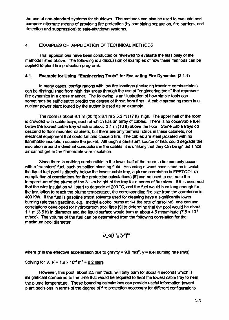
the use of non-standard systems for shutdown. The methods can also be used to evaluate andcompare alternate means of providing fire protection (by combining separation, fire barriers, anddetection and suppression) to safe-shutdown systems.
4. EXAMPLES OF APPLICATION OF TECHNICAL METHODS
Trial applications have been conducted or reviewed to evaluate the feasibility of themethods listed above. The following is a discussion of examples of how these methods can beapplied to plant fire protection programs.
4.1. Example for Using "Engineering Tools" for Evaluating Fire Dynamics (3.1.1)
In many cases, configurations with low fire loadings (including transient combustibles)can be distinguished from high risk areas through the use of "engineering tools" that representfire dynamics in a gross manner. The following is an illustration of how simple tools cansometimes be sufficient to predict the degree of threat from fires. A cable spreading room in anuclear power plant toured by the author is used as an example.
The room is about 6.1 m (20 ft) x 6.1 m x 5.2 m (17 ft) high. The upper half of the roomis crowded with cable trays, each of which has an array of cables. There is no observable fuelbelow the lowest cable tray which is about 3.1 m (10 ft) above the floor. Some cable trays dodescend to floor mounted cabinets, but there are only terminal strips in these cabinets, notelectrical equipment that could fail and cause a fire. The cables are steel jacketed with noflammable insulation outside the jacket. Although a persistent source of heat could degrade theinsulation around individual conductors in the cables, it is unlikely that they can be ignited sinceair cannot get to the flammable wire insulation.
Since there is nothing combustible in the lower half of the room, a fire can only occurwith a "transient" fuel, such as spilled cleaning fluid. Assuming a worst case situation in whichthe liquid fuel pool is directly below the lowest cable tray, a plume correlation in FPETOOL (acompilation of correlations for fire protection calculations) [8] can be used to estimate thetemperature of the plume at the 3.1 -m height of the tray for a series of fire sizes. If it is assumedthat the wire insulation will start to degrade at 200 °C, and the fuel would bum long enough forthe insulation to reach the plume temperature, the corresponding fire size from the correlation is400 KW. If the fuel is gasoline (most solvents used for cleaning have a significantly lowerburning rate than gasoline, e.g., methyl alcohol bums at 1/4 the rate of gasoline), one can usecorrelations developed for hydrocarbon pool fires [9] to determine that the pool would be about1.1m (3.5 ft) in diameter and the liquid surface would bum at about 4.5 mm/minute (7.5 x 10"5
m/sec). The volume of the fuel can be determined from the following correlation for themaximum pool diameter.
Dm.2[VW}m
where g' is the effective acceleration due to gravity = 9.8 m/s2, y = fuel burning rate (m/s)
Solving for V, V= 1.9 x 1O4 m3 = 0.2 liters
However, this pool, about 2.5 mm thick, will only bum for about 4 seconds which isinsignificant compared to the time that would be required to heat the lowest cable tray to nearthe plume temperature. These bounding calculations can provide useful information towardplant decisions in terms of the degree of fire protection necessary for different configurations
243
and thermal loads. The tools allow using some information representing the fire dynamics of theproblem, and can be used to prevent over-emphasis (or under-emphasis) that can occur whensuch considerations are omitted and the hazard from all fire areas are equally treated.
4.2. Examples for Using Reliability Methods (3.1.2)
Fire detectors in safety-related areas must be tested periodically, sometimes asfrequently as every 3 months in the U.S. Test intervals for all detectors are equally prescribedregardless of performance in codes of the National Fire Protection Association (NFPA), andincorporated into plant technical specifications. Test intervals established based onperformance, have been used in other testing programs in nuclear plants [3] and offeropportunities for cost optimization and a focused fire protection surveillance program.
The use of reliability engineering models supported by actual failure data for evaluatingappropriate tests intervals for fire detectors has been considered and implemented in a U.S.plant [10]. This plant used fire detector testing records covering a period of five years toestablish plant-specific fire detector failure rates. Three types of detectors were considered -ionization, heat, and photoelectric detectors. The surveillance records covered 3 years of semi-annual testing, followed by 2 years of annual testing. Based on the analysis of this performancedata, an alternative testing methodology was implemented by the utility by using 10-percentrotating sampling at an annual test interval, with provisions for expanding the sample populationif a decline in performance was observed.
More formal reliability methods have been used elsewhere [11] that illustrate thefeasibility and benefit of performance-based strategies for fire protection system surveillance.Based on a reliability model, detector failures were classified into random, test-generated, andtest-independent faults. Effectiveness of various test strategies for detecting failures was thenevaluated, and finally, the parameters of the reliability models (including the uncertainties) wereestimated through statistical techniques. These parameters were them included in the reliabilitymodel to determine an optimal test strategy. The results indicated that extending the testinterval from quarterly to annually, supplemented by daily self-verification and quarterlyinspection, would increase the reliability of the detectors and decrease testing costs.
4.3. Example for Using Fire Computer Codes Based on Zone Models (3.1.3)
Fire protection regulations [12] of the U.S. Nuclear Regulatory Commission (NRC)require that one train of systems necessary to achieve and maintain hot shutdown conditions befree of fire damage. The regulation provides three options for meeting this requirementincluding one that allows for separation of cables, equipment, and associated non-safety circuitsof redundant safe-shutdown trains by a horizontal distance of more than 6.1 m (20 ft) with nointervening combustible materials or fire hazards, in addition, fire detectors and an automaticsuppression system should be installed. Experience from the early 1980's indicated that someutilities in the U.S. found it difficult to implement this prescriptive requirement (it would be toocostly), and requested the U.S. NRC that they be exempted from this requirement. In almost allcases, some combination of low combustible loading, a high compartment ceiling, or negligibleintervening combustible was used as justification. Utilities indicated that in some casescompliance with the prescriptive requirement would require forced outages and cost up to $ 24million. The U.S. NRC approved several of the requests for exemptions based on thearguments provided.
Most of the arguments provided by the utilities were qualitative, although at least oneutility used correlations in FPETOOL [8] to quantitatively estimate the fire hazard. Since theearly 1980's, several fire models and computer codes have been developed that have beenused in PRAs and other applications. A study was conducted to evaluate the capability of the
244

following three fire models for developing insights regarding the 20-ft safe-separationrequirement: (1) FIVE - a compilation of fire correlations in worksheets for use in screening fireareas [7]; (2) COMPBRN Ille - a fire computer code developed for fast computations for use infire PRAs [13]; and (3) CFAST - a fire computer code developed mainly for use in modeling firesin buildings [14].
A representative PWR emergency switchgear room (ESGR) was used for the study.
Figure 1. Illustration of Critical Cable Locations in theRepresentative Emergency Switchgear Room
The room is 15.2 m (50 ft) x 9.1 m (30 ft) x 4.6 m (15 ft) high. The room contains the power andinstrumentation cables for the pumps and valves associated with motor-driven auxiliaryfeedwater trains, all three high-pressure injection trains, and both low-pressure injection trains.A simplified elevation of the ESGR room, illustrating critical cable locations, is shown in Figure 1.The power and instrumentation cables associated with safe-shutdown equipment are arrangedin separate divisions and are separated horizontally by a distance, D, in Tray B. The value of Dis varied in this evaluation. The analysis was conducted for different elevations of Tray B so thatit was either in the ceiling jet sublayer or in the hot gas layer for different cases.
The postulated ignition source is either a self-ignited cable (as a result of a fault) or cableignition as a result of a transient fire. Cable Tray A is considered to be the source. Although,most rooms will be isolated by the automatic closing of fire dampers and the shutdown of theventilation system, a small opening 2 m (6.5 ft) high x 0.2 m (0.7 ft) wide was assumed toprevent pressure buildup in the room and facilitate the use of the COMPBRN and CFASTcodes.
The ESGR contains smoke detectors and a manually actuated Halon system.Considering the fire initiating frequency and suppression (including fire brigade) probability, itcan be estimated that if equipment affecting redundant trains is not damaged within 1 hour, thenthe resulting core-damage frequency (CDF) for this scenario will be less than 1.2E-5 perreactor-year. This damage frequency and time is used as a measure for determining theadequacy of the safe separation distance.
The FIVE method predicts that an effective fire source intensity of about 6.5 MW isrequired to damage cables that are separated by 20 ft, and 3.5 MW if separated by 10 ft, forcables that are in the ceiling jet layer (see Table 1). The FIVE screening method does notdifferentiate between the various separation distances in the hot gas layer and only
245
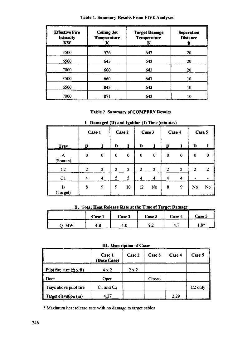
Table 1. Summary Results From FIVE Analyses
Effective FireIntensity
KW
3500
6500
7000
3500
6500
7000
Ceiling JetTemperature
K
526
643
660
660
843
871
Target DamageTemperature
K
643
643
643
643
643
643
SeparationDistance
ft
20
20
20
10
10
10
Table 2 Summary of COMPBRN Results
I. Damaged (D) and Ignition (I) Time (minutes)
Tray
A(Source)
C2
Cl
B(Target)
Case
D
0
2
4
8
1
I
0
2
4
9
Case 2
D
0
2
5
9
I
0
3
5
10
Case
D
0
2
4
12
3
I
0
2
4
No
Case
D
0
2
4
8
4
I
0
2
4
9
Case
D
0
2
_
No
5
I
0
2
_
No
II. Total Heat Release Rate at the Time of Target Damage
0, MW
Casel
4.8
Case 2
4.0
Case 3
8.2
Case 4
4.7
Case 5
1.8*
in . Description of Cases
Pilot fire size (ft x ft)
Door
Trays above pilot fire
Target elevation (m)
Casel(Base Case)
4x2
Open
ClandC2
4.27
Case 2
2 x 2
Case 3
Closed
Case 4
2.29
Case 5
C2only
Maximum heat release rate with no damage to target cables
246

conservatively estimates, based an adiabatic heating of the gas, the total energy releaseneeded to raise the average hot gas layer temperature to the threshold damage temperature.In the present case, the total energy needed is about 286 MJ, which is much less than 3150 MJcorresponding to the energy released from a 3.5 MW fire during a 15-minute period. Therefore,none of the cases pass the screening criteria if the target is the hot layer.
The COMPBRN analyses predict (see Table 2) that the effective fire intensity, capable ofdamaging redundant cables separated by 6.1 m (20 ft), is about 4 MW for the representativeconfiguration, and that damage occurs in about 12 minutes. The COMPBRN code alsopredicts that a cluster of two cable trays in one side of the room (Case 5 listed in Table 2) willresult in a peak burning rate of about 1.8 MW, which is not sufficient to damage cable traysseparated by 20 ft. The heat release rate predicted by COMPBRN for Case 2 is given in Fig. 2.
A modified version of the CFAST code, which accounts for radiation heat transfer to atarget, was utilized for this evaluation. The CFAST code requires input of the heat-release ratefor the fire source. Values of 1 MW, 2 MW, and 3 MW with a linear growth taking 1, 2, and 3minutes, respectively for the heat released rate were used for three cases. The hot layertemperature, the radiative and convective heat transfer calculated by CFAST, was used in atransient conduction model for a thin slab to estimate the target surface temperature. Figures 3,4, and 5 show the hot layer and cable surface temperatures for a 1, 2, and 3-MW fire as afunction of time. Considering the critical damage temperature of 643 K and the extrapolation ofthe result shown in Figs. 3, 4, and 5, a fire of more than 3 MW is required to damage the targetcables at a 20-ft separation in less than 1 hour, and a fire less than 2 MW will not damageredundant cables separated by less than 6.1 m (20 ft).
In order to understand the reason for the difference in the predictions of the CFAST andCOMPBRN codes, the availability of oxygen to support the burning rates predicted byCOMPBRN (see Figure 2) was examined. The CFAST code is capable of calculating theconcentration of various species of air and combustible products in the hot layer region,whereas COMPBRN does not account for oxygen depletion and possible starvation of the fire.Using burning rates predicted by COMPBRN, CFAST predicts that, at about 5 minutes, the hotgas layer descends to the level of the lowest burning tray and the concentration of oxygen in thehot layer is below 10 percent (ordinary air is 21 percent). Therefore, the heat release rate will
PWR ESQH 20-FT SEPARATION STUDY
COMPBRN AND CFAST COMBVWSON - CASE 2
0.0 2-0 4.0 6.0 8.0 10.0 12.0 14.0 16.0
Figure 2 Heat Release Rate Predicted by COMPBRN - Case 2
247

HOT LAYER TEMPERATURE -tr TARGET TEMPERATURE
550
3001500 2000 2500 3000 3500
TIME (sac)
Figure 3. CFAST Prediction of 1-MW Source Target and HotLayer Temperature
itu
300 2
• * - HOT LAYER TEMPERATURE -£r TARGET TEMPERATURE
500 1000 2500 30001500 2000
TIME (sec)
Figure 4. CFAST Prediction of 2-MW Source Targetand Hot Layer Temperature
3500
- • - HOT LAYER TEMPERATURE -A- TARGET TEMPERATURE
700
300500 1000 2SO0 30001500 2000
TIME (sac)
Figure 5. CFAST Prediction of 3-MW Source Targetand Hot Layer Temperature
3500
248

PWB ESGR 20-FT SEPARATION STUW
COMPBRN AND CFAST COMRVUSON-CASE 2
-
-
COMPBRN
CfifcST i
yS
/ y
r/ \
\0.0 2.0 4.0 6.0 8.0 10.0 12.0 14.0 16.0
TIME (mm)
Figure 6. Comparison of CFAST and COMPBRN Predictionof Hot Gas Layer Temperatures
not increase after 5 minutes because of oxygen depletion and the fire would eventually beextinguished when insufficient oxygen is available to support combustion. Accordingly, the peakheat-release rate for this specific case will be below 2 MW and the heat-release rate predictedby COMPBRN after 5 minutes is overly conservative.
Figure 6 shows a comparison of the results from the CFAST and COMPBRN codes forCase 2 (see Table 2 for case conditions). In this case, the heat release rate due to firepredicted by COMPBRN (Figure 2) is provided as input to the CFAST code for the comparisonanalysis. After the COMPBRN-predicted ignition of Tray C2 at 5 minutes and Tray B (the targettray) at 10 minutes, Figure 6 shows that the hot gas layer temperature predicted by COMPBRNis much higher than that predicted by CFAST. This may be due to the conservativeassumptions regarding heat losses from the hot layer in the COMPBRN code, however, thereason for this large difference in hot layer temperature was not examined further.
Based on the above results, it is concluded that if the maximum cluster of source cablesresults in a heat-release rate less than about 2 MW, then redundant cables will not be damaged,even if they are separated by less than 20 ft (e.g. 15 ft). The dominant factor for all the firemodels for predicting damage to cables that are separated by 20 ft is the effective intensity ofthe fire source, not the total combustible loading in the fire area. Uncertainties in the fireintensity will dominate other uncertainties, such as in calculating the thermal environment, forpredictions of cable damage.
The above study illustrates the capability of these fire computer codes to evaluatealternative approaches to the 20-ft separation criteria, although at different levels of resolution.The FIVE method is adequate for screening purposes but does not have sufficient resolution toaddress the problem in this evaluation if it is assumed the target is in the hot layer. The CFASTcode provides a better non-conservative estimate for this problem than the COMPBRN code.However, both COMPBRN and CFAST estimate that a fire of about 1.8 MW or less will notdamage redundant cables with 20-ft separation. This corresponds to a maximum cluster ofthree cable trays. Although the accuracy of these codes should be improved further, they canalready provide approximate results, with a reasonable degree of confidence, that are useful forinvestigating parameters of interest in fire protection, e.g. the 20-ft separation criteria.
249
4.4. Example for Using Delta-CDF Calculations (3.2.3)
In order to limit the amount of repairs to equipment for achieving safe shutdown in theevent of a fire, current fire regulations of the U.S. NRC require that a plant have the capability toreach cold shutdown conditions within 72 hours [12]. Experience from the early 1980's inimplementing this requirement indicates that some U.S. plants found it difficult (it would be toocostly) to meet this prescriptive requirement, and therefore requested the U.S. NRC that they beexempted from this requirement based on qualitative arguments that indicated that alternativesthat included the use of non-standard systems and repairs, and would require more than 72hours to reach cold shutdown, would provide an equivalent level of safety. These requests forexemptions based on qualitative arguments were accepted by the U.S. NRC.
Since the early 1980's methods, methods for fire PRAs have become available and canbe used to quantify, through delta-CDF calculations, the impact of using alternative methods forachieving the higher level safety objective. The following illustrates this method.
The LaSalle fire PRA analysis [15] for the fire area for the cable shaft room adjacent tothe Unit 2, Division 2, essential switchgear room was used for the purpose of this illustration. Itwas postulated1 that the fire area contains equipment associated with both trains of the ResidualHeat Removal (RHR) System, and that the fire damage is extensive and it will take more than72 hours to restore one RHR train. This study adopts the LaSalle PRA assumption that a smallfire anywhere in the fire subject area will cause the rapid formation of a hot gas layer thatcauses all critical cabling to fail. Prescriptive compliance with the 72-hour requirement wouldnecessitate that of one RHR train be removed from the fire area, or that it be protected. Analternative approach is postulated to include reestablishing the condenser (Power ConversionSystem - PCS) for long-term decay heat removal to allow sufficient time for the repair of onetrain of RHR shutdown cooling. This approach would take more than 72 hours to reach coldshutdown.
The LaSalle fire PRA used conservative assumptions and excluded credit for operatorrecover actions for modeling the subject fire area since it was a non-dominant contributor to thefire-induced CDF. Therefore a more detailed event tree (shown in Figure 7) was developed forthis example which included manual actions to recover PCS and RHR. The prescriptivecompliance case assumes one RHR train is removed from the fire area or otherwise protected.Therefore, a failure of the Containment Heat Removal (CHR) function requires additional RHRrandom failures. The estimated unavailability is CHR = 1.1E-1. The altemative case does notprotect the RHR system. All containment heat removal is assumed lost due to the fire, andCHR = 1.0. Operator actions to reestablish the condenser and to recover one train of RHR arecritical issues in this analysis. Detailed plant-specific human reliability analysis would berequired to accurately represent important operator actions and potential systems interactions.For illustrative purposes, conservative failure estimates were used for these restorations for thisstudy. The four sequences leading to core damage are quantified for both the prescriptive andaltemative approaches. The final result is given at the bottom of the Figure; it is ACDF = 8.0E-7.
The above example illustrates the PRA method and the feasibility of using ACDF as atool toward evaluating the safety equivalence of an alternative approach to a prescriptiverequirement. As is the case for this example, alternate approaches can be expected to requirereexamination of non-dominant sequences, and use of a finer level of modeling resolution tocredit certain operator recovery actions. The purpose of this example was not to only determinea bottom-line ACDF (in any case this analysis is not based on a real plant configuration or
1lt was necessary to assume some changes to the configuration of this fire area in order to allowdata from the LaSalle fire PRA to be used for this illustration. Therefore, this analysis does not model theLaSalle plant.
250
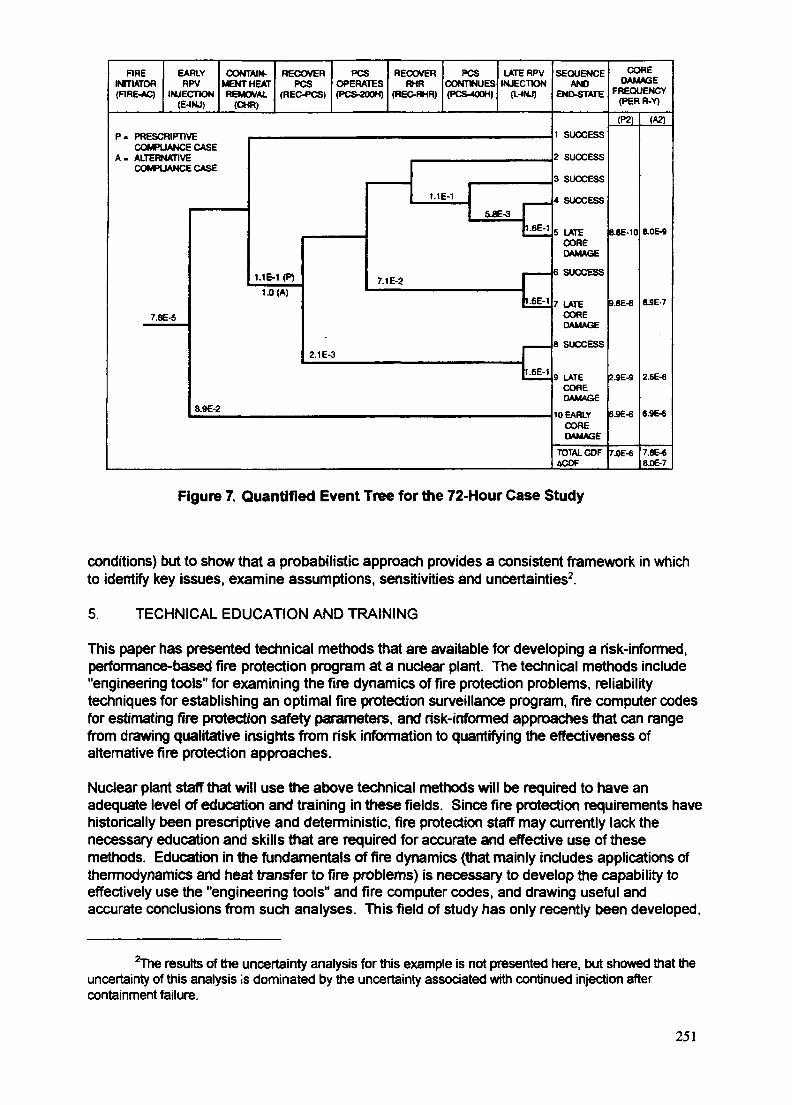
FIREINmATOR(FIRE-AC)
EARLYRPV
INJECTION(E-INJ)
CONTAIN-MENT HEATREMOVAL
(CHR)
RECOVERPCS
(REC-PCS)
PCSOPERATES(PCS-200H)
RECOVERRHR
(REC-RHR)
PCSCONTINUES(PCS-400H)
LATE RPVINJECTION
(L-(NJ)
P . PRESCRIPTIVECOMPLIANCE CASE
A . ALTERNATIVECOMPLIANCE CASE
7.8E-5
1.1E-1 (P)
1.0 (A)
1.1E-1
5.8E-3
7.1 E-2
I.6E-1
I.6E-1
2.1 E-3
8.9E-2
I.6E-1
SEQUENCEAND
END-STATE
1 SUCCESS
2 SUCCESS
3 SUCCESS
4 SUCCESS
5 LATECOREDAMAGE
6 SUCCESS
7 LATECOREDAMAGE
8 SUCCESS
9 LATECOREDAMAGE
10 EARLYCOREDAMAGE
TOTAL CDFACOF
COREDAMAGE
FREQUENCY(PERR-Y)
(P2)
B.8E-10
9.8E-8
2.9E-9
6SE-6
7.0E-6
(A2)
S.OE-9
8JE-7
2.6E-8
6.9E-6
7.8E-68.0E-7
Figure 7. Quantified Event Tree for the 72-Hour Case Study
conditions) but to show that a probabilistic approach provides a consistent framework in whichto identify key issues, examine assumptions, sensitivities and uncertainties2.
5. TECHNICAL EDUCATION AND TRAINING
This paper has presented technical methods that are available for developing a risk-informed,performance-based fire protection program at a nuclear plant. The technical methods include"engineering tools" for examining the fire dynamics of fire protection problems, reliabilitytechniques for establishing an optimal fire protection surveillance program, fire computer codesfor estimating fire protection safety parameters, and risk-informed approaches that can rangefrom drawing qualitative insights from risk information to quantifying the effectiveness ofalternative fire protection approaches.
Nuclear plant staff that will use the above technical methods will be required to have anadequate level of education and training in these fields. Since fire protection requirements havehistorically been prescriptive and deterministic, fire protection staff may currently lack thenecessary education and skills that are required for accurate and effective use of thesemethods. Education in the fundamentals of fire dynamics (that mainly includes applications ofthermodynamics and heat transfer to fire problems) is necessary to develop the capability toeffectively use the "engineering tools" and fire computer codes, and drawing useful andaccurate conclusions from such analyses. This field of study has only recently been developed,
2The results of the uncertainty analysis for this example is not presented here, but showed that theuncertainty of this analysis is dominated by the uncertainty associated with continued injection aftercontainment failure.
251

and there are only a few colleges in the U.S. that offer a curriculum that would provide thenecessary education. The knowledge and capability to conduct or understand fire PRAs is alsonormally not possessed by fire protection staff. Training in PRA techniques, including the basicsof probability and statistics, will be necessary in order to use PRA and reliability techniques fordeveloping risk-informed, performance-based fire protection programs.
6. CONCLUSION
Methods for modeling fires, and reliability and PRA analyses are currently available tosupport the initial development of a risk-informed, performance-based fire protection program.Some of these methods require the use of fire computer codes and fire PRAs which will requireadequate education and training of the fire protection staff that will use these methods.However, the initial development of a risk-informed, performance-based program does notnecessarily require extensive calculations using fire PRAs and models. In many cases, the useof simple performance-based analysis (e.g., "engineering tools" based on fundamentalprinciples of fire dynamics) or application of risk insights in a qualitative manner (e.g., foremergency lighting requirements) is sufficient to examine and implement alternativeapproaches.
Given the economic status of the nuclear power industry in many countries, including theU.S., the use of risk-informed, performance-based approaches for fire protection programs innuclear power plants should be implemented in phases. Initially, methods that do not require asignificant investment of resources (e.g. in research and training) should be implemented, andthe benefits from these applications should be assessed. Based on the assessment of theseinitial simple applications, the benefits of further investments and development of a risk-informed, performance-based fire program can be evaluated. A phased transition will allowplant resources to be focused for better protection, and the program to be more efficient withoutthe need for a large investment of resources.
ACKNOWLEDGEMENTS
The author wishes to thank Ali Azarm and Richard Travis at the Brookhaven NationalLaboratory, and Robert Levine formerly with the National Institute of Standards and Technologyin the United States for their significant contributions to the work presented in this paper.
REFERENCES
[1] U.S. NRC Program for Elimination of Requirements Marginal to Safety (Proc. of PublicWorkshop, Washington, B.C., USA, 1993), NUREG/CP-0129 (1993).
[2] U.S. NUCLEAR REGULATORY COMMISSION, Institutionalization of ContinuingProgram for Regulatory Improvement, SECY-94-090 (1994).
[3] DEY, M.K., Performance-Oriented And Risk-Based Regulation For Containment Testing,Nuclear Engineering and Design 166 (1996) 305-309, see also Primary Reactor-ContainmentLeakage Testing for Water-Cooled Power Reactors, Federal Register, 60 (1995) 49495.
[4] BUKOWSKI, R., A Review of International Fire Risk Prediction Methods, Proc. of Interflam93, The Fourth International Fire Science and Engineering Conference, InterscienceCommunications Limited, London (1993).
[5] BERTRAND, R et al., Studies of Fire Development - Development of FLAMME-SComputer Code, ICONE 5: Nuclear Advances Through Global Cooperation, Nice, France(1996).
[6] JONES, W.W., Progress Report On Fire Modeling and Validation, Proc. Thirteenth JointPanel Meeting Of The UJNR Panel on Fire Research and Safety, National Institute ofStandards and Technology (1996).
252

[7] ELECTRIC POWER RESEARCH INSTITUTE, Fire-Induced Vulnerability Evaluation(FIVE), EPRI TR-100370 (1992).
[8] DEAL, S., Technical Reference Guide for FPETOOL Version 3.2, National Institute ofStandards and Technology, NISTIR 5486 (1994).
[9] SOCIETY OF FIRE PROTECTION ENGINEERING, The SFPE Handbook of FireProtection Engineering, Second Edition, 3-201, 203.
[10] BRUCE, G.E., Performance Based Fire Detector Surveillance Testing - A Nuclear PlantApplication, Proc. of American Nuclear Society International Topical Meeting on Safety ofOperating Reactors, Seattle, Washington (1995).
[11] HOKSTAD, P., et al., A Reliability Model For Optimization of Schemes for Fire and GasDetectors, Reliability Engineering and System Safety, 47 (1995), 15-26.
[12] U.S. NUCLEAR REGULATORY COMMISSION, Fire Protection Program for OperatingNuclear Power Plants, Federal Register, 45 (1980), 76602.
[ 13] ELECTRIC POWER RESEARCH INSTITUTE, COMPBRN Hie: An Interactive ComputerCode for Fire Risk Analysis, EPRI NP-7282 (1991).
[14] PEACOCK, R.D., et al., CFAST, The Consolidated Model of Fire Growth and SmokeTransport, National Institute of Standards and Technology Technical Note 1299 (1993).
[15] U.S. NUCLEAR REGULATORY COMMISSION, Analysis of the LaSalle Unit 2 NuclearPower Plant: Risk Methods Integration and Evaluation Program (RMIEP), Internal FireAnalysis, NUREG/CR-4832, 9 (1993).
253
IAEA-SM-345/42Invited Paper
INDUSTRY PARTICIPATION IN THE DEVELOPMENT XA9847523OF A RISK-INFORMED, PERFORMANCE-BASED REGULATIONFOR FIRE PROTECTION AT US NUCLEAR POWER PLANTS
F.A. EMERSONNuclear Energy Institute,Washington, D.C.,United States of America
Abstract
The USNRC staff have recently been directed by the NRC Commissioners to evaluate quicklythe development of a risk-informed, performance-based fire protection regulation to replace thecurrent regulations. The US nuclear industry does not believe a new rule is necessary to increase firesafety, and believes that there are significant risks and potentially significant benefits depending onthe construction of the rule. However, the industry will actively work with NRC staff if rulemakingproceeds such that the risks are minimized and the benefits maximized. A Nuclear Energy Institute(NEI) Issue Task Force (ITF) has been established to guide the participation of industry in anyrulemaking activity. If rulemaking proceeds, a framework should be established for the evolution of afire protection rule from the current prescriptive basis to a risk-informed, performance-based rule.
1. INTRODUCTION
The resolution of generic fire protection regulatory issues at US nuclear plants isgenerally coordinated by the Nuclear Energy Institute (NEI). The Fire Protection WorkingGroup (FPWG), comprised of senior industry managers and chaired by a senior utilityexecutive, advises NEI and the industry on the resolution of these issues. [NOTE: The term"industry" refers generically to all US nuclear utilities.] Issue Task Forces of technicalexperts can be formed by NEI and the Working Group to carry out specific assignments whichbenefit the industry as a whole. Day to day coordination of generic issues between USNRCand utilities is carried out by NEI staff.
The US nuclear industry does not believe a new rule is necessary to increase firesafety, and believes that there can be significant problems or benefits depending on theconstruction of the rule. However, if the current NRC rulemaking activities proceed the USnuclear industry has a strong interest in working with the NRC to assure the effectiveness ofany new fire protection rule. With its extensive experience in implementing existing rules (10CFR 50.48 and 10 CFR 50 Appendix R) the industry has much to contribute to therulemaking process and much to gain from a rule that is more flexible and more easilyinterpreted and implemented.
The NRC plans to date are outlined in References [1] through [4]. If NRC rulemakingactivities continue, coordinated industry activities are expected to proceed in accordance withthe plan described below.
255

2. INDUSTRY PERSPECTIVES ON FIRE PROTECTION RULEMAKING
2.1. Background Information
Specific and detailed requirements for fire protection features and programs arecontained in Appendix R to 10 CFR 50. Section II, General Requirements, articulates thefollowing basic elements of the regulation:
• Establish a fire protection program• Perform a fire hazards analysis• Establish fire prevention features for those areas containing or presenting a fire
hazard to structures, systems and components (SSC) important to safety(specifically those SSC needed to achieve and maintain shutdown conditions)
• Establish alternative or dedicated safe shutdown capability in areas where fireprotection features cannot ensure safe shutdown capability.
The regulation is directly applicable to plants licensed prior to January 1, 1979, andwas regarded as a physical backfit for those plants (the backfit rule was not in effect at thetime). The same requirements (with the exception of III.G.3) were incorporated into NUREG-800, the NRC Standard Review Plan Section 9.5.1 (and hence the FSAR) for plants licensedafter this date, based on Branch Technical Position 9.5-1. Plants in the former category mustrequest exemptions, pursuant to 10 CFR 50.12, for any deviations from the prescriptiverequirements of Appendix R. (This exemption process has been utilized over 1200 times,making Appendix R the most widely exempted regulation pertaining to nuclear power.)Plants in the latter category may make changes to their fire protection features or programs inaccordance with the requirements of 10 CFR 50.59, without the need for the exemptionprocess or advance NRC review. Of course, many aspects of the fire protection program for"Appendix R" plants are subject to change through the § 50.59 process, except for the featuresthat were backfitted by the rule. Additionally, some plants have license conditions addressingfire protection features.
While the regulatory basis for fire protection has remained unchanged since 1981,there has been a significant evolution of NRC expectations with respect to compliance. Thesehave been articulated in a series of NRC Generic Letters, the most significant of which wasGeneric Letter 86-10 [5], [6]. Actual regulatory oversight has typically been a process ofNRC staff interpretations and inspections such that, in the industry view, there has beencontinuing difficulty in dealing with emerging issues. The process that has evolved is one ofmaking determinations based on utility-specific discussions with the working level NRC staff.
Licensees continue to devote significant resources to modifications to fire protectionfeatures and programs in an attempt to stay abreast of technical issues that arise and NRC staffinterpretations, examples of which include:
• Protection of safe shutdown pathways through installed hardware (barriers,suppression) versus credit for operator actions
• Acceptable fire tests• Determination of combustible materials• Consideration of electrical short circuits due to fire• Reactor coolant pump lube oil collection systems• Penetration seals.
256

A fundamental aspect of Appendix R is that there is often little connection between theactual fire hazard and the level of protection required. (The exemption provision provides theonly opportunity to bring actual fire hazards into consideration.) While performance of a firehazards analysis is mandated, the results of this analysis do not bear on the degree ofprotection or types of features provided. This was an explicit consideration of the originalrule due to difficulty in postulating (with the technology of the time) a "design basis" fire.
As a culmination of several years of efforts, and after receiving public input, NRCrecognized the need for revision to Appendix R. In July 1992, NRC issued SECY 92-263,"Staff Plans for Elimination of Requirements Marginal to Safety." [7] NRC recommendedinitiation of rulemaking to reduce regulatory burden without an adverse impact on safety bymaking three regulations less prescriptive and more performance oriented. Appendix R wasidentified as one of these regulations (Appendix J and 10 CFR 50.44 were the others). Byletter of August 31, 1992, the NRC Chairman informed the President of the United States ofNRC's plans to pursue rulemaking with regard to Appendix R. The NRC Regulatory ReviewGroup (RRG) was formed in 1993 to institutionalize a continuing program of regulatoryimprovement. This program identified an action plan for rulemaking to replace Appendix Rwith a performance-oriented, risk-based regulation. This plan identified that industry wouldpetition for rulemaking in this regard. SECY 94-090 [8] established Commission approval ofthe RRG program.
NEI (then the Nuclear Utility Management and Resources Council) moved forwardwith plans to prepare a petition for rulemaking. An ad hoc advisory committee was formed todevelop an Appendix S to 10 CFR 50 that would provide a performance-based alternative tothe prescriptive requirements of Appendix R. The petition was filed in February 1995.Following interactions with the Advisory Committee on Reactor Safeguards (ACRS) andinternal review, NRC stated at the Regulatory Information Conference in May 1996 that the"NEI petition does not meet objectives and framework established by the regulatoryimprovement program." In its response to SECY 96-134, the Commission denied the petitionand directed NRC staff to pursue a different approach for fire protection rulemaking, asoutlined later in this paper.
2.2. Industry Perspective on Current Regulations
The primary concern of the US nuclear plant fire protection community with respect tothe current regulations is the difficulty of consistent interpretation. Since many questionsarose in the 1980's about the interpretation of the regulations, the NRC published severalguidance documents culminating with Generic Letter 86-10 [5]. Nuclear utilities then usedthese interpretations to develop fire protection and safe shutdown programs which were laterapproved (on a plant-specific basis) by the NRC in the late 1980's.
These additional guidance documents have themselves been subject to varyinginterpretations between industry and the NRC. In some cases, industry representativesthought that they understood NRC intent at the time these guidance documents weredeveloped, only to find that current NRC staff interpret the guidance documents differently.One current example of such differing interpretations is the controversy over how manysimultaneous fire-induced spurious equipment actuations must be postulated in protecting asafe shutdown pathway. These varying interpretations can lead either to unintentionalviolations of the regulation by utilities who thought that they were in compliance, or perhaps
257

to expensive design changes that may or may not meet the intent of the rule. This is not adesirable situation either for industry or the NRC, and efforts are being made to deal with suchsituations as they arise.
While most industry professionals believe that compliance with the current regulationshas been difficult, considerable experience has been developed in applying the currentregulations to individual plants. Each plant's compliance with the regulations has beendeveloped over the years through the development of plant-specific fire plans, safe shutdownanalyses, NRC approval of formal exemptions to the regulations, and other plant-specificevaluations permitted by Generic Letter 86-10 and 10CFR 50.59. Except for differences ininterpretation of the regulations, most plants believe that their fire protection and safeshutdown programs are mature and that changes in the current regulations are not necessary toimprove compliance.
2.3. Performance and Risk Basis
NRC management actively encourages wider use of risk-informed and performance-based approaches. Since the initial promulgation of Appendix R there have been significantadvances in technology (e.g., fire modeling, risk assessment methods, fire equipmentmaterials and reliability) to support this premise, but it is generally felt that more refinement isnecessary before they are used to support a new rule.
A poorly implemented risk-informed or performance-based regulation will onlyexacerbate the existing problems with regulatory instability and inconsistency. In order forthis approach to succeed, it must contain clear objectives, explicit criteria, and a clear tiebetween fire hazard levels and adequate degrees of protection. Layering of risk andperformance requirements on existing requirements will not achieve the benefits desired usingthis approach.
Establishing useful and quantifiable performance goals relative to fire protection willrequire careful consideration. The occurrence of fires or of fire protection equipment failuresare rare, typically only one or two per year per reactor. Insight that comes from such a paucityof data will be unlikely to provide much flexibility. A better characterization could be the"hazard-based" or "risk-based" measures that can be developed for individual plant fire areas.In the case of fire protection, "performance" may be better characterized by predicting thelikelihood and consequences of a rare event, rather than statistically evaluating observedevents. Observable measures of performance are still important and can be measured to agreater degree with industry wide experience. Consequently, collecting and interpretingindustry fire events data would be an important element of performance based fire regulation.
Measurable fire protection performance means that the regulations, and the degree ofprotection required, should be tailored to the fire hazard in a particular plant location. Manyof the fire probabilistic safety assessments (PSAs) completed to date show that most fire areasare not risk significant, though some results with higher core damage frequencies have causedsome NRC concern that compliance with current fire protection regulations does notguarantee low risk levels. Industry firmly believes in the defense-in-depth philosophy,although for certain plant-specific conditions some elements may not be significant to safety.Thus, there could be either a reduction or an increase in fire protection indicated for aparticular fire ;area depending on the PSA results. In general, however, a lessening ofrequirements could be expected.
258
A key element is establishing a process to characterize the hazard and associateddegree of protection needed. The process for characterizing the potential fire environment isreferred to as "fire modeling," and along with PSA is the heart of a performance-basedapproach to fire protection.
Utilities and NRC have expended significant resources in the development of firePSAs. Many times, the PSA offers the most detailed model of fire scenarios and the mostuseful integrated view of fire protection. Efforts are underway to establish criteria for the useof PSA in risk-informed regulation. Building upon the fire PSA tools and results as well asthe pilot projects for risk-informed in-service testing and inspections, graded QA and riskbased technical specifications, seems a logical step in the development of improved fireprotection regulations.
2.4. Industry Perspective on New Fire Protection Rules
Because plant fire protection and safe shutdown programs are at a mature stage, mostfire protection professionals are reluctant to undertake a significant shift in the regulations toan untried risk and performance basis. Since there is little experience in the US withregulations based on risk and performance perspectives, industry fire protection professionalsare concerned that development of new rules will result in new requirements and new coststhat are not justified by improvements in safety. Therefore, a large segment of the US nuclearfire protection community would prefer to maintain the current regulations and methods ofcompliance rather than spend the time, effort, and expense required to develop and complywith a new rule. Since no new nuclear generation is planned, a new regulation may not becost beneficial.
In spite of this reluctance to proceed with fire protection rulemaking, there is arecognition of potential benefit from a new rule if the rule is constructed carefully. It would,for instance, be helpful to address emerging generic fire protection issues throughconsideration of risk significance and cost benefit, thus avoiding costly new requirementswith little safety improvement. It would be beneficial to address plant-specific issues throughconsideration of risk significance or importance using risk or effective fire modeling tools. Itcould be advantageous to be judged during an NRC inspection on the basis of a fairperformance standard rather than prescriptive requirements that may or may not be related toreal safety issues. Lastly, it would be of considerably easier to comply with a rule whichlends itself to consistent interpretation and compliance.
Given a choice, most industry fire protection professionals would prefer not to proceedwith rulemaking. Since there appears to be considerable NRC momentum toward proceedingwith fire protection rulemaking, most industry professionals would prefer to see a high degreeof industry involvement in any rulemaking activity with the goal of maximizing the benefitsand minimizing the problems noted above. NEI has recently requested completion of a surveyby all utilities which will provide a clear indication of support for and concerns withrulemaking. The results of the survey will be provided when this paper is presented at theSymposium.
259

3. INDUSTRY PARTICIPATION IN RULEMAKING
3.1. Industry Goals
If fire protection rulemaking proceeds, it is important to begin any discussion ofindustry contributions by clearly stating industry goals for any new fire protection rule:
1. Industry should be an integral part of any rulemaking process. The collectiveexperience of the regulated industry should be utilized throughout the rulemakingprocess. Industry contributions will assist the NRC in assuring clarity in the rule'slanguage and reflecting the perspective of plants that must implement the rule.
2. The rule should be measurable, inspectable. and enforceable. It should be muchsimpler to determine whether requirements embodied in the new regulation havebeen met than it is with the current regulations. This approach will help assureimproved regulatory stability, including the consistent implementation andenforcement of requirements throughout the industry. The development of simpleperformance criteria will help meet this goal.
3. The rule should have an option for continued compliance with existing regulations.Since many plants have many years' experience with the current rule and relativelyfewer years left in their operating lifetimes, there is no benefit from a regulationwhich forces backfits in plant fire protection programs. Any additional expensemay also decrease the economic viability of some nuclear units. Having an optionto continue with existing programs, while offering the flexibility for makingchanges to those plants that can benefit from them, seems to offer the mostpromise for regulatory compliance and cost-effective operation.
4. The new rule should offer the capability for evaluating new issues based on safetysignificance and cost benefit. The new rule should focus on realistic, credible fireinitiator and propagation threats and responding to them through good fireprotection practices (prevention, detection, and suppression). Some regulatoryinterpretations of the existing rule require extensive engineering analysis and/ormodifications to address very low likelihood fire damage scenarios. The ability toemploy a measurable risk criterion should help plant staff focus on the most safetysignificant fire protection issues. Cost benefit should be considered in conjunctionwith safety significance in evaluating new issues.
3.2. Industry Contributions to Rulemaking
In the event that rulemaking proceeds, industry has formed an NEI Issue Task Force(ITF) to achieve the following:
• Develop industry goals and performance criteria for supporting a risk-informed,performance-based fire protection rule
• Develop a process for achieving the goals and performance criteria• Review existing technology and develop recommendations for research or projects
needed to support rulemaking
260
• Manage a pilot program for assessing the value of risk-informed performance-based approaches to real fire protection issues
• Support technical interactions between NRC and industry relative to each of theabove activities.
This ITF includes expertise in the areas of fire protection, PSA, plant systems,engineering, fire research (EPRI), regulation, and nuclear insurance. Its first meeting was inSeptember, 1997.
3.3. Industry Position
Based upon the results of a comprehensive survey of U.S. nuclear utilities, the industryhas the following positions with respect to the current fire protection rulemaking effort:
•A new rule is not desired, nor is it required to assure or improve safety: Utilities haveestablished safe fire protection and safe shutdown programs under the currentregulation. Existing NRC and industry processes have generally been effective inaddressing emerging fire protection issues. It is important to preserve the option ofcompliance with the current rule. Rebaselining existing plant fire protectionprograms to a new rule would be burdensome, and the safety benefit is not clear.
•Industry will participate extensively if rulemaking proceeds: The fact of 100% utilityresponse to the survey indicates the importance of rulemaking to the industry, whichhas formed an NEI Issue Task Force to guide industry participation in anyrulemaking activity. The industry has many years of experience complying with thecurrent rule, and this experience should be used in making any new rule effective.Industry has projects underway which may be used to support a rulemaking effort,perhaps in cooperation with the NRC.
•The rulemaking schedule must allow adequate time for completion of supportelements: The four pilot Fire Protection Functional Inspections and the IPEEEsshould be completed to determine if important new safety issues resulting from theseevaluations support the development of a new rule. In addition, the activities of theNational Fire Protection Association (NFPA) to develop a new performance-basedconsensus standard for nuclear plant fire protection programs should be considered inrule development, even if the final standard is not complete. Lastly, given theindustry's long experience with the exemptions developed to date, and the extent towhich these are woven into a plant's licensing basis, any new rule attempting toenvelope or supersede them should be carefully considered.
•The use of risk and performance bases has promise: Whether or not rulemakingproceeds, industry sees benefit from the further development of risk and performancetools to support the fire protection regulatory environment. If rulemaking proceeds,it is important to emplace a framework for the further development of these tools; inthe absence of rulemaking these tools should be increasingly developed and usedwithin the context of the existing exemption process.
Subsequent steps to support the rulemaking activity will be determined as informationabout NRC plans unfolds and the responsibilities outlined above are carried out. The NEIIssue Task Force will work with NRC staff as necessary to maintain the NRC's schedule forrulemaking. Industry generally expects to evaluate risk-informed, performance-basedapproaches to fire protection through practical examples as rulemaking proceeds. This
261
approach should help focus any needed research or development activities on those areaswhere current technology is not adequate, and help assure the final usefulness of the rulewhile it is still being developed.
REFERENCES
[1] SECY 96-134, "Options for Pursuing Regulatory Improvement in Fire ProtectionRegulations for Nuclear Power Plants," USNRC (June 21, 1996).
[2] Staff Requirements Memorandum (SRM) associated with SECY 96-134, USNRC(October 2, 1996).
[3] SECY 9'M27, "Development of a Risk-Informed, Performance-Based Regulation forFire Protection at Nuclear Power Plants," USNRC (June 19, 1997).
[4] SRM associated with SECY 97-127, USNRC (September 11,1997).[5] Generic Letter 86-10, "Interpretation of Fire Protection Requirements," USNRC (April
24, 1986).[6] Generic Letter 86-10, Supplement 1, "Fire Endurance Test Acceptance Criteria for
Fire Barrier Systems Used to Separate Redundant Safe Shutdown Trains Within theSame Fire Area," USNRC (March 25,1994).
[7] SECY 92-263, "Staff Plans for Elimination of Requirements Marginal to Safety,"USNRC (July 24,1992).
[8] SECY 94-090, "Institutionalization of Continuous Program for RegulatoryImprovement," USNRC (March 31,1994).
262

IAEA-SM-345/13
РЕГУЛИРУЮЩАЯ ДЕЯТЕЛЬНОСТЬ В ОБЛАСТИ ПОЖАРНОЙБЕЗОПАСНОСТИ АЭС В РОССИЙСКОЙ ФЕДЕРАЦИИ:ЗАКОНОДАТЕЛЬНАЯ БАЗА И ОПЫТ ЛИЦЕНЗИРОВАНИЯ
В.И. ПОГОРЕЛОВГосатомнадзор России, ХА9847524Москва, Российская Федерация
Abstract-Аннотация
REGULATORY ACTIVITIES IN THE FIELD OF FIRE SAFETY AT NUCLEAR POWERPLANTS IN THE RUSSIAN FEDERATION: LEGISLATIVE INFRASTRUCTURE ANDLICENSING EXPERIENCE.
This paper discusses regulation of fire safety at nuclear power plants in Russia,including issues relating to the legislative infrastructure and licensing activities. Theinteraction of regulatory bodies in Russia (Gosatomnadzor and the State Fire Fighting Serviceof the Russian Ministry of Internal Affairs) on the issue of fire safety at nuclear power plants isdiscussed in detail. The legislative infrastructure for regulation of fire safety at nuclear powerplants is described and ways of improving it are discussed, as well as the development of anew fire protection approach, fire protection programmes with acceptability criteria, andmethodologies for analysing the effect of fires on nuclear power plant safety. The process fordetecting and eliminating faults in the regulation and implementation of fire safety measures atnuclear power plants is also described. In addition, we take a new look at the activities ofGosatomnadzor - licensing, including fire safety at nuclear power plants.
РЕГУЛИРУЮЩАЯ ДЕЯТЕЛЬНОСТЬ В ОБЛАСТИ ПОЖАРНОЙ БЕЗОПАСНОСТИАЭС В РОССИЙСКОЙ ФЕДЕРАЦИИ: ЗАКОНОДАТЕЛЬНАЯ БАЗА И ОПЫТЛИЦЕНЗИРОВАНИЯ
Данный доклад раскрывает вопросы регулирования пожарной безопасности (ПБ) наАЭС России, включая вопросы законодательной базы и лицензионную деятельность. Подробноизложены вопросы взаимодействия регулирующих органов России - Госатомнадзора России(ГАН РФ) и Государственной противопожарной службы Министерства внутренних дел России(ГПС МВД РФ) по вопросам ПБ на АЭС. Представлена законодательная база в областирегулирования ПБ на АЭС, излагаются вопросы ее совершенствования, разработки новойконцепции по противопожарной защите, программ противопожарной защиты с критериямиприемлемости, а также методик по выполнению анализа влияния пожаров на безопасностьАЭС. Изложен также процесс выявления недостатков и их устранения в системе регулированияи обеспечения ПБ АЭС. Представлен также новый вид деятельности ГАН РФ -лицензирование, включая вопросы ПБ АЭС.
1. ОБЩАЯ ЧАСТЬ
1.1. Организация и регулирование противопожарной безопасности АЭСгосударственными органами России.
Современное состояние и развитие атомной энергетики в России неразрывносвязаны с чернобыльской аварией. После первой тяжелой аварии на атомнойэлектростанции "Три МАЙЛ Айленд-2" в США (1979 г.) во многих странах мира,развивающих атомную энергетику, началось переосмысление подходов к обеспечениюбезопасности атомных электростанций. К сожалению в Советском Союзе эта работапроводилась недостаточно интенсивно и только после чернобыльской аварии
263

изменился концептуальный подход к обеспечению ПБ. Уже в 1988 г. была законченаразработка нового регулирующего документа - "Общие положения обеспечениябезопасности АЭС" (ОПБ-88), определившего на тот период концепцию безопасностиатомных станций.
Одновременно с внедрением концепции безопасности АЭС в Россиисущественные изменения произошли и в подходах к надзору и регулированию ПБ наАЭС. Усовершенствовалось государственное нормирование в области обеспечения ПБпутем установления норм, правил, руководящих, распорядительных и иныхдокументов. Совершенствовалась разрешительная и инспекционная деятельность.
В настоящее время на ГАН РФ возложены функции не только осуществлениянадзора , но и регулированиябезопасности (включая ПБ) на АЭС, а также во всей ядерной отрасли, включая
транспорт ядерных материалов и предприятия топливного цикла.Законодательство Российской Федерации о пожарной безопасности АЭС
основывается на Конституции РФ и включает в себя Федеральные законы "Обиспользовании атомной энергии"( 1995г.) и "О пожарной безопасности" (1994г.).
Важным условием обеспечения ПБ на АЭС является выполнение требованийнорм и правил по данному направлению, хотя пожарная защита действующих АЭСРоссии, которые были введены в эксплуатацию с 1971 по 1994 годы., проектироваласьи строилась по общепромьппленным нормам и правилам и не учитывалась спецификавлияния пожара на состояние ядерной и радиационной безопасности АЭС. Позже былразработан и введен ряд документов, основанных на требованиях ОПБ-88,регламентирующих проведение анализа безопасности при возникновении пожаров наАЭС.
Законом "Об использовании атомной энергии" определена компетенцияФедеральных органов исполнительной власти, организаций и предприятий по вопросаморганизации и регулирования ПБ на АЭС, а именно:
- обеспечение и контроль за ПБ на АЭС возложен на эксплуатирующиеорганизации (Минатом России);
- государственное регулирование и надзор за ядерной и радиационнойбезопасностью на АЭС возложены на ГАН РФ;
- государственное регулирование и пожарный надзор за соблюдением на АЭСтребований ПБ возложены на МВД РФ.
Основой регулирования государственными органами вопросов ПБ на АЭС вРоссийской Федерации является разрешительная деятельность (лицензирование,контроль, санкции).
В 1997 году Правительством РФ было введено в действие "Положение олицензировании деятельности в области использования атомной энергии", котороеустанавливает для ГАН РФ порядок и условия лицензирования деятельностиэксплуатирующих организаций АЭС. Этот документ является для ГАН РФосновополагающим, в соответствии с которым ГАН РФ в настоящее времяпересматривает (наработанный ранее) пакет руководящих документов по вопросамлицензирования в области использования атомной энергии.Со второй половины 1997года ГАН РФ выдает эксплуатирующим организациям лизензии на вид деятельности(взамен временных разрешений). Аналогичное "Положение..." введено в 1996 году и всистеме МВД РФ.
В целях взаимодействия и разграничения компетенций в области надзора заобеспечением ПБ ядерно- и радиационно-опасных объектов (в первую очередь АЭС)между ГАН РФ и ГПС МВД РФ было заключено (1994г.) соответствующее соглашение.Основными принципами взаимодействия являются:
264

- выработка единых позиций и взаимное согласование решений в областиобеспечения ПБ;
- проведение совместных мероприятий по совершенствованию требованийпротивопожарных норм и правил.
В указанном соглашении также определены основные направлениявзаимодействия, в частности:
- разработка законодательных и иных нормативных актов по проблемам ПБядерно- и радиационно-опасных объектов;
- организация и проведение научных исследований в областисовершенствования требований ПБ;
- изучение, анализ пожаров и разработка на этой основе предложений повнесению изменений и дополнений в нормативную документацию;
- проведение совместных проверок деятельности проектных организаций,ядерно- и радиационно-опасных объектов на всех этапах жизненного цикла и пр.
В этом же документе разграничены полномочия сторон следующим образром:а) ГАН РФ:- утверждает нормы и правила по безопасности при использовании атомной
энергии (по согласованию с ГПС МВД РФ);- проводит экспертизу проектных и иных материалов и дает оценку
достаточности принятых решений для обеспечения ядерной и радиационнойбезопасности в случае пожара;
- выдает лицензию на эксплуатацию объектов, а также разрешение на пускблоков после проведения плановых ремонтов (с учетом мнения органов ГПС МВД РФ)и пр.
б) ГПС МВД РФ:- утверждает нормы и правила по ПБ для ядерно- и радиационно-опасных
объектов (по согласованию с ГАН РФ), содержащие требования ПБ;- осуществляет государственный надзор за соблюдением на вышеуказанных
объектах требований норм и правил в области ПБ;- участвует в работе комиссий по приемке в эксплуатацию объектов и систем
противопожарной защиты, включая системы обеспечивающие безопасность;- ведет учет пожаров и информирует ГАН РФ о противопожарном состоянии
объектов и результатов инспектирования и пр.Данное соглашение между ГАН РФ и МВД РФ в настоящее время выполняется
обеими сторонами.
1.2.Нормативно-техническое обеспечение противопожарной защиты АЭС.
Важным условием обеспечения ПБ на АЭС в значительной степени являетсявыполнение эксплуатирующими организациями Минатома России требований норм иправил в данной области.
Противопожарная защита действующих АЭС России, как указывалось выше,проектировалась и строилась по общепромышленным нормам и правилам, когда еще небыло отдельных нормативов по ПБ.
В 1985 году было введено "Типовое содержание технического обоснованияатомных станций" (ТС ТОБ АС-85), которое требует проведения анализа безопасностипри пожарах в помещениях АЭС с учетом выхода из строя всех находящихся в нихэлементов или каналов безопасности.
В 1988 году были введены "Противопожарные нормы проектирования АЭС"(ВСН 01-87).
265

После Бвода ОПБ-88 документы, содержащие требования к проектированию истроительству противопожарной защиты АЭС, не пересматривались и вновь невыпускались, за исключением "Правил пожарной безопасности при эксплуатацииАЭС" (ППБ АС-95), которые были введены в 1995 году Минатомом России.
Таким образом, назрела необходимость создания нового пакета нормативныхдокументов по регулированию и надзору за противопожарной защитой действующих ивновь строящихся АЭС, в том числе, с использованием как отечественного, так изарубежного опыта детерминистского и вероятностного подходов к анализу ПБ наАЭС.
Намечены пути реализации данной проблемы. В частности, ГАН РФ решениемколлегии в 1996 году обязал МВД РФ (при участии ГАН РФ) разработать, с учетомнакопленного зарубежного опыта, концепцию противопожарной защиты АЭС, воснову которой должны быть заложены принципы безопасного останова,гарантированного расхолаживания реакторной установки (РУ) и обеспечениялокализации и контроля радиоактивных выбросов в окружающую среду. Основная цельконцепции - разработка отраслевого нормативного документа, учитывающегонакопленный российский и международный опыт и, в концептуальном виде,излагающего современные методы и подходы к вопросам ПБ АЭС. Концепция будетсодержать более высокие и современные требования к вопросам ПБ АЭС и, в первуюочередь, к анализу возможности безопасного останова РУ в случае пожара. Такойанализ будет заключаться в том, чтобы документально обосновать достаточностьпротивопожарной защиты для безопасности АЭС.
Концепция противопожарной защиты на АЭС России будет учитыватьтребования выпущенных ранее нормативных документов, а также будет содержатьследующие основные положения:
- требования к вновь разрабатываемым нормативным документам пообеспечению ПБ;
- требования по объему глубокоэшелонированной пожарной защиты АЭС;требованию по проведению анализа возможности безопасного останова
энергоблока в случае пожара во всех режимах эксплуатации;требования по разработке всеобъемлющей программы противопожарной
защиты для каждой АЭС;- требования к системам резервного управления и расхолаживания;- требования к системам обнаружения и тушения пожаров;- требования к обучению и тренировкам персонала и пр.В качестве исходных материалов используются документы МАГАТЭ, а также
документ Министерства энергетики США "Методология по оценке пожарнойбезопасности на АЭС с ВВЭР и РБМК (RCREM)".
В рамках разрабатываемой концепции эксплуатирующими организациямиразрабатываются программы противопожарной защиты по каждой АЭС. Задачапрограмм противопожарной защиты заключается в том, чтобы гарантироватьвозможность остановки реактора и поддержания его в безопасном состоянии останова,а также возможность сокращения до минимума утечки радиоактивных выбросов вокружающую среду в случае возникновения пожара.
Эти программы включают в себя комплекс мероприятий, охватывающийкомпоненты, процедуры и персонал, необходимые для осуществления всехмероприятий противопожарной защиты.
Программы противопожарной защиты будут удовлетворять следующимосновным критериям приемлемости:
266
- сооружения, системы и компоненты, существенные для безопасности будутпроектироваться, конструироваться и размещаться с таким расчетом, чтобы свести кминимуму вероятность пожаров и взрывов, а также возмещенный ущерб от них, непоступаясь при этом другими требованиями в области безопасности;
- эксплуатация систем обнаружения пожара и противопожарной защиты, а такжеадминистративный контроль будут направлены на защиту конструкций, систем икомпонентов реактора, связанных с обеспечением безопасности;
- конструкции, системы и компоненты, связанные с обеспечением ПБ будутгарантировать их способность выполнять предусмотренные для них функции;
- персонал АЭС будет соответствующим образом подготовлен в частиобеспечения ПБ.
Эксплуатирующим организациям предложено также разработать методикувыполнения анализа влияния пожаров и их последствий на безопасный останов РУ, аМинатому России пересмотреть до 2000 года действующую нормативную базу всоответствии с указанной концепцией. Главная задача методик заключается впроведении анализа противопожарной защиты для безопасности АЭС.
Кроме того распорядительным документом по Минатому РФ предписаноэксплуатирующим организациям выполнить анализ состояния ПБ для каждого блокаАЭС (на основе определения риска возможной тяжелой аварии) и по результатампроведенного анализа разработать соответствующие мероприятия по повышениюсостояния ПБ на АЭС. Такой анализ уже выполнен по блоку 3 Балаковской АЭС(ВВЭР-1000) и (при финансовой поддержке Министерства энергетики США) по блоку3 Смоленской АЭС (РБМК-1000).
В соответствии с "Положением о лицензировании в области использованияатомной энергии" эксплуатирующими организациями направляются в ГАН РФ, всоставе представляемых документов для получения лицензий на эксплуатацию блоковАЭС, отчеты по противопожарной защите с анализом влияния пожаров на выполнениефункций безопасности и с информацией по реализации мероприятий по устранениюнедостатков, выявленных при анализе.
В приложении 1 приведена структура законодательной базы и нормативно-правового обеспечения в области регулирования пожарной безопасности АЭС России,а в приложении 2 приведен перечень основной нормативной документации ГАН РФ,используемой при надзоре и регулировании вопросов ПБ на АЭС.
1.3. Процесс выявления регулирующими органами недостатков в системеобеспечения противопожарной безопасности.
Выявление недостатков в системе обеспечения ПБ на АЭС ведетсярегулирующими органами на всех жизненных этапах АЭС. В частности, ГАН РФ,выполняя свои регулирующие функции, проводит (перед выдачей лицензии)экспертизу материалов обосновывающих ядерную, радиационную и пожарнуюбезопасность. Особое внимание при этом уделяется проектным материалам, в которыхзакладываются основы ПБ. Экспертное заключение по рассматриваемым материаламявляется основой для составления условий действия лицензии на вид деятельности,куда входят также требования ГАН РФ об устранении выявленных недостатков вобласти ПБ.
Основным документом, которым в настоящее время руководствуется ГАН РФпри выявлении недостатков в системе обеспечения ПБ на АЭС и оценке влиянияпожара на выполнение функций безопасности является "Техническое обоснованиебезопасности АЭС" (ТОБ АС), имеющий разделы по анализу воздействия пожара натехнологическое оборудование и системы безопасности.
267
Непосредственно на АЭС региональными органами ГАН РФ вьщаютсяпоэтапные разрешения на проведение ремонтных работ, работ по модернизацииоборудования и систем и пр., при которых ГАН РФ выставляются условия кэксплуатирующим организациям об устранении в определенный срок выявленных(имеющихся) отступлений от норм и правил по обеспечению ПБ на АЭС.
Другим видом выявления недостатков в области обеспечения ПБ АЭС являютсяинспекции (комплексные, целевые и оперативные) государственных регулирующихорганов (ГАН РФ и ГПС МВД РФ). В программы таких инспекций включаютсявопросы проверки выполнения эксплуатирующими организациями требований поналичию документов об организации противопожарной защиты, подготовки персоналаи выполнению противопожарных мероприятий.
По результатам выявленных нарушений требований нормативной документациирегулирующими органами вьщаются руководителям АЭС предписывающие документыдля устранения недостатков в области обеспечения ПБ.
/. 4. Опыт лицензирования АЭС.Создание и реализация разрешительной системы при использовании атомной
энергии является одним из главных направлений деятельности ГАН РФ. Становлениеразрешительной деятельности ГАН РФ осуществлялось в условиях отсутствия вРоссии соответствующего законодательства об использовании атомной энергии.
При создании разрешительной системы ГАН РФ опирался на:- полномочия, предоставленные ГАН РФ Президентом Российской Федерации
по выдаче разрешений на виды деятельности;- перечень видов деятельности, на которые субъекты предринимательской
деятельности и предприятия, независимо от форм собственности, должны получатьразрешения (лицензии).
Перечень видов деятельности включает:- строительство, ввод в эксплуатацию, эксплуатацию, реконструкцию (включая
модернизацию и ремонт в течение срока службы), снятие с эксплуатации ядерно- ирадиационно-опасных объектов;
- производство, транспортирование, переработку, хранение, захоронение ииспользование ядерных материалов, радиоактивных веществ и изделий на их основе;
- хранение, переработку, транспортирование, утилизацию и захоронениерадиоактивных отходов.
Первым шагом по созданию разрешительной системы со стороны ГАН РФ быларазработка и введение в действие "Положения о порядке выдачи временныхразрешений на эксплуатацию блоков атомных станций" (1993г.).
В 1994 году было разработано и введено в действие "Положение о порядкевыдачи временных разрешений ГАН РФ на строительство блоков атомных станцийгражданского назначения" и ряд других руководящих и методических документов поорганизации и проведению экспертизы. Данный документ устанавливает порядокподачи заявки со стороны эксплуатирующей организации в ГАН РФ, требования кобъему документации по обоснованию безопасности, процедуре рассмотренияматериалов и Еыдачи разрешения на эксплуатацию.
Процедурными документами ГАН РФ предусмотрено, что при выдачевременных разрешений на строительство и эксплуатацию блоков АЭС проводится ихоценка безопасности (включая вопросы ПБ), которая выполняется путем анализасоответствующих обосновывающих документов и проведением, в случаенеобходимости, инспекций как самого блока АЭС, так и предприятия, претендующегона роль эксплуатирующей организации.
268
Порядок осуществления регулирующей деятельности ГАН РФ при проведениивладельцем модернизации АЭС (включая вопросы обеспечения ПБ) аналогиченвышеописанным процедурам с той лишь разницей, что решение владельца опроведении модернизации сначала согласовывается с ГАН РФ и только послеразработки мероприятий по реализации соответствующего технического решения,разработки проектно-конструкторской и технологической документации, изготовлениясоответствующего оборудования, выполнения необходимых строительно-монтажных ипусконаладочных работ на энергоблоке АЭС, корректировке эксплуатационнойдокументации - ГАН РФ выдает разрешение владельцу на ввод энергоблока АЭС вэксплуатацию.
При проведении анализа документов, обосновывающих ядерную, радиационнуюи пожарную безопасность ГАН РФ опирается на поддержку созданного при ГАН РФнаучно-технического центра по ядерной и радиационной безопасности (НТЦ ЯРБ), накототрый руководящими документами ГАН РФ возложена обязанность поорганизации и проведению экспертиз безопасности ядерно- и радиационно-опасныхобъектов, в том числе с привлечением внешних специалистов и организаций.
Первая заявка на получение разрешения на эксплуатацию блока 3Смоленской АЭС по указанной процедуре поступила в ГАН РФ от эксплуатирующейорганизации концерна "Росэнергоатом" в конце 1993 г. После рассмотренияматериалов в январе 1995 г. ГАН РФ выдал разрешение на эксплуатацию блока. Внастоящее время выданы разрешения на эксплуатацию 10 блокам АЭС, а также ведетсярассмотрение еще ряда заявок от эксплуатирующих организаций.
Случаев приостановки со стороны ГАН РФ действия разрешений наэксплуатацию блоков АЭС по причине, связанной с обеспечением ПБ, не было.Региональными структурами ГАН РФ и ГПС МВД РФ многократноприостанавливались работы и эксплуатация различных помещений и оборудования,находящегося в пожароугрожаемом состоянии. Например, только в 1996 годугосударственными регулирующими органами была приостановлена работа и запрещенаэксплуатация помещений или оборудования (изымались разрешения) в 995 различныхслучаях.
3. ЗАКЛЮЧЕНИЕ
Несмотря на существующие в Российской Федерации и атомной отрасли, в томчисле, экономических трудностей государственными регулирующими органами иэксплуатирующими организациями Минатома России выполняется значительнаяработа по совершенствованию регулирующей деятельности и законодательной базы вобласти обеспечения ПБ АЭС.
Федеральный закон "Об использовании атомной энергии" поставил перед ГАНРФ дополнительные задачи по систематизации и развитию процедур, связанных сразрешительной деятельностью, совершенствованию нормативной базы, включаявопросы обеспечения ПБ на АЭС, что, по мнению ГАН РФ, должно положительнымобразом сказаться на повышении состояния безопасности АЭС России.
269

Приложение 1
Законодательная база и нормативно-правовое обеспечение в областирегулирования пожарной безопасности АЭС России
КОНСТИТУЦИЯ РОССИИ
£Федеральный закон "Обиспользовании атомной
энергии"
Федеральный закон "Опожарной безопасности"
Обеспечение и контрольпожарной безопасности
Эксплуатирующиеорганизации АЭС
Регулирование и надзорза ядерной и
радиационнойбезопасности АЭС
Госатомнадзор России
Регулирование, надзор итушение пожаров на АЭС
Государственная противо-пожарная служба МВДРоссии
Лицензирование Соглашениео взаимодействии
НТД по вопросампожарной безопасности
АЭС
НТД по регулированию инадзору за ядерной и
радиационнойбезопасностью АЭС
безопасности в НТД попожарной
Российской Федерации
270
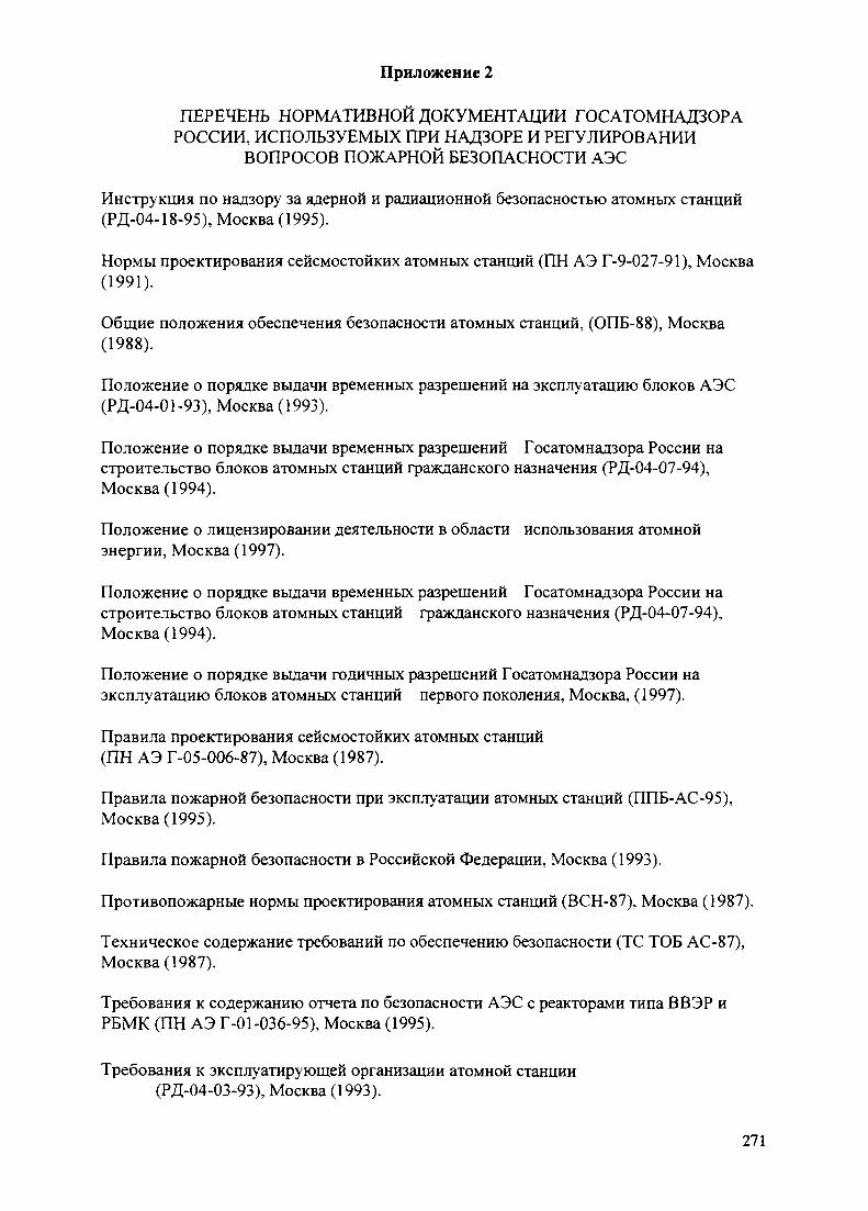
Приложение 2
ПЕРЕЧЕНЬ НОРМАТИВНОЙ ДОКУМЕНТАЦИИ ГОСАТОМНАДЗОРАРОССИИ, ИСПОЛЬЗУЕМЫХ ПРИ НАДЗОРЕ И РЕГУЛИРОВАНИИ
ВОПРОСОВ ПОЖАРНОЙ БЕЗОПАСНОСТИ АЭС
Инструкция по надзору за ядерной и радиационной безопасностью атомных станций(РД-04-18-95), Москва (1995).
Нормы проектирования сейсмостойких атомных станций (ПН АЭ Г-9-027-91), Москва(1991).
Общие положения обеспечения безопасности атомных станций, (ОПБ-88), Москва(1988).
Положение о порядке выдачи временных разрешений на эксплуатацию блоков АЭС(РД-04-01-93), Москва (1993).
Положение о порядке выдачи временных разрешений Госатомнадзора России настроительство блоков атомных станций гражданского назначения (РД-04-07-94),Москва (1994).
Положение о лицензировании деятельности в области использования атомнойэнергии, Москва (1997).
Положение о порядке выдачи временных разрешений Госатомнадзора России настроительство блоков атомных станций гражданского назначения (РД-04-07-94),Москва (1994).
Положение о порядке выдачи годичных разрешений Госатомнадзора России наэксплуатацию блоков атомных станций первого поколения, Москва, (1997).
Правила проектирования сейсмостойких атомных станций(ПН АЭ Г-05-006-87), Москва (1987).
Правила пожарной безопасности при эксплуатации атомных станций (ППБ-АС-95),Москва (1995).
Правила пожарной безопасности в Российской Федерации, Москва (1993).
Противопожарные нормы проектирования атомных станций (ВСН-87), Москва (1987).
Техническое содержание требований по обеспечению безопасности (ТС ТОБ АС-87),Москва (1987).
Требования к содержанию отчета по безопасности АЭС с реакторами типа ВВЭР иРБМК (ПН АЭ Г-01-036-95), Москва (1995).
Требования к эксплуатирующей организации атомной станции(РД-04-03-93), Москва (1993).
271

Федеральный закон об использовании атомной энергии, Москва (1995).
Федеральный закон о пожарной безопасности, Москва (1994).
Федеральный закон о радиационной безопасности населения, Москва (1995).
272

IAEA-SM-345/48
ДЕЯТЕЛЬНОСТЬ УКРАИНСКОГО РЕГУЛИРУЮЩЕГО ОРГАНАПО ОБЕСПЕЧЕНИЮ ПОЖАРНОЙ БЕЗОПАСНОСТИЭНЕРГОБЛОКОВ АЭС УКРАИНЫ
iiiiiiiiiiii
ХА9847525Е ЛЯДЕНКОУправление лицензирования ядерных установок,Администрация ядерного регулирования,Министерство охраны окружающей среды иядерной безопасности Украины,Украина
Abstract-Анвотация
THE UKRAINIAN REGULATORY AUTHORITY'S ACTIVITIES FOR ENSUR-ING FIRE SAFETY AT UKRAINE'S NUCLEAR POWER PLANTS.
Ukraine's "Nuclear Energy Utilization and Radiation Safety Act", the basis for nuclearlegislation in Ukraine, was passed in 1995. Pursuant to the Act, the Nuclear RegulatoryAdministration (NRA) of Ukraine's Ministry for Environmental Protection and NuclearSafety is the main national body responsible for State safety regulation of the utilization ofnuclear energy. The regulatory activities of the NRA cover — inter alia — those measures forthe prevention of fires and for fire-fighting at nuclear facilities which affect nuclear safety, andthe paper describes its regulatory activities in the fire safety field. The work of the Ukrainianregulatory authority responsible for ensuring fire safety at nuclear power plants consists in: (1)evaluating the designs of and analysing the fire safety arrangements at operating NPP unitsand verifying compliance with nuclear and radiation safety criteria in the event of fires atNPPs; (2) verifying that design changes made in the course of the modernization and upgra-ding of fire safety equipment at operating NPP units conform to the relevant safety standardsand rules; (3) formulating basic rules for NPP fire safety which ensure nuclear and radiationsafety; and (4) supervising the activities of operating organizations.
ДЕЯТЕЛЬНОСТЬ РЕГУЛИРУЮЩЕГО ОРГАНА УКРАИНЫ ПО ОБЕСПЕ-Ч Е Н И Ю П О Ж А Р Н О Й Б Е З О П А С Н О С Т И Э Н Е Р Г О Б Л О К О В АЭСУКРАИНЫ.
В 1995 году в Украине был принят закон "Об использовании ядерной энергии ирадиационной безопасности',' который является основополагающим в ядерномзаконодательстве Украины. Согласно этому закону основным национальным органом,который осуществляет государственное регулирование безопасности использованияядерной энергии, является Администрация ядерного регулирования Министерстваохраны окружающей среды и ядерной безопасности Украины. Регулирующаядеятельность охватывает те мероприятия по пожарной защите ядерных установок,которые влияют на ядерную безопасность. В докладе дается обзор деятельностирегулирующего органа Украины в этой области. Работа регулирующего органаУкраины по обеспечению пожарной безопасности АЭС ведется в следующихнаправлениях: (1) оценка проектов и анализ противопожарной защиты действующихэнергоблоков, проверка обеспечения выполнения критериев ядерной и радиационнойбезопасности при пожаре на АЭС; (2) анализ соответствия нормам и правилам побезопасности изменений проектов АЭС, связанных с модернизацией и реконструкциейпротивопожарного оборудования действующих реакторных установок; (3) разработканормативной базы по противопожарной защите АЭС, связанной с обеспечениемядерной и радиационной безопасности; (4) надзор за деятельностью эксплуатирующихорганизаций.
273
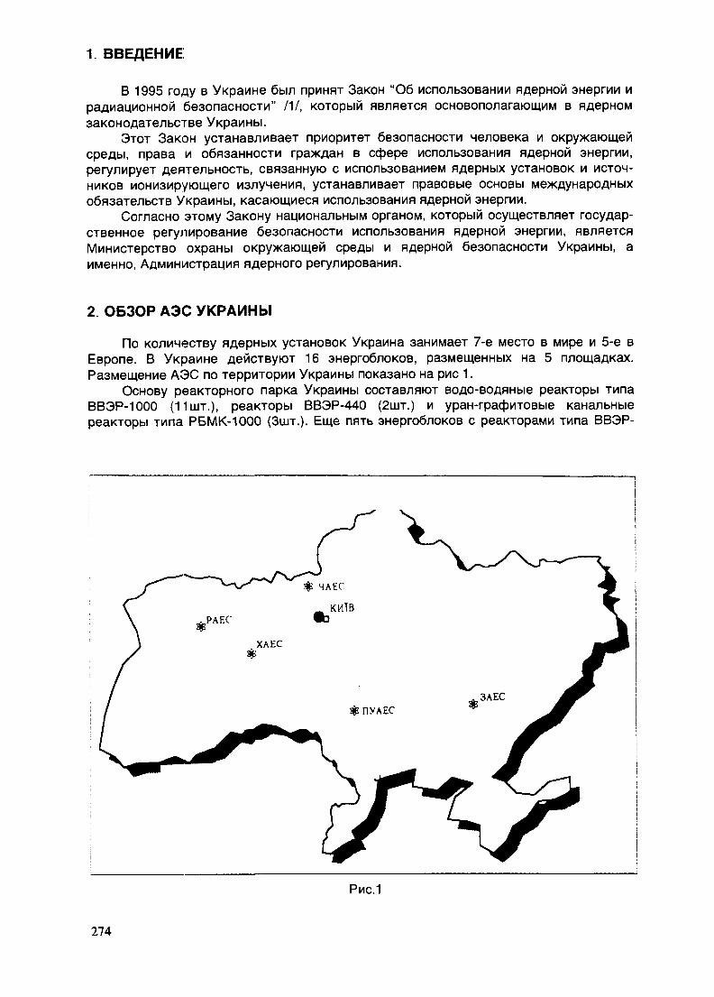
1. ВВЕДЕНИЕ
В 1995 году в Украине был принят Закон "Об использовании ядерной энергии ирадиационной безопасности" /1/, который является основополагающим в ядерномзаконодательстве Украины.
Этот Закон устанавливает приоритет безопасности человека и окружающейсреды, права и обязанности граждан в сфере использования ядерной энергии,регулирует деятельность, связанную с использованием ядерных установок и источ-ников ионизирующего излучения, устанавливает правовые основы международныхобязательств Украины, касающиеся использования ядерной энергии.
Согласно этому Закону национальным органом, который осуществляет государ-ственное регулирование безопасности использования ядерной энергии, являетсяМинистерство охраны окружающей среды и ядерной безопасности Украины, аименно, Администрация ядерного регулирования.
2. ОБЗОР АЭС УКРАИНЫ
По количеству ядерных установок Украина занимает 7-е место в мире и 5-е вЕвропе. В Украине действуют 16 энергоблоков, размещенных на 5 площадках.Размещение АЭС по территории Украины показано на рис 1.
Основу реакторного парка Украины составляют водо-водяные реакторы типаВВЭР-1000 (11шт.), реакторы ВВЭР-440 (2шт.) и уран-графитовые канальныереакторы типа РБМК-1000 (Зшт.). Еще пять энергоблоков с реакторами типа ВВЭР-
Рис.1
274

1000 находятся на стадии строительства на площадках ЮУ АЭС, Ровенской АЭС иХмельницкой АЭС на разной ступени строительной готовности. Запорожская станция,с введением в действие энергоблока №6 в 1995 году после снятия моратория, сталасамой мощной станцией Европы. Второй энергоблок ЧАЭС, начиная с 1996г., послепожара в турбинном отделении, законсервирован, блок №1 ЧАЭС окончательноостановлен в ноябре 1996года для проведения комплексных инженерных иссле-дований, как преддверия деятельности по проектированию снятия с эксплуатации.Информация про АЭС Украины приведена в таблице.
3. ДЕЯТЕЛЬНОСТЬ РЕГУЛИРУЮЩЕГО ОРГАНА УКРАИНЫ
Все действующие АЭС Украины были спроектированы по нормам безопасности70-х годов, действовавшим в бывшем СССР.
В начале своего становления регулирующий орган Украины в феврале 1992г.предложил администрациям АЭС осуществить комплексную переоценкубезопасности действующих блоков ( в том числе и пожарной безопасности).
Переоценка безопасности была необходима по следующим причинам:• в 1986г в государстве произошла крупнейшая в истории ядерная авария
(имеется в виду авария на ЧАЭС);• в бывшем СССР были введены новые нормативные документы по
безопасности;• необходимость оценки влияния эксплуатационной практики;• отсутствие в проектах АЭС таких важных разделов, как обеспечение
качества, метрологическое обеспечение, влияние внутренних и внешнихфакторов на безопасность АЭС, анализ запроектных аварий, а такжедостаточные проработки вопросов снятия АЭС с эксплуатации;
• необходимость применения современных методов анализа различныхдействительных режимов эксплуатации;
• необходимость использования вероятностных методов для обоснованияреализуемых на АЭС технических решений.
Переоценка безопасности действующих блоков АЭС Украины должна былапреследовать такие цели:
1. Получение объективной оценки уровня безопасности в соответствии с совре-менными национальными требованиями и рекомендациями международныхорганизаций.
2. Выработка обоснованного комплекса мероприятий с целью повышениябезопасности действующих блоков и реализация соответствующих решенийна строящихся блоках до ввода их в эксплуатацию.
Все действующие энергоблоки АЭС в соответствии с Законом Украины "Обиспользовании ядерной энергии и радиационной безопасности" до 2000 года должныполучить лицензии регулирующего органа на постоянную эксплуатацию. Учитывая,что в бывшем Советском Союзе не выполнялся полномасштабный анализбезопасности АЭС, необходимым условием получения лицензии на постояннуюэксплуатацию является представление в регулирующий орган отчетов по анализубезопасности.
Пожарная безопасность на АЭС Украины регулируется, как и во многих странах,двумя регулирующими органами:
В соответствии с Законом Украины "Про пожарную безопасность" 121 Мини-стерство внутренних дел Украины осуществляет регулирование и надзор заобеспече-нием пожарной безопасности на АЭС, как объекте общепромышленногоназначения. Целью регулирования и надзора при этом является обеспечениебезопасности чело-века при пожаре и сохранность материальных ценностей.
275
Министерство охраны окружающей среды и ядерной безопасности Украиныосуществляет регулирование и надзор за обеспечением пожарной безопасности наАЭС, как объекте атомной энергетики. Целью при этом является обеспечениеядерной и радиационной безопасности во время и после пожара на АЭС. Мырассматриваем те мероприятия по противопожарной защите АЭС, которые влияют наядерную и радиационную безопасность.
4. ОСНОВНЫЕ НАПРАВЛЕНИЯ РАБОТЫ РЕГУЛИРУЮЩЕГО ОРГАНАУКРАИНЫ
Работа регулирующего органа по обеспечению пожарной безопасности АЭСведется в таких направлениях:
• оценка проектов и анализ противопожарной защиты действующих энерго-блоков, проверка обеспечения выполнения критериев ядерной и радиацион-ной безопасности при пожаре на АЭС;
• анализ соответствия нормам и правилам по безопасности измененийпроектов АЭС, связанных с модернизацией и реконструкцией противопо-жарного оборудования действующих реакторных установок;
• надзор за деятельностью эксплуатирующих организаций;
• разработка нормативной базы по противопожарной защите АЭС, связаннойс обеспечением ядерной и радиационной безопасности.
Согласно современным требованиям нормативных документов, оценка проектови анализ достаточности мероприятий противопожарной защиты АЭС должныпроводиться на основе результатов выполнения анализа пожарного риска. Полныйколичественный анализ пожарного риска, соответствующий рекомендациям МАГАТЭ/3//4/, не выполнен до сих пор ни на одной станции Украины.
Правда, в этом году в рамках программы TACIS/PHARE на Ровенской АЭС(блоки №1, 2) с помощью ЭДФ проводились работы по анализу пожарной уязвимостипомещений дизель-генераторной станции с целью улучшения пожарной защиты этогоздания, на основании которого разработан перечень мероприятий.
Анализ пожаров, имевших место на блоке №2 Игналинской АЭС (1988г.) и наблоке №2 Чернобыльской АЭС (1991г.) и других АЭС, показал, что основнымипричинами пожаров было несоответствие пожарной безопасности кабельногохозяйства АЭС требованиям норм и правил по безопасности. Поэтому, учитывая то,что переоценка безопасности АЭС, подготовка отчета по анализу безопасности (спроведением и анализа пожарного риска) - это длительный процесс, регулирующийорган Украины предпринял срочные меры по повышению пожарной безопасностикабельного хозяйства АЭС Украины.
В 1994 году Коллегия Госатомнадзора Украины (так назывался тогда регули-рующий орган Украины) приняла Решение от 16.11.94г. №26 "О пожарной безопа-сности АЭС Украины"/5/, в котором обязала эксплуатирующие организации принятьконкретные меры по обеспечению пожарной безопасности кабельного хозяйстваАЭС. Во исполнение требований регулирующего органа орган государственногоуправления в сфере использования атомной энергии (так называемый Госкоматом)разработал "Комплексную целевую программу обеспечения пожарной безопасностикабельных сооружений АЭС Украины на 1995-1996 год"/6/.
Этой программой было предусмотрено выполнение следующих мероприятий:- разработка отраслевых нормативных документов по пожарной безопасности
ка-бельного хозяйства, в том числе и правил пожарной безопасности для АЭС;- проверка проектов, а также фактического состояния энергоблоков АЭС на со-
ответствие действующим нормам и правилам по безопасности, выявлениеотклонений от требований НТД;
276

- разработка условий безопасной эксплуатации кабельного хозяйства;- разработка и выполнение программы приведения кабельного хозяйства
энерго-блоков в соответствие с требованиями действующих норм и правил побезопасности.
Эти работы включали в себя:- проверку огнестойкости противопожарных барьеров, ограничивающих различ-
ные пожарные зоны, в которых размещаются разные каналы систем безопасности, спроведением огневых испытаний всех узлов и элементов кабельного хозяйства,вклю-чая противопожарные двери, проходки, огнезадерживающие клапаны икабели, покрытые огнезащитным покрытием;
- при необходимости покрытие кабелей огнезащитными материалами,разрешен-ными к применению регулирующими органами;
- выполнение анализа влияния огнезащитных покрытий на допустимые токовыенагрузки;
- определение термической и пожарной стойкости кабелей и разработка меро-приятий по предотвращению самопроизвольных включений механизмов в результатекоротких замыканий между жилами кабелей;
- для помещений, в которых отсутствует физическое разделение разныхканалов систем безопасности, проведение анализа обеспечения выполнениякритериев безо-пасности для ядерной установки (возможность безопасного остановареактора и его поддержание в подкритическом состоянии во время и после пожара,длительный отвод остаточных тепловыделений после останова реактора инепревышение допусти-мых проектом пределов выбросов радиоактивных веществ);
- реализация организационных мероприятий по обеспечению пожарной безопа-сности.
В дополнение к этой "Комплексной программе..." регулирующий орган выпустилинформационное письмо АЯР №9-96 /7/, где уточнил требования к проведениюанализа безопасности кабельного хозяйства.
Станции должны:• провести обследование кабельного хозяйства каждого энергоблока и
выявить отступления от действующих норм и правил;• проанализировать влияние выявленных отступлений от требований НТД на
функционирование систем безопасности и, следовательно, на безопасностьАЭС;
• разработать мероприятия по предупреждению отказов и/или уменьшениюпоследствий пожара (условия безопасной эксплуатации кабельногохозяйства);
• определить на случай возникновения пожара в конкретном помещении допу-стимость и продолжительность работы реакторной установки в основныхсостояниях и необходимость перевода ее в другое состояние;
• представить в регулирующий орган документы: "Условия выполнения выше-перечисленных критериев безопасности" и "Программу приведения кабель-ного хозяйства АЭС в соответствие требованиям действующих НТД.
Выполнение этих требований введено в особые условия лицензии на эксплу-атацию энергоблоков.
Выполнение требований регулирующего органа является первым этапом работпо выполнению анализа опасности возникновения пожара на АЭС.
Конечно, мы понимаем, что такой анализ без проведения полноценного коли-чественного анализа несовершенен и носит качественный характер, но на сегод-няшний день даже такой анализ принесет несомненную пользу для обеспечениябезопасности АЭС.
Работа по выполнению полного количественного анализа опасностивозникновения пожара с применением рекомендаций международных организацийтакже намечается в перспективе.
277
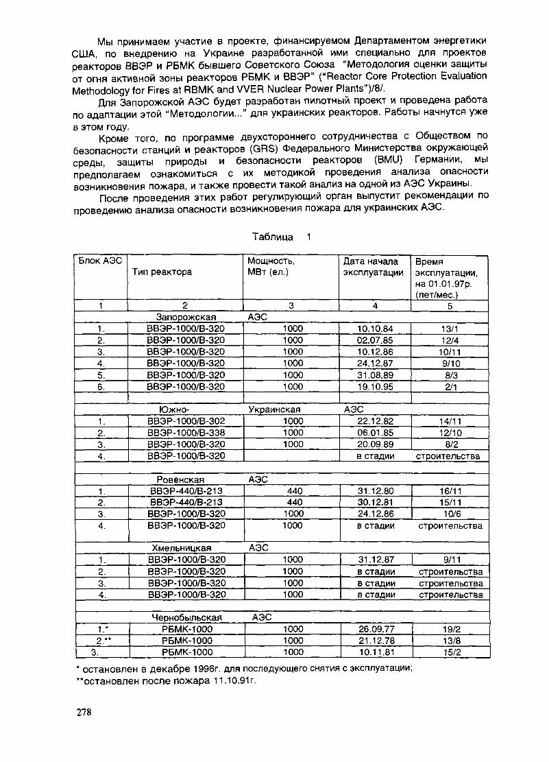
Мы принимаем участие в проекте, финансируемом Департаментом энергетикиСША, по внедрению на Украине разработанной ими специально для проектовреакторов ВВЭР и РБМК бывшего Советского Союза "Методология оценки защитыот огня активной зоны реакторов РБМК и ВВЭР" ("Reactor Core Protection EvaluationMethodology for Fires at RBMK and VVER Nuclear Power Plants")/8/.
Для Запорожской АЭС будет разработан пилотный проект и проведена работапо адаптации этой "Методологии..." для украинских реакторов. Работы начнутся уже
в этом году.Кроме того, по программе двухстороннего сотрудничества с Обществом по
безопасности станций и реакторов (GRS) Федерального Министерства окружающейсреды, защиты природы и безопасности реакторов (BMU) Германии, мыпредполагаем ознакомиться с их методикой проведения анализа опасностивозникновения пожара, и также провести такой анализ на одной из АЭС Украины.
После проведения этих работ регулирующий орган выпустит рекомендации попроведению анализа опасности возникновения пожара для украинских АЭС.
Таблица 1
Блок АЭС
1
1.2.3.4.5.6.
1.2.3.4.
Тип реактора
2Запорожская
ВВЭР-ЮОО/В-320ВВЭР-ЮОО/В-320ВВЭР-ЮОО/В-320ВВЭР-ЮОО/В-320ВВЭР-ЮОО/В-320ВВЭР-ЮОО/В-320
Южно-ВВЭР-ЮОО/В-302ВВЭР-ЮОО/В-338ВВЭР-ЮОО/В-320ВВЭР-ЮОО/В-320
Мощность,МВт (ел.)
3АЭС
100010001000100010001000
Украинская100010001000
Дата началаэксплуатации
4
10.10.8402.07.8510.12.8624.12.8731.08.8919.10.95
АЭС22.12.8206.01.85
^_ 20.09.89в стадии
Времяэксплуатации,на 01.01.97р.(лет/мес.)
5
13/112/4
10/119/108/32/1
14/1112/10
8/2строительства
1.2.3.4.
1.2.3.4.
РовенскаяВВЭР-440/В-213ВВЭР-440/В-213
ВВЭР-ЮОО/В-320ВВЭР-ЮОО/В-320
ХмельницкаяВВЭР-ЮОО/В-320ВВЭР-ЮОО/В-320ВВЭР-ЮОО/В-320ВВЭР-ЮОО/В-320
АЭС440440
10001000
АЭС1000100010001000
31.12.8030.12.8124.12.86в стадии
31.12.87в стадиив стадиив стадии
16/1115/11
10/6строительства
9/11строительствастроительствастроительства
1.*2 . "
3.
ЧернобыльскаяРБМК-1000РБМК-1000РБМК-1000
АЭС100010001000
26.09.7721.12.7810.11.81
19/213/815/2
* остановлен в декабре 1996г. для последующего снятия с эксплуатации;"остановлен после пожара 11.10.91г.
278
• Следующее направление деятельности регулирующего органа - анализсоответствия противопожарной защиты изменений проектов АЭС,связанных с модернизацией и реконструкцией действующих реакторныхустановок, нормам и правилам по безопасности;
Для повышения безопасности (в том числе и пожарной безопасности)действующих энергоблоков разработаны и выполняются различные программымодернизации АЭС /9/-/11/.
Учитывая то, что глубокий анализ опасности возникновения пожара на блокахАЭС не проводился, и обосновать безопасность энергоблока при наличии отклоненийот действующей НТД эксплуатирующая организация не может, поэтому программыповышения пожарной безопасности АЭС построены, как правило, на ликвидацииотступлений от требований действующей НТД. При этом, учитывается опыт эксплуа-тации аналогичных проектов АЭС и рекомендации международных организаций.
Программы модернизации включают такие вопросы пожарной защиты и защитыот взрывов:
- замена противопожарных дверей на двери с огнестойкостью 1,5 часа в поме-щениях, содержащих системы, важные для безопасности;
- покрытие кабелей и других элементов огнезащитными материалами;- замена пластикатного покрытия полов на огнестойкие;- введение противопожарных барьеров между разными каналами систем
безопа-сности;- повышение огнестойкости металлоконструкций каркаса машзала;- установка огнезадерживающих клапанов в воздуховодах систем вентиляции;- внедрение систем газового пожаротушения для тушения помещений, содержа-
щих электрическое и электронное оборудование систем контроля и управления;- модернизация систем пожарной сигнализации ( имеющаяся система пожарной
сигнализации не аттестована на применение в условиях АЭС, сейсмичность ирадиационная стойкость не отвечает необходимым требованиям);
- повышение надежности водоснабжения систем водяного пожаротушения;- разделение больших пожарных отсеков на меньшие;- повышение термической и пожарной устойчивости электрических присоеди-
нений;- обеспечение контроля концентрации водорода в гермооболочке;- внедрение схемы автоматического по сигналу "Пожар" сброса водорода из
кор-пуса генератора за пределы машзала;- замена горючих смазочных масел в системе смазки главных циркуляционных
насосов на негорючие;и т.д.
К сожалению, необходимо отметить, что часто выполнение этих мероприятийсрывается из-за недостатка финансирования.
Другим направлением деятельности регулирующего органа являетсяразработка нормативной базы по обеспечению пожарной безопасности энергоблоковАЭС, связанной с обеспечением ядерной и радиационной безопасности.
Подготовлены такие документы:• "Требования к противопожарной защите энергоблоков АЭС, связанные с
обеспечением ядерной и радиационной безопасности" /12/. Первая редакцияэтого нормативного документа уже разработана и находится на обсуждении.Готовится 2-ая редакция документа. В этом нормативном документеизложены основные критерии и принципы обеспечения ядерной ирадиационной безопасности во время и после пожара на АЭС.
• "Процедура инспекции по проверке безопасного останова реактора припожаре на энергоблоках АЭС'713/. Находится на рассмотрении.
Кроме этого, ведется разработка отраслевой нормативной базы с нашимсогласованием:
279
• проведен пересмотр нормативного документа бывшего Советского Союза ВСН01-87 "Противопожарные нормы проектирования атомных станций с водоох-лаждаемыми реакторами на тепловых нейтронах" /14/, первая редакциядокумента находится на стадии согласования;
• выпущена первая редакция отраслевого документа "Правила пожарной безопа-сности АЭС" /15/, находится на согласовании;
• разрабатываются отраслевые общие технические требования для ОЗС,применяемых на АЭС /16/;
• выпущен отраслевой документ "Расчетная методика "Определениекоэффициентов снижения длительно допустимых токовых нагрузок силовыхкабелей при покрытии их ОЗС и проходе через огнестойкие заделки иогнепреградительные пояса'717/.
Надзор за деятельностью АЭС
На всех этапах жизненного цикла АЭС инспекциями регулирующих органовосуществляется надзор за деятельностью АЭС. При этом:
- проводится надзор за соответствием состояния АЭС и режимов эксплуатациитребованиям нормативно-технической документации и условиям выданной лицензии,
- проверяется соответствие пожарной безопасности АЭС нормам и правилам побезопасности,
- проверяется возможность сохранения безопасности АЭС, защиты персоналапри пожаре и после пожара,
- при наличии отклонений от требований НТД проверяется наличие компенси-рующих мероприятий и оценивается достаточность их для обеспечения безопасностиАЭС.
ВЫВОДЫ:
1. Установлены различные недостатки в обеспечении пожарной безопасности АЭСсамими эксплуатирующими организациями, в том числе и с помощью международныхэкспертов. Проводятся определенные мероприятия с целью повышения пожарнойбезопасности АЭС.На сегодняшний день основные проблемы для Украины:-финансирование проектов модернизации старых и строящихся энергоблоков АЭС;-необходима помощь при проведении анализа опасности возникновения пожарадействующих энергоблоков.
2. Регулирующий орган Украины прикладывает определенные усилия в обеспечениипожарной безопасности на АЭС Украины, доведении пожарной безопасностидействующих энергоблоков до уровня современных норм и правил по безопасности.
ЛИТЕРАТУРА
/1/ Закон Украины "Об использовании ядерной энергии и радиационнойбезопасности", 1995
121 Закон Украины "О пожарной безопасности", 1995/3/ "Fire Safety in Nuclear Power Plants"; IAEA Safet Guide, IAEA Safety Series
NO.50-SG-D2, Вена, 1992/4/ "Fire hazard analysis for WWER nuclear power plants", IAEA-TECDOC-778,
Vienna; 1994
280
/5/ Решение Коллегии Госатомнадзора Украины от 16.11.94г. №26 "О пожарнойбезопасности АЭС Украины", 1994
/6/ "Комплексная целевая программа повышения пожарной безопасностикабельного хозяйства на АЭС Украины", 1995
/7/ Информационное письмо Администрации ядерного регулирования Украины№9-96, 1996
/8/ "Методология оценки защиты от огня активной зоны реакторов РБМК и ВВЭР", DOE/NE-0113; декабрь 1996, Департамент энергетики США
/9/ "Программа повышения безопасности АЭС с реакторными установкамиВВЭР-1000,440", 1994
/10/ "Программа повышения безопасности энергоблоков Чернобыльской АЭС",1994
/11/ Программа модернизации энергоблоков АЭС Украины с реакторами ВВЭР-1000(В-320), 1996
/12/ "Требования к противопожарной защите энергоблоков АЭС, связанные собеспечением ядерной и радиационной безопасности", проект 1997
/13/ "Процедура инспекции по проверке безопасного останова реактора припожаре на энергоблоках АЭС", проект, 1997
/14/ "Противопожарные нормы проектирования атомных станций сводоохлаждаемыми реакторами на тепловых нейтронах" (ВСН01-87), 1987
/15/ "Правила пожарной безопасности АЭС", проект, 1997/16/ Отраслевые общие технические требования для огнезащитных материалов,
применяемых на АЭС, проект, 1997/17/ Отраслевой документ "Расчетная методика "Определение коэффициентов
снижения длительно допустимых токовых нагрузок силовых кабелей припокрытии их ОЗС и проходе через огнестойкие заделки иогнепреградительные пояса", 1995
I NEXT 9I ten-:.-
281
IAEA-SM-345/12
GENERAL FIRE PROTECTION GUIDELINES FOREGYPTIAN NUCLEAR INSTALLATIONS
XA9847526S.M. RASHAD, A.Z. HUSSEIN, F.H. HAMMADNational Center for Nuclear Safety and Radiation Control,Atomic Energy Authority,Cairo, Egypt
Abstract
The purpose of this paper is to establish the regulatory requirements that will provide and ensurefire protection of Egyptian nuclear installations. Two or more classes of occupancy are considered tooccur in the same building or structure. Fire protection measures and systems were reviewed for four ofthe Egyptian nuclear installations. These are Egypt's first research reactor (ET-RR-1) building andsystems, hot laboratories buildings and facilities, the building including the AECL type JS-65OO industrialcobalt-60 gamma irradiator "Egypt's Mega Gamma I" and Egypt's second research multi-purpose reactor(MPR). A brief review is given about fire incidents in Egypt, and descriptions of the only fire reportedat one of the Egyptian nuclear installations over more than 35 years of operating these installations. Thestudy outlines the various aspects of fire protection with a view to define the relevant highlights andscope of an Egyptian guidelines.
1. FIRE EVENTS IN EGYPT
Fire risk assessment studies indicate that the contribution of fires to severe accidents atlarge facilities is significant and that fire may contribute in excess of 50% of the total frequencyof accidents leading to large scale losses. In addition to the public health risk represented byfires, the financial risk due to direct fire damage, as well as loss of revenues as a result of fire canbe significant. In the last few years there were numerous fires that occurred in a number ofindustrial and petroleum facilities in Egypt and the evaluation of losses in many of them exceededseveral millions Egyptian pounds (L.E.).
Some recent studies in the area of fire protection have been made in Egypt [1,2]. Itbecame clear during data collection that there is a lack of statistics on fire incidents, research andsuitably applicable codes.
The study and analysis of fire events in Egypt [1] had throw light upon the importanceof assessing fire hazards and helped deeply the understanding of fire protection concepts andrequirements.
1.1. Population, and Population Activities
One of the objectives of the study of fire events in Egypt was to investigate any relationthat might exist between the frequency of fire incidents and the population of the district, thedensity of population, the activities of the inhabitants (industrial, agricultural and/or commercial)and other features.
Egypt's population nearly doubled from 9.7 million to over 19 million persons in the 50years from 1897 to 1947. The next doubling took less than 30 years (from 1947 to 1976). In1996, the Egyptian population was 61 million. The population growth rate, which was 1.5percent annually at the beginning of this century, fell for a period and then began rising rapidlyfrom the early 1950s, reaching a rate of approximately 2.5 percent in the early 1960s. For theperiod 1960-1967, the growth rate slackened, but by early 1980s it had risen again to nearly 3percent [1].
283
The problems and risks associated with the rapid rate of population growth arecomplicated further by one basic fact about Egypt, namely the extreme scarcity of cultivable landrelative to people. Over 97 percent of Egypt's 1996 population of 61 million is crowded on toless than four percent of the total area of one million square kilometers. The remaining 96percent of the land area is desert.
The concentration of the population in the Nile Valley and the Delta, gives Egypt in 1996,density rates of 61 persons per square kilometer for the total area but over 1520 persons persquare kilometers of inhabitable land. In Cairo, density reaches 28332 persons per squarekilometer, now about 42% of the total urban population lives in Cairo and Alexandria.
Egypt has made great progress in the field of traditional industries, namely, spinning andweaving industries. Significant progress has also been made in modern industries, such asmetallurgical and chemical and other engineering industries. The state contributed to a mostefficient drive towards increasing production in many industries, such as iron and steel, ceramicsand porcelain, cement, paper and fertilizer and the petroleum industry. Im Egypt about 33% ofthe population works in agriculture and 22% in the different industries.
1.2. Review and Analysis of Fire Events
Review and analysis of fire incidents in Egypt during twelve years, from Jan. 1980 toDec. 1991 was performed [1]. This study is considered as the first comprehensive analysis of fireincidents in Egypt, the data required to analyze the fire incidents in Egypt was obtained from theyearly reports issued by the civil defense and general security organizations of the Ministry ofInterior. During the phase of data collection it is obvious that there are incomplete records aboutfires and the way of reporting them. It is clear that fire protection, fire fighting, fire reportingsystems and fire codes need to be reviewed.
The analyses include the distribution of fire events and their losses over the differentgovernorates and over the months of the year, the primary causes, the classification of eventsaccording to the place of occurrence. Also the study throws some light on arson fire events. Thestudy provides general picture of fire experience over time, for a greater insight more elementshave be provided by the Ministry of Interior to describe fire incidents.
A summary of fire statistics for the total incidents reported in Egypt (1980 - 1991) isgiven in Table I. The recorded number of civilian deaths, civilian injuries and monetary losses,are given. The average annual number of fires was 21 thousands events (TFI) in the Republicresulted in 227 deaths and 752 civilian injuries in the average. The average annual value of themonetary losses due to fires was about eleven million L.E.
From the study the following rated were calculated: One injury for each 27 TFI and onedeath for each 92 TFI during the study period. The average values were: one TFI for every 2677Egyptian person in the year and one TFI occurred in the year for each 48.2 km2 of the republicarea compared to 1.93 TFI/km2 of the inhabitable land.
The disiribution of incidents over the different governorates is more or less similar in allyears of investigations where Cairo, Alexandria, Dakahliya and Giza governorates have the largenumbers of fire incidents. These governorates are the ones with larger population and populationintensity and they are industrial areas (more than 70% of the total industries are in Cairo andAlexandria).
Among all industrial facilities incidents those that had been occurred at petroluemcompanies were the most severe from the point of view of monetary losses. The incidents thathad been occurred at village houses are the most severe regarding the No. of civilian deaths andinjuries recorded in one incident (more than 110 injuries and 60 deaths in an incident).
284

TABLE I. TOTAL FIRE STATISTICS
Year
198019811982198319841985198619871988198919901991
TotalFires157131718517660194762086821687227732417722776233512241721163
CivilianInjuries9806639407611029753657808806781808701
CivilianDeaths291179165310269184303190198246182200
MonetaryLosses (10s L.E.)
3586122392331089007200170438090669994659139169107045
About 110 arson fire felonies, on the average, was reported annually in Egypt, 50% ofthem occurred in Cairo, Alexandria and Menofia governorates (40% of the TFI were recorded inthese three governorates) with 25% of them occurred in Cairo governorate.
The distribution of arson fires, according to places of their occurrence was as follows: Theaccidents occurred at shops, residences, coffee shops, farms, factories, schools, streets, mosquesand other places From the study it has been found that about 50% of the arson fires occurredinside residential buildings followed by commercial shops and farms and annually about 4 arsonfelonies were recorded at schools and one or two at mosques.
Based on the results of the study and investigations done codes and standards need to bereviewed and applied. Also a comprehensive national fire incident reporting system have to beestablished to collect, analyze and disseminate information on fire events in order to be able toreduce their consequences. The main recommendations of the study include as the Ministry ofInterior is the only organization in Egypt with overall responsibility for fire protection and firefighting measures, it is recommended to have:
- Center for fire research whose scope extends from exploratory research on combustion to thedevelopment of computer programs to solve practical fire protection engineering problems.
- A bachelor degree in fire protection engineering has to be offered by one of the departmentsof a faculty of engineering.
- Fire protection basics have to be included as one of the educational subjects in preparatory andsecondary schools, to raise the level of safety culture regarding fire protection issues.
2. EGYPTIAN NUCLEAR INSTALLATIONS
The Egyptian Atomic Energy Authority (AEA) has 4 research centers, the activities ofthe AEA run into four major fields: research and technological projects, radiation protection andsafety, society services activities, regional and international cooperation. The AEA houses somemajor and research facilities, among them, Egypt's first Research Reactor ET-RR-1, the Hotlaboratories Center at Inches, and the Industrial Irradiator Facility (Egypt's Mega Gamma-1) atNasr City.
285
The major near commissioning projects are Egypt's Second Research (Multi - Purpose)Reactor (MPR) and the Cyclotron Accelerator.
The MPR is an advanced swimming pool research reactor contracted with INVAPArgentina in Sept. 1991. This is 22 MWT reactor will be used in radiostope production, materialstesting research, reactor physics research and reactor thermal engineering research.
The Cyclotron complex is based on a compact AVF cyclotron of Russian type MGC-20with K = 20. The accelerator is intended to be used in a multidsciplinary way. The complexcontains provisions for radioisotope production, fast neutron research applications, use ofcyclotron beams in nuclear analytical techniques, biomedical and nuclear medicine applications,and surface modifications and treatment. Shielding design of walls, floors and ceilings are donein accordance with ICRP-60 recommendations with dose limit rates to non-occupational exposedindividuals not exceeding 0.5 mSv/y.
Both the reactor and the cyclotron are to be commissioned by the end of 1997. The fireprotection system design for Egypt's second research reactor MPR was reviewed by the staff ofthe Egyptian regulatory body. A brief description of the system is given below.
The fire alert system is responsible for detecting and providing early fire alarm inside thereactor building. The system is controlled by a fire alert station located in the security guardsoffice, where security personnel are presented at all times. An alarm panelboard is installed inthe Control Room. The reactor building has been divided into 13 fire sectors or zones. Thisdivision has been performed according to the building's physical characteristics and itsoperational areas,. Also, Each floor is divided into two fire sectors, one to cover the cold zone andthe other to cover the hot or controlled zone.
Fire alarm center operates with conventional type fire alarms, extinction system automatictripping happens when activation of two detectors, from the circuit of room to be protected isdetected. In control room and in auxiliary control room fire alarm repetition panels are installed.Electronic thermal detectors, ionic smoke detectors, and photoelectric smoke detectors are usedand distributed along the different fire sectors considering the fire risk of each area.
The fire extinguishing system consists of the following elements: fire protection waternetwork which will include a perimetral external ring and a line of internal hydrants, one perfloor, located in the building's cold zones, automatic extinction installation by, means of agaseous agent in certain rooms (control room, auxiliary control room, emergency control room,electrical board) and set of manual extinguishers of various types and capacities appropriatelydistributed among cold and hot zone rooms and premises.
3. FIRE AT THE INDUSTRIAL COBALT-60 GAMMA IRRADIATOR "EGYPT'SMEGA GAMMA I "
The Egyptian Atomic Energy Authority possesses and operates AECL type JS-6500industrial Cobalt-60 gamma irradiator "Egypt's Mega Gamma I". The facility has been inoperation at the National Centure for Radiation Research and Technology (NCRRT) sinceJanuary 1979 at an initial Cobalt-60 capacity of 400 kCi.
The plant is furnished with a ventilated concrete biological shield, a water pool for sourcestorage, a principal mechanical conveyor, an extra research channel for pilot irradiation of highdensity products, a source passes mechanism with peneumatic pushers and all other devices forinterlocks, radiation safety and absorbed dose measurements.
On September 5, 1995 a fire started inside the irradiation rom. The alarm system wasactuated at 8:23 in the morning, anti-fire measures were taken and the fire was totallyextinguished at 11 : 30. The fire was initially detected automatically by overhead's signal fromthe control panel. The source was automatically lowered to its safe position in the pool.
286
At the time of fire occurrence, the plant was in operation since four days. The plant wasoperated using the research channel. The main conveyor was not used and it was loaded by 60dummy carboard boxes eatch of 30 kg. The research channel was loaded by eye ointmentaluminum tubes of tetra cyclone packed in small (10x10x10 cm) carboard boxes. The ointmentwas irradiated in an experiment for Pfizer Drug Company for a dose of 2 MRad.
More than 2 tons of dummy boxes were destroyed. There was not any releases ofradioactivity as a result of the fire. Also no one was injured due to fire or by any other cause.Outside fire brigade arrived in few minutes after their call (after about 10 minutes from thedetection of the fire). They started to extinguish the fire after being sure that there was not anyradiation releases. Water alone was first used for about 90 minutes and then they used water-chemical foam to fill up the whole irradiation room.
The cause of fire was investigated by a group of specialists from the Criminal Lab andexperts of NCRRT. They came to a conclusion that the fire started at the bacalite base of neonfluorescent bulb as a result of bad contact. After fire occurrence all the systems of the facility hadbeen reviewed and lighting and fire protection systems are updated. This fire is the only reportedfire at any one of the Egyptian nuclear installations over about 35 years of operation.
4. SPECIAL PROBLEMS IN FIRE PROTECTION AT NUCLEARINSTALLATIONS
The special problems encountered in nuclear installations are due to the presence ofdifferent radioactive substances (solid, liquid or gaseous) with varying activity and decay rates.These radioactive substances are the cause for the division of the installation premises into whatare sometimes called controlled and uncontrolled areas in order to limit the exposure of theemployees when working in different parts of the installation. The division of the premises intocontrolled and supervised areas affects the arrangement of the fire protection systems and thedesign of ventilation systems.
The presence of gaseous or airborne radioactive substances requires pressure differentialsto maintain the flow of air from the less towards the more contaminated rooms and regions.Smoke extraction methods must accommodate this principle.
Manual fire fighting in a nuclear installation may prove to be difficult and timeconsuming operation, since the fire fighters must be given sufficient protection against radiationexposure, be it by limiting the exposure time or by wearing special protective equipment. Theradiation dose limits to which fire fighters and other emergency personnel may expose themselvesis a subject on which no simple statement can be made. One kind of exposure comes fromexternal exposure to ionizing radiation. Another comes from radioactive substances which maybe inhaled or ingested. The exact limits should be defined by the emergency program establishedfor the particular installation.
5. FIRE PROTECTION GUIDELINES
The National Center for Nuclear Safety and Radiation Control (NCNSRC) is the nationalauthority responsible for the surveillance of the safety of nuclear facilities. The regulatoryactivities encompass also the fire protection of the facilities in so far as they affect the nuclearsafety of the facilities. In its regulatory work, NCNSRC takes into account the activities of otherauthorities and organizations.
General fire protection guidelines which have to be enforced are described in this paperafter reviewing the conditions at Egypt's nuclear installations and after going through theavailable guides and standards [3-9].
287

The requirements given in this paper are not applied at the exisiting Egyptian nuclearfacilities. The fire protection modifications that may be needed for them are considered case bycase.
5.1. Design Requirements
Protection from fire and fire related explosions assumes importance in the overall designof a nuclear facility in so far as it forms a crucial part of the safety considerations. Thereforeplanning for fire protection shall be an integral part of the design stage and not an afterthought.Fire protection shall continue to be a well planned and implemented program throughout the lifeof the facility.
5.1.1. Structural fire protection
Structural fire protection measures shall be capable of, as far as possible, ensuring alonethe safety of a nuclear facility in the event of fire. Therefore, the functional design and layoutconsiderations of a nuclear facility and its buildings form the prerequisites for adequate fireprevention and protection. One design aspect shall be the housing of the proportions of thefacility most important to nuclear safety in separate buildings apart from the conventional partsof the facility, there by facilitating protection against fire of the items important to nuclear safety.The buildings containing items important to nuclear safety should be fire resistant.
The electrical power supplies between the facility and the national grid shall be arrangedin such a way that the probability of losing all supplies simultaneously due to a fire is minimized.
The process electrical and instrumentation systems at the facility shall be diversified andpartitioned into different fire areas in such a way that in case one fire area is destroyed, there arestill sufficient number of systems available to ensure the safety of the facility. The boundarybetween the controlled and uncontrolled zones shall also be the boundary between fire areas.
The requirements set forth in the safeguards shall also be taken into account in the designand dimensioning of the fire areas, access and escape routes and fire doors.
The fire areas should have a minimum fire resistance of two hours. The access and escaperoutes needed for the safe shutdown of the facility, the access routes for fire brigades, at least oneemergency exit in each building, shall be so designed and constructed that these areas can be usedsafely at least far two hours under postulated fire conditions [4].
The fire resistance of the separating elements of fire boundaries such as doors andhatches, cable and pipe penetrations shall be equal to that required for the walls, the floors, andthe ceiling structures.
Ventilation should not degrade fire protection of the facility; fire areas containingredundant systems important to nuclear safety should not be provided with mutual ventilationsystems that could increase fire hazards. In the design of the ventilation systems, it shall be takeninto consideration that in the event of a fire they can quick switched off quickly and reliably.
5.1.2. Active fire protection
The objective of active fire protection measures is an early detection and effectivelyextinguishing a fire. Acive fire protection comprises a fire detection and alarm system, and fireextinguishing systems and other fire suppression arrangements as complementary measures tostructural fire protection. However, the safety of the facility shall not, in any parts, be dependenton the active fire protection measures alone.
288

To facilitate fast suppression of fire and to minimize damage and hazards, effective fireextinguishing systems should be designed for the facility. Fixed reliable fire extinguishingsystems shall be designed for the facility. They should be provided for the following rooms andsystems, irrespective of the lay-out design of the facility:
(1) Cable spaces containing redundant cables which are important to safety not housed inseparate fire areas.
(2) Large oil systems for the main circulation pumps.(3) Diesel generators (if existed)(4) Spaces and systems for which considerable amounts of radioactive substances can be
released into rooms or into the environment by a fire.
Removal of extinguishing water shall be arranged from rooms equipped with fixed waterextinguishing systems. The buildings of the factility should be provided with adequate accessand escape routes. These routes shall be spacious and easy to pass through.
The facility shall be equipped with an emergency lighting with the purpose of ensuring safetyof passage inside the building when the normal lighting is out of order. Emergency lightingmeans both signal lights and standby lighting. The purpose of standby lighting is to remain onor to be switched on automatically or manually when the normal lighting goes out. Emergencylighting shall also be located near the signs indicating the escape routes and emergency exists.
5.2. Construction Permit
Before the construction permit, the preliminary Safety Analysis Report (PSAR), and thecomplementary topical reports must be submitted to the regulatory body. These documents shallprovide a description of how the fire protection requirements are met in the design of the facility.The division of items should be as follows [3]:
(1) Description of regulations, guides and standards used in the design.(2) Description of fire loads.(3) Description of fire areas.(4) Description of ventilation in the event of a fire.(5) Preliminary description of the fire detection and alarm system, and fire extinguishingsystems.(6) Description of the escape routes and emergency exists.(7) Description of the fire hazards analyses.
5.3. Fire Hazard Analysis
The purposes of the fire hazard analysis are:(l) To identify items important to safety
(2) To analyze the anticipated fire growth and the consequences of the fire with respect to itemsimportant to safety.
(3) To determine the required fire resistance of fire barriers.(4) To determine the type of fire detection and protection means to be provided.(5) To identify cases where additional fire separation or fire protection is required, especially for
common mode failures, in order to ensure that items important to safety will remainfunctional during and following a credible fire.
(6) To verify that the safety systems required to shut the facility down, remove residual heat (ifrequired), and contain radioactive material are protected. They should be protected againstthe consequences of fires so that they are still capable of performing their safety functions.
289
To secure effective nuclear safety for the installation, the fire hazard analysis must cover allareas of the site, including the non-nuclear facilities. Assessment of all the site areas is necessaryto ensure that all the fire hazards which potentially threaten nuclear safety have been addressed.Fire protection measures (both passive and active) should also be considered for any areacontaining concentrations of combustibles, even though the area may not contain or exposenuclear safety system. This additional protection may be provided in order to minimize bothproperty damage and installation down that could occur as a result of fire.
For identification of fire hazards and safety systems, the information that must be obtainedcan be separated into seven categories: fire compartment inventory, combustibles inventory,ignition sources, passive fire protection measures, active fire protection systems, items outsidethe fire compartment, and field verification.
5.4. Supervision of Construction
After the issuance of the construction permit, the regulatory body supervises the constructionof the facility. In order to get a sufficiently detailed picture of he implementation of the fireprotection arrangements at the nuclear facility, the applicant shall furnish the regulatory bodywith accounts of the following items:
(1) Wall, floor and ceiling structures of the fire boundaries.(2) Fire doors and hatches and their fire resistance.(3) Types and fire resistance of fire stops used in cable and pipe penetrations.(4) Fire detection and alarm system.(5) Fire extinguishing systems.(6) Fire venting and smoke extraction.(7) Removal of extinguishing water.(8) Emergency lighting.
The results of the fire hazards analyses shall be reported comprehensively to facilitate theassessment of the fire resistance of the structures.
5.5. Operating Permit
For this stage, the Final Safety Analysis Report has to be submitted to the regulatory body.In addition, accounts of items relating to the planned fire protection arrangements shall also besubmitted.
All the organizations which might be called to a fire, should be consulted at the planningstage to avoid the need for later adoption of protective measures at increased cost and delay.
A fire prevention and protection organization should be established as an integrateddepartment of plant management and provided sufficient responsibility, authority and manpowerto permit effective performance on a 24 hour day basis.The areas of consideration of facility management in designing their preplanning for anemergency program should include as a minimum the following requirements.
(1) A self inspection program.(2) An emergency and fire fighting organization with an outline its training program.(3) Personnel control as it relates to emergency situations.(4) Health Physics group responsibilities.
290
(5) A coordinated response plan with public emergency forces (Civil Defense .., Ministry ofHealth ) including periodic drills.
(6) Procedures for loss minimization and decontamination.(7) The safeguarding of valuable process data and records.(8) Community relations.
The self inspection program should be formal and conducted objectively by knowledgeableemployees who have a good understanding of the hazards to be safeguarded. The reports of theseinspections should be reviewed by management at a level which can initiate corrective action.The self inspection report forms should be specifically designed for each facility and include allaspects of basic fire protection as well as those unique to the facility.
Fire emergency procedures shall be established for all personnel. Sufficient training shall beconducted to ensure that every person is familiar with the emergency procedures and his assignedresponsibilities.
Drills shall be held at least quarterly, but should be held more frequently as operations permit,especially in the case of buildings involving high fire risk.
5.6. Fire Program
The fire protection manager is responsible for the implementation of the fire program. Thisprogram usually encompasses both prevention and protection and should include the following:
(1) Interpretation of applicable codes, regulations and standards.(2) Design review of the initial fire protection system, alterations and extensions.(3) Review of and consultation on fire safety aspects of process changes.(4) Issue of hot work permits (welding, cutting,.. etc.).(5) Inspection of equipment for fire hazard.(6) Relationships with insurers (where applicable).(7) Liaison with official safety organizations.(8) Fire protection equipment inspection and maintenance.(9) Fire brigade organization and training.(10) Emergency fire procedures.(11) Fire and damage investigations and reports.(12) Supervision during impairment of protection (and notification to insurers if applied).(13) Emergency planning for minimization of effects of damage.
5.7. Supervision During Operation
The regulatory body supervises the inservice inspections performed by the owner of thefacility to the extent deemed necessary and carries out inspections relating to fire protection inaccordance with its own program.
REFERENCES
[1] Rashad, S.M., Review and Analysis of Fire Events in Egypt, 1980-1991, Statistical Journalof the Institute of Statistical Studies and Research, Cairo University, Cairo (1995).[2] Rashad, S.M., Hussein, A.Z., Hammad, F.H., Comparative Study of Fire ProtectionGuidelines in Nuclear Power Plants, Proceedings of the International Symposium of FireProtection and Fire Fighting in Nuclear Installations, IAEA, Vienna (1989).
291

[3] STUK GUIDE YVL 4.3, Fire Protection at Nuclear Facilities, 1987.[4] INTERNAT1 ON AL ATOMIC ENERGY AGENCY, Fire protection in Nuclear Power Plants,A Safety Guide, IAEA Safety Series No. 50-SG-D2, IAEA, Vienna (1979).[5] NATIONAL, FIRE PROTECTION ASSOCIATION, Recommended Fire Protection PracticeFor Nuclear Research Reactors, Rep. NFPA- 802, NFPA, Boston, MA (1983).[6] NATIONSL FIRE PROTECTION ASSOCIATION, Recommended Fire Protection PracticeFor Facilities Handling Radioactive Materials, Rep. NFPA-801, NFPA, Boston, MA (1983).[7] UNITED STATES NUCLEAR REGULATORY COMMISSION, Fire Protection For NPPs,Regulatory Guide RG1.12, NRC, Washington, DC (1977).[8] INTERNATIONAL ATOMIC ENERGY AGENCY, Evaluation of Fire Hazard Analysis ForNuclear Power Plants, IAEA Safety Series No. 50-P-9, IAEA, Vienna, (1995).[9] INTERNATIONAL ATOMIC ENERGY AGENCY, Inspection of Fire Protection Measuresand Fire Fighting Capability At NPPs, Safety Series No. 50-P-6, IAEA, Vienna (1994).
292
UPGRADING PROGRAMMES
(Session 6)
Chairperson
V.I. POGORELOVRussian Federation

IAEA-SM-345/14
U P G R A D I N G O F F I R E P R O T E C T I O N A R R A N G E M E N T SA T M A G N O X P O W E R S T A T I O N S Illlllllllllllllllllllllllllllllll
IN THE UNITED KINGDOM lilllllliillllXA9847527
L.H. ZHUBerkeley Centre,Magnox Electric pic,Berkeley, Gloucestershire,United Kingdom
Abstract
The methodology used in conducting fire hazard assessments at Magnox Reactor powerstations operated by Magnox Electric pic is described. The assessments use a deterministic approach.This includes the identification of essential plant and the associated supporting systems required for thesafe trip, shutdown and post-trip cooling of the reactor, assessment of the location of the essential plantand the vulnerability of these plant in the presence of a fire, assessment of essential functions against theeffects of a fire and identification of improvements to the fire protection arrangements. Practical aspectsof fire protection engineering on operating power stations are discussed and examples of improvementsin protection described.
1. INTRODUCTION
The Magnox Reactors were designed and constructed between 1950s and early 1970s. They arefuelled with natural uranium in a graphite-moderated core and cooled by circulation ofpressurised carbon dioxide gas. There are a total of nine Magnox Reactor power stations in theU.K. six of which are in operation and three being decommissioned. Four of the six operatingstations use steel pressure vessels and two use pre-stressed concrete pressure vessels.
During its assessment of Long Term Safety Reviews (LTSRs), HM Nuclear InstallationsInspectorate (Nil) identified fire hazard as one of the twelve Generic Issues which they wishedto be addressed for all the Magnox stations, with a view to obtaining improvements to safety:
"Consider whether any improvements to fire zoning and equipment are available and confirmthe extent to which the installed system complies with modern standards".
In order to ensure the adoption of a common and systematic approach to identification of firehazards and improvements to fire protection arrangements, a company strategy on fire safetyissues was developed which formed the basis for fire hazard assessments of all the Magnoxpower stations.
2. MODERN STANDARDS
The principles followed in the design of a modern nuclear power station are given in [1]. Thepurpose of these principles is to ensure that adequate reactor protection, instrumentation andessential systems will always be available in the event of a fault such as a fire. In the 1980s, theCEGB, Magnox Electric's predecessor, produced specific safety guidelines for the design of itsnewer power stations [2, 3]. These included the need to provide fire detection and suppressionsystems of appropriate capacity and to avoid or reduce combustible materials at its nuclearpower stations wherever possible. Benefits were also claimed from the use of physical firebarriers which divided a power station into several fire zones. Fire protection provided in the
295
latest nuclear power stations in the U.K. were based on extensive segregation of essential plant,limitation of the amount of combustible material contained within each segregated area, backed-up by detection and suppression systems. The guidelines on fire protection in nuclear powerplants were also issued by the IAEA [4].
In summary, the modern standard for fire protection is based on the elimination or reduction ofcombustible materials, the establishment of fire zones using appropriate fire barriers tosegregate the redundant essential plant, the provision of adequate fire detection and suppressionsystems and implementation of a sound management system to ensure that a high standard offire safety is maintained.
3. FIRE PROTECTION PHILOSOPHY
The safety principle for the review of fire protection at Magnox power stations is that:
"for any fire in a given location, sufficient plant should be available to ensure safe trip,shutdown and post-trip cooling of the reactor".
The philosophy of the fire protection to maintain this safety principle is that of defence in depth.This includes the following objectives:
1) Prevention of fires starting. Plant operation and all modification work should be carriedout to minimise the probability of fires starting. This should include minimisation ofcombustible materials in the vicinity of plant and good housekeeping.
2) Early detection and suppression of fires. Early detection would minimise the use ofsuppression systems and therefore lead to reduced plant damage. To achieve this,adequate and appropriate provision of fire detection and suppression systems is required.
3) Prevention of fires spreading. This is achieved by using appropriate passive fireprotection such as fire barriers and dampers. The spread of a fire can also be minimisedif fire resistant materials are used wherever possible.
4) Provision of effective fire fighting teams. This is essential if automatic fire suppressionsystems fail to extinguish the fire.
It is importanr. that confidence can be demonstrated in the ability of fire detection andsuppression systems to meet the demands likely to be made upon them.
During the LTSRs, this was done by assessing the vulnerability of the systems to single randomfailures which may be overcome by installing redundant or diverse detectors.
Diverse power supplies were provided for the detection systems such as dedicated batteries orthe station-guaranteed electrical supplies. The new detection systems are normally analogueaddressable systems capable of functioning even with a break in the detection loop from thecontrol box. These precautions provide assurance that fires will be detected.The appropriate British Standards were used as the basis of the modern standards. Theycovered both active and passive protection systems. The differences between the original andcurrent standards were assessed against nuclear safety. Where shortfalls were found,improvements were undertaken. The aim of the improvements were to achieve fitness forpurpose.
296

4. FIRE SAFETY ASSESSMENT STRATEGY AND CRITERIA
The fire safety assessments were focused on plant and equipment that was essential to achievenuclear safety. They were not concerned with means of escape or personnel safety in the eventof fire, which was covered by the station fire certificates. The assessments also made noreference to the commercial risk of fire.
The following strategy is used in the fire safety assessment.
1) Identification of plant required for the safe trip, shutdown and post-trip cooling of thereactor. This would include the plant that was essential for nuclear safety, their supportservices (e.g. essential electrical supplies) and the plant that was desirable, in the sensethat its availability would assist in maintaining nuclear safety.
2) Identification of the locations of essential plant and support services. This wouldidentify fire barriers and define fire zones to be assessed.
3) Assessment of the adequacy of fire protection of fire zones, containing essential plantand supporting services against assessment criteria (see below).
4) Identification of improvements required to satisfy the safety principle given in section 3.
The criteria for fire protection assessment of mutually redundant plant are:
a) Segregated by fire barriers of 3 hr rating, or
b) Separated by 6 metres horizontally with no intervening combustibles and the fire zoneshould have an automatic detection and suppression system, or
c) Separated by fire barriers of 1 hr rating and the fire zone should have an automaticdetection and suppression system, or
d) Protected by two diverse methods of fire detection and a fast acting fire suppressionsystem, or
If the above are not met, a fire hazard analysis is required to justify the existing arrangementsagainst safety principle and, if necessary, propose improvements to either fire protection or theplant.
The process involved a systematic approach with each plant area and essential function assessedin turn. This allowed decision to be made without an extremely detailed study of fire growth.
5. FIRE ASSESSMENT DURING THE LTSR
A detailed assessment of fire hazards was carried out for each Magnox station during the LTSR.The assessment was based on the strategy outlined above.
5.1 Cable Races and Risers
Although the Magnox stations were designed with some segregation of essential plant, someareas for improvement were identified. A common problem was the lack of segregation
297

between essential electrical cabling. This implied that a fire in a cable tunnel would disable allthe essential plant (it should be noted that even in such an event a robust safety case can bemade for all stations based on natural circulation of the core and forced cooling of the boilers bythe tertiary feed system). It was judged that the separation and re-routing of cables throughdedicated fire resistant tunnels would entail major plant modification and was not practicable.As a result, greater emphasis in the fire hazard safety case was placed on the detection andsuppression systems. Based on criterion 4 (see section 4), fast acting sprinkler protection wasprovided in the essential cable routes. Linear Heat Detection Cable (LHDC) systems were usedto provide early fire detection and were interfaced with pyrotechnic devices which would beactivated to break the frangible bulbs on sprinkler heads to initiate water spray. The frangiblebulbs in the sprinkler system would operate in the normal manner and act as diverse firedetection. At some stations, smoke detectors were also installed in cable routes as anotherdiverse line of fire detection and were interfaced with fire alarms only.
5.2 Essential Diesel Generators
At some Magnox stations, all the essential diesel generators were housed within the samebuilding and segregation between these diesel engines was not provided. Fire initiated from onediesel generator would be likely to spread to the other generators due to the storage of dieselfuel in such buildings. Improvements were made by:
i) Installing fire resistant fire barriers between diesel engines,ii) Relocating some diesel engines to a separated area of the site.
For example, the diesel generator house at one power station originally contained five generatorsets without segregation. Following the LTSR, diesel sets 2 and 4 were moved to a differentlocation and segregated by a fire barrier. Within the original diesel house, a Durasteel firebarrier was erected between diesel sets 1 and 3 and another between sets 3 and 5.
5.3 Fire Detection
In order to achieve modern standards, extensive survey and assessments were carried out foreach Magnox station to identify the need to extend fire detection in the areas where essentialplant were located. This was to comply with the criteria outlined in Section 4.
In most cases this was achieved by installing additional smoke detectors to the existing systems.Where fire protection systems did exist, new systems were installed. Additional protection wasalso provided to suit the need of a particular area. This included heat detectors, flame detectors,etc.
5.4 Passive Protection
During the survey of the Magnox stations, defects in passive fire protection were identified. Asignificant amount of work was carried out to improve passive protection. This includedinstallation of fire barriers in the areas where such improvement would result in significantsafety benefits, for example, segregation of particular cables within the cable routes. Wherecomplete segregation was not practical, fire screens were installed to protect equipment fromradiant heat of a fire of its neighbour.
Fire doors of at least three hour rating were installed to protect redundant plant. All thepenetrations were sealed using sealant of the same fire resistance as the walls themselves.
298
5.5 Control of Improvements
Improvements in fire protection were implemented in accordance with Magnox Electric's plantmodification procedures. Proposals for modifications were presented in written submissionswhich took into account both the nuclear safety implications of the modification andconsequences of improper design and installation. Submissions were categorised based upontheir nuclear safety significance and were subject to internal independent assessment. Thesubmissions could be called for further assessment by the British Nuclear Regulator NILPractical work on site was covered by formal quality assurance programmes described in detailsin Method Statements and controlled by Permits for Work issued by the stations. Thesemeasures were designed to ensure that the work could be carried out safely without endangeringeither plant equipment or the personnel involved.
6. PROBLEMS ENCOUNTERED AFTER IMPROVEMENTS
Teething problems are often inevitable for major modification projects. Improvements to fireprotection were no exception. This was largely due to the scale and complexity of the work.Most problems encountered after the improvements were minor and were resolved with relativeease. There were occasions when more investigations were required in order to solve theproblems.
One of the problems encountered following the backfitting work was spurious operation of theLHDC system. At one station, such spurious operation led to activation of sprinklers.
During the investigation of the problems, it was discovered that the LHDC system picked upnoise signals from external sources. The likely routes for picking up such noise signals were thecabling and LHDC local units. The following modifications to the LHDC system were carriedout:
i) The existing multi-point earthing arrangement was replaced with a single-point earth tominimise the noise signals generated in the cabling by the difference in electricalpotentials at different earth points,
ii) Filters on the inputs to the LHDC local units were improved to minimise the noisesignals generated in the local units by the interfacing components,
iii) The existing time delay cards in the LHDC local units were replaced to increase the timedelay in order to eliminate the effect of noise signals with durations less than thisincreased time delay.
Since the modification, the LHDC system has operated satisfactorily and no further spuriousoperation has been recorded.
7. FUTURE WORK
A large investment has been made by Magnox Electric in improved fire protection hardwaresince the LTSR. Over ,10 M has been spent during the process of upgrading fire protection atMagnox stations and the work is now largely complete. Commitment to the achievement of firesafety is ongoing as Magnox Electric is committed to comprehensive review of fire safety, aswell as other safety issues, on a regular basis throughout the rest of the operating life of itspower stations.
299

During the forthcoming Periodic Safety Reviews of the operating Magnox stations, fire safetywill again be reviewed to ensure that all the stations are protected against fire hazards and allfire protection systems are fit for purpose.
REFERENCES
[1 ] Safety Assessment Principles for Nuclear Power Stations, HMNII/SE1982.[2] Design Safety Criteria for CEGB Nuclear Power Stations, HS/R167/81/HSD (1982)[3] Advanced Gas Cooled Reactor Design Safety Guidelines, DSGI GDCD (1985)[4] IAEA, Fire Protection in Nuclear Power Plants, A Safety Guide, Safety Series No. 50-
SG-D2, 1991.
300
IAEA-SM-345/15
СОСТОЯНИЕ ПОЖАРНОЙ БЕЗОПАСНОСТИ НА 1|||||||||||||||||||АТОМНЫХ СТАНЦИЯХ В РОССИЙСКОЙ ФЕДЕРАЦИИ И тш™|J™ТЕХНИЧЕСКАЯ СТРАТЕГИЯ МИНАТОМА РОССИИ В ЛАУ847528ОБЛАСТИ ПОЖАРНОЙ БЕЗОПАСНОСТИ
В.А. ГУБАНОВ, Н.И. ГАЛОВДепартамент безопасности, экологии и чрезвычайных ситуаций,Министерство атомной промышленности
Н.Н. ДАВИДЕНКОКонцерн Росэнергоатом
Российская Федерация
Abstract-Аннотация
THE FIRE SAFETY OF RUSSIAN NUCLEAR POWER PLANTS AND THE TECHNI-CAL POLICY OF THE MINISTRY OF THE RUSSIAN FEDERATION FOR ATOMICENERGY IN THE FIELD OF FIRE SAFETY.
The author reports that the Russian Federation has nine nuclear power plants in opera-tion, comprising 29 units with a total capacity of 21242 MW which may be classified as followsaccording to reactor type: 13 units with pressurized water reactors of type WWER-440(6 units) and WWER-1000 (7 units); 15 units with uranium-graphite channel-type reactors (11of which with RBMK-1000 reactors); and one unit with a fast reactor. The organization incharge of operating these plants is the State enterprise, Russian State Concern for theProduction of Electrical and Thermal Energy at Nuclear Power Plants (Rosenergoatom). Dataare provided on the numbers of fires at nuclear power plants in recent years and the results offollow-up action on fires undertaken by the Ministry of the Russian Federation for AtomicEnergy (Minatom) and the operating organization are reported. The basic problems aredescribed as well as the actions taken by the operating organizations to ensure the fire safetyof nuclear power plants, taking into account past fires. It is reported that after the fire atChernobyl nuclear power plant, the Government issued in 1988 the Comprehensive Measuresfor Increasing the Fire Safety of Nuclear Power Plants. Work on implementing these measuresincluded the treatment of cable runs with fire retardant compounds, the fireproof sealing ofcable penetrations through building structures, and the fitting of fire protective collars in cableboxes, while fire hazardous locations were redesigned and the fire resistance limit of contain-ment structures was increased to 1.5 h. Taking 1994 as a datum line, Rosenergoatom elaborat-ed an overall programme for increasing the fire safety of operating nuclear power plants whichwas approved by the management and agreed with the Board of the State Fire ProtectionService of the Russian Ministry of Internal Affairs. The programme takes into account Russianexperience in the operation of nuclear power plants and also the recommendations containedin the IAEA Safety Guide No. 50-SG-D2, Fire Protection in Nuclear Power Plants. In nuclearpower plant projects with new generation reactors, questions of fire safety are dealt with inaccordance with the requirements of the latest fire safety regulations. Taking advantage ofexperience in increasing the fire safety of operating nuclear power plants in Russia and simi-lar experience in this area in foreign nuclear power plants, Minatom is working closely withthe operating organizations to ensure the safe shutdown of reactors in the event of any fire.Finally, the priorities laid down by Minatom for nuclear power plants in the coming years arepresented.
301
СОСТОЯНИЕ ПОЖАРНОЙ БЕЗОПАСНОСТИ АТОМНЫХ СТАНЦИЙ РОССИИИ ТЕХНИЧЕСКАЯ ПОЛИТИКА МИНАТОМА РОССИИ В ОБЛАСТИ ПОЖАР-НОЙ БЕЗОПАСНОСТИ.
В докладе сообщается о том, что на территории Российской Федерации действует 9атомных электростанций. В состав этих АЭС входит 29 энергоблоков суммарноймощностью 21 242 МВт, которые по типам реакторных установок делятся на следующиегруппы: 13 энергоблоков с корпусными водо-водяными реакторами типа ВВЭР-440 (6блоков) и ВВЭР-1000 (7 блоков), 15 энергоблоков с уран-графитовыми канальнымиреакторами (из них 11с реакторами РБМК-1000), 1 энергоблок с реактором на быстрыхнейтронах. Функции эксплуатирующей организации возложены на государственноепредприятие "Российский государственный концерн по производству электрической итепловой энергии на атомных станциях" (концерн "Росэнергоатом"). Приводятся данныео количествах пожаров на атомных электростанциях в последние годы и сообщается орезультатах действий Министерства по атомной энергии Российской Федерации(Минатом) и эксплуатирующей организации по фактам случившихся пожаров.Раскрываются основные задачи и действия эксплуатирующих организаций пообеспечению пожарной безопасности атомных электростанций с учетом происшедшихпожаров. Сообщается о том, что после пожара на Чернобыльской АЭС по поручениюправительства в 1988 году был разработан и утвержден документ "Сводные мероприятияпо повышению пожарной безопасности атомных станций'.' В ходе выполнения этихмероприятий проведена обработка кабельных трасс огнезащитными составами,выполнены огнезащитные уплотнения кабельных проходок через строительныеконструкции, огнезащитные пояса в кабельных коробах, проведена реконструкцияпожароопасных помещений с доведением предела огнестойкости ограждающихконструкций до 1,5 часа и пр. С учетом сложившихся обстоятельств в 1994 годуконцерном "Росэнергоатом" была разработана отраслевая перспективная комплекснаяпрограмма повышения пожарной безопасности действующих АЭС, которая утвержденаруководством концерна и согласована с Главным управлением Государственнойпротивопожарной службы Министерства внутренних дел Российской Федерации.Программа учитывает российский опыт эксплуатации атомных станций, а такжерекомендации Руководства МАГАТЭ по безопасности № 50-SG-D2 "Противопожарнаязащита на атомных электростанциях'.'В проектах АЭС с реакторами нового поколениявопросы пожарной безопасности решаются в соответствии с требованиями современныхдокументов по пожарной безопасности. Минатом России с учетом опыта работы поповышению пожарной безопасности действующих АЭС и опыта организации этойработы на зарубежных атомных станциях направляет работу эксплуатирующихорганизаций на обеспечение безопасной остановки реактора при любом пожаре. Вдокладе указаны приоритеты, установленные для АЭС Минатомом России наближайшие годы.
В системе Министерства Российской Федерации по атомной энергии имеетсябольшое количество предприятий: имеющих радиационную и ядерную опасность. Кним относятся предприятия с ядерными установками промышленного илиисследовательского назначения и, в том числе атомные электростанции. Всего всоставе Российской Федерации после распада Советского Союза осталось девятьатомных электростанций (Балаковская АЭС, Белоярская АЭС, Билибинская АЭС,Калининская АЭС, Кольская АЭС, Курская АЭС, Нововоронежская АЭС, СмоленскаяАЭС, Ленинградская АЭС).
302
Атомная энергетика России дает более 12% всей вырабатываемой в странеэлектроэнергии.
В 1992 году по Указу Президента Российской Федерации от 07.09.92 г. № 1055функции эксплуатирующей организации атомных электростанций возложены нагосударственное предприятие "Российский государственный концерн по производствуэлектрической и тепловой энергии на атомных станциях" (концерн "Росэнергоатом"),входящий в состав Министерства Российской Федерации по атомной энергии. В составконцерна вошли все вышеперечисленные атомные электростанции, кромеЛенинградской АЭС.
Деятельность концерна направлена на обеспечение безопасного и эффективногопроизводства энергии на АЭС, обеспечение ядерной , радиационной и пожарнойбезопасности.
В Министерстве Российской Федерации по атомной энергии имеетсяДепартамент безопасности, экологии и чрезвычайных ситуаций, который ответствененза организацию работы по обеспечению пожарной безопасности на всех предприятияхМинистерства, включая и атомные электростанции. По роду деятельности Департаментучаствует во всех организационных мероприятиях по обеспечению пожарнойбезопасности на всех предприятиях .
Для обеспечения противопожарной защиты на всех ядерноопасных и другихпредприятиях Министерства имеются подразделения Государственнойпротивопожарной службы МВД России с численным составом более 5000 человек,осуществляющих как работу по профилактике пожаров на предприятиях отрасли и наАЭС, так и их тушение.
Министерство, в тесном взаимодействии с Государственной противопожарнойслужбой и концерном "Росэнергоатом" в целях обеспечения противопожарной защитыпредприятий организует и проводит работу по следующим направлениям;
• организация и обеспечение административного контроля запротивопожарным состоянием объектов Министерства,
• участие в разработке отраслевых нормативных документов по пожарнойбезопасности,
• организация пожарно-профилактической работы,• проведение анализов противопожарного состояния производств,• разработка и применение надежных и эффективных систем обнаружения и
тушения пожаров,• Применение для защиты кабельных потоков на предприятиях и АЭС
отечественных и зарубежных огнезащитных материалов и другое.
Указанная работа проводится в соответствии с требованиями российских,межотраслевых и отраслевых нормативных документов;
•федеральным законом "Об использовании атомной энергии",•федеральным законом "О пожарной безопасности",•ГОСТом 12.1.004-91 "Пожарная безопасность. Общие требования",•правилами пожарной безопасности в Российской федерации (ППБ-01-93),•общими положениями обеспечения безопасности атомных станций (ОПБ-88),•основными правилами обеспечения эксплуатации атомных станций (ОПЭ АС),•противопожарными нормами проектирования атомных станций ВСН 01-87,правилами пожарной безопасности при эксплуатации атомных станций (ППБАС-95).
303

ТАБЛИЦА 1. КОЛИЧЕСТВО ПОЖАРОВ НА АЭС РОССИИ В 1994 - 1996 гг.
АЭС
Балаковская
Белоярская
Билибинская
Калининская
Кольская
Курская
Нововоронежская
Смоленская
Ленинградская
ВСЕГО
Количество пожаров
1994 г.
-
2
-
-
2
2
2
1
-
9
1995 г.
-
-
-
-
-
4
5
2
1
12
1996 г.
-
-
-
2
-
-
-
-
-
3
Министерством в 1996 году проведено заседание отраслевой комиссии почрезвычайным ситуациям на тему "О состоянии работы по замене сгораемогоутеплителя кровель машинных залов АЭС на несгораемый". Замена сгораемогоутеплителя на несгораемый предложена «Сводными мероприятиями по повышениюпожарной безопасности АЭС» (СМПБ-88).
Для проведения постоянной работы по обеспечению пожарной безопасности наатомных станциях созданы Центральные пожарно-технические комиссии, в составкоторых включены руководители основных подразделений, специалисты по пожарнойбезопасности, водоснабжению, противопожарной автоматике, кабельному хозяйству,вентиляции и противодымной защите и специалисты пожарной охраны. Работакомиссии проводится в соответствии у утвержденными руководством АЭС планами.
На всех атомных станциях созданы подразделения по пожарной безопасности изчисла сотрудников АЭС, численностью от 1 до 3 человек. Как правило этоспециалисты, имеющие большой опыт практической работы по пожарнойбезопасности.
Для поддержания в рабочем состоянии систем пожарной сигнализации иустановок автоматического пожаротушения в составе электроцехов созданы участки потехническому обслуживанию и ремонту указанных систем.
На всех атомных электростанциях ежегодно проводится анализ работы запрошедший год и намечаются мероприятия по повышению пожарной безопасности.
304

ТАБЛИЦА 2. КОЛИЧЕСТВО ПОЖАРОВ И ПОЖАРООПАСНЫХ НАРУШЕНИЙ ВРАБОТЕ ОБОРУДОВАНИЯ АЭС ПО ОТДЕЛЬНЫМ АЭС РОССИИ И ТИПАМ РУ В1994- 1996 гг.
АЭС, блок, РУ
Бал АЭС-2,ВВЭР-1000
Бал АЭС-4, ВВЭР-1000
Клн АЭС-1,ВВЭР-1000
КлнАЭС-2, ВВЭР-1000
КоАЭС-1,ВВЭР-440
Ко АЭС-3, ВВЭР-440
Ко АЭС-4, ВВЭР-440
КуАЭС-2, РБМК-1000
Ку АЭС-3, РБМК-1000
Ку АЭС-4, РБМК-1000
Лн АЭС-1, РБМК-1000
ЛнАЭС-2, РБМК-1000
Лн АЭС-3, РБМК-1000
Лн АЭС-4, РБМК-1000
НВ АЭС-3, ВВЭР-440
НВАЭС-5,ВВЭР-1000
См АЭС-2, РБМК-1000
См АЭС-3, РБМК-1000
Бел АЭС-3, БН-600
1994 г.
2
3
2
-
1
1
1
3
-
2
-
-
1
-
1
2
-
1
2
1995 г.
-
-
1
-
-
-
-
1
2
1
-
1
-
-
-
3
1
1
-
1996 г.
1
-
1
3
-
-
2
2
-
-
1
-
-
1
1
1
-
-
-
305

ТАБЛИЦА 3. ВЫПОЛНЕНИЕ СВОДНЫХ МЕРОПРИЯТИЙ ПО ПОЖАРНОЙБЕЗОПАСНОСТИ СМПБ-88
АЭС
Балаковская
Белоярская
Билибинская
Калининская
Кольская
Курская
Нововоронежская
Смоленская
ВСЕГО
Количество мероприятий
Подлежало
выполнению
18
20
19
19
24
29
28
22
179
Выполнено
16
15
10
17
19
20
20
15
132
Не выполнено
2
5
9
2
5
9
8
7
47
%
выполнения
88,8
75,0
52,6
89,5
79,2
69,0
71,4
68,2
73,7
Однако несмотря на проводимую работу по обеспечению пожарнойбезопасности на АЭС пожары имеют место. За 1994-1996 годы на атомных станцияхРоссии произошло 24 пожара и возгорания. Подавляющее большинство пожаровпроизошло из-за следующих причин:
-нарушение требования правил пожарной безопасности ( в основномнесоблюдения правил производства огневых и пожароопасных работ),
- неисправность технологического оборудования,- нарушение режима курения,- короткие замыкания.
Среди перечисленных причин пожаров на неисправность технологическогооборудования приходится около 36% пожаров, а на короткие замыкания около 26%.
По годам пожары распределились следующим образом(см. таблицу №1):В 1997 году пожаров на АЭС не зарегистрировано.Приведу два примера пожаров, происшедших по технологическим причинам:17 февраля 1996 года в 09 час. 39 мин. на энергоблоке № 2 Калининской АЭС
произошло возгорание промасленной теплоизоляции на участке между блокомрегулирования и паровыпуском турбонасоса 2 ТПН-1 на площади около 0,1 кв.м.
306

Пожар ликвидирован персоналом турбинного цеха до прибытия дежурногокараула пожарной части.
Причина пожара заключалась в недостаточной эффективности системы отсосамасляных паров со сливного маслопровода 2 ТПН-1 (вследствии наличия контруклонана сливном маслопроводе и трубопроводе отсоса на эксгаустеры). Произошла их утечкачерез уплотнение вала и накопление на теплоизоляции паровьшуска турбопривода ОК-12А 2 ТПН-1. Воспламенение масла на теплоизоляции произошло вследствие прямогоконтакта теплоизоляции с горячей поверхностью ОК-12А.
04 апреля 1996 года в 06 час. 05 мин. на блоке № 2 Курской АЭС произошловозгорание масла, попавшего на изоляцию под ЦВД в результате течи по сварному швутрубы подвода силового масла в полость сервомотора стопорного клапана №1 (СК-1)турбогенератора № 3. Пожар локализован персоналом турбинного цеха и ликвидировандежурным караулом пожарной части.
Причиной пожара явилось механическое повреждение- появление трещины взоне сварного шва соединения выключателя сервомотора СК-1 с трубой подводасилового масла.
Каждый случай пожара на АЭС тщательно расследуется. Выясняются причиныего возникновения и рассматриваются варианты и возможные последствия длябезопасности АЭС в целом. Разрабатываются мероприятия для предупреждениявозникновения подобных инцидентов в будущем.
Для полноты картины и более подробного анализа противопожарного состоянияатомной станции целесообразно рассматривать не только пожары , но и пожароопасныенарушения в работе оборудования , которые потенциально могли привести к пожарам.Различные нарушения представляют собой разную степень опасности для АЭС ипоэтому требуют тщательного и всестороннего анализа с точки зрения всех вариантоввозможных последствий каждого из нарушений. Риск наступления нежелательныхпоследствий от каждого нарушения увеличивается с ростом частоты последних.
Количество пожаров и пожароопасных нарушений на основном оборудованииАЭС за 1994-1996 годы представлено в таблице № 2.
Выполнение Сводных мероприятий по пожарной безопасности АЭС
Авария в 1986 году на Чернобыльской АЭС и проведенные после неекомиссионные проверки всех атомных электростанций СССР показали многиенедостатки в их противопожарной защите. Поэтому по поручению Совета МинистровСССР от 09.07.87 года № Щ-2053 и в целях совершенствования противопожарнойзащиты АЭС были разработаны "Сводные мероприятия по повышению пожарнойбезопасности атомных станций" (СМПБ-88), введенные в действие приказом поМинистерству по атомной энергии СССР от 16.02.88 № 6 дсп. СМПБ-88предусматривали выполнение ряда мероприятий , способствующих значительномуповышению пожарной безопасности АЭС. Они включали в себя:
• замену сгораемых кровель машинных залов на несгораемые,• замену устаревшего оборудования и систем пожарной автоматики,• поиск и разработку новых материалов с повышенными огнезащитными и
огнестойкими свойствами,• строительство тренировочных полигонов для пожарной охраны и пожарных
депо для пожарной техники,• обработку кабельных потоков огнезащитными материалами и др.
307

Для реализации указанных мероприятий Правительством были даны конкретныепоручения другим министерствам и ведомствам на выполнение научно-техническихработ по разработке нового пожарно-технического оборудования, систем раннегообнаружения и тушения пожаров, а также по развитию производства материалов сповышенными огнезащитными свойствами, огнезащитных покрытий для повышенияогнестойкости несущих металлоконструкций.
В ходе выполнения этих мероприятий за последние годы на АЭС проведенаобработка кабельных трасс огнезащитными составами, выполнены огнезащитныеуплотнения кабельных проходок и огнезащитные пояса в кабельных коробах ,проведена реконструкция дверей и перегородок кабельных и других пожароопасныхпомещений с доведением их предела огнестойкости до 1,5 часа, выполнено разделениекабельных тоннеле на отсеки протяженностью не более 72 метров для реакторов типаРБМК и 50 м. для ВВЭР. Проведена реконструкция пожарного водопровода свыделением трубопровода высокого давления и заменой чугунной арматуры настальную, на водохранилищах оборудованы пирсы для забора воды пожарнойтехникой. Построены новые здания пожарных депо на Кольской, Калининской иКурской АЭС и боксы для размещения крупногабаритной пожарной техники наБелоярской, Балаковской, Калининской, Курской и Нововоронежской АЭС, а такжепожарные полигоны для тренировок личного состава пожарных частей и персонала наБалаковской , Белоярской и Курской АЭС.
Для огнезащитной обработки кабельных потоков на АЭС применяются какогнезащитные покрытия, разработанные институтом НИКИМТ и Сибирским филиаломВНИИНМ Минатома России, так и иностранных фирм, как например, СФТ Брандшутц(Германия) (Балаковская АЭС, Ленинградская АЭС).
Выполнение работ по замене сгораемых кровель машзалов на несгораемые наАЭС:
На Калининской АЭС выполнены работы по замене сгораемых кровельныхпанелей на несгораемые на 1 и 2 блоках.
На Нововоронежской АЭС разработан проект на замену сгораемой кровли на 5энергоблоке. Работы начаты в этом году.
На Курской АЭС работы выполнены на площади 1505 кв.м. на энергоблоке № 1.Для Кольской АЭС проведены экспериментальные работы по замене
кровельных панелей машзала на площади 222 кв.м. и вентцентра на площади 36 кв.м.В качестве компенсирующих мероприятий на кровлях машзалов со сгораемым
утеплителем выполнены противопожарные разрывы шириной от 6 до 24 метров изнесгораемых материалов, проложены сухотрубы с кольцевой разводкой по кровле,смонтированы дополнительные пожарные лестницы.
Для обеспечения выполнения работ по замене сгораемых кровель машзаловконцерн "Росэнергоатом" начато строительство предприятия по производствунегорючего утеплителя "Диатем". В настоящее время идут пуско-наладочные работы.
Налажено производство трудносгораемого утеплителя "Изолен", которыйразрешен Главным управлением противопожарной службы МВД России к применениюдля кровель машзалов АЭС.
На Кольской АЭС теплогенератор № 6 переведен на пожаробезопасное маслоОМТИ.
На Балаковской АЭС, в условиях действующих энергоблоков проведены работыпо устройству систем дымоудаления из помещений, не имеющих ограничений по связис окружающей средой. Работы проводились с использованием взрывных технологий,которые выполнялись Всероссийским научно-исследовательским институтомэкспериментальной физики (ВНИИЭФ).
308

Произведена замена горючего пластиката 57-40 на путях эвакуации персонала взоне строгого режима:
На Балаковской АЭС - блок № 1 , 2 (Макро-АС)
• блок № 3 (ЭП-5264)• блок № 4 (ЭК-01)
На Смоленской АЭС - на всех блоках (ЭК-01, шлифованный бетон).На Кольской АЭС - в лестничных клетках на площади 2562 кв.м. на основе ЭП-
5264.На Нововоронежской АЭС - на площади 146 кв.м. на 4 энергоблоке проводится
опытная эксплуатация наливных полов из материала Макро-АСТ.На Калининской АЭС - работы выполнены на площади 800 кв.м. из материала
фирмы «Перматекс».На Курской АЭС - работы выполнены на площади 450 кв.м. из материала Е-101
«Германия».Как компенсирующее мероприятие в покрытиях полов выполнены
противопожарные разрывы из нержавеющей стали (Кольская АЭС, Курская АЭС),метлахской плитки (Билибинская АЭС), шлакоситалловых плит (Белоярская АЭС).
Но многие мероприятия программы обеспечения пожарной безопасности АЭСне выполнены или находятся в стадии выполнения. Конкретно о невыполненныхтребованиях можно сказать следующее:
1. «Выполнить системы резервного энергоснабжения с резервным щитомуправления и контроля параметров реакторной установки»
На Курской АЭС в настоящее время завершены основные строительные работына КНП-1, ведутся отделочные работы, производится монтах вентсистем ивентагрегатов, аккумуляторных батарей. На 90% смонтирована системапожаротушения.
Срок окончания работ -1997 год (1 эн.блок) -1999 год (1 эн.блок)На Нововоронежской АЭС ведутся строительно-монтажные работы помещений
под установку аккумуляторных батарей на ДГС 3-4 блоков, выполнена комплектацияметаллоконструкций, размещен заказ на изготовление железобетонных конструкций .Поставка аккумуляторных батарей предполагается в августе 1998 года и будетосуществляться по счету «Ядерная безопасность», финансируемому «Европейскимбанком реконструкции и развития» (ЕБРР). Разработана проектная документация иразмещен заказ на изготовление оборудования резервного щита управления и контроляпараметров РУ энергоблоков № 3 и 4.
Срок окончания работ -1999 год.2. «Выполнить реконструкцию установок пожарной сигнализации с заменой
приемных станций и извещателей морально устаревших на современные»На Курской АЭС данная работа включена в единый рабочий проект и в
настоящее время проводится комплектование оборудования и монтах кабельныхконструкций для автоматической пожарной сигнализации. Приемные станции ипожарные извещатели укомплектованы полностью.
Срок завершения работ -1997 год (1 эн.блок) -1999 год (2 эн.блок).
На Смоленской АЭС техническое задание на проектирование в стадииразработки и согласования. Ведутся работы по поставке оборудования швейцарскойфирмой «Церберус». Планируемый срок выполнения мероприятия 1997-2000 годы (1эн.блок), 1999-2001 годы (2 эн.блок).
309

3. «Произвести замену кровельных панелей со сгораемым утеплителем впокрытиях машинных залов на панели с несгораемым или трудносгораемымутеплителем»
На Балаковской АЭС , Кольской АЭС, Курской АЭС оформлены договора напоставку несгораемого утеплителя «Диатем» и планируется поэтапная заменасгораемого утеплителя в кровлях машзалов. Ориентировочно сроки окончания работ1998- 1999 годы.
На Курской АЭС горючий утеплитель ПСБ-С заменен на трудносгораемыйутеплитель «Фенопласт» на участке кровли машзала 1 энблока на площади 4500 кв.м.Заключен договор с АО «Энергоатомпромстрой» на поставку негорючего утеплителя«Диатем». Срок выполнения работ -1997 год (1 эн.блок) -1999 год (2 эн.блок).
На Нововоронежской АЭС разработан проект реконструкции кровли эн.блока№ 5. Работы по замене сгораемого утеплителя планируется провести в 1999 году.
На Смоленской АЭС выполнен опытный участок кровли с негорючимутеплителем. Планируемый срок выполнения мероприятия: 1999 год -1 эн.блок , 2000год - 2 эн.блок.
4. «Оборудовать установками автоматической пожарной сигнализациипомещения щитов управления и автоматизированного управлениятехнологическим процессом (УВС,УКТС,АКНП и др.), а также релейныхщитов»
На Курской АЭС приемные станции и пожарные извещатели укомплектованыполностью. Выполняются работы по монтажу пожарных извещателей в помещенииБЩУ-1. Срок выполнения работ 1997 год - 1 эн.блок , 1999 год - 2 эн.блок.
5. «Выполнить системы подпора воздуха в помещениях щитов управления иавтоматизированных систем управления технологическим процессом(УВС,УКТС,АКНП,СУЗ и др.), а также в лестничных клетках зданий высотойболее 30 м.»
На Курской АЭС в связи с конструктивными особенностями компоновкипомещений БЩУ,ЦЩУ,СКАЛА мероприятия выполнить невозможно (заключениеЛенинградского отделения АЭП от 14.02.91 г. № 0340/5920-71). В настоящее времясистемами подпора воздуха оборудованы тамбур-шлюзы щитов управления. Ведутсяработы в лестничных клетках и при наличии необходимых средств на оплатуоборудования работы будут завершены в установленные сроки.
На Нововоронежской АЭС сданы в эксплуатацию системы подпора воздуха впомещениях щитов управления, лестничных клетках зоны строгого режима илестничной клетке № 1 эн.блока № 5. Планируемый срок завершения работ -1997 год.
6. «Смонтировать установки водяного пожаротушения главныхциркуляционных и питательных насосов, подвалах РДЭС».
На Курской АЭС выполнено на маслохозяйствах ПЭН и ГНЦ с ручнымуправлением. Перевод в автоматический режим управления будет выполнен припроведении комплекса работ по реконструкции установок пожарной сигнализации.Вмаслохозяйствах РДЭС по согласованию с пожарной охраной выполнена разводкатрубопроводов пенного пожаротушения от передвижной пожарной техники.
7. «Завершить перевод установок пожаротушения в автоматический режимработы».
На Белоярской АЭС мероприятие не выполнено из-за большого количестваложных срабатываний пожарных извещателей ДИП-3 (в 1994 году - 269, в 1995 году -227). В настоящее время рассматривается вопрос применения в установкахпожаротушения пожарных извещателей ,разработанных институтом физико-технических проблем Минатома России.
310

На Курской АЭС ведутся работы по переводу в автоматический режим работыустановки автоматического пожаротушения на эн.блоках № 1 и 2 : установленаэлектрофицированная арматура, смонтированы сборки и шкафы управлениязадвижками, закончен монтаж кабельных металлоконструкций в машзале и многоедругое. Срок выполнения работ 1997-1999 годы.
На Билибинской АЭС работы не выполнены.8. «Произвести замену горючего пластиката 57-40 на путях эвакуации в зоне
строгого режима».На Белоярской АЭС замена выполнена на площади 1000 кв.м. с применением
материала фирмы ПЕРМАТЕКС (Германия). Предполагаемый срок завершения работ -1999 год.
На Калининской АЭС заключен договор и выполнены работы на площади 1200кв.м. (общая площадь полов на путях эвакуации в зоне строгого режима -8000 кв.м.).Учитывая финансово-экономическое положение Калининской АЭС, предполагаемыйсрок выполнения всего объема работ - 2000 год.
На Кольской АЭС выполнена замена пластиката в лестничных клеткахаппаратных отделений всех эн.блоков на площади 2562 кв.м. эпоксидным покрытиемЭП-5264. По эн.блокам № 1 и 2 запланирована поставка материалов по счету «Ядернаябезопасность», финансируемого ЕБРР. Планируемый срок выполнения работ -1998 год.
По эн.блокам № 3 и 4 работы будут выполняться при наличии финансированиядля приобретения материалов.
На Курской АЭС для эн.блока № 1 поставлены в необходимом количествематериалы наливных полов марки 301 фирмы ПЕРМАТЕКС (Германия) и выполненыработы на площади более 2000 кв.м. Сроки окончания работ: 1997 год (1 эн.блок), 1999год (2 эн.блок), 2000 год (3 эн.блок), 2002 год (4 эн.блок).
На 4 эн.блоке Нововоронежской АЭС выполнен опытный участок наливныхполов из материала «Макро-АСТ» на площади 146 кв.м.. Работа по устройствуналивных полов на эн .блоках № 3 и 4 включена в счет «Ядерная безопасность»,финансируемого ЕБРР, с поставкой материалов по контракту в декабре 1997 года. Наэн.блок № 5 разработан проект. Планируемый срок выполнения работ - 1999 год (3 и 4эн.блоки), - 2000 год (5 эн.блок).
На Смоленской АЭС замена произведена на площади около 3700 кв.м. и ведетсяпостоянно, однако высокая стоимость работ (до 0,5 млн. Рублей за 1 кв.м. площадипола ) сдерживает выполнение данной работы на всей необходимой площади. Работыпланируется завершить до 2000 года.
8. «Выполнить системы дымоудаления из кабельных и других пожароопасныхпомещений, эвакуационных коридоров не имеющих ограничений по связи сокружающей средой».
На Билибинской АЭС разрабатывается проектная документация. Выполнениепланируется в период реконструкции - в 1999 году.
На Калининской АЭС системы дымоудаления из кабельных помещений 1-йочереди выполнить невозможно по конструктивным особенностям (техническоерешение от 09.12.93 г. № 12-5724 подготовлено Нижегородским институтом АЕП,согласовано Калининской АЭС и территориальными органами управленияГосударственной противопожарной службы.).На системы дымоудаления изэвакуационных коридоров разработан проект и приобретено оборудование, однакомонтаж его возможен только в период остановки блоков на ремонт.
Планируемый срок выполнения - 2001 год.На Кольской АЭС закончены строительные работы по разделению протяженных
эвакуационных коридоров противо дымными перегородками, ведется поставка
311
оборудования. Для дымоудаления из кабельных и щитовых помещений предполагаетсяиспользовать передвижные дымососы, поставка которых планируется по программеTACIS-95 в 1998 году. Планируемый срок выполнения мероприятия - 1998 год.
На Курской АЭС ведутся работы на эн.блоке № 1: на 60% смонтированывоздуховоды, устанавливаются вентагрегаты, прокладываются кабельные трассы,ведутся электромонтажные работы. Оборудование укомплектовано на 70 %.Отсутствует часть проектно-сметной документации на системы дымоудаления измашзала, помещений щитов управления и электротехнических помещений. Причинойневыполнения является недопоставка оборудования и переработка проектнойдокументации в связи с принятием решения о размещении в отдельных помещенияхмаслоохладителей трансформаторов.
Срок завершения работ: 1997 год (1 эн.блок) -1999 год (2 эн.блок) -2003 год (3эн.блок).
9. «Оборудовать установками газового пожаротушения помещения щитовуправления (БЩУ,ГЩУ,ЦЩУ), а также помещения с электроннойаппаратурой (УВС,УКТС,АКНП,СУЗ,ВРК,АКРБ и другие) системавтоматизированного управления технологическим процессом АЭС».
Выполнение мероприятия предусматривалось при реконструкции и взависимости от промышленного производства фреона 13В1, а также работ поразработке малотоксичных установок газового пожаротушения. Этот вопрос не решен впринципе. С одной стороны, в стране отсутствует промышленное производство фреона13В1, с другой - фреон 13В1 является озоноразрушающим веществом.
Альтернативным решением проблемы предполагалось использование системыаэрозольного тушения пожаров (CAT). Концерном «Росэнергоатом» был заключендоговор с институтом «Атомэнергопроект» на разработку такой системы газовогопожаротушения и в качестве эксперимента смонтирована установка на БалаковскойАЭС.
Однако, разработанные Всероссийским научно-исследовательским институтомпротивопожарной обороны (ВНИИПО)МВД России и утвержденные Главнымуправлением Государственной противопожарной службы МВД России нориы НПБ 21-94 «Системы аэрозольного тушения пожаров. Временные нормы и правилапроектирования и эксплуатации» допускают применение CAT лишь в качестведополнительного, но не альтернативного средства автоматической пожарной защиты.
Техническое совещание с участием представителей пожарной охраны иВНИИПО МВД России приняло решение о подготовке технических требований ирекомендаций для разработки системы газового пожаротушения с учетом спецификиАЭС.
До окончания решения вопроса все помещения щитов управления, а такжепомещений АСУТП оборудованы стационарными углекислотными установками типа2БР2МА и первичными средствами пожаротушения согласно норм оснащенности.
Процент выполнения противопожарных мероприятий показан в таблице №3.
Техническая политика Минатома Россиив области пожарной безопасности АЭС
В настоящее время техническая политика Минатома России в направленииобеспечения пожарной безопасности АЭС и других ядерноопасных объектов строится сучетом требований Федерального закона «О промышленной безопасности опасныхпроизводственных объектов», принятого Государственной Думой 20 июня 1997 года.
312
Это требует доведения пожарной безопасности опасного объекта до 100% илидо максимально необходимого , что дает право на его эксплуатацию.
Поэтому Минатом России организует работу по обеспечению пожарнойбезопасности, совместно с Государственной противопожарной службой МВД Россиитаким образом , чтобы добиться выполнения всех противопожарных мероприятий идовести противопожарную защиту объектов до 100% -ной..
Кроме того Минатом России всемерно способствует улучшению техническогооснащения подразделений пожарной охраны на особо опасных объектах отрасли путемучастия в разработках и исследованиях, проводимых ВНИИПО МВД России, а также вобеспечении производства техники и оборудования для пожарной охраны. В 1997 годуМинатом России совместно с другими Министерствами вышел в ПравительствоРоссийской Федерации с предложением о налаживании производства для пожарнойохраны атомных станций специальных защитных костюмов СОЗ-1.
В целом Министерство поддерживало и будет поддерживать необходимые связикак с Российскими , так и с зарубежными фирмами для обеспечения необходимой инадежной защиты от пожаров особо опасных объектов.
313
IAEA-SM-345/47
FIRE HAZARD ASSESSMENT OF CANDU PLANTS
A.H. STRETCH XA9847529Atomic Energy of Canada Ltd,Mississauga, Ontario,Canada
Abstract
The requirements for fire protection of CANDU nuclear power plants have evolved
from the rule based requirements applied to the early plants to the performance based
standards of the 1990's. The current Canadian standard, CAN/CSA N293 (1995),
requires a documented fire hazard assessment to be used in the design of fire detection
and extinguishing systems. The Fire Hazard Assessment method uses a standard
format for all fire zones in the plant to assess the adequacy of the fire protection
measures, first applied to the CANDU 6 design at Wolsong 2/3/4. The grouping of
safety related systems into two independent and well separated groups was found to
have a large positive impact on the ability to maintain safety functions during a fire.
The new CANDU 9 design builds on the experience gained from previous designs,
with improvements in grouping and separation and fire protection system design.
1. Introduction
The requirements for fire protection of CANDU nuclear power plants have evolved
from the rule-based building code requirements of the 1960's and 1970's to the
performance based standards of the 1990's which address the special needs of nuclear
power plants. The design and assessment methods for CANDU plants have kept
abreast of the rapid development of international requirements for fire protection in
nuclear power plants, and have been incorporated in the latest CANDU 9 design.
315

2. Fire Protection Requirements for CANDU Plants
The requirements for fire protection in the early CANDU plants were primarily to
satisfy the National Building Code of Canada, and to take into account the special
needs of the nuclear power plant. The building code objectives were to control the
combustibility of materials in buildings (based on the type of occupancy), to ensure
enough time for people to be evacuated from the building, and to ensure that
firefighters or automatic suppression systems were available to extinguish a fire. These
objectives were applied through specific rules for fire barriers, ventilation, and fire
suppression systems. The nuclear plants were licensed on the basis of these rules, with
special exceptions where necessary to accommodate the special safety requirements of
a nuclear plant. For example, the requirements for area restrictions and distances to
rroup Separation 11
PLANT
Group 1• Power Production Systems• Special Safety systems• Safety Support Systems
SystemSeparation
Group 1 Systems• Turbine• Steam and
Feedwater Systems
Group 1 Systems• Main Control Room• Shutdown - SDS1• Emergency Core
Cooling System• Safety support
Services
SYSTEMS
1Group 2
• Special Safety Systems• Safety Support Systems
Group 2 Systems• Secondary Control Area• Shutdown - SDS2• Containment Systems• Emergency Water System• Emergency Power System
Figure 1. Grouping of Safety Related Systems for CANDU 6 Plants
316

SecondaryControl Area
Group 1 Plant Areas Group 2 Plant Areas
Figure 2. CANDU 6 Layout and major Fire Barriers
exits were changed to reflect the need for a large containment volume and pressure
equalization during an accident, and concern about the deleterious effects of automatic
sprinkler systems on nuclear instrumentation and power supplies resulted in a greater
reliance on manual fire fighting in the early designs. Large open areas were
considered acceptable due to the relatively low combustible content in most areas, and
the ease of access for fire fighting.
Additional design features ensured that the necessary safety functions could be
maintained during and after a fire. These included sufficient water reserves for fuel
cooling to permit time for manual mitigating actions by plant staff, and substantial
physical separation of cables and systems providing redundant safety functions. The
317

physical separation of systems into two groups is shown in Figure 1 for the C ANDU 6
designs. Each group has the capability to shut down the reactor, provide fuel cooling,
and maintain control and monitoring activities should a fire occur in the other group.
Figure 2 shows the physical arrangement of those groups in the CANDU 6 plant
layout, with the location of the major fire barriers provided in the current design. The
figure shows the substantial separation of the Group 2 systems outside the reactor
building, with very little reliance on the presence of fire barriers to protect against fires
occurring in the normally operating Group 1 systems. The major fire protection design
improvements in the more recent designs have included providing a fire barrier
between the two groups of safety related systems outside the reactor building, and
upgrading of some fire separations within Group 1, such as the fire barrier between the
turbine-generator area and the service building/main control room. Other
improvements included a much more comprehensive application of automatic fire
suppression systems in areas outside of the reactor building, and provision of fire
detection and hose stations to all plant areas.
As specific requirements for the fire protection of nuclear power plants evolved in the
mid-1980's, the National Standard of Canada, CAN/CSA N293 was developed and
issued in 1937. This standard reflected the experience gained in the early CANDU
plants, and the principles outlined in IAEA 50-SG-D2. It stressed the minimization of
combustibles during design, effective detection and suppression systems, and specific
measures to ensure that essential nuclear safety functions continue to be performed
during a fire. It also required that the design of fire detection and extinguishing systems
be based on a fire hazard assessment, which would provide formal documentation of
the selection process normally performed by the fire protection system designers. The
318
standard was revised in 1995, to include more direction for fire protection during plant
operation, guidance for the review of fire protection at existing plants, and guidance
for daily, weekly, monthly and annual inspections of the fire protection features of the
plant.
3. Fire Hazard Assessment of CANDU 6
The N293 standard was first applied to the Wolsong 2/3/4 plant in Korea, which is
essentially the same design as the earlier CANDU 6 plants, with upgrades based on
operating experience current nuclear plant standards. More extensive requirements
applying the principles of the standard were included in design documentation
submitted to the regulator early in the project. This was the first CANDU plant to be
built that employed a formally documented Fire Hazard Assessment during the design
of the fire protection systems. The assessment method used was developed during an
earlier CANDU conceptual design [1], and used a standard format for all areas of the
plant. The plant was divided into "fire zones" for purposes of evaluation of the
hazards, which coincide with structural components and fire barriers where possible,
but could also consist of open space where propagation across the boundary would be
assessed.
For each zone, the following aspects were listed:
a) fire zone location: room number and elevation,
b) systems and major components
c) combustibles and ignition sources
d) fire barriers and separation
e) fire detection and extinguishing systems
f) access for fire fighting
g) assessment of fire hazards.
319
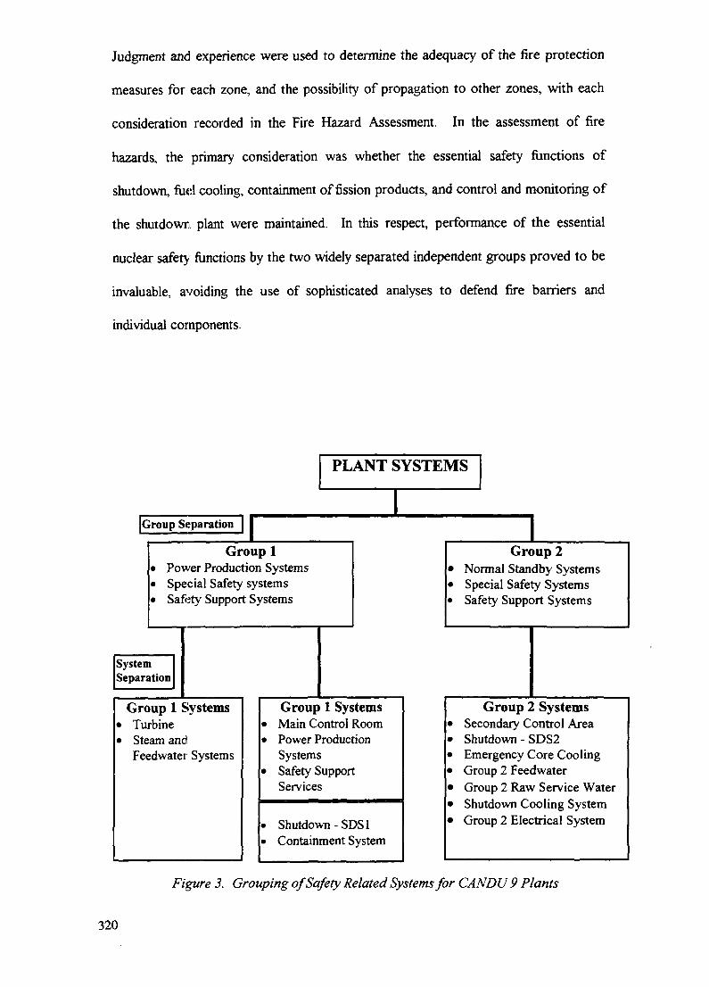
Judgment and experience were used to determine the adequacy of the fire protection
measures for each zone, and the possibility of propagation to other zones, with each
consideration recorded in the Fire Hazard Assessment. In the assessment of fire
hazards, the primary consideration was whether the essential safety functions of
shutdown, fuel cooling, containment of fission products, and control and monitoring of
the shutdown plant were maintained. In this respect, performance of the essential
nuclear safety functions by the two widely separated independent groups proved to be
invaluable, avoiding the use of sophisticated analyses to defend fire barriers and
individual components.
PLANT SYSTEMS
JGroup Separation | |
Group 1Power Production SystemsSpecial Safety systemsSafety Support Systems
SystemSeparation
Group 1 SystemsTurbineSteam andFeedwatet Systems
Group 2Normal Standby SystemsSpecial Safety SystemsSafety Support Systems
Group 1 SystemsMain Control RoomPower ProductionSystemsSafety SupportServices
Shutdown - SDS1Containment System
Group 2 SystemsSecondary Control AreaShutdown - SDS2Emergency Core CoolingGroup 2 FeedwaterGroup 2 Raw Service WaterShutdown Cooling SystemGroup 2 Electrical System
Figure 3. Grouping of Safety Related Systems for CANDU 9 Plants
320
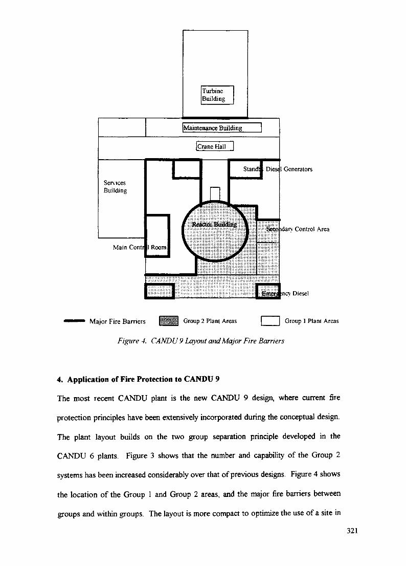
TurbineBuilding
Dies* 1 Generators
Seoo idarv Control Area
:ncv: Diesel
Major Fire Barriers Group 2 Plant Areas Group 1 Plant Areas
Figure 4. CANDU 9 Layout and Major Fire Barriers
4. Application of Fire Protection to CANDU 9
The most recent CANDU plant is the new CANDU 9 design, where current fire
protection principles have been extensively incorporated during the conceptual design.
The plant layout builds on the two group separation principle developed in the
CANDU 6 plants. Figure 3 shows that the number and capability of the Group 2
systems has been increased considerably over that of previous designs. Figure 4 shows
the location of the Group 1 and Group 2 areas, and the major fire barriers between
groups and within groups. The layout is more compact to optimize the use of a site in
321
a multiunit configuration, and to enable the safety related systems to be protected
against site related events. The layout also improves the separation of safety related
equipment from fire hazards (e.g. the main standby generators and electrical buses are
located within the reactor auxiliary building), the separation of redundant components
within systems, and the minimization of combustible materials in the area of safety
related systems. This is backed up by well defined fire barriers, fire detection in all
plant areas, and automatic fire suppression in all plant areas except those continuously
occupied and in the reactor building. A seismically qualified fire water supply is
provided for the reactor building and the Group 2 area of the plant containing essential
safety related equipment credited in the seismic event. A comprehensive Fire Hazards
Assessment and Probabilistic Safety Assessment for internal fires will be completed
during the detailed design, providing extensive documentation for the plant operating
staff for their fire protection program.
5. Conclusion
The evolution of fire protection practices in CANDU plants has mirrored the
development of fire protection principles and practices that has taken place
internationally, and the CANDU design has benefited from the participation in, and
guidance of, the IAEA initiatives for nuclear power plants. The formal Fire Hazard
Assessments for current CANDU plants have contributed to the improvement of the
fire protection design features, and provide extensive information to the operating
plant as a basis for their fire protection program.
REFERENCE
[1] LEE, S.P., Fire Protection for the CANDU 3 Nuclear Power Plant, IAEA-SM-305/54 (Proc. Int. Symp. On Fire Protection and Fire Fighting in NuclearInstallations), Vienna, 1989.
322

IAEA-SM-345/8
SAFETY IMPROVEMENTS MADE AT THE LOVIISANUCLEAR POWER PLANT TO REDUCE FIRE RISKSORIGINATING FROM THE TURBINE GENERATORS XA9847530
T. VIROLAINEN, J. MARTTILA, H. AULAMORadiation and Nucler Safety Authority,Helsinki, Finland
Abstract
Comprehensive upgrading measures have been completed for the Loviisa Nuclear Power Plant(modified VVER440/V213). These were carried out from the start of the design phase and duringoperation to ensure safe plant shutdown in the event of a large turbine generator oil fire. Thesemodifications were made mainly on a deterministic basis according to specific risk studies and fireanalyses. As part of the probabilistic safety assessment, a fire risk analysis was made that confirmedthe importance of these upgrading measures. In fact, they should be considered as design basismodifications for all VVER440 plants.
1. INTRODUCTION
Operational experience has proved that disturbances of turbine generator systems often affectoverall plant safety. Many disturbances have led to accidents causing accidents and extensivedamage in turbine halls and in their vicinity. The most severe consequences have been loss ofhabitability of the control room, loss of residual heat removal and total loss of electrical powerfor a longer period.
The frequency of events originating from the turbine generator is much higher than initiallyestimated. The most serious consequences of turbine generator failures seem to be fires, whichhave a very high occurrence rate. For instance in VVER-440 plants, turbine generator damagecan lead to loss of main feed water, emergency feed water and the primary circuit residualheat removal systems which are situated in the turbine hall.
This paper is based on experiences of the fire and risk analyses conducted by STUK and thePSA analysis conducted by IVO as well as the safety improvements implemented at LoviisaNPP. In this paper implemented improvements are presented and also new potential proposalsare considered.
2. THE RISKS OF TURBINE GENERATOR SYSTEMS
In the turbine hall of a VVER-440 nuclear power plant the following safety-related systemsare typically located:
• main feed water system• emergency feed water system• residual heat removal system• steam lines including safety and isolation valves.
323

At the original VVER-440 plant, loss of these systems causes the loss of heat removal via thesecondary circuit which is needed for the primary circuit cooling. Many improvementshave been carried out to ensure heat removal from steam generators.
At Loviisa NPP (a modified VVER-440/V213 plant) buildings connected to the turbine hallare (fig. 1):
• control building• sea water pumping plant of Loviisa-1• demineralisation plant.
Especially the control building is important for plant safety. Electrical rooms (I&C, accumu-lators, switchgears) and cable rooms are situated inside the same building (fig. 2). The mainsteam and feed water pipes and valves are located on the top of the control building. Inanticipated transients heat removal by the turbine condenser and the main feed water systemmay be lost. In this situation the residual heat can be removed from the primary circuit by thefeed and bleed functions of the steam generators:
• feed by the available emergency feed water system• bleed by the controlled main steam valve blow• isolation of the main steam and main feed water lines to maintain the pressure and the
water level in the steam generators.
The equipment needed for these feed and bleed functions are vital for the plant's safety andthey should be separated from the turbine hall.
1 400 kV switchyard2 diesel building
1 3 main transformers. _ 4 storage tanks of demineralizated water
^2 i 5 sea water pumping plant6 fire water pumping plant
4 ^ XX 3 7 turbine hall' X j : 8 control building
— 9 demineralization plant5 10 office building
l f t Q ' \_\J 6 11 emergency feed water pumping plantM and excess water tank area
11 Vi.^ \ '' \ ^ laboratory building""_ 14 ~ j 4 13 roofed tank area
12 i n \ / " 14 reactor building13 - . _. 15 service building
, , 16 auxiliary building1" 17 17 social building
J 18 spent fuel storage18 19 emergency water tank
Figure 1. Power plant area of Loviisa NPP. Thicker line between turbine halland control room building is fire wall.
Almost all of the plant safety systems are cooled by the service water system which is locatedin the sea water pumping plant together with the turbine condenser cooling water pumps (bigsea water pumps). Of these safety systems, the residual heat removal system for unit cold shutdown and the conventional intermediate cooling system for cooling of the feed water and
324
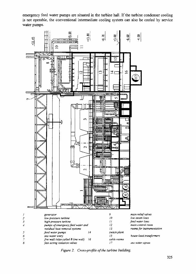
emergency feed water pumps are situated in the turbine hall. If the turbine condenser coolingis not operable, the conventional intermediate cooling system can also be cooled by servicewater pumps.
/234
5678
generatorlow pressure turbinehigh pressure turbinepumps of emergency feed water andresidual heat removal systemsfeed water pumps 14sea water entryfire wall (also called B line wall) 16fast acting isolation valves
910111213switch plant15cable rooms17
main relief valveslive steam linesfeed water linesmain control roomrooms for instrumentation
house-load transformers
sea water egress
Figure 2. Cross-profile of the turbine building.
325

The most significant turbine generator failures are missiles ejected from turbine and fireswhich lead to severe consequences. Turbine generator failure modes, frequencies and riskshave been studied more in the paper "Risks of turbine generators at VVER-440 nuclear powerplants". In this connection it is important to notice that a large oil fire in the turbine hall is apotential risk for all safety-related systems situated in the turbine hall or in its vicinity andtherefore a reason for serious concern.
3. IMPLEMENTED PLANT MODIFICATIONS
Deficiencies in many plant sections have been identified especially in the original lay-outdesign of VVER-440 plants. Insufficient fire compartmentation and component separation aswell as poor fire resistance of structures can be considered as the biggest problems. To im-prove the deficiencies of basic design, many modifications have been already implementedstarting from the design phase and early stages of plant operation. The most significantmodifications have been:
• Installation of sprinkler systems to protect the turbine hall, as a whole area sprinklers fordifferent levels and local sprinklers for oil systems.
• Fire insulation of the load bearing steel structures of the turbine hall and the control build-ing.
• Installation of a fire valve to the governing oil line. The valve will close automaticallywhen the fin; detection system detects a fire in an HP turbine. The closure will trigger aturbine trip due to a pressure drop of the regulating oil.
• Adding the option of feeding water to the steam generators from the primary circuit make-up water pumps.
• Relocation of the generator hydrogen cooling system's hydrogen station and lines to amore safe place.
• Construction of a fire wall (F180) between the turbine hall and the control building (socalled B line wall, fig. 2). The fire wall separates the steam and feed water lines and valvesfrom the turbine hall into an individual fire compartment to protect them against turbinehall fires. The wall is constructed to withstand the potential collapsing of the roof. Also,smoke and heat removal hatches were added.
• Setting up a new back-up emergency feed water system. The system is totally independentof the feed water and emergency feed water systems in the turbine hall. The system'spumps are diesel-driven and they are able to supply water directly to the bottom of thesteam generators (to four of six).
• The cooling and ventilation systems of the control building were improved (also againstfires in the turbine hall).
• Relocation and compartmentation of safety-related cables and equipment in the turbinehall.
• Fire protection improvements at the governing oil system of the turbine by-pass valves (onthe top of the control building).
• Building up a new, separate fire water pumping station, which consists of three dieseldriven water pumps, water tanks, supply lines and valve stations.
• Replacement of primary circuit safety valves with new type Power Operated Relief Valves(PORVs), which make the primary circuit feed and bleed function possible.
• Improvements in the generator's hydrogen cooling and sealing oil systems.
326

All the improvements mentioned above have been reported widely in STUK's quarterlyreports, "Operation of Finnish nuclear power plants".
The latest improvements concern the hydrogen cooling and sealing oil systems, which havebeen modified in the annual maintenance outages in 1996 and 1997. The main aim has been toimprove the operational safety of these systems and also to modify the systems to meet thecurrent standards. One reason for the modifications was also the small hydrogen fire at unittwo on 17 January, 1996. The fire resulted from a leaking liquid detector. The implementedmodifications during the year 1996 were:
changing of liquid detectors and respective valvespotential equalisation of sealing oil system pipes.
During the 1997 maintenance outage a lot of changes were made in the hydrogen coolingsystem of Loviisa-1. Because of the changes the system had to be redesigned and built upalmost from the beginning. Mostly due to the lack of time modifications were made only forone generator. The objectives of the changes were:
• to move the valve cabinet of the cooling system to adequate distance, as also required bynew safety standards, from the generator's electric systems
• to simplify the system and thus enhance its operability by deleting unnecessary valves andpipes
• to replace the flanged joints of pipes and valves with welded joints where possible• to facilitate nitrogen feeding to the generator during the hydrogen dryer's regeneration.
4. PROPOSALS TO DECREASE THE RISK RESULTING FROM TG FAILURESIN FUTURE
Proposals are divided into three groups. Division has been made by figuring out, how de-manding the improvements are and how much the planning and the implementation wouldtake time. The purpose has been to evoke discussion between the utility and the authorityabout possibilities to improve safety of turbine generator system. Most of the proposals areaimed to decrease the frequency of turbine generator failures or their consequences.
4.1. Short term improvements
Short term improvements concern the plant's instructions, tests and staff training. Despitetheir easy implementation, the improvements may be significant for the systems' operationalsafety. The most important subjects are:
• operational instructions• instructions for disturbances and emergency situations• tests and instructions for testing• simulator training of operators
The applicability of the plant's instructions has been proven in the course of time. Mistakesand shortcomings in the instructions have been handled with the operation group manager.
The simulator training programs have not contained enough turbine generator events consid-ering their frequencies and significance.
327
4.2. Medium term improvements
Medium term proposals concern mainly the construction and instrumentation of the turbinegenerator systems. Modifications can be performed within a rather short time period and withreasonable economical investments. The most important subjects for proposals are:
• vibration monitoring system• hydrogen cooling system.
4.2.1. Vibration monitoring system
The length of time delays, the small quantity of measurement sensors and the lack of auto-matic turbine trip due to high vibration levels are the biggest drawbacks of the present-dayvibration monitoring system. To improve the situation a modernisation project has alreadybeen started at the plant. It has been found out that modern monitoring systems with versatileand fast analysing resources are very good instruments for the surveillance of the turbinegenerators. However, the automatic trip function has not been included in the plans in thisphase.
The attitude against the automatic trip function is not based on operational experience. Such afunction is generally used all over the world. In Finland, Olkiluoto NPP has very good experi-ence from it. Any problems, such as false trips, have not occurred. It is important to notice theenormous benefits of an automatic trip function: it is almost the only way to drive the turbinegenerator down quickly and safely in case a sudden unbalance due to the breakage of therotating parts occurs.
4.2.2. Hydrogen cooling system
The hydrogen cooling system modifications have obviously improved the system's safety.The most significant weaknesses that were not covered by the modification plans are thoseconnected to the: hydrogen dryer, the analysers of purity and humidity and the lay-out of thecomponents.
The problem of the silica gel dryer is its inefficiency. It is impossible to attain the recom-mended level of hydrogen humidity set by the generator's manufacturer by using the presentdryer. Especially after the maintenance shut-down, the humidity may exceed the permittedvalue considerably. The key to the humidity problems would be to replace the dryer with amore efficient model.
The humidity of the hydrogen is controlled by laboratory analysis once a month. If the hu-midity increases for instance due a water leak from the hydrogen cooler into the generator, theobservation may fail for a long time. Therefore an on-line humidity analyser should beinstalled in the cooling system.The best alternative when safety is concerned is that the hydrogen dryer and valves aresituated in a place resistant against fires and explosions, protected with leak monitoring andextinguishing systems. This has proved difficult to be achieved in practice. After all, themonitoring of the hydrogen leaks in the vicinity of the hydrogen dryer and the valves shouldbe the target of the modifications.
328

4.3. Long term improvements
Long term improvement needs consist of very extensive changes in the systems, which willrequire further system and risk studies. A lot of effort has been put forward to find the areas inwhich large modifications would be reasonable for improving safety e.g.:
• improving operational safety of the oil systems• protection of the safety-related systems situated in the turbine hall.
4.3.1. Oil systems
Subjects still unaddressed are:
• vibration monitoring of the oil pipes• supervision of the oil pipes• drainage areas of the oil-leaks• lay-out of systems pipes and components.
4.3.2. Protection of the safety-related systems
Safety-related components situated in the turbine hall have been planned to be protected byusing sprinkler systems and barriers. However, some components are still without adequateprotection. It is important that the protection of the components will be examined under thelight of probabilistic risk analysis.
5. CONCLUSIONS
Many improvements have been carried out at Loviisa NPP (chapter 3). The improvementshave decreased the risk of turbine generator failures considerably. The independent back-upemergency feed water system, the fire separation wall of the turbine hall and other fire safetyimprovements decrease the total core damage risk at Loviisa NPP roughly by a factor 100according to the present PSA model of the plant. The risk of turbine hall fires seems to be onthe same scale of magnitude as the influences of many other initiating events. This argumentis supported by a fire risk analysis, which has been completed by the utility and delivered toSTUK for inspection. A fire in the turbine hall, especially when resulting from a turbinegenerator mechanical breaking, is still one of the most considerable contributors to coredamage. There are still some areas where changes are necessary and cost-efficient. Such areaswould be e.g. the turbine generator vibration monitoring, the generator hydrogen cooling, theshort term proposals indicated above and the protection of safety-related systems.At some other VVER-440 plants the situation is much worse. First of all, the lay-out isusually weaker than at Loviisa. The most important weakness is the unfavourable location ofturbine generators. Lay-out modifications are mostly impossible to carry out, but with someimprovements the situation could improve significantly. The most effective improvementsreducing core damage risk are:
• building up an independent back up emergency feed water system• construction of a fire wall (F180) between the turbine hall and the control building and
valve gallery• insulation of load bearing steel structures of the turbine hall and the steam and feed water
valve gallery
329

• installation of sprinkler systems to protect the turbine hall• building up a modern fire water pumping station.
At least the first two improvements are extremely important for reactor residual heat removaland these systems can be recommended for all VVER-440 plants. Without improvements thecore damage risk may be two decades higher than in Loviisa and the significance of theturbine hall is emphasised accordingly. After these basic design improvements have beenmade, safety can be further improved by utilising the proposals presented in chapter 4.
330
IAEA-SM-345/45
Invited Paperi mil Him
UPGRADING OF FIRE SAFETY XA9847531IN INDIAN NUCLEAR POWER PLANTS
N.K. AGARWALNuclear Power Corporation Ltd,Mumbai, India
Abstract
Indian nuclear power programme started with the installa-tion of 2 noe. of Boiling Water Reactor (BWR) at Tarapur (TAPSI & II) of 210 MWe each commissioned in the year 1969. ThePressurized Heavy Water Reactor (PHWR) programme in the countrystarted with the installation of 2x220 MWe stations atRawatbhatta' near Kota (RAPS I & II) in the State of Raj as thanin the sixties. At the present moment, the country has 10stations in operation. Construction is going on for 4 moreunits of 220 MWe whereas work on two more 500 MWe units isgoing to start soon. Fire safety systems for the earlier unitswere engineered as per the etate-of-art knowledge availablethen. However, there have been several developments 6ince thenin the understanding of the subject of Fire Safety. Newengineering information by way of standards and codes fromvarious national as well as international organizations,materials of construction for cables, fire barriers etc,construction practices, surveillance requirements, detectionsystems have since been available in the market. Feed backavailable from several fire incidences within as well asoutside the country have taught number of lessons. Theengineering design as well as the installation of the existingfire safety system at the plants need to be reviewed withreference to these in order to ensure better protection againstfire incidences.
The need for review of fire protection systems in theIndian nuclear power plants has also been felt since longalmost after Brown's Ferry fire in 1975 itself. Task forcesconsisting of fire experts, systems design engineers, O&Mpersonnel as well as the Fire Protection engineers at the plantwere constituted for each plant to review the existing firesafety provisions in details and highlight the upgradationneeded for meeting the latest requirements as per the nationalas well as international practices. The upgradation at one ofthe two unit6 of a plant was done during rehabilitation after afire incidence on the unit. The fire protection system designfor the 4 units under construction as well as the 500 MWe unitsyet to be taken up for construction was already reviewed tomeet the current requirements/standards.
The recommendations made by three such task forces for thethree plants are proposed to be reviewed in this paper. Thepaper al6o highlights the recommendations to be implementedimmediately as well as on long-term ba6i6 over a period oftime.
331

1.0. INTRODUCTION
Electricity generation through the nuclear route is a veryimportant option for meeting the energy requirement of anycountry. Although presently in India, nuclear energycontributes only around 2% of the total electricitygenerated in the country, in view of the environmentalproblems associated with the use of fossil fuel6 as wellas limited availability of these in the immediate future,nuclear energy becomes a very important alternative forproducing electric energy.
Indian nuclear power programme started with the installa-tion of 2 nos. of Boiling Water Reactors (BWRs) at Tarapur(TAPS "I & II) of 210 MWe capacity each in the year 1969.The programme is based on Pressurised Heavy Water Reactors(PHWRs). The first two PHWR units of 220 MWe capacityeach were installed at Rawatbhatta near Kota (RAPS I & II)in the state of Rajasthan in the year 1973. At thepresent moment, the country has 10 stations in operation.Construction is in progress at 4 more units of 220 MWeeach. Work on 2 units of 500 MWe each is going to startsoon. Details of the Indian nuclear power programme isgiven in annexure-I.
Fire safety systems in the units installed initially wereengineered as per the state-of-art knowledge availablethen. There have been continuous advancements in thefield of fire safety engineering and several developmentsin the understanding of the subject. It has thereforebeen necessary to continuously review the engineeringdesign as well a6 installation of the existing fire safetysystems at the plants and upgrade these with reference tothe knowledge available now in order to ensure betterprotection against fire incidents.
The need for review of fire protection systems in theIndian nuclear power plants (NPPs) also has been feltsince long almost after the Brown's Ferry fire in 1975itself. This incidence caused an almost global awarenessto look into the subject of fire safety afresh. Newengineering information by way of standards and codes fromvarious national as well as international organisations,better materials of construction for cables, fire barriersetc., construction practices, surveillance requirements,detection systems have since been available in the market.Feed back available from several fire incidents within aswell as outside the country has taught lessons to learn.
The exercise for reviewing the existing fire protectionsystem engineering to identify the weaknesses in theexisting systems at the country's NPPs with a view toupgrade the fire safety was taken up in a very systematicmanner. Details of these studies are discussed in theensuing paragraphs.
332
2,0. PHILOSOPHY OF FIRE SAFETY REVIEW
The fire safety syeteme for the plants were designed to bein general conformity with the National Fire ProtectionAssociation (NFPA) Standards of USA, being most commonlyfollowed globally. Fire Protection Safety Guide 50-SG-D2issued by IAEA, fire protection standards 1.120 of D.S.Nuclear Regulatory Commission (which was later onsuperseded), Canadian, French & German Standards gavedetailed guidelines and latest requirements for the fireprotection system design. Atomic Energy Regulatory Board,which is the regulatory body for the Indian nuclearinstallations also issued Fire Protection Standards andthe design safety guide is under issue.
The r.eview of the fire safety provided at the variousNPPs was planned to be conducted through knowledgeablepersons having sufficient knowledge in the field of firesafety, engineering of the systems provided at the plant,knowledge about the codes, knowledge about electrical aswell as control and instrumentation systems designed forthe plants etc. Dedicated task forces were constitutedfor the individual plants who were required to look intothe detailed provisions at the respective plants, analyse,evaluate and then identify weaknesses in the specificareas. The task forces were also expected to carry outhazard analysis for the critical plant areas.
3.0. PHILOSOPHY OF FTRE SAFETY TIPGRADATTON
After reviewing the fire protection systems provided atthe operating stations, the weaknesses are identified.The reports produced by the task forces are formallydiscussed in the respective Station Operations ReviewCommittees (SORC) appointed for each station. Once therecommendations are finalised, these are then taken up forimplementation.
Depending upon the constraints in the implementation, theaction plan is decided to execute these upgradingactivities on short term or long term basis. Theconstraints could be by way of working out engineeringdetails and getting these designs cleared through theregulatory authority, procurement of materials, need for astation shutdown for short or long duration etc.
Although it will be desirable to have the fire protectionsystem design as well as the plant layout to meet thelatest standards, practically it is not possible. Thishas been experienced even globally also. US N.R.C. in May1976 issued Branch Technical Position, Auxiliary and PowerConversion Systems Branch 9.5-1 (BTP A - PCSB 9.5-1)"Guidelines for Fire Protection of Nuclear Power Plants"which applied to plants licensed for construction afterJuly 1, 1979. In order to establish an acceptable levelof fire protection at the older, operating plants withouthaving a significant impact on plant design, constructionor operation, the NRC modified the guidelines in the
333
original BTP in September 1976 and issued Appendix A toBTP 9.5-1 "Guidelines for Fire Protection for NuclearPlants Docketed prior to July 1, 1976".
In India, although no codes have been issued for fireprotection acceptable levels in respect of plantsconstructed as per older designs exclusively, thephilosophy of defence-in-depth wa6 applied to each case onits merit.
For the new plants, adequate provisions have been made inthe designs to meet the requirements of the availablenational and international codes, some of which are asunder:-
IAEA Safety Series - Fire Protection in Nuclear PowerNo. 50-SG-D2 Plants.
NEC Guide 1.75 - Physical independence of Systems.
IEEE 384 - Criteria for Independence of ClassIS equipment and circuits.
NRC 10 CFR 50 - Fire ProtectionAppendix B.
NFPA Codes
AERB/S/IRSD-I - Standard for Fire Protection Systemsof Nuclear Facilities, issued byAtomic Energy Regulatory Board.
Fire Protection Codes & Standards issued by Bureau ofIndian Standards.
The Regulatory authority is also bringing out Safety GuideNo. AERB/SG/D-4 on "Protection Against Fire in NuclearPower Plants" shortly.
As in the case of NRC, for upgrading at Indian plants alsoin respect of 3 hours fire barriers everywhere, a decisionwas taken that wherever automatic suppression anddetection systems have been provided, a 1 hour ratedbarriers can be considered an equivalent level ofprotection to that provided by a 3 hour barrier withoutsuppression or detection between redundanttrainfs/equipment.
4.0. OPGRADATION OF FIRE SAFETY IN THE OPERATING NPPR
As has been discussed earlier, in order to review the firesafety measures provided in the existing operating plantsand then identify the weaknesses in order to upgrade thefire safety systems, task groups were constituted for eachof the operating plants. The task groups after reviewingthe systems and combustibles present in the various areas
334
in details, and carrying out a fire hazard analysis,put forward recommendations which are discussed in thesucceeding para.
4.1. Tarapur Atomic Power Station
TAPS being the oldest station, weaknesses wereidentified by the ta6k force. The reports of the taskforce is still under finalisation. However, thefollowing recommendations need attention:-
4.1.1. Recommendations
4.1.1.1. £ab_l££
1. fire retardant coating with a minimum fire rating of30 minutes needs to be applied to the horizontal aswell as vertical cable runs. All horizontal runs ofcables to be coated for 2 meters length at theinterval of 6 metres. Vertical cable runs could becoated on their entire length between floor andceiling.
2. For important safety related equipment, cablesshould be segregated, if not already done so.
3. As far as possible, all future procurement ofinstrumentation and electrical cables should be ofFire Retardant Low Smoke (FRLS) type.
4.1.1.2.Ventilation
1. Wherever not provided, ventilation fans for the mainplant buildings should be interlocked with firedetection system to trip on detection of smoke/flame.
2. Smoke evacuation systems should be provided in cablespreading room. Proper procedures need to bewritten for exhausting 6moke from the Turbinebuilding through roof exhausters.
4.1.1.3.Fire Barriers
Provision of fire barriers need to be reviewedparticularly in respect of the safety relatedequipments. Wherever not provided, Fire barrier ofappropriate fire ratings need to be installed.
4.1.1.4.Fire Detection & Suppression Systems
The fire detection system provided is of old design.Recommendations have been made to consider upgradingthe existing system with the later versions byinstalling addressable detectors. Also review ofexisting detector coverage with diverse type detectors
335
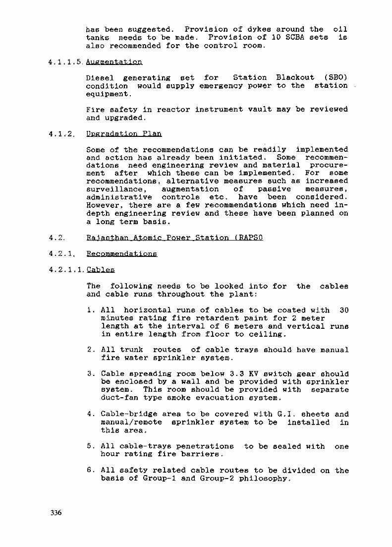
has been suggested. Provision of dykes around the oiltanks needs to be made. Provision of 10 SCBA sets isalso recommended for the control room.
4.1.1.5.Augmentation
Diesel generating set for Station Blackout (SBO)condition would supply emergency power to the stationequipment.
Fire safety in reactor instrument vault may be reviewedand upgraded.
4.1.2. Degradation Plan
Some of the recommendations can be readily implementedand action has already been initiated. Some recommen-dations need engineering review and material procure-ment after which these can be implemented. For somerecommendations, alternative measures such as increasedsurveillance, augmentation of passive measures,administrative controls etc. have been considered.However, there are a few recommendations which need in-depth engineering review and these have been planned ona long term basis.
4.2. Raiasthan Atomic Power Station (RAPSQ
4.2.1, Recommendations
4.2.1.1.
The following needs to be looked into for the cablesand cable runs throughout the plant:
1. All horizontal runs of cables to be coated with 30minutes rating fire retardent paint for 2 meterlength at the interval of 6 meters and vertical runsin entire length from floor to ceiling.
2. All trunk routes of cable trays should have manualfire water sprinkler system.
3. Cable spreading room below 3.3 KV switch gear shouldbe enclosed by a wall and be provided with sprinklersystem. This room should be provided with separateduct-fan type smoke evacuation system.
4. Cable-bridge area to be covered with G.I. sheets andmanual/remote sprinkler system to be installed inthis area.
5. All cable-trays penetrations to be sealed with onehour rating fire barriers.
6. All safety related cable routes to be divided on thebasis of Group-1 and Group-2 philosophy.
336

4.2.1.2. Vent Hat ion Systems
1. R/B exhaust ventilation should have a spare bank ofprefliter and absolute filter common to both theunits in some other area.
2. One remote/manual operated damper to be provided inR/B exhaust duct at 1263' floor for purging smokefrom boiler room.
3. All presently installed fusible link type firedampers to be replaced with air operated type firedamper of one hour fire rating for formation of firezones.
4. Control room, control equipment and MCC room shouldhave a separate fan duct type 6moke evacuationsystem and control room make-up air should be takenfrom T/B ventilation duct instead of turbinebuilding ventilation duct.
5. Control room and control equipment room R-l and R-2should have isolation damper in supply and returnduct to contain the smoke in the affected area.
4.2.1.3. Fire Dtection and Protection System
1. Presently installed fire detection and alarm systemto be replaced with addressable type fire detec-tion and alarm system having total 209 addresspoints of various type6 for each unit.
2. Areas out6ide operating island should also have afire detection and alarm system having total of 100smoke detectors.
3. Main oil tank of turbine should be provided with C02dousing system inside tank and gravity oil drainingsystem to drain MOT oil to outside turbine building.If it is not feasible, then provide draining intodirty oil purifier tank inside T/B.
4. Hydrogen leak detectors to be installed in turbinebuilding near generator and battery room.
5. To meet the station black-out condition due to fire,RAPS-1&2 fire water header may be connected to RAPP-3&4 fire water header.
6. Fire hydrants outside operating island to beconnected to fire water system.
4.2.1.4. Fire Barriers
1. All doors inside reactor building, control room,battery room, DG room, MG room should be tested forfire-rating to meet the fire rating requirement ofone hour.
337
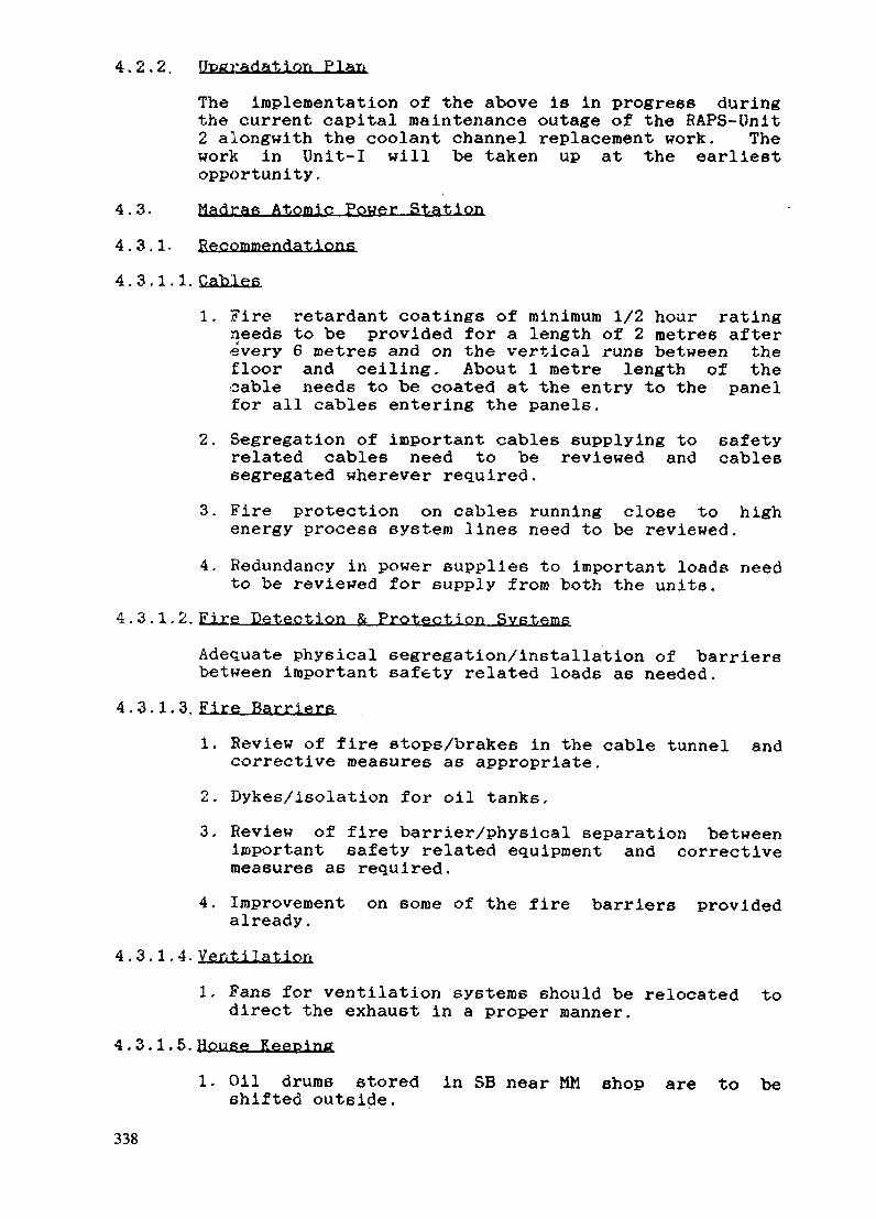
4.2.2. Ut>gradatiort Plan
The implementation of the above is in progress duringthe current capital maintenance outage of the RAPS-Unit2 alongwith the coolant channel replacement work. Thework in Unit-I will be taken up at the earliestopportunity,
4.3- Madras Atomic Power Station
4.3.1- Recommendations
4.3.1.1.
1. Fire retardant coatings of minimum 1/2 hour ratingneeds to be provided for a length of 2 metres afterevery 6 metres and on the vertical runs between thefloor and ceiling. About 1 metre length of thecable needs to be coated at the entry to the panelfor all cables entering the panels.
2. Segregation of important cables supplying to safetyrelated cables need to be reviewed and cablessegregated wherever required.
3. Fire protection on cables running close to highenergy process system lines need to be reviewed.
4. Redundancy in power supplies to important loads needto be reviewed for supply from both the units.
4.3.1.2. Fire Detection & Protection Svfitfimfi
Adequate physical segregation/installation of barriersbetween important safety related loads a6 needed.
4.3.1.3. Fire Barriers
1. Review of fire stops/brakes in the cable tunnel andcorrective measures as appropriate.
2. Dykes/isolation for oil tanks.
3. Review of fire barrier/physical separation betweenimportant safety related equipment and correctivemeasures as required.
4. Improvement on some of the fire barriers providedalready.
4.3.1.4. Ventilation
1, Fans for ventilation systems should be relocated todirect the exhaust in a proper manner.
4.3.1.5. House Keeping
1. Oil drums stored in SB near MM shop are to beshifted outside.
338

4.3.1.6. Supplementary Control Room
1. The supplementary control room as alreadyrecommended by MAPS should be provided.
4.3.1.7. Redundancy
1. The field flashing unit is common for both MG1 & 2.Independent field flashing units should be providedfor each MG set.
It may be noted that the above are only 6ome of themajor recommendations. Wherever further weaknesses arenoted during any stage, the 6ame should be upgraded.
4.4. Narora Atomic Power Station fNAPS^
NAPS Unit I had a major fire on March 31, 1993. Thefire resulting from failure of LP turbine bladesstarted from the Turbine hall and spread upto controlequipment room through ineffective fire barriersdamaging several cables and ultimately resulting into astation blackout condition. The reactor was shutdownmanually. Fortunately there was neither any damage tothe reactor, nor spread of radioactivity nor death ofany human being due to the incident.
Extensive modifications were carried out in the NAPS-Iafter the fire incidence during its rehabilitation.
4.4.1. Passive Fire Protection
a) Segregation of power and control cables of safetyrelated equipments which are required to beavailable during and after fire.
b) Some of the local control panels are relocated tothe easily accessible areas during fire.
c) LTG panels for both units have been physicallyseparated.
d) Hydrogen charging station i6 relocated outside ofthe Turbine building. Hydrogen leak detectionsystem has been introduced.
e) The Fire Water System in nuclear power plantsperforms additional duty as heat sink. Duringstation blackout fire water is injected to steamgenerators through manually operated valves. Thesevalves were relocated from inside reactor buildingto the outside to provide better access duringemergency.
4.4.2. Fire Isolation
a) Ventilation system has been reviewed from thepoint of view of fire spread and isolation of area
339

under fire. It is retrofitted with about 90 firerated dampers in several strategic areas likeelectrical equipment rooms, control room, controlequipment room etc. to isolate in the event of fire.Fire dampers of minimum one and half hour rating asper UL-555 in accordance with NFPA-90A and IAEASafety Guide 50-SG-D2 are considered.
b) All cable penetrations are reviewed and upgradedwith fire rated cable penetrations and fire stops.Additional fire rated stops have been installed.
c) Additional Fire barriers have been considered aspermitted by the available space.
4.4.3. Minimising Combustibles
a) For safety related service the use of Fire Survivalcables is considered. The other cables are upgradedto Fire Besi6tant Low Smoke (FRLS) type. AllControl and power cables have been given fireretardant treatment.
b) Provision to drain the main oil tank in case of fireto an outside storage tank to minimize the fire loadis considered.
4.4.4. Elimination of ignition source
Oil collection trays are provided beneath the probableleakage points in the oil piping. Local barriers toseparate oil piping from cables and hot piping areprovided.
4.4.5. Active Fire Protection
a) Existing sprinkler system is extended to cover theseal oil piping and turbine bearings. Additionalsprinklers are planned for area6 having higher cableconcentrations like Cable Bridge, PHT passages andMassanine floor passage.
b) Addition of microprocessor based detection systemhaving individually addressable detectors in crosszoning to ensure earliest warning of fire andminimization of false alarms. This alsoincorporates the controls for actuation of firedampers & tripping of exhaust and ventilationsystem. Multiple fire detection systems have beenconsidered for critical areas.
4.4.6. Control Room Habltabilitv
Special emphasis has been given to the control roomhabitability during emergency. Operators are trainedto use mask air stations, breathing apparatus, portable6moke exhausters and emergency lights which areprovided along with portable Halon extinguishers. An
340

alternate path is provided for fresh air intake forcontrol room ventilation during emergency. Additionalcontrol for stopping and starting of smoke exhaustersand AHU'6 feeding to control room is provided incontrol room. Gravity closing door6 are consideredbetween control equipment room and control room tofacilitate their opening only on requirement.
4.4.7. Fire Protection Management
To improve the fire protection management, followingprovisions are considered.
1. A regular fire prevention plan is envisaged to takecare of regular inspection and maintenance of firebarriers, fire sealing and fire retardant coatings.
2. Marking of Escape routes and emergency exits toshow the way out for safety of personnel.
3. A Fire Fighting Preparedness Plan is envisaged forevery plant area. This involves fire drills andtraining to the operators, house keeping and recordof the safety procedures.
4. Pre fire plan for training and actual fire fighting.
5. Inviting constructive safety suggestions from plantpersonnel. This helps to maintain safety awareness,reduce combustibles and improve fire safety.
6. Upgradation of manual fire fighting crew andequipment.
7. Training of fire fighting crew to identify the plantareas, the inventory of combustibles and theirevacuation requirements.
4.4.8. Implementation in Unlt-2
Most of the above modifications have been carried outin NAPS Unit-2 also.
5.0. UPGRADING THE FIRE PROTECTION SYSTEMS
Implementation of upgrading efforts posed its own shareof problems. Some of the problem areas were as under:-
1. Lack of space available in the plant for reroutingor providing physical separation.
2. Difficulty in segregating cables for variousvoltages and belonging to separate trains.
3. Lack of standardisation in the fire . resistantproperties for cables.
341

4. Availability of adequately fire rated fire barriers.
5. Availability of fire rated fire doors, dampers etc.
6. Economic considerations
Lack of space for physical separation of cables/equipment wa6 a problem that could not be easily solvedin the older plants. Also introduction of physicalbarriers/partitions of appropriate fire rating could meanrestriction of access during operation and maintenance ofthe equipment.
Lot of development efforts were put in to standardise onfire resistance coatings for cables, fire barriers ofsuitable fire ratings, good quality cables of appropriatelow smoke as well a6 fire survival quality. Experimentswere conducted in-house at our plants as well as at someof the established national laboratories like CentralBuilding Research Institute (CBRI) at Roorkee. Theseefforts paid dividends and we were able to get thedesired quality of cable coatings and barriers.
On the cables already laid out in thick bunches,installation of fire barriers at area penetrations alsoposed challenges and installation procedures had to bedeveloped to suit each penetration.
Considerable difficulty is being experienced in theavailability of adequately fire rated doors and dampers.Testing for the fire resistance quality to meetinternational standards e.g. ASTM E-152/NFPA 252 fordoors or OL 555 for dampers has not been easy always.Doors and dampers tend to become very heavy in weight andpose difficulties in installation and operation.
Although no compromise on economic considerations forfire safety can be made, the expenses involved do becomean important criterion in carrying out the upgradingprogrammes. Again here al6o, this i6 not only ourexperience but true globally. As such the upgradingprogrammes need to be reviewed for fire safetyenhancement vis-a-vis economics involved.
6.0. CONCLUSION
To conclude
1. Indian nuclear power programme has attained maturityin all areas.
2. Fire Safety in the older plants has been reviewedthrough constitution of task forces. Therecommendation of these task forces are reviewed fromregulatory point of view.
3. Difficulties have been experienced in the availabilityof adequately fire rated equipment for the plants.
342

4. Upgrading has been done for the fire safety at theoperating plants consistent with the defence-in-depthphilosophy.
5. Review of fire safety system design is an ongoingprocess in our nuclear programme.
6. Fire Safety in the new plants has been provided asper the current international practices.
7. Fire Safety in the Indian nuclear power plants isgiven very high priority.
343

Annexure-1NUCLEAR POWER — THE INDIAN PROGRAMME
Onitfi
Tn oneration
TAPS
RAPS
MAPS
NAPP
NAPP
KAPP
KAPP
1 and 2
1 and 2
1 and 2
1
2
1
2
InstalledcapacityCMW(e)]
2 x 160(320)
2 x 220(300)
2 x 170(340)
220
220
220
220
Under Construction
KAIGA 1 and 2
RAPS 3 and 4
2 x 220
2 x 220
Year ofcommissioningand/or comm.operation
1969
1973/1981
1984/1986
1991
1992
1993
1994'
1998/1999
1998/1999
Remarks
Units derated to 160 MWebecause of the downgrad-ing of some equipment.
RAPS-1 derated to100 MWe and RAPS-2 to200 MWe.
MAPS-1 & 2 derated to170 MWe.
NAPS - 1 derated to220 MWe.
PI2
4
2
4
armed
units
units
units
units
X
X
X
X
500
220
1000
500
2
4
2
4
X
X
X
X
500
220
1000
500
2003
2003
Infrastructure alreadydeveloped at TarapurSite.
344
IAEA-SM-345/17
UPDATING OF THE FIRE FIGHTING SYSTEMS ANDORGANIZATION AT THE EMBALSE NUCLEAR POWER PLANT,ARGENTINA
• • • I I ! • • • • • • • • • • • • • • • • • • • • • • • • * > < • • • • ! • • • *
C.F. ACEVEDO XA9847532Safety and Radioprotection Department,Nucleoelectrica Argentina S.A.,Embalse, Cordoba,
Argentina
Presented by J.R. Martorelli
AbstractA brief description is given of the updating carried out at the Embalse NPP after
commissioning, covering the station fire equivalent loads, the station weak points from the fire pointof view, the possible upgrading of systems or technological improvements, early alarm and automaticactions, organizations, education and training, and drills.
1. INTRODUCTION
Embalse NPP, located in the center of Argentina, is a CANDU — design plant of648 MWe, commissioned in 1983.
It belongs to that design generation of the seventies, that's to say, it is more than 25years old. It means that some upgrading was necessary to be done after commissioning;learnings from Browns Ferry and Three Mile Islands arrived too late for this projcet.
On the other hand, world background of recent years showed that fire hazard in nuclearpower plants were greater and more serious than estimated in early days.
2. FIRE ACCIDENTS CHARACTERISTICS
It is known that origin and causes of fire accidents could be of two main sorts:technologial (due to device, equipment or system failure, such as: electric short-circuits or oilspillage on hot surfaces) or human (responsible of fire initiation because of a wrong work orresponsible due to a lack of skill or poor preparedness to cope with the fire).
Probability of fire occurrence because technological causes can be lowered bycorrective and preventive maintenance, routinary tests, automatic alarming and/or actions,systems upgrading, etc.
Human failures can be reduced by training, practice and education.
3. MAIN AREAS FOR IMPROVEMENT
Fire hazard in Embalse NPS was analyzed and seven main areas for improvementswere found: a) Station fire equivalent loads, b) Station weak points from fire point of view, c)Possible systems upgrading or technological improvements, d) Early alarming and automaticactions, e) Organization, f) Education and training, g) Drills.
345
4. STATION FIRE EQUIVALENT LOADS
First of all, housekeeping was emphasized. No unnecessary materials were allowed toremain into the main buildings, that is: reactor bldg., service bldg., turbine bldg., auxiliary bay(electrical distribution area), and Diesels bldg.
Building separation was also emphasized, e.g. oil supply facility was moved out ofturbine building to the oil storage house, specially built for this purpose. The same was donefor inflammable compressed gases, such us hydrogen, acetylene, etc.
Wood, plywood, cardboard, plastics and paper were reduced as much as possible.As a general rule, a very estrict control was established for inflammable materials
handling.
5. STATION WEAK POINTS
A strong search took place at the plant looking for weak points in order to minimize theprobability of fire.
On this field, even slight oil and fuel spillage were eliminated, dust and dirt cleaninggot special attention and open flames were forbidden unless they were essential. Also smokingwas restricted to a few areas where it is permitted.
Chemical fire inhibitors were used where possible, particularly in warehouse forstocked material and low inflammable solvents are in force for cleaning and degreasing.Essential inflammable chemicals are authorized only for particular applications and in limitedquantities. PVC cables (not fire resistant) were protected with an inhibitor covering.Penetrations sealing got also special attention.
Places where fire is likely to occur a redundant fire detection system was installed,such as explosive gases detection for hydrogen in generator area and fuel vapors in Dieselsarea. These systems are in addition to the main fire detection system.
Besides, console of fire detection system was interconnected with security systemconsole, so there is a permanent watching all over the plant by means of TV cameras,explosive gases detectors and smoke detectors. It is necessary to point out that security systemwas installed shortly after the station was built and commissioned. Security officers alsooverhaul the plant, in addition to the operations group, looking for abnormal or dangerousconditions, such as fire.
6. TECHNICAL IMPROVEMENTS
Several improvements were incorporated to the original design and some others arenow in execution, while a bunch of them are still in project.
Improvements already done are, for example: a) The enlarging of security CCTVsysten, with cameras in reactor and service buildings, b) Automatic shut down of ventilationsystem, damper closing and/or Halon flooding as a result of fire detection system activation, c)Halon protection for main and secondary control room, computer room, cable distributionroom, equipment (signals distribution) room and emergency power supply room was alsoadded to the original design, d) Manual high expansion foam and/or light water systeminstalled in reactor building gives a better protection, not present in the original design, e) Inthe same way, a fire resistant screen was installed between normal and emergency water feedpumps, f) Interconnections carried out between fire and process water systems increasereliability of hydrants system, g) Several four inches couplings installed on the fire watersystem allows to connect the fire truck to this system, in order to use the fire truck as a booster
346

pump to increase pressure from 8 kg/cm2 to 40 kg/cm2, this make possible to reach the planthighest point with the water jet. h) Separated warehouse for contaminated material andequipment, i) Halon protected bunker for essential plant documentation, j) Mock-up area forfire fighting practice.
Upgradings now in execution could be: a) CCTV System enlarging (turbine building),b) New protective equipment for fire brigade (garment for high temperature, newly designhard hats, etc), c) Emergency stock room with essential material and equipment foreseen forfire accidents, d) Replacement of methane gas system by P-10 gas (Argon-methane) inradiation monitors.
Some projected upgradings which are still one the desk could be: a) Halonreplacement, b) Water mist fire protection for primary heat transport system main pumps inreactor building, c) High expansion foam system for turbine oil tank in addition to the actualdry-pipe system, d) High expansion foam protection for cable duct in reactor building,e) Doors replacement by stronger ones from fire point of view.
7. EARLY ALARMING AND AUTOMATIC ACTIONS
Permanent survey by means of CCTV allows image change (or movement) automaticdetection and alarming. This will be used first in turbine building monitoring for fire hazard.
If this experience is successful, it will be expanded to Diesels building.In Diesels building, Halon flooding manual system is being studied to be automatic or,
at least, hand operated from main control room.
8. ORGANIZATION
Today, Embalse NPP has six fire brigades composed of operators on shift. Theydemonstrated to be efficient and fast.
Additional fire fighting support organization was formed with personnel which belongsto the radioprotection and safety department, personnel on call and personnelwhich belongs to National Gendarmerie, the armed force which protects the nuclear station,which is located beside the plant.
On the other hand, a coordination was established with external firemen 35 km aroundthe station for the case of a fire at the plant. It was practically checked that in this situation atleast 10 fire trucks could be at the place in about 20 minutes.
9. TRAINING AND EDUCATION
Fire brigades had an initual training and then a permanent retraining twice a year. Thisincludes skill upgrading at the mock-up yard for fire fighting practice.
All plant personnel (including women) receive a theoretical and practical retraining onfire fighting each four years.
External firemen are retrained each four years on the basic knowledge of radiologicalprotection and station characteristics in order to be able to behave safely in case of a fire at theplant.
Additionally, it is considered essential to accomplish with a permanent education ofpersonnel on the way of a safe behavior in all performed activities.
347

10. DRILLS
There are at least six fire fighting drills a year, that means an average of once a year foreach fire brigade on shift. Support groups make also at least a drill per year.
All plant personnel make a practical drill at least once each four year.However., annual nuclear emergency drills often include scenarios complemented with
fire accidents which must be solved by plant personnel and the emergency organization.At least each four years there is a combined drill with external firemen to test the
effectiveness of this coordination.
348
IAEA-SM-345/19
CERNAVODA NUCLEAR POWER PLANT:MODIFICATIONS IN THE FIRE PROTECTION MEASURESOF THE CANDU 6 STANDARD DESIGN XA9847533
V. COVALSCHIRomanian Electricity Authority,Bucharest, Romania
Abstract
Having as purpose the improvement of fire safety at the Cernavoda NPP - both in theprevention and the protection aspects in the case of fire - we implemented some modifications in theCANDU 6 standard design. These improvements are inspired, mainly, from two sources:
- the world-wide achievements in the field of fire protection techniques, introduced innuclear power plants since the middle of 70's, when the CANDU 6 design was completed;the national practice and experience in fire protection, usually applied in industrialobjectives (conventional power plants, in particular).
The absence of any incident may be considered as a proof of the efficiency of the implementedfire preventing and protection measures.
1. INTRODUCTION
In 1979, Romania, an Eastern European developing country, has embarked on a veryambitious nuclear power project with the aim to build at Cernavoda, on the Danube bank, thefirst nuclear plant, supposed to have, finally, 5 units of CANDU 6 type.Romania's choice of the CANDU was based on this technology's outstanding internationalrecord for safety, environmental protection and reactor reliability. Until 1989, the normaldevelopment of the project suffered from the disadvantages of the highly centralisedeconomy, from the decisions taken by the political leaders, sometimes, against technical oreconomical reasons.These aspects caused large delays in completion of the project.After the Romanian revolution of 1989, the circumstances affecting the completion of theCernavoda project have changed. A new development of the project has begun in Decemberof 1990, when a Consortium made up of the Atomic Energy of Canada Limited and theItalian Company ANSALDO working closely with RENEL has established an effective newproject management team.
The unit 1 construction started based on AECL standard design. Since the design had beenprepared, some major incidents occurred: the incident of Browns Ferry NPP, in 1975, ThreeMiles Island, in 1979, Vandellos 1, in 1989 and Chernobyl accident in 1986. Fire protectionhas received serious attention all over the world.
349

2. RELEVANT SUBJECTS OF THE DESIGN UPGRADING
Having as purpose the improvement of fire safety at the Cernavoda NPP - both in theprevention and protection aspects in case of fire - we implemented some modifications in theCANDU 6 standard design. These improvements are inspired, mainly, from 2 sources:
A. The world-wide achievements in the field of fire protection techniques, introducedin nuclear power plants since the middle of 70's, when the CANDU 6 design was completed:
- The development and use of Fire Risk Analysis for the assessment of the protectionmeasures;
- The use of modern addressable fire detection system;- The use in civil works of new materials, which can be easily installed and provide
highly efficient fire protection.B. The national practice and Romanian expertise in fire protection, usually applied to
industrial objectives (conventional power plants, in particular). The traditional approach inthe fire protection design, used in the construction of industrial objectives in Romania,induced design changes at the Cernavoda NPP, too. This approach has its roots in the lack ofconfidence in the action of the active measures (due to the low reliability of the detection andfire suppression systems previously available in Romania), as well as in the relatively lowlevel of the "safety culture" of the operational and maintenance personnel whose preventiveattitude and skills for fire extinction were not enough developed.The Romanian program for upgrading fire protection became substantial due to the missionorganized by IAEA, at the request of the Romanian Commission for the Nuclear ActivitiesControl, our national regulatory board.The IAEA experts pointed out the importance of fire preventing for nuclear safety of anuclear power plant. In fact, the fire protection system was considered as a safety system.Based on the recommendation of the experts, as well as on the provisions of the IAEA SafetyGuide 50 - D2 and the Romanian rules for fire preventing and prevention, we reviewed theCANDU 6 standard design.Our concept is intended to implement the phylosophy of "defence in depth" protectionagainst the hazards of a fire and its associated effects on safety related equipment, with itsthree main objectives:
- preventing fire from starting;- quickly detecting and extinguishing the fire which does start, thus limiting the
damage;- preventing the spread of the fire which has not been extinguished, thus minimizing
its effect on the essential plant functions.
The design of the Cernavoda NPP recognizes fire as a design basis event. The fire protectiondesign is based on one random fire at a time, which may occur at any location in the plant.More conservative than the Canadian philosophy which states that combustible materials aresubject to ignition only whenever a source of ignition is present, our philosophy is base onthe assumption that an ignition may occur even when an important thermal load only ispresent. Therefore, we proceeded to find adequate fire preventing and protection measureswherever the thermal load exceeds 200 MJ/mp. Thus, the first step in preparing firepreventing program was to determine thermal load for each area or room in the nuclear powerplant. This was done in a Fire Risk Analysis. The Fire Risk Analysis performed before theinitial loading of the reactor fuel consists of:
350
- identifying the areas (zone or room) with high thermal load- analyzing of the consequences of fire in such areas, taking into account the presence
of the items important to safety- determining the required fire resistance of fire barriers- identifying cases where aditional fire separation is required- determining of the type of fire detection and protection means to be provided.
Based on this analysis, we establish the following aditional measures:
2.1. Fire Protection of Structural Steel in the Nuclear Service BuildingThe stipulations of the Romanian technical, related to fire resistance require the rating ofcompartment boundary to be the same with the resistance rating of the structural steelassemblies upholded. The AECL design did not observed this requirements. The structuralsteel being unprotected, under fire they would resist only 15 minutes, although uphold wallshave a fire resistance rating of an hour for the top level and two hours for the current levels.Therefore it became necessary to use a fire protection coating on the structural steel in orderto upgrade the level of fire resistance. Depending on the stage of works on site, defferentprotection solutions were used: asbestos spray, glass fiber reinforced gypsum plaster,intumescent paint.
2.2. Upgrading of Fire Resistance of Fire BarriersSome tests were carried out in order to verify that the openings in each fire barrier areprotected by elements and material designed and tested to provide an appropriate fireresistance rating apropriate (fire rated doors, fire rated dampers, fire rated sealings around allthe electrical and mechanical penetrations).The fire doors as well as the fire dampers did not meet all criteria required by the Romaniannorms. Since the standard design requires that a fire resistant door or damper would guaranteetightness and mechanical stability in case of fire, our approach, more conservative, asks, inaddition, to provide a high thermal insulation of such doors or dampers, in case of fire.Therefore, we proceeded to substitute the fire dampers on the ventilation ducts at thepenetration of the fire compartment boundary by fire resistant dampers being adequatelyqualified. The doors which did not assure the adequate thermical insulation were verified oneby one. Some of them, for the rooms containing an important inventory of combustiblematerials, were coated by intumescent paint.
2.3. New Fire CompartmentsBased on the Fire Risk Analysis, we defined some new fire comparments in the ServiceBuilding, smaller than those considered in the standard design, round the rooms with a largethermal load: new fuel storage area, cable spreading room. A carefully analysis wasperformed for these areas, as well as for the area with ventilation system filters. Also, weimproved the physical separation between some redundant components, as electrical panels,Diesel generator, by erecting separation fire resistant walls.
2.4. The Upgrading of the Detection and Extinguishing SystemsA hydraulic calculation for the water piping in the spreading cables room proved that theextinguishing system did not assure an efficient fire suppressing. Therefore, the system wasre-designed. Some cables in this room are fire retardant, but this does not apply to all of them.The room is protected by a deluge system which has its control valves located in the corridorin the proximity of the room. The water system is sectorized in seven inlets covering all thearea of cables in the room. A modern and performant system of detection CERBERUS typewas provided. As a passive protection we provided protection of the structural steel of this
351

room. An additional measure, which is applied to all Romanian power plants, was establishedfor the spreading room, but because of the Canadian partner's reticence it was not yet applied.This refers to fire stops from incombustible materials installed on cable trays, at a distance of25 meters.The fuel route in the station begins in the new fuel storage area, which is adjacent to the mainair lock of the reactor building. New fuel arrives at Cernavoda packed in expandedpolystyrene containers in wooden cases. The standard design provided no protection measurefor the fresh fuel room. Based on the Fire Risk Analysis, some improvements were done: thestructural steel have been protected by asbestos spray and the access doors have beenprotected by intumescent paint, a smoke detection system and a water spray extinguishinginstallation were provided. The personnel access to the room is carefully controlled.In the areas containing air filters of the ventilation systems, CO2 extinguishind system wassubstituted by a water spray extinguishing system of the sprinkler type. Later on, taking intoaccount the disadvantages of CO2, all over the plant, this system was replaced by the waterspray systemAbove the false ceilings, where a thermal load from cables was present, we provided smokedetectors.
2.5. The Upgrading Measures in the Balance of the PlantIn the turbine building, the risk rests with the lubrication oil, generator seal oil and thehydrogen cooling systems, particularly with the piping. Now, the turbine and generatorbearings are protected by a manually operated water system of the deluge type. The system isactuated from two different sides. The spurious actuating is prevented. In the originalANSALDO design, the automatic operation of the same system type was specified. Thiscurrent arrangements do meet the local Romanian technical standards.Smoke detectors are installed over each bearing. Operating and training procedures are inplace to minimize the delay between fire detection and the application of the suppressionsystem.In the standard design, turbine clean / dirty lube oil storage tank was located in a room underthe main lube oil tank, without any protection against fire. Based on our norms, this tank of92 tones capacity is separated from all other areas of the turbine building by three hour ratedenclosure. A water spinkler system is installed. An oil containment system is provided as partof the protection scheme. The system is capable of containing all the oil in the tank plus thesprynkler system discharge. The oil tank is also protected also by a dedicated foam system.Some smoke detectors are provided. To remove any source of ignition, the electricalequipments are capsulated.
2.6. Fire Fighting CapabilitiesHuman fire fighting action represents an important part of the defence in depth strategy. Forsome area of the plant, human fire fighting action is the second line of defence (the first linebeing the automatic extinguishing system), while for other areas with lower fires load, humanfire fighting represents the only method of fire extinguishing.Based on a fire fighting approach different to that of the Canadian nuclear stations, theCernavoda NPP has in its organizational chart a dedicated civil fire brigade composed of 44full-time professional fire fighters. They operate in five shifts, covering 24 hour/day. This firebrigade is reporting to the Health Physics Department and is responsible for the performanceof such activities as: supervision and control for fire prevention, training of the staff for fireprotection maintaining the readiness of the fire fighting equipment and supplies, liaison withexternal military fire brigade.
352

Although the dedicated fire brigade exist, the operating personnel is familiar with the fireextinguishing procedures for all possible hazards, being regularly trained and examined ontheir knowledge of the relevant procedures.The operational personnel is, also, trained for the evacuation in case of fire.In the proximity of the nuclear power plant a military fire brigade operates, responsible forfire intervention and rescue in the town, villages and industrial objects of the area.Combined drills are conducted regularly so that the off-site brigade and plant fire brigade canlearn to act as a single team.
CONCLUSIONS
A comparison of the requirements related to fire protection reveals an evident flexibilitywhich exist in Canada in the determination of the fire protection measures. The correspondingRomanian requirements appear more rigid, which proves a very conservative approach. Ourmain direction was the enhancement of the passive methods for fire protection. This approachhas its roots in the lack of confidence in the action of the active measures, as well as in therelatively low level of the "safety culture" of the operational and maintenance personnel,whose preventive attitude was not enough developed. Despite of procuring a modern, reliableequipment for fire detection and suppression and providing an adequate training foroperational personnel, the Romanian authorities and designers still emphasize the use ofpassive methods.Our experience in the operation of a nuclear power plant is very limited (about one year), butthe absence of any incident may be considered as a proof of the efficiency of the implementedfire preventing and protection measures.
NEXT
^ S 353
IAEA-SM-345/20
INTEGRATED APPROACH TO FIRE SAFETYAT THE KR§KO NUCLEAR POWER PLANT —FIRE PROTECTION ACTION PLAN XA9847534
J.A. LAMBRIGHTLambright Technical Associates,Albuquerque, New Mexico,United States of America
J. CERJAK, J. SPILERKrsko Nuclear Power Plant,Krsko, Slovenia
J. IOANNIDIParsons Power Corporation,Reading, Pennsylvania,United States of America
Abstract
Nuclear Power Plant Kn>ko (NPP Krsko) is a Westinghouse design, single-unit, 1882Megawatt thermal (MWt), two-loop, pressurized water nuclear power plant. Construction of the plantwas started in the mid 70's and initial criticality occurred in September 1981. NPP Kr§ko is located onthe north bank of the Sava River about 2 km southeast of Kr§ko, Slovenia. The fire protection programat NPP KrSko has been reviewed and reports issued recommending changes and modifications to theprogram, plant systems and structures. Three reports were issued, the NPP Kr§ko Fire Hazard Analysis(Safe Shutdown Separation Analysis Report), the ICISA Analysis of Core Damage Frequency Due toFire at the NPP KrSko and IPEEE (Individual Plant External Event Examination) related to fire risk.The Fire Hazard Analysis Report utilizes a compliance — based deterministic approach toidentification of fire area hazards. This report focuses on strict compliance from the perspective of USNuclear Regulatory Commission (USNRC), standards, guidelines and acceptance criteria and does notconsider variations to comply with the intent of the regulations. This review was constructed inaccordance with the guidance set forth in Branch Technical Position CMEB 9.5-1, Appendix A. Theprobabilistic analysis method used in the ICISA and IPEEE report utilizes a risk based and intentbased approach in determining critical at-risk fire areas. This method comprised of: Identification ofpotentially important fire areas; screening of fire areas based on probable fire-induced initiatingevents; each fire area remaining is numerically evaluated and culled on frequency; quantification ofdominant areas. After the identification of these high risk areas, vital equipment affected by a fire ineach area was assessed and modifications were suggested to reduce cdf (core damage frequency) foreach area. Based on all above reports an extensive Fire Protection Action Plan was prepared utilizingthe methodology for prioritization of proposed modifications as follows: CATEGORY 1 - CDF >1.0E-6 event/rx-year and the potential modification(s) meets the cost benefit ratio criteria of<US$1000/person-rem to implement the modification(s). CATEGORY 2 - CDF > 1.0E-6 events/rx-year and the potential modification(s) exceeds the cost benefit ratio criteria of >US $1000/person-remto implement the modification(s). CATEGORY 3 - CDF < 1 .OE-6 events/rx-year.
NPP KrSko has already completed the following suggestions/recommendations from the aboveand OSART reports in order to comply with Appendix R: Installation of smoke detectors in theControl Room; Installation of Emergency Lighting in some plant areas and of Remote Shutdownpanels; Extension of Sound Power Communication System; Installation of a Fire Annunciator Panel atthe On-site Fire Brigade Station; Installation of Smoke Detection System in the (a) Main ControlRoom Panels, (b) Essential Service Water Building, (c) Component Cooling Building pump area,chiller area and HVAC area, (d) Auxiliary Building Safety pump rooms, (e) Fuel Handling room, (f)
355

Intermediate Building AFW area and compressor room, and (g) Radwaste building; inclusion ofAuxiliary operators in the Fire Brigade; training of Fire Brigade Members in Plant Operations (9 weekcourse); Development of Fire Door Inspection and replacement program; sealing of Fire Barriersbetween areas; Envelopment of Fire Response Procedures for improved response to fire events incritical areas of the plant. The above modifications, in particular the installation of smoke detectors inthe Control Room, have substantially reduced the overcall plant fire-induced cdf. The most importantremaining modifications to the plant include installation of a sprinkler system and fire wrapping ofcables in some plant areas which will reduce the plant fire-induced cdf from l.OE-4 events/rx-year toapproximately 1.2E-5 events/rx-year which is equivalent to cdf values at US plants afterimplementation of Appendix R criteria.
1.0 Introduction
Nuclear Power Plant (NPP) Krsko is a Westinghouse- designed, single-unit, 1882 megawattsthermal (MWt), two-loop, pressurized water reactor (PWR). Construction of the plant wasstarted in the mid-1970s and initial criticality occurred in September 1981. NPP Krsko islocated on the north bank of the River Sava about two kilometers (km) southeast of Krsko,Slovenia.
The purpose of the Fire Protection Action Plan (FPAP) is to prioritize proposed fire protectionmodifications contained in the NPP Krsko Fire Hazards Analysis - Safe Shutdown SeparationAnalysis (SSSA) (Ref. 1), the International Commission for an Independent SafetyAssessment (ICISA) Analysis of Core Damage Frequency Due to Fire at the Krsko NuclearPower Plant (Ref. 2), and the Operational Safety Review Team (OSART) (Ref. 3) reportsusing a risk-based approach which will provide for a timely reduction of the probabilistically-significant contributors to fire-induced core damage frequency (CDF). A cost benefit analysishas been performed for proposed modifications in fire areas, with the exception of the maincontrol room, which were found to have fire-induced CDF exceeding 1 .OE-6/ry (Ref. 4). Theaction plan utilizes event sequences and system models from the Krsko IPE report (Ref. 5)and the resultant fire risk from the Fire IPEEE Level 1 and 2 reports (Refs. 4,6).
The SSSA report used a compliance-based, deterministic approach to identification of firearea hazards. I"he report focused on strict compliance from the perspective of United StatesNuclear Regulatory Commission (USNRC) standards, guidelines, and acceptance criteria anddid not consider variations to comply with the intent of the regulations. The review wasconducted in accordance with the guidance set forth in Appendix A of "Guidelines for FireProtection for Nuclear Power Plants" (Ref. 7). The purpose of the study was to perform anddocument a comprehensive analysis of the separation between redundant safe-shutdowncomponents and cables in the context of post-fire shutdown system separation requirementsdefined by Fire Protection Program for Nuclear Power Facilities Operating Prior to January 1,1979, 10CFR50, Appendix R (Ref. 8) and ancillary USNRC regulatory guidance.
The ICISA report used a probabilistic screening analysis method in determining critical at-riskfire areas. This method was comprised of the following steps:
(1) Identification of potentially important fire areas: Fire areas which have eithersafety-related equipment or cables were identified as requiring further analysis. Criticalsafety components required for hot standby and cold shutdown within these fire areaswere identified. Areas not containing vital equipment were screened from furtheranalysis.
356

(2) Screening of fire areas based on probable fire-induced initiating events:Estimation of the fire frequency for all critical plant locations and identification of theresulting fire-induced initiating events and "off normal" plant states were performed.Those areas with a random failure probability of less than 1 .OE-3 were screened fromfurther analysis.
(3) Each fire area remaining was numerically evaluated and culled on frequency-Fire area specific initiating event frequencies were used to screen the remaining areaswith a low frequency of initiating events. The only fire areas remaining hadcontributions to CDF of greater than l.OE-6/ry.
(4) Quantification: After the screening analysis eliminated all but theprobabilistically significant fire areas, quantification of dominant areas was completedas follows:
(a) The temperature response in each fire area was estimated foreach postulated fire. The fire growth code COMPBRN (Ref. 9) withsome modifications was used to calculate fire propagation andequipment damage.
(b) A recovery analysis was performed which accounted forrecovery of non-fire related random failures.
(c) The probability of barrier failure for adjacent critical fire areaswas evaluated.
The OS ART review consisted of an international team of experts which performed a review ofplant practices, including a review of the fire protection program. Detailed in their reportwere recommendations concerning improvements to the fire protection program associatedwith thefire brigade, fire emergency procedures, fire barrier penetrations, training, fire cabinets, andfire brigade notification for response.It has been found that implementation of Appendix R separation guidelines led toapproximately one order of magnitude reduction in fire-induced CDF at United States lightwater reactors (Ref. 10). While Appendix R implementation has been found to substantiallyreduce fire risk on a plant-wide basis, most plant areas at NPP Krs"ko (Ref. 4) have sufficientredundant methods of safe shutdown (i.e., critical safety-related equipment located in otherplant areas). Therefore, Appendix R compliance is required in limited plant areas if the onlygoal is to accomplish a low fire risk.
2.0 Fire Protection Modifications Completed to Date
Many modifications have already been implemented at NPP Krsko based on therecommendations contained in the SSSA, ICISA, and OSART reports. These modifications,in particular the installation of in-cabinet smoke detectors in the control room, have alreadyled to a substantial reduction in risk (Ref. 4).
1. Installation of in-cabinet smoke detectors in the control room2. Installation of emergency lighting at the evacuation panels and other plant
areas
357

3. Inclusion of auxiliary operators in the fire brigade4. Training of fire brigade members in plant operations (nine-week course)5. Installation of a fire annunciation panel at the on-site fire brigade station6. Development of a fire door inspection and test program7. Installation of additional smoke detectors in many plant areas8. Sealing of fire barriers between areas9. Development of a modification package to upgrade and correct fire door
deficiencies10. Development of fire response procedures for those areas which were found to
be the most risk-significant (Ref. 4)
3.0 Prioritization Method
The prioritization method for the remaining fire-related plant modifications is based uponproviding for a timely reduction of the overall fire-induced CDF. This method ranksproposed modifications for a fire area into the following three categories:
1. Category 1 - CDF > 1 .OE-6/ry and the proposed modification(s) meetsthe cost benefit ratio criteria of < U.S. $100,000/person-Sievert reduction (U.S.Sl,000/person-rem reduction) to implement
2. Category 2 - CDF > 1.OE-6/ry and the proposed modification(s)exceeds the cost benefit ratio criteria of < U.S. $ 100,000/person-Sievertreduction (U.S. $ 1,000/person-rem reduction) to implement
3. Category 3 - CDF < 1 .OE-6/ry
A CDF contribution of 1.OE-6/ry from a functional accident sequence (a combination of aninitiating event together with functional failures resulting in core damage) meets USNRCreporting criteria for IPEEE analyses (Refs. 11,12). Functional accident sequences withfrequencies less than 1 .OE-6/ry are deemed to be insignificant contributors to risk. The cost-benefit ratio of U.S. $100,000/person-Sievert (U.S. $ 1,000/person-rem) is the USNRCregulatory value used in back-fit rule calculations and also employed for evaluating genericand unresolved safety issues.
For Category 1, the modifications are highly recommended to be implemented as soon asfunding and resources are available. For Category 2, the modifications should be scheduledfollowing completion of Category 1 modifications. For Category 3, the modifications are notsignificant contributors to fire-induced CDF and should be scheduled to comply withAppendix R criteria at plant management's discretion.
The cost analyses used are comprehensive and follow the guidelines of NUREG/CR-3568, "AHandbook for Value-Impact Assessment," (Ref. 13) and NUREG/CR-4627, Revision 1,"Generic Cost Estimates," (Ref. 14). The computer code FORECAST 3.0 (Ref. 15), whichincorporates this knowledge-based information, was used to develop cost estimates for theproposed Category 2 plant modifications (with the exception of the main control room).
Cost analyses for the various tasks required for each proposed plant modification areperformed according to standard engineering practices. This involves an initial designevaluation of the plant modification, identification of equipment and materials necessary for
358
the modification, and an assessment of the work areas within the plant in which the proposedmodification will take place. All plant cost estimates are presented in 1995 US dollars andrepresent implementation costs for the specific improvements, (i.e., one-time cost incurred bythe nuclear power plant). There are no annual costs, (i.e., recurring costs), associated with anyof the proposed modifications.
In addition to the cost of physical modifications, the cost analyses include costs forengineering and quality assurance, radiation exposure, health physics (HP) support, andradioactive waste disposal. Nuclear power plant costs associated with re-writing operating andtesting procedures, staff training, and other technical tasks are also considered.
4.0 Core Damage Frequency (Level 1) Methodology and Results
The CDF quantification is based on the Individual Plant Examination of External Events(IPEEE) Fire Probabilistic Safety Assessment (PSA) which was completed in June 1996 (Ref.4). The overall methodology used in the development of the Krsko Fire IPEEE conforms withthe guidance provided by USNRC Generic Letter (GL) 88-20, Supplement 4 (Ref. 11) and thedetailed guidance provided in NUREG-1407 (Ref. 12). The fire PSA methodology followedthe same approach used in the NUREG-1150 fire PSAs for the Surry and Peach Bottom plants(Ref. 16) and subsequent studies of the LaSalle and Grand Gulf plants (Refs. 17,18).
The methodology made use of past PSA experience (Refs. 19,20), generic databases, andother defensible simplifications to the maximum extent possible. The Krsko Fire IPEEE isconsistent with the Krsko Individual Plant Examination (IPE) internal events analysis (Ref. 5)in that the same event trees, system success criteria, and recovery analysis assumptions wereused.
The general methodology consisted of an initial plant visit, screening of fire areas to identifylocations having the potential to produce risk-dominant fire sequences, and quantification.The initial plant visit is used to determine the general location of cables and components forthe systems of interest, verify the physical arrangement of fire areas, and to complete fire areachecklists which aid in the screening and quantification steps. The initial plant visit alsoincludes confirmation from plant personnel that current documentation is being utilized, aswell as clarification of questions which may have arisen during the walkdown. Finally, aspart of the initial plant visit, a thorough review of fire-fighting procedures is conducted,including consideration of manual fire suppression by the fire brigade.
The screening analysis includes three sub-tasks. First, potentially important fire areas areidentified. These are areas that have either safety-related equipment or power and controlcables for that equipment. Fire areas are designated as portions of buildings that are separatedfrom other areas by boundaries acting as rated fire barriers, except for certain outdoor areaswhich are provided with spatial separation from other fire areas. Fire barriers were definedbased on the "as-built" condition of the plant. A large number of fire areas were screened outby inspection based on the absence of safety-related equipment or power or control cables forsuch equipment in the fire area.
The second step is to screen areas where fires would only lead to a fire-induced initiatingevent at a lower frequency than the corresponding internal events cause (Ref. 5). The thirdand final step in screening is to numerically evaluate the remaining fire areas and cull onfrequency so that only fire areas which are potentially capable of yielding fire-initiated
359
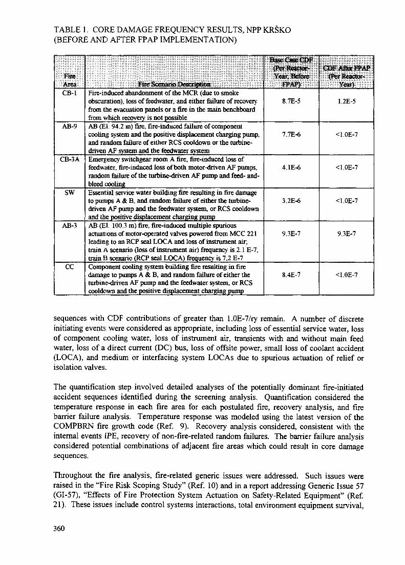
TABLE 1. CORE DAMAGE FREQUENCY RESULTS, NPP KRSKO(BEFORE AND AFTER FPAP IMPLEMENTATION)
FireAreaCB-1
AB-9
CB-3A
SW
AB-3
CC
Fire Scenario DescriptkraFire-induced abandonment of the MCR (due to smokeobscuration), loss of feedwater, and either failure of recoveryfrom the evacuation panels or a fire in the main benchboardfrom which recovery is not possibleAB (El. 94.2 m) fire, fire-induced failure of componentcooling system and the positive displacement charging pump,and random failure of either RCS cooldown or the turbine-driven AF system and the feedwater systemEmergency switchgear room A fire, fire-induced loss offeedwater, fire-induced loss of both motor-driven AF pumps,random failure of the turbine-driven AF pump and feed- and-bleed coolingEssential service water building fire resulting in fire damageto pumps A & B, and random failure of either the turbine-driven AF pump and the feedwater system, or RCS cooldownand the positive displacement charging pumpAB (El. 100.3 m) fire, fire-induced multiple spuriousactuations of motor-operated valves powered from MCC 221leading to an RCP seal LOCA and loss of instrument air;train A scenario (loss of instrument air) frequency is 2.1 E-7,train B scenario (RCP seal LOCA) frequency is 7.2 E-7Component cooling system building fire resulting in firedamage to pumps A & B, and random failure of either theturbine-driven AF pump and the feedwater system, or RCScooldown and the positive displacement charging pump
Base Case CDF(Per Reactor-Year, Before
FPAP)
8.7E-5
7.7E-6
4.1E-6
3.2E-6
9.3E-7
8.4E-7
CDF After FPAP(Per Reactor-
Year}
1.2E-5
<1.0E-7
<1.0E-7
<1.0E-7
9.3E-7
<1.0E-7
sequences with CDF contributions of greater than l.OE-7/ry remain. A number of discreteinitiating events were considered as appropriate, including loss of essential service water, lossof component cooling water, loss of instrument air, transients with and without main feedwater, loss of a direct current (DC) bus, loss of offsite power, small loss of coolant accident(LOCA), and medium or interfacing system LOCAs due to spurious actuation of relief orisolation valves.
The quantification step involved detailed analyses of the potentially dominant fire-initiatedaccident sequences identified during the screening analysis. Quantification considered thetemperature response in each fire area for each postulated fire, recovery analysis, and firebarrier failure analysis. Temperature response was modeled using the latest version of theCOMPBRN fire growth code (Ref. 9). Recovery analysis considered, consistent with theinternal events [PE, recovery of non-fire-related random failures. The barrier failure analysisconsidered potential combinations of adjacent fire areas which could result in core damagesequences.
Throughout the fire analysis, fire-related generic issues were addressed. Such issues wereraised in the "Fire Risk Scoping Study" (Ref. 10) and in a report addressing Generic Issue 57(GI-57), "Effects of Fire Protection System Actuation on Safety-Related Equipment" (Ref.21). These issues include control systems interactions, total environment equipment survival,
360

manual fire brigade effectiveness, inadvertent and advertent fire protection systems (FPSs)actuation, and seismic/fire interactions.
Six fire areas were found to have core damage frequency contributions of greater than 1.0E-7/ry before implementation of modifications. After implementation of FPAP modifications,only two such areas are identified. The pre- and post-implementation CDF results for NPPKrsko are shown in Table 1.
5.0 Level 2 Methods and Results
The fire analysis containment event tree (CET) quantification methodology (Ref. 6) wasconsistent with the internal events IPE containment analysis (Ref. 5). The same bridge trees,containment system success criteria, CETs, and recovery analysis assumptions were used inthe fire Level 2 analysis as in the internal events IPE.
The structure of the Level 1 fire IPEEE did not address containment heat removal (CHR)systems in the CDF quantification. Thus, it was necessary to construct a containment systemtree (CST) or bridge tree to complete the system probabilistic analysis and to define the plantdamage states (PDS) needed to perform source term analyses. The steps used to quantify thePDS are:
1. Quantify the CDF and obtain the dominant contributors2. Construct the CST3. Determine the success criteria for the top events in the CST4. Define the PDS5. Assign (and "bin" together) the dominant core damage sequences into the PDS6. Link the containment systems fault trees to the dominant core melt sequences
and quantify the frequency of each PDS
The PDS is a function of specific plant characteristics important to containment performance.These plant characteristics include the following:
1. Level 1 fire-induced initiating event (small loss of coolant, S, or transient, T)2. Time of core melt (less than or greater than four hours; early, E, or late, L)3. Core melt and reactor pressure vessel (RPV) failure pressure (high, H, or
low, L)4. Status of the emergency core cooling system (ECCS) (injection before reactor
vessel failure, B; injection after reactor vessel failure, A; no injection, N)5. Status of containment heat removal, addressing containment spray injection
(CSI), containment spray recirculation (CSR), and RCFC (containment heatremoval success, Y; containment heat removal failure, N)
6. Status of containment (initially intact, N; containment isolation failed, I)
The CET developed in Reference 22 was used for the fire scenarios. In addition, the sourceterms corresponding to each release category were maintained. Each PDS is processedthrough the CET. At each CET node a probability was developed which describes theconfidence of the analysts that the event will or will not occur for the accident sequence underconsideration. Once the nodal probabilities are developed for a PDS, the CET is quantified bymultiplying the component probabilities and determining the probability of occurrence of
361

TABLE 2. NPP KRSKO FIRE PSA LEVEL 2 RESULTS
ReleaseCategoryNumber
—I2
3A
3B
45A
5B
6
7A788ASB
Release Category DefinitionCoreDajaageFreqaencyCons ftecoveasd in-Vessd; No Containment FailureNo CoataratflejUFailBteLate (Beyond 24 Hams) Coft&innjeat FaUare, >JoJwOlfeifl OO^SHODQGUCfO A2C&GK. ;
BasematFoaetsattQia (l^toCh^iHesaireFaiiare}JEsterste4ia$eCFrostBnd^lU>pidl)^ris-Co(^aittl«teadK»£»-Vasseito24lfe«s6) Cmtam&A Fatoe,No Molten Core-Concrete AttackInteataediate FT<MaEad«fB^pfi<i Debais-CoolaatiBtraaction Ex-Vessel 6> 24 Ho«rs)CoBtaiaiBeHt Faiiarc,
l^rfy TOHt Cfcwef of S gJMficswt ZiiwmiHJTJ OxidationHcanTum Tferit V « S B 4 FsiitHW awl Fad «f ContJtiBrtwm*
DynaraKSfisgxHJSeto VesselFattureorEndof Ra|Hd:fxtd E)ebris/CooiaBt inieractioB Ex-Vessel) ConfaHuaeat
^SQt^^os Fs^^uc^ o ftwOitoft Ocffie C<QdC3filie Attuclc£ $ ^ ^ ^ U ) B i^fj^iyftt jfh c $eQ C^s^e^Qo&cccie Att^^.
Bvpt^, ScrajbbedBypass, Uasciateed
Base CaseRelease
1.0E-4
a2A&43.5E-7
8.1E-5
6.8E-78.5E-6
I.2E-7
I.7E-7
1.2E-69h3B-6
00
Retease FrequeacyAfter FPAP<Ay)
1.2E-50
4.0&«
*7&6
9,7E-7
1.4E^
1JE4
I.2E-7l,2E-$
0
TABLE 3. NE KRSKO FIRE PROTECTION ACTION PLAN COST-BENEFITANALYSIS RESULTS
FiieArea
AB-9
CB-3A
SW
CDF(per
reactor*year)
paael${ffiiniiBallist)Install area swifllder
Install tbree^Ksir c^blc
over f»W tn fflrs, iwstsB
BOttt OiHc wiaps (laiocpower cafeles)
Before FPAP
410
3.S
2.9
U
CostbvNEK
S3^000
$63,000
GDFAfter
reactor-
1.2E-5
<1.0E-7
Perscn^tem
A&a-FI>AP j
^.0
0,0
0* |
362
each release category conditional on the occurrence of the given PDS. The process is repeatedforallPDS.
The Krsko fire PSA release categories are defined in Table 2. The table also shows the resultsof the PDS mapping by providing the frequency of the release category. Frequencies areshown for the "base case" (as-found condition of the plant) as well as for the case which willexist after implementation of the FPAP.
After implementation of the FPAP recommendations the release category frequencies arebeing dominated by the control room abandonment fire scenario. The only other remainingunscreened fire area AB-3 contributes less than eight percent to the total.
Four containment release categories were found to contribute 97.5% to the total CETfrequency before modifications. After implementation of the modifications, three releasecategories contribute the same percentage to the reduced frequency total.
6.0 Level 3 Methods and Results
The MAAP4-DOSE code was used to calculate the consequences of the release categories,using site population and meteorological data. The resulting consequences, in person-rem perreactor-year, were multiplied by twenty to account for 20 years of remaining plant life. Therisk results were calculated before and after implementation of modifications. The 20-yearrisk from fire-induced severe accidents before the modifications was 49 person-rem (0.49person-Sieverts). After implementation of the modifications, the 20-year risk was 6.1 person-rem (0.061 person-Sieverts), a reduction by a factor of more than eight. The Level 3 and cost-benefit results are shown in Table 3.
7.0 Follow-Up Actions
Based on the recommendations in the Fire Protection Action Plan, engineering and designchanges have been initiated and are in progress for the four Category 2 fire areas. Themodification packages include design input/bases, safety evaluations, required FSAR changes,supporting analyses and calculations, design information and drawings, changes to plantprocedures, and installation and test procedures. The general type of modifications involvecircuit isolations, cable fire-wrapping or rerouting, and/or addition of sprinkler systems.
8.0 Conclusions
Using a risk-based methodology, the Fire Protection Action Plan evaluated and prioritized fireprotection program improvements suggested in three independent reviews. The goal of theprioritization was to identify those improvements which provided the greatest risk reductionand assign the highest priority to such improvements.
Some plant fire protection program improvements and plant modifications have already beencompleted. These modifications, in particular the installation of smoke detectors in controlroom cabinets, have already substantially decreased the fire-induced CDF.
Based on the FPAP review and prioritization, the most important remaining modifications tothe plant to reduce overall fire-induced risk are the Category 2 modifications for fire areas
363

CB-1, CB-3A, AB-9, and SW. These modifications are: (a) circuit isolation of vitalequipment located on the evacuation panels and MCCs and the addition of RCS wide-rangetemperature and PORV control at the evacuation panels; (b) providing a three-hour fire wrapfor train B cabling in fire area CB-3A; (c) installation of a sprinkler system and fire wrappingof cables in the AB basement; and (d) installation of a sprinkler system above and heat shieldbetween the SW pumps, and fire wrapping of SW pump power cables. Implementation ofthese modifications will reduce the fire-induced CDF from approximately 1.0E-4 /ry toapproximately 1.2E-5 /ry, which is equivalent to fire-induced CDF values at western nuclearpower plants after implementation of Appendix R criteria. Design change packages toimplement the Category 2 modifications are currently being developed.
REFERENCES
1. "Krsko Nuclear Power Plant - Fire Hazards Analysis - Assessment for Conformance toUSNRC Fire Protection Criteria - Revision 1," Haliburton NUS, December 1991.
2. J. Lambright, "Analysis of Core Damage Frequency Due to Fire at the Krsko NuclearPower Plant," ICISA Report, December 1992.
3. NPP Krsko OS ART Report.4. J. Lambright, et al., "Probabilistic Safety Assessment of Nuclear Power Plant Krsko
Internal Fire Analysis," Lambright-Dukes Technical Associates, June 1996.5. "Individual Plant Examination of Krsko Nuclear Power Plant," Westinghouse Electric
Corporation, August 1995.6. J. Lambright, "Level 2 Internal Fire Analysis of Nuclear Power Plant Krsko,"
Lambright Technical Associates, June 1997.7. "Guidelines for Fire Protection for Nuclear Power Plants," Branch Technical Position
CMEB 9.5-1, United States Nuclear Regulatory Commission.8. "Fire Protection Program for Nuclear Power Facilities Operating Prior to January 1,
1979," United States Code of Federal Regulations, Title 10, Part 50, Appendix R.9. V. Ho and N. Siu, "COMPBRN III - A Computer Code for Modeling Compartment
Fires," UCLA-ENG-8524, University of California at Los Angeles, November 1985.10. J. Lambright, et al., "Fire Risk Scoping Study: Investigation of Nuclear Power Plant
Fire Risk, Including Previously Unaddressed Issues," NUREG/CR-5088, January1989.
11. "Individual Plant Examination of External Events (IPEEE) for Severe AccidentVulnerabilities - 10 CFR §50/54(f)," Generic Letter 88-20, Supplement 4, UnitedStates Nuclear Regulatory Commission, June 28,1991.
12. "Procedural and Submittal Guidance for the Individual Plant Examination of ExternalEvents for Severe Accident Vulnerabilities," NUREG-1407, United States NuclearRegulatory Commission, May 1991.
13. S. Heaberlin, et al., "A Handbook for Value/Impact Assessment," NUREG/CR-3568,December 1983.
14. E. Claiborne, et al., "Generic Cost Estimates," NUREG/CR-4627, February 1989.15. B. Lopez-Vitale, et al., "FORECAST 3.0 User Manual," Science and Engineering
Associates, April 1990.16. M. Bolin and J. Lambright, "Procedures for the External Event Core Damage
Frequency Analyses for NUREG-1150," NUREG/CR-4840, December 1990.17. J. Lambright, et al., "Analysis of the LaSalle Unit 2 Nuclear Power Plant: Risk
Methods Integration and Evaluation Program (RMIEP), Internal Fire Analysis,"NUREG/CR-4832, Vol. 9, March 1993.
364

18. J. Lambright, et al., "Evaluation of Potential Severe Accidents During Low Power andShutdown Operations at Grand Gulf, Unit 1, Analysis of Core Damage Frequencyfrom Internal Fire Events for Plant Operational State 5 During a Refueling Outage,"NUREG/CR-6143, Vol. 3, July 1994.
19. "Reactor Safety Study: An Assessment of Accident Risks in U.S. Nuclear PowerPlants," WASH-1400, United States Nuclear Regulatory Commission, September1975.
20. "Reactor Risk Reference Document," NUREG-1150, United States NuclearRegulatory Commission, Vols. 1-3, February 1987.
21. J. Lambright, et al., "Evaluation of Generic Issue 57: Effects of Fire Protection SystemActuation on Safety-Related Equipment: Root Cause Development and SummaryReport," NUREG/CR-5580, December 1992.
22. "Individual Plant Examination of Krsko Nuclear Power Plant Level 2 Report,"Westinghouse Electric Corporation, August 1995.
NEXT PAGE(S)left BLANK
365

IAEA-SM-345/18
FIRE PROTECTION PROGRAMME DURING CONSTRUCTIONOF THE CHASHMA NUCLEAR POWER PLANT
M. MIAN UMERProject Services Division, XA9847535Chashma Nuclear Plant Project,Pakistan Atomic Energy Commisssion,Kundian, Mianwali,Pakistan
Abstract
A clear view is given of several measures that have been taken with regard to fire prevention,protection and fire fighting during all phases of the construction, installation and commissioning ofthe Chashma nuclear power plant to protect personnel and equipment so that any delays in plantoperation as a result of fire incident can be avoided. These measures include the precautions taken, theprovisions made for fire exstinguishers and hydrants, and the setting up of a fire brigade. An overviewis also given of the fire incidents that have occurred.
While under construction, a Nuclear Power Plant does not differ in any fundamental respectfrom, for example a conventional steam power plant or any other industrial plant of similarsize as regard fire protection systems. Rather a high density of valuable equipment andcomponents is reached during the installation phase. Any delay in start of commercialoperation, justify an above average level of fire protection on the site also during the erectionof the plant.
This paper outline fire protection programme at Chashma Nuclear Power Project site,beginning from start of construction activities through erection and installation.
This include fire protection management and organization, precautions during constructionand erection, provisional fire fighting system, establishing fire brigade, off site assistance infire fighting, over view of fire incidences occurred at site etc.
Fire Protection Management and Organization
At the very outset of the plant construction (early 1992) for example with mobilization of themain contractor, a fire protection organization was formed at the site, with the Deputy GeneralManager (Construction) as overall responsible for the fire prevention programme assisted by a"Fire Protection Manager", a "Fire Officer" and a "Fire Squad". In view of the type ofcontract for the plant, the responsibility of implementation of fire protection at main plantbuildings, preparation areas, workshops, residential areas of expatriates and local contractors,is that of the main contractor.
Organization of Main Contractor
Following the international and national guide lines for the fire protection of nuclear powerplants, fire protection and fire fighting organization was also formed by the main contractorwith the collaboration of sub-contractors. The same is lead / headed by a qualified andexperienced fire manager assisted by the fire officers of sub-contractors.
367

The Fire Protection Manager is a Sr. Officer with sufficient fire protection engineeringexperience and knowledge of radiological protection.
Similarly Fire Officer have sufficient fire prevention, protection and fire fighting experienceand knowledge. While fire squad comprised of trained workers.
The organization has been sub-divided into three level i.e. company, section and team. Eachlevel is responsible for their own work area. At the company level each sub-contractor hasappointed a fire officer and each section in the company have fire fighters responsible for fireprevention and fire fighting in their respective job areas.
Each work team in a section has at least one fire fighter responsible for fire prevention at theirspecific work area.
Responsibilities of the Owner
Chashma Nuclear Power Plant management is responsible for overall management andimplementation of the progrramme, through audit and inspection of contracto's fire protection/ prevention plain and activities.
Joint inspection / audit visits of the site is carried out to ensure the implementation of theprogramme.
The implementation of the programme in office buildings used by CNPP project managementand construction staff is sole responsibility of CNPP.
Owner Fire Brigade Facilities
Chashma Nuclear Power Plant fire brigade with full facilities i.e. two nos. of FIRE TENDER,two AMBULANCE and tranined FIRE FIGHTERS and qualified COMPOUNDERS" isavaiable at site round the clock.
Emergency telephone at the fire brigade post has been well displayed to the all parties at site.
Precautions Taken
The fire protection measures are based upon, devising the preventive measures with the aim of
a) minimizing the fire loadingb) preventing the out break of firec) limiting the spread of fire and localizing the damaged) arranging appropriate fire fighting devices and measures which are brought into action
upon out break of fire.
Accordingly the following precautions have been taken with the advancement of constructionand erection activities:
a) Good House Keeping: The construction site and the workshop areas are kept cleanand orderly, through periodic surveillance and rounds by CNPP fire officer and his
368

counter part of contractors organization. The combustibles used are limited. Thewaste materials are collected and disposed of as soon as possible. The material used inconstruction i.e. form work, scaffolding, decking etc. are made of non-consumable andfire retardent treated wood.
All kind of stores / warehouses housed with combustible are established out side theplant buildings at a safer distance from the plant buildings and also from each other.International codes are followed in storing goods in warehouses.
b) Issuance of Fire Permit: To prevent outbreak of fire special attention is being givento welding and cutting operations. The operation involving use of open flames isproperly supervised. In particular, written prior permission "FIRE PERMIT" is beingissued by fire manager of the contractor, and welding supervisor/firemen ensure thatproper fire protection and prevention measures are taken for the work. A fireman withappropriate type of fire extinguisher is always available for all welding / cuttingoperations which could be dangerous. Such operations are under taken only after allcombustible materials that can be removed has left the area and those which could notbe removed are covered with fire resistance tarpaulin. Thorough inspections of thevicinity and potentially affected zones are made immediately after the termination ofeach work.
c) Patrolling During Off-Hours: Fire and security men frequently patrol the buildingsafter working hours to cope with the possibility of delayed ignition which could bereason for out break of fire.
d) Prevention of Unauthorized Entry: The construction site has been enclosed bybarbed wire, perimeter lighting installed where ever required and the main entrancesare manned to prevent prospective of intruders.
e) Provision of Fire Extinguisher: With the start of construction work, portable fireextinguisher of appropriate type and capacity were provided at all location. Fire groupswith individuals having basic knowledge about type of fire, use of fire extinguishersand action to be initiated on out-break of fire were set up.
f) Enhancement of Facilities: The number and places of appliances are increased instep with the progress of work at site.A provisional system of fire hydrants was made available well before installation ofplant equipment and components in the main buildings i.e. N.I. and C.I. The systemconsisted of a main ground level water tank, two auxiliary ground level tanks,pressurized fire water main, fire hydrants / stand pipes and hose reels at "appropriatelocation on all levels of the buildings". Besides, hydrants with hose reels are alsoprovided outside around the main plant buildings, the warehouse, auxiliary boilerhouse etc.
g) Traing of Fire Crew and Plant Personnel: With the collaboration of local CivilDefense Authority and National Institute of Fire Technology, Islmabad, class trainingis conducted for fire fighters, security men and operation and maintenance personnelsbesides class and field training conducted by senior colleagues.
One site fire drills (dry and wet) are regularly held to cope with any fire incidentefficiently and effectively.
369

Over View of Fire Incidences Occurred at Site
Since start of construction activities about twelve insignificant fire incidents of small fireshave been occurred in different places due to various reasons.
The incidents occurred in main plant buildings attributed to waste material such as jute bags,wooden scrap, packing material, welding and unauthorized use of electric heater. No loss togoods, building, equipment or human was occurred, due to the deployment of effective firefighting facilities. The incidences occurred out side in open areas was due to shrubs and drygrass etc.
Experience gained from these fire incidents is that, more attention was given to housekeeping, vigilant patrolling inside the plant buildings to notice the waste material and toremove the same on priority basis. Welding and cutting operation are carried out under strictsupervisions. Unauthorized use of making fire and smoking in the construction premises isstrictly banned and penalty upto US $ 500 has been fixed with the termination from job fordefaulters.
Wild growth and shrubs are cleared regularly all around the plant buildings. Patrolling of thesite round the clock by firemen and security personnel intensified. Nos. of fire extinguishersincreased. Plant fire brigade is kept on alert round the clock.
As a result of these improvement the frequency of occurrence of fire incidents is reducedconsiderably.
370

IAEA-SM-345/23
OPTIMIZATION OF EXTINGUISHING AGENTSFOR NUCLEAR POWER PLANTS
illiniumM. BOLEMAN, M. LIPAR XA9847536Nuclear Power Plant Bohunice,Jaslovske Bohunice
K. BALOGFire-technical and Expertise Institute
of Ministry of Interior,Bratislava
Slovakia
Abstract
Focus is placed on use of extinguishing agents in nuclear power plants. The advantages anddisadvantages of these agents are compared. Further perspectives for using particular extinguishingagents in nuclear power plants are outlined.
Introduction
Fire protection is an indivisible part of power plant's nuclear safety. A fire in the plantcan cause big material damage, electrical power production failure, but it may also cause anaccident and radioactive leakage to the atmosphere. This is why a maximum care for the fireprotection from designing to decomissioning of a power plant is so neccessary.
In my talk, I would like to focus profoundly on the last phase of fire protection -extinguisthing.
Talking abour particular extinguishing agents I will focus on their present use at PWRNPPs, their perspectives and disadvantages of their use.
Water
It is the extinguishing agent used the most often in power plants. It is used in outer unittransformer fixed extinguishing devices in the form of water fog and in fixed extinguishingequipments protecting cable areas and Diessel-generator stations.
Water can also be used in the form of a water stop as an agent dividing fire-dangerousplaces where other forms of division are technically impossible or too expensive.
Water is available at all the buildings of a nuclear power plant through the waterdistribution systems and through underground and overhead hydrants.
Water can be used for voltage electrical equipment extinguishing. No devices andextinguishing equipmet have been designed for larger voltage electrical equipment fires.
371
Devices important for safety reactor shut-out and residual heat withdrawal cannot be turnedoff nor in the case of fire. In the EGU Bechovice, there has been an experimet carried outproving that voltage electrical equipment can be extinguished by water in case of keepingcertain technical conditions and space-gaps. Based on this experiment, the SlovakStandardization Authority allowed some Slovak Technical Standards exeptions for voltageelectrical equipment extinguishing in Slovak NPPs .
Perspectives
Water will be the most often used extinguishing agent at NPPs, henceforth. It is alsopossible to upgrade its extinguishing effect by adding modern foam creating concentrates andwetting agents (AFFF, Pyrocool).
Usage of new forms of extinguishing Micro drop, Infex.
Disadvantages
Arising of contaminated water in the primary circuit and thus rising amount ofradioactive waste. Water extinguishing and using boric acid at the same time brings thedanger of boric acid dilution.
Foam
Foam is used mainly for inflammable liquids extinguishing at nuclear power plantsand in older projects also for cable areas fixed extinguishing equipment. Highly expansivefoam from mobile foam agregates is advantageous for being used for filling cable areas up incase of fixed extinguishing equipment failure or in case of fire in oulet cable areas which arenot equiped by fixed extinguishing equipment. Nowadays, foam is also proposed to be theextinguishing agent for protective fixed extinguishing equipment for Diessel-generatorstations (Siemens). Foam is unreplaceable in case of outer transformers fixed extinguishingequipment failure. Foam fixed extinguishing equipment is also advantageuos for main turbo-generator oil tanks and oil feeding pump systems protection.
Physical, chemical and extinguishing features of foamers used in nuclear power plantshas been analysed. It is necessary to pay higher attention to choosing foam creatingconcentrates for risky places focusing on their service life, effectiveness and theirneutralization after the service life elapse.
Perspectives
For its great inflammable materials extinguishing qualities and since there is a lot ofsuch materials in a nuclear power plant, mobile equipment and also fixed extinguishingequipment foam wil be mainly used in future.
Disadvantages
Rising of radioactive waste amount in the primary circuit. Necessity to replace thefoamer after its guaranatee term.
372
Extinguishing powders
Experience has showed it is not suitable to install powder fixed extinguishingequipment in power plants. The use of powder is concentrated into extinguishers. It is alsouseful to have some powder supplies in a fire-extinguishing tanker mainly for imflammablematerials, cable areas and voltage electrical devices extinguishing.
Perspectives
Powders are supposed to be used broadly in nuclear power engergetics in case of fastneutron reactors with a liquid sodium cooler.
Disadvantages
Invalidation of extinguished electronic devices and rising of a radioactive wasteamount in the controlled zone.
Carbon dioxide
Carbon dioxide is used mainly in extinguishers for electric voltage devices. After theuse of halogens had been reduced the importance of carbon dioxide rised also for fixedextinguishing equipment for example oil systems (NPP Temelin) and for main circulatingpump deck extinguishing projects (Siemens).
Perspectives
Henceforth, carbon dioxide will be used mainly in extinguishers. It may be used as apossible replacement of halogens in fixed extinguishing equipment.
Disadvantages
Comparing to other alternatives, there is a higher extinguishing concentrationnecessary which is of fatal danger for the service personnel. Extinguishing agents contributingto strenghtening the greenhouse effect (GWP) are being reassessed nowadays.
Halogens
Halogens are extinguishing agents very suitable for nuclear power plants. Their usageis limited by the 1987 Montreal Protocol. It is a nearly unreplaceable extinguishing agent innuclear plant conditions. They are used for voltage electrical devices, electronic devices andimportant cable areas extinguishing.
Model experimets with halogens and halogen alternatives should verify theeffectiveness of closed room flame extinguishing and their ability to prevent reflaming of
373

infalmmable materials. These experiments are being proposed since the information onextinguishing abilities of halogen hydrocarbons available till now are tested by Cup BurnerTest. According to the search of literature, room extinguishing concentrations are designedwith 20% reserve. Since from the point of view of chemical mechanism the alternative agentseffects are lower than the halogen ones, the experiment should verify the extinguishingagent's ability of volume extinguishing. There is to be halogen 1031 compared with halogenalternatives (CAE-410, FM 200, Halotron II) within the experimet.
Perspectives
The use of halogens at nuclear power plants was not openly prohibited in Slovakia.Halogen 1301, used mostly in fixed extinguishing equipment, is not available at the market.Considering demanded extinguishing abilities, non rising of a radioactive waste amount andnon invalidation of extinguished devices, halogens are still a very perspective extinguishingagent in Slovakia.
Disadvantages
Damage of the ozon layer (ODP), contibution to the greenhouse effect (GWP) andproportionally long term of life in the atmosphere (AL).
Conclusion
In conclusion, it can be claimed that there are all kinds of extinguishing agents usedwithin modern fire protection in conditions of nuclear power plants. We have to undertakeseveral aspects using extinguishing agents for manual extinguishing, fixed extinguishingequipment and fire-extinguishing tankers. The extinguishing agent has to have goodextinguishing effects, must not divaluate the extinguished material, must not support furtherrise of contaminated waste amount and must not have an environmental impact.
Having undertaken all these aspects we have to choose the most suitable extinguishingequipment for the particular area of the plant.
BIBLIOGRAPHY
Safety guide No. 50-SG-D2 (rev.l.), Fire Protection in Nuclear Power Plants, International AtomicEnergy Agency, Vienna, 1992
Safety Practices No. 50-P-9, Evaluation of Fire Hazard Analyses for Nuclear Power Plants
Orlikova, K.: Chemie hasebnich latek (Extinguishing Materials Chemistry) Ucebni texty VSB,Ostrava, 1995
Orlikova, K. - Zapletalova, I.: Chemie haseni a procesy haseni (Extinguishing Chemistry andProcesses) Ucebni texty VSB, Ostrava, 1991
Probabilistic Safety Assessment forNPP V-l, Level 1, Fire Analyses Task 8, Electro Watt WeringtonEngland, 1944
374

Skvarka, P.: Poziarna bezpecnosf JE V-l (Cast' novelizovanej bezpecnostnej spravy) (NPP V-lNuclear Safety. A Part of the Ammended Safety Report) VS VUPEK c. 890-40-17-9 Bratislava,June 1990
Zaverecna sprava z riesenia DU 09 ,,Poziarna bezpecnost' JE", VS (Closing Report from a 09Partial Task Solution "NPP Fire Safety". Research Report) Relko c. 1R 1193, Bratislava,November 1993
Orlikova, K.: Hasebni latky (Extinguishing agents) Sdruzeni pozamiho a bezpecnostniho inzenyrstvi,Ostrava, 1995
375

CLOSING SESSION
Chairperson
M.J. KULIGIAEA

IAEA-SM-345/46
CURRENT AND FUTURE IAEA ACTIVITIESm THE AREA OF F,RE SAFETY ^ g ^
M.J. KULIG XA9847537Division of Nuclear Installation Safety,International Atomic Energy AgencyVienna
Abstract
The paper provides a brief overview of the IAEA programme on fire safety carried out in theperiod 1993-97. The main results of past activities are highlighted with appropriate references to IAEApublications and other papers presented at this Symposium. Ongoing work is presented in more details.This presentation addresses two IAEA documents on the use of fire safety related operational experiencein fire safety assessment currently in preparation. The first document describes potential applications,related data requirements, current reporting practice and the use of experience based data in plant specificanalyses. The second document presents the root cause analysis tailored toward its application to theinvestigation of fires. The paper describes the main objectives, intended scope and contents of these twodocuments and status of document development tasks. Some insights obtained so far are outlined.Another ongoing task addressed in the paper is the development of a list of generic technical safety issueswhich limit the current capabilities of fire safety assessment. The paper describes the approach proposedby the IAEA in the compilation of a list that would represent broader international views. Finally, thepaper addresses the future IAEA activities in the area of fire safety. These concentrate on the completionof ongoing work on guidelines and good practice documents, exchange of technical information in thearea of fire safety at nuclear facilities, and fire safety review missions and training.
1. INTRODUCTION
The IAEA initiated a comprehensive programme on fire safety at nuclear power plantsin 1993. The first project conducted within the framework of this programme devoted to "FireSafety" was successfully carried out by the end of 1996. As of the beginning of 1997 the firesafety related activities were included in two new projects, one on "Current Engineering SafetyIssues" and the other on "Engineering Safety Advisory Services".
The IAEA programme is intended to provide assistance to Member States in improvingfire safety in nuclear power plants. In order to achieve this general objective, the IAEAprogramme aims at the development of guidelines and good practices, the promotion of advancedfire safety techniques, the exchange of state of the art information between practitioners and theprovision of engineering safety advisory services and training in the implementation ofinternationally accepted practices.
2. OVERVIEW OF THE PROGRAMME AND ITS RESULTS
2.1. Development of guidelines and good practices
During the period 1993-94, the IAEA programme concentrated on fire safety and fireprotection of operating plants with the main focus on the development of guidelines and goodpractice documents. One of the first tasks was the development of a Safety Guide [1] thatformulates specific requirements with regard to fire safety of operating nuclear power plants.Draft document prepared in 1995 is being in the review for final acceptance of Member States.
379

A more detailed information on this document is provided in the paper entitled "Overview ofIAEA published guidelines for fire safety inspection and operation in NPPs" (No. 28) presentedat this Symposium.
Several good practice documents [2-4], which provide advice on fire safety inspection,were developed to assist in the implementation of this Safety Guide. These documents havealready been published in IAEA NUSS Series as Safety Practices. These publications address altechnical aspects of fire safety inspection at NPPs including fire protection measures and firefighting capability[2], fire protection system organization, management and procedural control[3], and evaluation of fire hazard analysis [4]. A more detailed information on this document isprovided in the paper No. 28 presented at this Symposium.
In 1995-96 the programme concentrated on the development of good practices in thepreparation of fire safety analysis. Two documents providing advice on the preparation ofsystematic fire safety analysis at NPPs have been developed and are being prepared forpublication in Safety Reports Series: "Preparation of Fire Hazard Analyses for Nuclear PowerPlants" [5] and "Treatment of Internal Fires in Probabilistic Safety Assessment of Nuclear PowerPlants" [6].
The first report is intended to facilitate the preparation of a deterministic analysis of firehazard. The second report describes in detail good practices in the preparation of probabilisticsafety assessment for fires at NPPs. It is intended to facilitate the implementation of a risk basedapproach in fire safety assessment for NPPs based on current practical experience gained in thisarea. A more detailed information on these two documents is provided in the paper No. 28.
In 1997 new tasks were initiated in the area of practical application of fire safety relatedoperational experience at NPPs. Two good practice documents devoted to the collection and useof operational experience are under development: one on the collection and use of fire safetyrelated operational experience and another on root cause analysis of fire safety related events.A more detailed description of these ongoing tasks will be provided in this paper. Developmentof another IAEA document addressing lessons learned from fire events is planned for the period1998/99.
2.2. Exchange of information
Exchange of information on fire safety and fire protection at NPPs werecontinuing activities. Technical Committee Meetings have been organized regularly every yearin order to review draft documents, to obtain advice on the direction and scope of future projectactivities and to reach international consensus on selected fire safety related topics. In addition,these meetings provided a forum for the exchange of up-to-date information betweenpractitioners on fire safety related issues.
This Symposium is one of the relevant events that facilitate the exchange of technicalinformation. It focuses on effective methods, practices and criteria applied in the fire safetyassessment and upgrading of nuclear power plants.
One of the tasks that serve the purpose of information exchange in the area of fire safetyassessment is the development of a list of fire safety related technical issues. The utility of a listwhich represents broader international views and the potential role the IAEA may play in its
380

compilation provide a good motivation to make an effort in this direction. This activity will bediscussed in more details in this paper.
2.3. Fire safety reviews and training
Assistance is provided in the systematic assessment of fire safety of nuclear power plantsin Member States. The organization of fire safety review missions and training courses on firesafety and fire protection are continuing activities.
Six fire safety review missions were conducted in the period 1993-1997 to evaluate theadequacy of fire safety in selected nuclear power plants. These plants were in different stages ofconstruction and operation and the scope and depth of the evaluation varied. Some practicalinsights from these fire safety review missions are discussed in the paper entitled "IAEA firesafety review missions to NPPs" (No. 29).
An IAEA document [7] providing guidance for the experts involved in the organizationand conduct of fire safety review missions has been completed and approved for publication inIAEA-TEC-DOC Series. A more detailed information on this document is provided in the paperNo. 28 presented at this Symposium.
Interregional training courses were typical training activities organized by the IAEAin the area of fire safety. Two interregional training courses on "Fire Protection andEnvironmental Qualification of Equipment Important to Safety in Nuclear Power Plants" wereorganized - one in Mumbay (formerly Bombay), India (in 1995), and the other dividedbetween Argonne, USA and Toronto, Canada (in 1996). Several specific training missions orworkshops initiated at the request of a Member States have been provided within theframework of Technical Assistance and Co-operation programmes.
3. ONGOING WORK
Current activities in the area of fire safety of nuclear power plants focused on the useof fire related operational experience. There are two IAEA-TEC-DOCs under preparationdevoted to this subject: "Use of Operating Experience in Fire Safety Assessment of NuclearPower Plants" and "Root Cause Analysis of Fire Safety Related Events at Nuclear PowerPlants". The main objectives, intended scope and contents of these documents as well as themain insights obtained so far are presented below.
3.1. Use of operational experience in fire safety assessment of nuclear power plants
The objective of this TEC-DOC is to provide good practice information on thecollection and use of fire safety related operational experience. The publication is intendedto assist plant/utility staff responsible for collecting plant raw data related to fire safety andthe analysts involved in fire safety assessment of NPPs.
The material presented in the document may help to make informed decisions relatedto data reporting systems by the utilities/plants. It is essential that a rational compromisebetween 'analyst's wishes' and data collector's ability and willingness to provide required inputis reached. The document is intended to address the subject taking this aspect intoconsideration.
381

The document will describe potential applications of operational experience in theassessment of fire safety for NPPs. Desirable scope of data reporting to satisfy the needsspecific to various applications and to various aspects of fire safety assessment will bediscussed with special consideration given to the needs of risk based fire safety assessment.The availability and accessibility of information in the existing data reporting practice willbe addressed and some practical examples of data reporting systems will be given. Thedocument will also provide some advice on how to use the available nuclear industry data,often imperfect or incomplete, in order to generate acceptable plant specific data.
The preparation of the document is well advanced. However, the existing draft is notcomplete and has to be extended to cover additional topics mainly related to the applicationof the existing experience based data. Work on this document is planned to be continued in1997/98. Some insights from this study regarding the potential applications, related datarequirements, current reporting practice and the use of industry data in plant specific analysesare summarized below.
Direct use of operational experience such as root cause analysis or trend analysis isthe most straightforward application. These methods are powerful tools capable to identifyfire protection deficiencies in safety culture area which could be hardly identified by plantinspection or by quantitative hazard analysis. Direct methods, in particular the root causeanalysis, are most effective when conducted at the plant level with strong involvement ofplant personnel.
Indirect use of historical plant data is of prime interest to any quantitative fire safetyanalysis. The main data derived from plant operational experience include fire eventfrequencies, fire detection and suppression times, probability of fire growth as well as failurerates for human actions and for fire protection equipment.
Use of historical operational data in a qualitative way in order to support a plantspecific modelling of physical fire phenomena is another important application. However,there are some practical limitations as the existing fire event reporting systems are notsufficiently detailed to allow for suitable extrapolation to the conditions specific to plant, plantfire compartment and/or the threat being considered in a plant specific analysis.
Direct in-depth analyses such as root cause analysis or trend analysis requireinformation on broad range of events including those that do not have safety significance butare relevant to safety (deviations). The level of detail of information required for theseapplications (e.g. for identification of root causes) is relatively high. The information scopeis usually beyond the scope of a typical fire event reporting system. Information sources mayinclude a large variety of plant operational records (e.g. station log, plant control log,workshop logs, maintenance records), special investigation reports, manufacturing/erectionrecords and interviews with plant personnel involved.
Indirect application of operational experience relay mainly on fire event data. Fireevent frequencies, fire detection and suppression times, probabilities of fire growth and failurerates for human actions are estimated using historical fire event information. For reliabilityrates of fire protection equipment this source of data is not sufficient. Information on theresults of surveillance checks, periodic tests and maintenance activities is essential for thisapplication.
382
The availability and quality of data derived from plant operating experience arerecognized unsatisfactory. In some Member States fire safety related events are not reportedin systematic and consistent manner. Often the criteria, scope and format of data reportingneed improvement. The currently available sources of data have not been properly maintainedand are often out of date.
Typical fire event reporting systems have been designed to assist in direct applicationsof data (root cause analysis, trend analysis, regulatory supervision, etc.). They include mainlysafety significant events or events involving significant property loss. Fires of low severityor precursor events are not reported.
In many cases the definition of criteria and format used in data reporting systems arenot precise and involve subjective judgment. That negatively affects the reliability ofinformation provided and the understanding of fire event reports and in consequence theirusefulness.
Considering the limited availability of statistical plant data on fire events as well asother data for estimating the reliability and performance of fire protection equipment andsystems, use of the available worldwide data would be desirable. However, due to the lackof standardized criteria and format, a broader exchange of data at international level andsometimes even at national level is difficult.
The information provided in the existing fire event reporting systems is in many casesunsatisfactory to fulfill the actual needs of fire risk assessment. Information on event time linerequired for estimating the fire detection and suppression times is limited. In certain cases theperformance of the fire detection and fire suppression systems is also difficult to be assessedcorrectly due to the lack of sufficient information provided for the event. Typically, the scopeand level of detail of information provided do not allow for implementing more refined eventpartitioning techniques to estimate the occurrence frequency of a given fire in a given plantlocation (e.g. due to the lack of information on the relevant attributes of the related firecompartment).
Enhancement of the current reporting process would be essential aid to future effortsto learn from past fire events. A more precise definition of reporting criteria, scope andformat is essential to facilitate exchange of data at national and international level. It isdesirable to broaden the scope of data reporting by including events of lower severity and byadding new types of information to be provided for each event. Certain detailed data may bemade available in a plant level system and appropriate cross reference provided in the higherlevel system. For instance, detailed attributes of the related fire compartment (e.g. thepresence of ignition sources, fire load and its distribution, detection system and extinguishingequipment) can be treated in this way.
Extrapolating experience data from plants with different level of fire protectiondefenses is subject to debate and disagreement. One of the important applications in whicha broader use of historical data would be desirable is estimating the occurrence frequency ofa given fire in a given plant location (fire event partitioning). There is no clear consensusregarding the best approach to fire event partitioning. Fire occurrence models used in thepartitioning process are often simplistic and do not take into account all relevant attributes ofthe fire location. Implementation of more sophisticated approaches is limited by the practicalavailability of the related plant specific information in the databases.
383
3.2. Root cause analysis for fire safety related events
The objective of this TEC-DOC is to promulgate the use of the ASSET root causeanalysis methodology for application to the analysis of events involving fire. The documentis intended to be used by fire safety assessors focussing on the direct use by the plant staffinvolved in fire protection. Development of this document is well advanced (a first draft hasbeen prepared).
The document presents the ASSET root cause analysis tailored towards its applicationto the investigation of fires. The methodology is described and illustrated through referenceto a fictitious example. The methodology has been applied to three events in which fires wereinvolved. These events are based on real operational experience of three reference plants. Thedocument illustrates both the practical application of the methodology and the nature of therecommendations which arise. Conclusions from these three analyses are presentedhighlighting the general weaknesses observed.
The three referenced events analyzed had been investigated on the plants without usingroot cause analysis. The application of the ASSET root cause analysis methodology hasextended the insights into the causes of the incidents.
Weaknesses in the field of quality control, surveillance programmes and safety culturewere identified in each case and the importance of these weaknesses was shown. In each ofthe three causes, the event (and all its consequential costs) would have been avoided if onlyappropriate attention had been paid to these "software issues". It remains only to be said thatin general the corrective action in these areas are less costly then the corrective actioninvolving equipment and can usually be put in place in a shorter space of time.
It follows that if the ASSET RCA methodology is used on a routine basis to analyzedeviations, including minor deviations, weaknesses in the field of quality control, surveillanceand safety culture will be identified in a timely manner and if attended to will significantlyreduce the incidence of major events.
3.3. Generic fire related safety issues
One of the tasks carried out at the IAEA in the area of fire risk analysis is compilinga list of technical issues which limit the current capabilities of fire safety analysis. There arecurrently efforts underway over the world to overcome the existing shortcomings andlimitations in fire safety assessment. Co-ordination of activities carried out in this area indifferent Member States is very desirable and a wider listing of the needs would be a strongstep in this direction.
The acceptance by a wide selection of experts will be critical to the credibility of sucha list. Therefore, the proposed approach is tailored to solicit a broader opinion.
A provisional list of issues is planned to be prepared at the IAEA. This list will bedeveloped in co-operation with the selected organizations and/or individual experts who havesufficient experience and knowledge in the subject. Information gathered during theimplementation of IAEA programme will also be used.
384

The provisional list when compiled will be sent to recognised organizations/expertsto obtain their opinion. In this step the recipients will be asked to provide answers to thefollowing questions:
'Is the list complete (if not, what should be added) ?''What issues are applicable (not applicable) to your organization ?''What work is underway or planned in this area in your organization ?''What are the priorities in resolving each of the identified issues ?'
• 'What items are of common interest ?''What form of collaboration could be proposed in resolving each of the identifiedissues ?'
• 'Do you know any other organizations or individuals that might be interested tocontribute to this list ? If so, please forward the list to them for their response.'
In the second iteration some new items may be added to the list and the updated listwould be distributed, basically with the same questions.
The development of a provisional list of technical issues is well advanced. Identifiedissues are grouped into 5 broader categories:
Experience based dataExperimental dataModelling of fire behaviour and effects phenomenaModelling of fire protection systemsOther issues related to risk assessment.
The identified issues cover the needs of both deterministic fire hazard analysis andrisk based assessment. Each issue is identified by a number, and a short title. A more detaileddescription is provided to clarify each issue.
Support and valuable assistance in the development of the provisional list of issues andthe compilation of a distribution list has been given by Mr. C.B. Ramsey1 (U.S. DOE), Mr.S.P. Nowlen (Sandia National Laboratories) and Dr. M. Rowekamp (GRS). Sandia Report"Improvement Need Areas for Fire Risk Analysis" [8] has been a very helpful inspiration forthe development of this list.
4. FUTURE ACTIVITIES
4.1. Guidelines and good practices
Ongoing work on the preparation of good practice documents related to the use of firesafety related operational experience and to the root cause analysis of fire safety relatedevents (initiated in 1997) will be continued. Preparation of a new document highlighting thelessons learned from fire incidents in NPPs is planned to be started in 1998. This documentis intended to compile and summarize the existing studies on the assessment of fire relatedoperational events.
Also an initiator of this undertaking
385

A second revision of Safety Guide "Fire Protection in Nuclear Power Plants" [9] isplanned for the period 1999-2000 as part of the revision of a number of Guides in the NUSSDesign Series. The revision is intended to update the contents of the Guide taking intoaccount progress that have been made in the last decade in design and regulatoryrequirements, in fire protection technology and in related analytical techniques.
The revised Guide is expected to address certain technical issues not covered by theexisting Guide such as the recommended extent of fire safety analysis and the role of fire riskassessment in design and licensing as well as its relation to deterministic fire hazard analysis.Another issue of interest is the practical application of the single failure principle to fireprotection equipment. Interpretation of this principle in the analysis of fire accident sequencesremains controversial and is subject of criticism. The revised Guide is expected to providea more clear guidance on the application of this principle in the deterministic fire hazardanalysis.
4.2. Exchange of information
Technical Committee Meetings are planned to be organized regularly in order toreview draft documents and to obtain advice on the direction and scope of future projectactivities. The next TCM is planned to be held in 1998.
4.3. Fire safety reviews and training
A set of IAEA guidelines and good practice documents covering a broad range ofdesign and operational aspects related to fire safety is nearly complete. Therefore, in the nearfuture the IAEA programme on fire safety will focus on the promotion of practical applicationof the available guidance. This goal will be achieved by providing to Member States safetyadvisory services that includes fire safety review missions and training missions.
The fire safety missions will focus on solving plant specific problems. The scope offire safety missions will be tailored to meet the particular requirements of the plant, takinginto account the specific problems, conditions and needs of each NPP. These services willalso assist in building up the national self-assessment expertise.
Training courses of regional and interregional type are planned to be organized in thearea of fire safety regularly. Typical courses on "Fire Protection and EnvironmentalQualification of Equipment Important to Safety in NPPs" organized by the IAEA in the pastare planned to be modified by separating the subjects of fire safety and the equipmentqualification. The next training course devoted to fire safety and fire protection in nuclearpower plants is planned to be organized in Moscow in 2000.
REFERENCES
[1] INTERNATIONAL ATOMIC ENERGY AGENCY, Fire Safety During Operationof Nuclear Power Plants (to be published in IAEA Safety Series).
[2] INTERNATIONAL ATOMIC ENERGY AGENCY, Inspection of Fire ProtectionMeasures and Fire Fighting Capability at Nuclear Power Plants, IAEA SafetySeries No. 50-P-6, Vienna (1995).
[3] INTERNATIONAL ATOMIC ENERGY AGENCY, Assessment of the OverallFire Safety Arrangements of Nuclear Power Plants, IAEA Safety Series No. 50-P-11, Vienna (1996).
386
[4] INTERNATIONAL ATOMIC ENERGY AGENCY, Evaluation of Fire HazardAnalysis for Nuclear Power Plants, IAEA Safety Series No. 50-P-9, Vienna(1995).
[5] INTERNATIONAL ATOMIC ENERGY AGENCY, Preparation of Fire HazardAnalyses for Nuclear Power Plants (to be published in IAEA Safety Report Series).
[6] INTERNATIONAL ATOMIC ENERGY AGENCY, Treatment of Internal Fires inProbabilistic Safety Assessment for Nuclear Power Plants (to be published inIAEA Safety Report Series).
[7] INTERNATIONAL ATOMIC ENERGY AGENCY, Organization and Conduct ofFire Safety Reviews at Nuclear Power Plants (to be published in IAEA-TEC-DOCSeries).
[8] NOWLEN, S.P., MITCHEL, D.B., TANAKA, T., Improvement Need Areas forFire Risk Analysis, Final Letter Report, Sandia National Laboratories,Albuquerque, New Mexico (1996).
[9] INTERNATIONAL ATOMIC ENERGY AGENCY, Fire Protection in NuclearPower Plants, IAEA Safety Series No.50-SG-D2 (Rev. 1) (1992).
387

CONCLUDING STATEMENT XA9847538
G.W. JONESHealth & Safety Executive,
HM Nuclear Installations InspectorateBootle, Merseyside,
United Kingdom
1. INTRODUCTION
The title of the Symposium, "Upgrading The Fire Safety of Operating Nuclear PowerPlants" reflects the delegates desire and commitment to continually improve the safety oftheir Nuclear Power Plants.
Public acceptance of nuclear power is based on the perception that the radiological riskspresented by Nuclear Power Plants is small and well managed. However even minor fireswith no nuclear safety significance affect this perception and could ultimately threaten theexistence of nuclear power programs. Whilst the Symposium has concentrated on theupgrading of Nuclear Power Plants to mitigate the consequences of fires, everyone hasrecognised the importance of fire prevention.
The papers presented at the Symposium have covered a broad range of topics relating tofire protection and its role in maintaining nuclear safety and have provided acomprehensive view of world-wide developments and practices in analysing fire safety onNuclear Power Plants, and a simple summary of individual sessions would be insufficientto highlight some of the significant issues which arose.
In concluding the Symposium I have attempted to identify those issues which, from thepresentations and discussions, have appeared to be important to the overall achievement ofmaintaining, and most importantly, improving nuclear safety. Therefore I haveconcentrated on four topics; Data, Fire PSA, Fire Safety Reviews and the proposedintroduction of Performance Based Regulation.
2. DATA
It was recognised that accurate and reliable data provides the basis of both deterministic orprobabilistic analyses. A number of data collection initiatives have been described. Themotivation behind these initiatives is the need to support the expanding use of Fire PSAand to develop the use of risk-informed, performance based regulation.Many requirements were discussed, but two have featured prominently, these were the fireinitiation frequency and data relating to the reliability and unavailability of both activeand passive fire protection systems. The value of data in both areas suffered from thegeneric problems of inconsistent reporting, incomplete information and the use ofdifferent reporting standards.
Several database and data collection initiatives have been highlighted including thosefrom WANO, IPSN, India and the NEIL initiative. Whilst these initiatives had the
389
common goal of identifying and recording fire incidents, it was recognised that each wasdifferent, adopting different reporting criteria and recording different types of fireinformation. This is not a criticism of the databases as each was set up for a specificpurpose, but it has made any comparison or unification of the data difficult.
It has been proposed that fire frequency deficiencies can be overcome by expanding theplant data to include generic data from other countries such as the United States, but it isrecognised that the origins of the data needed to be understood and compared against theplant specific conditions before its use. However, this approach may not be appropriate forthe data relating to the reliability and unavailability of fire protection systems, wheredifferences in manufacturing, testing, inspection and maintenance standards aresignificant. It was concluded that this problem could be addressed if each Nuclear PowerPlant were to compile its own plant specific data. The development of the IAEA's TEC-DOC on the "Use of Operating Experience in Fire Safety Assessment of Nuclear PowerPlants" should prove useful in this task.
No matter which source of data is used in analysis, its use is conditional on maintainingthe operational practices and standards applicable to the source of data or at least adoptingpractices that ;ire judged to achieve an equivalent standard. Failure to do this mayinvalidate its use.
There would appear to be a need for international collaboration to improve the dataavailable for fire hazard analysis and this was reflected in delegates request for aninternationally accepted fire classification, incorporated into either the IAEA's INES orIRS.
3. FIRE PSA
The considerable interest in Fire PSA is reflected in the number of papers presented.Significant advances have been made over the years in the application of probabilisticassessment to fires, and many of these advances have recently been recorded in theIAEA's Safety Report on Fire PSA.
It was reported that Fire PSA has been used to supplement the deterministic fire hazardsanalysis and that it is recognised as a tool that has the potential to provide valuableinsights with respect to weaknesses in the plant design and operation. It allows theidentification of dominant risk contributors, the comparison of options for risk reductionand provides a basis for cost benefit analysis.
Ideally the results of the Fire PSA should enable the fire safety engineer to focus onupgrading those aspects of fire safety which contribute to the greatest risk reduction. Theresults of the Fire PSA may also indicate where it is not reasonably practicable to improvesafety further.
However, some delegates drew attention to current limitations on the use of Fire PSA.These included, incompleteness of data, inadequately conceived modelling or mistakes inthe screening out of low frequency events. These could produce fictitious results whichmay obscure the true fire risks, and create a false sense of security. Therefore theapplication of the method needed care and detailed knowledge of the fire phenomena and
390

its potential impact on nuclear safety systems. Moreover the scarcity of appropriate dataintroduces further uncertainty into the results. A number of initiatives are now takingplace throughout the world to address these limitations and uncertainties and it is expectedthat these will feature prominently in the IAEA list of technical issues.
The message appeared to be that the Fire PSA methodology should provide valuableinsights into risk contributors but should be used with caution. Because the results of FirePSA are not testable and are dependent on the analysts knowledge, they should beregarded as input to a decision making process, and judgements on the adequacy of safetylevels should also be dependent on compliance with engineering and deterministic safetystandards.
In the future, as the Utopia of a Fire PSA with no uncertainties is approached, it wasanticipated that the technique could be used to refine the deterministic rules to reduceunnecessary levels of conservatism. In the meantime, the use of Fire PSA should notundermine the defence-in-depth strategy or the deterministic engineering approaches thatare presently the foundation of regulatory decisions. It should be used in combination withthe deterministic methods in a constructive way to identify further cost effectiveimprovements.
4. FIRE SAFETY REVIEWS
The radiological effects of major accidents at nuclear power plants do not respectinternational borders, and operators of Nuclear Power Plant wherever they are in the worldrecognise that the risks associated with their Nuclear Power Plants must be adequatelymanaged. It was recognised that it is important to ensure that the management systemsand hardware systems, put in place to achieve an adequate level of nuclear safety, arethemselves adequately maintained throughout the plants operation.
One of the most effective means of achieving this objective is through periodic fire safetyreviews. Some licensing regimes, recognising its importance, require periodic safetyreviews and plant and equipment upgrades as technology and knowledge advances and socontinually drive risks down. Several examples of the advantages and benefits ofindependent peer reviews have been presented. Independent peer reviews have beencarried out by organisations such as WANO and the IAEA. The Hartlepool Nuclear PowerPlant in the UK is currently being peered reviewed by WANO.
A major benefit of such reviews was the bringing together of experts to share knowledgeand experience of best international practice with the operating plant personnel and witheach other. It was agreed that the scope of the review should be broadened to include anassessment of the management and organisational structure and should not simplyconcentrate on fire hardware such as fire detection and suppression, as managerialdeficiencies have been identified from previous reviews as a significant contributor to thedegradation of fire safety.
Self assessment is also possible, and the three IAEA Safety Practices covering differenttypes of fire review should prove useful in this task.
391

5. PERFORMANCE BASED REGULATION
There was a lengthy debate on the recent USNRC proposal to introduce the principles ofrisk-informed, performance based regulation of fire protection. The objective of theinitiative is to reduce the regulatory burden on licensees by introducing flexibility in firesafety provision in areas where compliance with the prescriptive rules appear to have amarginal affect on nuclear safety. There was general agreement that this approach couldbe useful.
It was noted that the use of a performance based methodology may allow more costeffective solutions to be developed to the management of fire risk. Consequently, it wasagreed that this approach would be more flexible, would allow a quicker response andallow advances in knowledge and technology to be readily adopted. However, it wouldplace a greater reliance on the use of judgement and discretion in the identification of firesafety goals and the development of performance criteria for hardware. A performancebased approach also requires validated analytical tools for studies of fire and smokedevelopment and spread.
This approach was not new to many of the delegates as a performance based concept hasbeen applied in considering exceptions to current prescriptive rules.
Most countries, particularly those in the European Community are now adopting awatching brief on the US initiative and are not currently considering any amendments totheir current licensing regulations.
6. CONCLUSION
The papers presented at the Symposium covered many and varied topics. They haveprovided a valuable source of information on safety issues relating to the upgrading of firesafety on operating Nuclear Power Plants, and have described the many upgradinginitiatives taking place throughout the world. While this concluding statement has aimedto highlight some of the more significant safety issues, the substance and value of theSymposium is recorded in the detailed papers and in the records of the discussion panels,and these should prove useful to the IAEA in developing it's future programme.
There was obviously a need to address many topics in the advancement of fire safety ofNuclear Power Plants, and many of these issues were identified during the Symposium.Some of them may only be resolved through international collaborations, and thedelegates looked to the IAEA to help co-ordinate these.
392
CHAIRPERSONS OF SESSIONS
Session 1 U.H.S. SCHNEIDER AustriaSession 2 M. KAZARIANS United States of AmericaSession 3 M. KAERCHER FranceSession 4 M. ROWEKAMP GermanySession 5 H.P. BERG GermanySession 6 V.I. POGORELOV Russian FederationSession 7 R. WITTMANN GermanyClosing Session M.J. KULIG IAEA
SECRETARIAT OF THE SYMPOSIUM
M.J. KULIG Scientific Secretary (IAEA)H. SCHMID Symposium Organizer (IAEA)R. PERRICOS Symposium Organizer (IAEA)
393

LIST OF PARTICIPANTS
Agarwal, N.K. Industrial Safety GroupDirectorate of (HSENPA)Nuclear Power Corporationof India, Ltd.VS. Bhavan, AnushaktiNagarMumbai 400094INDIA
Aldama, A.A. Iberdrola Ingemera y Consultona,Avda. de Burgos, 8BE - 28036 MadridSPAIN
Argirov, J.P. Institute for Nuclear Researchand Nuclear EnergyBulgarian Academy of Sciences72 TzarigradskoChauseeBG-1784 SofiaBULGARIA
Bacellar, R. Furnas Centrais Eletricas S.A.Usina Nuclear de Angra IRodovia Rio-Santos, KM. 132,Angra dos Reis,RJ 23903-000BRAZIL
Bartik,M. Jaderna electrarna TemelinCZ-37305 TemelinCZECH REP.
Berg, H.P. Bundesamt fur StrahlenschutzAlbert-Schweitzer-Strassel8D-38226 SalzgitterGERMANY
Bittner, H. Siemens AG,Freyeslebenstrasse 1D - 91058 ErlangenGERMANY
Boleman, M. Nuclear Power Plant BohuniceSK-919 31 Jaslovske BohuniceSLOVAKIA
395
Bonino, F. Institut de Protection et deSurete NucleaireB.P. no. 6F-92265 Fontenay-aux- RosesFRANCE
Chapus, J. Departement Securite deRadioprotection Environnement6, Rue AmpereB.P. no. 114F-93203 Saint Denis CedexFRANCE
Covalschi, V. Romanian Electricity AuthorityBd. Magheru 33RO-70164Bucarest 1ROMANIA
Dey,M.K. US Nuclear Regulatory CommissionMail Stop T9F-31,Washington, DC 20555-0001USA
Emerson, F.A. Nuclear Energy Institute17761 Street, NW Suite 400Washington, DC 200 006-3708USA
Escoffier, R.P. Direction de la Surete desInstallations NucleairesRoute du Panorama R. SchumanBP83F-92266 Fontenay-aux-Roses CedexFRANCE
Fukuda,M. Safety Analysis DivisionInstitute of Nuclear SafetyNuclear Power EngineeringCorporationFujita Kanko Toranomon Building17-1, 8-Chome Toranomon Minato-ku, Tokyo 105JAPAN
Galov, N.L Ministry for Atomic Energyulica B. Ordynka 24/26RU-101000 MoscowRUSSIAN FED.
396
Gorza, E. BelgatomAvenue Ariane 7B-1200 BruxellesBELGIUM
Havel, R.A.D. Vattenfall Energisystem ABP.O. Box 528S-16216 StockholmSWEDEN
Jones, G. Health & Safety ExecutiveRoom 424, StPeter's HouseStanley Precinct, Bootle,Merseyside L20 3LZUK
JSrud, F. SydkraftABCarl GustavsvSg 1S-20509 MalmoSWEDEN
Kaercher, M. Electicite de FranceDivision Installation etCircuits Nucleaires12-14 Avenue DutrievozF-69628 Villeurbanne CedexFRANCE
Kandrac, J. Risk Consult, s.r.o.Raciaska 72,SK-831 02 BratislavaSLOVAKIA
Kapoor, R K Industrial Safety GroupDirectorate of (HSENPA)Nuclear Power Corporationof India, Ltd.V.S. Bhavan, Anushakti NagarMumbai 400094INDIA
Kardasch, D.Y. GNC RF-FEIpi. Bondarenko 1RU - 249020 ObninskKaluga RegionRUSSIAN FED.
397

Kazarians, M. Kazarians & Associates220, South Kenwood StreetSuite 305Glendale, CA 91205USA
Lambright, J.A. Lambright Technical Associates9009 Lagrima de Oro, NEAlbuquerque, NM 87111
USA
Lee, S.P. Fyrex Engineering LimitedPR 5Orangeville, Ontario L9W 2Z2CANADA
Lyadenko, G.D. Nuclear RegulatoryAdministrationMinistry for EnvironmentalProtection and Nuclear Safety11/1 Observatoma Street254053 KievUKRAINE
Magnusson, T. VattenfaU ABRinghalsverketS-43022 VarobackaSWEDEN
Martorelli, J.R. Atucha 1 Nuclear Power PlantC.C.No.20, 2806 -LimaProvince of Buenos AiresARGENTINA
Marttila, J.J. Finnish Center forRadiation and Nuclear SafetyP.O.Box 14SF-00881 HelsinkiFINLAND
Mian Umer, M. Project Services DivisionChashma Nuclear Power ProjectPakistan Atomic EnergyCommissionSite Office, KundianDistrict MianwaliPAKISTAN
398
Miri, R Atomic Energy Organizationof IranAfrigha Ave. Tandis St.No.7TehranIRAN,ISL.REP
Mowrer, D.S. HBS Professional Loss ControlP.O.Box 585Kingston, TN 37763USA
Pajerek, S. State Office for Nuclear SafetySenovazne namesty 9CZ-110 00 Prague 1CZECH REP.
Perez Torres, J.L. IBERDROLA Ingemiefla yConsultofia, S.A.,Avda. de Burgos, 8bE - 28036 MadridSPAIN
Pogorelov, V. Federal Nuclear and RadiationSafety Authority of Russia(RF Gosatomnadzor)Taganskaya Street 34RU-109147 MoscowRUSSIAN FED.
Powers, D.A. Advisory Committee on ReactorSafeguards for the U.S. NuclearRegulatory Commission,Washington DC. 20555-0001USA
Pristavec, M. Slovenian Nuclear SafetyAdministrationVojkova 59SL-61113 LjubljanaSLOVENIA
Ramsey, C.B. United States Department ofEnergy,19901 Germantown Road,EH - 31 CXXI/3, Germantown,Meryland 20874-1290USA
399
Rashad, S.M. Atomic Energy Authority101, Kasr el Eini StreetCairoEGYPT
Rohac, D. Slovenske Elektrarne, a.s.Atdmove MochovceSK-935 39 MochovceSLOVAKIA
Rowekamp, M.L.H. Gesellschaft fur Anlagen- undReaktorsicherheit mbHSchwertnergasse 1D-50667 KohiGERMANY
Sarmiento, F. 280 Slater StreetP.O.Box 1046Ottawa, Ontario KIP 5S9CANADA
Schneider, U.H.S. Institut fur Baustofflehre, Bau-physik und BrandschutzTechnische Universitat WienKarlsplatz 13/206A-1040 ViennaAUSTRIA
Schroder, M. Energie Systeme Nord GmbHHopfenstrasse Id,D-24114Kiel,GERMANY
Siu, N.O. US Nuclear Regulatory CommissionWashington D.C. 20555-0001USA
Smith, F.M. c/o Mr. Allan Bickley,AEA Technology,Winfrith Technology CenterDorchester, Dorset, DT2 8DHUK
Soldatov, G.E.
400
All Russian Research Institutefor Nuclear Power PlantOperation,Ferganskaya, 25RU-109507 MoscowRUSSIAN FED.

StejskaI,J. BKW Energie AGMuhleberg NPPCH-3203 MuhlebergSWITZERLAND
Stellfox, D.B. Me Graw-HUl1200Gst.N.W. SaitellooWashington DC. 20005USA
Stretch, A.H. Atomic Energy of Canada Ltd.2251, Speakman DriveMississauga, Ontario L5K 1B2CANADA
Trubatch, S.L. Winston and Strawn,1400 L Street NW,Washington DC 20005USA
van Essen, D. Stork Nucon BVPostbus 58026NL-1040 HA AmsterdamNETHERLANDS
Vandewalle, A. AIB - VINCOTTE Nuclear,Operational Projects andInspection Department,Avenue du Roi, 157B - 1190 BrusselsBELGIUM
Velichkovskj, £. Ignalina Nuclear Power Plant4761 VisaginasLITHUANIA
Vella, R.
WANO
World Association ofNuclear Operators39, Avenue de FriedlandF-75008 ParisFRANCE
Votroubek, D. Jaderna electrarna TemelinCZ-37305 TemelinCZECH REP
401

Wall,c ABB Atom ABS-721 63 VSsterasSWEDEN
Wild, U.R. Swiss Pool for Insuranceof Nuclear Risks
P.O.BoxCH-8022 ZurichSWITZERLAND
Wilks, G. Nuclear Electric Insurance Ltd.Loss Control1201 Market Street, Suite 1200Wilmington, DE 19801USA
Wittmann, R. Siemens AG,FreyeslebenstrasselPO Box 3220D-91058 ErlangenGERMANY
Youm, Taek Soo Nuclear Power OperationsKorea Electric Power Corporation167, Samsong-dongKangnam-guSeoul, 135-791REPUBLIC OF KOREA
Zhu, L.H. Magnox Electric PLCBerkeley CentreBerkeley, GloucestershireKGL13 9PBUK
CMOo
s
402