upstream measurement & automation conference,...
TRANSCRIPT

UPSTREAM MEASUREMENT & AUTOMATION CONFERENCE, FEBRUARY 2017
B.J. Walker, Technical Solutions Specialist
Controlling costs of chemicalsin the field

September 12, 2017 Slide 2
Chemicals may representyour largest operationalexpense at a well
The ABB Solution solvesthe problem by:
–Take control of yourchemical inventory andmanage chemical costs
–Automate intentionalchemical injection based onwell conditions
–Detect leakage anddamaged pumps before adowntime event occurs
The WellheadManagement Systemaddresses the following:
–How much chemical am Iusing?
–How can I better forecastand budget for chemicals?
–When will my chemicals runout and affect the process?
–Are my chemical tanksgetting filled as scheduled?
–How can I detect leaks,blockages and brokenpumps in my process?
The problem we are solving….
September 12, 2017 Slide 3
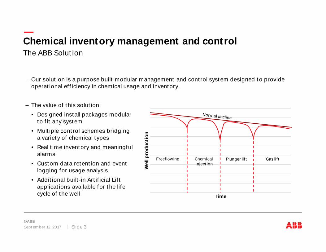
–Our solution is a purpose built modular management and control system designed to provideoperational efficiency in chemical usage and inventory.
–The value of this solution:
• Designed install packages modularto fit any system
• Multiple control schemes bridginga variety of chemical types
• Real time inventory and meaningfulalarms
• Custom data retention and eventlogging for usage analysis
• Additional built-in Artificial Liftapplications available for the lifecycle of the well
The ABB SolutionChemical inventory management and control
Wel
lpro
duc
tion
Time
Freeflowing Chemicalinjection
Plunger lift Gas lift
Hardware
LST100 software configuration
Site wiring – Startup
Control schemes
PCCU – Entry mode
Alarming
Trending
Results
September 12, 2017 Slide 4
Chemical inventory management and control
September 12, 2017 Slide 5
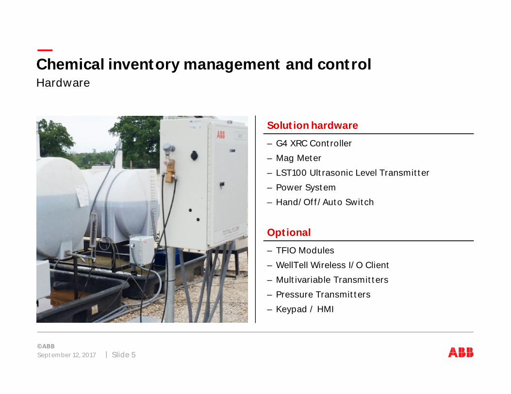
Solution hardware
–G4 XRC Controller
–Mag Meter
–LST100 Ultrasonic Level Transmitter
–Power System
–Hand/Off/Auto Switch
Optional
–TFIO Modules
–WellTell Wireless I/O Client
–Multivariable Transmitters
–Pressure Transmitters
–Keypad / HMI
HardwareChemical inventory management and control

September 12, 2017 Slide 6
Introducing the LST100
Specifically designed for use on chemical tanks, ABB’s LST100ultrasonic level transmitter offers low power, accuratemeasurement at an affordable cost.
This non-contact, easy to install, chemically resistant device letsyou keep track of the most expensive consumable on the padsite; chemicals.
Utilizing ultrasonic technology, you now have the ability to:
–Monitor and inventory every chemical tank in your field
–Alarms in the controller monitoring for leaks
–Refill alarm set points for re-order of product
–Tank fill notifications when the product is delivered
–Volume calculations.
Ultrasonic level for upstream oil & gasChemical inventory management and control
Accurately track andmeasure chemicals, themost expensiveconsumable on your site

September 12, 2017 Slide 7
–The typical human can hear frequencies between 20Hz and 20kHz
–Some medical applications use higher frequencies
–For level measurement we use the frequencies just above human hearing capability
Ultrasonic is sound above human hearing capabilityHow the technology works
20Hz 20kHz 2MHz 200MHz
Low bassnotes
Infrasound Acoustic Ultrasound
LevelMeasurement
Medical

September 12, 2017 Slide 8
The measurement is done by timing the ‘Time of Flight’ of the echoHow the technology works
–A pulse is generated and the time is measured until the echo is received.
–The sensor generates a large pulse
–This pulse bounces back from the target towards the sensor
–Knowing the speed of sound we can now calculate the distance to the surface
Distance
Echo
Transmitted wave

September 12, 2017 Slide 9
–This is a visualization of what the echo would look like on an oscilloscope.
–At position zero on the x-axis is shows the position of the face of the sensor. An echo here wouldindicate a full tank.
–At the ‘Tank Empty’ position, an echo here indicates an empty tank
–The echo shown here shows us where the liquid surface is. In this case it is at about half full.
Introducing the echoMeasurement technique
Tank emptyTank full
Liquidsurface

September 12, 2017 Slide 10
–Here are some examples to show the connection between an echo on the oscilloscope and thelevel in the tank
Introducing the echoMeasurement technique

September 12, 2017 Slide 11
–After generating a pulse, there is a period of time where we have some ringing. This is due to theelectronics and mechanical vibrations that need to settle after being pulsed
–The higher the power, and the longer we pulse, the longer it takes to settle the channel before wecan perform any meaningful measurement
Blanking distanceMeasurement technique
Blankingnoise
Blanking distance is a knowndistance. No echo is accepted as a
measurement before this line.

September 12, 2017 Slide 12
Challenge
–Your chemical tanks are remote, and powered by battery andsolar power
–Common level instruments require too high a voltage andconsume too much power
Solution
–The LST100 was designed to work on a typical 12V solar/batterypower source
–Even when batteries are running low, the instrument is fullyfunctional as low as 9V
Results
–More instruments can be powered per solar panel than with anyother level instrument, reducing your cost of ownership
Designed to run from solar and battery power sourcesLST100 product benefits

September 12, 2017 Slide 13
Challenge
–Ultrasonic level instruments have a blanking distance associatedwith them where no meaningful measurement is possible
–In a small tank of only 3 ft. high, a 1ft. Blanking distance makes itimpossible to measure the top 30% of our application and isunacceptable
Solution
–The LST100 has a specially designed bracket that allows us tomeasure accurately up to 3" from the top of the tank
–Even when above this 3" distance, the instrument reliably detects a‘tank full’ condition
Results
–Have full visibility over the full possible range of your tanks, includingreliable detection of over-fill conditions
Reliable measurement all the way to the top of the tankLST100 product benefits

September 12, 2017 Slide 14
Challenge
–An instrument is required that can survive outdoor. It requires nocover or external housing
–The instrument should be able to survive chemically harshenvironments. No corrosion should take place in the presence ofthese chemicals
Solution
–LST100 is rated IP67 / NEMA 4X. it can survive flooding and roughoutdoor weather conditions. No cover is needed
–The unit is made of PVDF for excellent corrosion resistance. Being incontact with chemicals will not corrode this transmitter
Results
–A robust instrument that will give you many years of service
Made to survive the outdoor and chemical conditionsLST100 product benefits
September 12, 2017 Slide 15
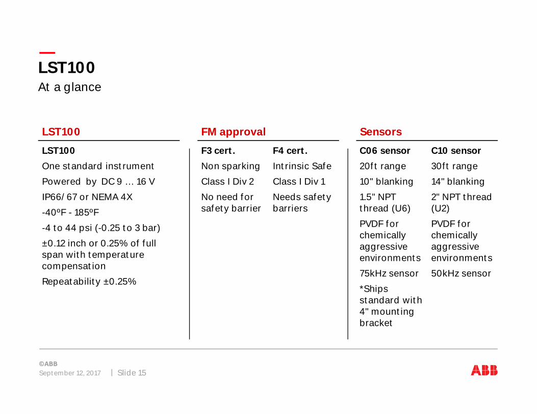
LST100
LST100
One standard instrument
Powered by DC 9 … 16 V
IP66/67 or NEMA 4X
-40ºF - 185ºF
-4 to 44 psi (-0.25 to 3 bar)
±0.12 inch or 0.25% of fullspan with temperaturecompensation
Repeatability ±0.25%
SensorsFM approval
F3 cert.
Non sparking
Class I Div 2
No need forsafety barrier
At a glanceLST100
F4 cert.
Intrinsic Safe
Class I Div 1
Needs safetybarriers
C06 sensor
20ft range
10" blanking
1.5" NPTthread (U6)
PVDF forchemicallyaggressiveenvironments
75kHz sensor
*Shipsstandard with4" mountingbracket
C10 sensor
30ft range
14" blanking
2" NPT thread(U2)
PVDF forchemicallyaggressiveenvironments
50kHz sensor
September 12, 2017 Slide 16
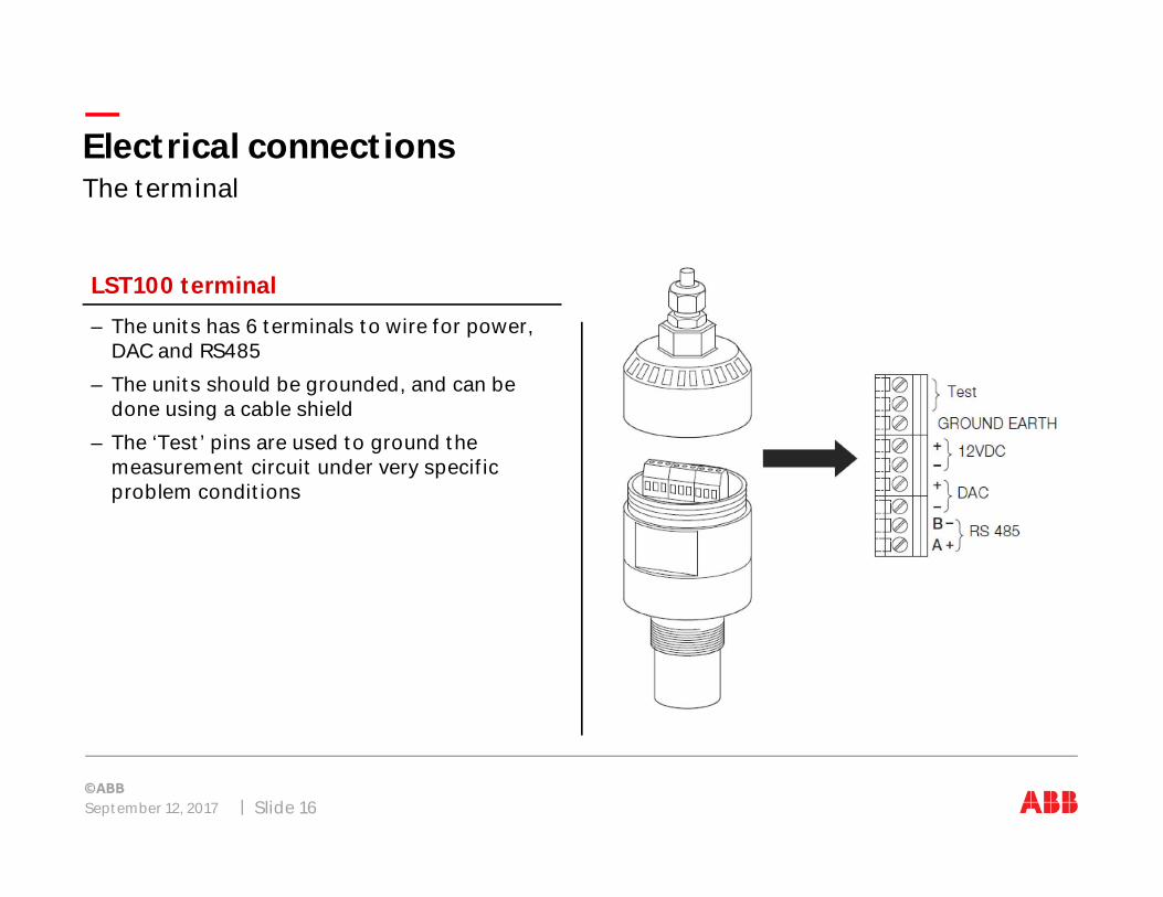
LST100 terminal
–The units has 6 terminals to wire for power,DAC and RS485
–The units should be grounded, and can bedone using a cable shield
–The ‘Test’ pins are used to ground themeasurement circuit under very specificproblem conditions
The terminalElectrical connections

Hardware
LST100 software configuration
Site wiring – Startup
Control schemes
PCCU – Entry mode
Alarming
Trending
Results
September 12, 2017 Slide 17
Chemical inventory management and control

September 12, 2017 Slide 18
Port settings
Bits per second: 9600
Data bits: 8
Parity: Odd
Stop bits: 1
Flow control: None
RS485 via HyperTerminalConnecting to & configuring the unit

September 12, 2017 Slide 19
RS485 via HyperTerminalConnecting to the unit

September 12, 2017 Slide 20
Basic user level
Default username: LST
Default password: 5159
RS485 via HyperTerminalConnecting to the unit

September 12, 2017 Slide 21
Instructions
–The interface is text based.After logging in, you will bewelcomed with thecompany name, devicemodel, serial number etc.
–The main menu is shown,from here you will type anumber and press Enter toenter a section of themenu.
RS485 via HyperTerminalConnecting to the unit

September 12, 2017 Slide 22
Setting the empty distance
RS485 via HyperTerminalConnecting to the unit

Hardware
LST100 software configuration
Site wiring – Startup
Control schemes
PCCU – Entry mode
Alarming
Trending
Results
September 12, 2017 Slide 23
Chemical inventory management and control
September 12, 2017 Slide 24
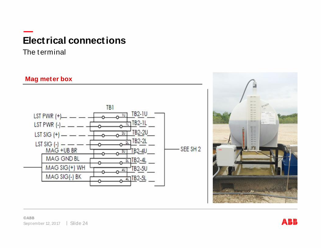
Mag meter box
The terminalElectrical connections

September 12, 2017 Slide 25
Mag meter box / Pump grounds to XRC box
The terminalElectrical connections

Hardware
LST100 software configuration
Site wiring – Startup
Control schemes
PCCU – Entry mode
Alarming
Trending
Results
September 12, 2017 Slide 26
Chemical inventory management and control

September 12, 2017 Slide 27
Mode: Manual – Typical Use: More accurate than timer
Methods of control: Manual ModeControl schemes
2022242628303234363840
500
550
600
650
700
750
800
850
900
1 2 3 4 5 6 7 8 9 10 11 12 13 14 15 16 17 18 19 20
Chem target Flow rate
Flo
wra
te:M
CF/
D
Che
mra
te:Q
ts/D
September 12, 2017 Slide 28
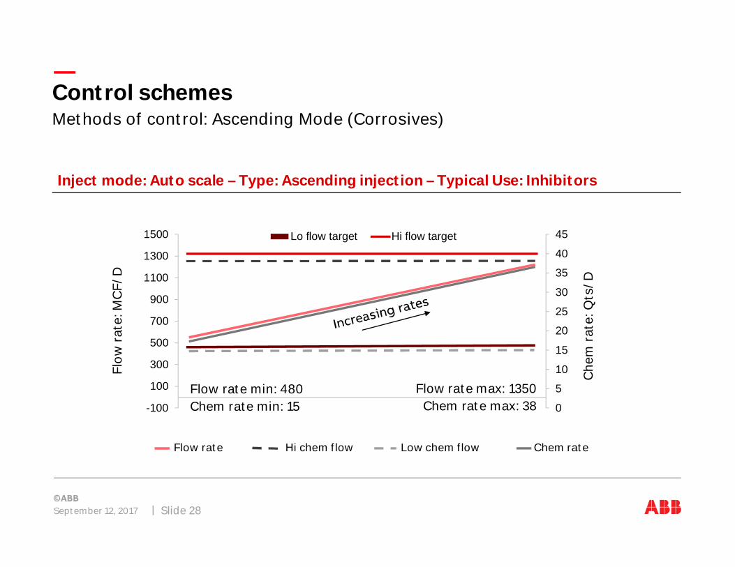
Inject mode: Auto scale – Type: Ascending injection – Typical Use: Inhibitors
Methods of control: Ascending Mode (Corrosives)Control schemes
Flow rate Hi chem flow Low chem flow Chem rate
Flo
wra
te:M
CF/
D
Che
mra
te:Q
ts/D
0
5
10
15
20
25
30
35
40
45
-100
100
300
500
700
900
1100
1300
1500 Lo flow target Hi flow target
Flow rate min: 480Chem rate min: 15
Flow rate max: 1350Chem rate max: 38

September 12, 2017 Slide 29
Inject mode: Auto scale – Type: Descending injection – Typical Use: Foamer agents
Methods of control: Descending Mode (Foamer)Control schemes
Flow rate Hi chem flow Low chem flow Chem rate
Flo
wra
te:M
CF/
D
Che
mra
te:Q
ts/D
05101520253035404550
0
200
400
600
800
1000
1200
1400 Lo flow target Hi flow target
Flow rate min: 600Chem rate min: 20
Flow rate max: 1200Chem rate max: 40
September 12, 2017 Slide 30
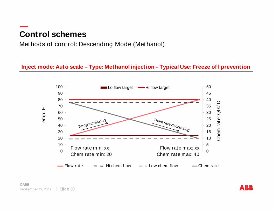
Inject mode: Auto scale – Type: Methanol injection – Typical Use: Freeze off prevention
Methods of control: Descending Mode (Methanol)Control schemes
Flow rate Hi chem flow Low chem flow Chem rate
Tem
p:F
Che
mra
te:Q
ts/D
05101520253035404550
0102030405060708090
100 Lo flow target Hi flow target
Flow rate min: xxChem rate min: 20
Flow rate max: xxChem rate max: 40

Hardware
LST100 software configuration
Site wiring – Startup
Control schemes
PCCU – Entry mode
Alarming
Trending
Results
September 12, 2017 Slide 31
Chemical inventory management and control

September 12, 2017 Slide 32
PCCU setup and register assignmentsChemical inventory management and control

Hardware
LST100 software configuration
Site wiring – Startup
Control schemes
PCCU – Entry mode
Alarming
Trending
Results
September 12, 2017 Slide 33
Chemical inventory management and control

September 12, 2017 Slide 34
–Clogged Alarm – Pump was told to run but no chemical was measured
–Siphon Alarm – Pump was not told to run but chemical was measured
–Low Level Tank – Tank level has gone below low level limit
–Low Battery – Battery voltage has gone below low level limit
–Hand Mode (Pump Priming) – Hand Mode run time > alarm time limit
–Tank Fill Notification – Tank level has risen ‘X’ amount since last update
–Tank Leak Detection – Tank level has decreased > typical operation rate
Versatile alarm system allows for custom alarming to be built
Alarm conditions built into the solutionChemical inventory management and control

September 12, 2017 Slide 35
AlarmsChemical inventory management and control

Hardware
LST100 software configuration
Site wiring – Startup
Control schemes
PCCU – Entry mode
Alarming
Trending
Results
September 12, 2017 Slide 36
Chemical inventory management and control
September 12, 2017 Slide 37
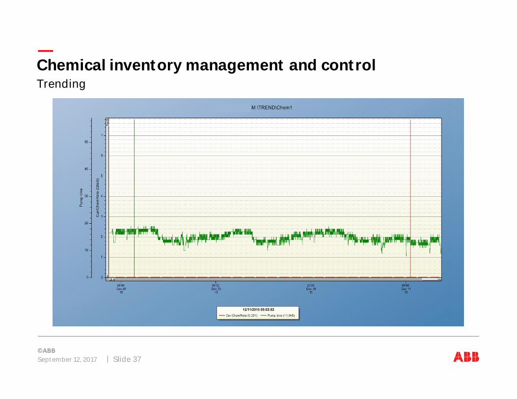
Prebuilt trend variables to track your control, rate and level for process trend history in graph or griddisplay preference.
TrendingChemical inventory management and control
Hardware
LST100 software configuration
Site wiring – Startup
Control schemes
PCCU – Entry mode
Alarming
Trending
Results
September 12, 2017 Slide 38
Chemical inventory management and control
September 12, 2017 Slide 39
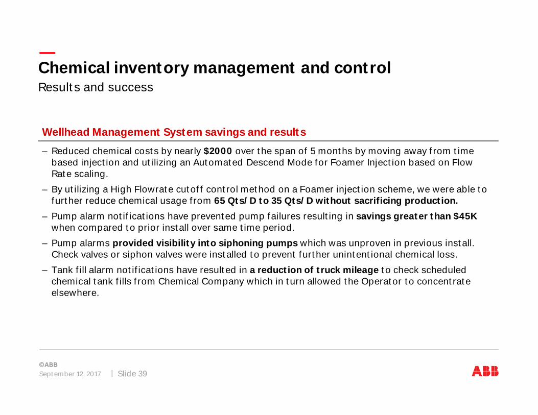
–Reduced chemical costs by nearly $2000 over the span of 5 months by moving away from timebased injection and utilizing an Automated Descend Mode for Foamer Injection based on FlowRate scaling.
–By utilizing a High Flowrate cutoff control method on a Foamer injection scheme, we were able tofurther reduce chemical usage from 65 Qts/D to 35 Qts/D without sacrificing production.
–Pump alarm notifications have prevented pump failures resulting in savings greater than $45Kwhen compared to prior install over same time period.
–Pump alarms provided visibility into siphoning pumps which was unproven in previous install.Check valves or siphon valves were installed to prevent further unintentional chemical loss.
–Tank fill alarm notifications have resulted in a reduction of truck mileage to check scheduledchemical tank fills from Chemical Company which in turn allowed the Operator to concentrateelsewhere.
Wellhead Management System savings and results
Results and successChemical inventory management and control

The information in this document is subject to change without notice and should not be construedas a commitment by ABB. ABB assumes no responsibility for any errors that may appear in thisdocument.
In no event shall ABB be liable for direct, indirect, special, incidental or consequential damages ofany nature or kind arising from the use of this document, nor shall ABB be liable for incidental orconsequential damages arising from use of any software or hardware described in this document.
© Copyright 2017 ABB. All rights reserved.
Important notices
September 12, 2017 Slide 40
