us 2014o190490a1 (19) united states (12) patent ... · integrated oral appliance for...
TRANSCRIPT

(19) United States (12) Patent Application Publication (10) Pub. No.: US 2014/0190490 A1
US 2014O190490A1
WALKER et al. (43) Pub. Date: Jul. 10, 2014
(54) INTEGRATED ORAL APPLIANCE FOR Publication Classification SLEEP-DSORDERED BREATHING
(51) Int. Cl. (71) Applicant: DREAMSCAPE MEDICAL LLC, A6DF 5/56 (2006.01)
Atlanta, GA (US) A6M 16/20 (2006.01) A6M I6/04 (2006.01)
(72) Inventors: Elijah Charles WALKER, Silver (52) U.S. Cl. Spring, MD (US); Anthony P. KIMANI CPC ............ A61F 5/566 (2013.01); A61M 16/0495 MWANGI, Fairburn, GA (US) (2014.02); A61M 16/20 (2013.01)
USPC .......................................................... 128/848 (73) Assignee: DREAMSCAPE MEDICAL LLC,
Atlanta, GA (US) (57) ABSTRACT
(21) Appl. No.: 14/203,791 An integrated oral appliance for treating breathing obstruc tion, Snoring and restriction of the upper airway during sleep
(22) Filed: Mar 11, 2014 with a tongue restraint. Oral appliances of the invention may include an oral cavity engagement device including one or
Related U.S. Application Data more trays, a tongue restraint with a tongue contact portion, a (63) Continuation-in-part of application No. 13/412.209, spring force element operatively coupled between the at least
- 0 one tray and the tongue restraint, wherein the spring force filed on Mar. 5, 2012, which is a continuation-in-part - element is adjustable anteriorly and posteriorly relative to the of application No. 12/273,534, filed on Nov. 18, 2008, tray(s), and an air conduit inside the tongue restraint with a now Pat. No. 8,127,769. front opening of the air conduit extending beyond an anterior (60) Provisional application No. 61/791,702, filed on Mar. end of the tray(s) and a rear opening of the air conduit at a
15, 2013, provisional application No. 60/988,794, filed on Nov. 18, 2007.
posterior end of the of the oral cavity engagement device configured to extend to a posterior Surface of a tongue.

US 2014/O190490 A1 Jul. 10, 2014 Sheet 1 of 13 Patent Application Publication
******--~~~~?…...
se
A. a

US 2014/O190490 A1 Jul. 10, 2014 Sheet 2 of 13 Patent Application Publication
se

Patent Application Publication Jul. 10, 2014 Sheet 3 of 13 US 2014/O190490 A1

US 2014/O190490 A1 Jul. 10, 2014 Sheet 4 of 13 Patent Application Publication
Patent Application Publication Jul. 10, 2014 Sheet 5 of 13 US 2014/O190490 A1

US 2014/O190490 A1 Jul. 10, 2014 Sheet 6 of 13 Patent Application Publication
Patent Application Publication Jul. 10, 2014 Sheet 7 of 13 US 2014/O190490 A1
Patent Application Publication Jul. 10, 2014 Sheet 8 of 13 US 2014/O190490 A1
Azzy 14 Y----- 33

US 2014/O190490 A1 Jul. 10, 2014 Sheet 9 of 13 Patent Application Publication

Patent Application Publication Jul. 10, 2014 Sheet 10 of 13 US 2014/O190490 A1

Patent Application Publication Jul. 10, 2014 Sheet 11 of 13 US 2014/O190490 A1
A 19B e xxxxxxxxxxsswyn

Patent Application Publication Jul. 10, 2014 Sheet 12 of 13 US 2014/O190490 A1
8 '' . Si3
Patent Application Publication Jul. 10, 2014 Sheet 13 of 13 US 2014/0190490 A1
2 -'
aia
SisNA, RESSNs
- o wn -- r
-- wiRELESS LINK
-- ASF, E, FONE, SEE,
NANER
SSNA PRESSNs
www.ra ran as a
as wereLEsslink s ea w - an en - -
uwasareer-es-en-YYYYYYY-r
ASATR
& Actuator (S.S. Nesti E, PJMP
Y- wave
SAN SORAS
CaaaXYYYYYYYY aaawww.rosa-YY
APTOP, CELt. Petone, cious y . . NSAER -- a---
US 2014/O 190490 A1
INTEGRATED ORAL APPLIANCE FOR SLEEP-DSORDERED BREATHING
CROSS-REFERENCE TO RELATED APPLICATIONS
0001. The present application claims benefit of priority to U.S. provisional application 61/791,702, filed Mar. 15, 2013, incorporated by reference herein, and is a continuation-in part of U.S. patent application Ser. No. 13/412.209, filed Mar. 5, 2012, which is a continuation-in-part of U.S. patent appli cation Ser. No. 12/273,534, now U.S. Pat. No. 8,127,769, filed Nov. 18, 2008, which claims the benefit of priority of U.S. provisional patent application No. 60/988,794, filed Nov. 18, 2007, all of which are incorporated by reference herein.
FIELD OF THE INVENTION
0002 The present invention application pertains to oral (i.e. intraoral) appliances for treating, monitoring and report ing sleep-related breathing disorders, as well as non-sleep related disorders. More particularly, this invention applica tion pertains to oral appliances that use multiple methods to enhance breathing during sleep by preventing and alleviating upper airway obstruction and restriction resulting from sleep related breathing disorders such as Snoring, obstructive sleep apnea, obstructive sleep hypopnea, or upper airway resis tance. This invention also pertains to oral appliances that monitor and report information and oral appliances that can provide Substances such as medication and or nutritional Substances.
BACKGROUND OF THE INVENTION
0003 Sleep is a fundamental need and appears to be required for human Survival. However, for many people diag nosed with sleep apnea, going to sleep can be a dreaded experience due to the lack of restful sleep. Sleep apnea (apnea meaning a cessation of airflow) is a relatively common and potentially life-threatening sleep disorder that impacts mil lions of people in the United States and around the world. 0004 Obstructive sleep apnea (OSA), obstructive sleep hypopnea, and upper airway resistance are characterized by upper airway abnormalities that result in airway collapse and complete or partial obstruction of airflow into the lungs. Upper airway (i.e. upper respiratory tract, or airway) abnor malities include: a smaller (than normal) airway cross-sec tional area that Subjects the pharynx to collapse; an enlarged tongue that can obstruct the airway by moving posteriorly (backward) into airway space during sleep; a retruding jaw that can increase tissue pressure Surrounding the airway and Subject it to collapse; an enlarged soft palate that can impinge on airway space when breathing; or compromised pharyngeal dilator muscles that fail to keep the airway open when inhal ing, causing momentary obstruction of airflow. Fortunately, the brain usually detects this inability to breathe and briefly awakens the individual to reopen the airway. Unfortunately, these continuous disruptions in breathing have also been associated with increased blood pressure, stroke, and diabetes as well as other chronic disorders including death. Due to the variety of airway abnormalities that cause obstruction, and individual needs and preferences, no single solution has been found to be acceptable to all who suffer from OSA.
Jul. 10, 2014
0005 Forced Ventilation Approaches 0006 Various apparatus-based approaches (e.g. non-sur gical and non-pharmacological) have been developed to treat Snoring and/or sleep apnea which in general can be divided into two categories: 1. apparatus that require a power Source and 2. apparatus that do not require a power source. Airway Pressure apparatus that require power sources (usually involving forced ventilation) include medical devices, such as Continuous Positive Airway Pressure (CPAP) devices, and negative pressure apparatus. Although CPAP devices have success rates of approximately 82.7% (Hoekema A, et al. “Obstructive Sleep Apnea Therapy”, J Dent Res. 2008 Sep tember 87(9):882-7), they suffer from low user compliance estimated to be approximately "25-50% with patients typi cally abandoning therapy during the first 2 to 4 weeks of treatment’: (ZoZula, R. et al. Compliance with continuous positive airway pressure therapy . . . . Current Opinion in Pulmonary Medicine. 7 (6): 391-398, November 2001). Those who dislike CPAP give many reasons including: mask discomfort, difficulty adapting to the pressure, dislike being tethered to a machine, nasal irritation, Sore throat, and aller gies. 0007 Current Oral Appliance Approaches 0008 Current oral appliance approaches offer additional Solutions for Snoring or sleep apnea. Oral appliances can generally be separated into two types: Mandibular Reposi tioning Appliances, (e.g. U.S. Pat. No. 6,729,335, Halstrom, May 4, 2004) and Tongue Retainer appliances. Mandibular Repositioning Appliances (MRAS, Sometimes known as mandibular advancement appliances) purport to reposition the mandible anteriorly to further open the airway to prevent its obstruction. 0009 Traditional Tongue Retainer (TR) appliances are not used very often, and in general, they either use a medium Such as a Suction to hold/pull the tongue or they use a direct contact device to hold/restrain the tongue during sleep. Suction-type TRS may be recommended when users lackadequate teeth or when the lower jaw can’t be advanced. One vacuum-type TR. (U.S. Pat. No. 4,676,240, Gardy, Jun. 30, 1987) purports to provide a way to hold the tongue forward in a chamber that generates a vacuum when the tongue begins to fall and also purports to allow oral breathing. 0010. A direct contact type of TR (e.g. U.S. Pat. Applica tion Pub. 2008/0041396 A1, Lucker, Jan. 21, 2008) purports to restrain the tongue using a rigid flat tab at the back of the tongue and uses another rigid tab-like component in the area of the soft palate. Another TR appliance (e.g. U.S. Pat. No. 6,766,802, Keropian, Jul. 27, 2004) purports to hold the tongue down using a rigid bar-like device. (0011 Shortcomings of Prior Art 0012 Prior art offers a variety of purported solutions along with significant drawbacks. Oral appliances (MRA, TR, etc.) in general have treatment success rates of approximately 54%, and compliance rates of 56-68%. (Hoffstein V. “Review of oral appliances for treatment of sleep-disordered breath ing, Sleep Breath. 2007 March; 11(1):1-22). MRA users have experienced mixed success, with some patients experi encing potentially harmful dental changes and/or temporo mandibular joint pain. A study reported that with long term use (88.4+/-26.7 months) there were significant dental changes including “mandibular arch width increased more than maxillary arch width' (Chen H. et al., “Three-dimen sional . . . Part 2. Side effects of oral appliances . . . . Am J Orthod Dentofacial Orthop. 2008 September; 134(3):408 17).

US 2014/O 190490 A1
0013 Pre-fabricated thermoplastic (boil and bite) MRAs have been determined to be ineffective and “cannot be rec ommended as a therapeutic option nor can it be used as a screening tool to find good candidates for mandibular advancement therapy” (Vanderveken, OM, et al., “Compari Son of a custom-made and a thermoplastic oral appliance for the treatment of mild sleep apnea.’. Am J Respir Crit Care Med 2008; 178:197-202). 0014 Vacuum-type TR devices that purport to hold the tongue suffer from low compliance rates, reported to be 25% in one study (e.g. 75% non-compliance) and low efficacy i.e. low treatment success, (Schonhofer, Betal, “Value of various intra- and extraoral therapeutic procedures for obstructive sleep apnea and snoring'. Med Klin (Munich, 1997 Mar. 15: 92 (3): 167-749173209). 00.15 Part of the difficulty of restraining or holding the tongue is due to the typically wet, slippery nature of the tongue. Saliva is continuously produced in the oral cavity at a rate of approximately 1.5 liters per day, which increases when foreign objects are added. Additionally, glycoproteins in saliva (which provide its lubricative characteristic), increase the difficulty of holding the tongue. 0016. Thus, there remains a need for a treatment apparatus that does not require forced ventilation, or being tethered, and is effective in restraining intraoral tissue including the tongue and or mandible without adverse effects such as discomfort, pain, tissue dysfunction, or injury. 0017. It would be advantageous to provide an effective oral appliance to maintain upper airway patency during sleep, thus preventing obstructions and Snoring without adverse effects. 0018. It would be advantageous to provide an oral appli ance to maintain airway patency comprising mandible repo sitioning and tongue restraint to improve treatment effective ness and comfort. 0019. It would be advantageous to provide an oral appli ance comprising a comfortable, easily adjustable mandible repositioning method. 0020. It would be advantageous to provide an oral appli ance comprising bristles and or other materials or means to interact with the tongue without excessive force. 0021. It would be advantageous to provide an oral appli ance comprising an air conduit to provide breathable air via the oral cavity while keeping the mouth closed thus bypassing upper airway obstructions and nasal restrictions. 0022. It would be advantageous to provide an oral appli ance comprising a means to provide Substances such as medi cations and or nutritional Substances. 0023. It would be advantageous to provide an oral appli ance that can be located and maintained in the oral cavity using a variety of means. 0024. It would be advantageous to provide an oral appli ance that can detect, monitor, and report physiological vari ables inside the oral cavity. 0025. It would be advantageous to provide an oral appli ance that can electromechanically interact with oral cavity tissue. 0026. The aforementioned and other advantages, features and characteristics of the present invention, as well as the methods of operation and functions of the related elements of structure and the combination of parts and economies of manufacture, will be more apparent upon consideration of the following detailed description and claims, with reference to the accompanying drawings; all of which form a part of this
Jul. 10, 2014
specification, wherein like reference numerals designate cor responding elements in the various figures. It should also be understood that the drawings are for the purpose of illustra tion and description and are not intended to specify the limits of the invention. Nor is the size, scale or orientation of ele ments shown in the drawings intended to reflect actual size, scale or proportion. Additionally, the method of the present invention includes any description herein of how the appara tus functions or is used, irrespective of whether Such descrip tion is specifically identified as method disclosure.
SUMMARY OF THE INVENTION
0027. In accordance with the present invention, a unique oral appliance integrates several novel features to secure the device in the oral cavity, treat, detect, and monitor sleep related breathing disorders associated with upper airway abnormalities and Snoring or other disorders or conditions that can be treated via the oral and or nasal cavity. The appli ance is placed in the oral cavity and Supported by engaging oral cavity tissue such as upper and or lower dentition, gin giva, or mucosa Such as labial and or buccal mucosa and or Supported by means external to the oral cavity. The appliance can use a variety of means to engage oral tissue, and/or teeth including without limitation holding, contacting, frictional force. Suction, gripping, captivating, and like engagement means. In some embodiments, standard-sized or custom fit trays may engage oral tissue and/or teeth. In other embodi ments, standard-sized or custom fit engagement compounds may be utilized to support the positioning of an oral appliance of the present invention. 0028. An oral appliance in embodiments of the invention can be implemented in a variety of ways to treat a variety of conditions and can comprise a means to locate and secure the device in the oral cavity, a means to advance the mandible, a means to interact with the tongue, a means to allow airflow via the oral cavity, a means to humidify and/or heat the oral cavity, and/or a means to provide medication or nutritional Substances. A means can also be provided to connect other devices (such as CPAP devices), or power or methods to secure the oral appliance to the user. Adjustable components facilitate movement of the lowertray to advance the mandible to prevent upper airway closure. Other attached components interact with the tongue to blocktongue movement or to apply a compressive spring-loaded, or magnetic, or fixed force to the surface of the tongue. Novel interface (such as bristles, non-slip, or anti-slip materials, or active and non-active com ponents) engage the tongue to prevent it from obstructing the airway. A novel air conduit allows breathable air or other fluids to flow (via the oral cavity) to the upper airway, bypass ing nasal restrictions and/or airway obstructions and modu lates upper airway air pressure. Means is also provided to humidify and or heat the air cavity. Means are also provided to treat other (sleep related or non-sleep related) disorders or conditions using medications, nutritionals, and like Sub stances. Means are also provided to detect, monitor, Store and report physiological data involving the oral cavity and or upper airway.
BRIEF DESCRIPTION OF THE DRAWINGS
0029. A complete understanding of the present invention may be obtained by reference to the accompanying drawings, when considered in conjunction with the Subsequent, detailed description, in which:

US 2014/O 190490 A1
0030 FIG. 1 is a left sectional view of an anatomical cross-section of a normal human upper airway including nasal cavity, oral cavity, and pharynx with arrows illustrating normal nasal airflow: 0031 FIG. 2 is a left sectional view of an anatomical cross-section illustrating occlusion of the pharynx that can occur during obstructive sleep apnea; 0032 FIG.3 is a rear perspective view of an integrated oral appliance in an embodiment of the present invention; 0033 FIG. 4 is a rear exploded perspective view of an integrated oral appliance in an embodiment of the present invention; 0034 FIG.5 is a rear right partial view of an oral appliance illustrating a coupling for providing advancement of a lower tray relative to an uppertray in one embodiment of the present invention; 0035 FIG. 6 is a rear right partial view of an oral appliance illustrating a coupling for providing advancement of a lower tray relative to an uppertray in one embodiment of the present invention; 0036 FIG. 7 is a rear perspective and partial view of a connector between trays of an oral appliance in one embodi ment of the present invention; 0037 FIG. 8 is a rear perspective view of an oral appliance in one embodiment of the present invention; 0038 FIG. 9A is a rear perspective view of upper and lower trays of an oral application in one embodiment of the present invention; 0039 FIG.9B is a top view of an upper tray of an oral appliance in one embodiment of the present invention; 0040 FIG. 10 is a left sectional view of an anatomical cross-section of a human upper airway and oral appliance engaging upper and lower dentition and coupled to a tongue in one embodiment of the present invention; 0041 FIG. 11A is a rear perspective view of an uppertray and lower tray of an integrated oral appliance with a tongue restraint in one embodiment of the present invention; 0042 FIG. 11B is a perspective view of a tongue restraint with a perspective view of air conduit in one embodiment of the present invention; 0043 FIG. 11C is a perspective view of a tongue restraint of an oral appliance in one embodiment of the present inven tion; 0044 FIG. 12 is a rear perspective view of an upper tray and lower tray of an integrated oral appliance having a con nector to a Support strap in one embodiment of the present invention; 0045 FIG. 13 is a front perspective view of an assembly comprising an air conduit, humidification means, and adjust able tongue-restraint in one embodiment of the present inven tion; 0046 FIG. 14 is a front perspective view of a retainer with air conduit in one embodiment of the present invention; 0047 FIG. 15 is a perspective view of a tray to engage dentition that includes an air conduit in one embodiment of the present invention; 0048 FIG.16 is a left perspective and partial view of a tray of an oral appliance having Suction cups, shown in a cross sectional detail view, in one embodiment of the present inven tion; 0049 FIG. 17 is a perspective view of a spring air conduit and a fluid absorbent material of an oral appliance in one embodiment of the present invention;
Jul. 10, 2014
0050 FIG. 18 is an oral appliance with electronic compo nents in one embodiment of the present invention; 0051 FIGS. 19A and 19B are perspective views of an electronic means to detect breathing rate within an oral appli ance air conduit by sensing a change in light transmission during inhalation (FIG. 19A) and exhaling (FIG. 19B) in one embodiment of the present invention; 0.052 FIG. 20 is a schematic view of an optical source and detector mounted within a dental tray 1 that engages a lip as part of a system to determine heart rate and or oxygen Satu ration in one embodiment of the present invention; 0053 FIG. 21 is a left cross-sectional view of a human upper airway illustrating an oral appliance positioned in the oral cavity, engaging the upper and lower dentition, and inter acting with the tongue using electronic means to prevent it from obstructing the airway in one embodiment of the present invention; 0054 FIG. 22 is a relational block diagram illustrating electronic monitoring of sensors of an oral appliance and data collection in one embodiment of the present invention; 0055 FIG. 23 is a relational block diagram of a switch, clock and display for usage monitoring of an oral appliance in one embodiment of the present invention; 0056 FIG. 24 is a relational block diagram of electronic monitoring and data collection of an oral appliance having an electronic actuator control including tongue control, motor, pump, valve, and the like, in one embodiment of the present invention;
DESCRIPTION OF THE PREFERRED EMBODIMENT
0057 Accordingly, the preferred embodiment of the present invention comprises several unique features designed to overcome upper airway abnormalities experienced by those who suffer from sleep-related breathing disorders such as obstructive sleep apnea and Snoring. Specifically, the inte grated oral appliance 13 treats disorders such as obstructive sleep apnea and Snoring by preventing or mitigating airway closures by advancing the mandible to further open the air way, providing an air conduit 8, engaging the tongue, provid ing medication to treat sleep apnea or other disorders, and monitoring and reporting device usage as well as other physi ological variables. The present invention, as well as a pre ferred mode of use, objects and advantages, can be under stood by referring to the following detailed description when read in conjunction with the accompanying drawings, wherein: 0.058 FIG. 1 is an anatomical cross-section of a normal human upper airway including nasal cavity, oral cavity, and pharynx with arrows illustrating nasal airflow: 0059 FIG. 2 is a view similar to FIG. 1, illustrating occlu sion of the pharynx that can occur during obstructive sleep apnea; 0060 FIG.3 is a rear perspective view of an integrated oral appliance 13; 0061 FIG. 4 is a rear exploded perspective view of an integrated oral appliance 13 illustrating the following ele ments:
0062) i. Element 1 an uppertray to engage dentition and oral tissue comprising a means to connect Support ele ments 10 and a means to provide anterior/posterior adjustment of elements 9 by moving elements 9 to dif ferent holes positioned on the sides of element 1;

US 2014/O 190490 A1
0063 ii. Element 2 a lowertray to engage dentition and oral tissue comprising a means to connect elements 9 to the lower tray:
0064 iii. Both elements (trays) 1 and 2 can be made from a variety of biocompatible materials (e.g. acrylic, thermoplastics such as ethylene vinyl acetate, thermo plastic elastomer such as VistamaxxTM, ExxonMobil Chemical; or Variflex, Great Lakes Orthodontics, poly meric materials, or medical-grade silicone rubber, or any appropriate material that will functionally perform and will not rust or degrade when exposed to the environ ment inside the oral cavity. In other embodiments, trays 1 and 2 may facilitate inclusion of additional compo nents such as a built-in air vent or electronic components etc. In other embodiments, elements 1 or 2 may be Supported by means exterior to the oral cavity including straps connected via means around the head or neck or ears etc., or clamp to a body Surface Such as the nose. In other embodiments elements 1 and 2 may be fastened together or constructed as a single unit. In other embodi ments, additional means can be used to adjust element 1 relative to element 2 in an anterior/posterior direction such as illustrated in FIG. 5, where hook and loop fas tener elements 51 and 52 attached to the outer surface of elements 1 and 2. Alternatively, as illustrated in FIG. 6, a curved rod element 61 may be fixed to element 1 and element 62 adjustably connects element 2 to element 1 to allow element 2 to be adjusted anteriorly relative to element 2. In other embodiments, means can be pro vided to adjust the vertical spacing between elements 1 and 2. In other embodiments as illustrated in FIG. 7, element 1 and connecting rods 10 can be replaced using dental tray sections, elements 71 and 72 connected with element 73. Elements 71 and 72 can be made using VistamaxxTM, ExxonMobil Chemical. Elements 73 can be made using an appropriate biocompatible rigid mate rial Such as stainless steel or polymeric materials etc.
0065 iv. Element 3 provides spring-force to engage the tongue and connects adjustably to element 6 on one end using a tabbed surface that fits into slots on the bottom surface of element 6, and fastened (or fixed) to element 4 on the lower end. In other embodiments, other means can be provided to adjust element 3 in an anterior/pos terior direction thus adjusting its position on the tongue. For example, threaded fasteners can also be used. In other embodiments, element 3 can be positionally non adjustable. In other embodiments, the spring-force range exerted by element 3 can be fixed or adjustable. Element 3 can be fabricated from a material that is biocompatible, lightweight, strong enough to perform said tongue engaging function, and able to endure mul tiple flexures over the lifetime of integrated oral appli ance 13. Element 3 can be made using an appropriate stainless spring steel or a wide variety of other appro priate spring materials including polymeric materials or elastomeric materials, or any appropriate material that will functionally perform and will not rust or degrade when exposed to the environment inside the oral cavity. In other embodiments a variety of spring types can be used Such as torsion springs, leaf springs, coiled springs, compression or extension springs, constant force springs, wire-form springs, cantilevered springs, or cus tom stampings, and the like. In other embodiments a variety of means can be used to provide a spring-force
Jul. 10, 2014
including pneumatics, elastomeric means such as rubber or foam blocks such as in FIG. 11 element 110 or ele ment 111, magnetic means including opposing magnetic fields. In other embodiments a non-spring force, for example a fixed weight or rigid element can be posi tioned on the tongue. In other embodiments a rigid ele ment can be pressed against the tongue to block its movement as shown in FIGS. 11A-C, element 111 or to compress the tongue using a rigid material. Note that element 111 (FIG. 11C) can be rigid and block tongue movement at the base of the tongue (or other location on the tongue) or provide a spring-force to restrain tongue movement. Note that element 110 (FIGS. 11A and 11B) can be a rigid material or a spring-force material;
0.066 v. Element 4 is an enclosure and comprises part of air conduit 8 and is connected to element 3 and Supports element 5. Element 4 can be made of an appropriate biocompatible material including polymeric, foam, rub ber, stainless steel, etc. In other embodiments element 4 can be open and be an extension of element 3 and pro vide support for elements 8 and 5. Element 4 can also provide a platform to support electronics, actuators, or medication, etc;
0067 vi. Element 5 serves to engage the tongue and mounts on element 4 (or can be fabricated as a part of element 4) and serves to engage the tongue to mitigate tongue movement. As illustrated, element 5 is made as a band with an array of fiber type projections on the bot tom surface that engages the tongue and maintains con tact with the tongue under a compressive force that is Sufficient to keep the fibers engaged with the tongue to properly restrain it, but not excessive to cause pain or injury. Element 5 may comprise a variety of materials including but not limited to materials such as medical grade or food grade silicone rubber, foam, gel, Vis tamaXXTM, polymers, polymeric, elastomeric, compos ite materials, metals, material blends, and the like; or slip-resistant materials, or any appropriate material that will functionally perform and will not rust or degrade when exposed to the environment inside the oral cavity. Element 5 can also be made in a variety of configurations including an array of pores or reliefs, a mesh or irregular or corrugated Surface, cavities, a porous matrix, perfo rations, gratings, and the like;
0068 vii. Element 6 provides support for spring-force element 3 and adjustment of element 3, support for connecting elements 10, Support for element 8, and a support means for element 7 to secure element 3 within element 6. Element 6 is fabricated to fit a range of element 1 arch widths using the appropriate size con necting elements 10. Element 6 can also provide a means to mount additional components including electronics or medication Supplies;
0069 viii. Element 7 can be fastened into element 6 to secure element 3 within element 6. Element 7 also sup ports one end of the forward-most element 10. Element 7 can be fabricated using a variety of appropriate mate rials including stainless steel, or polymeric materials etc.;
0070 ix. Element 8 serves as an air conduit that is mounted between elements 1 and 2, and fits between the users lips and connects to element 6 and 4 and 5 to vent air from outside the users lips to inside the oral cavity or inside the upper airway. Airflow within the air conduit 8

US 2014/O 190490 A1
occurs naturally as the user inhales and exhales. When the user inhales, a negative pressure is developed within the pharynx (near the end of element 5), causing air to flow from higher pressure (atmospheric pressure) out side the user's oral cavity directly to the user's pharynx. Airflow is reversed when the user exhales. Element 8 can be fabricated using a variety of appropriate materials including elastomers such as silicone rubber, stainless steel, polymeric materials, foam etc. In other embodi ments element 8 can be made of fixed length or adjust able length using telescoping sections, or fixed diameter or adjustable diameter, or can be made using a variety of shapes including oval, round, rectangular, square etc, or in other embodiments the air conduit can be perforated to allow moisture to be added to the air. In other embodi ments a flow control device (e.g. mechanical or electro mechanical valve) can be included to adjust the flow rate ofair orgas etc. In other embodiments other features can be included Such as a venturi, or one-way valves, or a provision to allow other substances to be conveyed within the air vent such as ports to allow medication etc. In other embodiments additional components can be connected to element 8 to allow forced air devices to be connected. In other embodiments additional connectors can be added to element 8 to allow connection to outside Support means Such as straps, clamps, etc. In other embodiments element 8 may be incorporated as a part of other components such as element 1 or 2, or as a separate device as shown in FIG. 15 where element 150 includes an air vent and a means to engage the tongue. In other embodiments a coiled spring can serve as an air vent when covered by a tube such as illustrated in FIG. 17 where coiled spring 172 is covered by a tube (foam or elastomer). In other embodiments a means to humidify the air can be included such as shown in FIG. 17 where a foam tube element 171 contains a liquid that serves to humidify air flowing through the coiled spring, or the coiled spring can be replaced by a perforated tube. In other embodiments the air conduit can provide multiple functions and serve as a means to engage the tongue as well as a means to convey air. In other embodiments the air conduit 8 can convey other gases or forced air from CPAP devices or other substances such as medication. In other embodiments the air conduit can assist in provid ing Positive End-Expiratory Pressure (PEEP) through appropriate configuration of valves. In another embodi ment aheating element such as resistive element can be provided to heat inhaled air. In another embodiment the air conduit 8 can be eliminated if not required;
0071 x. Elements 9 are rigid links to connect elements 1 and 2 and can be repositioned using elements 11 to move elements 9 to a different hole on the sides of element 1. Elements 9 serve to reposition element 2 thus moves the users mandible. Element 9 can be made using a variety of appropriate materials including stainless steel or polymeric materials;
0072 xi. Element 10 are support rods to connect ele ment 6 to element 1 (or element 2). The rods are sized to connect a wide variation in element 1 arch widths. The rigid rods can be screwed into the interior face of ele ment 1. The rods can be fabricated using a variety of biocompatible materials including stainless Steel, or polymers etc. Although (3) element 10 rods are illus trated to connect to element 6, other embodiments can
Jul. 10, 2014
comprise connections to element 1 using one or two connecting elements to connect to elements 1 or 2 and Support additional components. In other embodiments elements 10 can be made using a single piece of stainless spring Steel that forms a bridge that is connected to (2) inner Surfaces of element 1 and is appropriately shaped to form a curved cantilever spring to engage the tongue, and Support element 8:
0073 xii. Element 11 are fasteners to connect elements 9 to elements 1 and 2 and can be made using a variety of appropriate materials such as stainless steel, or nylon, or other polymeric materials;
0074 xiii. Element 12 is a fastener used to connect one end of element 3 to an end of element 4. Element 4 can be made using a variety of appropriate materials such as stainless steel, or nylon, or other polymeric materials. In other embodiments element 12 can be another type of fastener or can be eliminated if element 3 is built into element 4.
0075. In operation, an appropriate medical professional (e.g. physician, dentist, etc.) can initially fit and adjust the integrated oral appliance 13 to the user oral cavity. Initial one-time adjustments can include mandible repositioning and positioning of tongue-restraint assembly, components 3. 4, 5, to engage the users tongue. The mandible is moved (repositioned) by moving the part of element 9 that is attached to the side of element 1 to a different hole location on element 1 of FIG. 4. The tongue restraint (or tongue stabilizer (as sembled elements 3, 4, 5) is positioned on the tongue by removing element 7 and then moving element 3 within ele ment 6 to the proper position within element 6 of FIG. 4 so that the elements 3, 4, 5 are in a new location on the user's tongue.
0076. In daily practice, prior to falling asleep, the user positions the integrated oral appliance 13 inside their oral cavity so that upper-tray1 and lower-tray 2 engages dentition and the assembly 3, 4, 5 engages the tongue. During sleep, the oral appliance mitigates obstructive sleep apnea and Snoring by advancing the mandible (if necessary) to further open the airway, engaging the tongue to prevent it from obstructing the upper airway, allowing an alternative air path (element 8) via the oral cavity which also serves to reduce pharyngeal col lapse pressure near the tongue and soft palate, and may treat other conditions via medication. After waking up, the user removes the oral appliance from their oral cavity and cleans it using an appropriate method. If the oral appliance comprises electronics (FIG. 18) the user may also transfer data. 0077. Thus, it can be seen from the above illustrative embodiments that key elements of the integrated oral appli ance 13 interact with upper airway tissue to treat upper airway abnormalities that cause obstructions during sleep. When positioned in a user's mouth (oral cavity), the integrated oral appliance 13 restrains the tongue, preventing the tongue from moving into airway space; moves the mandible in an anterior (forward) direction to open the airway; and reduces tissue pressure to improve airflow. The present invention also pro vides an air conduit to bypass nasal restrictions and or airway obstructions if they occur. 0078. In an actual reduction to practice an oral appliance of the present invention, the present invention reduced the Apnea Hypopnea Index from 29 (untreated) to 1 and elimi nated Snoring.

US 2014/O 190490 A1
ADDITIONAL EMBODIMENTS
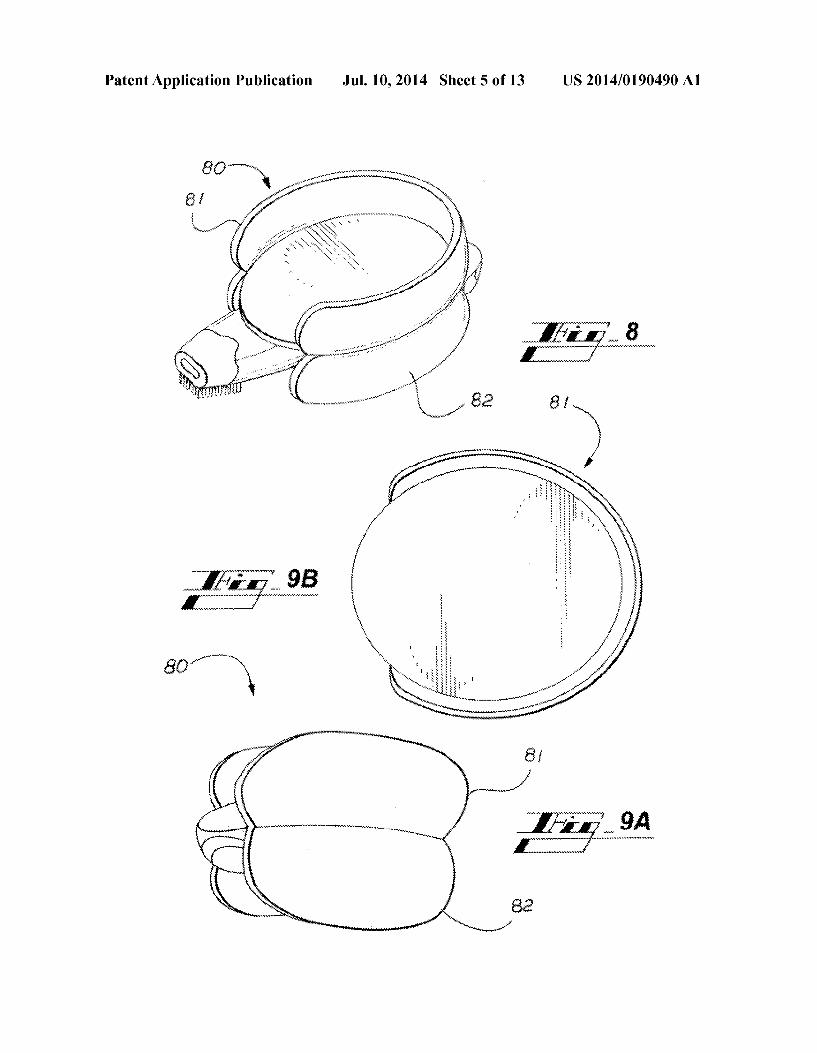
0079. It should be obvious to those skilled in the art that there area wide variety of changes that can be made to either the integrated oral appliance 13 or its method of manufac ture. In one alternate embodiment, the present invention can be made with only one of the key features such as with tongue restraint only or with mandible advance only. In another embodiment tongue restraint can be accomplished with attachment to upper dentition or lower dentition using either the upper-tray 1 alone or the lower-tray 2 alone. Tongue restraint can also be accomplished without an internal air conduit 8 if an alternate breathing passage is not required. In other embodiments there can be variations in adjustable fea tures Such as adjustable spring force or the type of spring used. In another embodiment element 5 can be replaceable to accommodate wear or made out of a different material that also has non-slip properties. In other embodiments there can be variations in the method of mandible adjustment. 0080. In further embodiments, other attachment, support and/or engagement alternatives for coupling a tongue restraint may be provided to trays coupling to a dentition. Coupling elements to Support the tongue restraint may include one or more Supports or attachments for placement in one or both of inside and outside the oral cavity. Coupling elements for positioning the tongue restraint in some embodi ments may include wires (including but not limited to engag ingaportion of dentition), straps, bracings, grips, and the like. It will be appreciated that in such alternative embodiments the supports external or internal of the oral cavity are generally provided for comfortable fitting to the user. 0081 FIG. 5 is a rear right section of an oral appliance illustrating an alternative embodiment for coupling uppertray 1 to lowertray 2 and advancing lowertray 2 relative to upper tray 1. Components 51 and 52 are medical grade hook and loop fasteners fabricated from appropriate polymeric or poly meric materials. 0082 FIG. 6 is a rear right section of an oral appliance illustrating an alternative embodiment for coupling uppertray 1 to lowertray 2 and advancing lowertray 2 relative to upper tray 1. Component 61 is a rigid curved rod attached to com ponent 1 and enables component 62 (attached to 2) to facili tate advancement of component 2. Components 61 and 62 can be made using stainless steel or composite or polymeric mate rials, or any appropriate material that will functionally per form and will not rust or degrade when exposed to the envi ronment inside the oral cavity. 0083 FIG. 7 is a rear perspective view of an alternative embodiment to engage oral tissue using trays 71 and 72 comprised of VistamaXX or other appropriate materials, con nected with component 73. Component 73 is a support sized to fit the users dental arch and can be made using stainless steel or composite or polymeric materials, or any appropriate material that will functionally perform and will not rust or degrade when exposed to the environment inside the oral cavity. 0084 FIG. 8 is a rear perspective view of oral appliance 80 illustrating an alternative embodiment to engage oral tissue including dentition and gingiva and the oral vestibule. Oral appliance 80 comprises elements 81 (uppertray), element 82 (lower tray) (see FIG.9A), and elements 3 through 8 and 12 (see FIG. 3). Oral appliance 80 does not provide a means to reposition the mandible. Oral appliance 80 does provide an adjustable spring force, and adjustable location for spring element 3. Uppertray 81 and lowertray 82 can be made using
Jul. 10, 2014
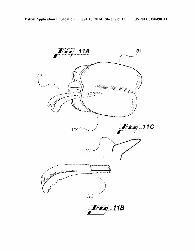
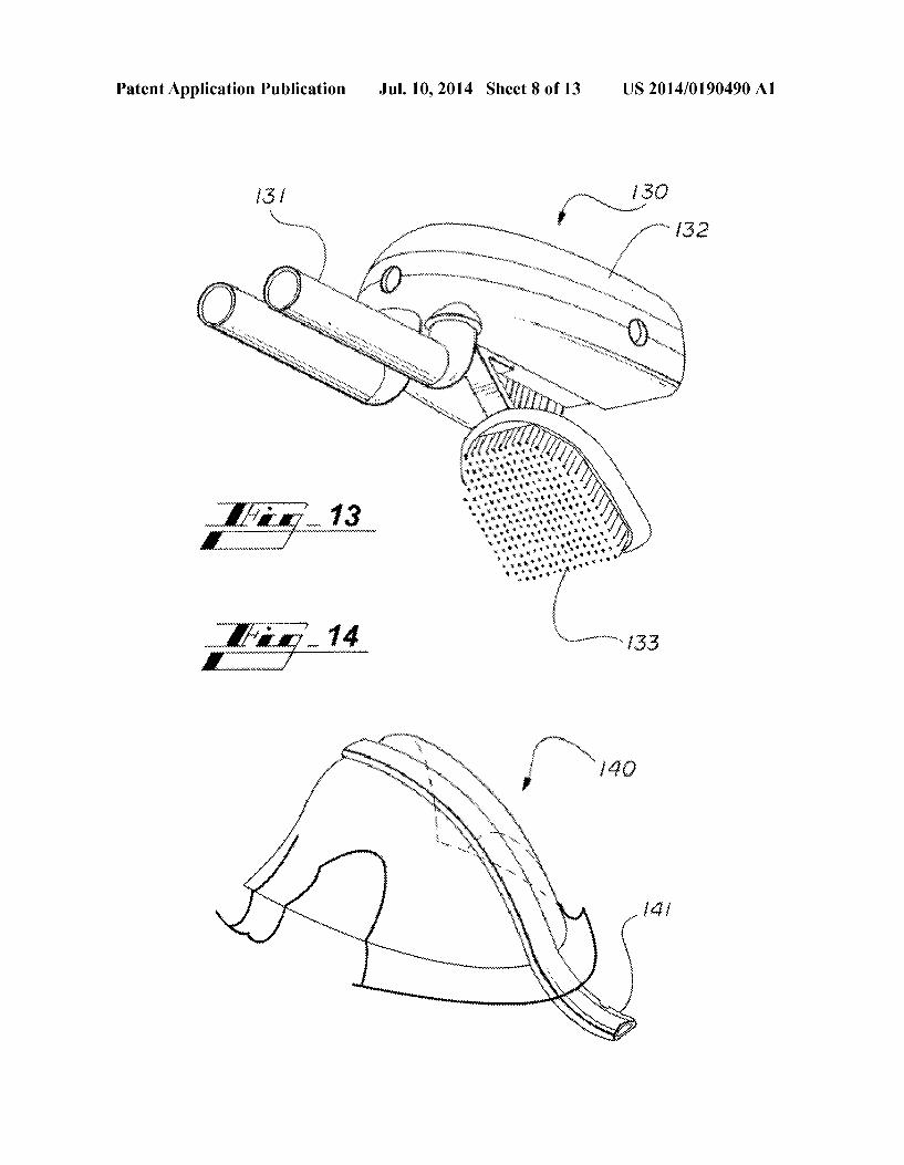
flexible rubber materials, VistamaxxTM, composite or flexible polymeric materials, or any appropriate material flexible or semi-flexible material that will functionally perform and will not rust or degrade when exposed to the environment inside the oral cavity. Upper tray 81 also includes a relieved area in the middle of its upper surface to allow space for the frenu lum. In an alternative embodiment upper tray 81 and lower tray 82 can also be made so that upper tray 81 and lowertray 82 are adjustable using expandable approaches Such as cor rugated materials, or heat sensitive materials that can be expanded to fit within the users oral vestibule. Additional embodiments of trays 81 and 82 can incorporate additional means to engage dentition similar to trays 1 and 2 of FIG. 4 to prevent superior/inferior movement of oral appliance 80 if the user's mouth opens during sleep. Trays 81 and 82 can also be made as a single element instead of two elements fastened together. I0085 FIG. 9A is a rear perspective view of oral appliance 80, including trays 81 and 82 and FIG.9B is a top view of upper tray 81. 0.086 FIG. 10 is a left sectional view of an anatomical cross-section of a human upper airway (similar to FIG. 1), illustrating a cross-section of oral appliance 80 positioned in the oral cavity, engaging the upper and lower dentition, and interacting with the tongue to prevent it from obstructing the airway. I0087 FIG. 11A is a rear perspective view of uppertray 81 and lowertray 82 of an integrated oral appliance 80 compris ing an alternative embodiment of a tongue restraint 110, as shown separately in FIG.11B connected to air conduit 8. FIG. 11C is a perspective view of component 111 illustrates an alternative embodiment to component 110 that engages the tongue. I0088 FIG. 12 is a rear perspective view of upper tray 81 and lowertray 82 of an integrated oral appliance 80 illustrat ing attachment of connector 120 to tray 82 and additional support strap 121. Strap 121 provides a means to stabilize the oral appliance during sleep and can be made using a variety of flexible materials including silicone rubber, polymeric mate rials, composite materials and the like. Strap 121 can also be used to comprise other materials, Substances, or components Such as including, but not limited to, wires, electronics, medi cations, and the like. I0089 FIG. 13 is a front perspective view of an alternative embodiment of an assembly 130 comprising an air conduit 131, humidification means 132, and adjustable tongue-re Straint 133.
(0090 FIG. 14 is a front perspective view of an alternative embodiment of a retainer assembly with an air conduit 141. The retainer assembly 140 engages dentition in embodiments of the present invention. (0091 FIG. 15 is an alternative embodimentofa tray 150 to engage dentition comprising an air conduit portion 151A that also a tongue blocking portion 151B that serves to block tongue movement using rigid materials or spring-force. 0092 FIG. 16 illustrates a tray 160 comprising an alterna tive means to engage dentition or oral tissue using Suction cups 161. 0093 FIG. 17 is a perspective view of an alternative means to apply a spring-force to engage the tongue using a coiled spring 172 that can also serve as an air conduit and Source of humidification when covered with a fluid absorbent material 171, such as foam.

US 2014/O 190490 A1
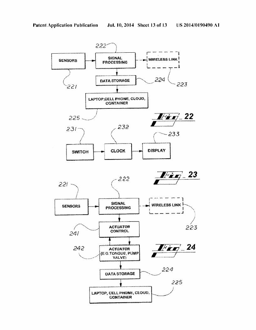
0094 FIG. 18 is an alternative embodiment of oral appli ance 80 comprising electronic components to monitor, Screen and report physiological variables related to sleep apnea and device usage. The electronic components, in one embodi ment, include a LED 181 and accompanying sensor 182, power Supply and electronics compartment 183, sensors 184, and a switch 185. FIG. 18 also illustrates component 5 con taining a medication Source 186 and component 4 to engage the tongue. 0095 FIGS. 19A and B show electronic means sensing change in light transmission. Optical source 190 transmits light across air conduit 8 that is received by an optical sensor 191 that detects the difference in light transmission between light transmitted across clear inhaled air 192 and the dimin ished light transmission across exhaled vapor 193 to deter mine breathing rate within the oral appliance air conduit 8. 0096 FIG. 20 is an illustration of an optical source 200 and detector 201 mounted within a dental tray 1 that also engages the inside Surface of a human or animal lip as part of a system to determine heart rate and or oxygen Saturation. 0097 FIG. 21 is a left sectional view of an anatomical cross-section of a human upper airway (similar to FIG. 1), illustrating a cross-section of appliance 80 positioned in the oral cavity, engaging the upper and lower dentition, and inter acting with the tongue using electronic means 210 to prevent it from obstructing the airway. 0098 FIG. 22 is a relational block diagram of electronic monitoring of usage and diagnostic screening data from oral appliance sensors such as shown in FIG. 18. In one embodi ment sensors 221 are operably coupled to a signal processing device 222, which is operably coupled to a wireless link 223 and data storage 224. The data storage 224 is operably coupled to at least one of a laptop, a cell phone, a cloud, and a container 225. 0099 FIG. 23 is a relational block diagram of alternative embodiment of usage monitoring from interconnection of a clock 232 and display 233 to a switch 231 such as shown in FIG. 18.
0100 FIG. 24 is a relational block diagram of an embodi ment of an electronic actuator control 241 including tongue control, motor, pump, valve, and the like, wherein sensors are operably coupled to a signal processing device 222, which is operably coupled to a wireless link 223 and an actuator con trol. The actuator control is operably coupled to an actuator 242 (e.g. at least one of a tongue, pump, or valve) that is operably coupled to data storage 224. The data storage 224 is operably coupled to at least one of a laptop, a cell phone, a cloud, and a container 225. 0101. In other embodiments of the invention, a tongue restraint is not limited to a passive restraint. In further embodiments, active restraints to the tongue may include electronic, electro-mechanical, and fluidic restraint portions that contact or engage the tongue. In embodiments of the invention, active restraints may be integral of a tongue restraint or operatively coupled to a mechanical restraint to engage a tongue. 0102 Particular embodiments of the present invention have been presented for purposes of illustration and descrip tion, and are not intended to be exhaustive or limited to the invention in the form disclosed. Many modifications and variations will be apparent to those skilled in the art. The preferred embodiment was chosen and described in order to best explain the principles of the invention, the basic and practical application, and to enable others of ordinary skill in
Jul. 10, 2014
the art to understand the invention with various embodiments and various modifications as are Suited to the particular use contemplated. 0103 Having thus described the invention, what is desired to be protected by Letters Patent is presented in the subse quently appended claims. We claim: 1. An oral appliance comprising: an oral cavity engagement device including at least one
tray; a tongue restraint including a tongue contact portion; an element providing a spring force operatively coupled to
the at least one tray and to the tongue restraint, wherein the element providing a spring force is adjustable ante riorly and posteriorly relative to the at least one tray; and
an air conduit disposed in the tongue restraint with a front opening of the air conduit extending beyond an anterior end of the at least one tray and a rear opening of the air conduit at a posterior end of the of the oral cavity engagement device configured to extend to a posterior Surface of a tongue.
2. The oral appliance of claim 1, wherein the element providing a spring force applies a spring force to the tongue restraint.
3. The oral appliance of claim 1, wherein the tongue con tact portion is rigid and angled downward in relation to the at least one tray.
4. The oral appliance of claim 1, wherein the tongue con tact portion includes a slip-resistant surface selected from the group consisting of a Surface including projections, a Surface including bristles, a meshed Surface, a corrugated Surface, an irregular Surface, a porous Surface, a perforated Surface, a grated Surface, a non-slip Surface and an anti-slip Surface.
5. The oral appliance of claim 1, wherein the air conduit includes an airflow control valve.
6. The oral appliance of claim 5, wherein the element providing a spring force applies a spring force to the tongue restraint.
7. The oral appliance of claim 5, wherein the tongue con tact portion is rigid and angled downward in relation to the at least one tray.
8. The oral appliance of claim 1, wherein the at least one tray of the oral cavity engagement device includes an upper tray and a lowertray.
9. The oral appliance of claim 1, wherein the air conduit includes an absorbent material.
10. The oral appliance of claim 2, wherein a spring force applied to the tongue restraint by the element providing a spring force is adjustable.
11. The oral appliance of claim 1, further comprising a sensor disposed in at least one of the oral cavity engagement device and the air conduit.
12. The oral appliance of claim 1, wherein the tongue restraint further includes an actuator.
13. The oral appliance of claim 1, further comprising a light Source disposed in at least one of the oral cavity engagement device and the air conduit.
14. The oral appliance of claim 1, further comprising elec tronics disposed in the oral cavity engagement device.
15. The oral appliance of claim 1, further comprising a strap operatively coupled to the oral cavity engagement device.
16. The oral appliance of claim 1, wherein the element providing a spring force is at least one of a torsion spring, a
US 2014/O 190490 A1
leaf spring, a coiled spring, a compression spring, an exten sion spring, a constant force spring, a wire-form spring, pneu matic spring, a elastomeric spring and a cantilevered spring.
17. The oral appliance of claim 1, wherein the at least one tray is configured to engage at least one of a dentition and an oral tissue.
18. The oral appliance of claim8, wherein the uppertray is adjustably coupled to the lower tray.
19. The oral appliance of claim 18, wherein element pro viding a spring force is operatively coupled to the upper tray and to the tongue restraint
k k k k k
Jul. 10, 2014