us army air defense school fort bliss, texas …sill- defense trends us army air defense school fort...
TRANSCRIPT
US ARMY AIR DEFENSE SCHOOL
Fort Bliss, Texas 79916
September 1970
AIR DEFENSE TRENDS US ARMY AIR DEFENSE SCHOOL
For t Bliss. Texas 79916
IN THIS ISSUE
Page
Cover . . . . . . . . . . . . . . . . . . . . . . . . . . . . . . . . . . . . . . . . . . . . . . . . . . . 1 Air Defense Trends . . . . . . . . . . . . . . . . . . . . . . . . . . . . . . . . . . . . . . . . . . 2
. . . . . . . . . . . . . . . . . . . . . . . . . . . . . . . . . . . . US Army Air Defense School 3 . . . . . . . . . . . . . . . . . . . . . . . . . . US Army Air Defense Center and Fo r t Bliss 3
. . . . . . . . . . . . . . . . . . . 1st Advanced Individual Training Brigade (Air Defense) 4 . . . . . . . . . . . . . . . . . . . . . . . . . . . . . . . . . 6th Artil lery Group (Air Defense) 4
15th Artil lery Group (Air Defense) . . . . . . . . . . . . . . . . . . . . . . . . . . . . . . . . 4 . . . . . . . . . . . . . . . . . . . . . . . . . . . . . . . . . . . . . . . Headquar te rscommand 4
. . . . . . . . . . . . . . . . . . . . . . . . . . . . . . . . . . . . . . . . . . . . Range Command 5 . . . . . . . . . . . . . . . . . . . . . . . . . . . . . . . . . . . . . US Army Air Defense Board 5
. . . . . . . . . . . . . . US Army Combat Developments Command Air Defense Agency 5 US Army Air Defense Human Research Unit. Human Resources
. . . . . . . . . . . . . . . . . . . . . . . . . . . . . . . . . . . . . . . Research Organization 5 . . . . . . . . . . . . . . . . . . . . . . . . . . . . . . . . Air Defense Trends Editorial Staff 6
. . . . . . . . . . . . . . . . . . . . . . . . . . . . . . . . . . . . . . . . . Let te rs to the Editor 7
USAADS INSTRUCTIONAL NOTES Office of Doctrine Development. Literature. and Plans . . . . . . . . . . . . . . . . . . . 11 Nonresident Instruction Department . . . . . . . . . . . . . . . . . . . . . . . . . . . . . . . 14
. . . . . . . . . . . . . NOTES FROM US ARMY AIR DEFENSE CENTER AND FORT BLISS 16
. . . . . . . . . . . . . . . . . . . . . . . . NOTES FROM US ARMY AIR DEFENSE COMMAND 18
NOTES FROM THE US ARMY COMBAT DEVELOPMENTS COMMAND AIRDEFENSEAGENCY . . . . . . . . . . . . . . . . . . . . . . . . . . . . . . . . . . . . . . . . . 22
NOTES FROM THE HUMAN RESOURCES RESEARCH ORGANIZATION . . . . . . . . . . . 24 "
SAFOC . . . . . . . . . . . . . . . . . . . . . . . . . . . . . . . . . . . . . . . . . . . . . . . . . . . 26
HISTORYOFAIRDEFENSE . . . . . . . . . . . . . . . . . . . . . . . . . . . . . . . . . . . . . . . 32
. . . . . . . . . . . . . . . . . . . . . . . . . . . . . . . . . . . . . . . BOLD SHOT/BRIM FIRE 3.70 40
MODERN WEAPONS OF AIR DEFENSE ARTILLERY . . . . . . . . . . . . . . . . . . . . . . . 41
. . . . . . . . . . . . . . . . . . . . . . . . . . . . . . . . THE SOVIET ARMED FORCES TODAY 46
BRITISH RADAR SUCCESS . . . . . . . . . . . . . . . . . . . . . . . . . . . . . . . . . . . . . . . . 55
Page
ANEWLOOKFORCHAPARRALANDREDEYE . . . . . . . . . . . . . . . . . . . . . . . . . . 56 BLOWPIPE . . . . . . . . . . . . . . . . . . . . . . . . . . . . . . . . . . . . . . . . . . . . . . . . . . 60
AEGIS-NAVY'S NIX ON STYX . . . . . . . . . . . . . . . . . . . . . . . . . . . . . . . . . . . . . . 62 TRACER OBSERVATION FOR AIR DEFENSE FIRE CONTROL . . . . . . . . . . . . . . . . 65 THE US ARMY IN SATELLITE COMMUNICATIONS . . . . . . . . . . . . . . . . . . . . . . . . 70 BACKGROUND FACTS RELATED TO NATIONAL DEFENSE . . . . . . . . . . . . . . . . . . 76 AIR DEFENSE CONTROL AND COORDINATION SYSTEM . . . . . . . . . . . . . . . . . . . . 78 FDS-WHONEEDSIT? . . . . . . . . . . . . . . . . . . . . . . . . . . . . . . . . . . . . . . . . . . . 84
ABANDONED NIKE MISSILE BASE BECOMES SCHOOL IN SMALL TOWN . . . . . . . . . 87
LESSONS LEARNED IN VIETNAM Tactical Experiences of Deployed Units . . . . . . . . . . . . . . . . . . . . . . . . . . . . . 88
ELECTRONICTERMS . . . . . . . . . . . . . . . . . . . . . . . . . . . . . . . . . . . . . . . . . . . 90 READER'S CORNER
Current Books and Articles of Military In te res t . . . . . . . . . . . . . . . . . . . . . . . . 91
AIRCRAFTRECOGNITION . . . . . . . . . . . . . . . . . . . . . . . . . . . . . . . . . . . . . . . . 96
Air Defense Trends is an instructional aid of tbe United States Army Air Defense Scbool; it i s published wben sufficient material of an instructional nature can be gatbered.

For without belittling the courage with which men have died, we should no t forget those a c t s of courage wi thwhichmen. . . have lived. The courage of life i s often a l e s s dramatic spectacle than the courage of a final moment; but i t i s no l e s s a magnificent mixture of triumph and tragedy. A man does what he must-in spi te of personal consequences, in spi te of obstacles and dangers and pressures-and that i s the basis of a l l human morality .
-John Fitzgerald Kennedy Profiles in Courage (1956)
iii
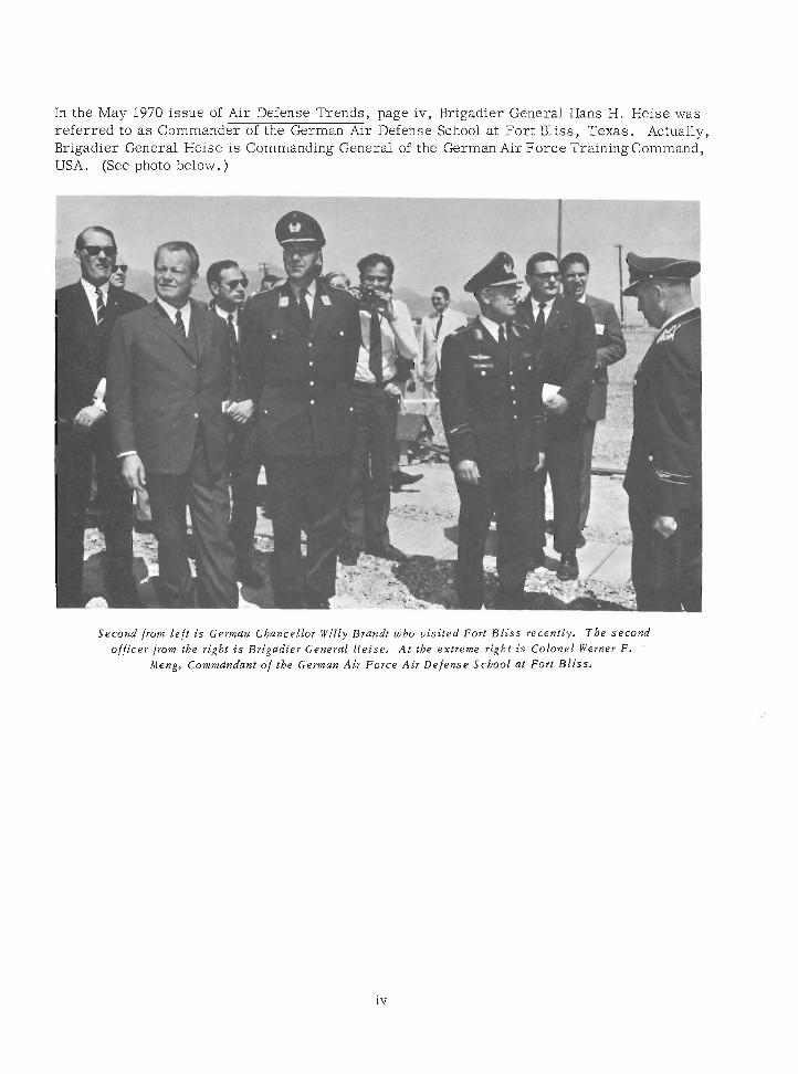
In the May 1970 issue of Air Defense Trends, page iv, Brigadier General Hans H. Heise was referred to as Commander of the German Air Defense School at Fort Bliss, Texas. Actually, Brigadier General Heise is Commanding General of the German Air Force Training Command, USA. (See photo below. )
Second from left i s German Cbancellor Willy Brandt who v is i ted Fort Bl iss recently, The second officer from the right i s Brigadier General Heise, At the extreme right i s Colonel Werner F, .
Meng, Commandant of the German Air Force Air Defense School at Fort Bl iss ,
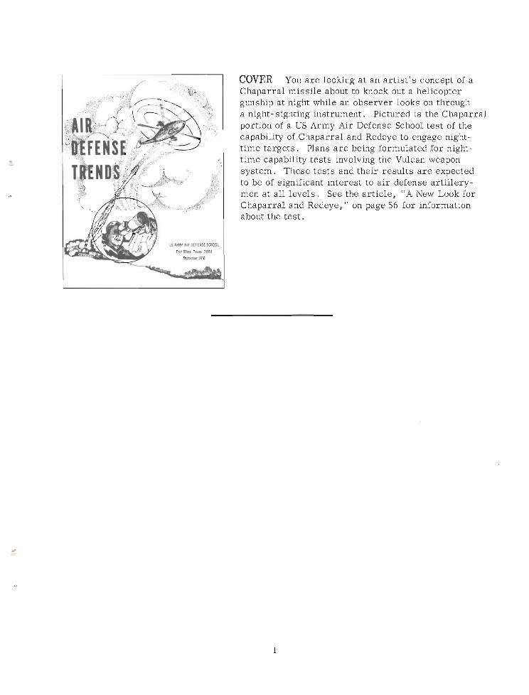
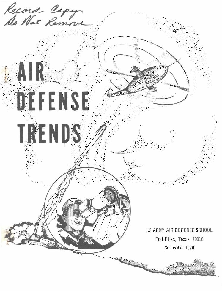
COVER You a r e looking a t an art ist 's concept of a Chaparral missile about to knock out a helicopter gunship at night while an observer looks on through a night- sighting instrument. Pictured is the Chaparral portion of a US Army h r Defense School test of the capability of Chaparral and Redeye to engage night- time targets, Plans a r e being formulated for night- time capability tests involving the Vulcan weapon system. These tests and their results a r e expected to be of significant interest to a i r defense artillery- men at all levels. See the article, "A New Look for Chaparral and Redeye, " on page 56 for information about the test.
AIR DEFENSE TRENDS
An instructional aid of the United States Army Air Defense School, Air Defense Trends is published when sufficient material of an instructional nature can be accumulated. It is designed to keep a i r defense artillerymen informed of unclassified tactical, technical, and doctrinal developments because it is essential to national defense that all levels of a i r defense command be kept aware of these developments and their effect on the a i r defense posture. *
Distribution of this publication will be made only within the School, except for distribu- tion on a gratuitous basis to Army National Guard and USAR schools, Reserve component d
training and ROTC facilities, and a s requested by other service schools, ZI armies, US Army Air Defense Command, Active Army units, major oversea commands, and military assistance advisory groups and missions.
Qualified individuals may purchase copies of Air Defense Trends by writing to The Book Store, US Army Air Defense School, Fort Bliss, Texas 79916.
When appropriate, names and organizations of authors a r e furnished to enable readers to contact authors directly when they have questions concerning an article.
Unless otherwise indicated, material may be reprinted provided credit is given to Air Defense Trends and to the author.
Articles appearing in this publication do not necessarily reflect the opinions of the US Army Air Defense School o r the Department of the Army.
US ARMY AIR DEFENSE SCHOOL
Commandant . . . . . . . . . . . . . . . . . . . . . . . . . . . . . . . . Major General R . T . Cassidy
Assistant Commandant . . . . . . . . . . . . . . . . . . . . . . Brigadier General L. L. Leech, Jr
Deputy Assistant Commandant . . . . . . . . . . . . . . . . . . . . . . . . . Colonel P. A. Loiselle
Secretary . . . . . . . . . . . . . . . . . . . . . . . . . . . . . . . . . . . . . . . . . . Colonel G. Heimer
Office of Doctrine Development, Literature, and Plans . . . . . . . . Colonel M. W. Niemann
School Support Command . . . . . . . . . . . . . . . . . . . . . Lieutenant Colonel T . D. Manross
Director of Instruction . . . . . . . . . . . . . . . . . . . . . . . . . . . . . Colonel J. E. Connor, J r
Command and Staff Department. . . . . . . . . . . . . . . . . . . . . . . . Colonel W. W. Saunders
High Altitude Missile Department . . . . . . . . . . . . . . . . . Lieutenant Colonel L. B. Taylor
. . . . . . . . . . . . . . . . . . . . Low Altitude Air Defense Department Colonel S. C . Buchanan
Missile Electronics and Control Systems Deparment . . . . . . . . . . . . . . . . . . . . . . . . . . . . . . . . . . . . . . . . . .Colonel J. Russo
Nonresident Instruction Department . . . . . . . . . . . . . Lieutenant Colonel W. 0. Gray, J r
US ARMY AIR DEFENSE CENTER AND FORT BLISS
. . . . . . . . . . . . . . . . . . USA Safeguard Central Training Facility Colonel T . Fitzpatrick
Commanding General . . . . . . . . . . . . . . . . . . . . . . . . . . Major General R . T . Cassidy
Deputy Commander. . . . . . . . . . . . . . . . . . . . . . . . . . . . . . . Colonel W. Y . McCachern
Chief of Staff . . . . . . . . . . . . . . . . . . . . . . . . . . . . . . . . . . . . .Colonel W . E . Holmes
1 S T ADVANCED INDIVIDUAL TRAINING BRIGADE (AIR DEFENSE)
. . . . . . . . . . . . . . . . . . . . . . . . . . . . . . . . . . Commanding Officer Colonel W. F. Braun
6 T H ARTILLERY GROUP ( A I R DEFENSE)
Commanding Officer . . . . . . . . . . . . . . . . . . . . . . . . . . Lieutenant Colonel N. E. Trask
1 5 T H ART1 LLERY GROUP (A1 R DEFENSE)
Commanding Officer . . . . . . . . . . . . . . . . . . . . . . . . . . . . . . . . . Colonel J . D. Lewis
HEADQUARTERS COMMAND
Commanding Officer . . . . . . . . . . . . . . . . . . . . . . . . . . . . . . . . . . Colonel B . W: Ford
4
RANGE COMMAND
Commanding Officer . . . . . . . . . . . . . . . . . . . . . . . . . . . . . . . . . . . . :Colonel H. Dews
U S ARMY A I R DEFENSE BOARD
President ......................................... Colonel E. J . Daley
U S ARMY COMBAT DEVELOPMENTS COMMAND A I R DEFENSE AGENCY
Commanding Officer . . . . . . . . . . . . . . . . . . . . . . . . . . . . . . . . Colonel D. T. Chapman
U S ARMY A I R DEFENSE HUMAN RESEARCH U N I T , HUMAN RESOURCES RESEARCH ORGANIZATION
. Chief . . . . . . . . . . . . . . . . . . . . . . . . . . . . . . . . . . . . Lieutenant Colonel F R . Husted
5
A 1 R DEFENSE TRENDS EDITOR1 AL STAFF
Colonel M. W . Niemann . . . . . . . . . . . . . . . . . . . . . . . . . . . . . . . . . Staff Director
Major J . T. Hicks . . . . . . . . . . . . . . . . . . . . . . . . . . . . . . . . . . . . . . . . . . . . Chief
W . E . Sanford . . . . . . . . . . . . . . . . . . . . . . . . . . . . . . . . . . . . . . . . . . . . . Editor
S. 0. Loret te . . . . . . . . . . . . . . . . . . . . . . . . . . . . . . . . . . . . . . . Associate Editor
Major T. G. Green . . . . . . . . . . . . . . . . . . . . . . . . . . . . . . . . . . . Associate Editor
Staff Sergeant A. E . Hartelt . . . . . . . . . . . . . . . . . . . . . . . . . . . . . . . . . I l lustrator
Alice Remmie and Genevieve McPherson . . . . . . . . . . . . . . . . . . . . . . . . . Secre ta r ies

LETTERS
.Enjoyed your historical sketch of the Army Air Defense Command in the January issue of Air Defense Trends. For your information I'd like to bring you up to date on one area that has changed since the article was written. ARADCOM presently has 15 defenses guard- ing major populated and industrial areas. With the inactivation of the Niagara-Malo and Cincinnati- Dayton defenses by 31 March 1970, we will have 13.
Also noted the crest used with the article. Last year the command conducted a contest for a new motto. The selection committee chose "~lirt Above All" to replace "Vigilant and Invincible, " which had been the unofficial motto since 1961. I am enclosing a copy of the ARADCOM embellished crest with the new motto for your use in Trends in the future.
MAJOR JAMES L. MILLER Cbie f, Command Information Division . H Q . ARADCOM
Tbe new crest appears on page 18.
-Ed.
.Without question, CP' Gerald R. Sullivan has well identified the nature and threat of Communist-inspired and Communist- supported "wars of national liberation" in his article, "To Win Popular Support New Direction Is Needed" (Air Defense Trends, January 1970).
Moreover, Captain Sullivan has shown remarkable understanding in regard to the importance of "thinking like the enemy" while developing adequate operational capabilities pursuant to counterguerrilla missions that circumvent the "disturbers" offensive attitude at sublime levels.
History and current Communist Party rhetoric, detailing support of "popular uprisings," substantiate the great concern of those who address the goal of national security through
stability of international boundaries that in turn create an environment conducive to retention of personal freedom for citizens of the third world and nth countries.
Captain Sullivan's position of discouraging anti-American dialogue by individual efforts of confidence was also well received and was adroitly reinforced by comments and historical references to "respect for local populace" and "garnering of popular support of those the Americans chose to defend. "
There is no doubt that the writings of Mao Tse Tung give the strategist a definite insight to the dialectics relative to personal performance demanded of the Communist insurgent.
However, I feel there a r e currently two points of departure from Mao's original theme pertaining to guerrilla warfare, both of operational expedience rather than ideological disenchantment.
First , evolvement of guerrilla action to Phase I11 (which I term "mobile warfare" based on obvious hostility expansion by the superior side in quest of "escalation dominance") is no longer a credible tactic to Communist insurgents because it would merely result in set-piece battle situations that would revert the advantage to the side with the strongest conventional fighting force who is superior a t this level of conflict. General Giap, for example, supports this idea in Vietnam by maintaining that "Democracies cannot fight long or drawn-out wars, so why not leave the conflict level a t the insurgency phase where duration of action can be guaranteed. "
Secondly, Mao's eight points of "courtesy to the host" would soon fade into insignificance if the counterinsurgents merely isolated the battle area to the point where the guerrillas would be contained in a small, constant area: my premise being that these people would soon grow tired of their "guests" if they did not show success, such a s territorial gains.
Additionally, strategists who discuss guerrilla warfare and ensuing postures of counter- action invariably overlook a basic tenet I believe must be considered. That is the use! of own-side guerrillas that change the asymmetrical balance between the forces of the "dis- turber" and the "stabilizer. " Exploitation of the "disturber's" home front debilitates his ability to wage an effective insurgency campaign elsewhere. For example, it would seem that North Vietnam's easiness to deploy guerrillas to the South could be greatly reduced if it had to cope with insurgents a t home.
The difficulty one has, however, in advancing strategy of this type that aids in suppres- sion of external threats to nation states within the United States sphere of influence is that no one is willing to listen to such arguments in light of current political attitudes.
In a world of nuclear plenty, guerrilla warfare, which is a tool in limited war, has become a common occurrence; therefore, if the United States is to remain a s the leader in constraining the insatiable territorial appetite of communism, both strategists and poli- ticians must come to grips with the reality that to win necessitates either dominating the insurgent with overwhelming firepower o r subverting him with his own game in his own backyard.
WILLIAM W . JOHNSON US A m y Aviation Center Fort Rucker, ~ l a b a m a
.In reference to enclosed article from pages 20 and 21 of January 1970 issue of Air Defense Trends, I call your attention to the underlined sentence which is in error . [ ~ d i t o r ' s Note: Refers to comment that the only change to tbe lmproved Hawk pulse acquisition radar was the relocation of the omnidirectional antenna. ]
The article is generalized to the point that little information is given. The Hawk system of the future is of great interest to the present generation of Hawk mechanics who a r e seek- ing new lazowledge and experience. But the small amount of information released may lead one to believe his electronic ability will be stifled by working on the same equipment with which he is already experienced. Improved Hawk is a challenging new system with a definite future. Why not present it a s such?
I'd like to congratulate the editorial staff of this fine publication. Much new, interesting information is always contained here, and many readers look forward to each new issue.
SSG IVAN W . SMITH
The "article" to which you refer was a report in the / o m of a note from the U S Amy Air Defense Board. Notes from various agencies are published to provide our readers with advance information on agency activities. When appropriate, comprehensive reports appear as follow-on articles. In the case of Improved Hawk, some changes have been made which we cannot publish because of security restrictions.
01 understand that TM 38-750 is being revised again. Since my unit hasn't gotten a draft, do you have any idea what impact this revision will have on ADA units' logbooks, both conventional and missile?
Secondly, since TAERS has proved to be quite costly (in man-hours) to the service, what is the chance of getting rid of the system altogether or at least getting it automated so that we can get out of this paper war.
SNOWED UNDER
See synopsis o f changes to TM 38-750, USAADS lnstnrctional Notes, page 1 1 .
-Ed,
.Reference COL Gray's article, "The ADA Advanced Course Graduate-Must Your Professional Development Stop Here?" in the January 1970 issue of Air Defense Trends. Would like to suggest the Air Force equivalent of the Army War College correspondence
- -
course a s an alternate to the hard-to-get-into Army course. The Air Force course is a good one and is open to lieutenant colonels, GS- 13 civilians, and above. They're generous on waivers, and the acceptance rate is very high. Write direct to Commandant, Air War College (AWCAPC), Maxwell Air Force Base, Alabama 36112, for details and enrollment forms (AWC Form 0-6).
JOSEPH B. FRIES, DAC USACDCADA
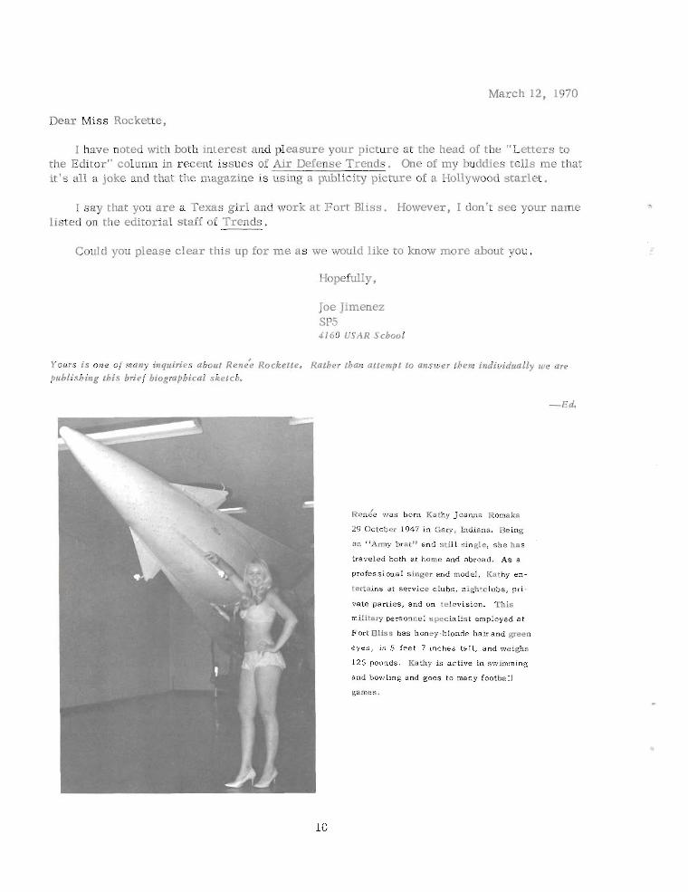
March 12, 1970
Dear Miss Rockette,
I have noted with both interest and pleasure your picture at the head of the "Letters to the Editor" column in recent issues of Air Defense Trends. One of my buddies tells me that it's all a joke and that the magazine is using a publicity picture of a Hollywood starlet.
I say that you a r e a Texas girl and work at Fort Bliss. However, I don't see your name listed on the editorial staff of Trends.
Could you please clear this up for me a s we would like to know more about you.
Joe Jimenez SP5 4160 USAR School
Yours i s one of many inquiries about ~ e n e ; Rockette. Rather tban attempt to answer them individually we are publishing this brief biogmpbical sketch.
~ e n e ' e was born Kathy Joanna Romeka
29 October 1947 i n Gary, Indiana. Being
an "Army brat" and st i l l single, she has .
traveled both a t home and abroad. As a
professional singer and model, Kathy en-
tertains a t service clubs, nightclubs, pri-
vate parties, and on television. This
military personnel specialist employed a t
Fort Bliss has honey-blonde hairand green
eyes, is 5 feet 7 inches tall, and weighs
125 pounds. Kathy ia active in swimming
and b o w h g and goes to many football
games.
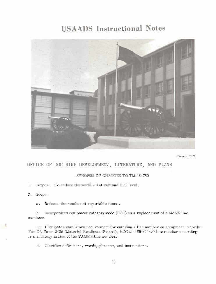
USAADS Instructional Notes
Hinnun Hall
OFFICE OF DOCTRINE DEVELOPMENT, LITERATURE, AND PLANS
SYNOPSIS'OF CHANGES TO TM 38-750
1. Purpose: To reduce the workload a t unit and DPU level.
2. Scope:
a . Reduces the number of reportable items.
b. Incorporates equipment category code (ECC) a s a replacement of TAMMS line numbers.
c . Eliminates mandatory requirement for entering a line number on equipment records. For DA Form 2406 (Materiel Readiness Report), ECC and SB 700-20 line number recording is mandatory in lieu of the TAMMS line number.
d. Clarifies definitions, words, phrases, and instructions.
e . Updates illustrations.
f . Reduces reportable organizational maintenance actions.
g. Reduces number of failure codes, calibration codes, and source codes.
3. Form changes: The following forms have been revised:
a . DA Label 80, 1 January 19M, is replaced by revised DA Label 80 (US Army Calibration System), 1 January 1970.
b. DA Form 2408, 1 May 1967, is replaced by revised DA Form 2408 (Equipment Log Assembly), 1 January 1970, which provides an order of precedence for status symbols.
c . DA Form 2416, 1 January 1964, i s replaced by revised DA Form 2416 (Calibration Data Card), 1 January 1970.
d. DA Form 2417, 1 January 1964, i s replaced by revised DA Form 2417 (Unserviceable o r Limited Use Tag), 1 January 1970.
4. Procedural changes:
a . DD Form 314 (Preventive Maintenance Schedule and Record). A procedure for use of this form to record NORS/NORM (nonoperational for supplies/maintenance) nonavailable time has been added.
b. DA Form 2404 (Equipment Inspection and Maintenance Worksheet). Transcribing of completed maintenance action to another form is eliminated unless the action i s a reportable organizational maintenance action or a higher level maintenance action i s required.
c . DA Form 2406 (Materiel Readiness Report). New cutoff and submission dates have been established to coincide with unit readiness reports (AR 220- 1). NORS/NORM data,
'
required for materiel readiness reporting, a r e provided units by support elements on DA Form 2407 and/or DA Form 2418 (Backlog Status and Workload Accounting Card).
d . DA Forms 2407 and 2407- 1 (Maintenance Request and Continuation Sheet). These forms a r e now also used to report organizational maintenance actions and warranty claim actions.
e . DA Form 2408- 1 (Equipment Daily o r Monthly Log). Options for the use of this form a r e now permitted.
f . DA Form 2408-7 (Equipment Transfer Report). An additional use for this form has - been prescribed; i . e . , to report periodic usage of selected items of equipment.
g . Revised list of equipment. The list of equipment on which historical records a r e . maintained has been revised, and the items of equipment a r e identified in ECC/line number sequence.
h. Chapter 6. This chapter has been completely revised. All calibration data will be sent direct to US Army Metrology and Calibration Center, Redstone Arsenal, Alabama.
5. Appendix changes:
a . Appendix A. The number of failures and calibration codes has been reduced. Only one parts source is retained. Table 20, Equipment Category Codes (ECC), has been added.
b. Appendix B. This appendix has been completely revised to identify mailing addresses to the appropriate ECC/line number.
c . Appendix C. A reduction is made in the number of items of equipment fo r which maintenance information is to be sent to the national level. Some new items have been added and al l have been identified by ECC. Specific items a r e identified for which usage informa- tion is to be reported.
d. Appendix D. This appendix has been updated to identify equipment by ECC .
e. Appendix E. The list of items for serial number density data collection has been updated, and items of equipment a r e listed in ECC sequence. (A line number continues to apply for commercial vehicles. )
BATTERY TERMINAL EQUIPMENT (BTE) INSTRUCTION
Evidently not al l personnel in the field a r e aware that the US Army Air Defense School offers instruction on the AN/GSA- 77 (BTE). All graduates of 24P20 and 24F20 maintenance courses receive 48 hours of instruction on operation and maintenance of the BTE,
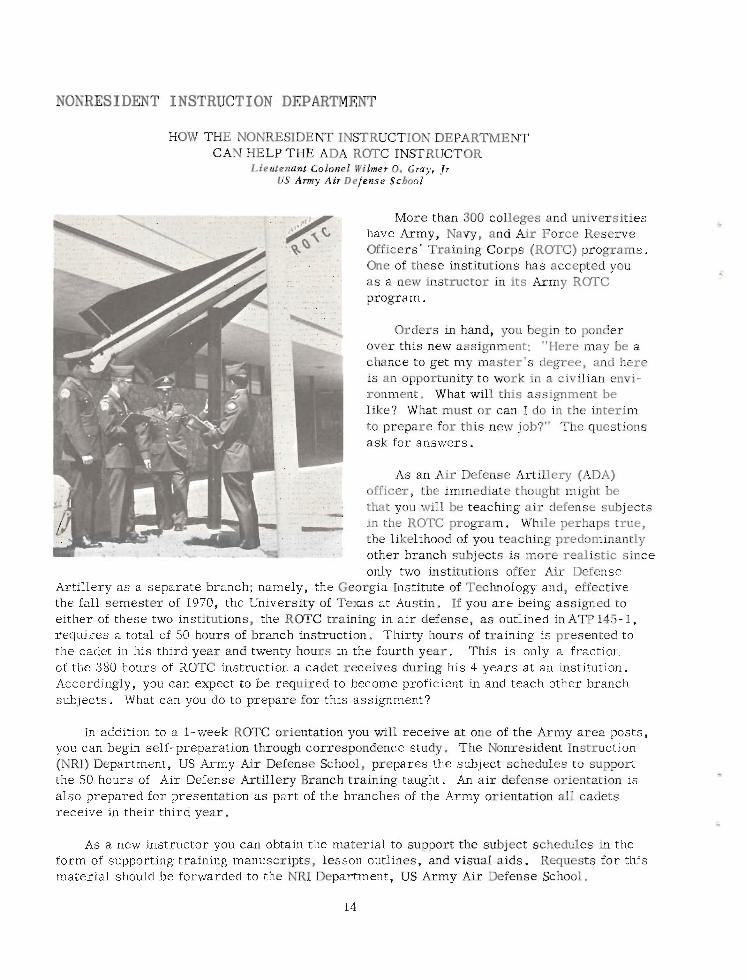
NONRESIDENT INSTRUCTION DEPARTMENT
HOW THE NONRESIDENT INSTRUCTION DEPARTMENT CAN HELP THE ADA ROTC INSTRUCTOR
Lieutenant Colonel Wilmr 0. Gray, Jr U S A m y Air Defense Scbool
More than 300 colleges and universities have Army, Navy, and Air Force Reserve Officers' Training Corps (ROTC) programs. One of these institutions has accepted you a s a new instructor in its Army ROTC program.
Orders in hand, you begin to ponder over this new assignment: "Here may be a chance to get my master's degree, and here is an opportunity to work in a civilian envi- ronment. What will this assignment be like? What must o r can I do in the interim to prepare for this new job?" The questions ask for answers.
As an Air Defense Artillery (ADA) officer, the immediate thought might be that you d l be teaching air defense subjects in the ROTC program. While perhaps true, the likelihood of you teaching predominantly other branch subjects is more realistic since only two institutions offer Air Defense
Artillery as a separate branch; namely, the Georgia Institute of Technology and, effective the fall semester of 1970, the University of Texas at Austin. If you a r e being assigned to either of these two institutions, the ROTC training in a i r defense, a s outlined in ATP 145- 1, requires a total of 50 hours of branch instruction. Thirty hours of training is presented to the cadet in his third year and twenty hours in the fourth year. This is only a fraction of the 380 hours of ROTC instruction a cadet receives during his 4 years at an institution. Accordingly, you can expect to be required to become proficient in and teach other branch subjects. What can you do to prepare for this assignment?
In addition to a 1-week ROTC orientation you will receive at one of the Army area posts, you can begin self-preparation through correspondence study. The Nonresident Instruction (NRI) Department, US Army Air Defense School, prepares the subject schedules to support the 50 hours of Air Defense Artillery Branch training taught. An air defense orientation is also prepared for presentation a s part of the branches of the Army orientation all cadets receive in their third year.
As a new instructor you can obtain the material to support the subject schedules in the form of supporting training manuscripts, lesson outlines, and visual aids. Requests for this material should be forwarded to the NRI Department, US Army Air Defense School.
Beginning with the school year 1970-71, the Air Defense School will send an a i r defense brochure to all colleges and universities with an Army ROTC program. This brochure is intended to assist the graduating cadet in his selection of a career branch. It will contain a brief history of a i r defense, the history of the US Army Air Defense School, and a typical career pattern for an Air Defense Artillery officer a s well a s highlights concerning the Fort Bliss-El Paso area. This brochure should prove helpful to you a s an a i r defense instruc- tor in selling the Air Defense Artillery Branch and in answering questions about a i r defense and the type of career an Air Defense Artillery officer pursues.
Air defense periodic publications that will help keep you abreast of a i r defense technology a r e also available. These publications a r e the Air Defense Trends, the Air Defense Digest, and a i r defense special texts. They a r e yours for the asking.
To prepare yourself for instruction in other than branch subjects, enroll in the corre- spondence course program of the Air Defense School. Correspondence courses a r e available in drill and command, map reading, military leadership, and infantry battalion and brigade organization and operations.
If the desired correspondence courses a r e not available through the NRI Department, US Army Air Defense School, you may enroll in the correspondence course program of the Army school offering the required course o r courses.
For the graduating ROTC cadets who have been notified of their assignment to ADA, the NRI Department offers a preparatory correspondence course. This course i s intended to prepare the cadet for the a i r defense artillery basic course he will attend when he enters active duty. The course covers map reading, an introduction to a i r defense systems, and organizational maintenance and maintenance management. Cadets may enroll individually o r a s a group under the group study procedure.
In addition to the academic instruction at the institution, you may be required to perform duty involving the sponsorship of an ROTC fraternal organization, coaching a drill o r rifle team, and participating in weekly drills and summer camp training. The challenges a r e many. Your success will depend on how well you prepare fo r the job before you arr ive at the institution and how you pursue your tasks after arrival .
Details and assistance can be provided by writing to:
Commandant US Army Air Defense School ATI'N NRI Department P. 0. Box 5330 Fort Bliss, Texas 79916
LET US HEAR FROM YOU!
In the next issue of Air Defense Trends, the Nonresident Instruction Department closes this ser ies of articles with "How the Nonresident Instruction Department Can Assist the ADA Officer in His M U G Assignment."
The author wishes to acknowledge the assistance of Colonel Herbert A. Smith, Professor of Military Science, University of Texas at El Paso, and his staff for their help in the preparalion of this article.
Notes From US Army Air Defense Center and Fort Bliss
FORMAL EDUCATION FOR CAREER OFFICERS
Undergraduate Program
A new Officer Undergraduate Degree Program (OUDP) provides young career officers an opportunity to earn a baccalaureate degree at an accredited college or university of their choice while drawing pay and allowances for active duty. Selections a re made by the career branches of the Officer Personnel Directorate, with military performance and service poten- tial a s primary factors. Basic eligibility criteria for acceptance a r e
.The officer must bea Reservist in a Voluntary Indefinite category and have Regular Army potential or be a member of the Regular Army. He must have completed not less than 2 years and not more than 7 years of commissioned service.
.The degree pursued must be attainable within a period of 2 years o r less and be related to duties to be performed in the officer's career branch.
.He must agree to accept 2 years of active duty for each year of schooling or fraction thereof, but not less than 3 years.
The Army will provide full tuition support and will reimburse the student for textbooks and supplies up to $100 per fiscal year. Any eligible officer may request consideration by writing to his branch. This new educational opportunity does not affect the Degree Comple- tion Program (Bootstrap), which makes any officer needing a year o r less for his baccalau- reate degree eligible for up to 12 months' full-time college attendance under the provisions of AR 621-5. Detailed instructions a r e contained in DA Circular 351-5, 27 January 1970.
Graduate Program
Qualified Regular Army or Voluntary Indefinite category officers and warrant officers may apply for long course training leading to a master's degree and, in exceptional cases, to a doctorate. The schooling will normally be limited to 2 years. Acceptance is contingent upon certain eligibility factors:
.Prior service must not exceed 19 years of promotion list service for Regular Army officers or 15 years of active Federal service for Reserve component officers at the time schooling begins.
.A security clearance for access to classified information to include SECRET is a minimum requirement.
.The individual's academic record must show a capacity for advanced education, and his military service should show a natural tendency toward service in the discipline for which he is to receive training.
Individuals must apply specifically for the training involved or submit a statement that they desire and accept detail to such training. To apply, submit DAForm 1618-R, Application for Detail a s Student Officer a t a Civilian Educational Institution, in duplicate and forward through the first field grade officer in your chain of command. Detailed instructions a r e con- contained in chapter 4, AR 350- 200.
C HAPARRAL/ W L C AN UNITS INC RE ASING
Eight Chaparral/Vulcan battalions have been activated a t the US Army Air Defense Center. Some a r e still in training; others have completed training and have been deployed. Here is a list of units and their locations:
5th Battalion, 67th Artillery - USAADS support at Fort Bliss, Texas. 6th Battalion, 67th Artillery - Fort Riley, Kansas. 4th Battalion, 61st Artillery - Fort Carson, Colorado. 1st Battalion, 59th Artillery - Germany. 7th Battalion, 67th Artillery - Germany. 7th Battalion, 61st Artillery - in training a t Fort Bliss, Texas. 2d Battalion, 60th Artillery - in training a t Fort Bliss, Texas. 3d Battalion, 61st Artillery - in training a t Fort Bliss, Texas.
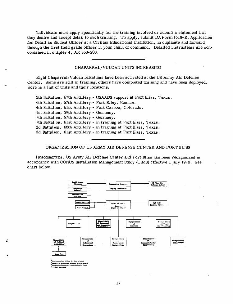
ORGANIZATION OF US ARMY AIR DEFENSE CENTER AND FORT BLISS
Headquarters, US Army Air Defense Center and Fort Bliss has been reorganized in accordance with CONUS Installation Management Study (CIMS) effective 1 July 1970. See chart below.
U.t. OffI.2. a t loco Il,.t- w f i c .
Vl. L~YU Ch1.f of Staff
Notes From
Air Defense
ARADC OM COMMUNICATIONS
US Army
Command
". . . although Congress can make a general, it takes communications to make him a commander. " *
This statement is particularly true within the United States Army Air Defense Command (ARADCOM), for its major subordinate commands a r e spread from coast to coast within the continental United States. When reaction times to launch missiles in defense of major indus- tr ial and population centers a r e measured in seconds, extremely reliable command and control voice and record communications circuits a r e paramount.
In October 1967, in accordance with an agreement signed by CG, ARADCOM, and CG, United States Army Strategic Communications Command (USASTRATCOM), the USASTRATCOM Signal Group (AD) was formed at Ent Air Force Base, Colorado, to fulfill the mission of providing all communications support to ARADCOM. To perform this mis- sion, the organization shown in figure 1 was developed. The USASTRATCOM commander a t each level performs the "dual-hatted function of commander and signal officer. Although this double function may seem unique, we have had the same sort of arrangement since the mid- 1950's where, within a division, the division signal officer is also the commander of the signal battalion. Experience has shown that by this arrangement the organization is capable of providing maximum responsiveness.
The heart of the a i r defense mission res ts a t the defense and battery levels; consequently, these a r e the levels at which the ARADCOM communications network is the most intense. Basically, two types of communications networks support the defenses; however, in most cases the source of communications circuits is a local telephone company, responsive to military requirements and abundant with experience and expertise.
In a defense supported by a peripheral microwave system, the type of its configuration would be a s shown in figure 2. At present, peripheral microwave systems a r e extensively used in support of the Pittsburgh, Chicago, Los Angeles, San Francisco, and Homestead- Miami defenses. These microwave systems exceed 99 percent in reliability and have a self-healing capability of restoring the circumferential path when a break occurs in the ring.
I
*General Omar N. Bradley, A Soldier's Story.
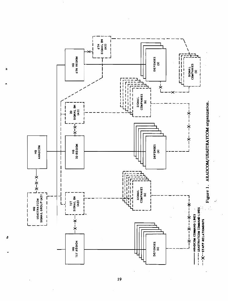
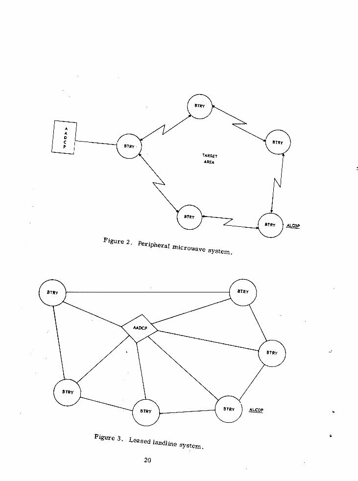
Figure 2 . Peripheral microwave system.
Figure 3 . Leased landline system.
20
To improve the reliability of communications within the aforementioned defenses, leased commercial landlines (wire circuits) a r e available for backup. Programing actions have been initiated by Headquarters, ARADCOM, and Headquarters, USASTRATCOM Signal Group (AD), to provide peripheral microwave systems for the remainder of the ARADCOM defenses prior to F Y 72.
At nonmicrowave defenses, the required voice and data circuits a r e furnished solely by leased commercial landlines. In this instance, the configuration resembles a spoke and ring from the Army a i r defense command post (AADCP) to each of the firing batteries and in a ring between batteries (fig 3). The backup for this type of configuration is a commercial VHF radio system, also in a spoke configuration.
Additionally, terminated at each AADCP and fire unit a r e commercial telephone circuits and tielines to CONUS army switching facilities. These a r e used primarily for administrative traffic.
The provision and administration of these communications paths a r e not the only concern of the USASTRATCOM Signal Group (AD), for the operation and maintenance of switching exchanges and communications centers in which the multitude of these circuits terminate a r e their concern also. Such an intense configuration of networks requires management "par excellence" in order that the required degree of communications reliability is provided throughout ARADCOM. Personnel of USASTRATCOM Signal Group (AD) a r e dedicated to this mission.
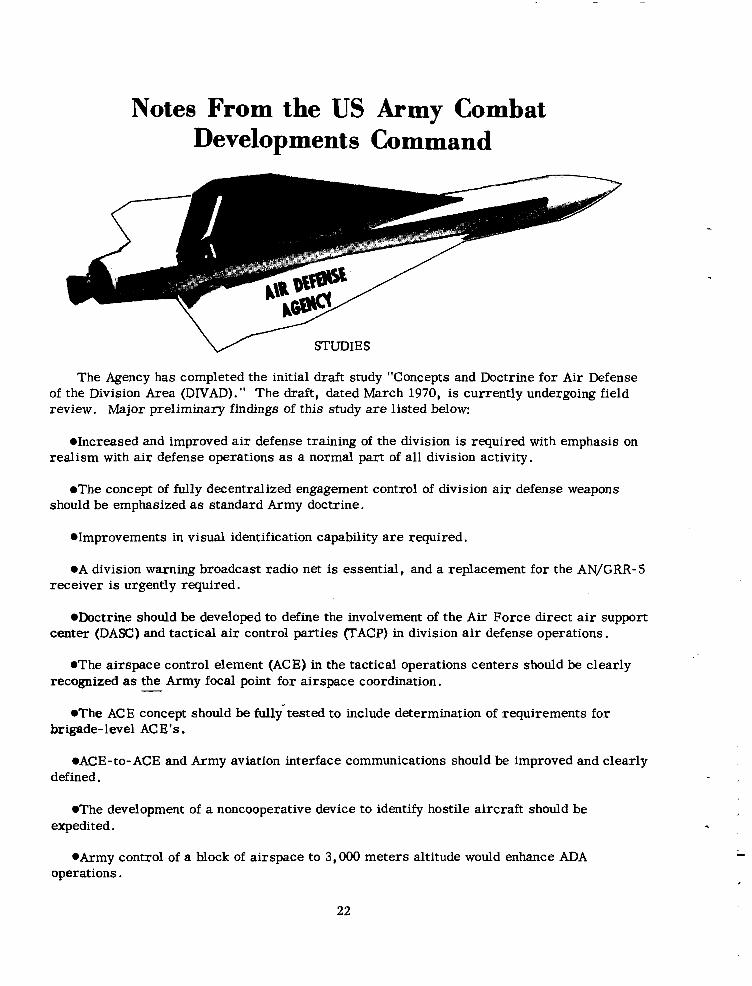
Notes From the US Army Combat Developments Command
'L' STUDIES
The Agency has completed the initial draft study "Concepts and Doctrine for Air Defense of the Division Area (DIVAD)." The draft, dated March 1970, is currently undergoing field review. Major preliminary findings of this study a r e listed below:
.Increased and improved a i r defense training of the division is required with emphasis on realism with a i r defense operations a s a normal part of all division activity.
.The concept of fully decentralized engagement control of division a i r defense weapons should be emphasized a s standard Army doctrine.
.Improvements in visual identification capability a r e required.
.A division warning broadcast radio net i s essential, and a replacement for the AN/GRR- 5 receiver is urgently required.
.Doctrine should be developed to define the involvement of the Air Force direct a i r support center (DASC) and tactical a i r control parties FACP) in division a i r defense operations.
.The airspace control element (ACE) in the tactical operations centers should be clearly recognized as the Army focal point for airspace coordination. -
.The ACE concept should be fullytested to include determination of requirements for brigade-level ACE'S.
.ACE-to- ACE and Army aviation interface communications should be improved and clearly defined.
.The development of a noncooperative device to identify hostile aircraft should be expedited.
.Army control of a block of airspace to 3,000 meters altitude would enhance ADA operations.
*A substitute for the forward area alerting radar ( F U R ) should be provided until F U R is fielded.
.Planned weapon improvements should be expedited.
The Agency recently published the coordination draft of phase I of the SAM- D Firing Doctrine Analysis Study (FIDOC). The phase I study is designed to provide US Army Missile Command and the SAM- D prime contractor (Raytheon) an overall view of the operational con- siderations pertaining to the automation of the SAM- D engagement sequence and fire control means. The study develops a trial firing doctrine for SAM- D in general terms of engagement functions, engagement control, and man/machine relationships and will influence design of the SAM- D system automatic data processing equipment.
INTERNATIONAL STANDARDIZATION
The Agency will serve a s the custodian for the Quadripartite (Great Britain, Canada, Australia, and Unitedstates) Glossary of Air Defense Terms and will revise and republish the glossary as necessary. The Quadripartite Glossary will include those a i r defense terms from the US Army Dictionary of Terms that a re of interest to two o r more of the Quadripartite nations.
FIELD MANUALS
The new FM 44- 1, US Army Air Defense Artillery Employment, has been printed and distributed. The new manual, dated February 1970, supersedes the July 1967 issue of FM 44-1.
Notes From the Human Resources Research Organization
1. The following technical reports (TR) produced by HUMRRO Division No. 5, Fort Bliss, Texas, have recently been published:
a . TR 69-22, Determination of Ground-to-Aircraft Distance by Visual Techniques.
(1) Two visual techniques for use in measuring true ground-to-aircraft distances were examined for accuracy a s part of research to develop methods for training forward area a i r defense gunners to estimate range to aircraft. During the test, information was also obtained on how accurately aircraft fly, desired flight profiles during training o r test- ing, and on the accuracy of the two sighting methods as measured by radar and photographic data.
(2) It was found that the flyover method, in which range assistants were along the ground projection of the flightpath, generally produced a smaller amount of e r r o r than the range sight method, in which the assistants were located some distance from the flightpath. However, the latter technique was more efficient because fewer personnel were needed for its operation.
(3) This report should be of interest to those concerned with range estimation train- ing for a i r defense application and with distance estimation using sighting methods.
b. TR 69-25, Development of a Procedure-Oriented Training Program for Hawk Radar Mechanics.
(1) This report describes the development of a 24-week program (normally 29 weeks) for training Hawk continuous-wave radar mechanics. The program was dev.eloped to reduce failure rates in training without loss in job proficiency in graduates.
(2) The course was based on functional context and procedure-oriented training concepts. Complete detailed procedures for troubleshooting were developed and specified in manuals; associated instruction, including training aids and texts for teaching the pro- cedures, was developed. Three classes given the experimental training showed failure levels generally lower than conventional classes, and end-of-course proficiency of graduates was equal to o r slightly superior to that of graduates from conventional classes. A followup questionnaire on job performance in the field a year after training did not show any difference in job performance capability between experimental and conventional course graduates.
(3) The US Army Air Defense School i s currently conducting a 13-week course for first enlistment mechanics (MOS 23R20) that is based on the results of this research and makes extensive use of the training aids and texts developed for the experimental course. In addition, the US Army Materiel Command has concurred in a proposal by the School to include symptom-collection procedures developed in the research in Department of the Army technical manuals; making these procedures available in official manuals removes the time- consuming training requirement for students to memorize them.
(4) This repor t should be of interest to those concerned with t he functional context and procedure-oriented methods of training, especially in the i r application t o training fo r troubleshooting and electronics maintenance.
2 . Several draf t technical repor t s have been prepared by HUMRRO Division No. 5 and a r e awaiting approval by Department of t he Army. These repor t s include:
a . Studies on Reduced- Scale Ranging Training With a Simple Range F inder .
b. Methods of Training f o r the Engagement of Aircraft With Small Arms .
c . Aircraf t Recognition Performance of C rew Chiefs With and Without Forward Observers .
d . Auditory and Visual Tracking of a Moving Targe t .
3 . Military r e sea r ch presently being conducted by HUMRRO a t Fo r t Bliss is concernedwith:
a . Training Methods fo r Forward Area Air Defense Weapons (Work Unit SKYFIRE).
b . Evaluating Concepts f o r Aircraft Recognition Training (Work Unit STAR).
c . Determination of Performance Capabilities and Training Requirements fo r Manual Command and Control Functions of the Safeguard Weapon System (Work Unit MANICON).
d . Curr iculum and Instructional Improvements f o r the Air Defense Artil lery Officer Advanced Course (Work Unit SKYGUARD).
e. Identifying Fac tors Which Influence the Discrimination of Visual Patterns (Basic Research 16).
4 . Work Unit STAR will be completed during F Y 70. All other cur ren t p rograms will be continued in addition t o the following programs proposed f o r FY 71:
a . Training US Army Security Agency Operators (Exploratory Research 81).
b . Low-Cost Simulation in Military Training (Exploratory Research 82).
c . General Educational Development Program for the Army (Exploratory Research 83).
SAFOC Major General Jobn L. Klingenbagen
Director of Army Aviation OACSPOR. DA
Editor's Note:
This article fitst appeared in the 30 November 1969 issue of Anny Aviation. Tbe author has since been assigned a s Commanding General, US Anny Aviation Systems Command, St. Louis, Missouri. Air Defense Trends does not authorize republication of tbis article, eitber in wbole or in part.
A NEW SUBJECT
In the last few newsletters I have included information on aviation subjects which don't receive much publicity but which a r e of interest to all aviators. Last month's subject was
"Life Support Equipment" ; this month it's "Air Traffic Control"; specifically, "SAFOC (Semiautomatic Flight Operations Center)" (fig 1) and its contribution to automated a i r traffic regulation.
During the past few years the density of Army aircraft operations has increased many fold, particularly in division tactical areas of operation. The preponderance of new aircraft is rotary wing.
As always, one must pay a price for attaining the high degree of mobility o r freedom to move which rotary-wing air- craft provide. The price which the Army commander must pay is a greatly increased a i r traffic control problem and the need to consider weather and visibility in his opera-
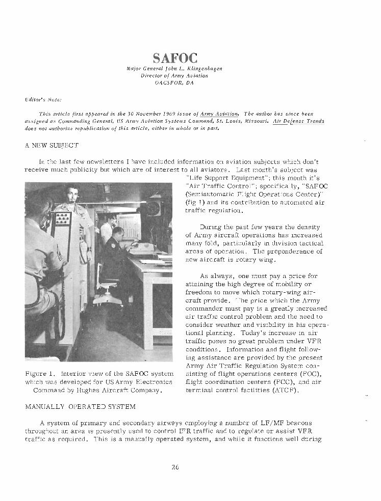
Army Air Traffic Regulation System con- Figure 1. Interior view of the SAFOC system sisting of flight operations centers (FOC), which was developed for USArmy Electronics flight coordination centers (FCC), and air
Command by Hughes Aircraft Company. terminal control facilities (ATCF) . MANUALLY OPERATED SYSTEM
A system of primary and secondary airways employing a number of LF/MF beacons throughout an area is presently used to control IFR traffic and to regulate o r assist VFR traffic a s required. This is a manually operated system, and while it functions well during
VFR conditions, the system can quickly become saturated during IFR periods, thereby limiting the versatility, responsiveness, and effectiveness of airmobile operations.
Densities a s high a s 300 aircraft can be expected in a division area under the control of one FOC during an airmobile operation. An a i r traffic controller in a manual FOC can con- trol only 6- 12 aircraft. These aircraft must have a high degree of freedom to fly without the necessity for time-consuming flight plan filing, they must be able to fly at very low attitudes, and they must be able to operate in spite of reduced visibility. Since many of these aircraft a r e relatively small, there a r e severe limitations on the weight and size of avionics equip- ment which can be carried.
AUTOMATION VITAL
Terminal area control problems a r e heightened by the convergence of landing and depart- ing traffic. Here, the controller workload increases. It has become evident that a consider- able amount of automatic assistance is required to permit a i r traffic controllers to cope with present and anticipated aircraft densities during periods of reduced visibility.
As a f irst step, the Army analyzed the entire a i r traffic control and regulation problem in an extensive study titled, "The Army Tactical Air Space Regulation System" (ATARS). This study identified the essential elements of such a system with special emphasis on the need to develop an automated flight operations center. To identify the a i r traffic regulatory functions that can be automated and the problems associated therewith, an R&Dprogram titled "SAFOC" was initiated. It was decided that a semiautomatic flight operations center (SAFOC) could be fabricated to test the feasibility and military potential of such a concept by procur- ing a modified AN/TSQ-51 f i re direction center.
In the design concept, the SAFOC was envisioned to ultimately replace the existing man- ual FOC's and FCC's. The military potential test was designed along those lines, but is now being expanded to demonstrate automation of terminal control facilities. One basic SAFOC (advanced development feasibility type) was delivered to the Army in September of this year and testing is now underway.
Although designed primarily for rotary-wing aircraft use, the SAFOC will be capable of controlling flights of higher performance fixed-wing aircraft a s well a s a mix of different aircraft types.
The SAFOC will have the capability of performing en route traffic regulations for about 100 flights. A much greater number (from 300-600) of aircraft can be handled where forma- tion flying is employed, since a formation is treated a s one flight. . SAFOC DESIGN APPROACH
The approach taken in the design of the SAFOC was based upon the fact that the low- performance aircraft which a r e to be controlled can operate efficiently at low altitude and, in fact, will often operate a s low a s possible to avoid enemy detection. At these low altitudes conventional radar and secondary radar methods for obtaining position information on aircraft a r e of little value.
However, real-time positioning information is required; therefore, the primary means for keeping track of aircraft will be by automatic position reports over an HF data link from each aircraft 's navigation equipment and altimeter. The computer will ask for reports on a roll call basis with the reports occurring at the rate of two aircraft per second so that 100 aircraft can be polled in 50 seconds. The SAFCC will also employ conventional radar and secondary radar for keeping track of the higher performance aircraft which will generally be flying above the radar horizon.
The position data which a r e obtained by the means described above will be entered into a eta processing subsytem where it can be operated upon automatically by the computer to determine the possibility of conflicts. In such cases, the data processor will determine the necessary maneuvers to be taken to avoid the conflict and indicate to the a i r traffic controller by means of an electronic display the action he should take.
SAFCC FUNCTIONS
A list of the 12 functions performed by SAFOC is a s follows:
1. Process flight plans, either prior to or during flight. The Army aviator, if unable to file a flight plan prior to takeoff, will file with the controller after takeoff. The controller will then enter the flight plan into the system. The computer will e r r o r check every flight plan.
2. Compute present position of each aircraft and direction of flight from the data which will come in by an air-to-ground data link.
3 . Compute, based upon position and direction data, a safe volume of airspace sur- rounding each aircraft. This airspace will define the limits around each aircraft which, if crossed, will create a conflict with another aircraft.
4. Periodically (every 10-20 seconds) check for conflicts which may result in collisions.
5. When potential conflicts a r e detected, compute necessary flightpath changes to avoid the conflict.
6. Automatically trigger a warning signal to the controller when a conflict is detected.
7 . Compute route ETA'S and handoff times and automatically display and transmit this information to adjacent FOC's o r terminals.
8. Determine traffic flow restrictions and alert the controller to unsafe traffic flow o r traffic density situations.
9 . Store and display upon demand a variety of input data such a s meteorological infor- mation, maps, a i r corridors, and restricted airspace information.
10. Provide an automated tracking capability by using either data link o r radar inputs.
11. Store for display upon demand all aircraft tracks. Friendly aircraft track data and flight plan data will be automatically transmitted to a i r defense centers upon demand. Hostile flights will be automatically received from a i r defense centers and warning signals thus gen- erated to alert the controller so that friendly aircraft can be warned.
12. Determine when each aircraft should transmit its present position. The SAFOC concept as it i s now being evolved consists of several elements which would not necessarily be separately identified in the ultimate system. However, to better illustrate the functioning of the concept, the associated subsystems a r e enumerated briefly here.
AIRBORNE SUBSYSTEM
They include an airborne subsystem which consists of the onboard navigation equipment which determines aircraft position and displays it to the pilot, a data link which encodes the position in digital form, an airborne transceiver which i s used to transmit the information to the SAFOC, and a standard IFF beacon transponder which will respond to a ground-based interrogator in the normal fashion a s used with other a i r defense o r military a i r traffic reg- ulation systems. (One of the unique features of the SAFOC i s that it will be able to obtain information and identify aircraft by either the airborne data link subsystem o r the beacon.)
GROUND COMMUNICATIONS
Also, a ground communications subsystem with the following radio communications capa- bilities: three channels of UHF-AM o r VHF-AM, three channels of VHF-FM and four of high frequency single sideband, a receiver for monitoring the a i r warning net, and two radiotele- type sets for exchange of traffic information in two nets.
There's a data processing subsystem to provide a high degree of flexibility in the a rea of message processing which consists of the following components: a high-speed digital com- puter, computer peripheral equipment, and data link buffers. The computer, a high-speed, general-purpose digital computer, will communicate either directly o r indirectly with all parts of the SAFOC system and have the necessary data processing speed and'storage,capac- ity for performing the system functions.
DISPLAY SUBSYSTEM
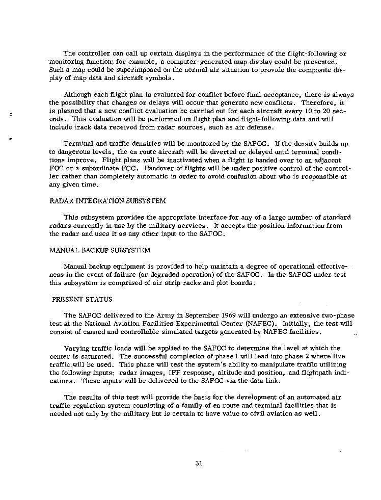
Additionally, there 's a display subsystem (fig 2) which acts a s the complete interface between the computer and the controllers. Its operations a r e unique, and I'd like to dwell on them for a moment.
For example, all operator decisions and data requests a r e processed through the display buffer and passed on to the computer (fig 3). Area maps, which a r e stored in digital form in the computer memory, can also be displayed on the consoles, individually selected o r dis- played in combination.
With this subsystem, the a i r traffic controller monitors designed flight-following data displayed on a plan position indicator (PPI) scope, continuously monitoring those flights for which he i s responsible and carrying out the pilot alerting function a s necessary.
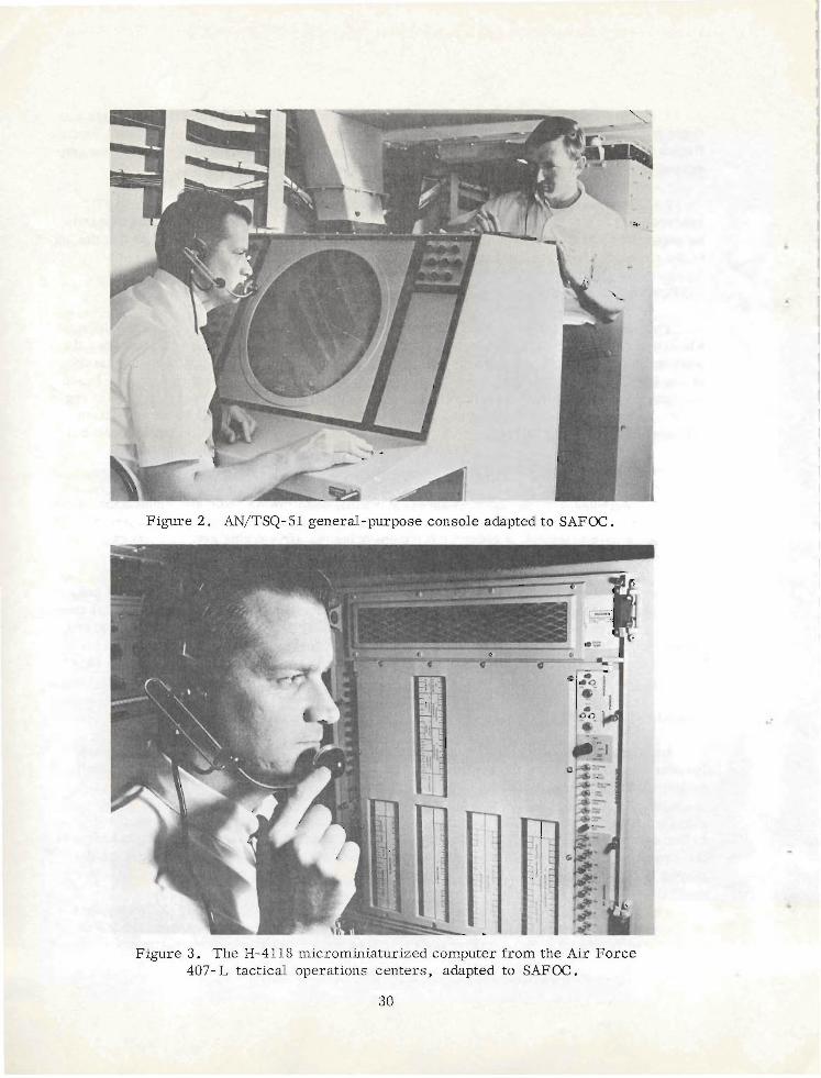
Figure 3. The H-4118 microminiaturized computer from the Air Force 407- L tactical operations centers, adapted to SAFOC .
The controller can call up certain displays in the performance of the flight-following or monitoring function; for example, a computer-generated map &splay could be presented. Such a map could be superimposed on the normal a i r situation to provide the composite dis- play of map data and aircraft symbols.
Although each flight plan is evaluated for conflict before final acceptance, there is always the possibility that changes o r delays will occur that generate new conflicts. Therefore, i t is planned that a new conflict evaluation be carried out for each aircraft every 10 to 20 sec- onds. This evaluation will be performed on flight plan and flight-following data and will include track data received from radar sources, such a s a i r defense.
Terminal and traffic densities will be monitored by the SAFOC. If the density builds up to dangerous levels, the en route aircraft will be diverted o r delayed until terminal condi- tions improve. Flight plans will be inactivated when a flight is handed over to an adjacent FOT: o r a subordinate FCC. Handover of flights will be under positive control of the control- l e r rather than completely automatic in order to avoid confusion about who is responsible at any given time.
RADAR INTEGRATION SUBSYSTEM
This subsystem provides the appropriate interface for any of a large number of standard radars currently in use by the military services. It accepts the position information from the radar and uses it a s any other input to the SAFOC.
MANUAL BACKUP SUBSYSTEM
Manual backup equipment is provided to help maintain a degree of operational effective- ness in the event of failure (or degraded operation) of the SAFOC. In the SAFOC under test this subsystem is comprised of a i r s tr ip racks and plot boards.
PRESENT STATUS
The SAFOC delivered to the Army in September 1969 will undergo an extensive two-phase test at the National Aviation Facilities Experimental Center (NAFEC) . Initially, the test will consist of canned and controllable simulated targets generated by NAFEC facilities.
Varying traffic loads will be applied to the SAFOC to determine the level at which the center is saturated. The successful completion of phase 1 will lead into phase 2 where live traffic,will be used. This phase will test the system's ability to manipulate traffic utilizing the following inputs: radar images, IFF response, altitude and position, and flightpath indi- cations. These inputs will be delivered to the SAFOC via the data link.
The results of this test will provide the basis for the development of an automated a i r traffic regulation system consisting of a family of en route and terminal facilities that is needed not only by the military but is certain to have value to civil aviation a s well.
History of Air Defense
Editor's Note:
This i s the fifth installment of "History of Air Defense," and now we look at the defensive aircraft tbat were in use just prior to the United States involvement in World War 11. We also take a look at US air defense operations between the great wars wbicb embraced pursuit aviation, antiaircraft artillery, radio equipment, barrage balloons, and passive defense measures in developing a system of unified air defense f m cities, vital areas, continental bases, and armies in the field.
In the United Kingdom by 1939, the World War I biplanes with speeds up to 135 miles per hour (mph) had been replaced with monoplanes having speeds of more than 360 mph and service ceilings up to 36,000 feet. This was about 50 mph faster and a service ceiling bf about 2,000 feet higher than contemporary United States planes. The British were equipping aircraft with self-sealing fuel tanks, bulletproof windshields, and armor protection for the pilot. The British planes were more maneuverable a t high altitudes and were equipped with twice a s many guns a s American fighters. The maximum range was about 700 miles .
In the 1920fs, increased engine power accounted for most of the advances. The Fairey Fox light bomber, which appeared in 1925, was powered by the American Curtiss D. 12 liquid- cooled, in-line engine and outperformed all single-seater fighter planes of that day. This marked the changeover to this type of engine by the British, with both Rolls- Royce and Napier producing such engines. From the modest 400 horsepower of an early model of the Kestrel, Rolls- Royce continually strove for better engines. A 1,900-horsepower engine powered the Supermarine float plane which won the Schneider Trophy in 1929, and in 1931 a Rolls-Royce R maintained2,783 horsepower for an hour during a bench test-a record not to be equaled by air-cooled engines until 1940.
The Schneider races led to the development of a fighter to use the larger engines. Rolls- Royce provided the Merlin series of engines which gained fame a s powerplants for the Hurricanes and Spitfires. New improvements in fuels and weapons paralleled engine develop- ment. Studies in 1934 by ballistics experts disclosed that fighters must have the capability of delivering a 2-second burst at the rate of some 1,000 rounds per minute from each of eight machineguns to insure a bomber kill.
By 1935 specifications contained requirements for a monoplane with a speed of 275 mph at 15,000 feet, 90 minutes' endurance, a ceiling of 33,000 feet, a rate of climb so that the plane could reach 20,000 feet in 7$ minutes, and a landing roll of only 250 yards. An inclosed cockpit, retractable landing gear with wheel brakes, oxygen for the pilot, eight machineguns firing 15 seconds, and a reflector sight were part of the specifications.
Although variable-pitch, constant-speed propellers had been designed a s early as 1925, it was not until 1935 that De Havilland began manufacturing such propellers. Production was for bombers to permit them full power on takeoff and optimum power during climb and cruise. Not until the Battle of Britain were these propellers put on Hurricanes and Spitfires, on a crash basis, to permit closer parity with German fighters.
The Gladiator biplane was put into production for the RAF in September 1935. In 1938, 32 Gladiator 11's were modified to operate from carriers. Production of the Navy version, the Sea Gladiator 11, was started in 1939. The Gladiator I1 had a maximum speed of 253 mph at 14,000 feet, a service ceiling of 33,000 feet, and a range of 425 miles. Armament consisted of four caliber .303 Browning machineguns.
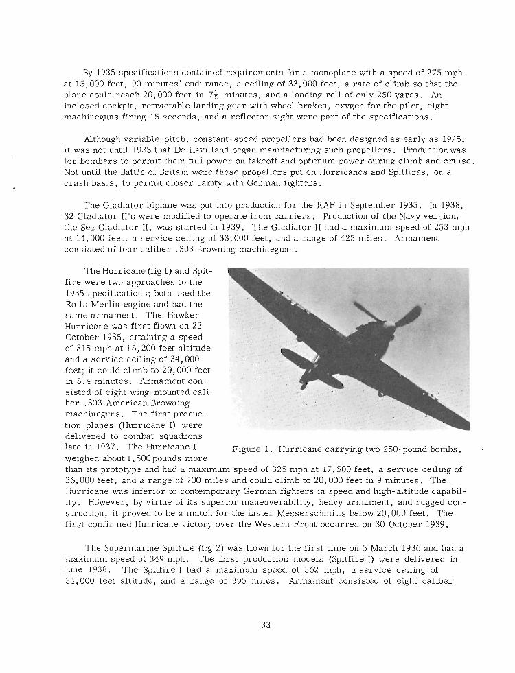
The Hurricane (fig 1) and Spit- fire were two approaches to the 1935 specifications; both used the Rolls Merlin engine and had the same armament. The Hawker Hurricane was first flown on 23 October 1935, attaining a speed of 315 mph at 16,200 feet altitude and a service ceiling of 34,000 feet; it could climb to 20,000 feet in 8.4 minutes. Armament con- sisted of eight wing-mounted cali- (i
ber .303 American Browning -. machineguns. The first produc- tion planes (Hurricane I) were delivered to combat squadrons late in 1937. The Hurricane I Figure 1. Hurricane carrying two 250-pound bombs. weighed about 1,500 pounds more than its prototype and had a maximum speed of 325 mph at 17,500 feet, a service ceiling of 36,000 feet, and a range of 700 miles and could climb to 20,000 feet in 9 minutes. The Hurricane was inferior to contemporary German fighters in speed and high-altitude capabil- ity. Hdwever, by virtue of its superior maneuverability, heavy armament, and rugged con- struction, it proved to be a match for the faster Messerschmitts below 20,000 feet. The first confirmed Hurricane victory over the Western Front occurred on 30 October 1939.
The Supermarine Spitfire (fig 2) was flown for the first time on 5 March 1936 and had a maximum speed of 349 mph. The first production models (Spitfire I) were delivered in June 1938. The Spitfire I had a maximum speed of 362 mph, a service ceiling of 34,000 feet altitude, and a range of 395 miles. Armament consisted of eight caliber
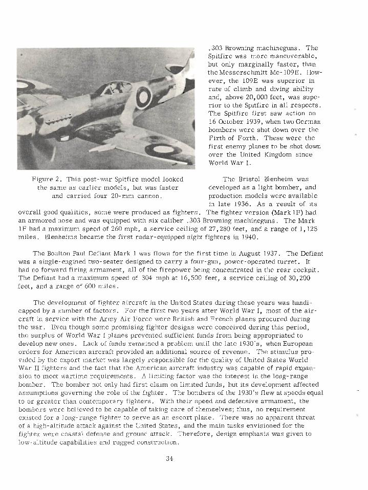
,303 Browning machineguns. The Spitfire was more maneuverable, but only marginally faster, than the Messerschmitt Me- 109E. How- ever, the 109E was superior in rate of climb and diving ability and, above 20,000 feet, was supe- r ior to the Spitfire in all respects. The Spitfire first saw action on 16 October 1939, when two German bombers were shot down over the Firth of Forth. These were the f i rs t enemy planes to be shot down over the United Kingdom since World War I.
r igure 2. This post-war Spitfire model looked the same a s earlier models, but was faster
and carried four 20-mm cannon.
The Bristol BZenheim was developed a s a light bomber, and production models were available in late 1936. As a result of its
overall good qualities, some were produced a s fighters. The fighter version (Mark 1F) had an armored nose and was equipped with six caliber .303 Browning machineguns. The Mark 1F had a maximum speed of 260 mph, a service ceiling of 27,280 feet, and a range of 1,125 miles. Blenheims became the first radar-equipped night fighters in 1940.
The Boulton Paul Defiant Mark 1 was flown for the f irst time in August 1937. The Defiant was a single-engined two- seater designed to carry a four-gun, power-operated turret. It had no forward firing armament, all of the firepower being concentrated in the rea r cockpit. The Defiant had a maximum speed of 304 mph at 16,500 feet, a service ceiling of 30,200 feet, and a range of 600 miles.
The development of fighter aircraft in the United States during these years was handi- capped by a number of factors. For the f irst two years after World War I, most of the air- craft in service with the Army Air Force were British and French planes procured during the war. Even though some promising fighter designs were conceived during this period, the surplus of World War I planes prevented sufficient funds from being appropriated to develop new ones. Lack of funds remained a problem until the late 1930'9, when European orders for American aircraft provided an additional source of revenue. The stimulus pro- vided by the export market was largely responsible for the quality of United States World War I1 fighters and the fact that the American aircraft industry was capable of rapid expan- sion to meet wartime requirements. A limiting factor was the interest in the long-range bomber. The bomber not only had first claim on limited funds, but its development affected assumptions governing the role of the fighter. The bombers of the 1930's flew at speeds equal to o r greater than contemporary fighters. With their speed and defensive armament, the bombers were believed to be capable of taking care of themselves; thus, no requirement existed for a long-range fighter to serve as an escort plane. There was no apparent threat of a high-altitude attack against the United States, and the main tasks envisioned for the fighter were coastal defense and ground attack. Therefore, design emphasis was given to low- altitude capabilities and rugged construction.
Fabric-covered biplanes were replacecl by all-metal monoplanes. Speeds increased from 135 rnph to 313 mph, service ceiling increased from 24,000 to 33,000 feet, horsepower increased from 350 to 1,200, and armament increased from two to four machineguns ; Other improvements included jettisonable fuel tanks, retractable landing gear, engine superchargers, and variable pitch propellers.
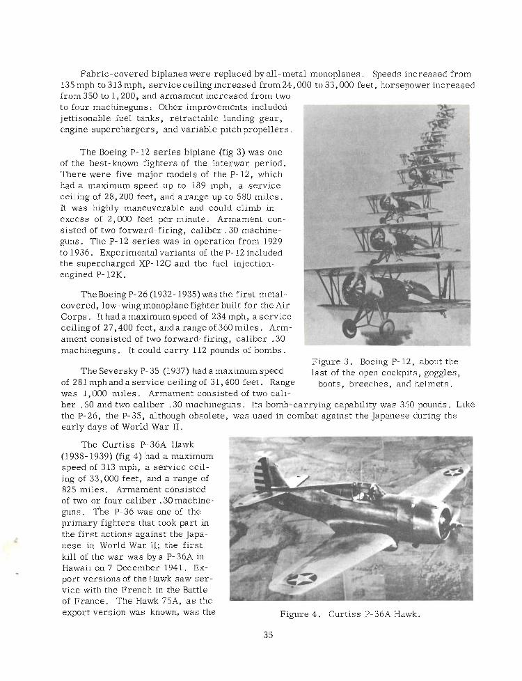
The b e i n g P- 12 series biplane (fig 3) was one of the best-known fighters of the interwar period. There were five major models of the P- 12, which had a maximum speed up to 189 mph, a service ceiling of 28,200 feet, and arange up to 580 miles. It was highly maneuverable and could climb in excess of 2,000 feet per minute. Armament con- sisted of two forward-firing, caliber .30 machine- guns. The P- 12 series was in operation from 1929 to 1936. Experimental variants of the P- 12 included the supercharged XP- 12G and the fuel injection- engined P- 12K.
The b e i n g P- 26 (1932- 1935) was the first metal- covered, low-wing monoplane fighter built for the Air Corps. It had a maximum speed of 234 mph, a service ceiling of 27,400 feet, and a range of 360 miles. Arm- ament consisted of two forward-firing, caliber .30 machineguns. It could carry 112 pounds of bombs.
Figure 3. Boeing P- 12, about the The Seversky P- 35 (1937) had a maximum speed last of the open cockpits, goggles,
of 281 rnph and a service ceiling of 31,400 feet. Range boots, breeches, and helmets was 1,000 miles. Armament consisted of two cali- ber .50 and two caliber .30 machineguns. Its bomb-carrying capability was 350 pounds. Like the P-26, the P-35, although obsolete, was used in combat against the Japanese'during the early days of World War 11.
The Curtiss P-36A Hawk (1938- 1939) (fig 4) had a maximum speed of 313 mph, a service ceil- ing of 33,000 feet, and a range of 825 miles. Armament consisted of two or four caliber .30 machine- guns. The P- 36 was one of the primary fighters that took part in the first actions against the Japa- nese in World War 11; the first kill of the war was bya P-36A in Hawaii on 7 December 1941. Ex- port versions of the Hawk saw ser- vice with the French in the Battle of France. The Hawk 75A, a s the export version was known, was the Figure 4. Curtiss P-36A Hawk.
3 5
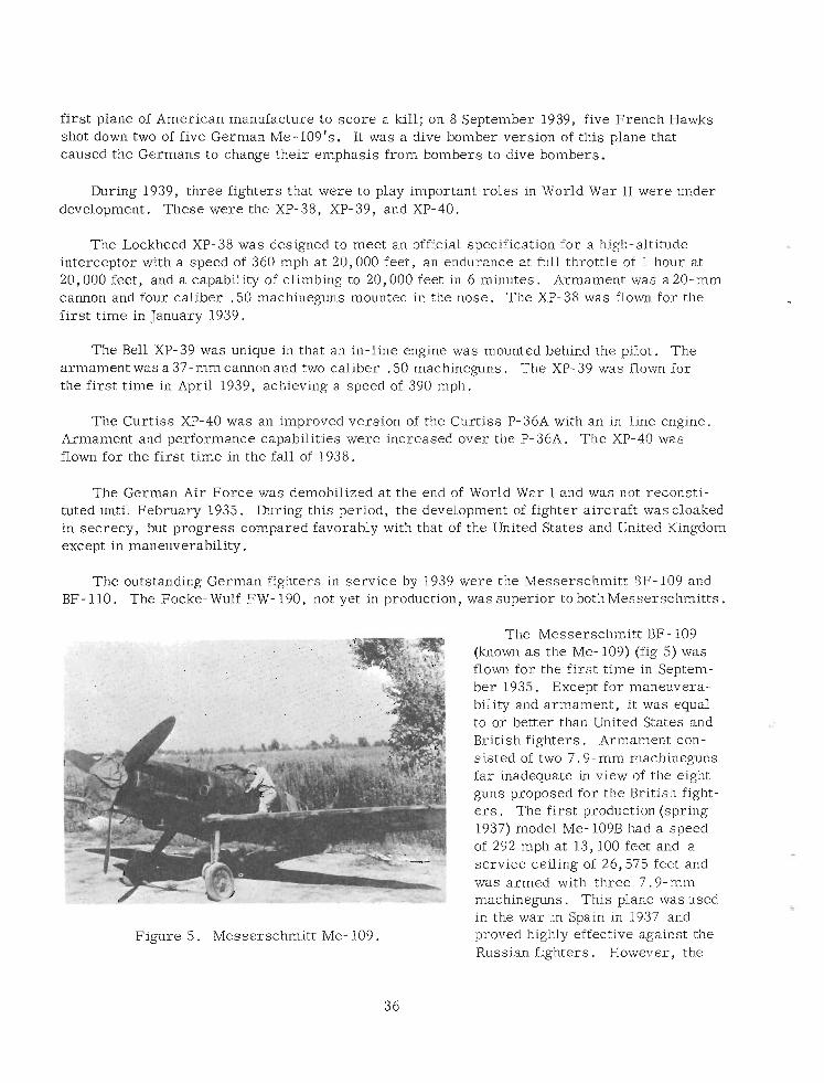
first plane of American manufacture to score a kill; on 8 September 1939, five French Hawks shot down two of five German Me-109's. It was a dive bomber version of this plane that caused the Germans to change their emphasis from bombers to dive bombers.
During 1939, three fighters that were to play important roles in World War II were under development. These were the XP- 38, XP- 39, and XP-40.
The Lockheed XP-38 was designed to meet an official specification for a high-altitude interceptor with a speed of 360 mph at 20,000 feet, an endurance at full throttle of 1 hour at 20,000 feet, and a capability of climbing to 20,000 feet in 6 minutes. Armament was a 20-mm cannon and four caliber .50 machineguns mounted in the nose. The XP-38 was flown for the first time in January 1939.
The Bell XP-39 was unique in that an in-line engine was mounted behind the pilot. The armament was a 37- mm cannon and two caliber .50 machineguns. The XP- 39 was flown for the first time in April 1939, achieving a speed of 390 mph.
The Curtiss XP-40 was an improved version of the Curtiss P-36A with an in-line engine. Armament and performance capabilities were increased over the P-36A. The XP-40 was flown for the first time in the fall of 1938.
The German Air Force was demobilized at the end of World War I and was not reconsti- tuted until February 1935. During this period, the development of fighter aircraft was cloaked in secrecy, but progress compared favorably with that of the United States and United Kingdom except in maneuverability.
The outstanding German fighters in service by 1939 were the Messerschmitt BF- 109 and BF- 110. The Focke-Wulf FW- 190, not yet in production, was superior to bothMesserschmitts.
-- The Messerschmitt BF- 109 (known a s the Me- 109) (fig 5) was flown for the first time in Septem- ber 1935. Except for maneuvera- bility and armament, it was equal to o r better than United States and British fighters. Armament con- sisted of two 7.9-mm machineguns far inadequate in view of the eight guns proposed for the British fight- - . -
e r s . The first production (spring 1937) model Me- 109B had a sveed
Figure 5. Messerschmitt Me- 109.
of 292 mph at 13,100 feet and ̂a service ceiling of 26,575 feet and was 'armed with three 7.9-mm machineguns. This plane was used in the war in Spain in 1937 and proved highly effective against the Russian fighters. However, the
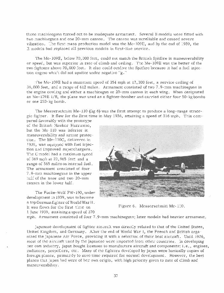
three machineguns turned out to be inadequate armament. Several B models were fitted with two machineguns and one 20-mm cannon. The cannon was unreliable and caused severe vibration. The first mass production model was the Me- 109E, and by the end of 1939, the E models had replaced all previous models in first-line service.
The Me- 109E, below 20,000 feet, could not match the British Spitfire in maneuverability or speed, but was superior in rate of climb and ceiling. The Me- 109E was the better of the two fighters above 20,000 feet. It also could outdive the Spitfire because it had a fuel injec- tion engine which did not sputter under negative "g."
The Me- 109E had a maximum speed of 354 mph at 12,300 feet, a service ceiling of 36,000 feet, and a range of 412 miles. Armament consisted of two 7.9-mm machineguns in the engine cowling and either a machinegun or 20-mm cannon in each wing. When designated a s Me- 109E 1/B, the plane was used a s a fighter-bomber and carried either four 50-kgbombs or one 250-kg bomb.
The Messerschmitt Me- 110 (fig 6) was the first attempt to produce a long-range strate- gic fighter. It flew for the first time in May 1936, attaining a speed of 316 mph . This com- pared favorably with the prototype of the British Hawker Hurricane, p:Aa"-.l:F- but the Me-110 was inferior in maneuverability and armor protec- tion. The ~ e - i l ~ ~ , delivered in 1939, was equipped with fuel injec- tion and improved superchargers. The C model had a maximum speed of 349 mph at 22,965 feet and a range of 565 miles on internal fuel. The armament consisted of four 7 .9- mm machineguns in the upper half of the nose and two 20-mm cannon in the lower half.
The Focke- Wulf FW- 190, under development in 1939, was to become a top German fighter of World War 11. It was flown for the first time on Figure 6. Messerschmitt Me- 110.
1 June 1939, attaininga speed of 370 mph. Armament consisted of four 7.9-mm machineguns; later models had heavier armament.
Japanese development of fighter aircraft was directly related to that of the United States, United Kingdom, and Germany. After the end of World War I, the French and British orga- nized the Japanese Air Force, providing it with a selection of their best aircraft. Until 1926, most of the aircraft used by the Japanese were imported from other countries. In developing her own industry, Japan bought licenses to manufacture aircraft and components; i. e. , engines, radiators, propellers, etc. Many of the fighters developed by Japan were basically copies of foreign planes, primarily to save time required for normal development. However, the best planes that Japan had were of her own origin, with high priority given to rate of climb and maneuverability.
The Kawasaki 95, designed in 1935, was a copy of the United States Curtiss Hawks of the P- 36 series. It was equipped with a 600-horsepower German BMW engine and had a maximum speed of 205 rnph and a range of 480 miles. Although not a fast plane, it was very maneuverable,
The Nakajima 95, built in 1935, was copied from the Boeing P- 12 series, The Na 95 had a maximum speed of 2 14.5 rnph and was very maneuverable.
The Mitsubishi 96, built in 1936, supposedly was developed from the United States Boeing P-26A. It had a maximum speed of 243 mph. Probably more of these were built than any other Japanese fighter, and it was common to both Arrny and Navy air services.
The Nakajima 97, built in 1937, was common to both the Army and Navy. It had a maxi- mum speed of 270 rnph at 15,000 feet altitude, a service ceilingof 32,000 feet, and a range of 460 miles .. Armament consisted of three 7.7-mm machineguns.
The Mitsubishi 97, also built in 1937, was common to both the Army and Navy. The Army version was armed with four 7.7-mm machineguns, had a maximum speed of 265 mph, a service ceiling of 29,000 feet, and a range of 375 miles. The Navy version, which carried only two machineguns, had a service ceiling of 30,000 feet and a range of 595 miles.
The Kawasaki 97, also built in 1937, was the same as the Mitsubishi 97 except for different armament and a more powerful engine. The K97 had a maximum speed of 290 rnph at 15,000 feet, a service ceiling of 32,000 feet, and a range of 335 miles, Armament consisted of three 7.7- mm machineguns.
The Kawasaki 98, built in 1938, was a biplane and appeared to be an improved version of the Kawasaki 95. The K98 had a maximum speed of 270 mph, a service ceiling of 32,000 feet, and a range of 350 to 400 miles. Armament consisted of two 7.7-mm machineguns and two 20- mm cannon.
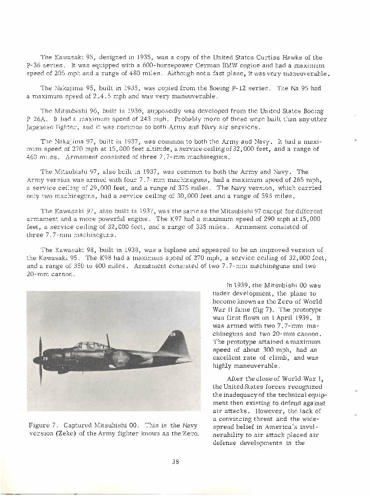
In 1939, the Mitsubishi 00 was
a convincing threat and the wide- Figure 7. Captured Mitsubishi 00. This is the Navy spread belief in America's m- version (Zeke) of the Army fighter known as the Zero. ner&iliq to air attack placed a&
defense developments in the
twenties and early thirties in a relatively low priority. Attempts were made to improve fighters and antiaircraft equipment, but emphasis was given to the ground support role of airpower.
The need for improved detection systems was recognized, and attempts were made at perfecting new and improved sound detectors. Parabolic reflectors for early warning were tested in detecting the sound of incoming planes, but the results were so poor that further research in the field of auditory detection was abandoned by the Army in 1933 (although improvement continued, culminating in the last of the antiaircraft sound locators, the improved M2). Other fields of detection, including infrared heat waves, were investigated by both the United Kingdom and United States, but interest ultimately became focused on detection by use of radio waves. (The British, in 1936, tested an airborne infrared detector which could detect aircraft at a range of about one-half mile. The infrared method was aban- doned due to i ts complexity, not to be revived until the Germans used infrared devices in 1944 for night driving and detection.) The true origins of modern military radar (radio detection and ranging) date from 1935 when the first practical microwave radio sets were developed. No one nation can be credited with all the discoveries leading to the development of radar, but the British registered the most rapid progress in devising its practical military application. Although both the US Army Air Corps and Coast Artillery Corps had supported the efforts of the Signal Corps to perfect early warning devices, the US Army lacked the funds and manpower needed to undertake a large- scale development of radar equipment and did not keep pace with the British.
Improved technology in bomber development, which by 1935 enabled United States bomb- e r s to match o r exceed the speed and altitude performance of United States fighters, gave r i se to the idea in some circles that the bomber was invincible. (The tenets of Guilio Douhet proclaiming the bomber a s the true master weapon were embraced also in England and, until the midthirties, in Germany.) Based upon experience gained in a joint Air Corps/antiaircraft artillery exercise at Fort Knox in 1933, during which a rudimentary ground observer corps was first used, Captain Claire L. Chennault claimed that fighters could intercept bombers successfully if operated in conjunction with an effective early warning system. The antiair- craft artillery established an antiaircraft intelligence service, using military personnel posted relatively short distances from the gun batteries for early warning and detection, but it proved inadequate for alerting fighters in time for interception. Systems were further tested and expanded, including the use of civilians a s observers. An exercise at Fort Bragg in 1938 again demonstrated that an aircraft warning net could provide invaluable aid to the fighters, a s well a s to antiaircraft units. The outbreak of war in Europe in 1939 enabled the United States to observe the combat testing of the British a i r defense system.
A first step was taken toward coordination of a i r defense when, early in 1940, the War Department activated the Air Defense Command at Mitchel Field, New York, to study the problems of an effective integration of a i r defense weapons and procedures. Although staffed by only 10 officers, this command studied the special capabilities of pursuit aviation, anti- aircraft artillery, radio equipment, barrage balloons, and passive defense measures in developing a system of unified a i r defense for cities, vital industrial areas, continental bases, and armies in the field. Eventually the British system, modified to meet United States needs, was adopted. Overall responsibility for continental a i r defense was assigned to GHQ
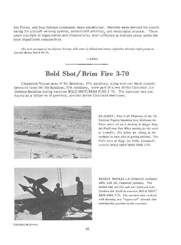
Air Force, and four defense commands were established. Methods were devised for coordi- nating the aircraft warning system, antiaircraft artillery, and interceptor aviation. These same concepts of organization and responsibility were reflected in oversea areas under the local department commanders.
The next account of air defense bistory will treat of Allied and enemy offensive aircraft employment in Europe during World War 11.
Bold Shot / Brim Fire 3-70 Chaparral/Vulcan units of 5th Battalion, 67th Artillery, along with two Hawk missile
batteries from the 5th Battalion, 57th Artillery,. were part of a new Strike Command Air Defense Battalion during exercise BOLD SHOT/BRIM FIRE 3-70. The exercise was con- ducted a s a follow-on of previous, similar Strike Command exercises.
I ON ALERT-Five F-4D Pbantoms of the 7tb Tactical Fiebter Sauadron from Holloman Air
I "
Force Base sit on a taxiway at Biggs A n y
Air Field near Fort Bliss waiting for the word
to scramble. Tbe pilots are sitting in tbe
coc&pits to save time in getting airborne. Tbe I P-4's were at Biees for Strike CommanrPs
DEADLY MISSILES-A Cbaparml evaiwfas
talk+ d 8 b tbe Cbapmrcrl operator. Tbe
oo&aircl~lft missile usit was deployed near
Coadtorr A&' Field in exevcise BOLD SHOT/
I BRIM FIRE 3-70. Tbe opersfor was credited
wdtb h ' n g two "aggressot" aircraf: tbat
I. atteded bis posirion & tbe exercise.
40
Modern Weapons of Air Defense Artillery Major Feden'co G. C. Landaburu
US Military Group, Argentina Washington, D. C.
This article was translated by Sergeant First Class Martin V. Rivera, US Army Air Defense School. Air Defense Trends does
not authorize use of this article, either in whole or in part, in other publications.
The technical advancement accomplished by the present aircraft has forced a i r defense to produce a better weapon system to maintain an a i r defense balance. The speed, aero- dynamic design, height capability, and tactics of offensive weapons employment have pro- vided the present aircraft with characteristics that permit action in short periods of time so that the human response needs the help of electronics in order to be efficient.
The equipment and materiel used by a i r defense artillery at the end of World War 11, normally antiaircraft cannon of long range, have been replaced by a new family composed of rockets and automatic cannon of small caliber that, when combined, will provide a good defense against an adversary at an adequate distance and with relatively great firepower. Electronics a r e used every day to discover the enemy's presence on his way to the objective and to find new ways, systems, and mechanisms to nulllfy the enemy's presence.
The complexity of this problem extends to all branches of the service in the operations theater who find themselves compelled to participate in a coordinated and integrated a i r defense system under one unified commander.
These a r e the principles of unity of command of maximum integration. This denotes that the present a i r defense cannot be improvised. The detection system to detect the air- borne invader should alert the defense in sufficient time to provide a prompt and effective response against the enemy; this in essence is what the a i r defense forces should provide.
The a i r defense artillery needs a variety of weapons. They should be flexible so that they can destroy o r nullify an enemy before he can accomplish his mission. This group of a i r defense weapons must be designed to accompany troops, not only in the organic require- ments of large units, but equipment weight and ease of facilitating its commitments must be considered.
We can say that the a i r defense cannon family of modern armies consists of 20 to 57 mil- limeters. Larger weapons must be discarded due to their weight, the time-consuming as- pects of their emplacement, their low efficiency, and the low projectile velocity. Missiles, on the other hand, fill this gap, reaching heights and areas beyond the reach of cannon and gradually increasing their capabilities and efficiency. The medium- and low-altitude employ- ment changes with the modification of the aerial means. The typical height that we knew 10 years ago has been altered by modern aircraft and its equipment, surpassing all past perform- ances. To operate at higher altitudes, the defense materiel should embrace other ranges. It is for this reason that it is practically impossible and inadequate to establish distance cate- gories of antiaircraft f ire based on low and medium altitudes by number.
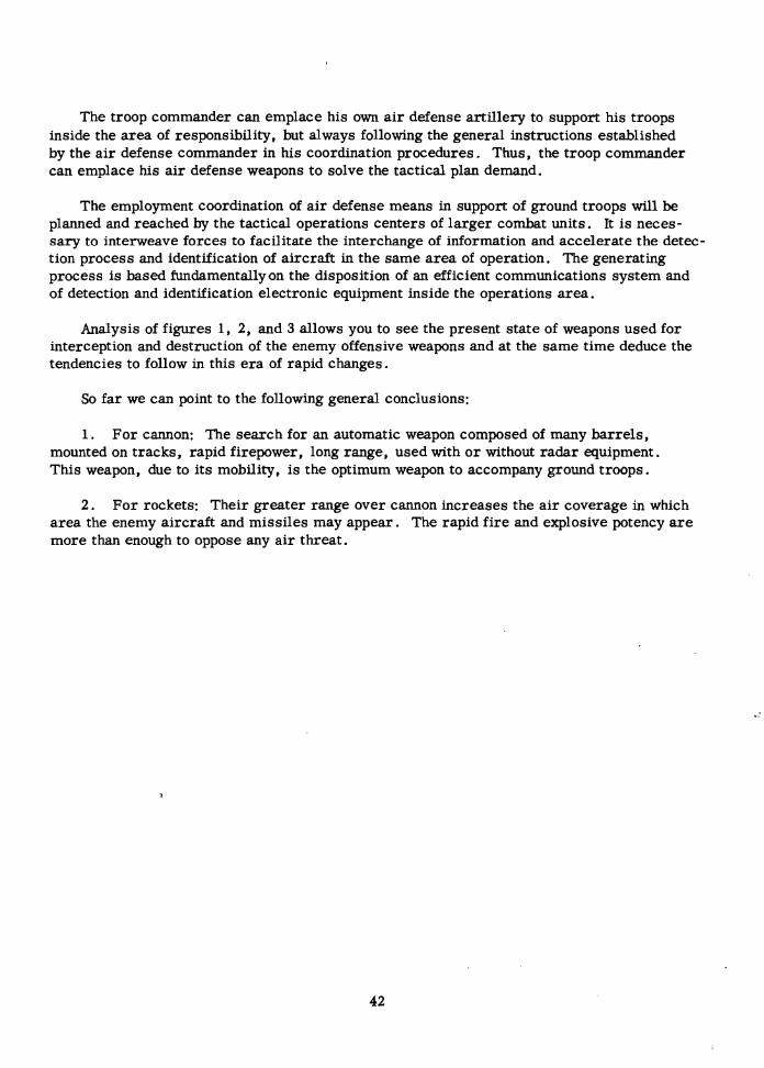
The troop commander can emplace his own a i r defense artillery to support his troops inside the area of responsibility, but always following the general instructions established by the a i r defense commander in his coordination procedures. Thus, the troop commander can emplace his a i r defense weapons to solve the tactical plan demand.
The employment coordination of a i r defense means in support of ground troops will be planned and reached by the tactical operations centers of larger combat units. It is neces- sary to interweave forces to facilitate the interchange of information and accelerate the detec- tion process and identification of aircraft in the same area of operation. The generating process is based fundamentally on the disposition of an efficient communications system and of detection and identification electronic equipment inside the operations area.
Analysis of figures 1, 2, and 3 allows you to see the present state of weapons used for interception and destruction of the enemy offensive weapons and at the same time deduce the tendencies to follow in this e r a of rapid changes.
So far we can point to the following general conclusions:
1. For cannon: The search for an automatic weapon composed of many barrels, mounted on tracks, rapid firepower, long range, used with o r without radar equipment. This weapon, due to i ts mobility, is the optimum weapon to accompany ground troops.
2. For rockets: Their greater range over cannon increases the a i r coverage in which area the enemy aircraft and missiles may appear. The rapid f i re and explosive potency a r e more than enough to oppose any a i r threat.
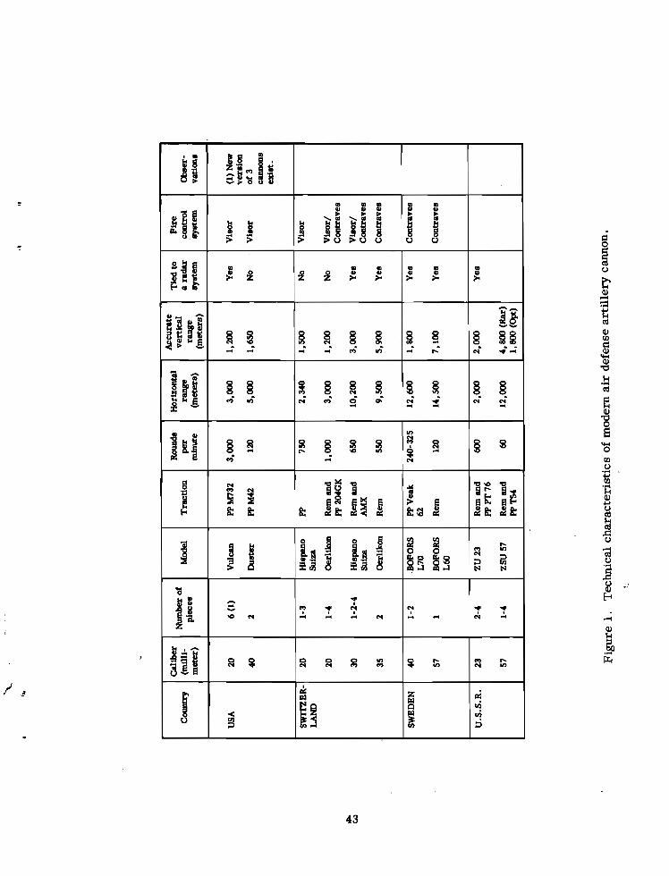
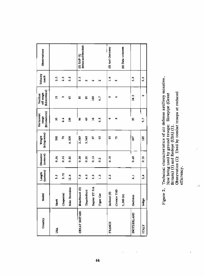
Figure 2. Technical characteristics of a i r defense artillery missiles. Now being used by ground troops: Blowpipe (Great Britain) (1) and Redeye (USA) (1). Observation (1): Used by combat troops at reduced efficiency.
* 0
- - - - - - . = - - I-' I ' * - ---I-
velocity mach
2.5
2.5
3.3
2.2
2
2
2
1.6
2
1.8
2.5
Observations
(2)RAF-Ej Swiss and Swedish
(3) And Germany
(4) Data unknown
Diameter (meters)
0.36
0.13
0.82
0.58
0.55
0.13
0.2
0.16
- - 0.40
0.19
Length (meters)
5.1
2.70
12.6
7.6
6.3
2.2
1.5
2.5
6.1
3.4
Country
USA
GREAT BFUTAIN
FRANCE
SWIl7, ERLAND
ITALY
Model
Hawk
Chaparral
Nike Hercules
Bloodhound (2)
Thunderbird
Rapier ET 316
Tiger Cat
Rolland (3)
Crotale THD
5.000 (4)
Oerlikon
Indigo
Weight (kilograms)
582
70
4.500
2.040
3.540
67
63
63
75
-
467
135
range wometers)
35
6.4
139
96
40
16
6.5
6
8
-
30
9.7
vertical eff range
(Idlometere)
15
3
45
30
20
133
4.7
3
6
-
14.5
6
a .- 4.4
E Q .z' .c 0 0 o m
$ E
n
3 :
LO
FI
LO
'El
5 6 & s t g g 3 4 j S z l
LO
FI
n
S : a l B
E e g Z ' B a l k 0
y * 1 &
13
1 C
e .- Y
g S
i: .YJ 2 $ a
w 6
8 B 5 z 6 E
n .c
8 f -1E
al
B - 8 B P
0 e
PI e
E
g e m -
I P 2 .- d -
m
0
LO
4 -
P
8
4- 0
z
m PI
4d O
* PI
5 b
'El Y g~ 3 , $ 8
pi g i . 2 s .Y o YE32 W , e s
@? PI 0 Y
cu 4
0
I
LO
m
Y)
c: U
B 13
8 a 4
8 4d a 0 *
A w
p s i b ~ : O
a s
i 1ZE 0 9 1 0
8 m w
m
/
a
E E m
3 $ ,a
0 .r m 4
d m
11)
N
? ? 0
LO
S
% $ 2 2 + 3 a a~
B LO 4
2 ,.4 o m
E 0 Y
2 m
2 j - ? 0 0 Y
4 0
m 0
Y) @?
- - * a g g
I = . z g w
5 $ $ g g E
LO
FI
5
Z , Z . r E I l :
m q n o E a l H Z
G g 5 g g z g a
LO
Y 0 m
5
i G 8 a l i! 5 $ . , $ $ s Z g * - a
= " ~ g t 9 & b , , z x g ~ 3 :
LO 0 Y
FI
0 N
o .F m -PI
LO
N
LO
0
LO
S
!z - 5 5 P o a g
- el rn 0
,.4
Y)
r n o 2 l . 2 a l n
d g , d - Y) 4
c
6 &
The Soviet Armed Forces Todav J
Contributed by Kenneth R. Whiting Air War College
United States Air Force Maxwell Air Force Base, Alabama
The somewhat bitter dialogue between Khrushchev and his marshals that marked the last two years of his tenure of office disappeared with his ouster. Thenew leaders, Brezhnev and Kosygin, have evinced no interest in competing with the military leaders in matters of strategy. For a matter of fact, no member of the Presidium has volunteered to act as an arbiter in military doctrine and the field is now the province of the military leaders themselves and what disputes ar ise a r e intramural, not between the marshals and the politicians. How long this situation will last is anybody's guess, but it is conceivable that any play for power by an aspirant for the jointly occupied Brezhnev- Kosygin throne can drag the military into the contest. Further- more, new appointments to top military jobs, which must be in the offing considering the ages of the present incumbents, may indicate the political leadership's strategical inclinations.
The age question is a serious one in the Soviet High Command. If the top eight commanders a r e listed, the result is a s follows: Grechko, Minister of Defense, 65; Yakubovsky, Commander- in-Chief of the Warsaw Pact Forces, 56; Zakharov, Chief of the General Staff, 70; Krylov, com- manderof the Missile Forces, 65; Batitsky, commander of PVO, 58; Gorshkov, headof the Navy, 58; Vershinin, Commander of the Air Forces, 68; and Bagramyan, commander of the Rear Forces, 70. This makes the average age around 64 years.
Not only a r e the military leaders, who a r e holding down the top slots, mostly in the advanced age bracket, but much of the advice proffered them through military journals, informal contacts, and in other ways comes from such oldsters a s Konev (71), Yeremenko (76), Sokolovsky (71), Rotmistrov (67), Chuykov (68), Moskalenko (66), and others equally old. Furthermore, most of these men held field commands of some importance in World W a r 11, mostly in the ground forces, and have a nostalgic preference for the more conventional services. All in all, young blood is not coursing wildly through the veins of the Soviet leaders at present in control of the establishment.
Although the composition of the Soviet Armed Forces would seem to indicate that its leaders a r e primarily concerned with preparations for another conflict of the World War I1 type, there have been some indications of a desire for more flexibility. For example, the Navy is now get- ting helicopter carriers, there is a growing marine contingent-berets and all, and an attempt is being made to increase the overall airlift capability. In spite of these steps, however, it does not look like an all-out effort to match the United States in Asia, Africa, and Latin America. The lack of aircraft carriers, the inability to secure sea lanes for worldwide operations, and the geographical position of the USSRmaybe the reasons for this reluctance. But an addiction to conventional land warfare on the continent probably is the main reason for the lack of interest in special forces and the means for maintaining them on a worldwide basis.
In the realm of nuclear weapons, missiles, long-range aircraft, and submarines, and the sophisticated, but not necessarily profound, argumentation that accompanies their
Kenneth R. Whiting-Born in Somerville, Massachusetts, in 1913. B.A. from Boston University, M.A. from U.C.L.A. and Ph.D. from Harvard. Taught history at Tufts University, 1947-1949; a t Suffolk University, 1950-1951; has been with Research Studies Institute, Air University, s ince 1951. Served in the Army Air Corps in the South Pacific, 1941-1945. Author of a number of studies for RSI. Also author of Background Information on the USSR, Ideologies in Conflict, and The Soviet Union Today: A Concise Handbook (Raeger, 1962).
employment, one suspects that the venerable Deputy Ministers of Defense must be relying on their younger colleagues for advice. Whether they either take it, o r can even appreciate it, is another question. The "Whiz Kids" of the Pentagon a r e a distinctly American phenomenon, a s i s the widespread addition to speculation on military strategy among scholars at American universities. In the Soviet Union, the discussion of strategy and military doctrine is still reserved to the military thinkers. But there must be lots of pent-up frustration among the younger military theorists a s they become aware that the road to the top i s more a matter of seniority than brilliance.
1. ORGANIZATION OF THE MINISTRY OF DEFENSE
The Ministry of Defense is one of the ministries controlled by the Council of Ministers, headed by a Chairman, A. N. Kosygin, a t the present time. But Soviet policies that need to be coordinated with the capabilities of the armed forces a r e made in the Politburo of the Central Committee of the Party, whose Fi rs t Secretary is L . I. Brezhnev, and of which Kosygin is also a member. Although the exact SOP i s not known, the military proffer advice when new policies concerning them are under consideration. In addition, there is a Military Section of the Central Committee which keeps constant watch on the Ministry of Defense.
Since March 1953 the Soviet military forces have been under a single Ministry of Defense. When Marshal Zhukov fell from grace in 1957, he was succeeded a s Minister of Defense by Marshal Rodion Ya. Malinovsky; upon the lat ter 's death in 1967, Marshal of the Soviet Union Andrey A. Grechko took over the job. The Minister i s advised by the General Staff, whose chief is now Marshal Matvey V. Zakharov, an officer who was closely connected with Malinovsky for twenty-five years . He also receives advice and assistance from a Military Council made up of commanders of the Main Administration such as the Ground Forces, the Air Forces, the Navy, the Missile Forces, and others. These commanders a r e Deputy Ministers of Defense and make up the core of authority in the Soviet Army.' But although they advise and ass is t the Minister of Defense, they a r e also directly responsible to him.
The Soviet Union proper is divided into the following fifteen military districts: Baltic, Leningrad, Moscow, Byelorussia, Carpathia, Kiev, Odessa, North Caucasus, Volga, Urals, Trans-Caucasus, Turkistan, Trans-Baikalia, Siberia, and the F a r East. The four major fleet commands (Baltic, Black Sea, Northern, and Pacific) a r e equivalent to military distr icts . Each military district i s semi-autonomous, responsible only to the Minister of Defense, and . .
has operational control of the military forces in i ts a rea except for those directly under the Ministry of Defense such a s PVO and the Long- Range Air Force units. The commander of the military district is usually a marshal o r top general, and along with his chief of staff and his chief political officer, usually a general, runs the military district through a Military Council composed of the three of them. The number and quality of the forces in each military district depend upon the district 's strategic importance. Some of these military districts would immediately become "Fronts" in t ime of war.
The Minister of Defense is also directly in charge of the three Soviet forces outside the USSR: the East German with 20 divisions, the Northern, 2 divisions in Poland, and the Southern, 4 divisions in Hungary, Marshal Yakubovsky, Commander- in-Chief of the Warsaw
h he First Deputy Ministers o f D e f e n s e are Yakubovsky, Zakharov, and Sokolov, and the Deputy Ministers are Bagramyan. Batitsky, Gorshkov, Krylov, and Pavlovsky. T h e s e , along with the Minister of D e f e n s e , Grechko, makeup the Military Council .
4 7
Pact Forces, is subordinate to the Soviet Minister of Defense and thus makes the Pact forces an integral part of the Soviet Armed Forces for all intents and purposes.
The Minister of Defense also has direct control of many of the forces that a re under the Main Administrations for housekeeping purposes. The Long- Range Air Force is an excellent example since it is represented at the highest level by Vers hinin in his capacity of commander of the Main Administration of the Air Forces and also depends on Vershinin for training, pro- curement, and other such activities, but in operations it is directly under the control of the Minister of Defense. As should be obvious, the command structure centers in one man, the Minister of Defense, and there is little chance of the various branches of the services, or the Warsaw Pact Forces, going off on tangents of their own. In other words, the situation of a semi-autonomous Navy a s was true between 1951 and 1953 has been well taken ca re of in the present centralized organization.
Political and Police Controls. Although almost 90 percent of Soviet officers and over 82 percent of the armed forces a s a whole a r e either members of the Party o r the Komsomol, the youth adjunct to the Party, the governing elite still does not trust them. It maintains two parallel hierarchies of control to insure their adherence to the straight and narrow, to insure that the military officers remain politically kosher. One of these control systems is the Main Political Administration of MPA, headed by a political officer, General of the Army A. A. Yepishev. The other is the military apparatus of the KGB, the secret police.
MPA functions a s part of the USSR Ministry of Defense and in one of the main administra- tions; but it is also a part of the Military Department of the Central Committee of the Party. MPA supervises and works closely with the Party and Komsomol organizations in the armed forces. These organizations a r e independent of local territorial Party organizations and directly responsible to MPA. The organizational structure of MPA follows the military chain of command. For example, the commanding officers of Fronts, fleets, military districts, and so forth all have their deputy commanders for political affairs. The same is true for divisional, regimental, and battalion commanders- each has his "zampolit" (deputy commander for political affairs). At the regimental and battalion level the zampolit conducts his educa- tional and propaganda work at the eyeball-to-eyeball level and tr ies to see to it that the troops do not have too much "leisure time. "
The central organization of MPA prepares the political instruction program, edits and publishes educational materials, and supervises the establishment and maintenance of army clubs, movie houses, and libraries. It also maintains schools for training zampolits .
The KGB organization also parallels the military MPA hierarchy. But KGB agents, although decked out in the uniforms and insignia of the units to which they a r e assigned, report directly to the KGB. They watch both the regular and the political officers, report on morale, and seek out any deviations from the accepted Party line.
The regular officers dislike the zampolit because he uses up too much of the training time and he also writes the ER on the officer's political reliability, a prime factor in promo- tion. The KGB agents, however, a r e not so much disliked a s feared. Their reputation over the last four decades has been so bad that nothing can eradicate the automatic chill down the spine when the name of the secret police is mentioned.
2. THE GROUND FORCES
As suggested above, the armed forces a re divided into Main Administrations, somewhat similar to the U.S. services, only more numerous. The five Main Administrations dealing directly with military forces a r e the Ground Forces, the Air Forces, the Strategic Missile Forces, the Air Defense Forces (PVO), and the Naval Forces. The term Ground Forces takes in the infantry, armor, artillery, engineers, and supporting services. It is the largest of the Main Administrations numerically, with some 1,500,000 to 2,000,000 men. The exact size of the Ground Forces is a much debated topic and most of the estimates a r e so blurred in places a s to instill legitimate doubts about the reliability of the counting process a s awhole. The usual guess is that there a r e about 130 to 140 divisions, but then comes the question of how many a r e combat-ready and up to full strength. Sokolovsky in his Military Strategy describes three degrees of readiness in the Soviet Armed Forces: combat ready, those 30 days off readiness, and those which will take 60 to 90 days to get up to full strength. The 26 divisions in Germany, Poland, and Hungary a r e combat ready. Some 40 to 45 divisions along the Western borders a r e in fair fighting trim; i .e. , those in the Leningrad, Baltic, Carpathian, Byelorussian, and Kiev military districts which will become "Fronts" in the event of a general war. Thus a good guess would be that there a r e between 65 and 70 divi- sions in good shape, and all a r e facing the NATO theater.
There a r e two types of divisions: armored, or tank, and motorized rifle. The armored division has about 9,000 men and 375 to 400 medium and heavy tanks when at its full strength. Its integral infantry is carried in armored personnel carr iers and it has its own artillery, anti-tank, and anti-aircraft units. The modern Soviet armored division is fast moving, has lots of firepower, and excellent vehicles, such a s the T-34 and T-54 medium tanks, theT- 10 heavies, and the PT-76 amphibious jobs. Many a r e equipped with infrared gear for night operations. There a r e probably 50 armored divisions a t various states of combat readiness, but the 13 stationed in Germany, Poland, and Hungary a r e in top shape.
The motorized rifle division is a modern version of the old infantry divisions, but now on wheels either truck o r armored personnel carriers. At full strength the division has 11,000 men and over 200 tanks, all medium. It also has its own anti-tank, and anti-aircraft and artillery units, a s well a s other support groups such a s communications and engineers.
The total tank strength of the Soviet Army is variously estimated from 30,000 to 70,000 ... vehicles, but inasmuch a s the 130 to 140 divisions would need around 40,000 tanks to fill in their To ' s that would seem to be a likely figure. The new T- 10 heavy tank is a 54-ton machine mounting a 122-mm gun and is an updated version of the famous JS model. The new medium T-54 is a 34-ton vehicle with a 100-mm gun, but a still newer T-62 medium tank with a 115-mm gun is replacing some T- 54's in "frontline" divisions. The PT-76, an amphib- ious beast, is relatively light and very fast, probably chiefly for recce work.
Artillery, long the "god of war" in the Soviet Armed Forces, has a more limited func- tion in the new types of divisions than it did in -World War 11, when whole "artillery armies" blasted holes through the German front. The older weapons a r e gradually giving way to relatively light anti-tank guns, anti-tank missiles, and anti-aircraft missiles. The very title of the artillery boss, Marshal of Artillery K . P. Kazakov, is Commander- in-Chief of the Rocket Forces and Artillery.
The Soviet leadership has been working hard to reorganize and train the Ground Forces to cope with the new conditions of nuclear warfare. They have been undergoing intensive training under simulated atomic attacks, and this means a change from the traditional Russian reliance on huge concentrations of manpower and enormous quantities of artillery, sitting ducks for nuclear attacks, and more reliance on smaller, semi- autonomous units. It also means more authority for the lower echelon commanders because of the necessity of dispers- ing the forces and the very likely probability that communications may be blacked out at times.
The Soviet Ground Forces today a r e mechanized, heavily endowed with firepower, equipped with a rather wide variety of tactical missiles with ranges from 10 to 140 miles, a s well as ground-to-air and anti- tank missiles. It should also be kept in mind that Soviet Frontal Aviation is closely integrated with and under the control of the Ground Force commanders.
3 . THE AIR FORCE
The Main Administration of the Air Force, headed by a Deputy Minister of Defense, Chief Marshal of Aviation K . A. Vershinin, is made up of the following autonomous and semi-autonomous branches: the Tactical Air Force, called Frontal Aviation (frontal'naya aviatsiya) by the Russians, the Aviation branch of the Air Defense Command (PVO), Long- Range Aviation, Military Transport Aviation, and Naval Aviation. Marshal Vershinin repre- sents all the branches of the Air Force in his capacity a s a Deputy Minister of Defense on the Military Council and as Commander-in-Chief of the Main Administration of the Air Force. He is responsible for procurement, training, and other housekeeping activities for all the branches. But operational control of Frontal Aviation is in the hands of the various Ground Force commanders to whom the units are assigned. Aviation of the WO, headed by Marshal of Aviation Ye. Ya. Savitsky, is subordinate to the WO commander, General of the Army P. F . Batitsky. Long- Range Aviation, under Marshal of Aviation F . A. Agaltsov, is directly responsible to Minister of Defense Grechko, as is Military Transport Aviation, headed by Lt . Gen. I. Taranenko. In short, Marshal Vershinin has administrative responsibility for all branches of the Air Forces, but operational control over practically nothing.
Frontal Aviation, the Tactical Air Force, has a total of around 4,000 aircraft (fighters, light bombers, reconnaissance, and transports). The twelve Frontal a i r armies2 are assigned to military districts, or peace-time Fronts, where they come under the operational control of the Ground Force commander. Although there are still many obsolescent MiG- 15 (Fagot), MiG 17 (Fresco) and IL- 18 (Beagle) aircraft in the inventory, newer types such as the MiG- 19 (Farmer), MiG21 (Fishbed), Su-7 (Fitter), and Su-9 (Fishpot) fighters and a supersonic light bomber, the Brewer, a re replacing the older types in the more favored districts.
The Aviation component of POV has over 5,000 aircraft, mostly MiG- 19's, MiG-211s, Su-7's, and Su-9's. There is also a new long-range interceptor, the Fiddler, equipped with air-to-air missiles coming into its inventory. As stated above, the interceptors of this branch of the Air Force a re under the control of Batitsky, commander of WO.
2 ~ n air army is the largest unit in the Soviet Air Force. In Frontal Aviation an air army is made up of three corps, and corps of three divisions. Each division has three regiments, and a regiment in turn i s composed of three squadrons.
Long-Range Aviation (DA) is made up of three a i r armies located in Western Russia, the Central Ukraine, and the Far East, with staging facilities in the Artic. It has a total strength of about 120 Bisoos, 80 Bears, and 900 Badgers and Blinders. Only the Bisons and Bears could reach the continental United States unrefueled, but the Soviets have been developing a refuel- ing capability over the last few years. In February 1968, Secretary McNamara stated that the Soviets had only 155 long-range bombers.
Military Transport Aviation, formerly the Aviation of Airborne Troops, has, among its other duties, the job of guaranteeing delivery of the Soviet airborne and parachute forces, probably totaling 7 divisions, about 60,000 men. But in addition to its own aircraft, Military Transport Aviation can call on Aeroflot, the Soviet Civil Aviation, now a ministry, which is really a military force on leave to the civil authorities. Aerflot has a very respectable fleet of jet-powered transports, a s can be seen from the following list:
LARGE AEROF LOT TRANSPORTS*
AN- 10: four- engine turboprop; 85 passepgers AN- 24: twin- engine turboprop; 46 passengers IL- 18: four- engine turboprop; 70 to 100 passengers IL-62: four-jet, rear-mounted; 182 passengers TU- 104: four- jet; 100 passengers TU- 1 14: four- engine turboprop; 120 to 220 passengers TU- 124: twin-engine turbofan; 40 to 60 passengers
Although the exact number of jet aircraft being used on Aeroflot lines is unhown, esti- mates put it well above 2,000. There a r e probably 500 to 600 TU- 104's, several hundred IL- 18's, sizeable numbers of TU- 124's, AN- lo's, and AN-24's, and a few TU- 114's and IL-62's. The surprise of the Le Bourget Air Show in June 1965 was the arrival of the gigan- tic AN-22 (Antaeus), which is capable of carrying 720 passengers and can (it is claimed) land on a 900-foot grass runway. Aeroflot's ability to supplement the 500 o r so aircraft of Military Transport Aviation is like the tail wagging the dog.
In summary, the Soviet Air Force has a total of well over 10,000 aircraft, not counting the 800 in Naval Aviation, which will be discussed later , and a total manpower of over 500,000 men.
4 . THE STRATEGIC MISSILE FORCE
In may 1960, Khrushchev, a real missile buff, announced the creation of a new Main Administration of the Soviet Armed Forces, the Strategic Missile Force, o r "Rocket Force of Strategic Designation, " in the Russian jargon. The first Commander- in- Chief was Marshal of Artillery M. I. Nedelin, but he was blown up in October 1960 when an experi- mental nuclear-fueled missile exploded on the test stand. He was succeeded by a leading member of the "Stalingrad Clique, " Marshal of the Soviet Union K . S . Moskalenko, who, when he became Chief Inspector of the Soviet Army in April 1962, handed the job over to Marshal of the Soviet Union S . S . Biryuzov . When Biryuzov became Chief of the General Staff in March 1963, he was succeeded by the present commander, Marshal of the Soviet Union N. I. Krylov . Just how the Strategic Missile Force is organized, the extent of Krylov's domain, and other details, a r e lacking. One thing seems certain, however; he has control of all ICBM's. He also probably has control of the IRBM's and MRBM's a s well.
'Source: K. R. Whiting. The Soviet Union Today. (Revised edition), New York, Raeger, 1966, p. 242.
5 1
The other 15 o r more types of missiles a r e under the operational control of the Navy, Ground Forces, and PVO. In July 1961 Marshal Malinovsky stated that tactical missile units were being organized, units capable of operating independently, thus insuring more flexibility. But he said nothing about how they were to be organized. On 23 February 1962, Marshal A. I. Yeremenko boasted that nearly 2,000 Soviet rocket units were operational and able to "hit the target with excellent precision." He must have been including every missile-equipped vessel in the Navy, all missile-carrying aircraft, the surface-to-air missiles of N O , and anything else that would fit into the category. He was obviously trying to impress the West.
The Strategic Missile Force's arsenal of ICBM's i s a number-one secret insofar a s it can be made so by the Soviets, but Secretary McNamara said in February 1968 that on 1 October 1967 the Soviets had 720 ICBM's, and most of these birds a r e second generation, which means that they a r e more easily adapted to hardened sites. Boosters have not been a major problem in Soviet rocketry, so their missiles can probably deliver rather large warheads, although not the plus- 50-megaton job so dear to the heart of Khrushchev .
The Soviets a r e wealthier in MRBM's and IRBM's, probably 700 to 800, a s their attempt to use them in Cuba demonstrated. These missiles have ranges varying from 700 to over 2,000 miles, depending upon the type, and a r e therefore capable of taking out targets in Western Europe. According to McNamara, the Soviet Strategic Forces (Strategic Missile Force, bombers, and submarines) can deliver up to 1,000 missile warheads and bombs on the United States.
5. THE AIR DEFENSE FORCE (PVO)
The Main Administration of PVO (protivovozdushnaya oborona-literally "anti- Aircraft defense") is split into two parts: PVO of the nation (strany), which is concerned with the overall defense of the nation, with its central headquarters near Moscow, and PVO of the armed forces, which is responsible for the a i r defense of the military units. General of the Army P. F . Batitsky is the Commmander-in-Chief of PVO, and his total personnel comes to around 250,000. Batitsky is directly subordinate to the Minister of Defense and thus opera- tionally independent of the military district commander in whose terri tory his PVO units a r e located.
PVO, in addition to its interceptor force under Savitsky which we have already discussed, has a system of radar-warning nets, anti-aircraft artillery, and surface-to-air missiles. The last named a r e rapidly assuming predominance in the PVO arsenal. The Guideline surface-to-air missile is a two-stage rocket with a range of 30 miles and an effective altitude of 80,000 feet. The Griffon, now becoming operational, has a greater range and altitude than the Guideline. Just how the Soviets a r e faring in the anti- ballistic missile field is a moot point, although in the May Day parades of 1965 and 1966 they trundled reputed ABM missiles through Red Square for the edification of the world.
Scuttlebutt has it that Soviet PVO communications, especially in the command and control area , leave much to be desired, but for some reason seem hard to improve. They also show a great reluctance to ever throw away anything no matter how obsolete. The consequence is a waste of manpower in the care and feeding of some rather useless equipment.
6. THE NAVAL FORCES
Since March 1953, immediately after Stalin's death, the Navy has been just another Main Administration of the Ministry of Defense. Admiral of the Fleet S. G. Gorshkov, a Deputy Minister of Defense and Commander-in-Chief of the Naval Forces, i s thus subordinate to a land-warfare-oriented group of superiors. Furthermore, ever since the Battle of Tsushima Straits in 1905, the Navy has played a subordinate role in Russian strategy, in spite of the valiant efforts of the admirals to glorify its achievements in the Great Fatherland War.
Geography 'is still conspiring against the Soviet sailors, and of the four main fleet com- mands, two a r e larid-locked (the Baltic and the Black Sea), one in the ice of the White- Barents seas, and only the Pacific command has relatively easy access to the high seas. The NATO powers, in control of the Turkish Straits and the outlet from the Baltic a s well a s having strong forces in the North and Norwegian seas, have the drop on the Soviet Navy a t the outset.
In spite of these handicaps, the Soviets have built up a really impressive surface fleet since World War 11. They now have 20 cruisers, around 170 destroyers, missile frigates, and destroyer escorts, and almost 600 torpedo and missile boats. Some of the cruisers and destroyers carry surface-to-air missiles. The Soviets have also recently commissioned two helicopter carr iers , a new turn in Soviet naval thinking.
The real Soviet offensive threat, however, is in its submarine fleet, one way of getting around some of the geogrpahical disadvantages of the USSR's location. As early a s July 1961 the Kremlin announced that it had a nuclear-powered submarine in operation. By 1967 the Soviets probably had around 50 o r 60 nuclear-powered submarines a s well a s over 300 conventionally-powered boats. One estimate i s that the production of nuclear-powered subs has leveled off at around ten per year. By stationing about two- thirds of the submarines, including all the nuclear craft, in the Northern and Pacific Fleets, the Soviets can gain access to the high seas with relative ease.
The Soviets have no attack aircraft carr iers , and, considering the geographical situation already mentioned, would probably find it hard to use them effectively if they did have them. In their propaganda they maintain quite dogmatically that in the e ra of long-range aircraft, missiles, and nuclear weapons, the aircraft carr ier is an extremely vulnerable target and a poor investment. But since this is also an e ra of stalemate in general war and since the action is now mostly in limited conflicts all over the globe, one has the feeling that behind much of the Soviet preaching about the vulnerability of aircraft carr iers there is a deep regret that a weapon system so useful in limited wars i s missing from their inventory. The two recently acquired helicopter carr iers in the Black Sea Fleet seem to be a step in the direction of filling that lacuna.
Naval Aviation, long the Cinderella of the Soviet Air Force, has been growing in impor- tance in recent years-partly one suspects because of the threat of the nuclear submarine and the Polaris missile system. Peculiarly enough, the commander of Naval Aviation Colonel- General I. Borzov wears two hats in that he is under the Commander-in-Chief of the Naval Forces, ~orshkdv , for operations, but subordinate to the Commander-in-Chief of the Air Force, Vershinin, administratively. The naval aviators have army ranks and fly army-type aircraft for the most part. Whatever the tugging and pulling may be, naval aviation has been getting better planes in the last few years-maybe because there a r e more available.

Estimates of the number of aircraft belonging to the Navy a r e extremely variegated, ranging from 4,000 to 800. Asher Lee: in 1962, put the total at 3,500, while the London Institute for Strategic studies4 put it a t 800 in 1965. - Time Magazine (23 February 1968) says 750. The London group divides the inventory in half, 400 bombers and 400 aircraft of other types. All evidence points to a rapid increase in the use of medium- and long-range aircraft (Badgers, Blinders, and Bears) for antisubmarine surveillance and early warning.
There a r e numerous other indications of the seriousness of the Soviet drive for naval f
supremacy, Gorshkov was made Admiral of the Fleet of the Soviet Union in 1967, a five-star i rank, and he is only the third sailor in Russian naval history to attain that honor. The Soviet r fishing fleet, over 4,000 vessels, is the largest and most modern in the world, and it does - i
I
more than just fish-it is also an intelligence-gathering force. The 200- ship oceanographic fleet is a model of efficiency. The addition of w e r a hundred landing craft and some 10,000 i
Naval Infantry (marines) indicate a move toward more flexibility in operations throughout the 1 world. I
The Russians, in spite of centuries of frustration in attempting to become a great naval power, seem to be at it again. But this time, because of technological advances, especially the nuclear submarine, they may have a greater chance of becoming a major competitor for the control of the seas.
8. THE TOTAL THREAT
The Soviet leaders, a s is obvious from the data just presented, have a t their disposal one ,
of the mightiest conglomerations of armed strength ever created. The Soviet Ground Forces with well over 100 combat-ready o r nearly ready divisions well supplied with all the modern i
I
means of firepower, an Air Force with over 10,000 first-line aircraft, a Navy boasting an I
ocean-going submarine fleet of over 300 boats, and a Strategic Missile Force with around ! 720 ICBM's and 700 medium- and intermediate-range missiles, when taken together make up a formidable military force, to say the least. If the million troops and 3,000 aircraft of the European satellites a r e added to the Soviet military threat, the result is a Soviet-controlled troop strength of well over four million men. J
1
Fortunately for the Western powers, the disparity in total military forces is not too far out of line since NATO forces come to a respectable total. Furthermore, large masses of men plunging about the European continent a r e no longer the "style" of modern war. The U. S. arsenal of 1,054 ICBM's, SAC'S fleet of heavy bombers, and the 75 nuclear-powered subma- rines equipped with Polaris missiles combine to make even the most belligerent Kremlin strategist reluctant about unleashing a general war. Unless a large part of the opponent's strategic capability can be eliminated before being launched, no all-out war can be anything except an exercise in mutual devastation, a cost far beyond any gains to be achieved by an all- out war.
Soviet military theorists, at least those publishing in open sources, however, seem to think only in terms of a general war on the Eurasian continent. The Soviet military forces
3 ~ h e Soviet Air Force, N.Y., John Day, 1962, p. 151.
4 ~ h e Military Balance 1965-1966. p. 5.
a r e largely constructed in accordance with this thinking, and little attention has thus far been paid to the types of forces and equipment that would facilitate the use of Russian troops outside of Europe, especially in Southeast Asia, Africa, and Latin America. This study, fortunately, is not concerned with Soviet military theory per se, but with the development of the Soviet Armed Forces. What the leaders decide to do with the enormous military force they have sweated to build is another question.
Editor's Note:
More recent information indicates tbat Russia now bas at least as many ICBM's as tbe United States, has begun building aircraft cam'ers, and now bas a formidable Mediterranean fleet.
British Radar Success British scientists have produced radar se ts without tubes o r transistors, the main
sources of breakdowns.
After three years of research, the f irst two solid-state sets using microcircuits have been built at Decca's Marine Radar Group Laboratories. The Laboratories' experts devised the new system with assitance from British universities and scientists working for the American space program.
A Decca director said: "It is a major breakthrough. Investigations showed that the main cause of unreliability in marine radar sets was tubes and transistors, which we have now done away with. "
The research team, headed by Decca's chief engineer, also found that the system holds down the cost of the sets and gives a better picture than existing ones. The Board of Trade and its American and German equivalents have approved the new sets .
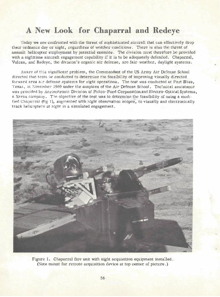
A New Look for Chaparral and Redeye Today we a r e confronted with the threat of sophisticated aircraft that can effectively drop
their ordnance day o r night, regardless of weather conditions. There is also the threat of assault helicopter employment by potential enemies. The division must therefore be provided with a nighttime aircraft engagement capability if it is to be adequately defended. Chaparral, Vulcan, and Redeye, the division's organic air defense, a r e fair- weather, daylight systems.
Aware of this significant problem, the Commandant of the US Army Air Defense School directed that tests be conducted to determine the feasibility of improving visually directed forward area a i r defense systems for night operations. The test was conducted at Fort Bliss, Texas, in November 1969 under the auspices of the Air Defense School. Technical assistance was provided by Aeronutronic Division of Philco- Ford Corporation and Electro- Optical Systems, a Xerox company. The objective of the test was to determine the feasibility of using a modi- fied Chaparral (fig l), augmented with night observation sco~es". to visuallv and electronicallv track helicopters a t night in a simulated engagement.
Figure 1. Chaparral f i re unit with night acquisition equipment installed. (Note mount for remote acquisition device at top center of picture. )
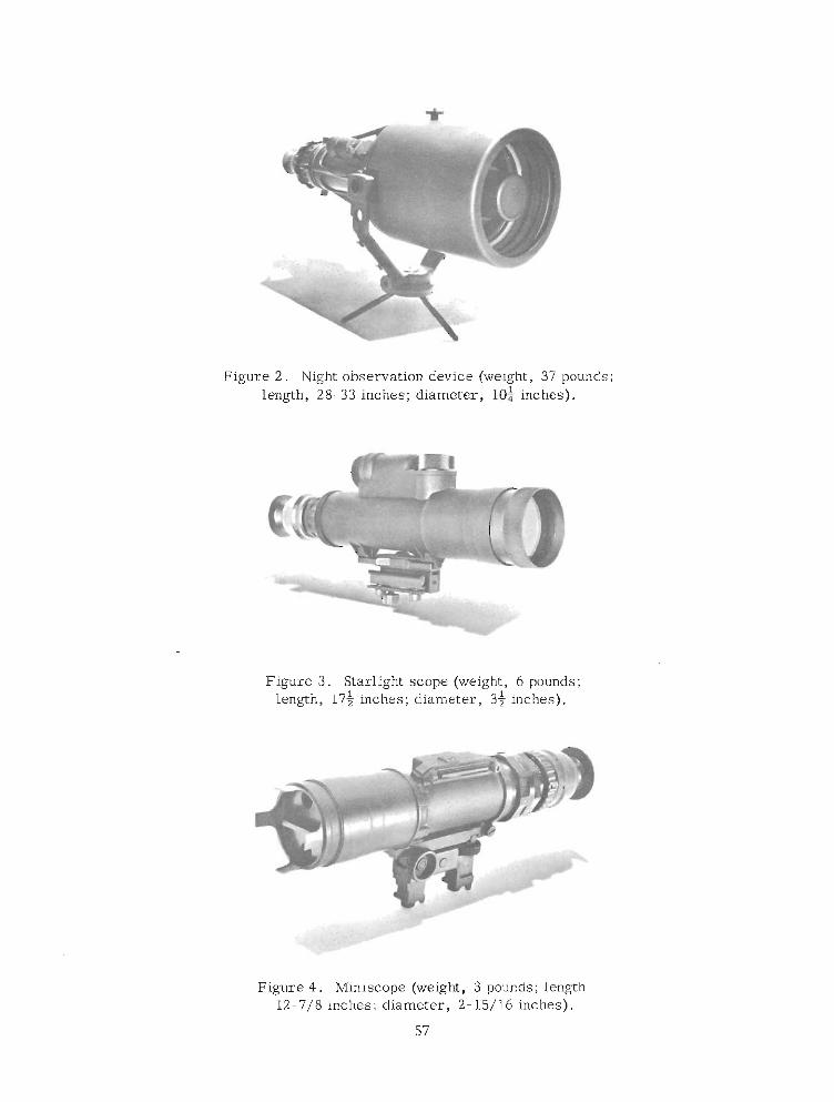
Figure 2. Night observation device (weight, 37 pounds; length,' 28-33 inches; diameter, 10i inches).
Figure 3. Starlight scope (weight, 6 pounds; length, 17$ inches; diameter, 34 inches).
Figure 4. Miniscope (weight, 3 pounds; length 12- 7/8 inches; diameter, 2- 15/16 inches).
57
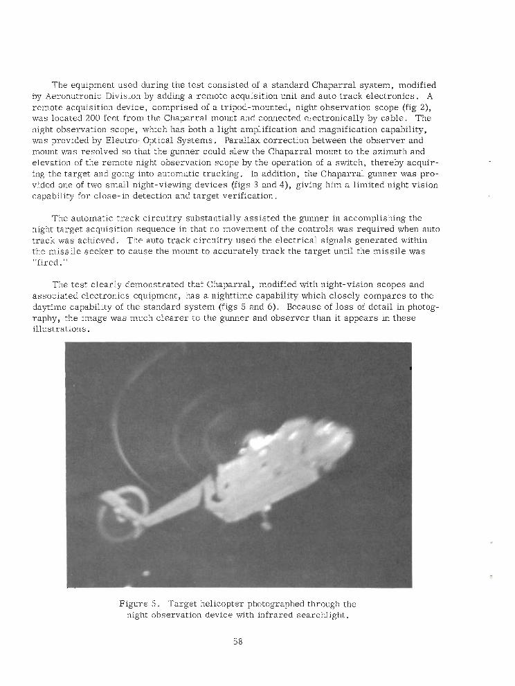
The equipment used during the test consisted of a standard Chaparral system, modified by Aeronutronic Division by adding a remote acquisition unit and auto track electronics. A remote acquisition device, comprised of a tripod-mounted, night observation scope (fig 2), was located 200 feet from the Chaparral mount and connected electronically by cable. The night observation scope, which has both a light amplification and magnification capability, was provided by Electro- Optical Systems. Parallax correction between the observer and mount was resolved so that the gunner could slew the Chaparral mount to the azimuth and elevation of the remote night observation scope by the operation of a switch, thereby acquir- ing the target and going into automatic tracking. In addition, the Chaparral gunner was pro- vided one of two small night-viewing devices (figs 3 and 4), giving him a limited night vision capability for close- in detection and target verification.
The automatic track circuitry substantially assisted the gunner in accomplishing the night target ~cquisition sequence in that no movement of the controls was required when auto track was achieved. The auto track circuitry used the electrical signals generated within the missile seeker to cause the mount to accurately track the target until the missile was "fired. "
The test clearly demonstrated that Chaparral, modified with night-vision scopes and associated electronics equipment, has a nighttime capability which closely compares to the daytime capability of the standard system (figs 5 and 6 ) . Because of loss of detail in photog- raphy, the image was much clearer to the gunner and observer than it appears in these illustrations.
Figure 5. Target helicopter photographed through the night observation device with infrared searchlight.
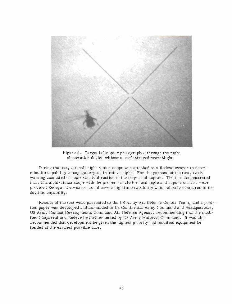
Figure 6. Target helicopter photographed through the night observation device without use of Infrared searchlight.
bring the test, a small night-vision scope was attached to a Redeye weapon to deter- mine its capability to engage target aircraft at night. For the purpose of the test, early warning consisted of approximate direction to the.target helicopter, The test demonstrated that, if a night-vision scope with the proper reticle for lead angle and superelevation were provided Redeye, the weapon would have a nighttime capability which closely compare's to its daytime capability.
Results of the tegt were presented to the US Army Air Defense Center Team, and a posi- tion paper was developed and forwarded to US Continental Army Command and Headquarters, US Army Combat Developments Command Air Defense Agency, recommendhg that the modi- fied Chaparral and Redeye be further tested by US Army Materiel Command. It was also recommended that development be given the highest priority and m-ed equipment be fielded at the earliest possible date.
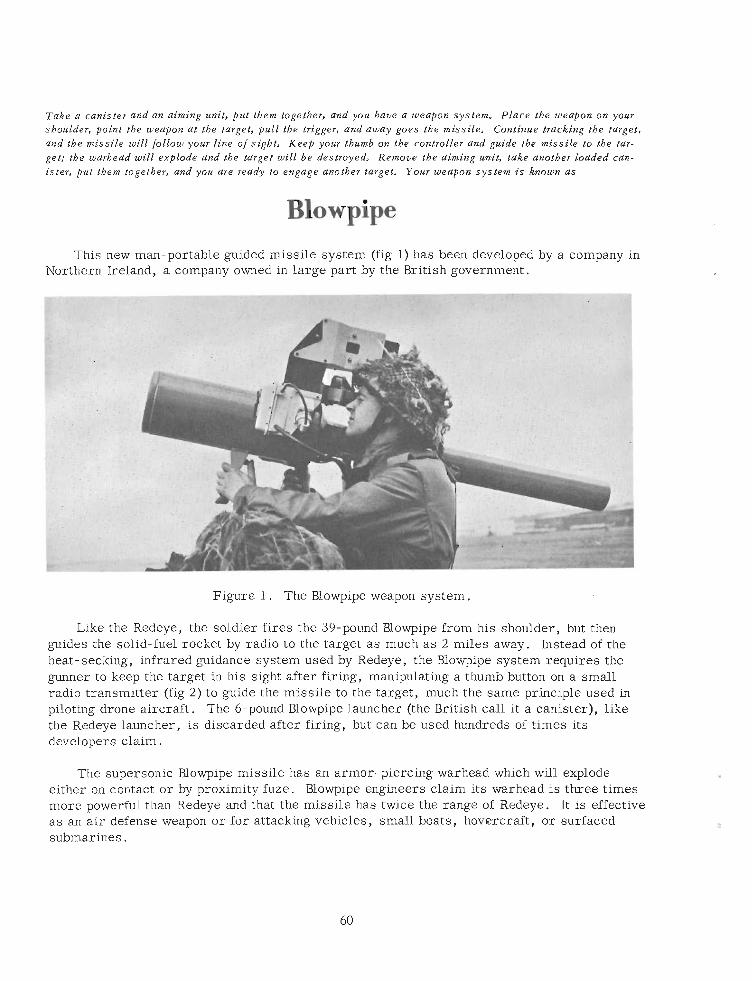
Take a canister and an aiming unit, put them together, and you have a weapon system. Place the weapon on your shoulder, point the weapon at the target, pull the trigger, and away goes the missile. Continue tracking the target, and tbe missile will follow your line of sight. Keep your thumb on the controller and guide the missile to the tar- get; the warhead will explode and the target will be destroyed. Remove the aiming unit, take another loaded can- ister, put them together, and you are ready to engage another target. Your weapon system i s known as
Blowpipe This new man-portable guided missile system (fig 1) has been developed by a company in
Northern Ireland, a company owned in large part by the British government.
Figure 1. The Blovlipipe weapon system.
Like the Redeye, the soldier fires the 39-pound Blowpipe from his shoulder, but then guides the solid-fuel rocket by radio to the target as much as 2 miles away. Instead of the heat- seeking, infrared guidance system used by Redeye, the Blowpipe system requires the gunner to keep the target in his sight after firing, manipulating a thumb button on a small radio transmitter (fig 2) to guide the missile to the target, much the same principle used in piloting drone aircraft. The 6-pound Blowpipe launcher (the British call it a canister), like the Redeye launcher, is discarded after firing, but can be used hundreds of times its developers claim.
The supersonic Nowpipe missile has an armor-piercing warhead which will explode either on contact or by proximity fuze. Blowpipe engineers claim its warhead is three times more powerful than Redeye and that the missile has twice the range of Redeye. It is effective as an air defense weapon or for attacking vehicles, small boats, hovercraft, or surfaced submarines.
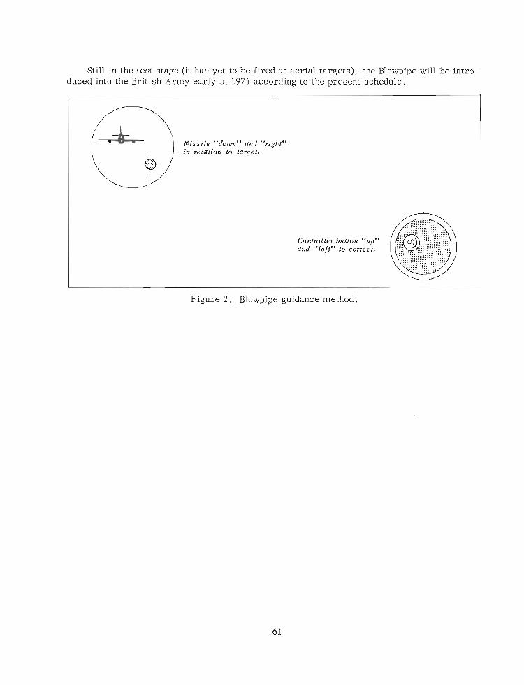
Still in the test stage (it has yet to be fired at aerial targets), the Blowpipe will be intro- duced into the British Army early in 1971 according to the present schedule.
Missile "down" and "right" in relation to target.
Figure 2. Blowpipe guidance method.
Aegis Navy's Nix on Styx
Reprinted /+om GOVERNMENT EXECUTIVE, February 1970 Copyrigbt , Reinbold Publishing C O T ~ O M ~ ~ ~
For roughly a decade the United States Navy has been confronted with the problem of Russian- built cruise missiles, unmanned plane- shaped weapons that have the capability of flying just above the waves with terminal guidance to "home in" on enemy shipping.
Since 1960 o r 1961, the Navy has known of the existence of the Russian Styx, a cruise missile of 15 miles range o r more, with which some 125 fast Russian patrol boats a r e reported to be equipped. Around 1962, the year of the Cuban missile cr is is , the Soviets sup- plied *- equipped patrol boats to Cuba, Egypt, Communist China and Indonesia. In addi- tion, more than a score of larger Russian warships were armed with cruise missiles of longer range. One of theselonger-rangemissiles may be the Shaddock which, according to the unofficial Institute of Strategic Studies in London, has a range of 250 statute miles and can deliver a nuclear warhead.
Soviet development and proliferation of the Styx attracted little public attention in this country until October 21, 1967. On that date the Egyptians used their Russian- built 75- ton Korman-class patrol boats and Styx missiles to sink the 2,300-ton Israeli destroyer Eilath. Three 1,000-pound high explosive warheads crashed into the destroyer, taking 47 lives and wounding 9 1 .
In Congress, the sinking focused attention on cruise missiles.. Congressmen learned that they a r e not ballistic, with high-arching trajectories like intercontinental ballistic mis- si les, but generally a r e aerodynamic types which fly a t low altitudes and have terminal guid- ance systems to cause them to home into targets. Soviet cruise missiles can be fired from surface ships, surfaced submarines and shore launchers. The U.S. Navy has no cruise missiles of i ts own, having had several and retired the latest, strategic, nuclear-armed Regulus , in favor of Polaris submarines and their ballistic nuclear missiles. On the other hand, the U.S. Navy has aircraft carr iers , of which the Soviets have none.
Navy officials testified that our defenses against cruise missiles comprised:
*~econnaissance, intelligence and a i r attack to locate and destroy launch sites and mis- siles before use.
*Electronic countermeasures to detect and deceive the missile in early flight.
*Counterfire by guns and surface-to-air missiles (SAMs) to destroy the missile in flight.
In addition, Navy spokesmen said, their research and development program was engaged in efforts to improve defenses. A
Dr. Robert A. Frosch, Assistant Secretary of the Navy for Research and Development, explained one of the problems involved.
The radars for which ship-size antennas could be built conveniently do not see over the horizon, he said, so the target ship f irst sees the missile when it comes over the radar hori- zon. Even with a subsonic missile such a s *, the available response time is very short.
Since the sinking of the Eilath, the Navy has taken a number of steps to improve defenses against cruise missiles.
To improve reliability of antiaircraft missiles that might be used against the cruise mis- siles, it has undertaken to replace Tartar and the major portion of Terr ier with its Standard missile, which has a range of more than 20 miles and a conventional warhead. Production of Tartar and Ter r i e r has been stopped but Talos, with a range of over 65 miles and the ability to carry either a nuclear o r high explosive warhead, is still being produced.
The Basic Point Defense Surface Missile System, a simple and relatively low cost anti- aircraft system, became operational about a year ago. Using a Sparrow I11 missile guided by a manually operated f i re control system, it can be installed on smaller vessels-amphib- ious and auxiliary ships a s well a s combat types.
The latest and largest step resulted, the Navy said, from initial planning begun in 1964 before the Eilath sinking. It was the award last month of a $252.9-million contract to RCA Defense Electronics Products Division for the engineering development of a new advanced surface missile system, named Aegis for the shield of an ancient Greek deity.
"It is planned a s the defensive surface-to-air missile system for the new guided missile ships scheduled to join the fleet in the mid- 1970ts," the Navy said. "The new system is designed to destroy small, fast targets in hostile environments such a s severe weather o r countermeasure conditions, and is the Navy's answer to the threat of anti-shipping missiles. Ships armed with Aegis will be capable of defending a task force including ca r r i e r s and other types of ships. "
Two features a r e an electronic scanning radar able to look in all directions almost instantaneously, the announcement said, and a dual- purpose launcher which can f i re rocket- propelled anti-submarine weapons a s well a s guided antiaircraft missiles. In addition, the Aegis radar and related subsystems a r e designed to aid in controlling friendly aircraft and to locate hostile a i r targets for surface-to-air missiles.
Additional components will include a newly designed data system computer and illumina- tors for missile guidance. An illuminator is a source of energy that illuminates the target so that a missile can see it without itself being burdened with the tremendous amount of power required for such illumination. A radar signal bounced off the target by Aegis will be picked up and used for guidance by the defending missile, which will be an evolution of the Standard missile system.
"The system is designed for installation a s a unit in new missile ships, either initially o r a s a conversion, " the Navy said. "The radar system is also suitable for installation in new aircraft carr iers .
"The system will be aimed at area defense. Area defense, as opposed, for example, to point o r single-ship defense, means that Aegis will be capable of defending an area of ocean which might include a carrier o r other type of task force."
RCA officials estimated that, subject to performance milestones and continuing authori- zations and appropriations by Congress, the project may involve a total expenditure of around $1 billion eventually. Capt. John P. Tazewell, USN, is the program manager.
Sometime between now and June 30, the Navy plans further action that some observers will regard as a sequel to the Eilath sinking. That action will be to go to contract definition in a program to develop an anti-shipping missile of its own, the Harpoon, which will carry a conventional warhead and can be launched from either ships o r aircraft. -one-time publication by
special permission of Reinhold Publishing Corporation.
Air Force Seeks New Air-to-Air Missile The Air Force, seeking to replace its Sparrow, Sidewinder, and Falcon missiles which
it says a r e obsolete, has asked 11 companies to submit proposals for developing a new air-to-air missile to be known a s the AIM- 82. Eventually, two contractors will be chosen to build competitive missiles for testing.
The AIM-82 is envisioned a s the main armament of the new F- 15 jet fighter, the new Navy F14 jet, and such existing aircraft a s the F4. If development proceeds smoothly, the new missile will replace all air-to-air missiles in the Air Force inventory. Like the Sidewinder, the AIM- 82 will be an infrared missile guided by heat- seeking devices.
Editor's Note:
The letters, AIM, are symbols indicating, respectively, a ir , intercept-aerial, and p i d e d missile (AR 705-76).
Tracer Observation for Air Defense Fire Control
Robert D, Baldwin, Ph.D. Human Resources Research Organization
During 1967 and 1968, Joint Task Force Two UTF-2) of the Joint Chiefs of Staff was planning tests to evaluate ground-based a i r defense weapons. During this planning, a debate arose within the Task Force concerning the usefulness of t racer observation a s a fire control technique. Several gun-type air defense weapons have used tracer observation either a s a primary or an auxiliary technique for adjusting fires. Although tracer observation has been used for automatic weapon fire control for years, highly divergent opinions have existed among military commanders concerning its effectiveness . HUMRRO was requested to eval- uate this problem. This article summarizes the results of the HUMRRO research.
The HUMRRO research was concerned with the following problems:
1. How a r e tracers used for air defense fire control purposes?
2. What human, physical, and environmental factors influence the effectiveness of tracer observation?
The study was limited to survey of existing information sources concerning tracer obser- vation. The information sources consisted of informal interviews with (1) officers and enlisted men who had experience in the use of this method of a i r defense fire control, (2) sci- entists and engineers who had participated in previous tests o r had World War I1 experience with air defense weapons, and (3) a review of military and human factors literature relevant to the problem.
The basic purpose of tracer observation is to provide feedback to the gunner concerning the accuracy with which he has determined the correct line and lead angles. The line, or elevation angle, determines the vertical miss distance of the burst of projectiles at the time they intersect the path in which the target i s moving. If the vertical location of the stream of projectiles is coincident with the target's path, then the burst i s called a line shot. If the projectiles a re either above or below the path of the aircraft, then the burst i s called an off-line shot.
Once the correct line of the weapon has been established, it is necessary to traverse the barrel of the weapon in the horizontal plane to obtain the correct lead angle. The amount of lead required to obtain intersection of the projectiles with the aircraft is determined by three factors:
1. Time of flight of the projectile.
2. Speed of the target.
3. Slant range from weapon to target.
Unless the target i s flying a circular orbit around the weapon, the correct lead continu- ously changes as the target moves on a crossing or tangential course with respect to the position of the weapon.
6 5
To achieve a successful engagement, using tracer observation, the gunner must be proficient in two skill areas:
1. He must be accurate in sensing the location of his stream of projectiles with respect to the location of the aircraft.
2 . He must be proficient ,in use of the controls that position the weapon.
The objective of tracer observation is to provide information to the gunner concerning the location of his projectiles in relation to the target. Three factors potentially could inter- fere with the gunner's ability to read the tracers: visual illusions, machine dynamics of the weapon, and feedback delays. Tracer observation is supposed to provide information to the gunner concerning the line and lead that he has established against the target. The gunner must be able to determine when the projectiles a r e in the vertical plane occupied by the target. To do this, he must be able to judge distance quite accurately. The gunner has two classes of cues for determining when the projectiles a r e in the vertical plane of the target, stereoscopic vision and cues resulting from sensing tracer superimposition on the target. The limit of stereoscopic vision is about 500 yards, considerably less than the maximum firing range of forward area a i r defense weapons. However, several attempts were made in the past to incorporate range cues in tracer ammunition. During World War 11, Army ordnance engineers attempted to assist stereoscopic vision by developing tracers which gave off puffs of smoke at timed intervals. Another type of tracer changed colors at a given range. These efforts were largely unsuccessful, and the test report concluded that informa- tion provided by the tracer round was not usable because the gunners were unable to estimate the range to the target.
The gunner also has superimposition cues available to him for estimating the relation- ship between the projectile and the aircraft. The tracer that leads the target too much will be eclipsed by the target, and one that lags the target will be silhouetted against the target. To read tracers by using superimposition cues, the gunner must first obtain line shots. The - cues then can be interpreted as to whether the lead is correct. However, the time available for sensing superimposition cues is quite short. For example, if you have a target '16 yards long traveling at 400 mph, the time for observing whether the round is ahead o r astern of the target is only about 8/ 100 of a second. This short time makes determination of lead or lag quite difficult.
The superimposition cues, however, bring us to problems associated with visual illu- sions. When firing at an aircraft, a t racer appears to drop vertically a s well a s to curve horizontally. The vertical curve is a result of gmvitational forces acting on the projectile. The horizontal curve of the tracer stream has both real and fictitious elements. The real element of the curve is produced by the traverse of the gun during firing. The successive tracers appear to form a curve which moves laterally. The fictitious element of the hori- zontal curve is produced by a combination of the motion of the target and the gunner's fixa- tion on the target. When the gunner focuses attention on the target, it appears stationary and its lateral motion is incorrectly perceived a s horizontal motion of the individual tracers in a rearward direction.
A converse aspect of this illusion is called the tracer hump. The tracer hump occurs at the point of maximum apparent curvature of the stream of projectiles. If the gunner fixates on the tracer stream, the stream appears to initially extend away from the gunner and then
suddenly bends in a direction opposite to that of the target's motion. It has historically been advocated that the tracer hump should be ignored because it appears to move forward of the aircraft a s a function of the increase in aircraft velocity. Use of this information should be valuable, however, since the correct lead should also be increased a s the velocity of the aircraft increases.
Current engagement doctrines for forward a rea weapons require the gunner to establish and maintain smooth, accurate tracking of the aircraft before and during firing. The accu- racy with which a gunner can track aircraft is dependent upon the dynamic characteristics exhibited by the aircraft during a flight and the compatibility of the a i r defense weapon con- trol system with the target's dynamics. Let us examine a more o r less typical a i r defense engagement situation. Assume that we have a 400-knot aircraft at an altitude of approximately 150 feet that will present a minimum crossing range of 200 meters to the weapon. The angu- l a r velocity of the target is at a minimum at extreme ranges but reaches a maximum at the point of crossover. The possible angular acceleration of the aircraft, however, is also at a low value at extreme ranges but reaches a maximum value at 30° o r 100 meters before cross- over and drops to 0" per second at the crossover point. After crossover, the angular veloc- ity of the aircraft begins to decrease, while the angular acceleration becomes negative and reaches a maximum negative value at 30" beyond crossover. Then it returns to a low value of negative acceleration at the extreme outgoing range. As can be seen from this example, even a simple fly-by creates a complex tracking task for the gunner.
The tracking accuracy of an a i r defense weapon is dependent upon the amplitude and fre- quency of the control manipulations required of the gunner. Control systems vary in com- plexity and a r e ordered on the basis of the relationship of the required inputs to the resulting outputs of the machine. The simplest level of machine control is referred to a s a zero-order or a position control. Among a i r defense weapons, an example of this type of control is an infantryman tracking an aircraft with a rifle, o r a pedestal-mounted machinegun. When the gunner observes an e r r o r in his aiming point, he can correct it in a single positioning move- ment by displacing the barrel of the weapon in either a leading o r a lagging direction. In laboratory studies, this type of control has proved to be the best suited to human capabilities, probably because the magnitude and direction of e r r o r a r e directly observed and the correc- tive movement is directly proportional to the size of the observed e r ro r .
A first-order control system is usually referred to a s a rate o r velocity control. The controls of the M55, M42, and Vulcan weapon systems a r e examples of rate control systems. ..' With this type of system, the gunner adjusts the aiming point by controlling the rate of trav- e r se and elevation of the gun mount. When an e r ro r in the aiming point i s observed, the gun- ner must increase the rate of traverse to match the rate of the target. Two such control movements would be required: one to catch up with the target and one to reduce the velocity to stay with the target. Rate control systems have proved to be nearly ideal in laboratory studies for tracking targets of constant o r nearly constant velocity. However, they have . proved poor in tracking targets that have angular acceleration o r deceleration, such a s exhib- ited by a crossing o r fly-by target. A modification of a first-order control system is known a s an aided system. For example, a rate-aided system is one that combines a positioning control with a rate control. With a rate-aided system, a control adjustment (for lag, for example) would not only increase the rate of traverse but would also automatically displace the tube of the weapon by some fixed angle. As a result, the aiming e r r o r and the rate of
t raverse would be corrected simultaneously. This system, like a zero-order control, has the advantage of requiring only one control movement instead of two a s i s characteristic of the pure rate control system. Again, however, this type of control i s most useful with a constant-velocity target.
A second-order system is referred to a s an acceleration system. With an acceleration system, the control movement causes the weapon's traverse mechanism to accelerate at a constant rate; whereas neutralizing the control would allow the weapon to traverse at the rate at which it was moving at the time it was neutralized. Let us assume that the gunner observes that he is lagging the target. With an acceleration system he would move his con- trol to cause the weapon-pointing direction to accelerate toward the target. As he approached the target, he would return the control to the neutral position, allowing the weapon-pointing direction to approach the proper aiming point at a constant velocity which would be greater than that of the target. As the proper aiming point is reached, the W n e r would move the control to decelerate the change in weapon-pointing direction to match the change in target position and, finally, he would neutralize the mechanism when the change in target position was compensated for by the weapon-pointing direction. Thus, four control movements would be required to null the e r ro r with a second-order system: accelerate, neutralize, decelerate, and again neutralize. However, even this type of control i s best suited for tracking targets that display a constant ra te of acceleration and/or deceleration. Even the second-order sys- tem, with its four control movements, is not considered optimal for achieving accurate tracks on variable velocity or variable acceleration aircraft. A device that would be successful for continuously and smoothly tracking a variable-velocity target would require at least a fourth- order control system. At present, none of the forward area weapons possess servo-dynamic characteristics compatible with the dynamic characteristics of a crossing target. This anal- ysis suggests that t racer observation is not going to be of much value to the gunner if the dynamic characteristics of the weapon system do not permit the gunner to smoothly and con- tinuously maintain a track of the aircraft .
Next, consider the time delay between firing a projectile and i ts time of arrival in the vicinity of the target. Assume that we have a weapon with a maximum range of 1,000 meters and an aircraft is approaching with a minimum crossing range of 500 meters at a speed of 400 knots. In this situation a machine gunner, using a .SO-caliber weapon, would experience delays in t racer observation varying between a maximum of 1 .3 seconds for a maximum fir- ing range to a minimum of approximately 0 . 5 second for a minimum crossing range. The delay may result in even further confusion because several additional t racer rounds would be fired a t changing aiming points during the time of flight of the initial round.
As a result of the delay in making sensings due to t racer time to reach the target, the gunner must use short-term prediction to effectively use the stale information he obtains from the t racers . For example, when a gunner observes a t racer round in the vicinity of the aircraft, his weapon probably will be pointing in a different direction than when that spe- cific t racer was fired. To use the aiming e r r o r information which the f irst group of t racers provides, the gunner would have to remember the relationship between his weapon and the target at the time he fired those rounds. Then he must predict the aiming point at which future rounds must be fired to hit the target. To continuously perform these predictions i s a very difficult task. Moreover, the time delay of the visual feedback varies a s the target range changes. This means that information concerning aiming e r ro r becomes stale at
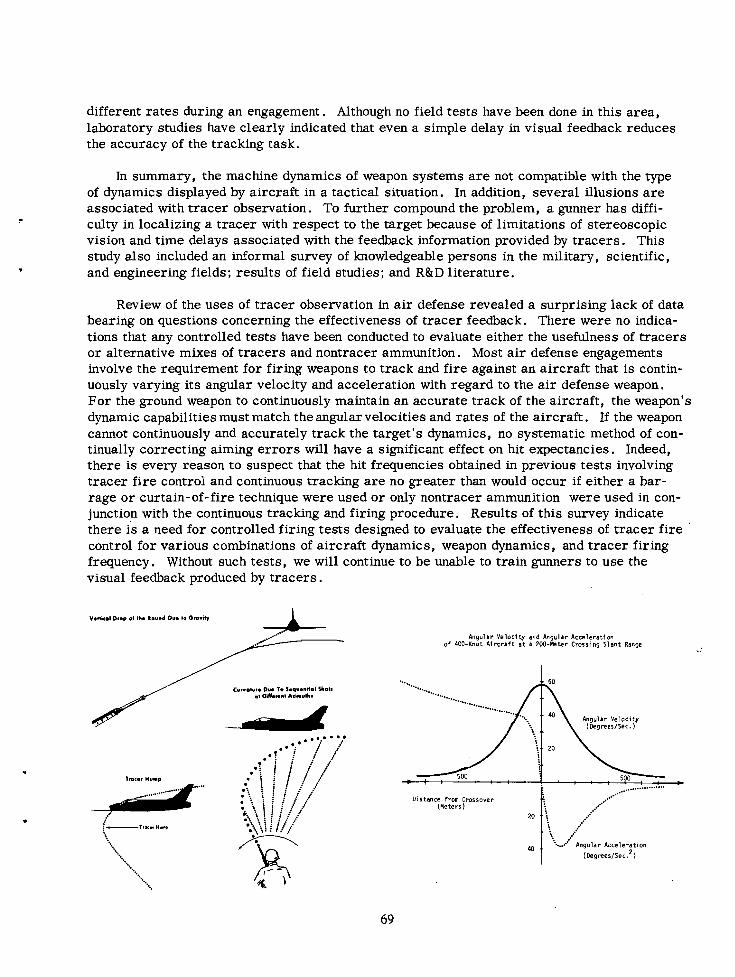
different rates during an engagement. Although no field tests have been done in this area, laboratory studies have clearly indicated that even a simple delay in visual feedback reduces the accuracy of the tracking task.
In summary, the machine dynamics of weapon systems a r e not compatible with the type of dynamics displayed by aircraft in a tactical situation. In addition, several illusions a r e associated with tracer observation. To further compound the problem, a gunner has diffi- culty in localizing a tracer with respect to the target because of limitations of stereoscopic vision and time delays associated with the feedback information provided by t racers . This study also included an informal survey of knowledgeable persons in the military, scientific, and engineering fields; results of field studies; and R&D literature.
Review of the uses of tracer observation in a i r defense revealed a surprising lack of data bearing on questions concerning the effectiveness of tracer feedback. There were no indica- tions that any controlled tests have been conducted to evaluate either the usefulness of tracers or alternative mixes of t racers and nontracer ammunition. Most a i r defense engagements involve the requirement for firing weapons to track and fire against an aircraft that is contin- uously varying its angular velocity and acceleration with regard to the a i r defense weapon. For the ground weapon to continuously maintain an accurate track of the aircraft, the weapon's dynamic capabilities must match the angular velocities and rates of the aircraft. If the weapon cannot continuously and accurately track the target's dynamics, no systematic method of con- tinually correcting aiming e r r o r s will have a significant effect on hit expectancies. Indeed, there is every reason to suspect that the hit frequencies obtained in previous tests involving tracer f ire control and continuous tracking a r e no greater than would occur if either a bar- rage o r curtain-of-fire technique were used o r only nontracer ammunition were used in con- junction with the continuous tracking and firing procedure. Results of this survey indicate there i s a need for controlled firing tests designed to evaluate the effectiveness of tracer f ire control for various combinations of aircraft dynamics, weapon dynamics, and tracer firing frequency. Without such tests , we will continue to be unable to train gunners to use the visual feedback produced by t racers .
Venkol Dr.@ ol L. Round Due lo Ororit* -L- Angular Yelocl ty and Angular Acceleration
o f 400-Knot A l rc ra f t a t a 200 -Wte r Cmrr ing Slant Range
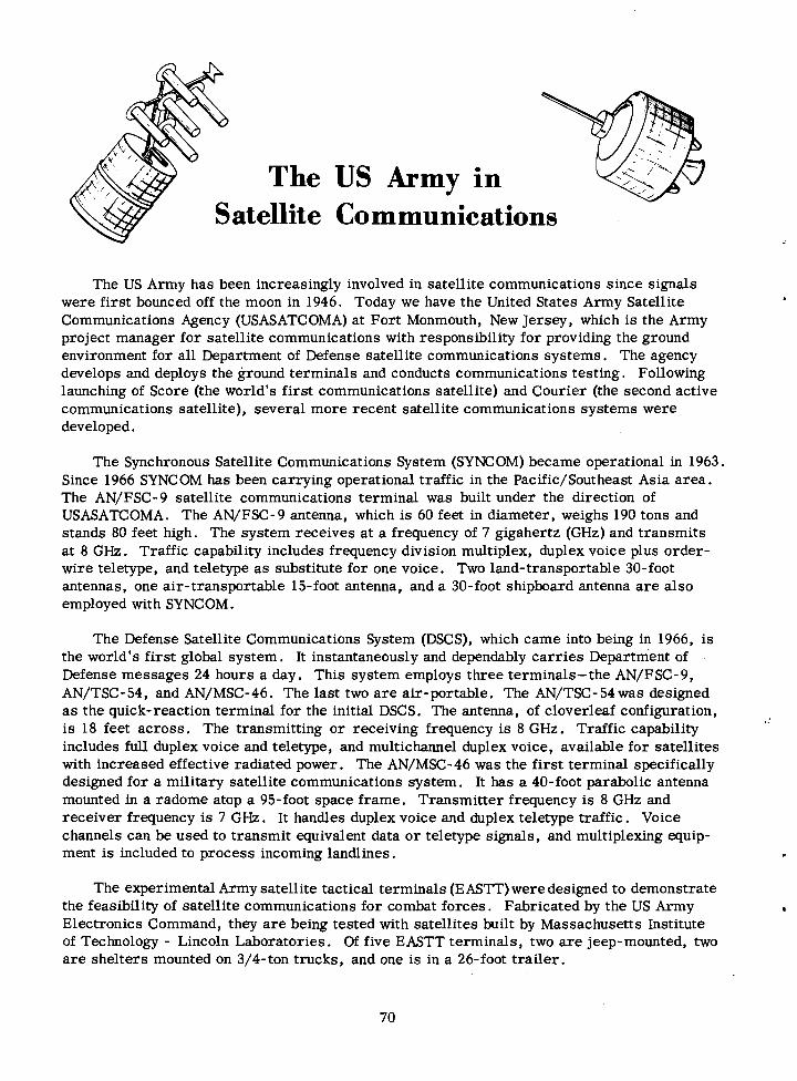
The US Army in Satellite Communications
The US Army has been increasingly involved in satellite communications since signals were first bounced off the moon in 1946. Today we have the United States Army Satellite Communications Agency (USASATCOMA) at Fort Monmouth, New Jersey, which is the Army project manager for satellite communications with responsibility for providing the ground environment for all Department of Defense satellite communications systems. The agency develops and deploys the ground terminals and conducts communications testing. Following launching of Score (the world's f irst communications satellite) and Courier (the second active communications satellite), several more recent satellite communications systems were developed.
The Synchronous Satellite Communications System (SYNCOM) became operational in 1963. Since 1966 SYNCOM has been carrying operational traffic in the Pacific/Southeast Asia area. The AN/FSC-9 satellite communications terminal was built under the direction of USASATCOMA. The AN/FSC-9 antenna, which is 60 feet in diameter, weighs 190 tons and stands 80 feet high. The system receives at a frequency of 7 gigahertz (GHz) and transmits at 8 GHz. Traffic capability includes frequency division multiplex, duplex voice plus order- wire teletype, and teletype a s substitute for one voice. Two land-transportable 30-foot antennas, one air-transportable 15-foot antenna, and a 30-foot shipboard antenna a r e also employed with SYNCOM.
The Defense Satellite Communications System (DSCS), which came into being in 1966, is the world's f irst global system. It instantaneously and dependably carr ies Department of Defense messages 24 hours a day. This system employs three terminals-the AN/FSC-9, AN/TSC- 54, and AN/MSC-46. The last two a r e air-portable . The AN/TSC- 54 was designed a s the quick-reaction terminal for the initial DSCS, The antenna, of cloverleaf configuration, i s 18 feet across. The transmitting o r receiving frequency is 8 GHz. Traffic capability includes full duplex voice and teletype, and multichannel duplex voice, available for satellites with increased effective radiated power. The AN/MSC-46 was the f irst terminal specifically designed for a military satellite communications system. It has a 40-foot parabolic antenna mounted in a radome atop a 95-foot space frame. Transmitter frequency is 8 GHz and receiver frequency is 7 GHz. It handles duplex voice and duplex teletype traffic. Voice channels can be used to transmit equivalent data o r teletype signals, and multiplexing equip- ment is included to process incoming landlines.
The experimental Army satellite tactical terminals (EASTT) were designed to demonstrate the feasibility of satellite communications for combat forces. Fabricated by the US Army . Electronics Command, they a r e being tested with satellites built by Massachusetts Institute of Technology - Lincoln Laboratories. Of five EASTT terminals, two a r e jeep-mounted, two a r e shelters mounted on 3/4-ton trucks, and one is in a 26-foot trai ler .
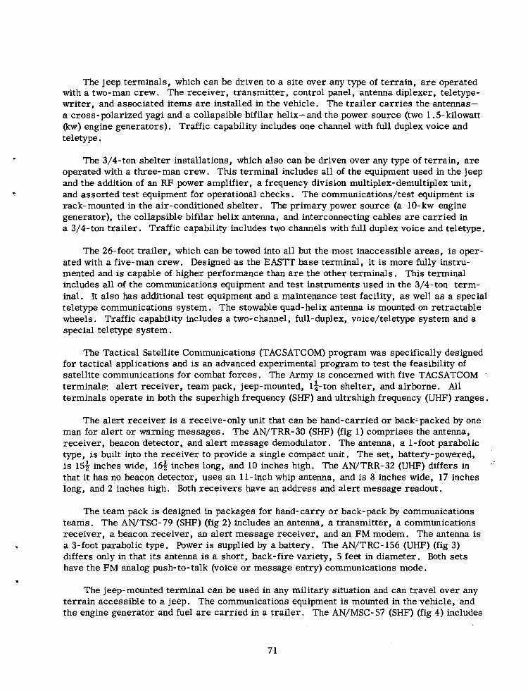
The jeep terminals, which can be driven to a site over any type of terrain, a r e operated with a two-man crew. The receiver, transmitter, control panel, antenna diplexer, teletype- writer, and associated items a r e installed in the vehicle. The trailer carries the antennas- a cross-polarized yagi and a collapsible bifilar helix-and the power source (two 1.5-kilowatt (kw) engine generators). Traffic capability includes one channel with full duplex voice and teletype.
The 3/4-ton shelter installations, which also can be driven over any type of terrain, a r e operated with a three-man crew. This terminal includes all of the equipment used in the jeep and the addition of an RF power amplifier, a frequency division multiplex-demultiplex unit, and assorted test equipment for operational checks. The communications/test equipment is rack-mounted in the air-conditioned shelter. The primary power source (a 10- kw engine generator), the collapsible bifilar helix antenna, and interconnecting cables a r e carried in a 3/4-ton trailer . Traffic capability includes two channels with full duplex voice and teletype.
The 26-foot trailer, which can be towed into all but the most inaccessible areas, is oper- ated with a five-man crew. Designed as the EASTT base terminal, it is more fully instru- mented and is capable of higher performance than a r e the other terminals. This terminal includes all of the communications equipment and test instruments used inthe 3/4-ton term- inal. It also has additional test equipment and a maintenance test facility, a s well a s a special teletype communications system. The stowable quad- helix antenna is mounted on retractable wheels. Traffic capability includes a two-channel, full-duplex, voice/teletype system and a special teletype system.
The Tactical Satellite Communications (TACSATCOM) program was specifically designed for tactical applications and is an advanced experimental program to test the feasibility of satellite communications for combat forces. The Army is concerned with five TACSATCOM terminals: alert receiver, team pack, jeep-mounted, 14-ton shelter, and airborne. All terminals operate in both the superhigh frequency (SHT) and ultrahigh frequency (UHF) ranges.
The alert receiver is a receive-only unit that can be hand-carried o r back~packed by one man for alert or warning messages. The AN/TRR-30 (SHF) (fig 1) comprises the antenna, receiver, beacon detector, and alert message demodulator. The antenna, a 1-foot parabolic type, is built into the receiver to provide a single compact unit. The set, battery-powered, i s 15* inches wide, 16 i inches long, and 10 inches high. The AN/TRR-32 (UHF) differs in ,' that it has no beacon detector, uses an 11-inch whip antenna, and is 8 inches wide, 17 inches long, and 2 inches high. Both receivers have an address and alert message readout.
The team pack is designed in packages for hand-carry o r back-pack by communications teams. The AN/TSC-79 (SHF) (fig 2) includes an antenna, a transmitter, a communications receiver, a beacon receiver, an alert message receiver, and an FM modem. The antenna is a 3-foot parabolic type. Power is supplied by a battery. The AN/TRC- 156 (UHF) (fig 3) differs only in that its antenna is a short, back-fire variety, 5 feet in diameter. Both sets have the FM analog push-to-talk (voice o r message entry) communications mode.
The jeep-mounted terminal can be used in any military situation and can travel over any terrain accessible to a jeep. The communications equipment is mounted in the vehicle, and the engine generator and fuel a r e carried in a trailer . The AN/MSC- 57 (SHF) (fig 4) includes
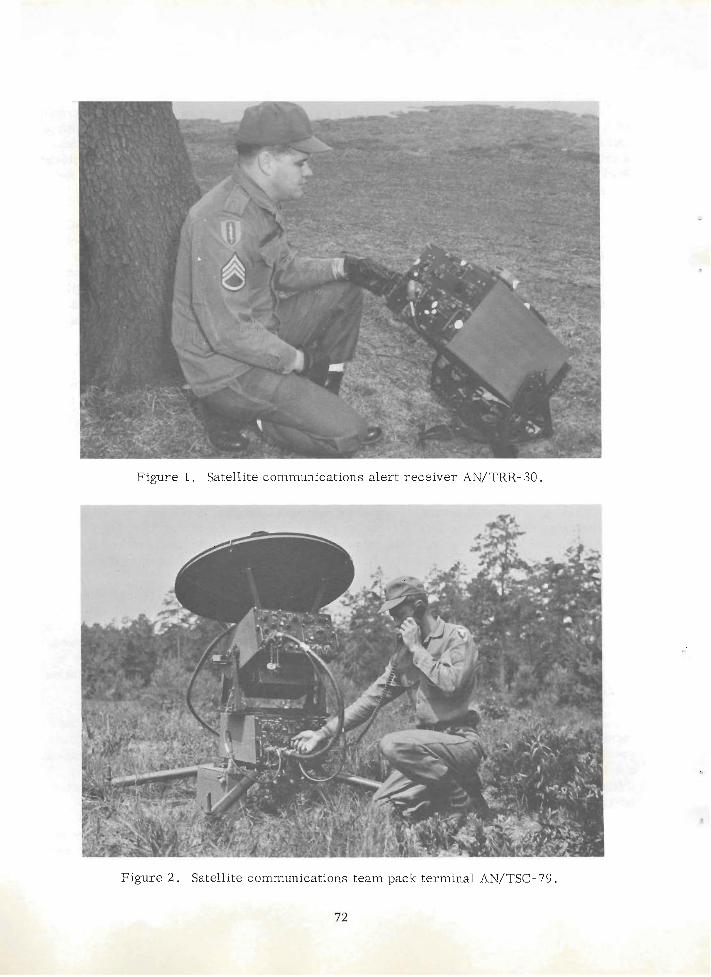
Figure 1. Satellite communications alert receiver AN/TRR- 30.
I Figure 2. Satellite communications team pack .terminal AN/TSC- 79.
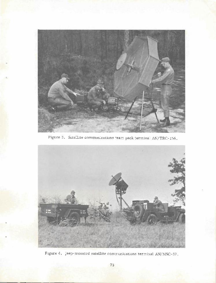
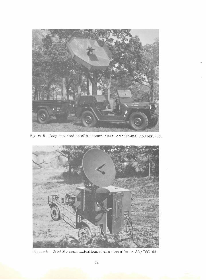
Figure 5. Jeep-mounted satellite communications terminal AN/MSC- 58.
Figure 6 . Satellite communications shelter installation nN/TSC- 80.
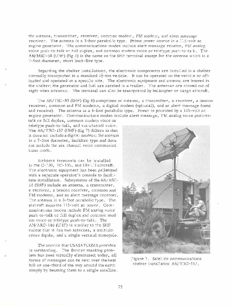
the antenna, transmitter, receiver, common modem, FM modem, and alert message receiver. The antenna is a 3-foot parabolic type. Prime power source is a 115-volt ac engine generator. The communications modes include alert message receive, FM analog voice push-to-talk o r full duplex, and common modem voice o r teletype push-to-talk. The AN/MSC-58 (UHF) (fig 5) is the same a s the SHF terminal except for the antenna whidh is a 7-foot diameter, short back-fire type.
Regarding the shelter installations, the electronic components a r e installed in a shelter normally transported in a standard l i - ton vehicle. It can be operated on the vehicle o r off- loaded and operated on a specific site. The electronic equipment and antenna a r e housed in the shelter; the generator and fuel a r e carried in a trai ler . The antennas a r e stowed out of sight when intransit. The terminal can also be transported by helicopter o r cargo aircraft.
The AN/TSC-80 (SHF) (fig 6) comprises an antenna, a transmitter, a receiver, a beacon receiver, common and F M modems, a digital modem (optional), and an alert message (send and receive). The antenna is a 4-foot parabolic type. Power is provided by a 115-volt ac engine generator. Communications modes include alert message, FM analog voice push-to- talk o r full duplex, common modem voice o r teletype push-to-talk, and six-channel voice. The AN/TRC- 157 (UHF) (fig 7) differs in that it does not include a digital modem; the antenna is a 7-foot diameter, backfire-type and does not include the six- channel voice communica- tions mode.
Airborne terminals can be installed in the C- 130, EC- 135, and UH- 1D aircraft. The electronic equipment has been palletized. with a separate operator's console to facilii tate installation. Subsystems of the AN/ASC- 14 (SHF) include an antenna, a transmitter, a receiver, a beacon receiver, common and FM modems, and an alert message receiver. The antenna is a 3-foot parabolic type. The aircraft supplies 115-volt ac power. Com- munications modes include FM analog voice push-to-talk o r full duplex and common mod- em voice o r teletype push-to-talk. The AN/ARC- 146 (UHF) is similar to the SHF except that i t has two antennas, a multiple- cross dipole, and a single vertical monopole.
I The service that USASATCOMA provides
is outstanding. The former masking prob- lem has been virtuallv eliminated: todav. all
4 .
forms of messages can be sent over thenext Figure 7 . Satellite communications
hill o r one-third of the way around the earth shelter installation AN/TRC- 157.
simply by beaming them to a single satellite.
Background Facts Related National Defense
W . R . Smedberg 111 Vice Admiral, US Navy, Retired
President, Retired Officers Association Washington, D.C.
On 28 April 1970 a small group of top officials of organizations which actively support an adequate national defense for the United States met with the President in the White House Cabinet room. I was honored to be one of that group.
The President talked for more than an hour of the particular problems bearing on our national security. This most unusual, if not unprecedented, talk to a group of mostly retired military and naval personnel, and the frankness with which he expressed his ideas, were positive proof of the trust and confidence our Commander-in-Chief places in those men and women who have given so many years of their lives to insure the security of this nation.
The President commented on trends which appear fashionable today, the viewing of patri- otism with scorn, the downgrading of those in the military services, and the efforts to cut back on our national defense. He recognized, as do many military men, that military forces and military spending a r e looked upon in some quarters a s inherently evil.
He recognized the high motives behind many of those who wish to take money from the defense budget in order to modernize ghettos, rebuild cities, and clean our polluted a i r and water. The President believes that there must be major improvement in those areas, but he said that unless this country has adequate defenses, there may be no environment, at all, to worry about in the years ahead. Therefore, he feels that there must be proper balance between the required security needs of this country and the money spent in improving those areas which must be improved.
In my happy retirement I had thought that we were maintaining our deterrent capability and therefore our security. But the sobering, even startling developments of the past few years related to us by the President, many of the details of which have been released by the Secretary of Defense, indicate that the United States is now very close to the point where its citizens must make a decision whether we a r e to continue a s a f irst rate world power or be willing to settle for second best.
The President laid the greatest s t ress on the fact that the Soviet's attitude, a s expressed repeatedly, is one of expansion, whereas that of the United States is purely defensive.
Facts which I have learned and which I want to bring to your personal attention are:
1. At the time of the Cuban crisis , the United States had an overall 10 to 1 superiority in ICBM's. Now the Soviets a re ahead in total numbers and greatly ahead in explosive power.
2 . In the older category of multi-megaton ICBMs such a s the TITAN and comparable Soviet missiles, the Soviets in 1965 had a better than 4- 1 advantage and they still maintain that position.
3 . In 1965 the United States had 880 operational MINUTEMAN missiles. The Soviet Union had nothing comparable. Today, the Soviets have over 800 such launchers operational and a projected force that could exceed 1,000 within the next two years.
4 . In 1965, the Soviets had no operational launcher for its large SS-9 missile, which can carry a 25 megaton load. Today they have 220 operational systems and 60 or more under construction. The United States has no counterpart to this system.
5. The Soviets a r e continuing work on their anti-ballistic missile (ABM) deployment in the Moscow area and presently have a total of 64 launchers in place. The United States has none.
6. In the past year the Soviets installed over 120 additional ICBM sites; the U. S. none.
7 . In the past year the Soviets built 8 new nuclear submarines with nuclear missile capability. We built none. We still have a superiority of almost 24 to 1 in nuclear subma- rines capable of delivering nuclear warheads from the sea, but, by 1975, the Soviets will not only have equalled, but at the present rate of construction will have passed our sea-based nuclear delivery capability.
8. In 1965, neither a depressed trajectory ICBM nor a Fractional Orbital Bombardment System existed in either the Soviet or U. S. inventory. Today, the Soviets have tested both configurations and may have an oper,ational version ready for deployment. The United States has developed nothing comparable to these systems.
9. In 1965, there was no development underway of a so-called Undersea Long- Range Missile System (ULMS) by either the United States o r the Soviet Union. Today, the United States is spending relatively small sums in research and development of such a system. The Soviet Union is testing a new, long-range missile for possible Naval use.
10. In 1965, the Soviet heavy bomber force consisted of slightly over 200 aircraft. The U. S. heavy bomber force strength was about 780. Today, the Soviet heavy bomber force is slightly under 200. U. S. heavy bomber strength had declined to about 550. .
These were sobering statements; in fact startling to me in both frankness and facts. Six years ago when I retired from the Navy, figures and statements such a s these were "Top Secret." This new policy of the present Administration of disclosing such facts to the American people is worthy of the attention and commendation of all of our citizens. It may be possible that a potential enemy will gain some additional knowledge, but the probability is that these facts a re known to his intelligence agencies already. They should, therefore, properly be known by all Americans. Only if each citizen is aware of the threats to our secu- rity can he support with confidence a defense adequate to guarantee our continuing security.
I think most of us around that Cabinet table were deeply impressed by the seriousness of the President. He had no cheerful smile after the first few minutes when he greeted us. We recognized that he felt the facts were grim and that he was doing his best to present them a s they appeared to him, without camouflage o r softening.
The President left no doubt that his objective is to restore and then to maintain peace, but he understands, perhaps better than any man in America today, that one does not achieve or maintain peace from a posture of weakness.
Air Defens e Control and Coordination System
The attitude toward the necessity for a i r defense, particularly of men undergoing a i r attack, is predictable-in a word, favorable. A significant portion of our defense dollar has been spent to counter a i r attack, and future obligations a r e under serious consideration. The tangible results of these efforts toward a i r defense a r e generally weapons o r weapon systems, and the publicity release dear to the heart of the average public information officer (PIO) in- cludes the picture of a surface-to-air missile dramatically silhouetted against a menacing sky. There is a related type of materiel, however, which is becoming a s important to a i r defense a s the basic weapon itself.
We refer to a i r defense control and coordination system (ADCCS) o r the older f ire distri- bution systems (FDS). The exact name is relatively unimportant- "fire control system" was used a t one time but dropped because of possible confusion with weapon-peculiar guidance systems. The operative words, in any case, a r e control, coordination, o r distribution, and the functions a r e the classic acquisition, evaluation, and dissemination of intelligence, and - commands, among all elements of the defense.
This country entered the KoreanConflict with an a i r defense control and coordination system little changed from that used in World War 11. The basic equipment of the antiair- craft operations center (AAOC) was the AN/TTQ- 1 o r AN/TTQ-2, a gridded horizontal plot- ting board on which aircraft positions were indicated by track stands displaying essential track information. Acquisition and dissemination of intelligence were entirely by voice, with plotters positioning the track stands in accordance with information received from radar sites and observation posts and tel lers broadcasting the displayed situation to the entire defense.
In the AN/MTQ- 1, introduced in limited quantity in the early 19501s, the horizontal plot- ting board and track stand of the AN/TTQ-2 were replaced by a vertical transparent plotting board and grease pencil. Plotting board, operating positions, and communications were permanently mounted in an air-conditioned operations trai ler , but the operational concept and data handling capabilities remained unchanged. However, about this same time, develop- ment was begun on the AN/MTQ-2 in an effort to achieve a greater degree of control by speeding up the data-gathering and evaluation process.
About the time the AN/MTQ-2 was being developed and evaluated, computer technology had advanced to the point where serious consideration was being given to adapting computer techniques to the problem of rapidly processing and disseminating a i r defense intelligence. This involved almost complete automation of the plotting function by displaying radar information on plan position indicators (PPI) located within the operations room (as in the AN/MTQ-2)and identifying tracks directly on the PPI by electronically generated marks (thereby overcoming a drawback of the AN/MTQ-2 where the markers were always 2 to 3 minutes behind the live PPI display). These markers, o r identity "tags, " were also displayed on other cathode- ray tubes along with pertinent suitably coded information so that the overall situation could be evaluated at a glance. Rapid dissemination of information and commands was made possible by digital coding and transmission techniques, the weapons being tied into the system by means of a f i re unit integration facility (FUIF) at each battery. For the first time, the a i r defense artillery battery was able to see the a i r situation being displayed at the Army a i r
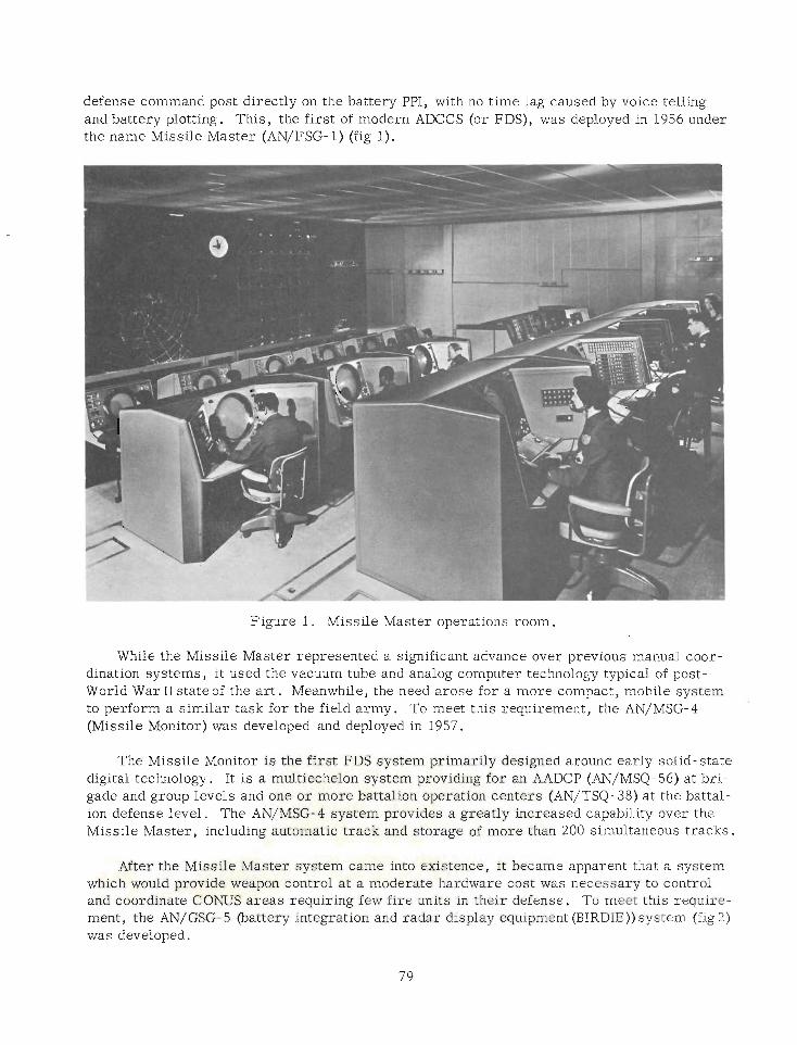
defense command post directly on the battery PPI, with no time lag caused by voice telling and battery plotting. This, the first of modern ADCCS (or FDS), was deployed in 1956 under the name Missile Master (AN/FSG- 1) (fig 1).
Figure 1 . Missile Master operations room.
While the Missile Master represented a significant advance over previous manual coor- dination systems, it used the vacuum tube and analog computer technology typical of post- World War I1 state of the ar t . Meanwhile, the need arose for a more compact, mobile system to perform a similar task for the field army. To meet this requirement, the AN/MSG-4 (Missile Monitor) was developed and deployed in 1957.
The Missile Monitor is the first FDS system primarily designed around early solid- state digital technology. It is a multiechelon system providing for an AADCP (AN/MSQ-56) at bri- gade and group levels and one o r more battalion operation centers (AN/TSQ- 38) at the battal- ion defense level. The AN/MSG-4 system provides a greatly increased capability over the Missile Master, including automatic track and storage of more than 200 simultaneous tracks.
After the Missile Master system came into existence, it became apparent that a system - which would provide weapon control a t a moderate hardware cost was necessary to control
- and coordinate CONUS areas requiring few fire units in their defense. To meet this require- ment, the AN/GSG- 5 (battery integration and radar display equipment (BIRDIE)) system (fig 2) was developed.
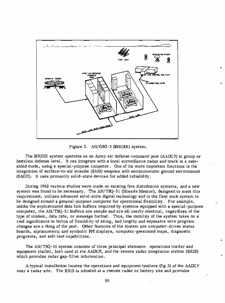
Figure 2 . AN/GSG- 5 (BIRDIE) system.
The BIRDIE system operates a s an Army a i r defense command post (MDCP) at group o r battalion defense level. It can integrate with a local surveillance radar and track in a rate- aided mode, using a special-purpose computer. One of its more important functions is the integration of surface-to-air missile (SAM) weapons with semiautomatic ground environment (SAGE). It uses primarily solid- state devices for added reliability.
During 1962 various studies were made on existing f i re distribution systems, and a new system was found to be necessary. The AN/TSQ-51 (Missile Mentor), designed to meet this requirement, utilizes advanced solid-state digital technology and is the first such system to be designed around a general-purpose computer for operational flexibility. For example, unlike the sophisticated data link buffers required by systems equipped with a special-purpose computer, the AN/TSQ-51 buffers a r e simple and a r e all nearly identical, regardless of the type of modem, data rate, o r message format. Thus, the mobility of the system takes on a real significance in terms of flexibility of siting, and lengthy and expensive wire program changes a r e a thing of the past. Other features of the system a r e computer-driven status boards, alphanumeric and symbolic PPI displays, computer-generated maps, diagnostic programs, and self-test capabilities.
The AN/TSQ- 51 system consists of three principal elements: operations trai ler and equipment trai ler , both used at the MDCP, and the remote radar integration station (RRIS) which provides radar gap- filler information.
A typical installation locates the operations and equipment trai lers (fig 3) of the MDCP near a radar site. The RRIS is situated at a remote radar o r battery site and provides
80
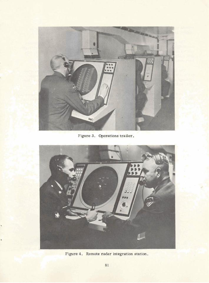
Figure 4. Remote radar integration station,
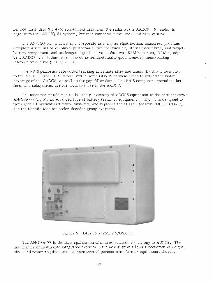
remote track data (fig 4) to supplement data from the radar at the AADCP. No radar is organic to the AN/TSQ-51 system, but it is compatible with most military radars.
The AN/TSQ- 51, which may incorporate a s many a s eight tactical consoles, provides complete a i r situation displays; performs automatic tracking, status monitoring, and target- battery assignment; and exchanges digital and voice data with SAM batteries, RRIS's, adja- cent AADCP's, and other systems such a s semiautomatic ground environment/backup interceptor control (SAGE/BUIC).
The RRIS performs rate-aided tracking at remote sites and transmits this information to the LMXP. The RRIS is required in some CONUS defense areas to extend the radar coverage of the AADCP, a s well a s for gap-filler data. The RRIS computer, consoles, buf- fers, and subsystems a r e identical to those in the AADCP.
The most recent addition to the Army inventory of ADCCS equipment is the data converter AN/GSA-77 (fig S) , an advanced type of battery terminal equipment (BTE). It is designed to work with all present and future systems, and replaces the Missile Master FUIF in CONUS and the Missile Monitor coder-decoder group overseas.
Figure 5. Data converter AN/GSA- 77.
The AN/GSA- 77 is the first application of microelectronic technology to ADCCS. The use of microminiaturized integrated circuits in the new system allows a reduction in weight, size, and power requirements of more than 90 percent over former equipment, thereby
permitting the data converter to be mounted ipslc@existing battery control shelters. As a result, considerable equipment, including a tGck, a shelter, air-conditioning units, a gen- erator, and a trailer, needed to support the old system's electronics is eliminated. Thanks to high-reliability factors inherent in mif!roelectronic integrated circuits, the system's built-in self-test capability, and throwaway-at-failure maintenance philosophy, a soldier with only a basic technical knowledge can normally locate a faulty circuit, replace it, and have the system back in operation within minutes.
The extensive use of microminiaturization, the throwaway concgt of maintenance, and system design that fncorporates automatic o r semiautomatic self-testing will unquestionably be major considerdtions in the development of future ADCCS. Numerous studies by industry and the military establishment have shown that proper application of these considerations dramaticdly lowers the total life-cycle cost of materiel, and this finding has been indorsed by Department of the Army. Ea-hples of this new trend a r e the AN/TSQ- 75 ADCCS (expect- ed R&D contract later this ygiQr), Safeguard, and SAM- D fire coordination equipment.
We may expect to &&! air defense materiel in the future that will detect and identlfy aerial&:argets, evaluate the overall a i r threat on a second- to- second basis, consider the defense situation to include out- of- action batteries and ammunition on hand, select one o r more fire units to engage and then guide defensive missiles over a t least part of their trajectory, disseminate warning of nuclear engagement, and evaluate and record results of engagement all without intervention of a single man (except for observation of the battle and occasional override of a machine decision). The system will examine itself for proper operation and automatically correct malfunctions by switching in standby circuits while the defective item is being replaced by maintenance men.
If machines a r e to actually fight the a i r defense battle, a r e soldiers becoming obsolete? Advances in materiel a r e being made a t the cost of a fantastic complexity of detail. "Service of the piece" now demands a new order of intelligence, training, and dedication from the men who use and maintain it. As always, the tools of war a r e no better than the men behind them, and the soldier, in the last analysis, is the one indispensable element.

FDS -Who Needs It ? Lieutenant Colonel Roscoe H , Munme
US Army Combat Developments Command Air Defense Agency
The opinions expressed herein are tbose of the author and do not reflect official positions of any governmental or military agency of the United States.
The pendulum swings again toward economizing, and the first candidate for fiscal axes is the favorite whipping boy-the Armed Forces. Let's face it, we a r e a very expensive piece of the action. Nonetheless, the services do get cut and the Army takes its lumps along with the others for its share; and allocations a r e made, we hope, according to the real priority needs. In any event, the dust settles and the arudous task begins-the task of doing the best we can with what we have.
Air defense artillery must naturally put first things first and relegate nice-to-have i t e m to second place or, when things really get tight, forget 'em. Our mission is to clobber the bad guys before they can hurt the grunt on the ground. After all is said and done, it 's the grunt on the ground who wins o r loses the war-propaganda of other branches and services notwithstanding. It's the grunt on the ground who takes and holds the objectives-who ulti- mately wins the war-and he must be able to focus his attention toward that goal. Accepting that, we must protect him from ai r attack while he's popping snipers, busting bridges, build- ing roads, o r whatever is his bag on any particular day. We must also protect his beans, bullets, and benzine and the people who get these goodies up to him.
Sounds like quite a chore, doesn't it? You h o w it! We h o w airpower can't win the war for either side, but it sure helps, or makes it rough, depending on who is on the receiving end. We have to detect, identify, and destroy hostile aircraft before our combat power is reduced to an unacceptable level. We can do a pretty fair job of it too because "we t ry harder" a s the saying goes. Air defense artillery maintains a wartime footing all the time. To do our part we must have the right gear. We now have a i r defense weapons that a r e fairly effective and a r e tied together by sophisticated control systems. It causes potential aggressors to soberly reflect before they start any real hanky-panky. Even so, we need improvements if we a r e to keep abreast of the threat. Improvements cost $$$, and $$$ a r e getting a s scarce a s hen's teeth. Soooooooo, concentrate on the must-have items.
We need to: We have:
Detect
Identify
Eyeballs (good but short range) Radar (good but needs improvement)
Eyeballs (good when trained but still short range)
IFF (better than nothing but needs much improvement)
Destroy Weapons (good but require improve- ment to stay ahead of the threat)
"Whoa, Clyde," you say, "what about FDS?" (fire distribution systems to the uninformed). "Isn't that what this is all about?"
"Yes indeed, " I reply, "but who needs it?"
"But, but, but, " you say, "lookit BIRDIE, lookit MSG-4, or TSQ-38, or TSQ-51, and all them good things! Do you mean to sit there like a lump and tell me that the billions of $$$ and the kiloman years of development and production, not to mention the megaman hours spent in operating and maintaining that stuff was wasted?"
"No, " I respond to this emotional outburst, "not entirely. "
"Aha! " you chortle, "then you admit we need them! "
"Wrong again, " I calmly reply.
"Well for TACSOP's sake, what exactly do you mean?"
"Well," I smugly reply, "those things kept a lot of people in business-that's good. They took resources that could have been used to improve our detection, ID, and destruction capability-that's bad. Worst of all, they a r e now competing with our needed improve- ments-that's d----d bad!"
"OK, Mr. Smarty, " you retort, "then why in h--1 did we try to get them to start with? I'll tell you why so you don't make an ass of yourself in public! We need them to efficiently dis- tribute costly a i r defense fires to prevent wasting missiles on overkilling one intruder while another comes through without being engaged. We also need them to prevent the accidental clobbering of our friends in blue. We also need them to prevent the accidental triggering of a nuclear war. How about that? ! ! "
"You're getting emotional again," I respond. Then I come back, "First, overkill or under- kill. We a r e not so fat with systems having so much overlap that we have to worry about overkill, and the systems that might simultaneously engage a target can be directed by simple SOP. Anyway, until SEKP is essentially unity, more systems going after a bad guy just increase the probability of getting him."
"And underkill?"
"SOP, my lad, SOP. We've been doing it for years under the guise of 'emergency measures' when the AADCP poops out. In fact, each fire unit has his PTL with priorities for engagement already spelled out in good old SOP. "
"Yeah, but how about friendlies?" you come back slyly. "Those radars of yours can't tell a MIG from a THUD or a TUPOLEV from a SPAD. "
"So true," I sigh. "Right now we have IFF, for what it's worth. But we can easily establish flight levels, maneuvers, and approaches for friendly aircraft to follow so that, when used in conjunction with IFF, the BCO can be pretty darned sure about who is up in the sky."
"Maybe, " you muse (the simplicity of this approach astounds you), "but what if the IFF isn't working, o r the guy forgot to turn it on, or maybe he forgot the maneuver, o r maybe the IFF is compromised?"
"Good points all, " I agree. "If you were the pilot, would you forget?"
"Of course not!" you snap. "I would remember those items if nothing else!"
"Makes sense. The average guy would, and our fly jockeys a r e a shade above average-or so they claim. That leaves compromise of failure. First off, let's just ask 'em to ACT friendly. Let the high-performance jobbiks come back above, say, 10,000 feet and squawk IFF. Maybe an IFF fails, but a r e ALL the IFF'S in a flight gonna fail at the same time? Not too likely. Then too, even if they all fail o r a r e compromised, when they a r e above 10,000 feet, even the USAF long range sensors can see them and, if they a r e friendly, they can tell us. "
"How?"
"Early warning broadcast, Boy, just like always. "
"But how about preventing a nuclear accident?"
"Aw, c'mon now, " I chide, "when's the last time you had a TPI? What did you have to do in order to shoot?"
"I see what you mean. " (You're more tractable now. ) "It's quite a rigamarole, isn't it?"
"Yes indeed, " I agree, "and all of your OK's , etc . , came by voice, .didn't they?"
"Yes, by golly, " you enthuse, "the whole d- - - -d shebang was by voice! But. . . . " "But what?" I prompt.
"But how is the ADA commander gonna run the show?" 1 "With logic, practicality, and commonsense, Son. That's why he's where he is. He's got it. He plans the defense, issues movement orders, passes alert and warning information, trains his people, and expects YOU to do your job. "
"But without a big presentation of the whole shmear, how's he gonna tell me who to shoot at , and when?"
"He already has, Son, in his SOP. He'll issue periodic changes via RATT or voice if it's gotta be speedy-otherwise he'll write. 'Course that old commo has to be survivable, simple, reliable, and secure. "
"But look a t all the things we have now-computers with all that capability-be a shame to waste it. We can have Round Robin, data exchange, and all that good stuff and, percentage-
I wise, it costs very little. "
86 I

(You're grasping at straws now. )
"That's right," I say condescendingly. "Prove you - need it. Sure, it's nice to have, but prove you need it! Also, a few percent-let's say 2 percent, of about $100,000,000 is more than I spend on booze in a lifetime and it would buy a lot of Redeye, Vulcan, Chaparral, et al . Best let the luxuries die gracefully. "
"All right, all right, ALL RIGHT! ! I get your point! But hear this, the USAF pops the AD whip and they'll never let you get away with it! This old Army will really have to get up on it's hind legs and say it like it is before action will be taken to change the JCS and DOD Pubs! "
"Yep," I reply.
Abandoned Nike Missile Base Becomes School in Small Town
When the Nike Hercules missile base near Gardner, Kansas, was phasing out recently, the Gardner- Edgerton- Antioch School District in that small community had something to be be pleased about.
The school district, so crowded for space that classes a r e being held in such strange places a s church basements and apartments, began petitioning for the base when the Pentagon announced in 1968 that it would be one of the 22 bases to be closed.
Though several other organizations wanted the facility, the erstwhile defense base is now securely in the hands of the school board.
"I don't think anyone in the community doubts we can build a fine junior high school from the Nike facilities," said the school superintendent, while discussing the transformation from a defense center against enemy attackers to an education center.
Plans aren't final, but the junior high principal elaborated on what might occur. "The radar tower, " he said, "could be a telescope platform for science classes. The command building-with thick concrete walls-could do double duty as a library and tornado shelter. The messhall and one of the barracks could be converted to a cafeteria and administration building, respectively. "
Looking to the future, the principal predicted that the launching apparatus, which is underground, might be developed into elementary classrooms for the school system.
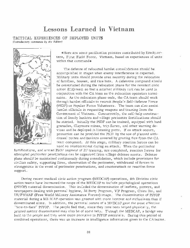
Lessons Learned in Vietnam TACTICAL EXPERIENCES OF DEPLOYED UNITS (Introductory comments by tbe Editor)
l Here are some pacification pointers contributed by Headquar - ters, First Field Force, Vietnam, based on experiences of units within that commando
The defense of relocated hamlet consolidations should be accomplished in stages when enemy interference is expected. Military units should provide area security during the relocation of families, houses, and rice huts. A defensive compound should be constructed during the relocation phase for the resident civic action (CA) team so that a smaller military unit can be used in conjunction with the CA team as the relocation operation termi- nates. As the relocation phase ends, the CA team should work through hamlet officials to recruit People's Self- Defense Force (PSDF) or Popular Force Volunteers. The team can also assist hamlet officials in requesting weapons and training from the Government of Vietnam. Concurrently, the self- help construc- tion of family bunkers and village perimeter fortifications should be started. Initially the PSDF can be trained, equipped with hand grenades, Claymore mines, trip flares, and other warning de- vices and be deployed in listening posts. If an attack occurs, protection can be provided the PSDF by the use of planned with- drawal routes and bunkers covered by grazing fire from the CA team compound. At this stage, military reaction forces can be used as reinforcement during an attack. When the perimeter
fortifications, and armed PSDF segment of PF training, a re completed, reaction forces for attempted perimeter penetrations can be organized from village defense assets . Defense plans should be maintained continuously during consolidation, which include provisions for civilian safety, supporting fires, observation of the perimeter, withdrawal of forces to strongpoints in the event of perimeter penetrations, and counterattack or reaction force support.
During recent medical civic action program (MEDCAP) operations, 4th Division civic action teams have increased the scope of the MEDCAP to include psychological operations (PSYOP) material dissemination. This included the dissemination of leaflets, posters, and newspapers dealing with personal hygiene, 3d Party Program, VIP Program, Chieu Hoi, and US/FWMAF (Free World Military Assistance Forces) image. The dissemination of PSYOP material during a MEDCAP operation was greeted with more interest and enthusiasm than if disseminated alone. In addition, the personal nature of a MEDCAP gave the most effective "face-to-face" PSYOP. The people feel that, since they have been helped physically, the printed matter disseminated may also be of some help. Through the MEDCAP, a bridge was built to the people and they were more receptive to PSYOP materials. During this period of combined operations, there was an increase in intelligence information given to the CAteams.
The surgeons of the 173d Airborne Brigade have been very active in local MEDCAP missions. In villages and hamlets regularly visited on a weekly o r 10- day schedule, they have observed that many minor illnesses o r diseases common to the Vietnamese people have almost disappeared. Thus, for maximum benefit, MEDCAP missions should be held regu- larly in key hamlets o r villages rather than at random sites at random times which allows no medical "followup. "
A tremendous psychological impact i s made when homes destroyed by Viet Cong ter ror- ists a r e immediately rebuilt. A policy of "quick rebuild" has been established in IFFV (First Field Force, Vietnam), DEPCORDS (deputy civil operations revolutioning development sup- port), using FWMAF and ARVN (Army, Republic of Vietnam) resources. It is designed to render timely and humanitarian assistance by bringing rapidly to bear materials and relief funds to those localities where homes have been destroyed, families torn apart, and bread- winners killed o r incapacitated. The people so affected a r e quickly made to see that their government cares about them and does something to relieve them in their adversity. These people, a s a general rule, never like to leave their land and crops, and when "quick rebuild" is accomplished, the loss and trauma for them a r e lessened.
Remarkable results have been attained in Ninh Thuan Province in reducing the number of desertions of readiness defense (RD) cadre. By applying the following actions, Ninh Thuan reduced its desertion ra te from 6.9 percent in September 1968-the highest in I1 Corps-to 1 percent at present:
@Development of RD awareness among province and district chiefs.
@Institution of local measures, such a s unannounced inspections of RD cadre; deduction of pay and/or confinement a s punishment for AWOL's; establishment of mobile checkpoints at strategic locations to check cadre leaving their teams; making cadre available for the draft after the second AWOL; and building team morale; i. e . , providing for personnel services and visiting teams at least once a month.
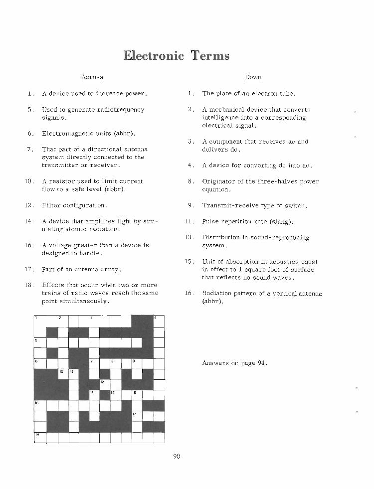
Electronic Terms
Across Down
1. A device used to increase power.
5. Used to generate radiofrequency signals.
6. Electromagnetic units (abbr).
7 . That part of a directional antenna system directly connected to the transmitter o r receiver.
10. A resistor used to limit current flow to a safe level'(abbr).
12. Filter configuration.
14. A device that amplifies light by sim- ulating atomic radiation.
16. A voltage greater than a device is designed to handle.
17. Part of an antenna array.
18. Effects that occur when two or more trains of radio waves reach the same point simultaneously.
1. The plate of an electron tube.
2 . A mechanical device that converts intelligence into a corresponding electrical signal.
3. A component that receives ac and delivers dc.
4 . A device for converting dc into ac .
8. Originator of the three- halves power equation.
9. Transmit-receive type of switch.
11. W s e repetition rate (slang).
13. Distribution in sound-reproducing system.
15. Unit of absorption in acoustics equal in effect to 1 square foot of surface that reflects no sound waves.
16. Radiation pattern of a vertical antenna (abbr) .
Answers on page 94.
Reader's Corner
CURRENT BOOKS AM) ARTICLES OF MILITARY INTEREST
This list i s published to draw attention to wortbwbile and infomative books andarticles in other publications. We realize that not all items will be available to all readers. Our motive is to be helpful to as many readers as possible,
The content of these publications does not necessarily represent the opinion of tbe U S Amy Air Defense School.
-Editor
BOOKS
Automotive Fundamentals by Ernest A. Venk. American Technical Society, Chicago. This book is in itself a complete course in automotive mechanics.
From Karl Marx to Mao Tse- Tung by Henri Chambre . Kenedy, New York. "This work contains an exposition, analysis, and synthesis of the main tenets and principal developments of Communist theory from Karl Marx to the present time."
My 15 Months in Government in the Congo by Moise Tshombe. University of Plano, Plano, Texas. "He writes of his aspirations for Black Africa, his estimate for the oldand his distaste for the dictatorship of the new colonialism, his respect for, but not reliance on, tradition in guiding his people for the long struggle ahead. "
Egypt: Military Society by Anouar Abdel Malek. Random House, New York. "This book deals specifically with the people of Egypt - the national movement, and the economic and social transformation in relation to the ideological struggle. "
The Long War; Israel and the Arabs Since 1946 by J. Bowyer Bell. Prentice Hall, Englewood Cliffs, New Jersey. "The bloody history of Arab-Israel relations is seen a s a single military operation that, in continuity, intensity and complexity, is second only to the Thirty Years' War. "

Computer- Oriented Mathematics by Ladis D. Kovach. Holden-Day, San Francisco. "The main purpose of this book is to show how mathematics has bridged the gap between the human and the machine. "
God Exists by Thomas Barrosse. University of Notre Dame Press, Notre Dame, Indiana. The author describes the development of the concept of God from the early primitive gods to the present monolithic concept of God.
Inventor's Handbook by Terrence W. Fenner. Chemical Publishing Co., New York. "Highly informative and conversational in style, Inventor's Handbook has two unique and much sought after features: A l is t of companies, indexed as to the type of product they make, that buy inventions o r manufacture them under license, and names of companies willing to finance inventions. "
Combat Leadership by The Infantry School. For t Benning, Georgia. "This pamphlet presents the method of instruction used at the US Army Infantry School in teaching combat leadership to the small unit commander. "
Basic Microwaves by Bernard Berkowitz . Hayden Book Co . , New York. "This comprehensive text develops a clear understanding of the principles underlying modern microwave technology. "
An American Dilemma; the Negro Problem and Modern Democracy by Gunnar Mydral. Harper and Row, New York . "One of the best political commentaries on American life that has ever been written because it places i ts discussion of politics in a well-rounded social science setting."
The Role of the Army in the Oxford, Mississippi, Incident by U.S. Dept of the Army. Office of Chief of Military History, Pentagon. "This is a historical report on the Army's role in the integration of the University of Mississippi, 1962- 1963."
Fabian Freeway: High Road to Socialism in the USA, 1884- 1966 by Rose L. Martin. Western Islands, Boston. "This fascinating story shows how a little band of polite revolutionaries se t out deliberately years ago to wreck the British Empire from within and to reduce the United States to a shambles, all in the name of social reform and human welfare."
Bird; the Christmastide Battle by S. L . A. Marshall. Cowles, New York. "How well does today's American fighting man stand up in a battle against overwhelming odds? The answer is found in Bird, the detailed account of such a battle." -
ARTICLES
"Berlin; On Both Sides of the Wall, " Howard Sochurek, National Geographic Uanuary 1970), pp. 1-47. Both the eastern and western sections of Berlin a r e included a s the author presents in word and picture this story of contrasts.
"New Cities: A Look at the Future," U.S. News & World Report (January 26, 1970), pp. 64-65. "Is there an alternative to piling more people into troubled urban areas? Officials from Vice President Agnew down say, 'Yes - new cities. ' A plan to build them is taking shape. "
"Computer- Aided Design, " Russell M . Narahara, Space/Aeronautim (December 1969), pp. 56-64. - -
"Design is an iterative process of trying, learning, and trying again. ~ f i t were not, computer-aided design would be an older, more familiar discipline. Design being what it is, a really useful designer's computer must be capable of continuous conversational inter- action. That's what has been so hard to get. "
"Military Forces in the War on Hunger, " Alan L. Forbes, Military Review (January 1970), pp. 41-50. "Consideration should be given to assigning responsibilities to the US Army to join with other agencies of the Federal Government to provide national leadership to US participation in the war on hunger in developing countries of strategic importance to the United States. "
"The Middle East, " Current History (January 1970), entire issue. "In this issue seven authors examine the problems of the nations of the turbulent Middle East."
"The Officer Evaluation ~xaminatio'n: A Proposal," Edward J . Laurence, Military Review (January 1970), pp. 51-55. "An officer evaluation examination, if properly constructed and administered, may break the subjective and biased deadlock caused by the current evaluation system based on the efficiency report. "
"A Defense Against Technology, " Nicholas E . Golovin, Astronautics & Aeronautics (December 1969), pp. 20-23. "TO protect the public against potentially harmful new technologies, he argues, an industry must f irst prove a product o r process harmless before exploiting it ." "The Question of Changing the U. S. Electoral System, " Congressional Digest (January 1970), entire issue. This issue discusses the origins of the present electoral system, its constitutional basis, how the system operates, the main proposals before the 91st Congress, action to date, and a pro and con discussion concerning the direct election of the President.
"Vietnamization: Priority Program, " Melvin R. Laird, Army Digest (January 1970), pp. 21-25. Secretary Laird explains what the Viemamization of the war will do and how he hopes to accomplish it.
"The Responsibility to Write, " J . W . Hammond, Jr . Marine Corps Gazette (January 1970), pp. 27-30. This author, in trying to encourage officers to contribute to military journals and become proficient in military writing, tells why military people should write, what to write, and how to write.

"Red China's Nuclear Might, " Niu Sien- Chong, Ordnance (January- February 1970), pp . 399-401. "Their rapid development of atomic weapons, begun in 1953, shows that the Chinese Communists have the scientific knowledge and technical capability to build a large and deadly modern arsenal. "
ANSWERS TO CROSSWORD PUZZLE:
Across Down - 1. Amplifier. 1. Anode.
5. Oscillator. 2. Pickup.
6. EMU. 3. Fil ter .
7. Exciter. 4. Inverter.
10. PR. 8. Child.
12. Pi. 9. TR.
14. Laser. 11. Rep rate.
16. Overload. 13. Wow.
17. Bay. 15. Sabin.
18. Interference. 16. Ornni.
Readers a re invited to submit for publication articles and informative notes that a re of profes- sional interest to the air defense artilleryman. Articles should be current and forthrightly stated and should relate to some aspect of what air defense units in the field a re doing to accomplish their mission, particularly in the technical and tactical areas'. Miscellaneous articles expressing either technical or nontechnical ideas that may be of value to a i r defense will also be considered for
Direct communication to the editor is authorized:
Office of Doctrine Development, Literature, and Hans US Army Air Defense School P. 0. Box 5600 Fort Bliss, Texas 79916

Aircraft Recognition
The next tbree pages contain 24 silhouettes of various types of aircraft printed on beavy stock. On the back of eacb i s identification information. Cut out the cards along their borders and you have 24 flash cards that can be used in aircraft recognition training. As a service t o our readers, Air Defense Trends will continue to print card pictures of different, currently employed military aircraft,
Army, Fort Bliam, Texas