u.s. army armament research and ... a typical laminated structure of alternating layers of steel and...
TRANSCRIPT

AVVAJ44 ■MCAL LIBRARY
5 0712 01017494 3
AD/? fM Z?7 AD-E401 216
TECHNICAL REPORT ARSCD-TR-83016
INTRODUCTION TO COMPOSITE MATERIALS
YOUNG SHIK SHIN
AUGUST 1984
U.S. ARMY ARMAMENT RESEARCH AND DEVELOPMENT CENTER FIRE CONTROL AND SMALL CALIBER WEAPON SYSTEMS LABORATORY
DOVER, NEW JERSEY
APPROVED FOR PUBLIC RELEASE: DISTRIBUTION UNLIMITED.
The views, opinions, and/or findings contained in this report are those of the author(s) and should not be construed as an official Department of the Army position, policy, or decision, unless so designated by other documentation.
The citation in this report of the names of commercial firms or commercially available products or services does not constitute official endorsement by or approval of the U.S. Government.
Destroy this report when no longer needed. Do not return to the originator.

UNCLASSIFIED SECURITY CLASSIFICATION OF THIS PAGE (When Dete Entered)
REPORT DOCUMENTATION PAGE READ INSTRUCTIONS BEFORE COMPLETING FORM
1. REPORT NUMBER
Technical Report ARSCD-TR-83016
2. OOVT ACCESSION NO 3 RECIPIENT'S CATALOG NUMBER
4. TITLE (and Subtitle)
INTRODUCTION TO COMPOSITE MATERIALS
5. TYPE OF REPORT A PERIOD COVERED
6 PERFORMING ORG. REPORT NUMBER
7. AUTHORS;
Young Shlk Shin
8. CONTRACT OR GRANT NUMBERS«)
9. PERFORMING ORGANIZATION NAME AND ADDRESS
ARDC, FSL Armament Division DRSMC-SCA-W (D) Dover, NJ 07801-5001
10. PROGRAM ELEMENT PROJECT, TASK AREA ft WORK UNIT NUMBERS
Project 5K78-04-001
11. CONTROLLING OFFICE NAME AND ADDRESS
ARDC, TSD STINFO Div DRSMC-TSS (D) Dover. NJ Q78Q1^QQ1
12. REPORT DATE
August 1984 13. NUMBER OF PAGES
56 14. MONITORING AGENCY NAME ft ADDRESS^/ different from Controlling Office) 15. SECURITY CLASS, (of thim report)
Unclassified »5«. DECLASSIFICATION/DOWNGRADING
SCHEDULE
»6. DISTRIBUTION STATEMENT (of thle Report)
Approved for public release; distribution unlimited.
17. DISTRIBUTION STATEMENT (of the ebetract entered In Block 20, ft different from Report)
18. SUPPLEMENTARY NOTES
19. KEY WORDS (Continue on revetae aide if neceaaary and Identify by btock number)
Boron/Aluminum Composite material Severe environmental stability- Elevated temperature strength Mechanical properties
Fatigue Fibers Matrix Reinforcement Notch toughness
20. ABSTRACT (Conttoum en. revere» ate* ff n+x+rnnmty —*d Identity by block number)
Advanced composite materials are light, stiff, and extremely strong, but suffer poor transverse strength and high price. Additional requirements for strength at elevated temperatures and stability under severe environ- mental conditions are satisfied by increasing use of metal matrix materials. Two ways to increase the composite strength is by the use of larger diameter filaments and by heat treating aluminum alloy matrix.
(cont)
DO/, Fr„M73 EDITION OF » MOV 65 IS OBSOLETE UNCLASSIFIED
SECURITY CLASSIFICATION OF TNIS PAGE (When Dmtm Entered)

TNr.T,ARSTFIED SECURITY CLASSIFICATION OF THIS PAGE(lWi«n Dmtm Entand)
Block 20. Abstract (cont)
Advanced composites are used mainly as panels or structural members in space vehicles or aircraft; a lot of new development work is required before com- posites can be used for machined parts.
Subjects covered in this report are general information on reinforcements, interface and bonding, micromechanics, consolidation processes, mechanical properties of composite materials, improved mechanical properties, and applications.
SECURITY CLASSIFICATION OF THIS PkGECWhan Data Entarad)

CONTENTS
Page
Introduction 1
Reinforcement 2
Interface and Bonding 2
Types of Interface 2 Bonding in Composites 3 Mechanical Aspects of the Interface 4
Micromechanics
Introduction 5 Density of Composites 5 Composite Stresses and Strains 6 Rule of Mixture 7 Strength 8
Consolidation Processes 9
Diffusion Bonding 10 Plasma Spray Bonding 11 Electroforraing 11 Liquid Metal Infiltration 11 High Energy Rate Forming 12 Hot Rolling Bonding 12
Mechanical Properties of Composite Materials 12
Strength 12 Tensile Properties 16 Compression 19 Impact 19 Elevated Temperature Tensile Strength 20
Improved Mechanical Properties 21
Introduction 21 Improved Filaments 21 Improved Composites 21
Applications
Introduction 23 Examples of Applications 24 Cost 24 Further Applications 24

References
Distribution List
Page
27
49
1 I

TABLES
Page
1 Filament properties 29
2 Boron type filament properties 29
3 Typical fiber properties 29
4 Typical strengths of unidirectional composites in MPa 30
5 Strength parameters in stress space for unidirectional composites 30
6 Strength parameters in strain space for unidirectional composites (dimensionless) 30
7 Tensile properties of boron/aluminum and boron/titanium composites 31
8 Properties of 50 v/o boron/aluminum 31
9 Properties of 50 v/o Borsic/Ti 31
10 Axial tensile strength of 5.6 mil B/Al 32
11 Axial tensile strength of 5.7 rail Borsic/Al composites 33
12 Transverse tensile properties of 5.6 mil B/Al 34
13 Transverse tensile properties of 5.7 mil Borsic/Al 35
14 Axial tensile strength of 48 v/o 5.6 mil B/6061 Al Composites 36
iii

Figures
Page
1 Schematic of principal bond types 37
2 Typical stress-strain relations of fiber, matrix and composite 37
3 Composite materials fabrication process 37
4 A schematic diagram of the winding apparatus 38
5 Schematic diagram of the apparatus for vacuum casting 39
6 Composite billet for high energy rate forming composite plates 40
7 Hot-roll bonding 41
8 On-axis positive and negative shears 41
9 Uniaxial longitudinal tensile and compressive tests 41
10 Typical stress-strain curves for 50 Vol% unidirectional boron/aluminum composites tested parallel and perpendicular to the filament 42
11 Schematic stress-strain curve for filamentary reinforced metals showing three regions 42
12 Typical compressive stress-strain curves for 50 Vol% unidirectional boron/aluminum composites tested parallel and perpendicular (90°) to the filament 43
13 Variation of longitudinal and transverse compressive strength with boron content for unidirectional boron/ aluminum composites 44
14 Variation of impact energy with filament content for various notch-filament configurations for 46 Vol% Borsic- 6061 aluminum unidirectional composites 44
15 Variation of longitudinal (0°) tensile strength with test temperature for unidirectional boron (Borsic)- aluminum composites 45
16 Variation of longitudinal (0°) tensile strength with test temperature for various cross - and angle-plied boron- aluminum composites 45
lv

Page
17 Variation of transverse (90°) tensile strength with test temperature for unidirectional boron-aluminum composites 46
18 A typical histogram for the strength of boron, SiC coated boron and B^/boron filament 46
19 Metal matrix composite cost history and projections 47
20 Current and projected costs for fibers and composites 47


INTRODUCTION
The development of composite materials has been a subject of intensive interest for at least 25 years. However, the concept of using two or more elemental materials combined to form the constituent phases of a composite solid has been employed ever since materials were first used.
From the earliest uses, the goals for composite development have been to achieve a combination of properties not achievable by any of the elemental materials acting alone; thus a solid mix could be prepared from constituents which, by themselves, could not satisfy a particular design requirement.
Historically, the ancient Egyptians made use of laminated wood, and the Romans used plywood for fine furniture. In the 15th century, German armor showed a typical laminated structure of alternating layers of steel and iron. The fine Japanese blade combines several different steels or steels and irons to provide an extremely hard and keen edge along with a softer body. In the 17th century Indian flintrock, different kinds of iron and steel were first combined into strip, contorted and twisted into a helix, and then welded together to form the gun tube.
Today, composite engineering materials are employed in ever increasing volume and in increasingly diverse fields, because:
o They combine the properties of their component parts to obtain composite properties which may be new or unique.
o They make it easier or less costly to obtain certain properties than is possible with solid materials.
o Special physical, chemical, electrical and magnetic properties might be involved, thereby exciting interest from specialists in various disciplines.
The basic principles - orientation of structure and strength properties, combination of hardness, toughness, lightness, strength, durability and other engineering attributes - are essentially the same with modern composite engineering.
A great interest in mechanics of heterogeneous systems arose in the engineering and scientific community during the last quarter of a century. Demands on materials imposed by today's advanced technologies have become so diverse and severe that they often cannot be met by simple single-component material acting alone. It is frequently necessary to combine several materials into a composite to which each constituent not only contributes its share, but whose combined action transcends the sum of the individual properties and provides new performance unattainable by the constituents acting alone. Space vehicle, heat shields, rocket propellants, buildings and many others impose requirements that are best met and in many instances met only, by composite materials (ref 1).

REINFORCEMENT
For some years now, a wide selection of high modulus, high strength, low density, and often refractory filamentary materials has become available as candidate reinforcements for metallic materials. A number of these are listed with typical mechanical properties in Table 1 (ref 2) with the more familiar glass and metal filaments given for comparison. For metals, the filaments of major interest have been boron, silicon-carbide, alumina, refractory wires, and graphite. In many cases, the preparative methods result in problems such as defects and residual stresses, which mitigate against maximizing the mechanical properties of composite structure. A silicon-carbide coated boron with slightly lower tensile strength than boron (Borsic) is also made and used where boron- metal interactions degrade the filament.
Boron filaments are produced by chemical vapor deposition of boron on hot 0.5 mil tungsten wire substrate from boron trichloride and hydrogen at approximately 1000°C. The typical filament is 4 mils in diameter with strengths averaging 450 x 103psi. A filamentary fatigue life in excess of a million cycles (using a tension-zero-tension cycle at 150 cycle/min) has been measured using a cyclic load of half the mean tensile strength. The density of 2.6g/cm3 is slightly greater than E-glass, but the specific modulus of boron is far superior to that of glass fiber.
During the deposition process, the tungsten wire is at least partially converted to tungsten diboride and cooled rapidly from the hot zone in high- speed processing. Residual stresses are generated in the boron filament from the differences in thermal expansion between the boron deposit and substrate. These residual stresses make the filaments susceptible to longitudinal cracking.
The most encouraging recent advance in reinforcement for metal matrix composites is undoubtedly the commercial development of a wide diameter boron filament. This results in major improvements in the properties of metal composite structures such as boron/aluminum (B/Al) and boron/titanium (B/Ti) in the transverse direction to the axis of reinforcement. It considerably reduces the cost of the filament. The wide diameter filament is easier to handle, reportedly breaks and splits far less and has a better surface consistency than the thinner filament.
The properties of those filaments currently commercially available are given in Table 2 (ref 3).
INTERFACE AND BONDING
Types of Interface
One of the first systematic examinations of types of interface was made by Petrasek and Weeton (1964) (ref 4) who extended the earlier work of Jech et al (1960) (ref 4) on copper-tungsten by study of tungsten-reinforced copper alloys. Three interface types were noted with these alloy matrices, although interpre- tation of the results was made somewhat difficult by the effects of the alloying elements on the tungsten wire. The types are: those where recrystallization occurred at the periphery of the wire, those where a new phase formed at the
interface, and those where a mutual solution occurred between the matrix and filament.
A general scheme for the classification of interfaces has been developed and is based on the type of chemical reaction occurring between the filament and matrix.
Class I, filament and matrix mutually nonreactive and insoluble.
Class II, filament and matrix mutually nonreactive but soluble.
Class III, filament and matrix reactd) to form compound(s) at interface.
Clear cut definitions between the classes are not always possible, but the groupings provide a systematic background against which to discuss their characteristics.
Bonding in Composites
Six types of bonds are commonly found. These are: the mechanical bond, the dissolution and wetting bond, the oxide bond, the reaction bond, the exchange bond, and mixed bonds. Figure 1 (ref 4) presents schematic examples of some of the principal bond types.
Mechanical Bonding
It requires an absence of any chemical source of bonding from Van der Waals forces, and involves mechanical interlocking. It can arise from mechanical interlocking or from frictional effects arising from the contraction of the matrix on the filament. However, the absence of any chemical source of bond will cause a composite to be very weak under transverse loads and this bond is not believed to be useful in composite technology.
Dissolution and Wetting Bond
A contact angle of less than 90° occurs in wetting and is also characteristic of dissolution. If wetting is assumed to be accompanied by some dissolution, however small, then this bonding characteristic covers both extremes of mutual solubility. Elimination of adsorbed gases and of contaminant films must be achieved before element-to-element contact can occur and result in wetting and dissolution.
Reaction Bond
The reaction bond occurs when a new chemical compound is formed at the interface, such as the formulation of titanium diboride at the interface between boron and titanium.
(^React is restricted to those systems that result in the formation of a new chemical compound or compounds.

Exchange Reaction Bond
This is a special case of the reaction bond in which two or more reactions may occur: For example, the reaction between titanium-aluminum Ti(Al) solid solution and boron may be described as taking place in two steps:
Ti(Al)ss + B = (Ti,Al)B2
Ti + (Ti,Al)B2 = Ti B2 + Ti (Al)ss
Oxide Bond
The oxide bond may not involve new principles other than those enunciated earlier, but in the absence of detailed studies of bonding mechanisms, it appears desirable to introduce this bond type in a separate grouping. It may appear to be purely mechanical such as the silver-alumina whisker bonds studied by Sutton (1966) (ref A). However, Moore (1969) (ref4 ) showed that introduction of traces of oxygen converted the nickel-alumina bond to a reaction bond by formulation of the NiO AI2O3 spinel. Another example may be the bond formed between the oxide-coated surfaces of aluminum and boron by solution or reaction between the two oxides. The product exists as an oxide film at the interface and constitutes the bond in this pseudostable Class I composition system.
Mixed bond
This may be one of the most important categories. Breakdown from one type to another will be one source of mixed bonds such as the partial transition from a pseudo-Class I system to a Class II or Class III system.
Mechanical Aspects of the Interface
Nature of the Interface
To gain an understanding of the mechanical aspects of the interface in fiber composite materials, some attention must be given to the basic nature of the interface itself. The unique nature of the interfaces in fiber composite materials and the concomitant specific mechanical interactions produced at them, constitute one of the major factors in giving fiber composite materials their special properties.
The Nature and Effects of Residual Stresses at Composite Interfaces
The role of residual stresses is often ignored in analytical and experimental considerations of interfacial effects in composite materials. This oversight is unfortunate because the resultant interpretation of properties and behaviors is usually misleading. Residual stresses are in an inherent characteristic of composite materials. The primary origin of residual stress in fiber composites is twofold: thermal and mechanical.

Thermal origin is the most prevalent, arising from the differing thermal coefficients of expansion of the component materials, since composites are invariably used at different temperatures than those at which they are fabricated. The differing thermal expansions or contractions of the fiber and matrix set up thermally induced stresses when cooled down from the compositing temperature. Metal matrix composites, particularly, are fabricated at temperatures which are quite high relative to the ambient, and thus hold the possibility of producing very high stress levels.
The second main source of composite residual stresses is the difference in flow stress^) between components. This is important when the composite is subjected to mechanical deformation at a level where one or more of the component materials begin to flow plastically. Under these conditions, the residual stresses developed upon loading the composite stem from the different amounts of plastic flow which have taken place among components of the composite.
MICROMECHANICS
Introduction
On structural composites, fibers are stiff and strong and serve as the load-bearing constituent. The matrix surrounding the fibers is soft and weak, and its direct load bearing capacity is negligible. However, the role of matrix is very important for the structural integrity of composites; matrix protects fibers from hostile environments and localizes the effect of broken fibers. Typical properties of some fibers are listed in Table 3 (ref 5).
In discussing composite properties, it's important to define the volume element which is small enough to show the microscopic structural details, yet large enough to represent the overall behavior of the composite. Such a volume element is called the representative volume element. A simple representative volume element can consist of fiber embedded in a matrix block.
Density of Composites
Consider a composite of mass M and volume V. Here V is the volume of a representative volume element. Since this composite is made of fibers and matrix, mass M is the sum of the total mass Mf of fibers and Mm of matrix.
M = Mf ♦ Mm (1)
The composite volume V includes the volume Vv of voids.
V = Vf + Vm + Vv (2)
l^Flow Stress: stress necessary to propagate plastic deformation, once initiated .
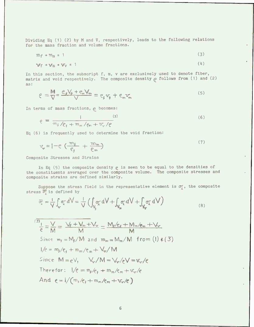
Dividing Eq (1) (2) by M and V, respectively, leads to the following relations for the mass fraction and volume fractions.
TT) f + Tflm =1 (3)
Vf +VB *VV S
1 (4)
In this section, the subscript f, m, v are exclusively used to denote fiber, matrix and void respectively. The composite density ^ follows from (1) and (2)
as:
M efVfieX > v (5)
In terms of mass fractions, ^ becomes:
I fl) (6) ^ ' ™f /Ci + ™m /fm + ^ /f
Eq (6) is frequently used to determine the void fraction:
Composite Stresses and Strains
In Eq (5) the composite density £ is seen to be equal to the densities of the constituents averaged over the composite volume. The composite stresses and composite strains are defined similarly.
Suppose the stress field in the representative element is o^, the composite stress <r[ is defined by
«MM M
Since ™, = M,/M and imro = Mn)/M from (1)4.(3)
l/e - "V/e< + %/^ + VM
i.nce M=eV, Vv/M = Vv/<V=vv/e
Therefor: ]/» = %/f , + mm/<m -+- vv/e
And (= l/(mf /(?, ■+■ mm/tm -f-vv/e )
(8)

We now introduce the volume average stress 0JL and 0^t in the fibers and matrix, respectively, ,
n v Jy « , * (9)
* = J_r <rdV mi Y.V.1
since no stress is transmitted in the voids (i.e. 0^=0 within Vv ), Eq (8) can be written as
5r = ^5;i-rv-rnö-mi (10)
Similarly to the composite stress, the composite strain is defined as the volume-average strain, and is obtained as:
Unlike the stress, the strain in voids does not vanish. The void strain is defined in terms of the boundary displacements of the voids. However, since the void fraction is usually negligible i.e., less than 1$,
*i=Vi*n+Vjwn (12)
with understanding that ( Vj. + Vm ) is unity.
Note that Eq (10) and (11) simply follow from the definitions of the composite stress and strain that the composite variables are the volume average. Thus these equations are valid regardless of the material behavior.
Rule of Mixture
Predictions of the response of a unidirectionally reinforced composite were based initially upon postulated states of stress and load transfer mechanism. The outgrowth of these analyses was the Rule-of-Mixture.
By assuming an isostrain criterion, i.e., both fiber and matrix are strained equally and uniformly, the longitudinal and transverse strength, stiffness, and the major and minor Poisson's ratio are found by the use of parallel and series spring models. The assumptions are:
o Elastic and plastic isotropy
o Perfect mechanics continuum at interface
o No chemical reaction between constituents
o An absence of residual stress
o An absence of rheological interaction at interfaces.
o Definability of in-situ properties of both fiber and matrix properties at the strains in question.

Experimental data have shown that only the longitudinal modulus and major Poisson's ratio can be reliably predicted by these simple approximations. Kelly and Davies (ref 2) reported these approximations as:
E„=E:,vf + Ew(l-V,) (13)
where E^ = Young's modulus of the composite parallel to the fibers
F = Young's modulus of the fiber
Em = Young's modulus of the matrix
♦0,2 = major Poisson's ratio of the composite
-\)j = Poisson's ratio of the fiber
<0m = Poisson's ratio of the matrix
\Tf = Vol % of fiber in the composite
According to the rule-of-mixtures prediction, the longitudinal strength of the composite would be:
K = e?vf+orm(|_v}) (15)
where (F', = stress in the fiber
0^ = stress in the matrix, at the fracture strain of the composite.
This prediction of longitudinal strength in Eq 15 is the one that has proven so useful in practice. The previous equations give properties such as the modulus which are rather insensitive to important factors such as the nature of the filament or matrix interface.
Strength
Unidirectional composites possess excellent strength and stiffness in the longitudinal direction because load is carried mostly by fibers. In the other loading conditions, the load sharing is about equal between fibers and matrix; therefore, composite strengths are comparable to those of the matrix used. Another parameter which plays a very important role in the strength of composites is the interface between fiber and matrix.
Failure of a material is initiated at the weakest point. A weak interface will certainly lead to a premature failure when a substantial load sharing is expected at the interface.
Load sharing by constituent phases depends on the type of loading. Therefore, we shall discuss strengths of unidirectional composites under five different loadings: longitudinal tension and compression, transverse tension
and compression, and shear.
Consider a unidirectional composite subjected to a unidirectional tension in the fiber direction. Since "e"^ * T"m% m "€fx , Figure 2 (ref 5 ) schematically presents the stresses in the constituent phases. This figure has been constructed based on the following observations.
1st: Fiber is linear elastic up to fracture.
2nd: Matrix is linear initially, then nonlinear as strain increases.
The strain at which nonlinearity starts to appear is greater than the fracture strain of the fiber.
Since not all fibers are expected to be of equal strength and equally stressed, some fibers will fail before others. When these fibers break, there are three modes of further damage growth depending on the properties of the matrix and interface.
If the matrix is brittle and the interface strong, the cracks created by the fiber breaks will propagate through the matrix across the neighboring fibers, leading to the composite failure.
If the interface is weak, then interfacial failure can be initiated at the fiber breaks and the fiber matrix debonding will grow along the broken fibers. A longitudinal damage growth is also possible in the form of matrix yielding between fibers.
If the matrix is ductile with low yield stress, as far as the composite strength is concerned, the latter two modes of damage growth have a similar effect.
Therefore, we shall simply divide the failure mode under a longitudinal tension into the transverse crack propagation mode and the longitudinal damage growth mode. The transverse crack propagation mode is in fact what is observed in brittle, homogeneous materials. In this failure mode, the strength of stronger fibers cannot be fully utilized, and hence the composite strength is not optimum.
In the other extreme case of complete longitudinal damage growth mode, broken fibers are simply separated from intact ones as far as load sharing is concerned, and the composite behaves like a dry bundle of fibers.
CONSOLIDATION PROCESSES
A wide variety of metallurgical processes have been employed for the fabrication of filament reinforced metal matrix composites. Major attention has been placed on diffusion bonding and more recently, spray bonding as the preferred methods.
Each process employed to consolidate a composite structure requires specific methods to deal with the highly anisotropic materials and relatively fragile reinforcing filaments, thus differing from conventional metallurgical techniques. Each process employed must meet to some reasonable degree the following objectives:
o Incorporate the filament without breakage.
o Consolidate the composite with minimal filament degradation.
o Establish and maintain filament alignment.
o Achieve a high density matrix.
o Offer variable filament volume loading.
o Establish filament-matrix interfacial bond sufficient to transmit applied load from matrix to filament.
o Allow for post fabrication heat treatment.
o Allow a degree of matrix selection and alloying.
o Give flexibility in filament spacing.
o Some methods must provide capability for cross and angle ply lay-ups.
o Minimize product variability.
o Be amenable to scaling up.
The consolidation processes used for metal matrix composites are: diffusion bonding, plasma spray bonding, electro forming, liquid metal infiltration, high energy rate forming and hot rolling bonding.
Diffusion Bonding
The most widely used method of consolidation of metal matrix composites is simultaneous application of heat and pressure, known as diffusion bonding. It is a static pressure process as differentiated from high energy methods which use dynamic pressure techniques. This method is used commonly to consolidate B/Al, Borsic/Al, Ti/SiC and Ti/Borsic composites.
The diffusion bonding process for a single uniaxial filament reinforced metal matrix is shown schematically in Figure 3 (ref6).
Using diffusion bonding as the most advanced consolidation process, marked improvements in the properties of B/Al composites have been achieved. Optimizing the fabrication parameters, utilizing the wide diameter 5.6 mil boron filament, and heat treating the composite material have produced excellent results. Maximum values for 48 V/0 5.6 mil B/6061 Al (uniaxial reinforced, heat treated) have been reported as 220,000 psi longitudinal tensile
10

strength, over 40,000 psi transverse tensile strength, and 625,000 psi compression strength.
Plasma Spray Bonding
Plasma spray bonding to prepare monolayer tapes for consolidation by diffusion bonding into thicker sections, has become an important consolidation process. The rate of powder feed affects the spray deposit in terms of deposit efficiency and quality of matrix filament bond achieved. Good results were achieved at feed rates of 3 lb/hr of metal powder, 240 to 400 mesh, at 4 to 5 inches torch to substrate.
Electroforming
Electrodeposition in the fabrication of metal matrix composites was one of the first methods studied because the composite could be formed at low temperature, thus minimizing the degradation of reactive filaments in metal matrices. A schematic of the electroforming process is shown in Figure 4 (ref 7).
Two practical limitations which seem to be inherent in the electroforming process are:
o The impurities which are incorporated into the composite from the bath during deposition.
o The inability to deposite alloys from solution.
A number of advantages can be cited for this process, including:
o A low room temperature fabrication process.
o A high density monofilaraent matrix can be obtained.
o Excellent filament matrix interface contact is possible.
o Filament spacing is accurately controlled.
o Volume loading of reinforcement is quite flexible.
o A variety of mandrell shapes can be accommodated.
Due to its inherent limitations, this method has marginal utility and serious problems for most metal matrix composites.
Liquid Metal Infiltration
Several model refractory metal systems have been consolidated in this manner such as tungsten reinforced copper, where little or no mutual solubility exists. The tungsten wires collimated in a ceramic tube were infiltrated by liquid copper. The technique is limited and had not received wide use because
11

of the few reinforcements which are stable in molten metals. This technique has been employed on AI2O3 whisker reinforced composites. The problem with the AI2O3 whisker in matrices such as aluminum and nickel has not been whisker degradation reactions, but rather the proper wetting of the whisker with the matrix. The wetting is controlled by various coating, matrix alloying, and control of the infiltration atmosphere. This process is shown in Figure 5 (ref 7).
High Energy Rate Forming
Very high pressure pulses of short duration have been utilized to fabricate composites in a method known as high energy rate forming. The method draws its advantage from the instantaneous application of very high pressures for very short time periods which prevents interaction of matrix and filament or whisker reinforcement while providing densitification of reasonably complex shapes. The typical conditions for this process are applied pressures of 400,000 psi and energy pulse duration of micro-to-milliseconds. A schematic process is shown in Figure 6 (ref 7).
Hot Rolling Bonding
The simultaneous application of heat and pressure in the diffusion bonding process has been modified to provide for a short reaction time during fabrication in a process known as hot rolling bonding. This method has been extensively employed by Metcalfe and his co-workers to counter the reacting problem with a reactive system such as BTi. The roll bonding method provides for a very short time of contact between the filaments and matrix at bonding temperature, but is practically limited to tapes as monolayers or a few layers thick.
A major problem in hot rolling bonding is the difficulty in obtaining high volume loading of the filaments. Another is cross- and angle-ply configurations which, for diffusion bonded sheets in alternate directions, are reasonably straight forward. For thin tapes this is a big problem in consolidation. The schematic process is shown in Figure 7 (ref 8),
MECHANICAL PROPERTIES OF COMPOSITE MATERIALS
Strength
The strength of unidirectional and multidirectional composites can be determined by quadratic interaction failure criteria in stress and strain space.
Failure Criteria
For the determination of strength of any material, it is the usual practice to estimate the stress at the time and location when failure occurs. In the case of conventional materials, we need only to determine the maximum tensile, compressive or shear stress and can make some observation about the failure and failure mechanism. This process is relatively straightforward because Isotropie materials have no preferential orientation and usually one strength constant will suffice. The isotropic material is essentially a one dimensional or one
12
constant material. The Young's modulus for stiffness will suffice because Poisson's ratio is taken to be about 0.3 and the uniaxial tensile strength will also suffice because the shear strength is taken to be about 50 to 60% of the tensile.
For the composite materials, however, the one constant approach for stiffness or for strength is no longer adequate. We saw earlier that four elastic constants were needed for the strength of unidirectional composites. We know that unidirectional composites have highly directionally dependent strengths. The longitudinal strength can be twenty times that of the transverse and shear strength. So we cannot say quickly that specific stress components are responsible for the failure.
The determination of strength using failure criteria is based on the assumption that the material is homogeneous (properties do not vary from point to point) and its strength can be experimentally measured with simple tests. Failure criteria provide the analytic relation for the strength under combined stresses. There is another approach for strength determination, using fracture mechanics. A material is assumed to contain flaws. The dominant flaw based on its size, shape, and location determines the strength when its growth cannot be stopped.
For composite materials, we need a failure criterion for the unidirectional plies. The strength of a laminated composite will be based on the strength of the individual plies within a laminate. We would expect successive ply failures as the applied load to a laminate increased. We will have the first ply failure (FPF) to be followed by other ply failures until the last ply failure which would be the ultimate failure of the laminate. The ply stress and ply strain calculations for symmetric and general (random) laminates are intended for strength determination.
There are two popular approaches for failure criteria of unidirectional composites. They are all based on the on-axis stress or strain as the basic variable.
Maximum Stress and Strain Criteria
9-sX, °;SY, <^£s de)
Failure occurs when one of the equalities is met. Using the linear relation we can express the equation above in the maximum strain criterion:
^sX/E,, €**Y/E,, *s-ss (17)
Failure occurs when one of the equalities is met. These two criteria are not the same. Only when Poisson's ratio of the unidirectional material is zero, does the criteria become identical; conceptually they are similar. Each component of stress or strain has its own criterion and is not affected by the
13

components. There is no interaction.
Quadratic Interaction Criterion
This can be expressed in strain components:
<*M+
GA-I (19)
Failure occurs when either equation is met.
Failure criteria serve important functions in the design and sizing of composite laminates. The criteria are not intended to explain the mechanisms of failure. Failure in composite materials involve many modes: viz., fiber failure, matrix failure, delamination, interfacial failures and buckling. Furthermore, the various modes interact and can occur concurrently and sequentially.
Quadratic Failure Criterion
Eq 18 can be expanded for the case of two-dimensional stress or 1- ; = 12 6
F„ «!*+ 2FM or <r2 +f^2 +FU <r,
2+2F„«;«i +2^«^
♦fa*^+ ->«*! <20)
since undirectional composite is in its orthotropic axis, as shown in Figure 8 (ref 5).
The strength should be unaffected by the direction or sign of the shear stress component. If the shear stress is reversed, the strength should remain the same.
Sign reversal for the normal stress components, say from tensile to compressive, is expected to have a significant effect on the strength of composite. Thus, all terras in Eq 20 that contain linear or first-degree shear strength must be deleted from the equation. There are three such terms:
fr«e;«;»f:»»oin»F>s (21)
Since the stress components are in general not zero, the only way to ensure that the terms above vanish is for
F„ = Fs, = Fs = 0 (22)
With the removal of the three terms, Eq 20 can be simplified:
F„^*+2^oir,+fi,rl» + FMr« + F^ + F,r,-l (23)
Of the six material constants or strength parameters, five can be measured by performing simple tests.
14

Longitudinil Tensile and Compressive Tests
Let X= longitudinal tensile strength
X= longitudinal compressive strength
These strengths are measured by uniaxial tests shown in Figure 9 (ref *♦). Substituting the measured strength into Eq 23.
If o; -X <*4)
FX,X2 + FXX= 1
if o-;« -X' (25)
F,^2 - Fxx'= 1
So we can get
Fxlt = l/XX', Fy = 1/X - 1/x' (26)
Transverse Tensile and Compressive Tests
Let Y = transverse tensile strength
Y ■ transverse compressive strength
Fyy= 1/YY', Fy = 1/Y - 1/Y' (27)
Longitudinal Shear Stress
Let S ■ longitudinal shear stress
F,$=l/S2 (28)
So we obtained five of six coefficients in failure criterion of Eq 23. The one remaining term is related to the interaction between the two normal stress components. The only way that these coefficients can be measured is both normal stress components to be non zero; this requires a combined stress biaxial test. This experimental task unfortunately is not easy to perform as the simple uniaxial or shear test.
Strength data for other unidirectional composites is in Table 4 (ref 5 ) and the strength parameters are listed in Table 5 (ref5 ) and Table 6 (ref5 ) for stress and strain spaced representations of the strength parameters, respectively.
15

Tensile Properties
Stress and Strain Behavior
The tensile properties of state of the art boron-reinforced aluminum and titanium are summarized in Table 7 (ref 2). Typical stress-strain diagrams for unidirectionally reinforced B/Al composites tested parallel (0°) and perpendicular (90°) to the direction of reinforcement are shown in Figure 10 (ref 9).
There are several interesting features of these stress-strain curves which deserve special mention. If the 0° curve is critically examined three distinct regions are noted, as schematically shown in Figure 11 (ref 10). With the initial application of load, both phases deform elastically with the rule-of-raixture relation giving a fairly accurate prediction of modulus. Eventually, the yield strength of the matrix is exceeded and the matrix begins to flow plastically. As a result, the matrix contribution to composite stiffness is substantially reduced. Composite stiffness at a given strain is then determined by the weighted average of the modulus of the reinforcement and instantaneous strain hardening rate of the matrix, dc/dc. In the case of B/Al, dC/d€ for aluminum is negligibly small compared with the 59 x 10" psi modulus of boron filament. The slope of the stress-strain curve in this region is referred to as the system secondary modulus and is generally 70 to 90% of the initial modulus. The stress-strain behavior in this second region is, of course, neither elastic nor linear.
The system experiences permanent deformation by reason of matrix flow and breakage of severely weakened filaments, and the srain hardening rate of matrix is not necessarily constant, although changes in matrix hardening rate have little influence on the composite stress-strain behavior in this region. This second stage continues until filament breakage is encountered, whereupon the slope of the stress-strain diagram is again observed to decrease (stage III), eventually resulting in composite fracture.
If the yield strain of the matrix exceeds the fracture strain of the brittle filament, stage II - type behavior will not be observed.
The transition from stage I and stage II depends on the yield strength (or strain) of the matrix and the magnitude of residual consolidation stresses. In the case of ductile metal wire reinforcement, Stage III is extended because both phases are capable of deforming plastically, causing failure to be postponed.
A rule-of-mixture type prediction of composite tensile strength will require knowledge of the stress-strain behavior of each component under the conditions it would experience in the composite. This includes such subtle points as matrix grain size, impurity distribution, consolidation induced defects, the interdiffusion of components, and the presence of reaction products. Filament strength and strain-to-failure must reflect the chemical and/or mechanical degradation resulting from consolidation and forming operations.
16

Since filament tensile strength is sensitive to gage length, it is very conservative to use filament strengths measured on 1 inch gage lengths in composites where the critical load transfer length is generally less than 0.1 inch. The influence of closely spaced, stiff and strong filaments on the flow stress of the matrix and the possibility of chemical change as a result of reaction with the filaments must be considered.
Residual consolidation stresses will influence the response of both phases to applied loads. Using the isostrain criterion, the contribution of each phase to the composite 0° tensile strength will depend on the strength developed in the two phases at the flow fracture strain of the brittle filament. Composite failure strains are generally between 0.3 and 0.6%. Anything which reduces the strain-to-failure of the filaments will be directly evidenced in reduced composite 0° tensile strength.
Residual Stress
Residual consolidation stresses arise because of the thermal expansion mismatch of two components. For instance, the thermal expansion coefficient of boron is 2.8 micro-in/in/°F while 6061 aluminum is 13.1 micro-in/in/°F and titanium 6 A1-4V is 4.7 micro-in/in/°F.
Since consolidation of filament and metal takes place at relatively high temperatures (1000°F for B/Al and 1500°F for B/Ti), these differences in expansion coefficient will result in the formation of longitudinal and radial residual compressive stresses on the filaments and corresponding tensile stresses in the matrix. Quantitative estimates of the magnitude of these residual stresses have been made, but these estimates are complicated by the relaxation of the matrix both during cooling from the consolidation temperature and at room temperature after consolidation.
In most cases one finds that matrix yielding takes place during cooling so that in the absence of relaxation the matrix can exhibit no elastic deformation when the composite is loaded in tension. Since elastic behavior is observed one must conclude that matrix relaxation has taken place. If the filament-matrix bond strength is inadequate, cooling will result in slippage along this boundary instead of causing matrix strain hardening, and the magnitude of the resultant residual stresses will be reduced. This condition, however, has never been observed in systems of practical interest.
Low composite failure strains have been observed for these cross-and angle-plied materials using normal consolidation process. A technique which has helped alleviate this matrix triaxial tensile stress state is a low temperature quench. Cooling the composites below room temperature cause further matrix flow to help accommodate the thermal expansion mismatch. Subsequent heating to room temperature causes a relaxation of the residual stresses and an increase in composite failure strain.
17

Transverse Tensile Properties
There is a striking difference between the 0° and 90° tensile properties of these unidirectionally reinforced materials (Table 7 and Figure 9). The tensile modulus, strength, and ductility are all lower for transverse tensile tests than longitudinal tensile tests. In fact, there is a 10:1 difference in strength and a 1.5:1 difference in modulus. The lower moduli and strength are, in part, due to the fact that the Lsostrain criterion no longer applies. That is, the matrix is free to flow nearly independently of the filaments. Under these conditions it becomes more difficult to predict composite stiffness and strength. If, however, the filaments are well bonded to the matrix and free of defects, the transverse strength should approach or exceed the strength of the bulk matrix alloy. The slight strength reduction can be related to structural imperfections in composites and the splitting of very weak boron filaments.
Quantitative examination of the fracture surfaces indicates that in all cases the relative area of split filaments on the fracture is less than the Vol % boron in the composite.
Failure is controlled by matrix properties. This contrasts with composites where the matrix has been heat treated and aged to a T-6 condition. The matrix is now substantially stronger than the majority of the boron filaments (i.e. 45,000 psi for T-6 6061 Al compared with 30,000 psi mode for boron filament splitting).
Here the transverse strength is found to be a fairly sensitive function of boron content as would be expected if filament splitting controls the composite failure. Generally, the relative area of split filaments on the fracture surface is found to be larger than the Vol % boron, which clearly indicates that the filaments offered the least resistance to crack propagation and probably control composite failure. The higher transverse strengths of the heat treated system at all reinforcement levels reflect the high strength and stress concentration accommodation ability of the matrix.
Improvement of the transverse properties of unidirectionally reinforced B/Al can be accompanied by development of improved filaments, by third phase additions, or by heat treatment of the matrix. An alternate solution is to use cross-or angle-plied B/Al where substantial off-axis loads are anticipated. The use of cross-or angle-plies:
o imposes a reduced upper limit on the volume fraction of boron filament since interpenetration of adjacent boron layers becomes impossible,
o increases the probability of introducing filament defects during consolidation, and
o introduces complex shear forces between adjacent boron layers.
18

None of these features in themselves would eliminate cross-or angle- plied composites from active consideration but they do introduce complexities which, in most cases, could be avoided if the transverse strength of unidirectional composites were increased to MO - 50,000 psi. The first of the solutions, improved filaments, is being pursued by the development of the larger diameter (8 mil) boron filament, by the use of different boron filament substrates (carbon), and by the development of additional varieties of filament (SiC, AI2O3, and graphite). The filament development is usually, however, a long and costly process. The second solution, third phase additions, shows great promise. Composites have been fabricated and tested with minor (5-15 Vol$) 90O stainless steel wire additions and with layers of titanium foil which demonstrate substantial improvements in transverse properties without materially affecting longitudinal properties. Matrix heat treatment, in addition to modifying the matrix strength and its susceptability to stress concentrations, can also be used to change the residual stress state in the composite. Because of the higher thermal expansion coefficient of aluminum and titanium relative to boron, rapid cooling will result in residual radial compressive stresses on the boron filament which may increase composite transverse strength and ductility in those systems currently limited by filament splitting.
Compression
The ultimate strength of composites tested in compression has been found to equal or exceed their ultimate tensile strength. The modulus of elasticity is nearly identical in tension and compression. Typical stress - strain diagrams for 0° and 90° specimens tested in compression are shown in Figure 12 (ref 11).
The compression of 0.20 x 0.25 x 0.75 inch specimens of unidirectionally- reinforced 50 Vol % Borsic /Al parallel to the filaments (Figure 12) resulted in a modulus of 3M x 10^ psi and a compressive strength of 297,000 psi with failure occurring as a result of the "brooming" of one end of the specimen.
In comparison, a similar sized specimen tested (Figure 13) (ref 12)at 90° to the filaments resulted in a modulus of 20 x 10" psi and an ultimate compressive strength of 37,000 psi. The 0° compressive strength is very much more sensitive to boron content than the 90° strength, the transverse compressive strength being determined primarily by the shear strength of the matrix.
Impact
The impact energy for 50 Vol % Borsic - aluminum composites, as determined from full size Charpy "VM notch specimens is shown in Figure 1M (ref 13), The LT notch-filament configuration not only yields the highest impact energy but also demonstrates an increase in energy absorption capacity with increasing boron content. In comparison, the TT and TL notch-filament configurations have much lower energy absorption capacity and appear to be insensitive to boron content. In the case of LT notch filament configuration, the crack front is propagating normal to the filaments with composite failure requiring the fracture of all filaments in the cross section. With this configuration, cracks can be deflected parallel to the filaments along the filament-matrix interface, thereby increasing the composites energy absorption capacity. The stresses normal to
19
the filament are considerably smaller than is the case for the other two configurations. In contrast, cracks propagating in the TT and TL specimens are not required to fracture all the boron filaments in the cross section. Instead, the high transverse stresses acting on the filament near the crack tip cause the filament to split longitudinally. The stress required to cause longitudinal filament splitting ( 30,000 psi) is considerably less than the stress required for the fracture of boron filaments normal to their axis ( 450,000 psi).
Although the strengths cited above cannot be directly applied to impact energy predictions, they do indicate that the filament will be able to make a larger contribution to the composites energy absorption capacity in the LT configuration as compared with the TT and TL configuration. In addition, longitudinal filament splitting can provide an easy path for crack propagation in the case of the TT and TL configuration. The slight improvement of the TT configuration relative to the TL configuration may result from a larger matrix contribution to impact energy in the TT case. More extensive plastic deformation is possible around the filaments which run parallel to the crack front in the TT specimen. In comparison, relatively little plastic deformation can take place in the TL specimen without transferring load into the filaments, since the slip bonds will necessarily intersect the filament.
Elevated Temperature Tensile Strength
The variation of ultimate tensile strength of unidirectional B/Al composites with test temperatures is shown in Figure 15 (ref 12). For comparative purpose, the variation of tensile strength with temperature for 6061 aluminum is also shown. The most important observation is that the composites retain their strength exceptionally well up to about 600°F. At 600°F the composite tensile strengths are still 10 to 30 times higher than the tensile strength of the aluminum alloy matrix. The variation of ultimate tensile strength of cross and angle ply B/Al composites is shown in Figure 16 (ref 12), Notice that the +5° angle-ply and 0° to 90° cross-ply composites have the same temperature dependence as the unidirectional composites shown in Figure 16, while the +30° angle-ply composites reflect the decreasing matrix strength above 300°F.
The temperature dependence of boron filament strength is not presented in Figure 15, but strength reductions of 20 to 40% have been reported from room temperature tensile strength of approximately 500,000 psi. The observed composite strengths at 750°F are less than rule-of-mixtures predictions, even if a 40% filament strength reduction is assumed.
The direct application of filament tensile data to composite strength predictions is often times quite misleading, particularly at elevated temperatures where the chemical reactivity of the filament with the atmosphere or metal matrix introduces an additional complexity.
The variation of transverse tensile strength with test temperature for 25, 37 and 50% B/6061 Al composite is shown in Figure 17 (ref 12). The temperature dependence of the transverse strength of these composites is independent of the reinforcement content.
20

IMPROVED MECHANICAL PROPERTIES
Introduction
Wider diameter filaments not only have increased transverse strength, but also improved reliability of their longitudinal strength. For example, the amount of 5.6 mil boron filaments below 400,000 psi longitudinal tensile strength is only 10% compared to 20% of the 4.0 mil boron filament. This is perhaps more significant than the increase in average tensile strength by about 25,000 psi since it is the weak filaments that will fail first, and perhaps initiate premature composite failure. Filament splitting has also been substantially reduced, eliminating a major problem in premature failure.
Improved Filament
To avoid adverse reactions between the boron filament and metals during high temperature fabrication of metal matrix composites, the surface of the boron filament is coated with a diffusion barrier of boron carbide (B4C). Excellent filament properties are maintained in both aluminum and titanium matrix composites. The strength of the B4C coated boron filament is superior to the boron and the SiC coated boron filament. A typical set of filament test data shows that the strength of boron is increased by the addition of a layer of B4C (Figure 18) (ref 6). The average strength for boron is over 500 ksi, increased to over 600 ksi for B4C coated boron and reduced to below 500 ksi for silicon carbide boron.
A low cost silicon carbide filament is developing for the reinforcement of metal matrix composites. The silicon carbide filament is potentially very low cost and is compatible with high temperature processing in aluminum and titanium. It's tensile strength is 500 ksi, modulus is 62 Msi and density is 0.11 lb/in3.
Improved Composites
The properties of B/Al composites as reported by various commerical sources have been compiled in Table 8 (ref 2). There are two trends that should be noted. One is that the wide diameter filaments give consistently higher composite strengths in both the longitudinal and transverse orientations. The other is that heat treatment to the T-6 condition for an aluminum alloy with wide diameter filament improved the properties significantly. The maximum values of 230,000 psi for longitudinal tensile strength of B/6061-T6 Al and 45,000 psi for transverse tensile strength of B/2024-T6 Al are indeed encouraging.
The properties of several B/Ti composites are given in Table 9 (ref 2). Here, the excellent longitudinal and transverse strengths of the composite with large diameter boron are easily seen. The value of 185,000 psi and 64,000 psi respectively, for a B/Ti-6A1-4V composite are quite promising. The transverse tensile strength of the titanium composite containing wide diameter boron is markedly superior, just as was the result for aluminum matrix composites.
21

A critical property evaluation of the best available aluminum and titanium alloy matrix composites with boron filament reinforcement has recently been completed by Kreider, Dardi and Prewo (ref 14).. This investigation has produced an important body of information on composite behavior including bonding conditions, environmental effects, transverse properties, off-axis properties, failure mechanisms in fatigue, notch bending fracture, and notched tensile fracture behavior. A few of their major findings will be considered here. Longitudinal tensile strengths for 5.6 mil B with various Al alloys are shown in Table 10 (ref 14). A very high volume loading was achieved, as high as 70 Vol% B in 2024 Al. Thus, strengths to nearly 280,000 psi were obtained with an elastic modulus value of 40x10° psi.
Longitudinal strengths for Borsic/Al are listed in Table 11 (ref 14). Here, volume loadings of about 60% Borsic have been obtained with strengths exceeding 200,000 psi and moduli approaching 40xl06 psi.
The transverse tensile strengths for 5.6 mil B in various Al alloys are shown in Table 12 (ref 14). The transverse strength of B/2024-T6 Al in this case is almost 50,000 psi for a 45 Vol % loading. The heat treatment to the T6 condition again much improves the values. This importance of T6 treatment is again seen in Table 13 (ref 14) where an extensive series of tests is reported for 5.7 mil Borsic/Al composites.
The change in longitudinal tensile strength with temperature for a 5.6 mil B/6061 Al composite is given in Table 14 (ref 14). The decrease in strength with temperature is similar to that found for 4.0 mil boron composites. The transverse strength curve with temperature is much higher for the wide diameter filament reinforcement at low temperature in a heat treated matrix than for the smaller diameter filament or an untreated matrix.
22

APPLICATIONS
Introduction
The introduction of advanced composites began in 1965 with boron fiber and since that time rapid advances have been made toward application of these composites to military aircraft. The significant weight advantages and the success of these developments have led to production commitments on fighter empennage structures.
The potential for significant weight reductions in aerospace structures through the use of advanced composites was first realized on a broad scale by the military In the Air Force Project "Forecast" conducted in 1963. This observation was based on the then recent developeraent of the high modulus, high strength, low density boron fiber and the superior mechanical properties that could be developed when these fibers were converted into composite laminates. Since that time, other filament have been developed that offer equal or increased potential for reduced structural weight, increased stiffness and lower cost.
The first pioneering work in fiber glass structure was carried out at the Wright-Patterson Air Force Base, Ohio, in the early 1940's. By 1943 a BT-15 fuselage of sandwich construction with fiber glass faces and balsa wood core had been static tested. Flight tests of this structure were performed March 1944. On a strength to weight basis, the fiber glass fuselage was 50% stronger than an aluminum structure. In May 1945 the first fiber glass reinforced AT-6C wing was fabricated.
Examples of Applications
The current state-of-the-art of advanced composite structures has entered the stage where limited application is beginning to be seen on some current production and prototype military aircraft systems, such as wing and fuselage section components, empennage, helicopter rotors, etc. Other examples are gear wheels for lubricating and coolant pumps, gear case housing for Allison T-56-A- 18, golf club shafts, rackets, and fishing rods.
In the case of gear wheels, carbon reinforced plastics may be promising for such light weight, self lubricating gears. The potential advantages of fiber reinforced plastic gear wheels are as follows:
o self lubricating, simplifying design,
o will not rust and are chemically resistant,
o reduced maintenance requirement,
o low weight and, therefore, inertia,
o high strengths and stiffness,
23

o low coefficient of thermal expansion,
o low coefficient of friction and low heat generated, and
o low wear rate.
For the gear case housing, the Allison T-56-A-18 turboprop reduction gear assembly gear was fabricated by Goodyear Aerospace Corporation under a US Navy contract. Normally, the conventional material of construction is cast magnesium. The composite design was fabricated from 1 inch chopped boron- fiberglass reinforced epoxy, and provided the following advantages:
o molded composite gear case as strong as the magnesium counterpart,
o 13% lighter and approximately twice as stiff, and
o eliminating internal ribs and adding external stiffness resulted in a reduction of parastic power loss.
For such applications as above, elimination of costly machining and material wastage, precise dimensional control, and tailoring of strength and stiffness are further advantages of a molded advanced composite glass system.
Cost
In the case of B/Al, Alexander showed the cost history in Figure 19 (ref 15). For comparison, the cost analysis by Toth is given in Figure 20 (ref 16).
For boron the picture is further improved with the acceptance of a larger diameter filament. The L971 average price for 4 mil boron filament was about $210 per lb. With 5.6 mil boron a cost reduction of almost 50% is obtained. Further reductions with increasing volume are expected.
Given their high property levels, the advanced composite materials with wide diameter boron can now provide real competition to some aerospace alloys. Assuming a reasonable market exists, it is possible to project costs of $50 per lb or less. These projections involve considerable guess work, but at least the general trend for B and B/Al has been steadily downward in price.
Further Applications
Present and future engineering design requirements demand a maximum of materials strength and stiffness at a minimum weight and potential for future use at temperatures above 1600° to 1800°F, as evidenced by the competition from the more familar directions of metallurgical development of polymer matrix composites. In comparison to other composite matrices, the most obvious potential advantage of the metal matrix is its resistance to severe environments, high specific stiffness and strength, low thermal expansion, retention of strength at high temperatures, and high thermal and electrical conductivities.
24

In a composite structure, it is possible to emphasize environmental stability of the matrix at elevated temperatures, since the required mechanical strength and stiffness can be obtained from the reinforcement.
Currently, metal matrix composites are recognized for their tremendous design advantages to space system designers and users. However, as the property to cost ratio of these materials and the awareness and knowledge of their advantages continue to increase, metal matrix composites will be used in many other high performance land-based and aerospace applications.
25


REFERENCES
1. A. G. Dietz, "Composite Materials," 1965 Edgar Marburg Lecture, American Society for Testing and Materials, Philadelphia, PA, 1965.
2. C. T. Lynch and J. P. Kershaw, Metal Matrix Composites, Chemical Rubber Company Press, 1972.
3. Composite Materials Dept., Hamilton Standard, Division of United Aircraft Corp., Windsor Locks, CT.
4. A. G. Metcalfe, "Interfaces in Metal Matrix Composites," Composite Mater- ials, Vol I, Academic Press, 1974.
5. S. W. Tsai and H. T. Hahn, Introduction to Composite Materials, Technomic Publishing Company, 1980.
6. AVCO brochure, "Boron Composite Materials."
7. J. A. Snide, C. T. Lynch, L. D. Whipple, "Current Developments in Fiber- Reinforced Composites," Technical Report AFML-TR-67-359, Feb 1968.
8. G. K. Schmitz and A. G. Metcalfe, "Development of Continuous Filament-Rein- forced Metal Tape," Technical Report AFML-TR-68-41, Feb 1968.
9. J. H. Young, "Advanced Composite Material Structural Hardware Development and Testing Program," AFML Report TM69-249, G. E. April 1969.
10. A. Kelly and G. J. Davies, Metallurgical Review, Vol 10, No. 1, 1965.
11. K. G. Kreider, L. Dardi and K. M. Prewo, Progress Report, Air Force Contract F33615-69-C-1539, Jan 1, 1970, Feb 1970.
12. W. H. Schaefer and J. L. Christian, "Evaluation of the Structural Behavior of Filament-Reinforced Metal Matrix Composites," Technical Report AFML-TR-69-36, Vol II, Jan 1969.
13. K. G. Kreider, L. Dardi and K. M. Prewo, "Metal Matrix Composite Technology," Technical Management Report for Contract F33615-69-C-1539, AFML, Wright-Pat- terson AFB, Ohio, Dec 1969.
14. K. G. Kreider, L. Dardi and K. M. Prewo, "Metal Matrix Composite Technology," Technical Report AFML-TR-71-204, Dec 1971.
15. J. A. Alexander, "Review of Metal Composites Programs," 17th Refractory Work- ing Group Meeting, Williamsburg, VA, June 1970.
16. I. J. Toth, W. D. Brentnall and G. D. Menke, "Aluminum Matrix Composites," AIME Fall Meeting, Detroit, MI, Oct 1971.
27


Tlble 1. FHameat pcoewrtia»
Material Tcmile Strenith
tktl)
Elastic Modulut
(X 10* pti)
Density Density (Ib/m*)
Strength/Density Ratio (X 10* in)
Beryllium Molybdenum Steel Tunptten
ISO 320 600 575
45 48 29 59
184 10.2 7.9
I9J
0.066 0.369 0286 0.697
2.73 0.88 210 0.83
E-Gla«t tOUM Silica
500 600 500
10.5 12.5 103
25 2.5 2.2
0.092 0092 0079
5.43 §53 543
Boron (on Tungsten) Craphne* Silicon Carbide (on Tungsten) Alumina
450 285 350 350
58 50 55 70
2.6 1.66 3.« 3.98
0.096 0.060 0123 0.144
4 68 4.75 284 2.43
Alumina Whiskers Sibton Carbide Whivkerc
2000 1500
70 70
3.98 3.2
0144 0.115
139 13.0
There are many type* varying in strength (150-375 ksi). modulus (25-75 X 10* psi), and density (1.5-2.0 g/cm').
Table 2. Boron*type filament properties
Property Unit 5.7 mil 4.2 mil 5.6 mil 4.0 mil
Du meter 10 »to. 5 7 g 01 4.0 t 0.2 5.6 t 0.1 3.9 t 0.2 Ultimate tensile strength 10» pi! 450 - 475 425 - 450 450 - 500 450-500 Minimum tensile strength 10» psi 300 300 350 335 Modulus of elasticity 10* psi 59-60 57-60 59-60 57-60 Density Bb/in.» 0.092 0096 0.090 0.095 Length per pound .ft 34.500 57,000 38.000 70.000
Table 3. Typical fiber properties
FaW Diameter Density Modulus Strength as» §/£■• GTi GPa
Graphite (T300.AS) 7 I.7S
Boron C4*I) 100 24
CUa (E) 16 24
(49) 12 144
330 2J0
410 345
72 145
120 342
Extracted from C. T. Lynch and J. P. Kershav, Metal Matrix Composites, Chemical Rubber Company (CRC), Boca Raton, FL cl972. Permission granted by CRC.
b Extracted from S. W. Tsai and H. T. Hahn, Introduction to Composite Materials, Technomic
Publishing Company, Lancaster, PA, cl980. Permission granted by Technomic Publishing Company.
29

Table 4. Tv^cal tfranftftt of imMiractionaf eompoartM in Mr»
Type Material "I X
ton,
r Trm»
r r Star
5
T300/5208 Crtphite /Epoxy 0.70 1500 1500 40 246 u
■(4)/5S05 Boron /Epoxy 030 1260 2500 61 202 67
AS/3501 Graphite /Epoxy 0-66 1447 1447 51.7 206 93
Scotchpty 1002
Glass /Epoxy 045 1062 «10 31 111 72
I>vUr49 /Epoxy
Anmid /Epoxy 0J60 1400 235 12 53 34
Aluminum 400 400 400 400 230
Tm
T300/5208
*4)/550S
AS/3 S01
■ Scotchpty 1002
KrvUr49 /Epoxy
T&b If 5TStr*nfih pvimtm in ttnm %*a» for «nidiraettonaf uumpuwrm
Type ftitceml <GHr* (CPar* (CM* <cp.r» (CPa)"1 (CPar1
T3O0/5208 - Crtphite /Epoxy A44 101« -33« 2163 0 20.93
■X4)/5505 Boron /Epoxy 317 •1.15 - 233 222.7 393 11.44
AS/3501 Crtphite /Epoxy 476 93 48 -333 1154 0 14.50
Scotchpty 1002
Clan /Epoxy 1.543 2733 -1037 192.9 - J897 23.78
KrvUr49 /Epoxy
Anmid /Epoxy 3J039 1572 -3436 •65.0 -3341 «4.46
Aluminum «35 635 - 3.125 13.90 0 0
Tlblt 6?S*vnr* parameter» In rtnin IPMI for wnidtr*cbortaf composite* tdlmetulonteat)
Material "*y CM, Cm C.
Crtphite /Epoxy
Boron /Epoxy
Graphite /Epoxy
Ctm /Epoxy
Aramid /Epoxy
Aluminum
12004
10374
7363
1913
13453
23387
10680
27646
7440
18881
47656
28387
-3069
-2988
-1743
1712
i
2068
1976
11117
«961
5821
3306
457«
13313
60 M
129«
3932
2436
-I49J
0
2163
2143
130.76
1980S
350.8
0
aExtracted from S. W. Tsai and H. T. Hahn, Introduction to Composite Materials, Technomic Publishing Company, Lancaster» PA, cl980. Permission granted by Technomic Publishing Company.
30

Table T. Tensüe aroperties of boron/aJuminum and boron/ titanium compotiles
50 v/o boron-Aluminum 50 v/o Boron-Tmnium
Weight Wright Base(psi) NormahzedOn.) Bsse(psi) NormaluedOn )
Ultimate Tensile Strength
Tensile Modulus
o- 165.000 1.78X10* 155.000 1 22 X 10*
90* 15.000 0 16X10* 30.000 0.24 X 10»
o- 334X10* 356 X 10* 38 OX 10* 300 X 10*
to* 21.0 X 10* 224 X 10» 28.0X10* 220X10*
Table 8. Properties of 50 v/o bosoa/elumlnirm
Matrix 4 heat Lonfitudinal Transverse (ku) Source Filament treatment condition tensile strength (ksi) tentik strength
A Borsic/4.2 mil 6O61-F.2024-F 165 13 A Boroc/4.2 mil 6O61-T6.2024-T6 180 20 ■ Boron/4.0 mil 4061-F 180 13.5 B Boron/4.0 mil 6061-T6 205 20 c Boron/4.0 mil 606 IF P5 10
c Boron/4.0 mfl 4061-T6 170 15 A Boruc/5 7 nil 6061-F 190 19 A Borsic/5.7 mfl 2024-F 190 27 A Borsic/5.7 mil 6061-T6 200 36 A Bonic/5.7 mil 2024-T6 200 45
B Boron/8.0 ml 6061-F 210 18 B Boron/8.0 mil 6061-T6 230 37 c Boron/5.6 mil 6061-F 180 18 c Boron/5.6 mil 6061 T6 175 25
Table 9. Properties of 50 v/o Borsic/titanium
Source Filament diameter matrix Longitudinal Transverse (ksi)
tensile strength (kxi) tensile strength
A 4.2 mil Benin 170 A 4.2 mil 6A1-4V 155 B 4.2 mfl 4AI-4V 140 C 5.7 mfl 4A1-4V 185
30 35 42 64
aExtracted from C. T. Lynch and J. P. Kershaw, Metal Matrix Composites, Chemical Rubber Company (CRC), Boca Raton, FL c!972. Permission granted by CRC.
31

Tab le 10. Axial teiuik strength of 5.6 mil B/Al
Matrix
2024F
2024-T6
2024F
6061F
6061-T6
v/o Boron Ultimate tensile Elastic Strain to
(%) strength (10' psi) modulus (10* psi) fracture (%)
45 185.7 30.4 0.765 45 197.5 27.5 0.835 44 177.0 30.0 0.725 47 212.0 32.0 0.825 47 212.0 32.6 0.820 49 194.0 32.0 0.740
46 202.5 32.8 0.75 46 213.6 31.6 0.81 47 217.0 32.3 0.830 48 213.0 31.3 0.845 64 279.0 40.0 0.755
70 279.5 - - 66 253.0 - " 67 250.2 —
48 196.3 31.8 0.710 48 171.0 28.2 0.590 50 204.0 33.8 0.72 50 208.0 32.0 0.76
52 216.5 33.8 0.78 51 197.0 33.4 0.69 50 203.0 — *"■
32

Table II* Axial ieiuale fftrength of 5.7 mil Borsk/Al composites
Matrix
6061-F
6061-T6
6061-F
6061-F
6061-F
6061-F
6061-F
2024-F
2024-T6
5052/56
1100/1145
v/o BORS1C (%)
Ultimate tensile strength (10» rm)
Elastic modulus (10* psi)
Strain to fracture
(%)
30 115.0 113.3
17.6 18.9
0.71 0.71
30 156.2 152.4
54 203.4 181.5 199.0
36.6 36.0 36.1
0.675 0.630 0.655
56 214.0 212.0
57 228.0 222.0
58 227.0 219.0 216.0 222.0
61 199.0 207.6
39.4 0.57
58 211.5 221.0
61 235.0 210.0
59 177.6 182.0
37.7 0.54
57 158.2 175.5
33
Table I 2 . Transvene tensile properties of 5.6 mil B/AI
Matrix
2024F
2024-T6
2024-T6
2024F
6061F
6061-T6
v/o Boron
UTS (10s psi)
Elastic modulus (104 psi)
Strain to failure (%)
45 45 45
27.0 27.2 26.2
45 45 45
48.0 48.7 38.2
55 41.9 45.0
21.0 22.5
0.23 0.24
66 26.0 27.3
50 50 50
18.9 19.0 18.3
50 50 50
34.8 37.4 41.7
34

Table 13. Transverse tensile properties of 5.7 mil Borsic/Ai
Matrix Boron v/o UTS (10* psi) Elastic modulus Strain to failure (%) (10*"psi)
606 IF 30
606I-T6 30
606 IF 52
6061-T6 52
606 IF 60
6061-T6 ' 60
606 IF 70
6061-T6 70
2024-F 56
2024-T6 56
5052/56 57
1100 54
16.0 140
15.0
»
0.45
35.1 34.6
15.5 0.31
19.3 20.5 19.3
31.2 36.6 39.8
18.9 19.0 21.0
0.19 0.23 0.24
19.9 19.7
24.0 . 0.26
44.0 37J
0.23
16.8 21.2 18.8 32.3 0.29
35.4 27.6
29.2 0.14
22.4 20.8
22.8 0.171
46.0 37.1
24.7 0.202
30.4 32.6
25.8 0.308 050
13.6 13.8 11.7
21.8 23.2
0.68 0.52 0.60
35
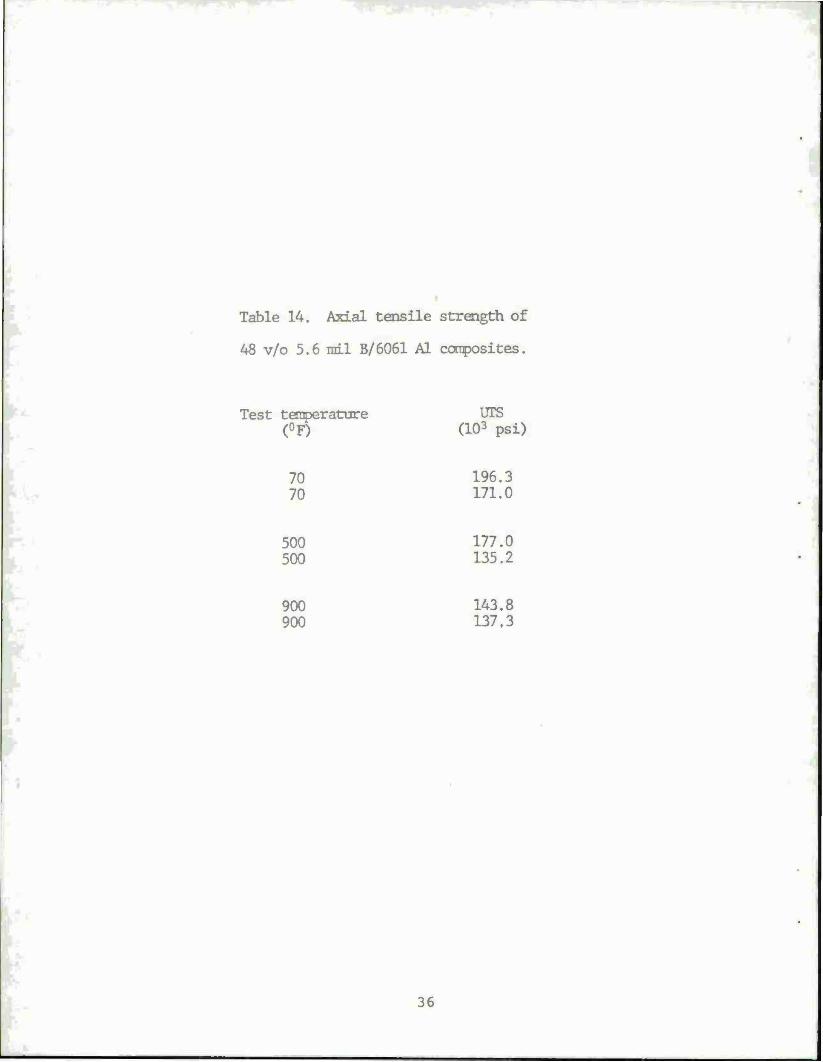
Table 14. Axial tensile strength of
48 v/o 5.6 rail B/6061 Al composites.
Test temperature UTS (°F) (103 psi)
70 196.3 70 171.0
500 177.0 500 135.2
900 143.8 900 137,3
36

Ml F /MM M M
I i I M(A.B)
-i MCA,B) M
MO,
(C) <0> <•)
Fio. I7 ßchematic of principal bond typ«: matrix M may conUin element« A end B end Element mey be tingle element (fuch ee frephite) identified ee F or compound (such ee AJ.O,) denoted ee FO.. (e) Mechanical bond, (b) diaeolution end wettinf bond, M. Cb-W, (e) reaction bond e.g., Ti-C, (d) exchange reaction (ej., Ti(Al>-B), (e) peeudo-Claei I oxide bond where AFM0» < AFeo, («••-. Al-B).
STMdIM
Ttjurt 2V Typical itmntnui raUtmm Of fibe». mjthx and conpoatt. The com- fodtc failure «train it dot* to the Aber failure niton The mttru k ftoafcaear tbovt the fiber failure atraia.
APPLY ALUMINUM FOIL
CUT TO SHAPE
TO VACUUM
LLL
LAY UP DESIRED
PLIES VACUUM ENCAPSULATE
HEAT TO FABRICATION
TEMPERATURE
TT¥ APPLY PRESSURE AND HOLD FOR
CONSOLIDATION CYCLE
COOL REMOVE. AND CLEAN PART
Figure 3. Composite materials fabrication pror—
aExtracted from A. G. Metcalfe, "Interfaces In Metal Matrix Composites," Composite Materials, Vol I, Academic Press, New York, New York, cl97A. Permission granted by Academic Press.
Extracted from S. W. Tsai and H. T. Hahn, Introduction to Composite Materials, Technomic Publishing Company, Lancaster, PA, cl980. Permission granted by Technomic Publishing Company.
37

1
i I
!
1
\\*^\
38

Figure 5. Schematic diagram of the apparatus for vacuum catting.
30

rittet HMartal
"■•»to,
Q—r%l\ Dimf t— • 1/1 - I 1/4 ■. «MM t- «». to*
Figure 6. Composite billet for hi|h enerfy-ratc forming composite plates.
40

MS •F„-F,-0
EfttTAMCt NtATtD
foe mArma
Figure 7. Hot-roll bonding. Figure 8. On-ax is positive and negative shears. They should have no effect on the strength of unidirectional composites. Coupling between shear and normal com- ponents cannot exist in this orthotropic orientation.
•►«i
Figure 9. Uniaxial longitudinal tensile and compressrve testa.
Extracted from S. W. Tsai and H. T. Hahn, Introduction to Composite Materials, Technomic Publishing Company, Lancaster, PA, cl980. Permission granted by Technomic Publishing Company.
Extracted from A. G. Metcalfe, "Interfaces in Metal Matrix Composites," Composite Materials, Voll, Academic Press, New York, New York, cl974. Permission granted by Academic Press.
Al

0.001 Q0O2 0009 0004 0006 000«
•TRAIN- m/m
Figure 10. Typical stress-strain curves for 50 vol % unidirectional boron/aluminum composites tested parallel (0*)and perpendicular (90°) to the filament.
/
/
4*. / S /(^amc FIM* 1 • ' X Nft.A$TlC MATRIX I
$ /jr/ mot* ruacTunq •» •> teJ
A / / 1«-A*TIC MATRIX
J4/ ac
fj/ A/
*A / JE LA trie riaca / jtLAtTlC MATRIX
STRAIN
Figure II. Schematic stress-strain curve for fila- mentary reinforced metals showing three reg ions.
42

Mil MU OJ)20 0JÖ4 0.021
fiqur t 1 2. Typical comprcuhrc strcsa-atrain curves for 50 vol % unidirectional boron/ •hi mm um compoatei tested parallel (0s) and perpendicular (90*) to the filament.
A3

s * ito
100
I 140
! 110
100
jQWOW- 001 ALumwuM
t- • o*-o.ouo* • o*-ooto° * •0»-0 010'
VOLUME fEMCtNT §OAGll
Figure 1 J. Vimtion of longitudinal and transverse com pr curve strength with boron content for unidirection- al boron/aluminum composite*.
2
MO
VOLUMf f ttClHT FILAMIMT
Fiqart l*. Variation or impact energy with filament content for various notch-fUament configurations for 46 vol % •oruc-6061 aluminum unidirectional composites.
4A

Q Ml M»0« -«L ( »I * /«/■$ §aiH MM'U mtfsW
»•*/. MOi-WW. //ri
140
ItO
100
•» to
I 5 to
200 500 4O0 900 TEST TE*««ATW»C *P
•00 700
Figure 15. Variation of longitudinal (0*) tensile ftrength with teit temperature for unidirectional boron (Boriic}-aluminum composite».
O A D
IS \ tONON - AL t 5* ANCLE-PLY («Er/5>
45% tO*ON-AL t SO* ANtLE-PLYltf* /4rf 41% BORON-AL 0- tO* C«OSi-PLY(NC*/40
_L. -U
100 200 SOO 4O0 too
TEIT TEMPERATURE •■
700
Rqur t 16. Variation of longitudinal (0*) tensile strength with test temperature for various cross- and angle-plied boron-aluminum composites.

z o I I I I I I 11 I I I I
J_l sisai do ouvd
» ■ I » i i » I i ■ ■ t I MM
§
s * S o m o CM *- ^
8
46

4000
3OÖ0
^1
ft
s i 2000
AJM
• Sourc* A 0 Sourc« I A ProJ«ct«d Tram httlM Prle« Lliti 0 Sourc« C * M'HiMr t/Al Sh.rc
«K>r*v - MÄ %J
47 » «I * ' » * * ill ■ m
LS <s rp n « rj m rs TL TT m WVfJP
Figure 19» Metal matrix composite cost history and projections.
1
"9W9* "(^ {•) eirruiioa i (■) Mw IMttffM (c) toariBuout CMTII
'»»
Figurc 20. Curcent and projected costs for fiber* and composites.


DISTRIBUTION LIST
Commander Armament Research and Development Center US Army Armament, Munitions and Chemical Command ATTN: DRSMC-GCL(D)
DRSMC-TSS(D) (5) DRSMC-TD(D) DRSMC-TDS(D) DRSMC-SCA(D) DRSMC-SCA-E(D) DRSMC-SCA-W(D) (20) DRSMC-SCS(D) DRSMC-LC(D) (2) DRSMC-LCA(D) DRSMC-LCW(D) DRSMC-SCM(D) DRSMC-SCM-P(D) DRSMC-SCM-O(D) DRSMC-SCM-O(D) DRSMC-RA(D) DRSMC-TPC(D)
Dover, NJ 07801-5001
Administrator Defense Technical Information Center ATTN: Accessions Division (12) Cameron Station Alexandria, VA 22314
Director US Army Materiel Systems Analysis Activity ATTN: DRXSY-MP Aberdeen Proving Ground, MD 21005
Commander Chemical Research and Development Center US Army Armament, Munitions and Chemical Command ATTN: DRSMC-CLJ-L(A)
DRSMC-CLB-PA(A) Aberdeen Proving Ground Edgewood Area, MD 21010
Director Ballistics Research Laboratory ATTN: DRXBR-OD-ST Aberdeen Proving Ground, MD 21005
49
Chief Benet Weapons Laboratory, LCWSL Armament Research and Development Center US Army Armament, Munitions and Chemical Command ATTN: DRSMC-LCB-TL
Watervliet, NY 12189
Commander US Army Armament, Munitions and Chemical command ATTN: DRSMC-LEP-L(R) Rock Island, IL 61299
Director US Army TRADOC Systems Analysis Activity ATTN: ATAA-SL White Sands Missile Range, N.M. 88002
50

