us army corps of engineers - defense technical … · file copy us army corps of engineers the...
TRANSCRIPT
FILE COPy
US Army Corpsof Engineers
The Hydrologic('J Engineering Center
I
G ENERALIZED COMPUTER PROGRAM
HEC-I
Flood Hydrograph Package
Computer Implementation Guide
DTICELECTE iJAN25.199011
S B D
July 1985
Appro vd fo pubM, q (, ..
e013

10 December 1984Conditions of Use
The following conditions regulate the use of computer programsdeveloped by the Hydrologic Engineering Center (HEC), Corps ofEngineers, Department of the Army.
1. The computer programs are furnished by the Government and areaccepted and used by the recipient individual or group entitywith the express understanding that the United States Governmentmakes no warranties, expressed or implied, concerning theaccuracy, completeness, reliability, usability, or suitabilityfor any particular purpose of the information or data containedin the programs, or furnished in connection therewith, and thatthe United States Government shall be under no liabilitywhatsoever to any individual or group entity by reason of any usemade thereof.
2. The programs belong to the United States Government.Therefore, the recipient agrees not to assert any proprietaryrights thereto nor to represent the programs to anyone as otherthan Government programs.
3. The recipient may impose fees on clients only for ordinarycharges for applying and modifying these programs.
4. Should the recipient make any modifications to theprogram(s), the HEC must be informed as to the nature and extentof those modifications. Recipients who modify HEC computerprograms assume all responsibility for problems arising from, orrelated to, those modifications. User support from the HEC tothird party recipients will only be provided after the recondparty demonstrates that program difficulties were not caused bytheir modifications.
5. This "Conditions of Use" statement shall be furnished to allthird parties that receive copies of HEC programs from therecipient. Third party recipients must be notified that theywill not receive routine program updates, correction notices, andother program services from the HEC unless they obtain theprogram(s) directly from the HEC.
6. All documents and reports conveying information obtained as aresult of the use of the program(s) by the recipient, or others,will acknowledge the Ilydrologic Engineering Center, Corps ofEngineers, Department of the Army, as the origin of theprogram(s).

Computer Program 723-X6-L2010
HEC-i
Flood Hydrograph Package
Computer Implementation Guide
July 1985
U.S. Army Corps of EngineersWater Resources Support Center
The Hydrologic Engineering Center609 Second StreetDavis, California 95616
(916) 551-1748, (FTS) 460-1748

TABLE OF CONTENTS
Section Page
1.0 INTRODUCTION
1.1 Purpose of Document 11.2 Supplementary Programs 1
1.3 Notification of Errors and Modifications 1
2.0 PROGRAM IMPLEMENTATION
2.1 Using the HEC-Supplied Magnetic Tape 1
2.2 Input/Output File Structure 22.3 Machine-Dependent Code 22.5 Compilation and Execution Requirements 22.5 Program Operation Verification 22.6 Input Data Conversion Program 22.7 Data Storage System - DSS 7
3.0 ERROR MESSAGES 7
4.0 COMPUTER MEMORY MANAGEMENT
4.1 Changing Dimensions 74.2 Deleting Subroutines 74.3 Overlaying Subroutines 9
5.0 PROGRAM STRUCTURE 9

COMPUTER IMPLEMENTATION GUIDE FOR HEC-1
1.0 INTRODUCTION
1.1 Purpose of Document
This guide provides information about the implementation, organization andstructure of the source code for the HEC-1 Flood Hydrograph Package, 1981.*It is intended for use by systems engineers and engineering programers whoare implementing the program on a mainframe computer system or modifying thesource code to meet special needs of their users and/or computer system.
Some of the information in this Implementation Guide will be useful topersons modifying the microcomputer (PC) version of HEC-1. Separate documentsare available for installation of the PC executable code, "MicrocomputerVersion of HEC-1 Flood Hydrograph Package," and for use of the PC source code,"Source Code Comments: HEC-1 Microcomputer Version.' ,
1.2 Supplementary Programs
A program to convert old input data (1973 version) into the current inputdata format (1981 version) is available. Corps users may interface HEC-1input and output with the HEC Data Storage System. These programs aredescribed in the Program Implementation section that follows.
1.3 Notification of Errors and Modifications
All holders and users of the HEC-1 program will be notified of errors inor modifications to the program. The HEC maintains an address file of personswho have obtained the program from HEC as well as those people who use theprogram on a computer service and have made official arrangements with the HECto be placed on the HEC-1 mailing list.
Users of the program should notify the HEC about any errors they find inthe program. The HEC also welcomes any suggestions for improvement of theprogram source code, operating mode and technical capabilities. Any informa-tion regarding problems with the use of the program on different computerswill be greatly appreciated.
2.0 PROGRAM IMPLEMENTATION
2.1 Using the HEC-Supplied Magnetic Tape
The HEC distributes program source code for mainframe computers on a 1/2"magnetic tape written according to the requester's specificitions (for a PC, a5-1/4" floppy disk). A description of the tape contents Zs provided with thetape. The files on the tape are: source code, test data, input data Qdescription, and a data conversion program. 0
*HEC-I Flood Hydrograph Package, Users Manual, U.S. Army Corps of Engineers, a/
Davis, California, September 1981, Revised J'anuary 1985. .... ty codesD AviY' t,
ist I Spooladl
4 sy L .'

The source code should be copied from the tape into the user's programlibrary. The source code has standard FORTRAN 77 headings for the main routineand subroutines. Some editing of the source code may be necessary as describedin the next section on machine-dependent Code and Memory Storage Requirements.The Input Data Conversion Program is a separate program and should be compiledseparately from the HEC-1 source codw.
2.2 Input/Output File Structure
HEC-1 uses up to i4 input/output and scratch files. These can be storedon disk, tape, or whatever medium is available. The unit numbers assigned tothe HEC-l files are shown in Table 1. These numbers can be changed for aparticular installation by changing their definition in BLOCK DATA. Table IIdescribes the execution time file assignments for several systems.
2.3 Machine-Dependent Code
Two items in the source code are unique to various computer systems asshown in Table III. The first item is necessary when using FORTRAN 77. TheOPEN statement shown specifies that a blank in the HEC-1 input data is read asa zero. The second item is a system-related feature used in subroutine BANNERto obtain the date and time for a particular program execution. The subrou-tines DATE and TIME shown are examples of this feature on a CDC Cyber 865computer system.
2.4 Compilation and Execution Requirements
HEC-1 requires a Fortran 77 compiler and up to 14 input/output files. Thecomputer memory requirements, compilation time and example problems' executiontimes are given in the HEC-1 Users Manual (Section 13, Table 13.2). The HECwould appreciate information about memory requirements and execution times onother computers.
2.5 Program Operation Verification
The correct operation of HEC-I should be verified using the HEC-suppliedtest data. The tes' data corresponds to the example problems provided inSection 12 of the HEC-1 Users Manual. The results reported for the first 11test examples should be reproduced exactly, with minor exceptions due to wordsize. Test example 12 is more sensitive to word size. Comparison with thereported results should be within five percent. The reported results wereproduced on the Harris 500 computer using a 39-bit mantissa for real numbers.
2.6 Input Data Conversion Program
The Input Data Conversion program provided on the tape converts old HEC-l(1973) data sets into the equivalent data sets required by the new (1981)program. The conversion program does not recognize the special records usedin the old dam-break, kinematic-wave and system-optimization versions of HEC-1.Input to the conversion program is the old data set (A, B, etc., records) andthe new data set is output as a scratch file for disposal to the card punch,permanent file and/or printer. The conversion program has not been extensivelytested but should suffice to make the majority of the changes necessary to usethe new program. Users are encouraged to make the conversion and then discardthe old data deck. The conversion program is not intended to be a preprocessorto the new program.
2
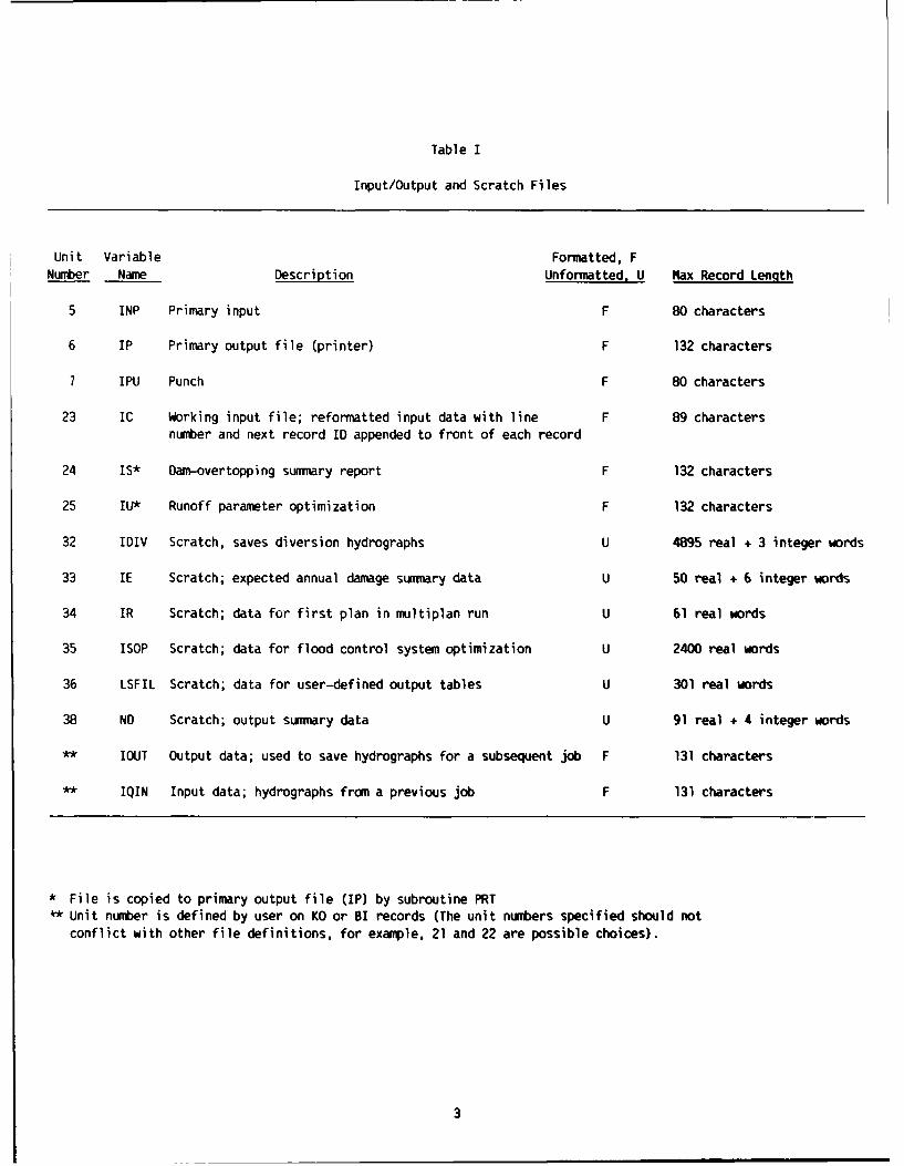
Table I
Input/Output and Scratch Files
Unit Variable Formatted, F
Number Name Description Unformatted, U Max Record Length
5 INP Primary input F 80 characters
6 IP Primary output file (printer) F 132 characters
7 IPU Punch F 80 characters
23 IC Working input file; reformatted input data with line F 89 charactersnumber and next record ID appended to front of each record
24 is* Dam-overtopping summary report F 132 characters
25 IU* Runoff parameter optimization F 132 characters
32 IDIV Scratch, saves diversion hydrographs U 4895 real + 3 integer words
33 IE Scratch; expected annual damage summary data U 50 real + 6 integer words
34 IR Scratch; data for first plan in multiplan run U 61 real words
35 ISOP Scratch; data for flood control system optimization U 2400 real words
36 LSFIL Scratch; data for user-defined output tables U 301 real words
38 ND Scratch; output summary data U 91 real + 4 integer words
** IOUT Output data; used to save hydrographs for a subsequent job F 131 characters
** IQIN Input data; hydrographs from a previous job F 131 characters
* File is copied to primary output file (IP) by subroutine PRT1* Unit number is defined by user on KO or BI records (The unit numbers specified should not
conflict with other file definitions, for example, 21 and 22 are possible choices).
3
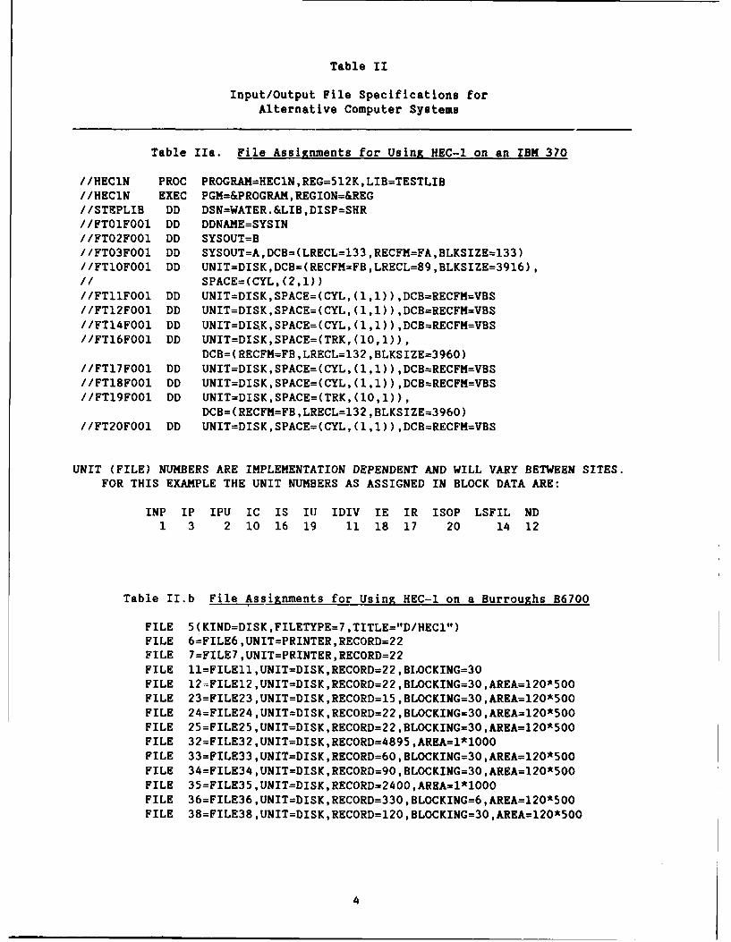
Table II
Input/Output File Specifications forAlternative Computer Systems
Table Iha. File Assignments for Using HEC-l on an IBM 370
//HEClN PROC PROGRAM=HEClN,REG=512K,LIB=TESTLIB/ /HEClN EXEC PGM=&PROGRAM, REGION=®/ /STEPLIB DO DSN=WATER.&LIB,DISP=SHR//FT0lFO0l DO DDNAME=SYSIN//FTO2FO0l DD SYSOUT=B//FTO3FOOl DO SYSOUT=A,DCB=(LRECL=133 ,RECFM=FA,BLKSIZE=133)//FTlOFO0l DO UNIT=DISK,DCB=(RECFM=FB ,LRECL=89,BLKSIZE=3916),
/1 SPACE=(CYL,(2,1))//FTllFO0l DO UNIT=DISK,SPACE=(CYL, (1,1)) ,DCB=RECFM=VBS//FT12FOOl DD UNIT=DISK,SPACE=(CYL, (1,1)) ,DCB=RECFM=VBS//FT14FO0l DO UNIT=DIS.K,SPACE=(CYL, (1,1)) ,DCB=RECFM=VBS//FT16FOO1 DD UNIT=DISK,SPACE=(TRK,(1O,1)),
DCB= (RECFM=FB ,LRECL=132 ,BLKSIZE=3960)//FTl7FO0l DD UNIT=DISK,SPACE=(CYL, (1,1)) ,DCB=RECFM=VBS//FTl8FOOl DD UNIT=DISK,SPACE=(CYL, (1,1)) ,DCB=RECFM=VBS//FTl9FO0l DD UNIT=DISK,SPACE=(TRK,(lO,1)),
DCB= (RECFM=FB ,LRECL=132 ,BLKSIZE=396O)//FT2OFOO1 DD UNIT=DISK,SPACE=(CYL, (1,1)) ,DCB=RECFM=VBS
UNIT (FILE) NUMBERS ARE IMPLEMENTATION DEPENDENT AND WILL VARY BETWEEN SITES.FOR THIS EXAMPLE THE UNIT NUMBERS AS ASSIGNED IN BLOCK DATA ARE:
INP IP IPU IC IS ITJ IDIV IE IR ISOP LSFIL ND1 3 2 10 16 19 11 18 17 20 14 12
Table II.b File Assignments for Using HEC-l on a Burroughs B6700
FILE 5(KIND=DISK,FILETYPE=7 ,TITLE="D/HECl1)FILE 6=FILE6 ,UNIT=PRINTER,RECORD=22FILE 7=FILE7 ,UNIT=PRINTER,RECORD=22FILE ll=FILEll ,UNIT=DISK,RECORD=22 ,B[.OCKING=30FILE 12 -FILE12,UNIT=DISK,RECORD=22,BLOCKING=3O,AREA=l20*5O0FILE 23=FILE23 ,UNIT=OISK,RECORD=15 ,BLOCKING=30,AREA=120*5O0FILE 24=FILE24 ,UNIT=DISK,RECORD=22,BLOCKING=30,AREA=120*500FILE 25=FILE25 ,UNIT=DISK,RECORD=22,BLOCKING=30,AREA=120*500FILE 32=FILE32 ,UNIT=DISK,RECORD=4895 ,AREA=1*10O0FILE 33=FILE33 ,UNIT=DISK,RECORD=60,BLOCKING=30,AREA=120*500FILE 34=FILE3A ,UNIT=DISK,RECORD=90,BLOCKING=30,AREA=120*500FILE 35=FILE35 ,UNIT=DISK,RECORD=2400,AREA=1*1000FILE 36=FILE36 ,UNIT=OISK ,RECORD=330 ,BLOCKING=6 ,AREA=120*500FILE 38=FILE38 ,UNIT=DISK ,RECORD=120 ,BLOCKING=30 ,AREA=12O*50
4

Table IIc. File Assignment for Using HEC-1 on a CDC
Place the following lines as the first record of FORTRAN program source code:
PROGRAM HEC1 (INPUT,OUTPUT,PUNCH,T AE5=INPUT,1 TAPE6=OUTPUT,TAPE7=PUNCH,TAPE21,TAPE22,TAPE23,TAPE24,2 TAPE25,TAPE32,TAPE33,TAPE34,TAPE35,TAPE36,3 TAPE38)
See Table I for unit numbers corresponding to TAPE5 through TAPE38. Forexample, TAPE5 corresponds to unit number 5, variable INP, and TAPE38corresponds to unit number 38, variable ND.
Table IId. File Assignments for Using HEC-l on a Harris 500
AS 5 = Input File formatted file
AS 6 = Output File "
AS 7 = Punch File "
AS 23 = Wl formatted work file
AS 24 = W2 "
AS 25 = W3 t
AS 32 = U2 unformatted work file
AS 33 = U3
AS 34 = U4
AS 35 = U5
AS 36 = U6 t
AS 38 = U8
5
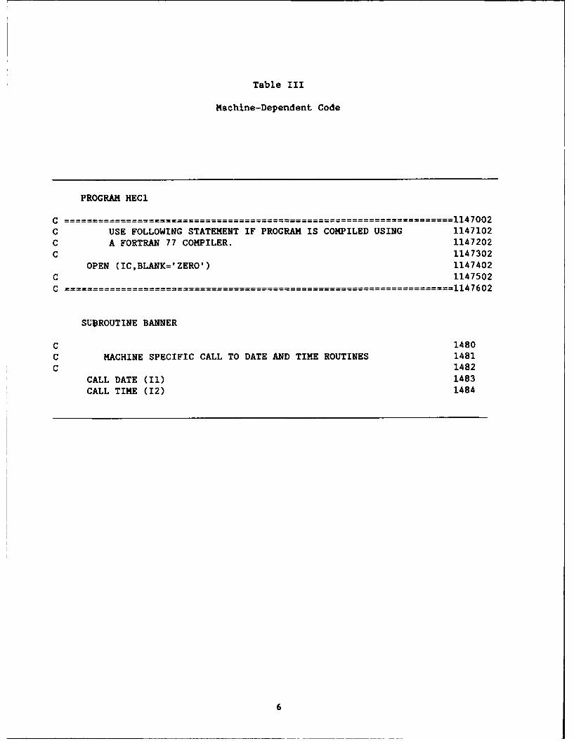
Table III
Machine-Dependent Code
PROGRAM HEC1
C- - - - - - - - - - - - - - 1147002C USE FOLLOWING STATEMENT IF PROGRAM IS COMPILED USING 1147102C A FORTRAN 77 COMPILER. 1147202C 1147302
OPEN (IC,BLANK= ZERO') 1147402C 1147502C 1147602
SUBROUTINE BANNER
C 1480C MACHINE SPECIFIC CALL TO DATE AND TIME ROUTINES 1481C 1482
CALL DATE (I1) 1483CALL TIME (12) 1484
6

2.7 Data Storage System - DSS
The HEC Data Storage System is not currently available for general distri-bution. Consequently, an HEC-1 dummy routine, DSMSTR, is used in place of theroutines available to Corps users for accessing DSS. Absence of these routinesor the presence of the dummy DSMSTR does not have any computational effect onprogram execution.
3.0 ERROR MESSAGES
The HEC-1 Users Manual (Section 11, Table 11.1) lists error messages whichwill print, along with an explanation of the message. Some errors will notcause the program to stop execution, so the user should always check the outputfor possible errors or warnings. The array dimensions listed in Table IV arethose used by HEC on a CDC Cyber 865 computer, and correspond to the officialHEC-distributed version of the program. Other dimensions may be used as notedin the following section on Memory Management. If the dimensions are changed,the dimension-error checks should also be changed in the source code.
The computer operating system may also print error messages. When an erroroccurs, the user should first ascertain if it is generated by HEC-1 or by thesystem. If it is generated by HEC-1, i.e., in the format given in the UsersManual, that table should be referred to and the indicated actions taken. Ifthe error is system generated, the computer center user service and/or the in-house computer systems personnel should be contacted to ascertain the meaningof the error. These errors may be due to incorrectly input or read data,errors in HEC-1, or the computer system. If these system errors cannot beresolved in-house or if there appears to be an error in the HEC-1 program, theHEC should be contacted.
4.0 COMPUTER MEMORY MANAGEMENT
4.1 Changing Dimensions
Computer memory requirements can be reduced by decreasing the dimensionsof some arrays. Table IV identifies the arrays whose dimensions have the mostimpact on core storage. Because of the error checks on dimensions (seeprevious section) and for ease of making changes, the dimensions are specifiedas variables.
To change a dimension, both the dimension-size variable and the arraysthemselves must be changed. Table IV shows both the dimension-size variablesand the arrays in which the particular dimension occurs. The labeled commonblock or subroutines in which the array occurs is also identified. Note thatmany of the dimensions are a function of other dimension statements. Theamount of reduction in a dimension will be dependent upon the options and thesizes desired by the user.
Pay special attention to arrays which occur in EQUIVALENCE statements.
4.2 Deleting Subroutines
Computer memory requirements can also be reduced by eliminating somesubroutines. The subroutines required for various HEC-1 simulation optionsare shown in Table V. The memory reduction obtained from deleting subroutinesmay not be significant if an overlay is used.
7

Table IV
Array Dimensions
ArrayVariable Name/Definition Size Limit Arrays Location
KQ Hydrograph ordinates 300 DEWPT,EXCSR,EXCSS,ITLS COMHON/ORDTS/KDAY,KHOUR,KHON,PRCP,PRCPR,Q,QO,RAINA,SNMT,SOL,STG,STR,TMPR,WIND
KR Recording precip gages 15 PRCPR COMMON/ORDTS/
ISTAR CONHON/PRECIP!
KQH' PLAN/RATIO hydrograph 4800 QH,QK COMMON/HULTQ/ordinates
KUHGQ Unit graph ordinates 150 QUNGR,QCLK COMHON/UNITGR/
KN Non-recording gages 70 ANAPN,ISTAN COMHON/PRECP/
KHlN Non-recording gage 10 ISTN,WTN COMMON/PRECP/weighting
KHR Recording gage weighting 5 ISTR,WTR COMMON/PRECP/
KZOtIE Snowmelt zones 10 ANAP,ANDAY,AREA,CUML, CONMON/SNOWZ/SNO, SNOW
KSTM Depth-area precip array 9 AX,BX,CX,DX,STRM,TRDA COMHON/HULTPS/
KRTIO Flood/precip RATIOS 9 RTIO COMHON/HULTPS/
FREQ ,PFRQ COMHON/ECON2/
QPREP SUBROUTINE ECONO
LCM2 Internal Random Access 24025 SAVE CO1QMON/RAND/Array
1KQH should be the lesser of 2*KRTIO.KQ or 4800
2 LC = 5.(KQH+5)
8

4.3 Overlayin. Subroutines
Computer memory requirements can also be reduced by overlaying subroutines.
A suggested overlay structure is given in Table VI. That overlay structure
was successfully used to implement the program on a Harris 100 computer with
64k (decimal) words of central memory.
The overlay structure details which subroutines must be in memory at the
same time during execution by a root path. The path is described by the letter
code given in Table VI. For example, the MAIN ROOT connects with high level
sub-roots A, B, C, D, E, F, G, or H. The sub-roots connect with lower level
roots. For example, sub-root B connects with BI, B2, B3, B4,"or B5. This root
heirarchy may he continued to lower sub-root levels. For example, a root path
may consist of F, F3, F3B and either F3Bl, F3B2, F3B3, F3B4, or F3B5. All the
subroutines that are part of any root path must be in memory at the same time.
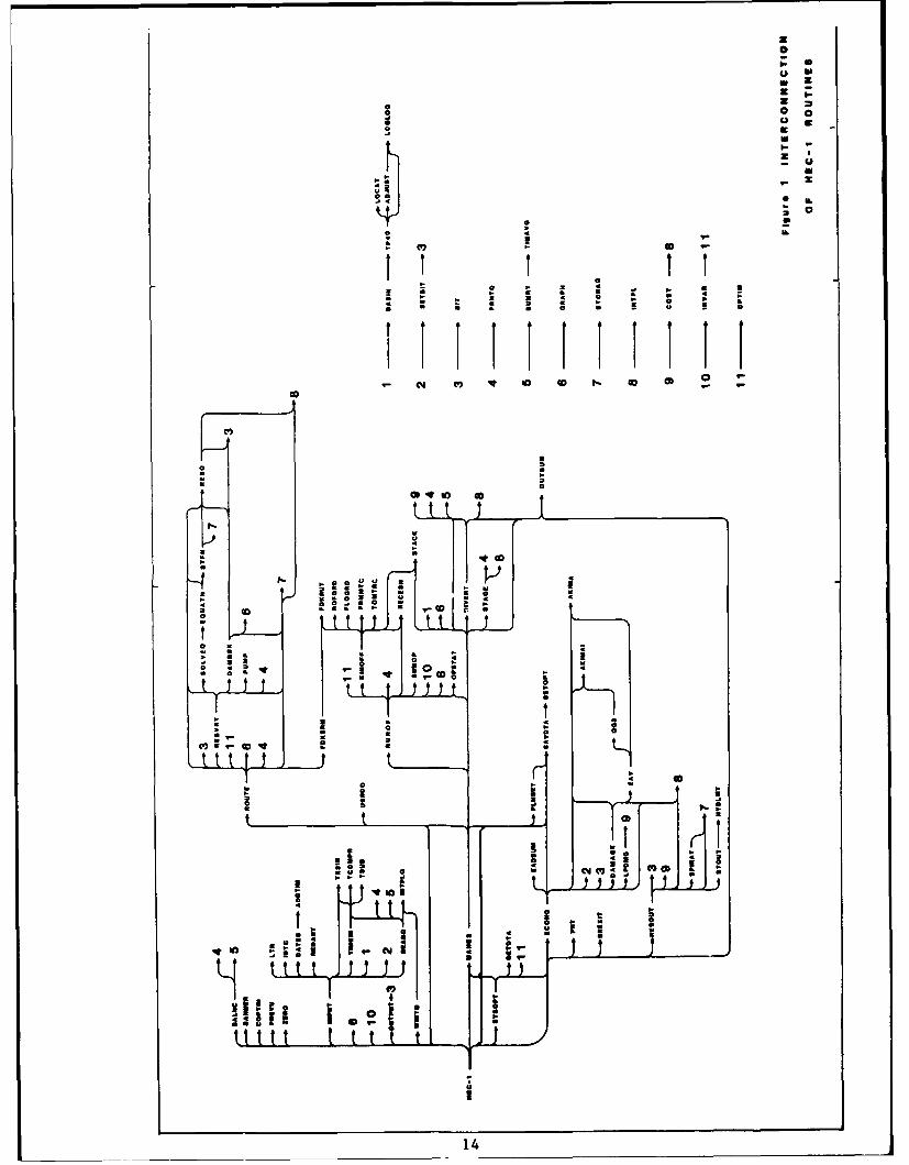
5.0 PROGRAM STRUCTURE
The HEC- 1 computer program consists of a main routine and 67 subroutines.The interlinkage of the subroutines is shown in Figure 1. A brief description
of each subroutine is given in Table VII.
9

Table V
Required Subroutines for HEC-l Simulation Options
Simulation options
1 All jobs2 Runoff parameter optimization3 Routing parameter optimization4 Stream network5 Multiplan-multiratio6 Economics7 System optimization8 Stream network with dam break9 Stream nework with kinematic wave10 Stream network with DSS11 Economic model with DSS
X required subroutines* subroutine occasionally used, depends on input option
t subroutines needed for DSS (Corps users only)
Options1 2 3 4 5 6 7 8 9 10 11
-- ---- -------------------------------------SubroutinelHECI X X X X X X X X X X XADDTIM X X X X X X X X X X XADJUST * * * * * * * *AKIMA X XAKIMAI X XBALNC *BANNER X X X X X X X X X X XBASIN X X x X X X K XBIT X X X X X X X X X X XCHNPRC * * * * * * * *CKPRNMt x xCOPYIN X X X X X X X X X X XCOST XDAMAGE X XDAMBRK XDATES X X X X X X X X X XDIVERT X X X X X K XDSHSTR X X X X X X X X X X XEADSUM X XEAV X xECONO X XEQUATN I* * * X * * *EREXIT x X X X X X X x X X XFDKRUT XFDKSRM XFLOGRD XFRNNTC XGETDTA XGRAPH x X X x x x X x X x XHYDLET * * * * X * * *
10
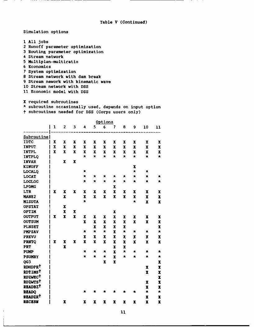
Table V (Continued)
Simulation options
I All jobs2 Runoff parameter optimization3 Routing parameter optimization4 Stream network5 Multiplan-multiratio6 Economics7 System optimization8 Stream network with dam break9 Stream nework with kinematic wave10 Stream network with DSS11 Economic model with DSS
X required subroutines* subroutine occasionally used, depends on input optiont subroutines needed for DSS (Corps users only)
Options1 2 3 4 5 6 7 8 9 10 11
--- -----------------------------------------SubroutinelIDTC X x x x x x x X x x xINPUT x X X X X X X X X X XINTPL X x x x x x x x x x xINTPLQ * * * * * * * *INVAR X xKINOFF XLOCALQ * * *LOCAT * * * * * * * *LOGLOG * * * * * * * *LPDMG XLTR x x x x x x x x x x xMANE2 X X X X X X I XMISDTA * * I XOPSTAT XOPTIM X X IOUTPUT X x x x X x x X x x xOUTSUM X X X X X X XPLNSET X I X XPMPSAV * * * X * * * *PREVU X x X X X X XPRNTQ X X X X X X X X X X XPRT X XPUMP * * * X * * * *PSUMRY * * * X * * * *QG3 x x xRDHDPRt X XRDTIKSt x xRDZWECt xRDZWTSt X xREADBZt X XREADQ I* * * * * * * *
RKADZRt x xRECESN X X X X X x X X X
11
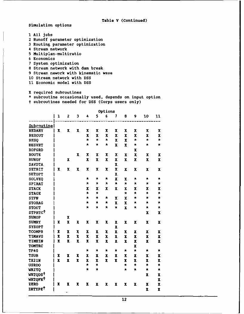
Table V (Continued)Simulation options
1 All jobs2 Runoff parameter optimization3 Routing parameter optimization4 Stream network5 Nultiplan-multiratio6 Economics7 System optimization8 Stream network with dam break9 Stream nework with kinematic wave10 Stream network with DSS11 Economic model with DSS
X required subroutines* subroutine occasionally used, depends on input option
t subroutines needed for DSS (Corps users only)
Options
1 2 3 4 5 6 7 8 9 10 11
----- ------------------------------------SubroutinelREDARY X X X X X X X X X X XRESOUT X X X X X X XRESQ * * * X X * * *RESVRT * * * X X * * *
ROFGRD XROUTE X X X x X X X XRUNOF X X X X X X I XSAVDTA xSETBIT x x x x x x x x x x xSETOPT XSOLVEQ * * * x I * * *SPIRAT * * * * * * * *STACK X X X X X X XSTAGE * * * * * *STFN * * * X X * * *STORAG * * * X I * * *STOUT * * * * X * * *STPRTCt X XSUMOP XSUMRY x x x x x x x x x x xSYSOPT XTCOMPR X X X X X I X X X X XTIMAVG X X X X X X X X X X XTIHEIN x x x x x X x x x x xTOMTRC XTP40 * * * * * * * *TSUB X X X x X X X X X X XTX2IN x x X X X x X X X X XUSRDO * * * * * *WRITQ * * * * * *WRTQDSt X XWRTQFRt xZERO X x X X X X X X X X XZRTYPEt X x
12
Table VIOverlay Structure
IMain Root I ®BANNER COPYIN PREVU PRT ZERO
DSMSTR I I DATES ADDTIMIEREXIT IBIT I===~=----OPTIM IIDTC I }TIMEIN TX21NSAVDTA IINPUT ====
SETOPT ILTR I ADJUST BASIN LOCAT LOGLOG TP40SYSOPT IREDARYI==---------------
IUSRDO I SERBIT 1I B4 INTPLQ PRNTQ READQ SUHRY TIMAVGITCOMPR == -- - - - - - - - - - -
ITSUB 04 M~ ISDTA CKPRNM RDHDPR RDTIMS RDZWTSII READBZ READZR STPRTC ZRTYPE
1IT OUTPUT
IBIT RESOUT DAMBRK IDl HYDL.MT STOUTI COST RESQ GRAPH I-------IINTPL STORAG ID2 SPIRAT
I(® BALNC PRNTQ STACK SU14RY TIMAVG
II DIVERT COST INTPLQ GRAPHI (j~LOCALQ MISDTA OUTSUMII SUMRY TIMAVG WRITQ
I I I ]2 COSTI I ~~ ~ =--------------------
I IBIT I 2 j FDKRUT FDKSRM(F) I ROUTE I==-------------------
III[2C] DAMBRK PUMP RESQ RESVRT PHPSAV PSUNRYIII SOLVEQ EQUATtI STFN STORAG TIMAVG OUTSUM
INTPL I I 3A INVAR OPSTAT SUMOPI
PRNTQ Ei I ~BFRMHTCIISTACK IRECESN I=2- -
I IRUNOF I j3]J I 3B]J FLOGRD
I II IKINOFF I j3B] ROFGRD
I I I I 3B]I TOMTRC
III I3B~ FDKRUT I
III BASIN ADJUST LOCAT LOGLOG TP40
I3STAGEI
I I I~jPLNSETI
I0 IIBIT WRTQDS
I I @8 GRAPHI
I I ®AKIMA AKINAI BIT COST DAMAGE EADSUM EAVIIECONO INTPL LPDMG QG3 SETBIT RDZWEC WRTQFR
I I®K-GETDTAI2222U2 U 22213
Z0
a Zz6
a 000go 0o
a In
o -0 0 a
I- 7
r~ W4
00a
C',i .-t t t*
t t tt t t t t i
o 14

Table VII
Description of HEC-1 Subroutines
HEC1 - initialization, control program flow
ADDTIM - adds one-time interval to current time
ADJUST - computes depth-area adjustment for hypothetical storm
AKIMA - finds coefficients for cubic spline
AKIMAI - cubic spline interpolation
BALNC - computes balanced hydrograph
BANNER - prints program banner
BASIN - computes basin-average rainfall; standard project storm; pro'ablemaximum storm; weighting of gaged rainfall
BIT tests a bit in an integer variable
CHNPRC - computes channel loss
CKPRNM - checks parameter name for DSS variables against known parameters
COPYIN - copies input data to working file; adds identification of next recordto beginning of each record; converts data from free format to fixedformat
COST - computes cost of a project element
DAMAGE - computes damage-frequency relation
DAMBRK - computes dam-breach size; sets time step for breach calculation;prints dam-break sumary
DATES - computes date and time for each hydrograph ordinate
DIVERT - diverts flows; retrieves diversion hydrographs
DSMSTR - controls use of DSS
EADSUM - prints summary of expected annual damages
EAV - computes expected annual damage
ECONO - reads data for expected annual da~age calculation
EQUATN - equations which require iterative solution
EREXIT - prints number of errors; exits program on error
15

Table VII (Continued)
FDKRUT - finite difference solution of kinematic wave routing
FDKSRK - routes flows using kinematic wave method
FLOGRD - computes distance step for kinematic wave routing of runoff hydrographin collector and main channels
FRMHTC - converts excess from metric to English units
GETDTA - gets data to compute plan 2 for flood-contol system optimization
GRAPH - makes printer plots of hydrographs
HYDLMT - computes hydraulic characteristics from cross-section data
IDTC - compares next record identification code with current recordidentification code
INPUT - reads input data from working file
INTPL - linear interpolation
INTPLQ - interpolates a hydrograph from one interval to another
INVAR - initializes variables for runoff parameter or routing parameteroptimization
IINOFF - transforms rainfall excess to cunoff using kinematic wave
LOCALQ - computes local flow hydrograph
LOCAT - generates position in triangular distribution for hypothetical storm
LOGLOG - log-log interpolation
LPDMG - computes flow/stage-damage relation for current local protection level
LTR - finds position of record identification code in array of valid letters
MANE2 - directs program to desired operation; combines hydrographs
MISDTA - tests a variable for a value indicating missing data
OPSTAT - computes statistics for comparing two hydrographs
OPTIK - controls variation of parameters being optimized
OUTPUT - prints input data
OUTSUM - prints final hydrograph sumary
PLNSET - sets variable for computing remaining plans after all input data hasbeen read for a station
16

Table VII (Continued)
PMPSAV - saves pumpflow hydrographs
PREVU - prints schematic diagram of stream system; sets up table for user-defined output
PRNTQ - prints hydrographs
PRT - copies summary table produced by subroutines DAMBRK and SUMOP fromscratch files to printer
PSUMRY - saves pumpflow values for summary printout
PUMP - computes pump flow
QG3 - three point gaussian quadrature
RDHDPR - reads HYDPAR data from DSS
RDTIMS - reads time series data from DSS
RDZWEC - reads ZW record for flow-frequency data
RDZWTS - reads ZW record for hydrologic time series
READBZ - reads BZ record
READQ - reads a hydrograph from a file
READZR reads ZR record
RECESN - adds base flow to direct runoff hydrograph
REDARY - reads table data (elevation, flow, storage, etc.)
RESOUT - computes spillway flow from weir coefficients; computes storage-outflow table from storage-elevation and outflow-elevation tables
RESQ - computes flow from reservoir for given elevation
RESVRT - routes flow through reservoir using level-pool routing
ROFGRD - computes time and distance step size for kinematic wave routing ofrainfall excess
ROUTE - routes flows using Muskingum, modified Puls, or straddle-staggermethods; optimizes Muskingum K and X
RUNOF - computes unit hydrograph; precipitation excess; transforms excess to
direct runoff
SAVDTA - saves data for computing plan 2 for flood-control system optimization
SETBIT - sets a bit in an integer variable
17

Table VII (Continued)
SETOPT - sets variable to be optimized
SOLVEQ - iterative solution algorithm using combination of secant method andinterval halving
SPIRAT - computes flow from ogee spillway
STACK - stores and retrieves hydrographs
STAGE - converts flows to stages
STFN - computes change in storage plus inflow minus outflow (continuity) forgiven elevation for reservoir routing
STORAG - computes reservoir storage from surface area and elevation data
STOUT - computes storage-outflow-elevation table for modified Puls routingfrom eight-point cross-section
STPRTC - sets part C of DSS pathname; saves parameter name
SUMOP - prints summary of runoff parameter optimization
SUMRY - computes summary of a hydrograph computation
SYSOPT - controls optimization of flood-control system components
TCOMPR - compares two times in internal form
TIMAVG - computes average values for a time series
TINEIN - reads time series data; interpolates to computation interval
TOHTRC - converts runoff hydrograph from English to metric units
TP40 - computes rainfall distribution for hypothetical storm
TSUB - subtracts two times in internal form
TX2IN - converts external time (day, month, year, hour) to internal time(year, day, minute)
USRDO - prints user-defined output tables
WRITQ - writes a hydrograph to a file
WRTQDS - writes a hydrograph to DSS
WRTQFR - writes flow-frequency data to DSS
ZERO - initializes variables for a new job
ZRTYPE - gets replacement record type from a ZR record
18