u.s. department diesel exhaust forest service emission ... · pdf filediesel emission exhaust...
TRANSCRIPT
U.S. Departmentof Agriculture
Forest Service
National Technology &Development Program
5100—Fire Management0851 1816—SDTDCDecember 2008
FOREST SERVICE
DEP A RTMENT OF AGRICU L T UR
E
Diesel Exhaust Emission System Temperature Test

Information contained in this document has been developed for the guidance of employees of the U.S. Department of Agriculture (USDA) Forest Service, its contractors, and cooperating Federal and State agencies. The USDA Forest Service assumes no responsibility for the interpretation or use of this information by other than its own employees. The use of trade, firm, or corporation names is for the information and convenience of the reader. Such use does not constitute an official evaluation, conclusion, recommendation, endorsement, or approval of any product or service to the exclusion of others that may be suitable.
The U.S. Department of Agriculture (USDA) prohibits discrimination in all its programs and activities on the basis of race, color, national origin, age, disability, and where applicable, sex, marital status, familial status, parental status, religion, sexual orientation, genetic information, political beliefs, reprisal, or because all or part of an individual’s income is derived from any public assistance program. (Not all prohibited bases apply to all programs.) Persons with disabilities who require alternative means for communication of program information (Braille, large print, audiotape, etc.) should contact USDA’s TARGET Center at (202) 720-2600 (voice and TDD). To file a complaint of discrimination, write USDA, Director, Office of Civil Rights, 1400 Independence Avenue, S.W., Washington, D.C. 20250-9410, or call (800) 795-3272 (voice) or (202) 720-6382 (TDD). USDA is an equal opportunity provider and employer.
Diesel Exhaust Emission System Temperature Test
Ralph H. Gonzales, Mechanical Engineer
San Dimas Technology & Development CenterSan Dimas, California
December 2008

v
Table of Contents
Table of ConTenTs
Executive Summary .................................................................................. 1
Introduction ............................................................................................... 3
Methodology ............................................................................................. 4
Test Limitations ......................................................................................... 7
Diesel Emission Exhaust Treatment System ............................................ 8
Ignition Temperatures of Forest Fuels ...................................................... 9
Modes of Ignition and Exhaust System Temperatures ........................... 10
Direct Contact with Hot Exhaust Surfaces .............................................. 11
Exhaust Gas Temperatures .................................................................... 13
Ignition of Accumulated Debris ............................................................... 14
Cooling Characteristics ........................................................................... 15
Temperature Proximity Test .................................................................... 16
Conclusions ............................................................................................ 17
Recommendations .................................................................................. 17
Acknowledgements................................................................................. 18
Appendix A—Test Data and Results
Dodge 5500 HD .............................................................................. 19
Ford F-550 ...................................................................................... 23
GMC C5500 .................................................................................... 26
International .................................................................................... 29
Sterling ............................................................................................ 32
Ford non-DPF ................................................................................. 34
Appendix B—Diesel Exhaust Treatment Systems .................................. 35
Literature Cited ....................................................................................... 38

1
exeCuTive summary Diesel trucks—starting with the 2007 model year—used for on-highway applications are required to have an exhaust treatment system to reduce emissions, specifically large particulate matter. The diesel particulate filter (DPF) is a component of the system. DPFs are designed to physically filter particulate matter (soot). A regeneration process removes the accumulated soot from the filter. An internal DPF temperature in excess of 932 °F is required for this regeneration process. This report presents the results of an exploratory test designed to measure the temperature of system components and to determine whether the exhaust system surface temperature or gas temperature of new DPF-equipped vehicles can ignite light, flashy wildland fuels.
There have been anecdotal reports that wildland engines with DPF devices have started vegetation fires. Although the study was done from the perspective of wildland fire vehicles, the results apply to all DPF-equipped vehicles that may be operated in close proximity to light wildland fuels.
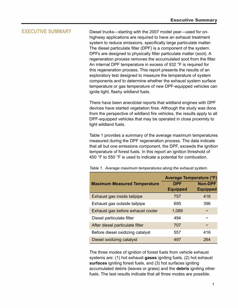
Table 1 provides a summary of the average maximum temperatures measured during the DPF regeneration process. The data indicate that all but one emissions component, the DPF, exceeds the ignition temperature of forest fuels. In this report an ignition threshold of 450 °F to 550 °F is used to indicate a potential for combustion.
Table 1. Average maximum temperatures along the exhaust system.
Average Temperature (°F)
Maximum Measured Temperature DPF Non-DPF Equipped Equipped
Exhaust gas inside tailpipe 757 416
Exhaust gas outside tailpipe 695 396
Exhaust gas before exhaust cooler 1,089 ~
Diesel particulate filter 494 ~
After diesel particulate filter 707 ~
Before diesel oxidizing catalyst 557 416
Diesel oxidizing catalyst 497 264
The three modes of ignition of forest fuels from vehicle exhaust systems are: (1) hot exhaust gases igniting fuels, (2) hot exhaust surfaces igniting forest fuels, and (3) hot surfaces igniting accumulated debris (leaves or grass) and the debris igniting other fuels. The test results indicate that all three modes are possible.
Executive Summary
2
Diesel Exhaust Emission System Temperature Test
Table 1 shows that the maximum exhaust gas and exhaust surface temperatures are around 500 °F and in some locations above 1,000 °F. Comparatively, on a non-DPF equipped vehicle, the maximum exhaust gas and surface temperatures of exhaust system components are at or below 416 °F. The data also indicate that ignition is not likely after the regeneration process is terminated; the exhaust gas and surface temperatures drop rapidly below the ignition threshold when the process is completed.
Temperature and contact time substantially influence the likelihood of combustion for forest fuels. At 550 °F, a contact time of 4 to 4.5 minutes can cause ignition for punky wood. At the same temperature, a contact time of over 10 minutes is needed to ignite cheatgrass. The regeneration process takes about 15 minutes.
To verify the ignition potential from vehicle exhaust systems, dead cheatgrass was exposed to the exhaust gases during regeneration and was observed to start smoking and show significant browning. Significant browning occurs when cheatgrass is exposed to temperatures around 518 °F for 5 minutes. Cheatgrass starts smoking at 572 °F (Kaminski 1934).
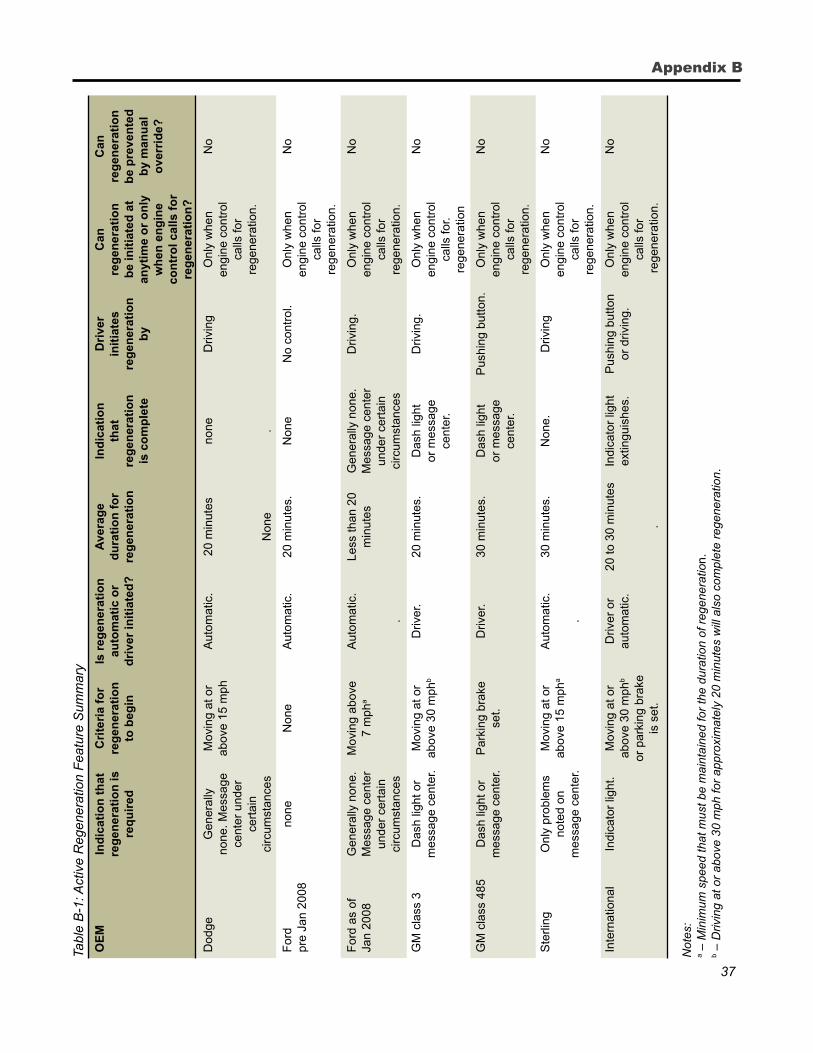
While it may seem that the temperature and contact time would be sufficient to cause ignition of light fuels, it is important to note that the regeneration process on most vehicles can be initiated only when the vehicle is moving. Extended contact time between the exhaust gases or surfaces and light surface fuels is likely limited for vehicles that require a minimum speed to start and maintain the regeneration process. However, there are some vehicles—such as the International and the GMC in the test sample—which the driver can place in regeneration mode while the vehicle is parked. Appendix table B1 provides a summary of DPF features. Systems which allow for stationary regeneration have a greater potential to ignite forest fuels. Ignition of accumulated forest fuels (debris) in exhaust-system pockets also poses a high risk as the accumulated debris is potentially combustible for either regeneration system. Even forest fuels with initially high moisture contents can dry and ignite.
The results of the exploratory study indicate that the regeneration process generates high temperatures in the exhaust system that creates the potential for the ignition of forest fuels. A more involved study is needed to provide statistically valid results. However, the results presented here warrant the following recommendations:
1. Inspect vehicle systems and remove all debris.
2. Avoid stationary regeneration around light flashy fuels.
3
Introduction
3. Inspect integrity of the exhaust system particularly the exhaust coolers. Repair leaks in exhaust systems.
inTroduCTion The San Dimas Technology and Development Center (SDTDC, of the Forest Service, U.S. Department of Agriculture) conducted an exploratory study on the temperatures associated with the exhaust systems of vehicles equipped with diesel particulate filters (DPF), specifically, the temperatures generated when the exhaust system is in regeneration mode. The objective of the study was to determine whether the exhaust gasses and exhaust surface temperatures during the regeneration process were high enough to ignite fine wildland fuels. To meet the study objective, the following questions needed to be answered:
1. What are the exhaust gas and exhaust system surface temperatures?
2. What are the hottest points on the exhaust system during the regeneration cycle of a DPF-equipped vehicle?
3. What are the temperatures around the DPF?
4. Are the temperatures hot enough to ignite wildland fuels?
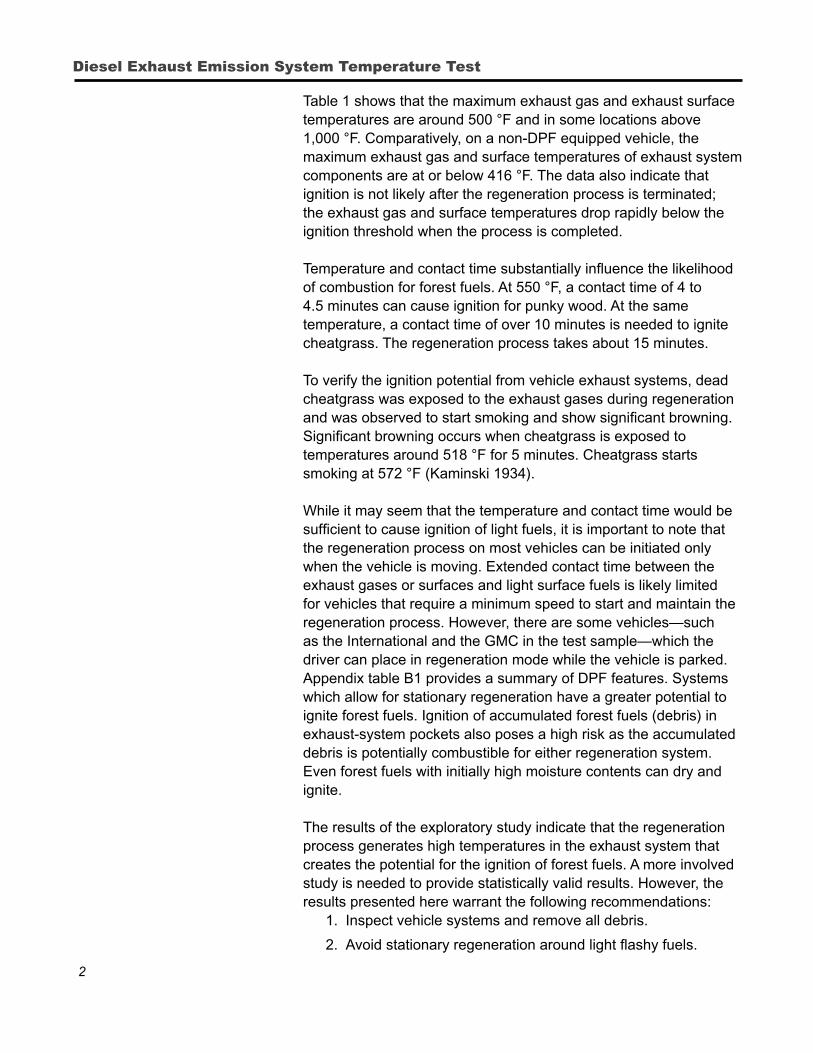
The exhaust systems on five vehicles equipped with DPFs were evaluated. A sixth vehicle (without a DPF) was tested for comparison. The following vehicles were selected because they are representative of the vehicle chassis used for wildland fire applications.
1. Dodge 5500 HD
2. Sterling 5500 Bullet
3. International 7400
4. Ford F-550
5. General Motors Corporation (GM) Model C5500
6. Ford F-550 (non-DPF)
Figure 1. DPF-equipped test vehicles.
4
Diesel Exhaust Emission System Temperature Test
For the purpose of this report, the terms “wildland fuels,” “ground cover,” or “light fuels” imply 1-hour fuels. One-hour fuels, such as grasses, leaves, mulch, and litter, have a diameter less than one-quarter inch and ignite at a temperature lower than other fuels when their moisture content is low.
meThodology There were three test components to this study: (1) exhaust gas and surface-temperature measurement, (2) temperature-proximity measurement, and (3) ground fuels ignition.
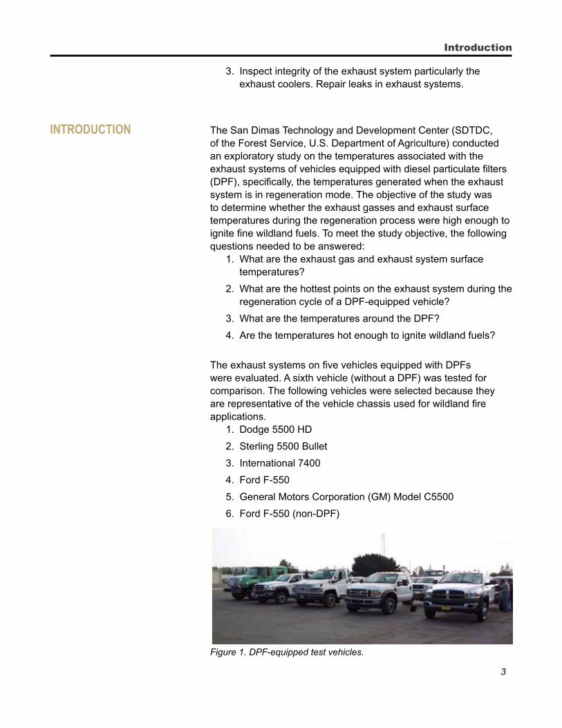
1. Exhaust gas and exhaust surface-temperature measurement. The vehicles were instrumented with K-type thermocouples that measure the surface and exhaust gas temperatures on different sections of the exhaust system. The thermocouples were connected to a data acquisition system programmed to collect data every 5 seconds. The manufacturer’s technicians verified that the latest engine-control software was loaded in the vehicle’s computer. The test vehicles were driven through a 7-mile loop and placed in regeneration mode at highway speeds. The vehicles were kept in regeneration mode after completing the test loop to measure temperatures while the vehicle was stationary. However, three out of five vehicles tested could not go into regeneration mode while stationary, so technicians overrode the programming to complete this test. Appendix table B1 provides a summary of DPF features for the test vehicles. Figures 2 through 4 show the test-instrumentation setup.
Figure 2. Data acquisition system.
5
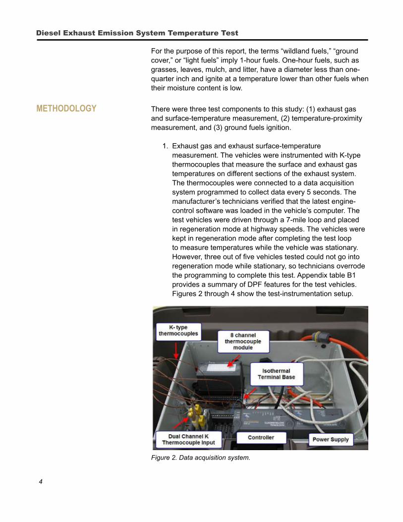
Figure 3. Placement of the exhaust gas thermocouple on the Ford F-550.
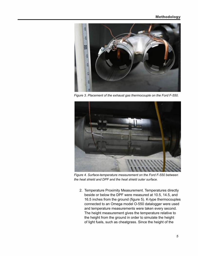
Figure 4. Surface-temperature measurement on the Ford F-550 between the heat shield and DPF and the heat shield outer surface.
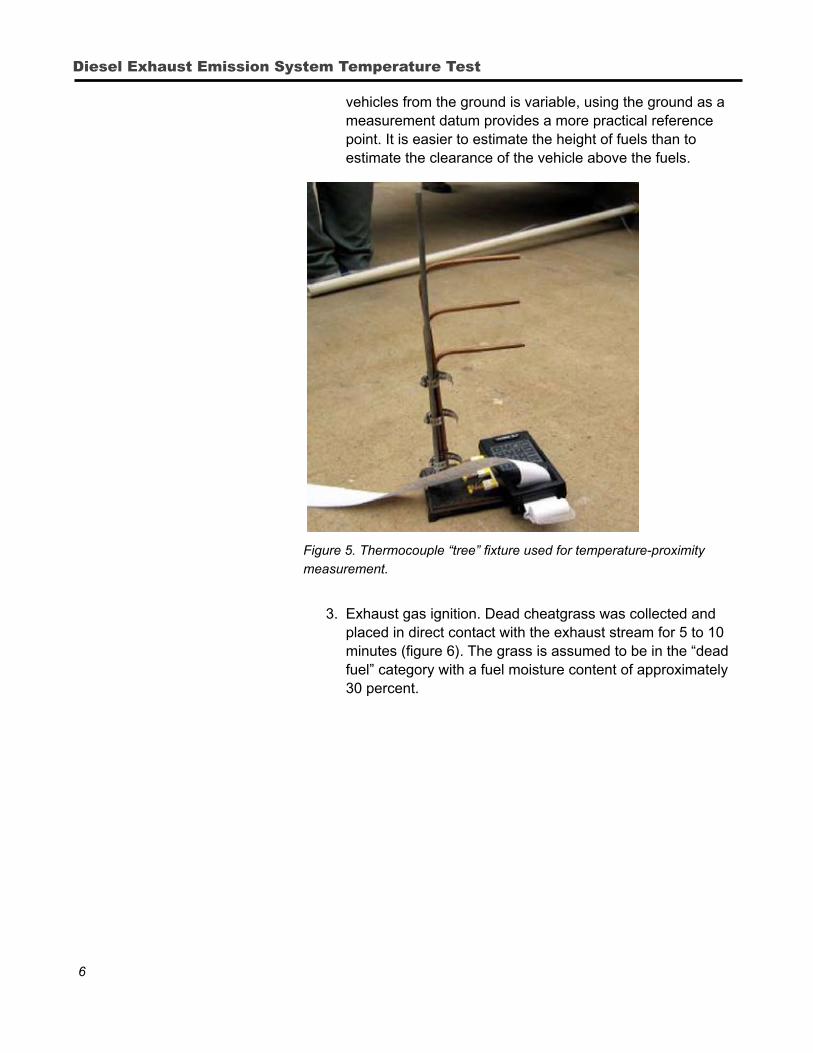
2. Temperature Proximity Measurement. Temperatures directly beside or below the DPF were measured at 10.5, 14.5, and 16.5 inches from the ground (figure 5). K-type thermocouples connected to an Omega model O-550 datalogger were used and temperature measurements were taken every second. The height measurement gives the temperature relative to the height from the ground in order to simulate the height of light fuels, such as cheatgrass. Since the height of the
Methodology
6
Diesel Exhaust Emission System Temperature Test
vehicles from the ground is variable, using the ground as a measurement datum provides a more practical reference point. It is easier to estimate the height of fuels than to estimate the clearance of the vehicle above the fuels.
Figure 5. Thermocouple “tree” fixture used for temperature-proximity measurement.
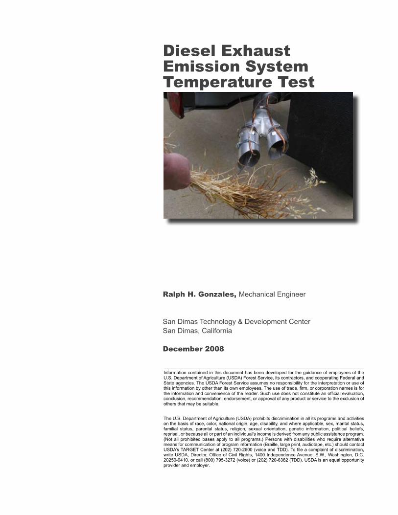
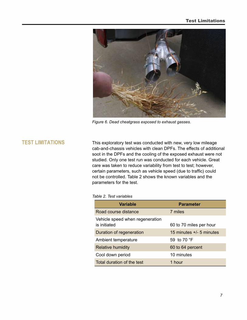
3. Exhaust gas ignition. Dead cheatgrass was collected and placed in direct contact with the exhaust stream for 5 to 10 minutes (figure 6). The grass is assumed to be in the “dead fuel” category with a fuel moisture content of approximately 30 percent.
7
Figure 6. Dead cheatgrass exposed to exhaust gasses.
TesT limiTaTions This exploratory test was conducted with new, very low mileage cab-and-chassis vehicles with clean DPFs. The effects of additional soot in the DPFs and the cooling of the exposed exhaust were not studied. Only one test run was conducted for each vehicle. Great care was taken to reduce variability from test to test; however, certain parameters, such as vehicle speed (due to traffic) could not be controlled. Table 2 shows the known variables and the parameters for the test.
Table 2. Test variables
Variable Parameter
Road course distance 7 miles
Vehicle speed when regeneration is initiated 60 to 70 miles per hour
Duration of regeneration 15 minutes +/- 5 minutes
Ambient temperature 59 to 70 °F
Relative humidity 60 to 64 percent
Cool down period 10 minutes
Total duration of the test 1 hour
Test Limitations
8
Diesel Exhaust Emission System Temperature Test
The quantity of particulate matter in the DPF affects the regeneration time, which in turn may affect exhaust temperature. During the test, the vehicles were in regeneration mode for 10 to 15 minutes. Manufacturers report a regeneration times up to 30 minutes. The regeneration cycle time varies depending on the manufacturer and the amount of accumulated soot. Appendix A contains data on the average duration of regeneration for the test vehicles.
Because the test vehicles were cab-and-chassis only, the exhaust systems were exposed. The cooling effect of this exposure is not known. The effect of elevated temperatures on surrounding body components is also unknown.
diesel emission exhausT TreaTmenT sysTem DPFs are emission-control devices designed to filter diesel
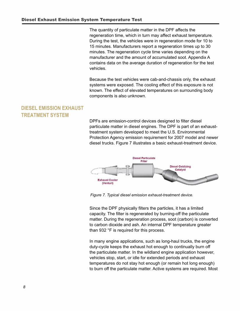
particulate matter in diesel engines. The DPF is part of an exhaust-treatment system developed to meet the U.S. Environmental Protection Agency emission requirement for 2007 model and newer diesel trucks. Figure 7 illustrates a basic exhaust-treatment device.
Figure 7. Typical diesel emission exhaust-treatment device.
Since the DPF physically filters the particles, it has a limited capacity. The filter is regenerated by burning-off the particulate matter. During the regeneration process, soot (carbon) is converted to carbon dioxide and ash. An internal DPF temperature greater than 932 °F is required for this process.
In many engine applications, such as long-haul trucks, the engine duty-cycle keeps the exhaust hot enough to continually burn off the particulate matter. In the wildland engine application however, vehicles stop, start, or idle for extended periods and exhaust temperatures do not stay hot enough (or remain hot long enough) to burn off the particulate matter. Active systems are required. Most
9
of these systems involve burning a small amount of diesel fuel in the exhaust stream to raise the temperature enough to burn away the particulate matter.
Manufacturers have estimated how often regeneration occurs. Sensors that monitor pressure and exhaust gas temperature calculate the amount of soot in the filter. Using the GM vehicle as an example, active regeneration occurs when 45 to 50 grams of soot are in the filter. GM predicts this will occur after:
n 22 hours of engine run time.
n 71 gallons of fuel consumption.
n 640 miles driven at sea level or 480 miles driven above 10,000 feet.
Regeneration occurs more often when an engine is operated at higher altitudes. The soot models used by manufacturers were developed for over-the-road applications. Prolonged idling, starting, and stopping contribute to soot build up, and a more frequent need for active regeneration. Appendix B discusses exhaust-treatment devices for diesel engines.
The DPF is not the only device that requires a higher temperature to function. The diesel oxidizing catalyst (DOC), similar to a catalytic converter in gasoline engines, requires at least 662 °F to function.
An exhaust cooler reduces the temperature of the exhaust gas before it exits the tailpipe. The exhaust cooler uses the Venturi principle to introduce ambient air into the exhaust stream, which is an effective mechanism for reducing temperatures in a short path. The Dodge and Sterling test units were not equipped with exhaust coolers.
igniTion TemperaTures of foresT fuels The ignition temperature of fine forest fuels is influenced by several
variables, such as fuel size, type, density, and moisture content. For forest fuels (in the absence of a pilot flame) the air temperature has been reported to be as low as 400 °F (Baxter 2004) and as high as 838 °F (Fairbanks and Bainer 1934). Ignition also depends on the contact time of the fuels to the high temperatures. Kaminski (1974) reports glowing combustion of punky wood at 626 °F with a contact time of 1.5 minutes and also at 518 °F with a contact time of 4 to 4.5 minutes. Nearly instantaneous ignition was reported at temperatures above 1,000 °F. Other research (Johnson et al. 1980, Babrauskas 2003) reported ignition temperatures from 482 °F to 536 °F.
Ignition Temperatures of Forest Fuels
10
Diesel Exhaust Emission System Temperature Test
The effect of wind is significant. Environmental-chamber tests indicate that a wind velocity of 2 miles per hour leads to fuel ignition at the lowest temperature. Cheatgrass starts burning at 760 °F in 1.3 minutes, while no ignition occurred with a wind velocity of 10 miles per hour above 830 °F (Harrison 1970). These results have implications on the ignition temperature when fuels are exposed to a high-velocity exhaust stream.
In this report an ignition threshold of 450 °F to 550 °F is used to signify an increased risk of ignition. This temperature range is between the ignition temperatures reported by other researchers. Some common forest fuels heated within or above this range have a high potential for ignition.
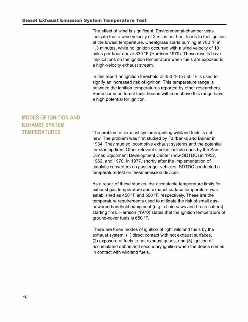
modes of igniTion and exhausT sysTem TemperaTures The problem of exhaust systems igniting wildland fuels is not
new. The problem was first studied by Fairbanks and Bainer in 1934. They studied locomotive exhaust systems and the potential for starting fires. Other relevant studies include ones by the San Dimas Equipment Development Center (now SDTDC) in 1952, 1962, and 1970. In 1977, shortly after the implementation of catalytic converters on passenger vehicles, SDTDC conducted a temperature test on these emission devices.
As a result of these studies, the acceptable temperature limits for exhaust gas temperature and exhaust surface temperature was established as 450 °F and 500 °F, respectively. These are the temperature requirements used to mitigate the risk of small gas-powered handheld equipment (e.g., chain saws and brush cutters) starting fires. Harrison (1970) states that the ignition temperature of ground-cover fuels is 650 °F.
There are three modes of ignition of light wildland fuels by the exhaust system: (1) direct contact with hot exhaust surfaces, (2) exposure of fuels to hot exhaust gases, and (3) ignition of accumulated debris and secondary ignition when the debris comes in contact with wildland fuels.
11
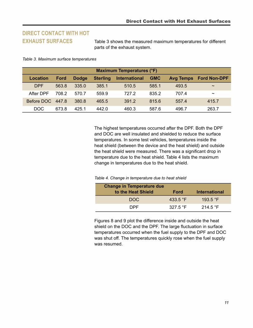
direCT ConTaCT wiTh hoT exhausT surfaCes Table 3 shows the measured maximum temperatures for different
parts of the exhaust system. Table 3. Maximum surface temperatures
Maximum Temperatures (°F)
Location Ford Dodge Sterling International GMC Avg Temps Ford Non-DPF
DPF 563.8 335.0 385.1 510.5 585.1 493.5 ~
After DPF 708.2 570.7 559.9 727.2 835.2 707.4 ~
Before DOC 447.8 380.8 465.5 391.2 815.6 557.4 415.7
DOC 673.8 425.1 442.0 460.3 587.6 496.7 263.7
The highest temperatures occurred after the DPF. Both the DPF and DOC are well insulated and shielded to reduce the surface temperatures. In some test vehicles, temperatures inside the heat shield (between the device and the heat shield) and outside the heat shield were measured. There was a significant drop in temperature due to the heat shield. Table 4 lists the maximum change in temperatures due to the heat shield.
Table 4. Change in temperature due to heat shield
Change in Temperature due to the Heat Shield Ford International
DOC 433.5 °F 193.5 °F
DPF 327.5 °F 214.5 °F
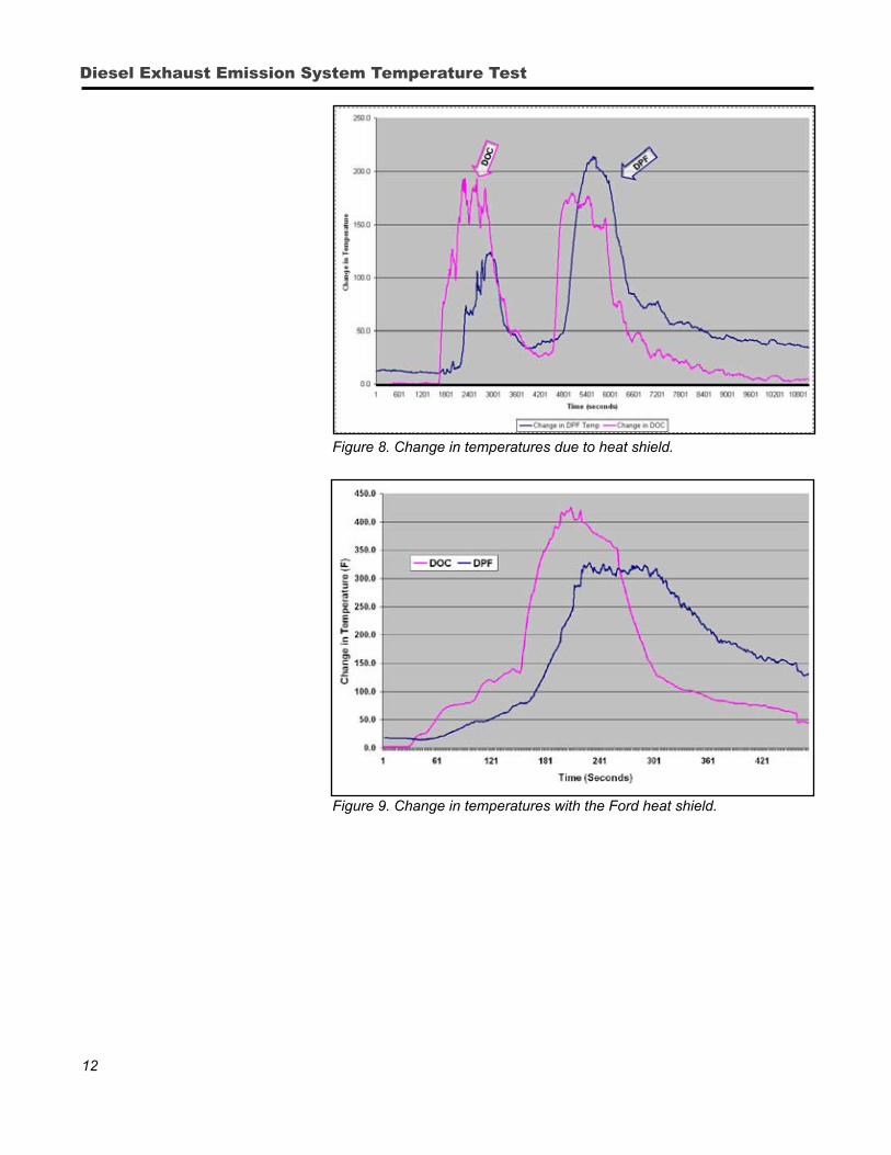
Figures 8 and 9 plot the difference inside and outside the heat shield on the DOC and the DPF. The large fluctuation in surface temperatures occurred when the fuel supply to the DPF and DOC was shut off. The temperatures quickly rose when the fuel supply was resumed.
Direct Contact with Hot Exhaust Surfaces
12
Diesel Exhaust Emission System Temperature Test
Figure 8. Change in temperatures due to heat shield.
Figure 9. Change in temperatures with the Ford heat shield.
13
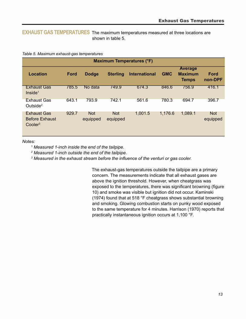
exhausT gas TemperaTures The maximum temperatures measured at three locations are shown in table 5.
Table 5. Maximum exhaust-gas temperatures
Maximum Temperatures (°F)
Average Location Ford Dodge Sterling International GMC Maximum Ford Temps non-DPF
Exhaust Gas 785.5 No data 749.9 674.3 846.6 756.9 416.1 Inside1
Exhaust Gas 643.1 793.9 742.1 561.6 780.3 694.7 396.7 Outside2
Exhaust Gas 929.7 Not Not 1,001.5 1,176.6 1,089.1 Not Before Exhaust equipped equipped equipped Cooler3
Notes: 1 Measured 1-inch inside the end of the tailpipe. 2 Measured 1-inch outside the end of the tailpipe. 3 Measured in the exhaust stream before the influence of the venturi or gas cooler.
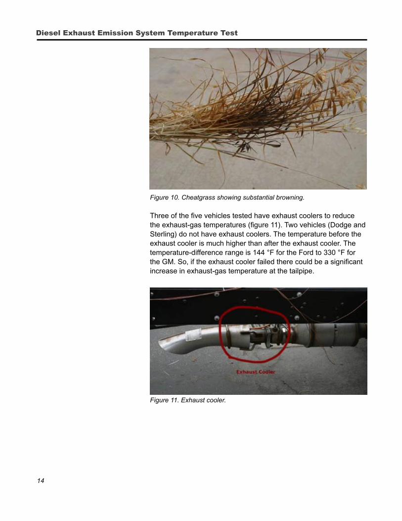
The exhaust-gas temperatures outside the tailpipe are a primary concern. The measurements indicate that all exhaust gases are above the ignition threshold. However, when cheatgrass was exposed to the temperatures, there was significant browning (figure 10) and smoke was visible but ignition did not occur. Kaminski (1974) found that at 518 °F cheatgrass shows substantial browning and smoking. Glowing combustion starts on punky wood exposed to the same temperature for 4 minutes. Harrison (1970) reports that practically instantaneous ignition occurs at 1,100 °F.
Exhaust Gas Temperatures
14
Diesel Exhaust Emission System Temperature Test
Figure 10. Cheatgrass showing substantial browning.
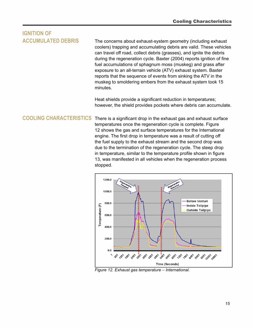
Three of the five vehicles tested have exhaust coolers to reduce the exhaust-gas temperatures (figure 11). Two vehicles (Dodge and Sterling) do not have exhaust coolers. The temperature before the exhaust cooler is much higher than after the exhaust cooler. The temperature-difference range is 144 °F for the Ford to 330 °F for the GM. So, if the exhaust cooler failed there could be a significant increase in exhaust-gas temperature at the tailpipe.
Figure 11. Exhaust cooler.
15
igniTion of aCCumulaTed debris The concerns about exhaust-system geometry (including exhaust
coolers) trapping and accumulating debris are valid. These vehicles can travel off road, collect debris (grasses), and ignite the debris during the regeneration cycle. Baxter (2004) reports ignition of fine fuel accumulations of sphagnum moss (muskeg) and grass after exposure to an all-terrain vehicle (ATV) exhaust system. Baxter reports that the sequence of events from sinking the ATV in the muskeg to smoldering embers from the exhaust system took 15 minutes.
Heat shields provide a significant reduction in temperatures; however, the shield provides pockets where debris can accumulate.
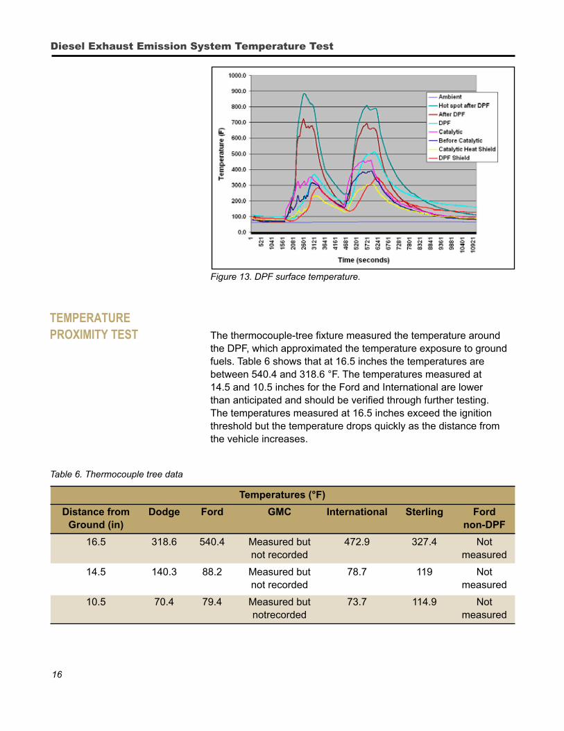
Cooling CharaCTerisTiCs There is a significant drop in the exhaust gas and exhaust surface temperatures once the regeneration cycle is complete. Figure 12 shows the gas and surface temperatures for the International engine. The first drop in temperature was a result of cutting off the fuel supply to the exhaust stream and the second drop was due to the termination of the regeneration cycle. The steep drop in temperature, similar to the temperature profile shown in figure 13, was manifested in all vehicles when the regeneration process stopped.
Figure 12. Exhaust gas temperature – International.
Cooling Characteristics
16
Diesel Exhaust Emission System Temperature Test
Figure 13. DPF surface temperature.
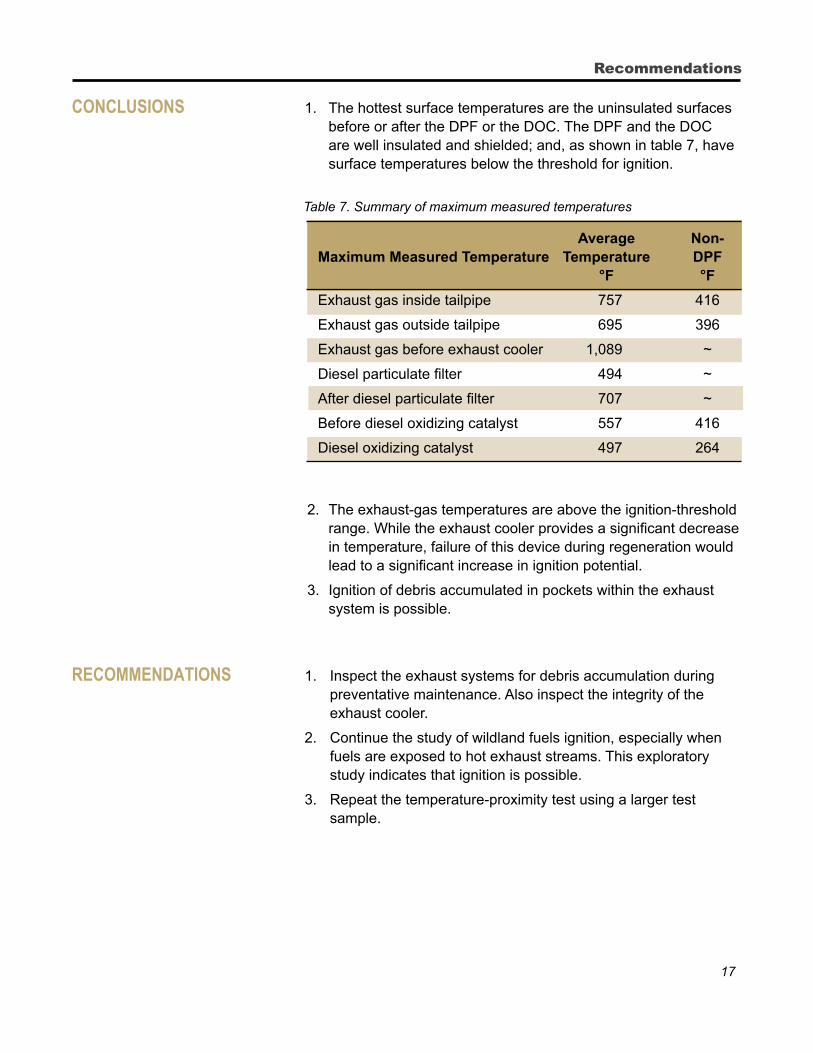
TemperaTure proximiTy TesT The thermocouple-tree fixture measured the temperature around
the DPF, which approximated the temperature exposure to ground fuels. Table 6 shows that at 16.5 inches the temperatures are between 540.4 and 318.6 °F. The temperatures measured at 14.5 and 10.5 inches for the Ford and International are lower than anticipated and should be verified through further testing. The temperatures measured at 16.5 inches exceed the ignition threshold but the temperature drops quickly as the distance from the vehicle increases.
Table 6. Thermocouple tree data
Temperatures (°F)
Distance from Dodge Ford GMC International Sterling Ford Ground (in) non-DPF
16.5 318.6 540.4 Measured but 472.9 327.4 Not not recorded measured
14.5 140.3 88.2 Measured but 78.7 119 Not not recorded measured
10.5 70.4 79.4 Measured but 73.7 114.9 Not notrecorded measured
17
ConClusions 1. The hottest surface temperatures are the uninsulated surfaces before or after the DPF or the DOC. The DPF and the DOC are well insulated and shielded; and, as shown in table 7, have surface temperatures below the threshold for ignition.
Table 7. Summary of maximum measured temperatures Average Non- Maximum Measured Temperature Temperature DPF °F °F
Exhaust gas inside tailpipe 757 416
Exhaust gas outside tailpipe 695 396
Exhaust gas before exhaust cooler 1,089 ~
Diesel particulate filter 494 ~
After diesel particulate filter 707 ~
Before diesel oxidizing catalyst 557 416
Diesel oxidizing catalyst 497 264
2. The exhaust-gas temperatures are above the ignition-threshold
range. While the exhaust cooler provides a significant decrease in temperature, failure of this device during regeneration would lead to a significant increase in ignition potential.
3. Ignition of debris accumulated in pockets within the exhaust system is possible.
reCommendaTions 1. Inspect the exhaust systems for debris accumulation during preventative maintenance. Also inspect the integrity of the exhaust cooler.
2. Continue the study of wildland fuels ignition, especially when fuels are exposed to hot exhaust streams. This exploratory study indicates that ignition is possible.
3. Repeat the temperature-proximity test using a larger test sample.
Recommendations
18
Diesel Exhaust Emission System Temperature Test
aCknowledgemenTs The following individuals were instrumental in the completion of the test and report.
SDTDC employees Armando Sanchez, Chris Bolz, Manuel Damole, Dave Haston, George Toyama, and Manuel Perez; General Services Administration employee John McDonald; and Los Angeles County Fire employee Mark Moser.
Manufacturer’s Representatives Ray Raz, General Motors Corporation; John Eder, Boise Mobile Equipment; and Dave Morse and Dale Neighbor, International Truck and Engine Corporation.
SDTDC thanks the following personnel for their technical review of the report: SDTDC employees David Haston, George Broyles, Sam Wu, and Armando Sanchez; Mike Arias, Forest Service Region 5; John McDonald, General Services Administration; Kirk Bradley, Roscommon Equipment Center; Daniel Yturriondobeitia, U.S. Department of the Interior, Bureau of Land Management; and Mark Moser, Los Angeles County Fire Department.
19
appendix a Appendix A presents the test data and results. In the analysis of the data, the data collected before going on the road course was not considered. Anomalies in the data, such as large temperature spikes for a short duration, were removed. For example, a 100 °F or more increase in surface temperature followed by a 100 °F or more drop is not physically possible and the data samples were removed. A 12-period moving average was used to analyze the data and facilitate trend analysis. The moving-average technique results in a “smoother” chart that is easier to view.
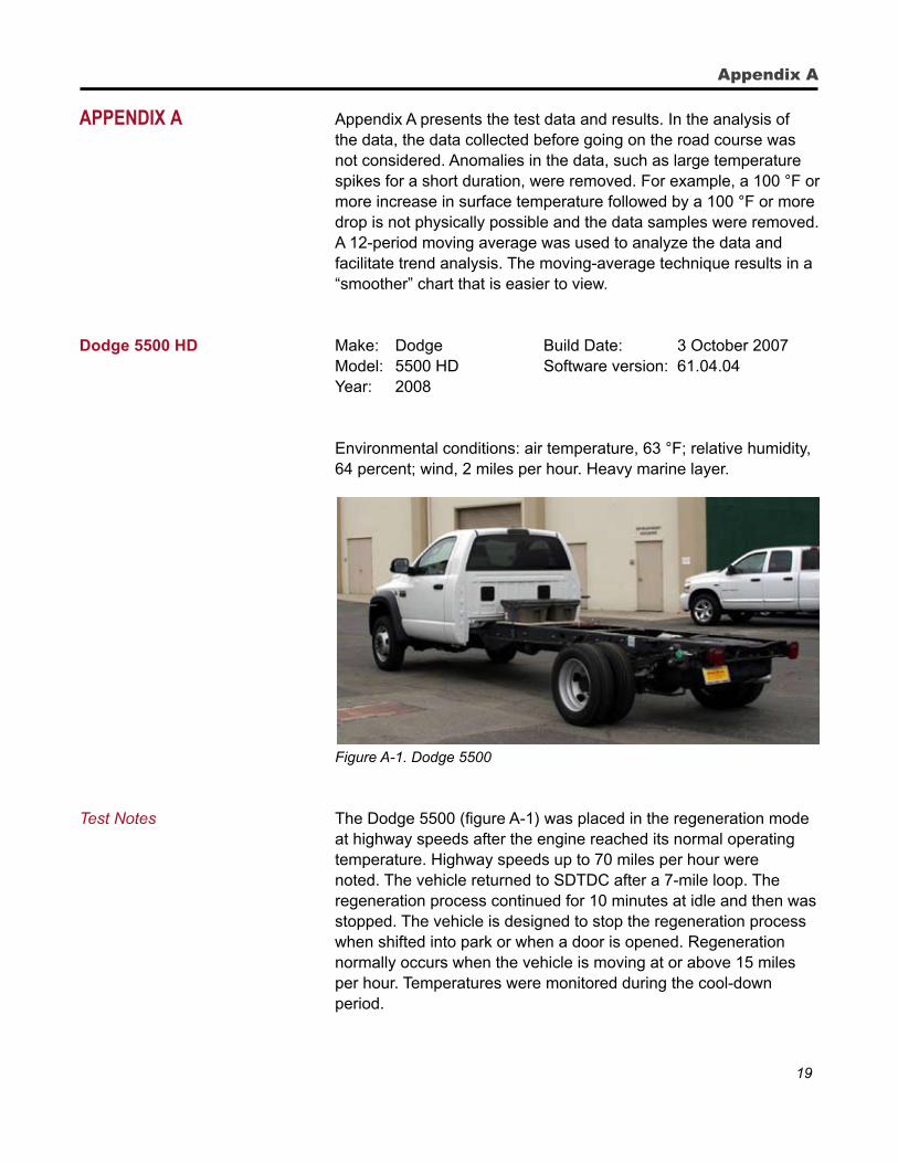
Dodge 5500 HD Make: Dodge Build Date: 3 October 2007 Model: 5500 HD Software version: 61.04.04 Year: 2008
Environmental conditions: air temperature, 63 °F; relative humidity, 64 percent; wind, 2 miles per hour. Heavy marine layer.
Figure A-1. Dodge 5500
Test Notes The Dodge 5500 (figure A-1) was placed in the regeneration mode at highway speeds after the engine reached its normal operating temperature. Highway speeds up to 70 miles per hour were noted. The vehicle returned to SDTDC after a 7-mile loop. The regeneration process continued for 10 minutes at idle and then was stopped. The vehicle is designed to stop the regeneration process when shifted into park or when a door is opened. Regeneration normally occurs when the vehicle is moving at or above 15 miles per hour. Temperatures were monitored during the cool-down period.
Appendix A
20
Diesel Exhaust Emission System Temperature Test
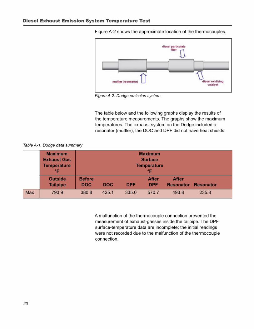
Figure A-2 shows the approximate location of the thermocouples.
Figure A-2. Dodge emission system.
The table below and the following graphs display the results of the temperature measurements. The graphs show the maximum temperatures. The exhaust system on the Dodge included a resonator (muffler); the DOC and DPF did not have heat shields.
Table A-1. Dodge data summary
Maximum Maximum Exhaust Gas Surface Temperature Temperature °F °F
Outside Before After After Tailpipe DOC DOC DPF DPF Resonator Resonator
Max 793.9 380.8 425.1 335.0 570.7 493.8 235.8
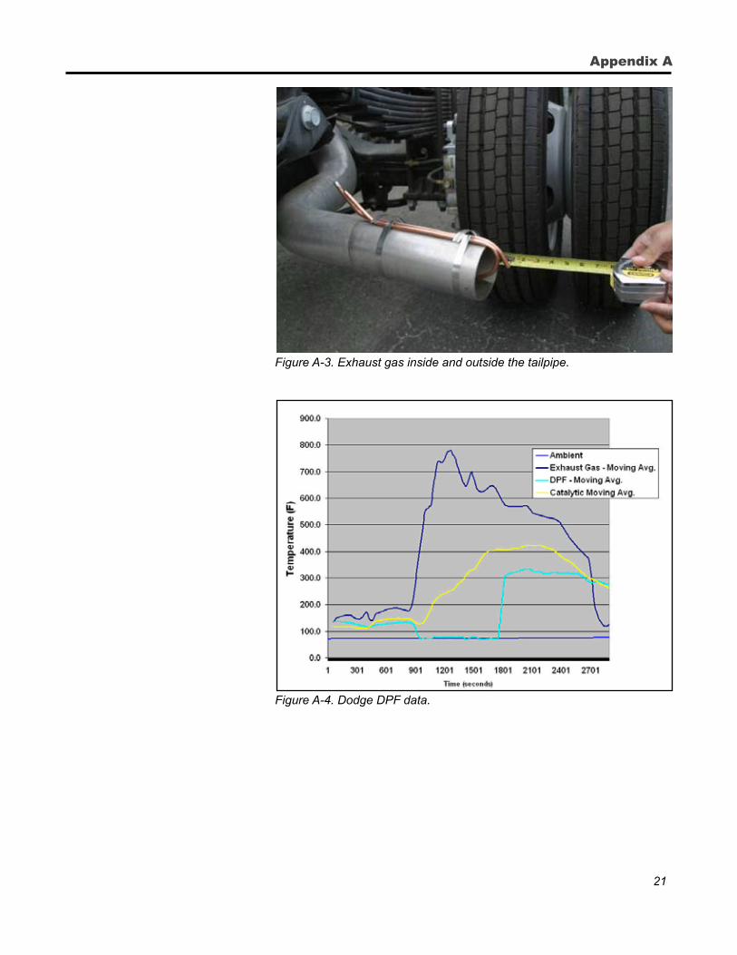
A malfunction of the thermocouple connection prevented the measurement of exhaust-gasses inside the tailpipe. The DPF surface-temperature data are incomplete; the initial readings were not recorded due to the malfunction of the thermocouple connection.
21
Figure A-3. Exhaust gas inside and outside the tailpipe.
Figure A-4. Dodge DPF data.
Appendix A
22
Diesel Exhaust Emission System Temperature Test
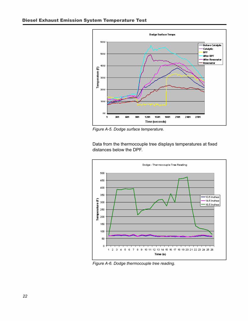
Figure A-5. Dodge surface temperature.
Data from the thermocouple tree displays temperatures at fixed distances below the DPF.
Figure A-6. Dodge thermocouple tree reading.
23
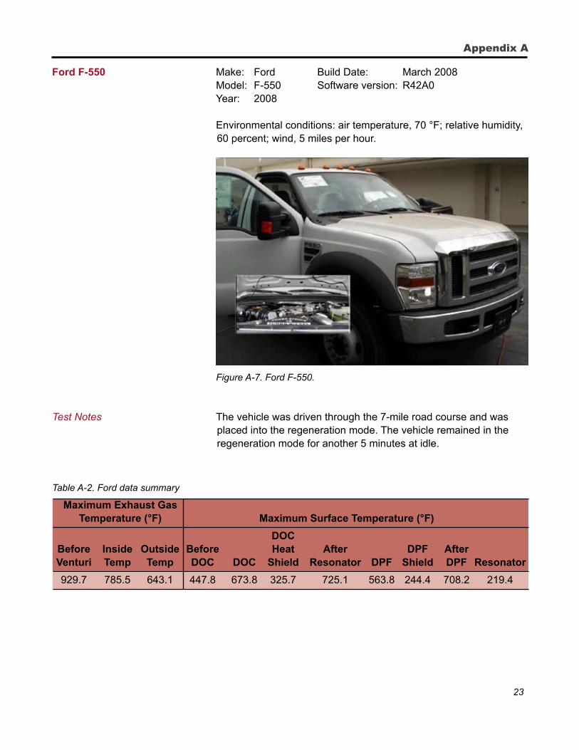
Ford F-550 Make: Ford Build Date: March 2008 Model: F-550 Software version: R42A0 Year: 2008 Environmental conditions: air temperature, 70 °F; relative humidity,
60 percent; wind, 5 miles per hour.
Figure A-7. Ford F-550.
Test Notes The vehicle was driven through the 7-mile road course and was placed into the regeneration mode. The vehicle remained in the regeneration mode for another 5 minutes at idle.
Table A-2. Ford data summary
Maximum Exhaust Gas Temperature (°F) Maximum Surface Temperature (°F)
DOC Before Inside Outside Before Heat After DPF After Venturi Temp Temp DOC DOC Shield Resonator DPF Shield DPF Resonator
929.7 785.5 643.1 447.8 673.8 325.7 725.1 563.8 244.4 708.2 219.4
Appendix A
24
Diesel Exhaust Emission System Temperature Test
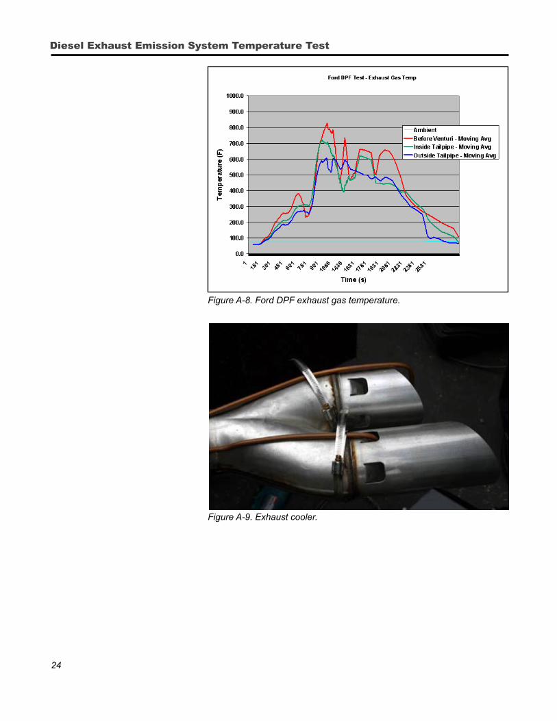
Figure A-8. Ford DPF exhaust gas temperature.
Figure A-9. Exhaust cooler.
25
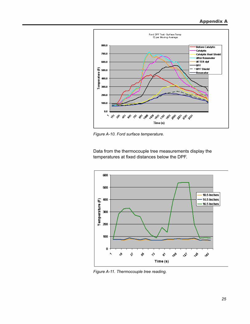
Figure A-10. Ford surface temperature.
Data from the thermocouple tree measurements display the temperatures at fixed distances below the DPF.
Figure A-11. Thermocouple tree reading.
Appendix A
26
Diesel Exhaust Emission System Temperature Test
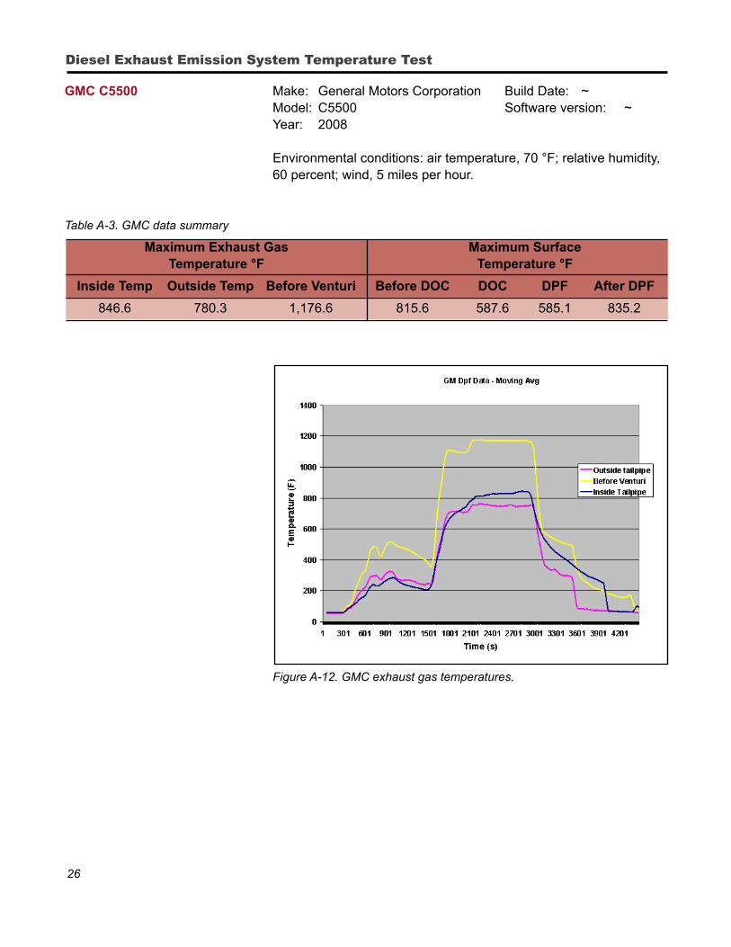
GMC C5500 Make: General Motors Corporation Build Date: ~ Model: C5500 Software version: ~ Year: 2008
Environmental conditions: air temperature, 70 °F; relative humidity, 60 percent; wind, 5 miles per hour.
Table A-3. GMC data summary
Maximum Exhaust Gas Maximum Surface Temperature °F Temperature °F
Inside Temp Outside Temp Before Venturi Before DOC DOC DPF After DPF
846.6 780.3 1,176.6 815.6 587.6 585.1 835.2
Figure A-12. GMC exhaust gas temperatures.
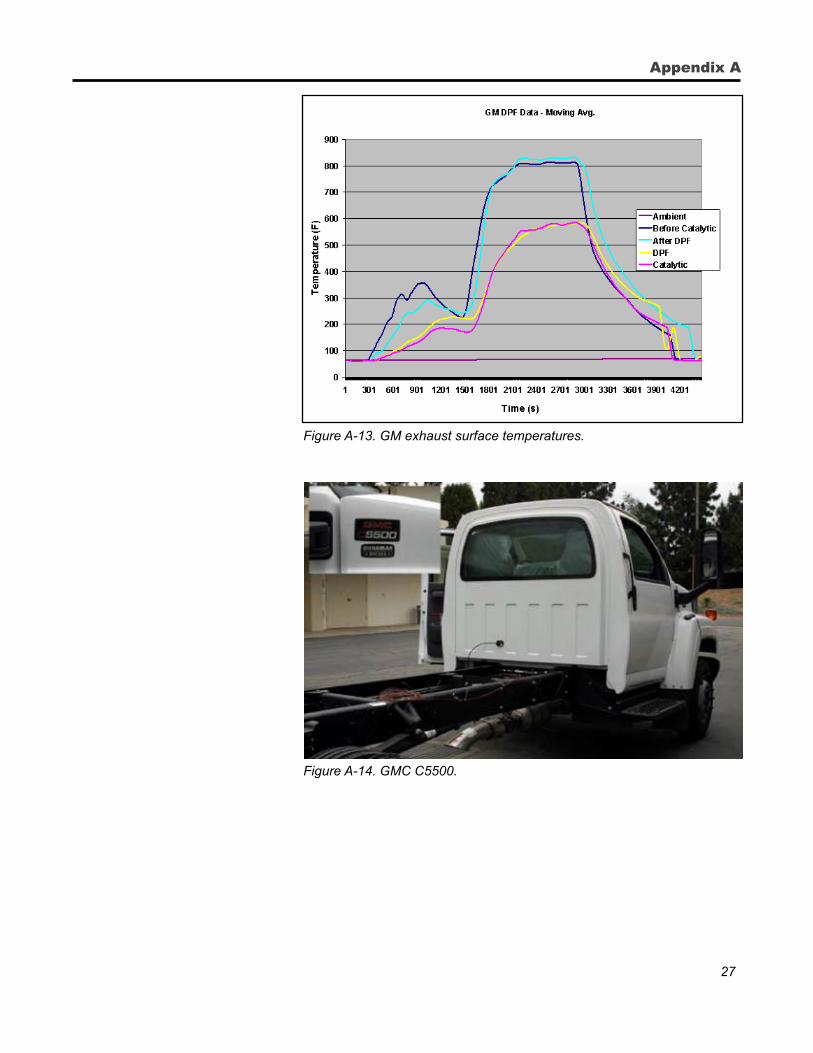
27
Figure A-13. GM exhaust surface temperatures.
Figure A-14. GMC C5500.
Appendix A
28
Diesel Exhaust Emission System Temperature Test
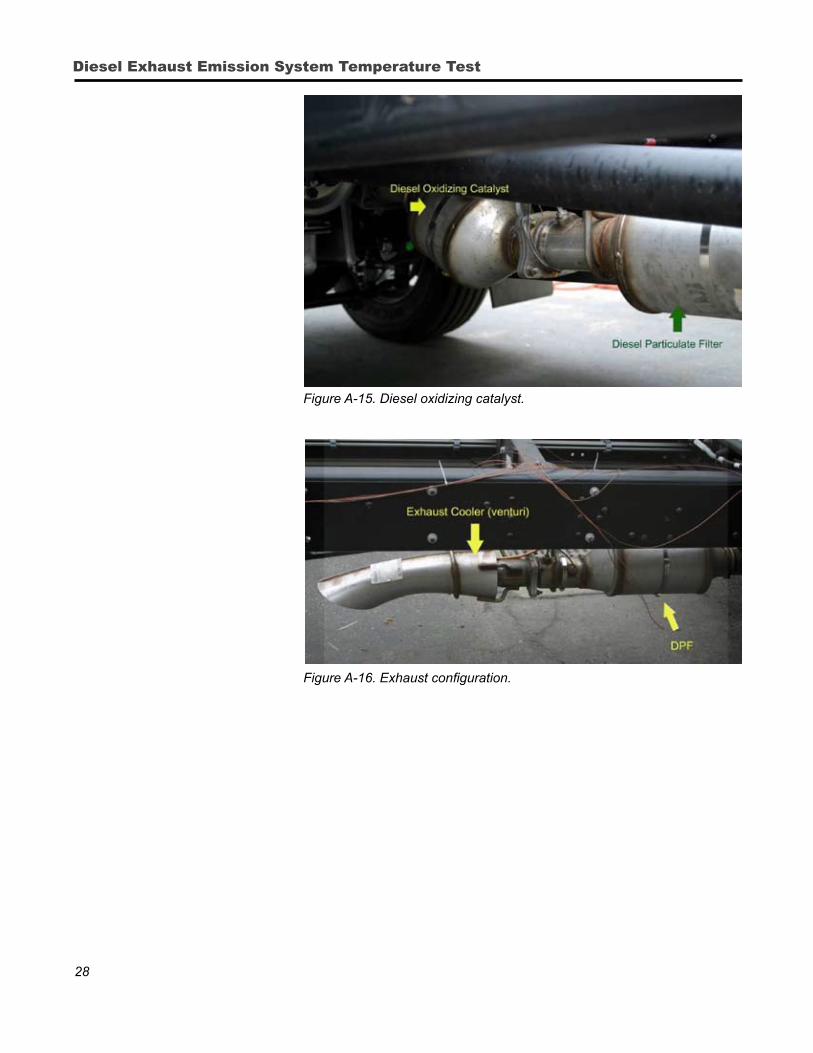
Figure A-15. Diesel oxidizing catalyst.
Figure A-16. Exhaust configuration.
29
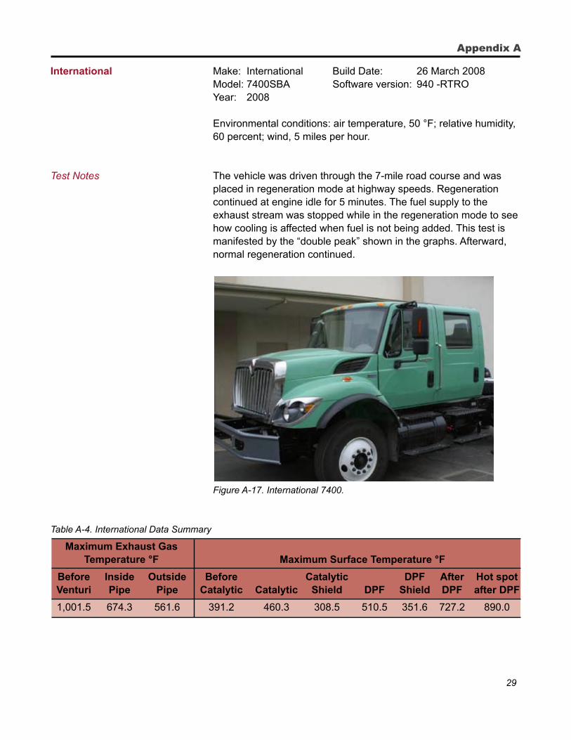
International Make: International Build Date: 26 March 2008 Model: 7400SBA Software version: 940 -RTRO Year: 2008 Environmental conditions: air temperature, 50 °F; relative humidity,
60 percent; wind, 5 miles per hour.
Test Notes The vehicle was driven through the 7-mile road course and was placed in regeneration mode at highway speeds. Regeneration continued at engine idle for 5 minutes. The fuel supply to the exhaust stream was stopped while in the regeneration mode to see how cooling is affected when fuel is not being added. This test is manifested by the “double peak” shown in the graphs. Afterward, normal regeneration continued.
Figure A-17. International 7400.
Table A-4. International Data Summary
Maximum Exhaust Gas Temperature °F Maximum Surface Temperature °F
Before Inside Outside Before Catalytic DPF After Hot spot Venturi Pipe Pipe Catalytic Catalytic Shield DPF Shield DPF after DPF
1,001.5 674.3 561.6 391.2 460.3 308.5 510.5 351.6 727.2 890.0
Appendix A
30
Diesel Exhaust Emission System Temperature Test
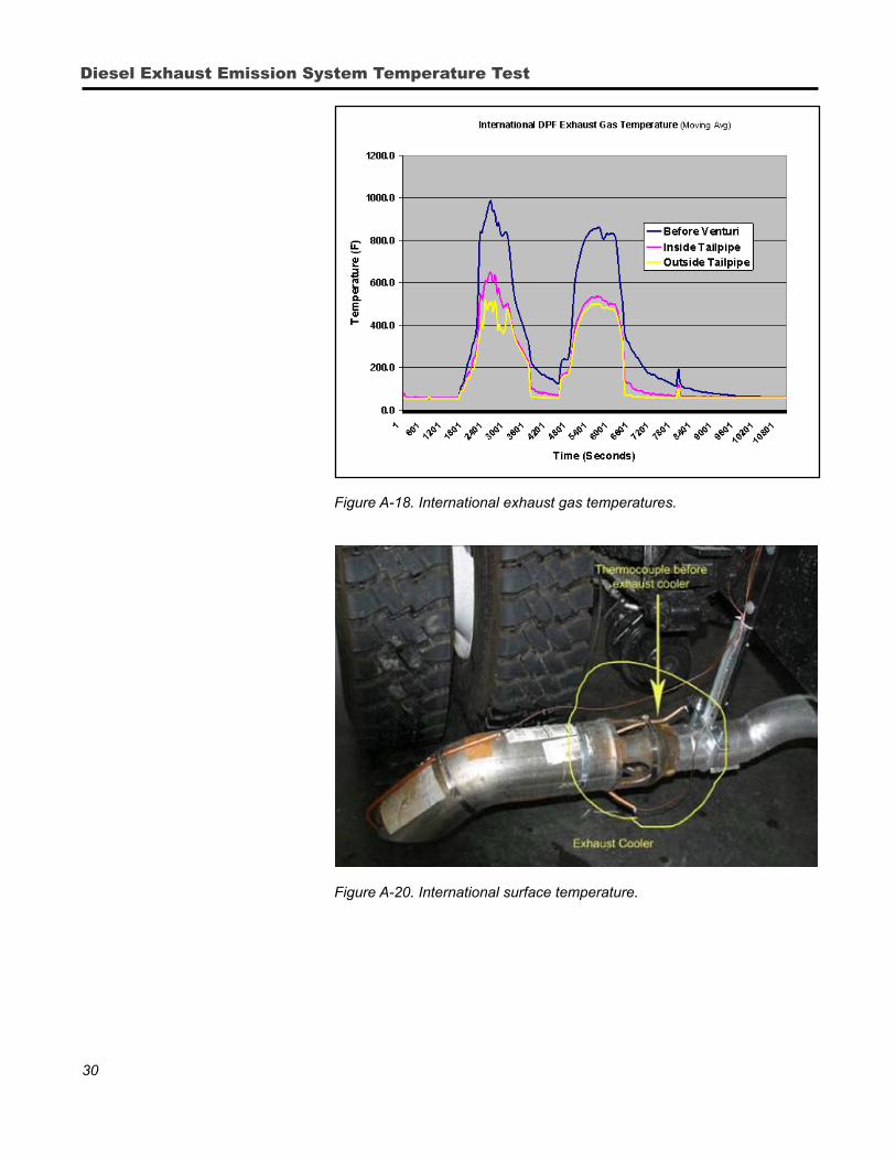
Figure A-18. International exhaust gas temperatures.
Figure A-19. Exhaust cooler.
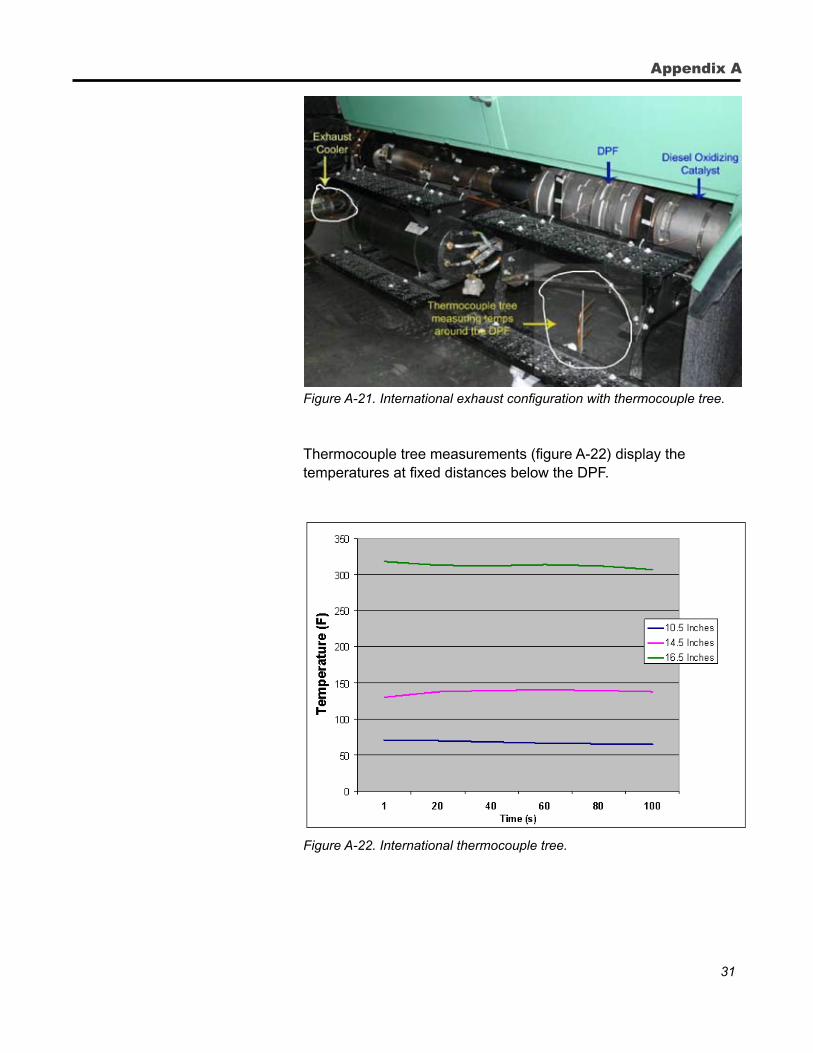
Figure A-20. International surface temperature.
31
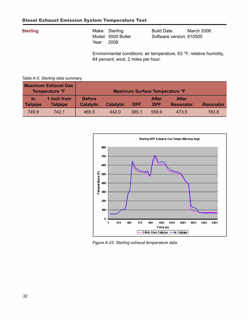
Figure A-21. International exhaust configuration with thermocouple tree.
Thermocouple tree measurements (figure A-22) display the temperatures at fixed distances below the DPF.
Figure A-22. International thermocouple tree.
Appendix A
32
Diesel Exhaust Emission System Temperature Test
Sterling Make: Sterling Build Date: March 2008 Model: 5500 Bullet Software version: 610500 Year: 2008
Environmental conditions: air temperature, 63 °F; relative humidity, 64 percent; wind, 2 miles per hour.
Table A-5. Sterling data summary
Maximum Exhaust Gas Temperature °F Maximum Surface Temperature °F
In 1 inch from Before After After Tailpipe Tailpipe Catalytic Catalytic DPF DPF Resonator Resonator
749.9 742.1 465.5 442.0 385.1 559.9 473.5 183.8
Figure A-23. Sterling exhaust temperature data.
33
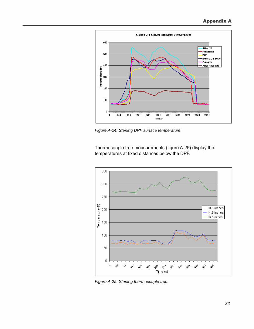
Figure A-24. Sterling DPF surface temperature.
Thermocouple tree measurements (figure A-25) display the
temperatures at fixed distances below the DPF.
Figure A-25. Sterling thermocouple tree.
Appendix A
Time (s)
34
Diesel Exhaust Emission System Temperature Test
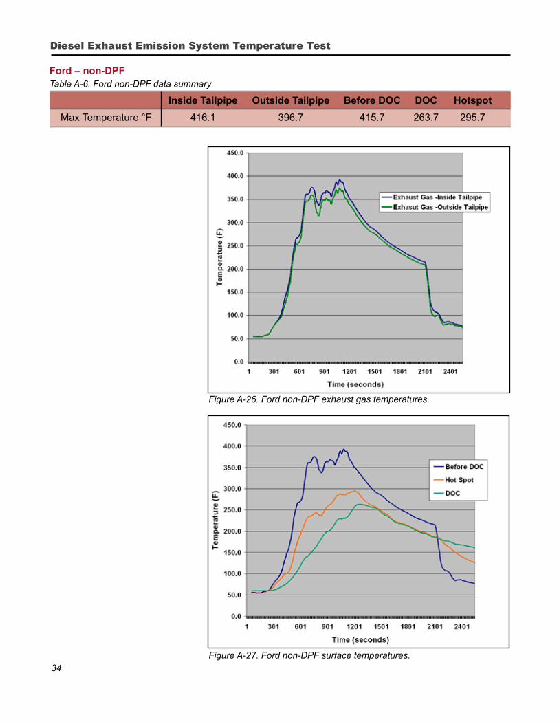
Ford – non-DPFTable A-6. Ford non-DPF data summary
Inside Tailpipe Outside Tailpipe Before DOC DOC Hotspot
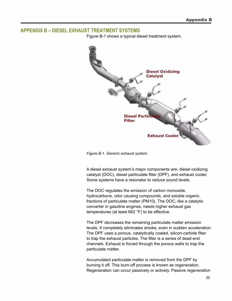
Max Temperature °F 416.1 396.7 415.7 263.7 295.7
Figure A-26. Ford non-DPF exhaust gas temperatures.
Figure A-27. Ford non-DPF surface temperatures.
35
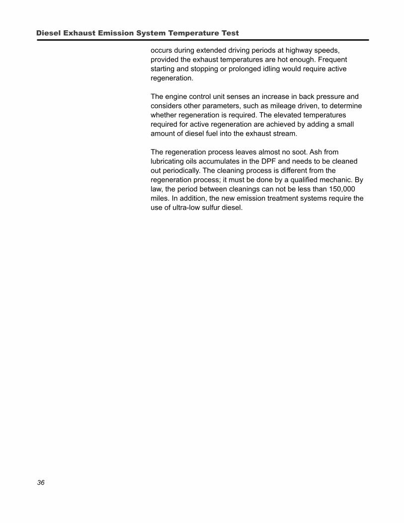
appendix b – diesel exhausT TreaTmenT sysTems Figure B-1 shows a typical diesel treatment system.
Figure B-1. Generic exhaust system.
A diesel exhaust system’s major components are: diesel oxidizing catalyst (DOC), diesel particulate filter (DPF), and exhaust cooler. Some systems have a resonator to reduce sound levels.
The DOC regulates the emission of carbon monoxide, hydrocarbons, odor causing compounds, and soluble organic fractions of particulate matter (PM10). The DOC, like a catalytic converter in gasoline engines, needs higher exhaust gas temperatures (at least 662 °F) to be effective.
The DPF decreases the remaining particulate matter emission
levels. It completely eliminates smoke, even in sudden acceleration. The DPF uses a porous, catalytically coated, silicon-carbide filter to trap the exhaust particles. The filter is a series of dead-end channels. Exhaust is forced through the porous walls to trap the particulate matter.
Accumulated particulate matter is removed from the DPF by burning it off. This burn-off process is known as regeneration. Regeneration can occur passively or actively. Passive regeneration
Appendix B
36
Diesel Exhaust Emission System Temperature Test
occurs during extended driving periods at highway speeds, provided the exhaust temperatures are hot enough. Frequent starting and stopping or prolonged idling would require active regeneration.
The engine control unit senses an increase in back pressure and considers other parameters, such as mileage driven, to determine whether regeneration is required. The elevated temperatures required for active regeneration are achieved by adding a small amount of diesel fuel into the exhaust stream.
The regeneration process leaves almost no soot. Ash from
lubricating oils accumulates in the DPF and needs to be cleaned out periodically. The cleaning process is different from the regeneration process; it must be done by a qualified mechanic. By law, the period between cleanings can not be less than 150,000 miles. In addition, the new emission treatment systems require the use of ultra-low sulfur diesel.
37
Tabl
e B
-1: A
ctiv
e R
egen
erat
ion
Fea
ture
Sum
mar
y
OE
M
Ind
icat
ion
th
at
Cri
teri
a fo
r Is
reg
ener
atio
n
Ave
rag
e In
dic
atio
n
Dri
ver
Can
C
an
reg
ener
atio
n is
re
gen
erat
ion
au
tom
atic
or
du
rati
on
fo
r th
at
init
iate
s re
gen
erat
ion
re
gen
erat
ion
re
qu
ired
to
beg
in
dri
ver
init
iate
d?
re
gen
erat
ion
re
gen
erat
ion
re
gen
erat
ion
b
e in
itia
ted
at
be
pre
ven
ted
is
co
mp
lete
b
y an
ytim
e o
r o
nly
b
y m
anu
al
wh
en e
ng
ine
o
verr
ide?
co
ntr
ol c
alls
fo
r
reg
ener
atio
n?
Dod
ge
Gen
eral
ly
Mov
ing
at o
r A
utom
atic
. 20
min
utes
no
ne
Driv
ing
O
nly
whe
n
No
no
ne. M
essa
ge
abov
e 15
mph
en
gine
con
trol
ce
nter
und
er
ca
lls fo
r
cert
ain
rege
nera
tion.
ci
rcum
stan
ces
Non
e .
For
d
none
N
one
Aut
omat
ic.
20 m
inut
es.
Non
e N
o co
ntro
l. O
nly
whe
n N
opr
e Ja
n 20
08
engi
ne c
ontr
ol
ca
lls fo
r
rege
nera
tion.
For
d as
of
Gen
eral
ly n
one.
M
ovin
g ab
ove
Aut
omat
ic.
Less
than
20
Gen
eral
ly n
one.
D
rivin
g.
Onl
y w
hen
No
Jan
2008
M
essa
ge c
ente
r
7 m
pha
min
utes
M
essa
ge c
ente
r
engi
ne c
ontr
ol
unde
r ce
rtai
n
unde
r ce
rtai
n
ca
lls fo
r
circ
umst
ance
s
.
circ
umst
ance
s
rege
nera
tion.
GM
cla
ss 3
D
ash
light
or
M
ovin
g at
or
Driv
er.
20 m
inut
es.
Das
h lig
ht
Driv
ing.
O
nly
whe
n N
o
mes
sage
cen
ter.
abov
e 30
mph
b
or
mes
sage
engi
ne c
ontr
ol
cent
er.
ca
lls fo
r.
rege
nera
tion
GM
cla
ss 4
85
Das
h lig
ht o
r
Par
king
bra
ke
Driv
er.
30 m
inut
es.
Das
h lig
ht
Pus
hing
but
ton.
O
nly
whe
n N
o
mes
sage
cen
ter.
set.
or m
essa
ge
en
gine
con
trol
ce
nter
.
calls
for
re
gene
ratio
n.
Ste
rling
O
nly
prob
lem
s M
ovin
g at
or
A
utom
atic
. 30
min
utes
. N
one.
D
rivin
g O
nly
whe
n N
o
note
d on
ab
ove
15 m
pha
engi
ne c
ontr
ol
mes
sage
cen
ter.
.
ca
lls fo
r
re
gene
ratio
n.
Inte
rnat
iona
l In
dica
tor
light
. M
ovin
g at
or
D
river
or
20 to
30
min
utes
In
dica
tor
light
P
ushi
ng b
utto
n O
nly
whe
n N
o
ab
ove
30 m
phb
auto
mat
ic.
ex
tingu
ishe
s.
or d
rivin
g.
engi
ne c
ontr
ol
or
par
king
bra
ke
calls
for
is s
et.
.
reg
ener
atio
n.
Not
es:
a –
Min
imum
spe
ed th
at m
ust b
e m
aint
aine
d fo
r th
e du
ratio
n of
reg
ener
atio
n.b
– D
rivin
g at
or
abov
e 30
mph
for
appr
oxim
atel
y 20
min
utes
will
als
o co
mpl
ete
rege
nera
tion.
Appendix B
38
Diesel Exhaust Emission System Temperature Test
liTeraTure CiTed
Babraukus, V. 2003. Ignition handbook: principles and application to fire safety engineering, fire investigation, risk management and forensic science. Fire Science, Issaquah, WA.
Baxter, Greg, 2004. Evaluating the fire ignition potential of all terrain vehicles in Alberta forests. Advantage Report Vol 5. No. 8, FERIC, Vancouver, B.C.
Fairbanks, J. P.; R. Bainer, Roy. 1934. Spark arrester for motorized equipment. Bulletin 577. University of California Agricultural Experiment Station, Berkeley, CA.
Harrison, Robin T., 1970. Danger of ignition of ground cover fuels by vehicle exhaust systems. ED&T Report 5100-14. San Dimas, CA: U.S. Department of Agriculture, Forest Service, Equipment Development Center.
Harrison, Robin T. 1977. Catalytic converter exhaust system temperature test. ED&T Report 5100-17. San Dimas, CA: U.S. Department of Agriculture, Forest Service, Equipment Development Center.
Kaminski, Guido C., 1974. Ignition time versus temperature for selected forest fuel. Project Record ED&T, San Dimas, CA: U.S. Department of Agriculture, Forest Service, Equipment Development Center.
SDTDC’s national publications are available on the Internet at:
http://www.fs.fed.us/eng/pubs/
Forest Service and U.S. Department of the Interior, Bureau of Land Management employees also can view videos, CDs, and SDTDC’s individual project pages on their internal computer network at: http://fsweb.sdtdc.wo.fs.fed.us/
For additional information on [name of project], contact Ralph Gonzales at SDTDC. Phone: 909–599–1267 ext 212. E-mail: [email protected]]

