u.s. department of commerce · maximum volumetric efficiency of the cylinder can be easily...
TRANSCRIPT

U.S. DEPARTMENT OF COMMERCENational Technical Information Service
NACA TM 501
EFFECT OF INTAKE PIPE ON THE VOLUMETRIC EFFICIENCY OF AN
INTERNAL COMBUSTION ENGINE
NATIONAL ADVISORY COMMITTEE FOR AERONAUTICS
WASHINGTON, DC
DEC 27
https://ntrs.nasa.gov/search.jsp?R=19930090861 2020-04-01T10:33:30+00:00Z


_::::


_ _ NATIONAL ADVISORY C0_C.[ITTEE FOR AERONAUTIC'S.
TECI_{ICAL i;_NORANDUM NO. 501
EFFECT OF INTAKE PIPE ON THE VOLU_TRIC EFFICIENCY
OF AN INTERNAL CONBUSTION ENGI!_. _
By _ntonio Capetti.
Stummary
The_riter discusses the phenomena of expansion and com-
pression which alternately tzke place in the cylinders of four-
stroke engines during the induction process at a high mean pis-
ton speed due to the inertia and _lasticity of the mixture in
the intake pipe.
All engine builders usually take care of this problem by
retarding the closing of the inlet valve. They know , however,
that the length of the intake pipe affects the maximtum power
of the engine through its effect on the carburetion.
In order to determine the effect on the charging of the
cylinder, the writer had previously worked out a method of the-
oretical research and had arrived at some interesting conclu-
sions on the existence of a most favorable condition for the
charging, which should take place in accordance with a certain
ratio of the pipe length to the piston stroke.
The present paper is in_ended to demonstrate theoretically
the existence of a most favorable pipe length got charging,
• "L'influenza della tubazione aspirante sul ren_imento volumet-
rico dei motori a combustione interna. " From Annalli della R.
Scuola d'Ingegneria di Padova, December, 1927, pp. !393-404.

N.A.C.A. Technical Nemor_ndum No. 501 2
which cam be adopted without disturbing the oa_buretion by using
an additienal pipe preceding the carburetor. The effect of
using the same pipe for several cylinders is also considered.
Reference is made to the experimental confirmation this
theory has received both from _merican experiments (by the
National Advisory Committee for Aeronautics) with a one-cylinder
engine and from the writer's experiments with a four.cylinder
engine, which are more fully described in the appendix.
The writer concludes with an analysis of the possible ef-
fects of special devices for inducing or damping the inertia,
such as "capacities" in series or in parallel.
I. Premises
The intake pipe cf an internal aombustion engine with a
four-stroke cycle is traversed by a pulsating current of air
or carbureted mixture.* It is obvious, therefore, that all the
phenomena of periodically varying currents, due to the inertia
and elasticity of the fluid, may be manifested.
These phenomena can be studied individually by considering
all the contributing causes, naz_ely, the ratio between the cross-
sectional areas of the pipe and cylinder; the obliquity of the
connecting _od; temperature and pressure differences between
the residues in the cylinder and the fresh charge; the friction-
*In the rest of this article I shall use the term "air," since
the very small quantities of carburetant or fuel present have
no appreciable effect on the phenomenon under consideration.

N.A.C.A. Technical Memorandum No. 501 3
al resistance of the vaziable valve opening, intake pipe and
carburetor.
These phenomena may also be considered theoretically by
comparison with other analogous phenomena, such as alternating
electric currents, notwithstanding some substantial differences
from our case, which involves only simple pulsating currents.
The inertia which the air opposes to the acceleration imparted
to it by the piston is not necessazily harmful to the charging
of the cylinder, though it reduces the motion of the air with
respect to the motion of the piston. At the first stroke,
therefore, the pressure in the pipe is reduced and the cylinder
is only partially charged (Fig. 1). This condition lasts until
the suction is not transmitted to the outside, i.e,, until the
front of the expansion wave has not reached the mouth of the
intake pipe. From this moment, however, a compression wave be-
gins to penetrate the intake pipe and push the air into the
cylinder, even after the piston has reached the lower dead cen-
ter and begun its return stroke.
It is obvious, therefore, that the initial retardation in
charging the cylinder may be offset by the succeeding inrush of
air. If the phase displacement reaches a specially favorable
value, a real superchazging should be effected by inertia, since
• This particular investigation has been already described in twoarticles: "Contributo allo studio del flusso nei eilindri dei
_motori veloci" (Ingegneria, 1923) and "Fenomeni dovuti alltiner -zia nella alimentazione dei motori aeronautici" (Annali della R.
Scuola di Ingegneria di Padova, 1927).

N.A.C.A. Technical Memorandum No. 501 4
the cylinder may remain charged with compressed air throughout
the whole or almost the whole of its length, in which case the
contained air will have a density and pressure somewhat greater
than the surrounding atmosphere.
II. Best Length of Intake Pipe
The best length o'f the intake pipe and consequently the
maximum volumetric efficiency of the cylinder can be easily
determined approximately by the following elementary reasoning.
The best dephasement is that at which the wave of maximum
compression reaches the cylinder at the instant the latter has
its maximum volume, i.e., when the piston is at its lower dead
center. The wave of maximum compression is produced, however,
by the refraction of the wave of maximum expansion or, in other
words, by the reaction to the maximum reduction of pressure,
which leaves the cyiinder at about the middl_ of the piston
stroke, because the piston is then moving at its m_ximum speed,
It is therefore necessary for the time required for the wave
to traverse the intake pipe twice (once in each direction) to
equal the time required for the piston to make about half a
stroke.
Then, if w indicates the mean velocity of propagation of
the waves (absolute velocity of sound) expressed in meters per
second, and if v represents the mean piston speed, likewise
in meters per second, the two time intervals to be equated are

h
N.A.C.A. Technical Memorandum No. 501 5
2_/w and c/2v. Hence the best ratio of the pipe length to
the piston stroke is
w
c 4v
We may give a different form to the ratio just found by intro-
ducing the number of revolutions per minute n, which is re-
lated to the mesaq piston speed v and to the stroke c by
the simple formula v = n c and we obtain30 '
= 7.5 -_ .*n
Asstu_ing w = 340 (at a temperature of 15°C), we obtain the
values given in Table I.
Table I.
n i000
2.55
1500
1.702000t 2aO0 I, SO00 I 35001.281 1.02 0.85 0.73
4000
0.64
4500
O. 57
5OOO
O. 51
These vslues are somewhat gres_ter than those obtained by careful
calculation and experimentation. They may be corrected by cb-
serving that the velocity of propagation of the waves is not
simply that of sound in a quiet mediura, it being necessary to
add or subtract the velocity of the air itself in the direction
of propagation. Letting u represent the velocity o_@_e@gir,
*It is interesting to note that this formula expresses,_tl_i_es-chance" between the motion of the pioton and the vibratid_In •
the pipe. The period of free vibration of _- tube open at _eend is 4_/w. The intske peried of the piston is 30/n. _qua-
tion (3) affirms that these two periods are equc_l. Thus the
phase displacement is of one-half stroke, or 90 ° , as in resonance
phenomena.

N.A.C.A. Technic_l Memorandum No. 501 G
the first of the two above-mentioned time intervals will then be
( I + I h- 2_ _ (1)w + u w - u/ w w _ -- u s
and equation (1) becomes
_ w (I - u--_'_.c 4u k v_]
The second line of Table II gives the values of the best pipe-
stroke ratio as calculated by equation (1), while the third
line gives the corresponding values according to equation (3).
For the velocity u, we can use twice the mean value,
since the waves of maximum expansion and compression are being
propagated while the velocity in the intake pipe is varying in
the vicinity of its maximtm_. We must, of course, adopt as the
mean value, the same v multiplied by the ratio of the cylin-
der section to the pipe section. In calculating Table II this
ratio was assumed to be 5.
Table II
O
0
i4 6 8 I0 12 14 16 18
31.2 14.2 10.6 8.5 7.I 6.1 5.3 4.7
20.9 13.8 I0.0 7.8 6.2 I 5.0 4.0 3.4

i
N.A.C.A. Technical l!emorandum No. 501 7
III. Results of More Complete Theoretical Analyses
We have already theoretically illustrated a special func-
tion of the intake pipe as an active intervening element in
charging a cylinder. The preceding considerations are incom-
plete, however, in various respects. As already mentioned,
their very nature does not permit the investigation of the ac-
cessory causes governing the phenomenon.
For this purpose, we need only to repeat the conclasions
reached in the above-mentioned investigations. Figure 2 shows
the theoretical curves of variation in the volumetric effici-."
ency and also the curves for the theoretically most favorable
angles of lag in the closing of the intake valves, as plotted
against the ratio of the pipe length to the pistonstroke. In_'. e
plotting these curves, no account was taken of the effect of
the residues in the dead spaces in the cylinders.
Another investigation demonstrated that the residues, in
so far as t._ey have a pressure higher than the atmospheric pres-
sure lower the volumetric efficiency considerably withou_
' _ _: ::ii__:_/letting the best lengths. On the contrary, tnese lengths_
shortened in so far as the temperature of the residues is higher
than that of'the atmosphere.

N.A.C.A. Technical Memorandum No. 501 8
IV. Resistance of Intake Pipes
Two further important cormments should be made regarding
the reasoning in Section II. The first one concerns a different
aspect of the functions of the intake pipe, namely, its f_iction-
al resistance to the passage of the air. From this viewpoint
the best form of pipe would be the shortest and largest possible.
The combined effect of the two functions, active and pas-
sive, is therefore a reduction in the inertia and in the best
length by an amount which increases with the velocity of the
air and therefore with the piston speed. The existence of a
best length is not eliminated, however, as has been demonstrated
by experimentation and calculation.
V. Effect of the Nt_mber of Cylinders
The second comment on the reasoning in Section II concerns
the adaptation of the same intake pipe to several cylinders of
the same engine. Thus far we have assumed that, when the in-
take valve opens, the air in the pipe has the s_me pressure as
the surrounding air. This hypothesis seems to be satisfactory
so long as the pipe supplies only one cylinder. In this case
the cylinder remains inactive for about three piston strokes.
During this time the w_ves left in the pipe at the end of the
suction stroke traverse it in both directions a great number of
times; 12 times, for example, if it concerns the best length
according to formula (I) or (2). The friction_l resistance al-

" r .°_ nN.A.C.A. Technic'al .,._e1_oranaum No. 501
k
. _k_̧
/: . _•i•'_'/•, ... ..
:%9
most completely damps these oscillations.
If two, three, four, or even six cylinders, as in several
modern small automobile engines, are supplied by the pipe or
by the larger part of it, the damping action does not have time
to take effect and the phenomenon of inertia is altered. Due
to the variety and complexity of the possible cases, it is<not
often possible to predict just how_things will happen. It may
be assumed, ho_vever, that the supercharging effect of the in-
ertia is diminished by the multiplicity of the suctions.
In fact, it is obvious that the best cylinder charging oc-
curs in the vicinity of the lower dead center of the piston on
the arrival of a wave of maximtum compression following a wave
of maximum reduction in pressure. If, for example, we have
four cylinders, the suction begins in one cylinder just as it
ceases in another, and therefore the wave of compression gener-
ated in the latter cylinder reta_'ds the pressure reduction in
the former cylinder with all its consequences.
By way of example, we will investigate in greater detail
this very co_mon case of a four-cylinder, four-stroke-cycle en-
gine for a considerable number of successive strokes by the an-
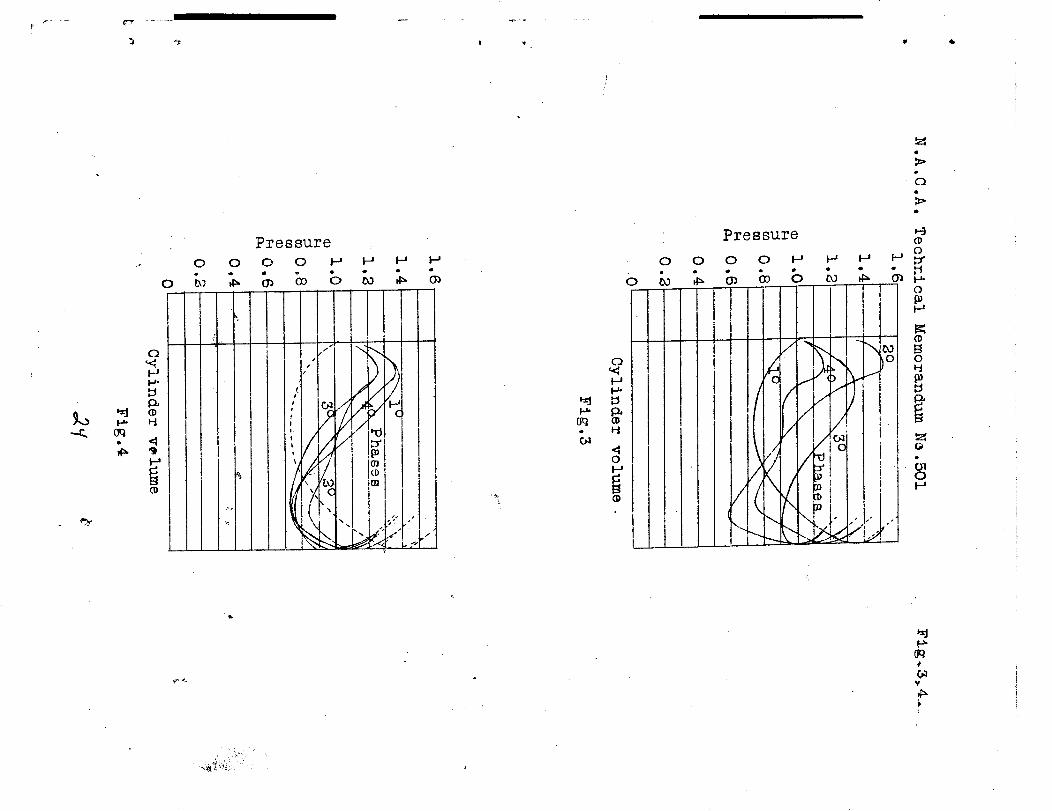
alytic graphic method already mentioned. Figure 5 shows the
pressure-voltume curves for the first four intake #hases o,f the
cylinders. Figure _ shows the corresponding curves for the
four succeeding phases. It is obvious that we are approaching
a pressure region quite different from that of the single cylin-

ST 0_l-eA %OZUT oq% _o _UTSOTO oq% uT _aI oq% aaq%oq_ _oqs souTIpguo$%uom-oAoq_ oq% 'a_nsso_d _uTX_A _ oT%_q_$P_ az_ sancho Oq%
io SUOT%_Od osoq% 'sTsoq%odA q Aq 'xeAo_oq _eouT8 -eA_no e_ns
-soad-uoT%onpu T qo_o io _oT%aod o_%_q_Tp_ oq% io puo 8q% q_noaq$
%Ireoos aO 0% %uO_u_% O/_ _ pT/_ _ "sZ_Z uT s8_I p_$%op 8qZ_
•_uTSreqo oIdT%Inm
oq% o% oI_UTs oq% moa_ _uTss_d u T o_umqo A_m q%_usI %soq oq%
%_q% oumss_ o% sn S_OIL'_ S_qZ "OS_O STq% U T OIdTa% _u_Oq poTa2
-od _q% _ouT_ua sq% _o %_q% _oa_ poTaod %uoao_ITp _ s_q aIq_%s
o_ooaq o% spuo% qoTqa uoT%_sInd _o 8%_a aq% %_q% _8Iq_% oq% _oal
ao%%oq IIT%S pu_ 'soxru_Tl oq% moa_ u_os AITS_O oq u_o %I
II'I i80"I
_-
_ • HH
1
i--_.
I--tt-4
o8_ = _T
! ICDC_ CDC_
I o _-' o _-a
I-_- I--'-(D (D
tO _-_
%I "I
o _-_
o
I-4
90"I 80"I
(DO C]Q
O _-_ O _-_}-_. _-_.(D (D
O_ tOH H
_I A 8 o:
c_ o9
o _-_ _.__-_. _¢_(9 CD
I-I ¢+
(D
ouT_uz a_puT, lAO--Tnoz n ;o AousToT;;.q OTa%Omu'LIO A TeoT%o.Tosqz
"III oIq_Z
"s_dTd
o_J_%uT a%_redos q%Tm ouT_uo a@puTlXO-OldT%IUm oq% aol (_u_.q%
om,es oq% o% s%u-aoum qoTq_) zo zopu_.IXO oI_uTs oq% zoj sonI_A
HuTpuodsea.Too eq% ureq% aoIlmms qonm _uT.sq sonItA osaq% II_ 's.Tsp
-uTIXO %uoaol_Tp oq% UT sozoa%s oXm%UT OAT.SSOOOnS 8q% iO Xouo
-_OT_iO oTa%om-aIOA oq% aol puno! Sanl_A oq% sa,_TZ III oIq_
,,•aall_mS
_oaH seTaoAooea eATsseoons eq% OlT_m 'ae%uoo p_op ae_Ol oq%
part, o% saAo_'_ uoT%oupoa o.rnssoad oq,T. "(9 "_T._ uT oAano qs_p) mop
OI ION .oN umpu_eaomo_ Teo!uqoa,T "V" O'V'_
!

N.A.C.A. Technical Memorandum No. 501
4
VI. Experimental Verification
ll
i'_
The theoretical predictions on the behavior of the intake
pipes have been satisfactorily confirmed by the few verifying
experiments thus far made. We will here refer to only two
series of tests, the first series, comprising the tests made by
the United States National Advisory Commit.tee for Aeronautics.*
The tests were made with a single-cylindel" (Liberty) engine
(of 5-inch bore and 7-inch stroke) which was operated by an
electric motor during the tests. The test conditions aiffered,
therefore, from those in ordinary practice, although they ap-
proximated the conditions in our first experiments, which _!elded
the curves of Figure 2.
The results of the _nerican tests are shown in Figure 5,
the abscissas being, as in Figure 2, the ratios of the length
of the intake pipe to the piston stroke, while the ordinates,
in the _o_e of other indications, are the ratios of the final
compression pressures, measured at various velocities, to the
compression pressure at the minimum velocity. They are, the_
fore, like the ordinates of Figure 2, representative values'_il _
the amount of the charge. [
Comparison of the two figures shows a sufficient agreement
of theory and practice for single-cylinder engines, despite the
fact that the lag in the closing of the intake valve remained
*Robertson _atthews _d Arthur W. Gardiner, "Increasing the Com-
pression Pressure in an Engine by Using a Long Intake Pipe."N.A.C.A. Technical Note No. 180, 1924.

N.A.C.A. Technical Memorandum No. 501 12
unaltered during the tests although, according to theory, this
lag should have varied both with the velocity and with the
length of the pipe.
The second series of tests was executed by the same parties
with a four-cylinder engine, provided with a co1_on intake pipe
throughout the whole length, excepting for the short passages
leading through the cylinder block to the different valves.
The details of these tests are given in a brief appendix to
this communication. _e will simply state here that the engine
was run continuously at full throttle ahd that careful control
was maintained of all accessory conditions, such as the tempera-
ture of the cooling water, the ignition timing, the proportions
of the carbureted mixture a_d the torque developed.
The test results, which the rather antiquated type of en-
gine did not permit carrying to very high piston speeds, are
shown in Figure 6, whose coordinates are the same as those of
Figure 2, and in Figure 7, whose abscissas are the mean piston
speeds.
Figure 6 shows that even in a four-cylinder engine with at
single intake pipe, there is a practical advantage in increasing
the length of the intake pipe up to a certain value. To be ex-
act, we found that by using a pipe length of 0.85, 1.1, 1.2, or
1.5 m (i.e., 6, 8, 8.6, or ll times the piston stroke) for corre-
sponding mean piston speeds of 7, 6, 5, and 4 m/s, we obtained
r@spective increases of 8.5, 10.5, 19.5, and 24% in the volumet-

N.A.C.A. Technical Nemorandum No. 501 13
tic efficiency. The phenomenon of supercharging by inertia was
thus verified in its essential features even in this case.
The principal divergencies from the theoretical prediction
for the single-cylinder engine (Fig. 2), apart from the easily
predictable reduction in the absolute valuers of the volumetric
efficiency, consist in the considerable reduction in thevb_est_
lengths and still more (Fig. 7) in the reduction in the Velio_city
of maximtun charging for each length. Especially wlth regard to ......_
the latter divergence, a considerable effect may be attributed
to the constanSy of the lag in the closing of the intake valves.
This was not verified, however, by the American experiments
(Fig. 5), where the lag was also kept constant.
We are therefore led to ce_]clude that the greater effect
is due to the number of cylinders supplied by the same pipe.
To this we may also attribute the peculiar shape of curve VII
in Figu_re .7, na_nely, the presence of two speeds of maximum
charging when the pipe is very long.
Figure 8 shows the ,,characteristic" curves (i.e., the
M.E.P. plotted a_ainst the R.P.N.) of an engine functioning• :i_]
with various additionalTengths of pioe for the purp6se of
showing how far the greater charging of the _9_]_ind_er _dde to
inertia in the long pipes_ is converted into:_grea%e r effective
brake horsepower. These curves have even greater practical
significance than those of Figure 7, in that they are not af-
fected by the subjective criteria of measurement and evaluation

N.A.C.A. Technical }_emorandum No. 501 14
which may be involved in the determination of the volumetric
efficiency (See the appendix). Of course care had to be exer-
cised during the tests to keep nearly constant the other condi-
tions affecting the mean effective pressure, namely, the compo-
sition of the mixture, the timing of the ignition, and the tem-
perature of the water for cooling the cylinders.
In its general appearance, Figure 8 resembles Figures 7 and
6. They all show that the engine power (curves II, III, IV and
V in comparison _ith curve I) is augmented by increasing the
length of the pipe up to a certain limit (curve VI corresponding
to 22 times the piston stroke). Even very long pipes have shown
advantages, however, for cr_uk-shaft speeds above 1300 R.P.E.
This fact, already obvious from the experimento_l results repre-
sented by curves VI and VII, shows their paradoxical character
with respect to the usual method of considering the effect of
intake pipes, because it is at high speeds that we would natnzal-
ly fear excessive resist_nces from very long pipes.
Lastly, we note that the maximum advantage found for the
mean effective pressure, and hence for the engine power, is
about ll%. It is, therefore, les_ than that found for the volu-
metric efficiency. This proves that the supercharging due _o
inertia is not gratuitous, but is obtained, as might be expected,
at the expense of the engine torque.
r
N.A.C.A. Technical Memorandum No. 501 15
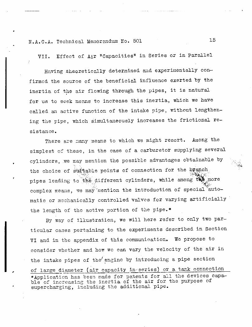
VII. Effect of Air "Capacities" in Series or in Parallel
Having _theoretically determined _d experimentally con-
firmed the source of the benefici_l influence exerted by the
inertia of the air flowing through the pipes, it is natural
for us to seek meo_s to increase this inertia, which we have
called an active function of the intake pipe, without lengthen-
ing the pipe, which Simultaneously increases the frictional re-
sistance.
There are many means to which we might resort. Among the
simplest of these, in the case of a carburetor supplying several
cylinders, we may mention the possible advantages obtainable by
the choice of S_._'_able points of connection for the b_ia_ich
pipes leading to _;h!_idifferent cylinders, while among t_ ore
complex mea_s, we maymention the introduction of special _auto-
matic or mechanically controlled valves for varying artificially
the length of the active portion of the pipe.*
By way of illustration, we will here refer to only two par-
ticular cases pertaining to the experiments described in Section
VI and in the appendix of this con_munication. We propose to
consider whether s_d how we can vary the velocity of the air in
4 _
the intake pipes of the _engine by introducing a pipe section
of large di_m_eter (air capacity in. series) or a tank connection
• •v .,i_̧ .
a_ the devices capa-*Application has been made for patents for _ble of increasing the inertia of the air for the purpose of
supercharging, including the additional pipe.

P
N.A.C.A. Technical Memorandum No. 501 16
(air capacity in parallel). If the capacity is inserted in the
pipe near the entrance, its effect on the voltumetric efficiency
of the engine is almost zero. In fact, when the waves of ex-
pansion or reduced pressure, in retraversing the pipe, reach
the greatly enlarged section of the c_Dacity, they are refracted
_nd form return waves of compression of little less strength
them those generated by ca_ external opening. Upon their amrival
at the cylinder, the beneficial compression waves are therefore
only slightly wc&kened during the first phase. In the second
phase, however, the waves whibh have advanced beyond the en-
lc_rged section and reentered the capacity are, in their turn,
refracted at the extern_l opening of the latter and form wo ves
of slight compression which facilitate the charging of the cyl-o
inder. Some advantage may result from these t_o phenomena if
the length of the inserted c_pacity is suitable.
Exact colculation confirms all this cmd gives, for the
case in which v = 12 m/s, /c = 6, and for _n air capacity
with a cross section ten times greater them that of the pipe,
a drop in the volumetric efficiency ranging from a loss of 3%
(for capacities over 14 tim_s the length of the piston stroke)
to a slight adva_ut_ge for capacities only 2-3 times the piston
stroke.
As to the velocity in front of, _nd particularly at
the external[ opening, it is not even groc_tly _±fected by the
presence of the i_serted co_pacity. In particular, there is no

N.A.C.A. Technical Memorandum No. 501 17
benefit of equalization of the velocities necessary, for example
for making important measurements by manometric methods.
This is evident if we remember that the velocity in the
connecting section between the capacity and the intake pipe is
given with close approximations by that of the adjacent pipe
divided by the ratio of their cross-sectional area. Since the
second velocity is onl}, slightly altered, the same may be said '_
of the first.
Moreover, this is demonstrated by the preceding calculations.
It is only necessary to compare the curves a snd b in Figure
9_ where the ordinates differ, but the general course, from
zero to zero, is similar.
Let us now pass to the case of a capacity "in parallel,"
also located n'ear the entrance. The effect on the charging of
the engine" is very small in this case also, because the wave
finds?a section so greatly enlarged at the point where the tank
is connected that it is refracted almost the same as at an ex-
ternal opening. However, the effects, althou_o_h small, is now of
the opposite sign to that of the preceding case. in fact, while
we first saw that, in a second period, the air tank was retrav-
ersed by compression waves (generated by the refraction of ex-
pansion waves at its open end), the tank is now_etzaw_rsed by
• For the exact valuation, it would be necessary to t_e intoaccount the ratio of the densities. This ratio,, however, hardlyreaches 1.05 for velocities of 100"m/s (328 ft./sec.) in thepipe at a temperature of 25°C.• _In order to make the figure clearer, the ordinates of the curveb are the velocities at the opening multiplied by lO, the ratioof the cross section of the air tank to that of the pipe.

N.A. C,A. Technical Memorandum No. 501 18
expansion waves generated by the reflection at its closed end
of similar waves coming from the cylinder. Lastly, the effect
of the capacity on the velocity of the air flow into the pipe is
very marked. It is only necessary to observe the curves c and
d in Figure 9 which, respectively, represent the calculations
we have made for the first intake stroke (or the first cylinder)
and for the third stroke (or the third cylinder).*
*The solutions of the cases of wave refraction given in our pre-vious papers are not sufficient for the analytical treatment of"capacity in parallel_" The method of reasoning employed inSection 2b of the paper "Contributo allo studio del flusso"(Contribution to the Study of Flow) is easily applicable, howev-er, to this case. It is only necessary to convert the first ofthe equations (6) into the form
u I p' q0+ u p _o = u" p",
in order to allow for the effect of the capacity in parallel andthen to add the three equations for the waves propagated in it:
k-I p - ; r - s = u; r + s - i
The solution of the system of nine equati0ns_ then proceeds in asimilar manner with the use of the auxiliary unknown quantities
= and 4o = P/P") and leads to the(two in this case, 4 P'/D"series of three equations solvable similarly to the equations(7)-
r _o 4o _ s" (_ *_'_+ _o 4o I"_) + r' _ *U" = 2
1 + _ _2+ _o _6 I"_
/ ,
r' (I + _o @oI"_:) _ r _o 4o"#I"_- s"_" _U ! = 2
1 + _ _+ _o 401"2
•
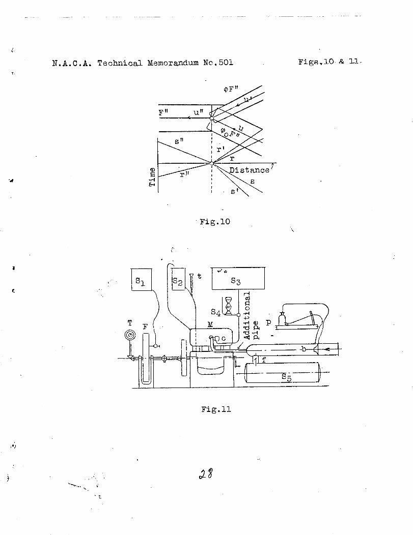
and likewise for u by changing _, 4, r ! and r into £0o, 40,
r and r' respectively, (Fig. i0). The values of 4 and _/o
are then found by trial, as explained in Section 2b of theabove-ment ioned paper.
_p

N.A.C.A. Technic_1 Memorandum No. 501 19
Appendix
Experimental Determination of the Volttmetric Efficiency
of an Engine Provided with Intake Pipes of Ve,_rious Lengths
The engine used in these experiments was a four-stroke-
cycle Fiat 53B with four cylinders of 8 cm (3.15 in. ) bore and
14 cm (5.51 in.) stroke; compression ratio 4.2; lateral vsXves
with about 60 ° la_ in the closing of the intake valve.
The intake passages through the cylinder block to the sin-_ _
gle carburetor have a mean length of about 40 cm (15.75 in.) _ _
between the intake valve of the cylinder and the mouth ef the :_:
carburetor. Consequently, this was the minimum length used in
the tests. In order to increase this, we added a pipe of 35 mm
(1.38 in.) diameter (hence, with a cross section equal to 1/S
of that of the cylinder) and of variable length up to about 4 m
(13 ft.)
The engine_was always operated at full throttle and braked
, with a R__uzi hy_raui_c dynamometer. The ignition advance _as
timed in each case 'S:_'(as to obtain the maximum torque.
We used a Zenith carburetor suitably modified to enable a
;_ _!,_ •
wide range of the mixture ratio. The fuel used was ordlnazy _<_
Shell benzine having a specific gravity of 0._2 at 30°0 (86°F)._,_i_._
The inducted air WaS measured by an orifice plate suitably
calibrated by the Montel method and connected with a sensitive
alcohol micromanometer (See Gramber, Technische Messungen, Edi-

N.A.C.A. Technical Memor_mdum No. 501 2O
tion VI, p. 193). In order for the orifice plc_te to operate
under favorable conditions, it w_js located at o_bout 2/3 of the
length of _ pipe ll5 mm (4.5 in.) in di_neter stud 1.5 m (near-
ly 6 ft.) long joined to the pipe of 35 mm (1.38 in.) diameter.
The previous theoretical investigations indicated that this
would not affect the inertia tests.
Figure ll shows the arrangement of the apparatus, compris-
ing the hydraulic brake F with its tank SI and the tachom-
eter T; the cooling-water tank $2; the engine _ M and thermom-
eter t; the fuel Zank 8s with the automatically refilled
container S_ for determining the hourly consumption; and the
micromanometer p with orifice plates before and behind the
air inlet or nozzle b, and carburetor c.
The formula for determining, from the pressure difference
P (in millimeters of water), the qu_ntity of air Q (in kilo-
grams per second), passing throughthe"opening, is
Q = _ FJ2 g 7 P,
where F represents the cross-sectional area (in m2) of the
restricted portion of the nozzle b, 7 the specific gravity of
the air, and a a coefficient-to be determined by calibration.
In order to obtain this coefficient, the _additional pipe
is connected directly to a centrifugs_l blower, %he quantity of
air flowing through the pipe being regulated by varying the
speed of the blower. All the tests gave the same coefficient
a = 1.004. However, while the _ir current generated by the

N.A.C.A. Technical _emorandum No. 501 21
blower can be kept perfectly constant, the current generated
by the engine is periodically very variable and may even be re-
versed for brief periods as shown by curve b in Figure 9.Q
The manometer connected with the ai_ inlet does not indi-
cate the mean value but that which, in the theory of alternate
" i.e. the squaremagnitudes, is called the "effeCtive value,
root of the mean square. If the air current varies, the coeffi-
cient _ must also involve the ratio between the mean va_ue and
the effective value. This ratio depends on the shape of_itlhe
curves of the air velocities. It would be 0.75 according to the
calculations used as the basis of Figures 3 and 4. It was de-
termined experimentally by resorting to a capacity of about 70
liters (2.47 cu. ft.) (85 of Fig. l-l), which could be put in
parallel, between the pipe containing the inlet nozzle b and
the additional pipe, by means of a valve f. The theoretical
researches, already mentioned in Section VII, gave assurance
that the parallel arrangement of the capacity would satisfacto-
rily serve the double purpose of _teadying the velocity behind
the nozzle b and in the additional pipe, and of rendering the_i L
flow through the measuring orifice almost perfectly uniform.
For the interpretation of the results of the _ts madeo$ •
without the capacity in parallel, it was finally decided to
adopt 0.6 as the value of the Ooefficient _i_;_
•8ee footnote next page. : ....

N.A.C.A. Technical Memorandum No. 501
• These tests were made before the nozzle b was calibrated.After this was done and the excessive valuation resulting fromthe application of the coefficient 1.004 was thus confirmed,we recognized the necessity of adding the air capacity in par-allel.
Translation byNational Advisory Committeefor Aeronautics.
?
4

II I i ill i
O,3
b :],
_+ Vol., ft_.
o oAnol_, of lag, efficiency
- i i\/ __ h .... ! _, !,< ..,_
® I--' n l /_ /_.0 ' \ '/ : I-'/
o --- / i . ii1 /1 • 1
/..ImO _ • " --• ' _I
o /- ....._ 1 - _i
"i" ?!i
.:. 0 _ 0 "o oo 8 0X1_" -...[ o. o
Ang_e . of lag. Vol.efficiency
... :. _-;,,'.-'
•. (..=.
1 "
I
/
o
o
o
t_
o
0
0q
I II I I I
O
Q
i_.
CD
(D
Pro88ure
0 0 0 I-'
I.
I-J
III
I °f
o
iJI-,.
p,
o
oo 0
Pressure
o o I-_ _-_
J
/
I
I
i.
f0o
o
o
9_
@
;1o
..!.-..
#
v

L
NoA.CoA. Technical Memorandum No.501
' I1.4
8._
l°O |
!I
Fig.5,6.
I,,,
II
i
0 2 4 6 8 lO
Ratio of pipe length t_ piston stroke
0
Fig.5
\ \
I: l:i : 1_ i _i ti i;, i
' 0 _ 8 12 16 20 24 28 3_
Ratio of pipe length to piston stroP@_(Fig..6
c__

I
f
N.A.C.A. Technical Memorandum No.501
._ o.8 , --.o
0.6
0.4
.f-I
q_o
o.M
4_o
i--4O
' "4- '/ Ii , VI i I! ! , .,
J i I I
' I I II I II I ll' i I
, , I Ii I I
},ie._+n iSton s#_ee,m shJ I /
I I I I I4, 5, 6t, 7#'
900 ilOO isoo i5oo 17ooR. P .It..
Fig.7Length of additional
0.2
(0700
Curve
i 0
Ii 0.35
III- 0.93
IV- I. 48
V 1.62
VI 2.60
VII- -3.92
6.0
5.5
c_
o5.0
h0
-,4.5
d
3.5
3 v 0
It'_.L "
iI
8OO
/f
t
iI
I i1200
R.P.M.
Fig.8
\I
!1600
Figs. T& 8
pipe.

r ....
N.A.C.A. Technical },,[emorandum No. 501 Fig.9
5F F
v = 12m/s
IOF
6_
:.7" .."
•(:. • : "i"$
L,
55O
_300-
.__50
o
_200
0
o 150
O
I000
50
I i
III
'" "J .L
-- jf \ ,
//_i_ i .i....-.-.....,.. , ..80 ° ' ZOO ° 120 ° l-iOo 160 °
O° 20o 40o 60o Cr ani_ angle.
_a,_,_V/ithout t_.nk.
b,._'ith tank in s3ries.
c; W;'ith ts.nk in porall_l.
_ _ I _d With tank in p_,r<.,l _I.
t
Fig.9
a9
-Ist cyl.
-2nd cyl.
180 °
' ..
•._,.y. , • ..
T.
N.A.C.A. T e chni c8_l Memorandum No.501
©
£-_
_tt -t.1ff /.jl__.
E311 _- i _'! "
:: .a,\ \
Figs.lO & l'L-
Fig.lO'\
/
Fig.ll

"0
Reproduced by NTISNational Technical Information Service
U.S. Department of Commerce
Springfield, VA 22161
This report was printed specifically for youorder from our collection of more than 1.5
million technical reports.
For economy and efficiency, NTIS does not maintain stock of its vastcollection of technical reports. Rather, most documents are printed foreach order. Your copy is the best possible reproduction available fromour master archive. If you have any questions concerning this document
or any order you placed with NTIS, please call our Customer ServicesDepartment at (703)487-4660.
Always think of NTIS when you want:• Access to the technical, scientific, and engineering results generated
by the ongoing multibillion dollar R&D program of the U.S. Government.• R&D results from Japan, West Germany, Great Britain, and some 20
other countries, most of it reported in English.
NTIS also operates two centers that can provide you with valuableinformation:• The Federal Computer Products Center - offers software anddatafiles produced by Federal agencies.• The Center for the Utilization of Federal Technology - gives youaccess to the best of Federal technologies and laboratory resources.
For more information about NTIS, send for our FREE NTIS Productsand Services Catalog which describes how you can access this U.S. and
foreign Government technology. Call (703)487-4650 or send thissheet to NTIS, U.S. Department of Commerce, Springfield, VA 22161.
Ask for catalog, PR-827.
Name
Address
Telephone
- Your Source to U.S. and Foreign Government
Research and Technology.