u.s. department of the interior u.s. geological survey · 2010-11-29 · u.s. department of the...
TRANSCRIPT
U.S. DEPARTMENT OF THE INTERIOR U.S. GEOLOGICAL SURVEY
CALIBRATION OF A LINEAR SPRING-SUPPORTED,VERTICAL-COMPONENT MOVING-COIL
SEISMOMETER BY MEANS OF DAMPING TESTAND/OR A CURRENT RELEASE TEST
BY J. P. EATON
OPEN-FILE REPORT 91-635
This report is preliminary and has not been reviewed for conformity withU.S. Geological Survey editorial standards.
Any use of trade names is for descriptive purposes only and does not implyEndorsement by the U.S.G.S.
Menlo Park, California 1992

CALIBRATION OF A LINEAR SPRING-SUPPORTED, VERTICAL-COMPONENT,
MOVING-COIL SEISMOMETER BY MEANS OF DAMPING TESTS
AND/OR A CURRENT RELEASE TEST
INTRODUCTION
The most commonly used seismometer in U. S. regional
networks today is the Mark Products L4-C vertical-component
moving-coil seismometer. This seismometer is convenient because
of its low natural frequency (1 hz), its high output level (1 volt/cm/sec across an appropriate load resistor), its small size (about 3" diameter and 7" height), and its rugged waterproof construction. Because its case is sealed, however, tests to
determine its operating parameters must be carried out by means
of electrical tests applied to the seismometer's output leads. From such tests and an a priori knowledge '(from the manufacturer) of the mass of the moving system, one can determine the free period, motor constant, and open circuit damping of the seismometer and can calculate values of two external resistors
(T=series and S=shunt) required to attain the desired damping and sensitivity.
In practice, two sets of tests are carried out: 1) before installation, the coil resistance, free period, open circuit damping, and motor constant are determined in the laboratory and the required values of the T and S resistors are calculated. This procedure detects seismometers whose parameters (usually
free period) are outside the range of acceptable values and
permits the seismometer to be set up with standard sensitivity
and damping when installed; 2)during normal operation in the field, an electronic step test and a current release test are applied periodically (once per day) to the seismic amplifier and the seismometer, respectively. The purpose of these tests is to
provide a basis for monitoring the free period, damping, and
motor constant remotely in order to detect seismometers whose
operating parameters drift outside the range of acceptable

values. Both sets are interpreted in terms of particular solutions of the differential equations of motion of the
seismometer. Accordingly, we shall derive the equation of motion in terms of the physical properties and operating partameters of the seismometer and shall obtain solutions corresponding to the
particular tests to be applied.
TRANSDUCER
First, we shall examine the moving coil (velocity) transducer and the interactions between currents and emf's in the
coil and forces on, and velocity of, the seismometer coil, which
is an integral part of the moving system.
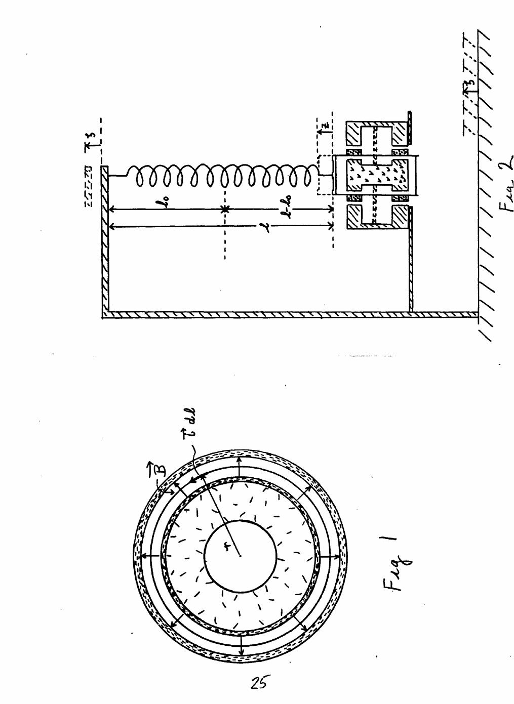
The L4-C, figure 1, employs a cylindrical magnet 36 mm high
with inside and outside diameters of 18 mm and 38 mm,
respectively, and a permeable cylindar 42 mm high with inside and*
outside diameters of 55 mm amd 58 mm, repectively, as the magnetic flux return path. Permeable 3-mm thick disc-shaped pole pieces 45 mm in diameter are mounted on the ends of the magnet and form 5 mm thick air gaps between the edges of the pole pieces
and the encircling flux path. Two circular coils, each with an inside diameter of about 46 mm, width of 12 mm, and thickness of
2 mm, are centered in the air gaps at the ends of the magnet and are mounted on thin (ca 0.5 mm) aluminum sleeves attached to the moving system. From the space occupied by the coil, and its resistance, it appears that the 5000-ohm L4-C coil consists of
about 8000 turms of #40 copper magnet wire.The strong magnetic induction in the air gaps is
perpendicular to the axis of the coils and is narrow (3-mm pole pieces) compared to the width of the coils (12 mm). The force on one turn of the coil winding due to the interaction of a current 7^ through the coil and an induction $ in the air gap can be written

3
where ^ and Ji are the radius and circumferenc of the coil and 1$ is the average induction in the region occupied by the coil.
For Y\ turns
r is parallel to the axis of the seismometer, i.e., along the vertical axis, and its sense depends on both the direction of
induction in the air gap and the direction of current in the coil. The two coils are connected in such a way that the current
is counterclockwise in one coil and clockwise in the other so that the forces (or emf's) produced by interaction of induction
and current (or velocity) in the coils at opposite ends of the magnet are additive.
In terms of the seismometer motor constant
3)the force on the moving system due to the current through its coil can be written
if)When the coil moves relative to the magnet, an emf is
generated in the coil
r =. -* " ~ i where "jTr is the rate of change of
flux through the coil,
From the construction of the transducer outlined above
0so;
Such an emf causes a current Lit) to flow in the coil andassociated circuit
, where P^ is the coil resistance
and 5 is tne resistance external to the seismometer. Thus,
Such a current through the coil, in turn, interacts with the
induction in the region occupied by the coil to produce a force
on the coil to oppose its motion
r\ ** ->
is an electrodynamic damping force that retards the coil's
motion.
The form of the foregoing equations in & and (3- ( i.e.,
having the constant of proportionality between F and the product t X> equal to 1 in equation 1) requires that we use the
absolute electromagnetic system of units. The relationships between these units and practical units are:
$ 9 10 amperes = 1 emu, 1 volt = /O emu, and 1 ohm = /O emu.
EQUATIONS OF MOTION
Consider a linear, spring-supported, vertical-component, moving-coil electromagnetic seismometer. like that indicated in
figure 2. Let 5 represent the position of the earth (and seismometer frame) with respect to a Newtonian framework $ ,
and let J represent the position of the seismometer moving system with respect to 2> . Let the parameters of the seismometer be specified as follows: M = mass of seismometer moving system, M = spring stiffness,
= zero length of spring (i.e., spring exerts no restoring force at length J^Q ) ,

-£ = working length of spring,
^ = acceleration due to gravity (980 cm/sec/sec), R = resistance of seismometer coil, L - inductance of seismometer coil, S = resistance external to seismometer coil, GT = seismometer motor constant (electrodynamic constant),
B- = emf generated across coil leads (open circuit) due to
relative motion of seismometer moving system and frame, Z = current flowing in seismometer coil.
We shall neglect the influence of coil inductance, L , on the seismometer current, £ , as is traditional. This omission should have little effect at the relatively low frequencies normally encountered in earthquakes (< 30 hz). The effect of
inductance during the current release test will be discussed below.
For a quiet earth, the forces acting on the seismometer moving system are:
a) Gravity: ~M^
,. _ . _L.ri P- P\-?l U /r/Mtf^^wJb) Spring: -f- (_( JL~Jrt>} *] M V <f
c) Damping:
open circuit A ̂.
electromagnetic G"J-
total damping \^^~
d) inertia: - A1 2:
For a moving earth, we must also add a virtual force to
account for the acceleration of the seismometer reference-f ./'
framework 3 with respect to the Newtonian framework 3

e) Virtual force: -f-M
Summing these forces we have
Simplifying and dividing by Al
Let - .-ri , where s 2.»j and
Note that -^-6-2.TT/o -Z7T/% , where 4? and 7?
are the natural frequency and free period of the seismometer,respectively.
iSubstituting the new coefficients of 2. and it :
Applying the Laplace transform to equation 9 and rearranging terms:
/o)
and
11} y
where -+ * » 0

In equation 11 the three terms on the right of the equal
sign correspond, respectively, to:
first - response of the seismometer to earth motion 3 (t)
second - response of the seismometer to an ititial
displacement ?(o)
third - response of the seismometer to an initialvelocity iM .
The specific earth motion we will consider is that in which the earth begins with simple harmonic motion beginning at "t~^- O :
t<0
For the case considered here ^(o) ~O , but "St?)
Equation 11 becomes:
.
where Tj and Tl_ are as defined above.Each term on the right hand side of equation 12 is of the
form = " 9 r where ** r and
are polynomials and the degree of &tf/ is greater than the degree
of -|0(T') . Furthermore, Gfr'f'Tycan be written in terms of its linear factors

8
For the case of most interest to us, $ < I , and all of the roots
are different. For the first term on the right the roots of
are + i <jj } ~ I UJ , T/ > and
For the remaining terms the roots are T/ and "Jo. .
Under these conditions the inverse of"
We shall next apply this rule to evaluate equation 12 to obtain equations for the seismometer displacement, "200 , for the
following cases:
1) harmonic response: (for ~>)(3r}'zP\4**<*>~t for ~t large)
2) release test:
3) tapping test:
HARMONIC RESPONSE
After inversion of equation 12 and manipulation of the results, the response of the seismometer to a long-sustained earth motion ^^f^ f\4^^ is:
This motion induces an emf S &« ̂ "' in the seismometer
coil and an emf ^^^ G" "i " across the external
resistor (figure 3).

RELEASE TEST
After inversion of equation 12 and manipulation of the
results, the response of the seismometer to an initial
displacement ~2-(0] is:
The emf generated by this motion across the external
resistor 5 is:
The first maximum insC"' occurs when ^flo-U
To use these equations in a practical calibration procedure we must be able to impart an initial offset *£.(o} to the mass and
to determine that offset with precision. Weight lift and current release tests for this purpose are discussed below.
TAPPING TEST
After inversion of equation 12 and manipulation of the
results, the response of the seismometer to an initial velocity
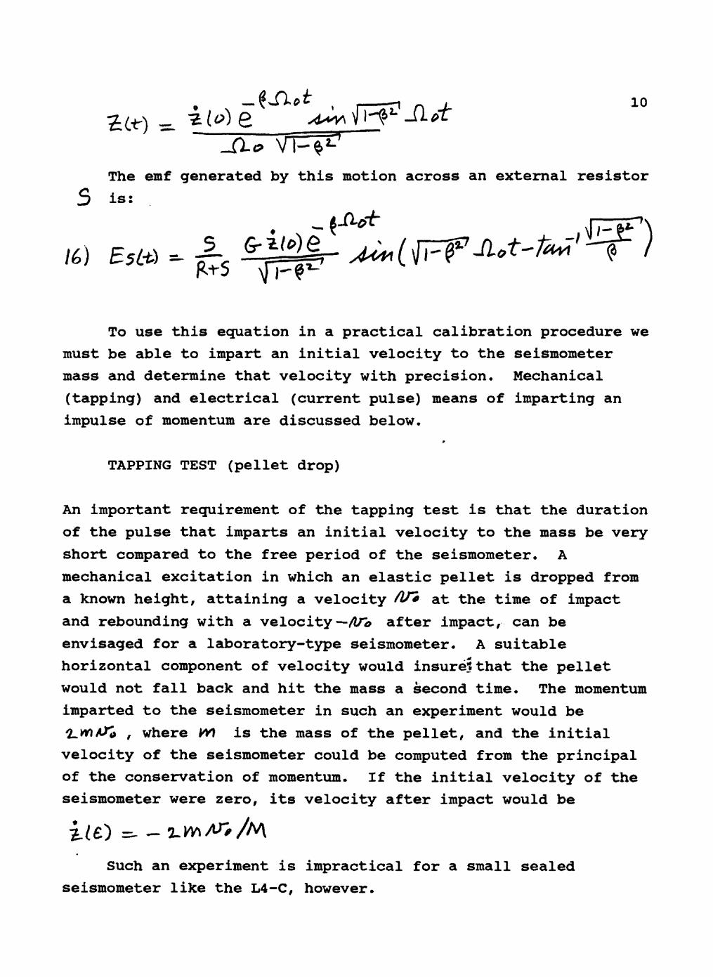
10
The emf generated by this motion across an external resistor
S is:
To use this equation in a practical calibration procedure we must be able to impart an initial velocity to the seismometer mass and determine that velocity with precision. Mechanical
(tapping) and electrical (current pulse) means of imparting an impulse of momentum are discussed below.
»
TAPPING TEST (pellet drop)
An important requirement of the tapping test is that the duration
of the pulse that imparts an initial velocity to the mass be very
short compared to the free period of the seismometer. A mechanical excitation in which an elastic pellet is dropped from
a known height, attaining a velocity /2/* at the time of impact
and rebounding with a velocity -/ln> after impact, can be envisaged for a laboratory-type seismometer. A suitable
horizontal component of velocity would insure? that the pellet
would not fall back and hit the mass a second time. The momentum imparted to the seismometer in such an experiment would be
2.MV* , where *VJ is the mass of the pellet, and the initial velocity of the seismometer could be computed from the principal of the conservation of momentum. If the initial velocity of the seismometer were zero, its velocity after impact would be
Such an experiment is impractical for a small sealed seismometer like the L4-C, however.

11
TAPPING TEST (current pulse)
A more practical means of imparting an initial velocity to the mass is to "fire" the charge of a small capacitor through the seismometer coil at "t-O . The current through the coil
exerts a force f (*"> & Gr t 6f) on the seismometer moving system
of mass M . The acceleration of the moving system due to
this force is
/ 7 ) "2; (£) ^~ (. ^'If appreciable current flows through the coil for a short interval of time, 0</£^£ / then the velocity of the mass at time £ can be calculated:
where the integral is the portion of the charge on the capacitor that traverses the coil.
The emf across an external resistor ^ in response to this test is:
RELEASE TEST (weight lift)
Returning to figure 2 and the definition of equilibrium the restoring force due to the stretched spring balances the gravitational pull on the mass:
If an additional mass W\ is placed on the mass, the spring stretches an additional amount

= W4
12
, but
jn/-( j. measured downward)
o} -z - W /\ SljT ( - measured upward)
Remove the weight and record the emf generated across the
external resistor
RELEASE TEST (current release)
Send a current H through the coil and wait until the
seismometer has come to rest. The current in the coil
interacting with the magnetic induction in the transducer
produces a force G-£ on tne mass which is balanced by a change
in spring force 2:/d)U resulting from the displacement of the mass
Cut off the current and record the emf generated across the external resistor
The first maximum (when -/Zfcvi V )~ <^ Sio^^- \J|^ftil //A ) is
*-*) 5
13
This treatment neglects the transient perturbation caused by
the pulse of current through the coil when the source is switched
off. Experiments show, for the L4-C, that the duration of this
current pulse is short (< 5 ms) and that the product
is quite small.
EFFECT OF COIL INDUCTANCE ON THE CURRENT RELEASE TEST
A simple experiment outlined by the circuit in figure 4 and illustrated by the graphs of voltage versus time in figure 5 was performed to evaluate the effect of coil inductance on the current release test. A reed relay P.R) controlled by a low-
frequency square wave from a signal generator alternately applied
and removed a voltage, supplied by a Hg-cell and 2000-ohm series
resistor, across a circuit consisting of the seismometer and series resistor T" in parallel with the shunt resistor 3 The current Cft") through the seismometer coil was measured with a high-quality oscilloscope by means of the voltage drop across
resistor "T . In the experiment, a current release test was
repeated about once every 10 seconds when the current through the
seismometer coil was interrupted by the opening of R R } . The
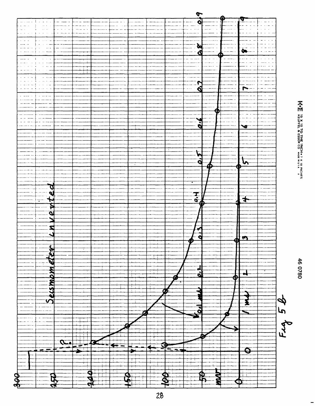
experiment was performed both with the seismometer upright (live release test) and inverted (circuit response test). Widely different horizontal trace speeds were required to reveal different aspects of the test.
Figure 5a, at 0.2 sec/inch, shows the release test preceded
by a sudden drop of (,&) to near zero at £i£0 . Figure 5a, at
2ms/inch, also shows the decay of current from LO (at"fr O ) to a minimum of about 2 microamps (5 mv/3000 ohms) at about 3 ms.
Figure 5b, at 0.1 ms/inch and 1.0 ms/inch, shows the initial
decay of current with the seismometer inverted, i.e., with the
release test suppressed. After a very^ short transient, during
which the current drops to about 1/4 Lo and then rebounds to

14
about 2/3 (.0 in the first 25 microseconds, the current declines
steadily to zero by about 4 ms. The initial sharp decline in current through T" may result from the capacitance of the coil:
when the external voltage source is cut off, the coil capacitance is "charged" and tends to drive a reverse current through the external circuit until it is discharged or overwhelmed by the larger effect of coil inductance, which tends to sustain a
foreward current through the coil.
For the case in which the seismometer is inverted, as shown
in figure 5b, theory predicts that the current in the circuit
will decline when the external voltage is removed according to:
LM xt. & ,' , RwhereThe total quantity of charge that flows through the coil
during the inductance-sustained decline of , current is:
/I J0
oo ""
t(>Q cj-t ^ i.t>~-*- ' and tnis charge passes through they
coil in only a few milliseconds. This charge produces an adventitious "tapping test" that accompanies the intended release test.
In the experiment illustrated in figures 4 and 5b,£' =. I3} ^00 ohms, (.» =_ O*IOQ VMO- f and the area under the
decay curve in figure 5b represents about O» 02.39 */£>"" amp-sec. Interpreting these values in terms of equation 25, we find
Finally, we can write down the system response to the
current release test by combining the current release test,
driven by a current L» , and the adventitious tapping test, driven by the current pulse due to inductance,

15
Comparing coefficients of the trigonometric factors for the experimental values shown above:
^ £ 6 7
Thus, the adventitious tapping test component of the overall response is only 0.15% as large as the proper release test component itself; so we shall neglect the effect of inductance altogether.
SIGN CONVENTIONS
Determining the proper sign to attach' to specific terms in many of the foregoing equations is a confusing task. To be complete we should know the direction of magnetization of the seismometer magnet and the sense of winding in the upper and lower coils. Failing that, we should know which lead goes positive with respect to the other for a sharp upward displace ment of the seismometer. To test the signs of various terms in the equations for consistency, however, it is sufficient to stipulate the direction of inductance and sense of current flow, for a positive voltage across the seismometer leads, in the upper coil: the direction of induction and current flow will be opposite in the lower coil.
Consider the diagram in figure 1 to represent a view from above of the upper L4-C coil and the indicated current direction (counterclockwise) to result from a positive voltage across the seismometer leads. The indicated sense of magnetic induction is radially outwards. With this diagram for reference, let us go through the current release test step-by-step.
1) Apply a positive voltage Vt> to the seismometer leads to establish a current L9 in the coil. The force on the coil is downward as indicated by the vector product (,(ffx$ of the

16
current in a coil element of length df and the induction 5 At equilibrium the coil is depressed an amount £(0), where T? is positive upward.
2) When the voltage is suddenly cut off (as in the experiment illustrated in figure 4), the coil inductance provides a positive emf that tends to sustain I in the counterclockwise direction. This diminishing current continues to interact with the induction to exert a downward force on the coil. The integral of the force due to this diminishing current over the brief interval that it is significant delivers a small downward pulse (of momentum) tothe coil and imparts a small downward increment of velocity to»it. Because (. begins to diminish as soon as the external voltage is cut off, in spite of inductance, the net force on the coil due to the upward directed restoring force of the spring and the downward directed force of the dying current is upward. Thus, the effect of coil inductance is to retard the return of the mass to its rest position by a very small amount. Taken by itself, however, the force due to the inductance-driven current is downward and produces a small downward "tap" on the coil. The downward-directed component of initial velocity from this tap interacts with the induction to produce a negative emf opposing the direction of 6
3) As the seismometer is pulled upward towards its rest position when the voltage is cut off, the movement of the coil through the induction in the gap produces an emf in the coil
given by <£6t) r fi-2&). The sense of this emf is given by the vector product «£.P/lrX# , where fir is the coil velocity and e6P is a small section of coil winding. Referring to figure 1, /ir is upward and ^ is outward; so d£ s-cfJ^' X K is in the
*direction of the initial current C» and is positive.The positive voltage so produced generates a positive current (in
tthe direction of L* ) which interacts with the inductance to produce a downward force that opposes the action of the spring that is pulling the mass back towards its rest position.
If the seismometer described above is subjected to a sharp

17
upward displacement, the coil moves downward relative to the magnet and a clockwise emf (and current) is induced in the coil.
The relationship between sense of ground motion and "polarity" of
the seismometer leads can be switched simply by exchanging leads.
In the release test, however, the polarity of the current
produced as the seismometer returns to zero remains the same as
that of the initial deflecting current.
DETERMINATION OF THE SEISMOMETER DAMPING AND MOTOR CONSTANT
FROM DAMPING TESTS
If we differentiate equation 23 for the current release test
with respect to time and recombine terms:
s'
offsfr)
<**r
From equations 23 and 28, the zeroes and extrema of Hs occur for
: zeroes
W~ /, *, 3, * : extrema
Successive zeroes as well as successive extrema follow one
another at intervals ~t = ~fe /2. «T @*^ , where To is the undamped free period of the seismometer. Thus,
lt> = N l-^2- / / where T is the damped period of the
seismometer.
The ratio of successive extrema of E$ i^) is:

Let &
Then
18ft
, where X i-s the logarithmic decrement.
Recall, from the definition of A , that
ft=0»-»-(^ ^_L-_ /^^^ "\Y v £/M-fl-« I & *$ / » whe^e
Let
Then
33)
Note that the expressions for $ and o~ contain no term in
deflecting current or voltage. In fact, it does not matter how
the seismometer is set in motion so long as its motion is free
after some arbitrary time preceding the first extremum used in
determining (2
Note, also, that the equation for (3" contains the seismometer mass A1 . We have no practical means for measuring /V\ without dismantling the seismometer. For this reason the
manufacturer is required to supply a measured value of /A for each seismometer.
The free period can be determined by measuring the damped period (preferably for the open circuit test) and correcting it for damping according to equation 29. Because the open circuit
damping of the L4-C is relatively high (ca 0.3), only a few
extrema of the release test can be measured. Also, it is simple

19
to determine To by a separate experiment. One such method puts
the seismometer in series with a load resistor and a sine-wave
generator. The voltage across the resistor is displayed on the
vertical axis of an oscilloscope and the voltage across the
seismometer is displayed on the horizontal axis. The frequency of the sine wave is then varied until the voltage across the seismometer and the current through it (measured as voltage
across the series resistor) are 90* out of phase, which occurs when the driving frequency matches the natural frequency of the seismometer. This experiment is facilitated if a generator with adjustable phase reference is available.
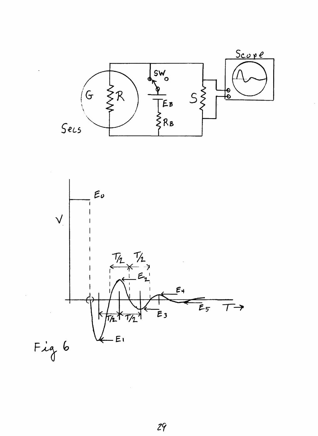
In the determination of <y by the damping test it is desirable to repeat the experiment with several different values
of the shunt in order to get some idea of the precision of the method. Figure 6 shows a circuit that can be used for the damping test, as well as a diagram of the expected response indicating the measurements to be made. Shunt values should
range from cO , open circuit, through values from about 10 to 2 times the seismometer resistance.
The accompanying table summarizes damping tests on one L4-C seismometer.
^ = 5580 ohms
M = 980.0 gramsTO = 1.039 seconds
^j \- -"-"««r^
O"20155.
14999.
13280.
0.271
0.507
0.561
0.592
0.000
0.236
0.290
0.321
25695.
20579.
18860.
i
6064.
5968.
6054.
+0.6-1.0
+0.4
average = 6029.
From equation 33 and the experimental values determined

20
above :
=.2_, 671,
Q ^ 1To attain 0.80 critical damping of the seismometer we can
calculate the required seismometer load (total external
resistance) 'T) from equation 32:
=5817 ohms for the case above.With the values of Gr and I? determined above, we can turn
to appendix 1 to calculate the series and shunt resistors, T and
S, respectively, that will provide the required 0.80 critical damping and will adjust the seismometer output to the standard
1.0 v/ cm/ sec across a 10,000 ohm amplifier- input resistance*
When A1; -/* *) "X) and fi are known, G" can be determined
from the first maximum of the current release test, equation 24,
to corroborate the value determined from the damping tests.
ACKNOWLEDGEMENT
John Vanschaack facilitated this work through his help in
setting up the experiment to evaluate the effect of coil
inductance on the current release test and through discussions of
the characteristics of the L4-C seismometer and the electronics
by which it is recorded.
FIGURE CAPTIONS
Figure 1 Schematic drawing, from above, of the upper half of the
L4-C transducer.
Figure 2 Schematic drawing of a spring-supported, vertical- component seismometer showing spring length

21
seismometer moving system coordinates earth coordinates
and
Figure 3 Diagram of a moving coil seismometer circuit
under working conditions.
Figure 4 Diagram of the experimental circuit employedto evaluate the effect of coil inductance on the current release test.
Figure 5 Experimental results from the circuit shown in
figure 4: a) current release test shown with
slow time axis; b) circuit response (current
release test with the seismometer inverted) with a fast time axis.
Figure 6 Test circuit and typical seismometer response
for a damping test driven by a current release.
22
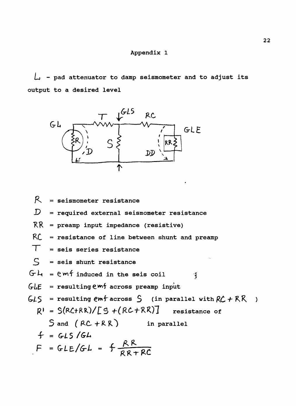
Appendix 1
LJ - pad attenuator to damp seismometer and to adjust its
output to a desired level
GrLE
D
KRC
= seismometer resistance
= required external seismometer resistance
= preamp input impedance (resistive)
= resistance of line between shunt and preamp
= seis series resistance
= seis shunt resistance
= £wf induced in the seis coil -1
= resulting S^i across preamp input
= resulting gvnjr across $ (*n parallel wi
= S(R£"f"RlO/t.. 5? -f-( R£<^XKj J resistance of
S and ( RC^ + R. ^ in parallel
= GLS /GL*
F = G-LE./6-t - f
R 1

23
For given values of /^ , ^R, , J^C. , and£-Zj we wish to
select T" and 3 to provide the correct external seismometer
damping resistance, ^ , and to adjust the seismometer output
(sensed across RR. ) to a prescribed value £-Zj£ Our basic
relationships are:
> I
The second equation reduces to
p =«Solving for ^
Solving for 7"~ from the first equation
(2) T = p-
i. if
, where
S =

24
ii. if :D/L
O
To calculate 3 and ~ (for given R. , /i.R^ , fi, £ ,»
and G-L ) to attain a desired value of 6-/-£. :
(a) Calculate P ^
(b) Test F for admissability
if
if V(c) Calculate $ from (1)
(d) Calculate T"~ from (2)
(e) Calculate
\\\
\\
X
\\1\3 \>i
issra 2s
Ha vv"vvn*
hi
i U'H
N

F-3
sSees
5tis

10 X
10 TO
TH
E IN
CH
7 x 10 IN
CH
ES
KE
UF
FE
L »
ES
SE
R C
O
u.n
r m II s «
I4
6 0
78
0
K-
10 X
10 T
O T
HE
IN
CH
. 7 x
10 INC
HE
SK
EU
FF
EL
* E
SS
ER
CO
««D
E IK
U s « I
46 07
80