us doe casl program fuel performance modeling for … · us doe casl program fuel performance...
TRANSCRIPT

Robert Montgomery1, C.R. Stanek2
W. Liu3, B. Kendrick2
Presented at the
IAEA Technical Meeting “Modelling of Water-Cooled Fuel Including
Design-Basis and Severe Accidents”
28 October – 1 November 2013, Chengdu, China
US DOE CASL Program Fuel Performance Modeling for Steady State
and Transient Analysis of LWR Fuel
This work was supported by the U.S. Department of Energy, Office of Nuclear Energy.
3
1
2

Presentation Overview
Overview of CASL Program Fuel Modeling Efforts
Accident fuel behavior and importance of modeling/modeling needs
Peregrine and MAMBA development activities
Lower length modeling/methods development
Data Needs for Fuel Modeling Support
Lower length modeling/methods development
Transient modeling activities in CASL
Summary

“Energy Innovation Hub” Consortium for Advanced Simulation of LWRs
CASL will apply existing modeling and simulation (M&S) capabilities and
develop advanced capabilities to create a usable environment for
predictive simulation of light water reactors.
CASL partners are from national labs, universities and industry.
CASL consists of 6 technical
“focus areas”:
• Materials Performance
• Thermal Hydraulics
• Neutronics
• Validation/Uncertainty
• Model Applications
• Virtual Reactor development

Longer-term priorities (years 6–10) Near-term priorities (years 1–5)
CASL vision: Develop & apply a “Virtual Reactor” to assess fuel design, operation and safety
Deliver improved predictive simulation of PWR core, internals, and vessel
Couple VR to evolving out-of-vessel simulation capability
Maintain applicability to other NPP types
Execute work in 5 technical focus areas to:
Equip the VR with necessary physical models and multiphysics integrators
Build the VR with a comprehensive, usable, and extensible software system
Validate and assess the VR models with self-consistent quantified uncertainties
Expand activities to include structures, systems, and components beyond the reactor vessel
Established a focused effort on BWRs and SMRs
Continue focus on delivering a useful VR to:
Reactor designers
NPP operators
Nuclear regulators
New generation of nuclear energy professionals
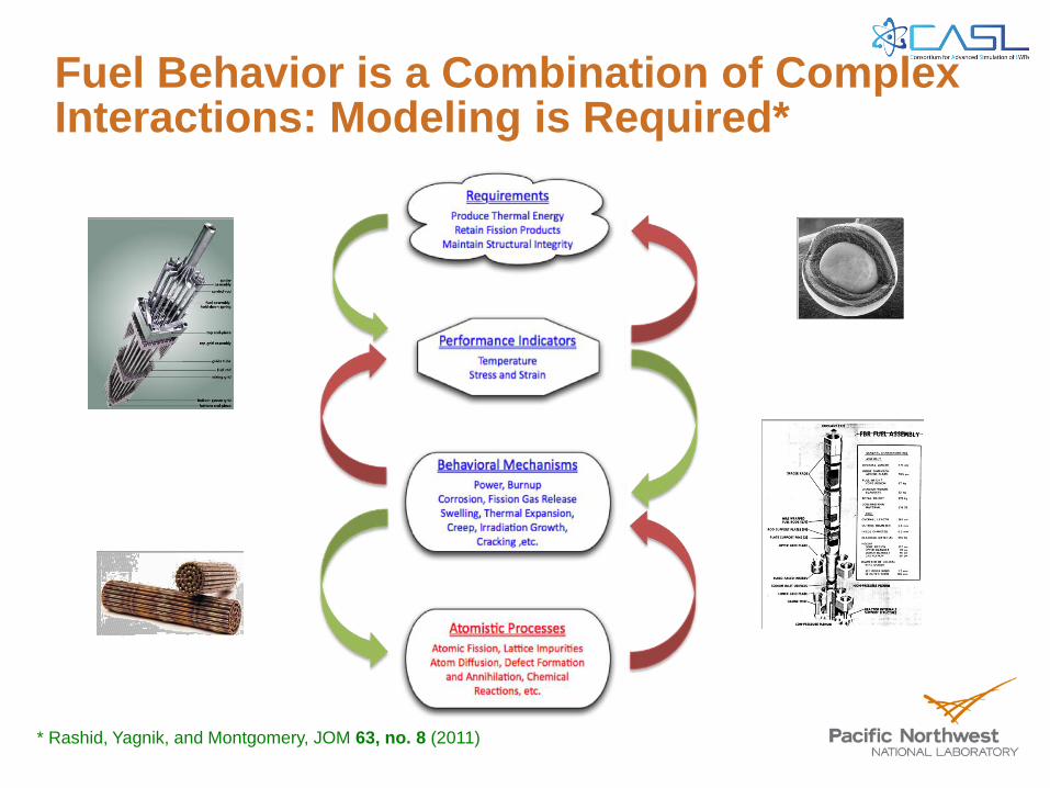
Fuel Behavior is a Combination of Complex Interactions: Modeling is Required*
! "#$%&' () "%$(8@%'@3%K (Z%*(<<<( Z%*(<[ (
89: ;<! =(4 "$560123#2(4 %-0. +(C"*%(Q;EA(FGHG( \ (
! "#$%&' () "%$(8@%'@3%K (Z%*(<<<( Z%*(<[ (
8 9: ;<! =(4 "$560123#2(4 %-0. +(C"*%(Q;EA(FGHG( \ (
! "#$%&' () "%$(8@%'@3%K (Z%*(<<<( Z%*(<[ (
8 9: ;<! =(4 "$560123#2(4 %-0. +(C"*%(Q;EA(FGHG( \ (
! "#$%&' () "%$(8@%'@3%K (Z%*(<<<( Z%*(<[ (
89: ;<! =(4 "$560123#2(4 %-0. +(C"*%(Q;EA(FGHG( \ (
* Rashid, Yagnik, and Montgomery, JOM 63, no. 8 (2011)

Outcomes and Impact Approach
Multi-Physics/Scale Material Modeling Enabling Improved Fuel Performance through Predictive Simulation
• Provide physics-based materials models of fuel/clad/internals property evolution to enable predictive modeling of CRUD, GTRF and PCI within 3D, multi-physics, virtual reactor simulator
• Improved physics and chemistry insight delivered via constitutive relations
• MPO is comprised of a diverse group of computational materials scientists with a wide range of capabilities
• Predictive models of fuel failure, that quantitatively define operating margins & lifetime limits
• Validated predictions of fuel failure conditions
• Power uprates & increased fuel utilization
Challenging, multiscale processes
impact nuclear fuel performance

Fuel Performance Modeling in CASL for PCI and CRUD
A series of microscale activities provide mechanistic/physical
insight into complex degradation phenomena
CRUD
MAMBA (MPO Advanced Model
for Boron Analysis)
PCI
Peregrine (Fuel Performance)

Copyright by ASTM Int'l (all rights reserved); Fri Aug 14 20:28:09 EDT 2009Downloaded/printed byDion Sunderland (ANATECH Corp) pursuant to License Agreement. No further reproductions authorized.
PCI in Fuel Behavior Modeling: Why it is important?
PCI failure potential limits reactor performance associated with power uprates, higher burnup, fuel rod manufacturing quality and operating flexibility during power changes
Requires new 3D multi-physics simulation capability to reduce uncertainties in assessing PCI failure conditions during normal operation and in the presence of anomalies`
Material
Properties &
Characteristics
Reactor
Neutronics
Thermal
Hydraulics
PCI
Fuel Behavior
Analysis and Modeling
Methodology
PCI is controlled
by local effects
PCI is possible in many
rods and assemblies
PCI has system wide
influence

CRUD Buildup and Boron Deposition Is Important for Plant Operation
Large Mass of Material
In Reactor System for
Corrosion
CRUD deposition is
wide spread with non-
uniform effects
Reaction kinetics occur
at lower microscale

Transient Fuel Behavior: Reactivity Insertion Accidents (RIA)*
Pellet Thermal Expansion
- Pellet-Cladding Contact
- PCMI Loading
Cladding Failure by Hydrogen-Induced
Embrittlement
Phase 1
Heat Conduction to the Cladding
- Increase Cladding Temperature
- Initiate DNB
- Decrease Cladding Strength
Grain Boundary Cracking and Fission Gas Release
- Increase Rod Internal Pressure
- Additional Radial Deformation
Phase 2
Time During Power Pulse
Pow
er
Modeling identified the need for specific tests to address experimental
observations and determine applicability to in-reactor behavior
* Sunderland, Montgomery, Ozer, ANS LWR Fuel 2004

RIA Fuel Behavior Is Function of Prior Irradiation and Event Conditions
Cladding Temperature
Effect on Permanent Strain
Oxide/Hydrogen Content
Effects on Clad Cracking
Improved multi-physics and multi-scale modeling methods are necessary to
understand:
• Non-uniform power deposition on failure modes
• Cracking and spalling of the corrosion layer under rapid loading conditions
• Tighter coupling between void volume pressure and structural deformations
• Cladding to coolant heat transfer and high temperature material behavior

Data needs and model development for transient fuel performance modeling Key phenomena to model (Zr clad &/or
advanced cladding)
Fuel & Clad phase changes
O/H reactions & diffusion, hydrogen uptake/hydride precipitation
Pellet – clad chemical/mechanical interactions (RIA)
Thermal profiles, including axially dependent decay and reaction heat
Large strain plasticity & failure (including ballooning, secondary hydride cracking and fragmentation of fuel & clad)
Quench loads and post-quench embrittlement
Data Needs (Thermo-Chemical-Mechanical, separate & integral)
Temperature & state (BU, dpa, oxide)-dependent thermal (conductivity) & mechanical (creep, fracture) properties
Temperature, pressure & steam quality dependent thermochemical reactions (oxidation kinetics, hydrogen fate, breakaway oxidation mechanisms?) & fuel-clad chemical interaction
Thermal-mechanical processes (ductility/creep, fracture) at T & post-rewetting quench & as a function of state (dpa, oxide, H, …)
Embrittlement mechanisms & integral performance

Peregrine: Advanced Fuel Rod Modeling Capability for LWRs
Purpose
Enhance the modeling of thermal, mechanical, and chemical behavior of LWR fuel using multi-physics and multi-scale methods to reduce uncertainties in performance and safety margins
Approach
Based modern finite element computational framework for 2-D/3-D representation of a single fuel rod
Uses versatile material properties and behavior model constitutive structure for UO2 pellets and zirconium-alloy tubes.
Designed to leverage results from lower length scale models/methods
Benchmark and validation efforts working in parallel with development activities

Peregrine: Code Structure and Bases
- Elements provided by MOOSE/ELK/FOX systems (INL)
Problem Setup
•Power Density
•Burnup Distribution
•Fast/Thermal Flux Dist.
•Thermal B/C
•Mechanical B/C
Material Properties (e.g.)
•Specific Heat
•Density
•Conductivity
•Elastic/Plastic Behavior
•Creep Rate
Behavior Models (e.g.)
•Swelling/Densification/Cracking
• Irradiation Creep/Growth
•Grain Growth
•Fission Gas Release
•Corrosion
Physics Solution
•Thermal Transport
•Mechanical Forces
•Chemical Transport
Global Parameters Integration
•Rod Pressure
•Fission Gas Composition
•Linear Power
Result Output
•Write global variables
•Shift Internal State Variables
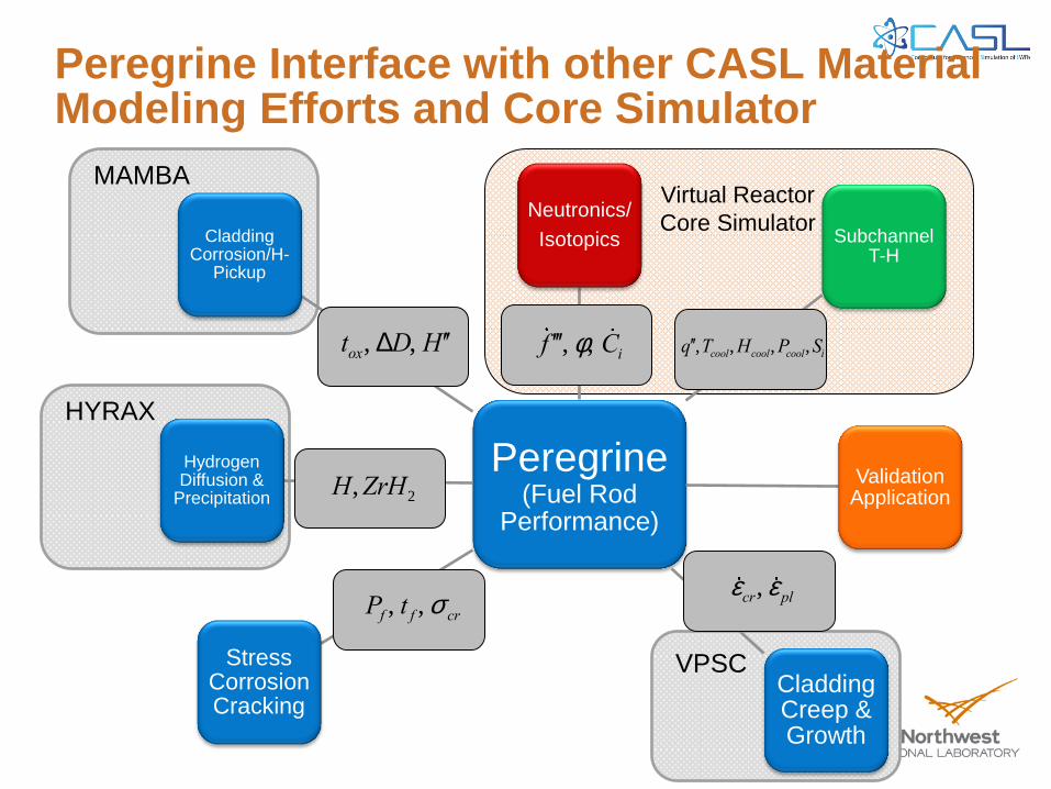
Peregrine Interface with other CASL Material Modeling Efforts and Core Simulator
Peregrine (Fuel Rod
Performance)
Neutronics/
Isotopics Subchannel T-H
Cladding Creep & Growth
Stress Corrosion Cracking
Validation Application
Hydrogen Diffusion &
Precipitation
Cladding Corrosion/H-
Pickup
¢¢¢f , f, Ci ¢¢q ,Tcool,Hcool,Pcool,Sitox, DD, ¢¢H
H,ZrH2
ecr, eplPf , t f , s cr
Virtual Reactor
Core Simulator
MAMBA
HYRAX
VPSC
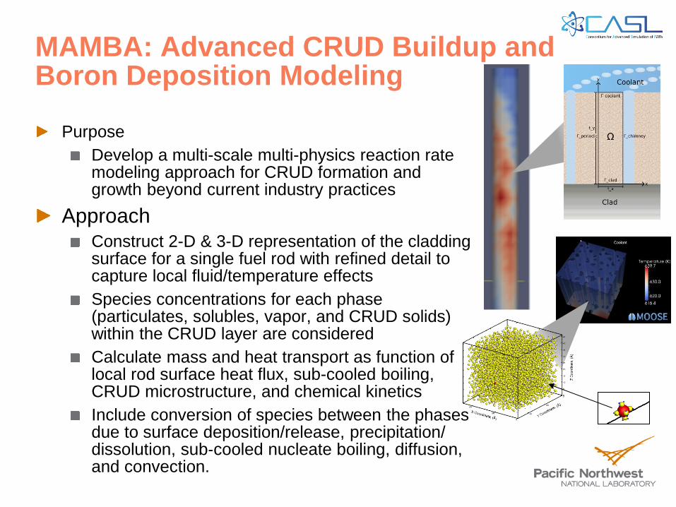
MAMBA: Advanced CRUD Buildup and Boron Deposition Modeling
Purpose
Develop a multi-scale multi-physics reaction rate modeling approach for CRUD formation and growth beyond current industry practices
Approach
Construct 2-D & 3-D representation of the cladding surface for a single fuel rod with refined detail to capture local fluid/temperature effects
Species concentrations for each phase (particulates, solubles, vapor, and CRUD solids) within the CRUD layer are considered
Calculate mass and heat transport as function of local rod surface heat flux, sub-cooled boiling, CRUD microstructure, and chemical kinetics
Include conversion of species between the phases due to surface deposition/release, precipitation/ dissolution, sub‐cooled nucleate boiling, diffusion, and convection.

MAMBA flow chart: phases, interfaces, and submodels
Primary Species:
C1 = Ni
C2 = Fe
C3 = Zr
C4 = Zn
C5 = B
C6 = Li
C7 = Cr
C8 = Co
O and H implied
Chemical kinetics mechanisms
will compute species concentrations
versus time for “local conditions” at
each “node” within computational cell
Vapor (SNB)
Solubles
CSi
Particulates
CPi
CRUD
CMi
CILC
Rates
Coolant Flow
and Chemistry
Transport
CIPS

MAMBA CRUD deposition model: 2D View
Colored contours:
normalized boron
concentration
Compute node and
volume element
Heat Transport between nodes: 3D non-linear,
iterative, numerical solution at each time step,
with local “sinks” due to boiling
CRUD/coolant interface is time
dependent (adaptive):
deposition & “erosion”
Thermodynamics and chemical kinetics
computed at each node and time step
Boiling induced convective &
diffusive transport between
nodes and coolant
Cladding Surface
Coolant Flow
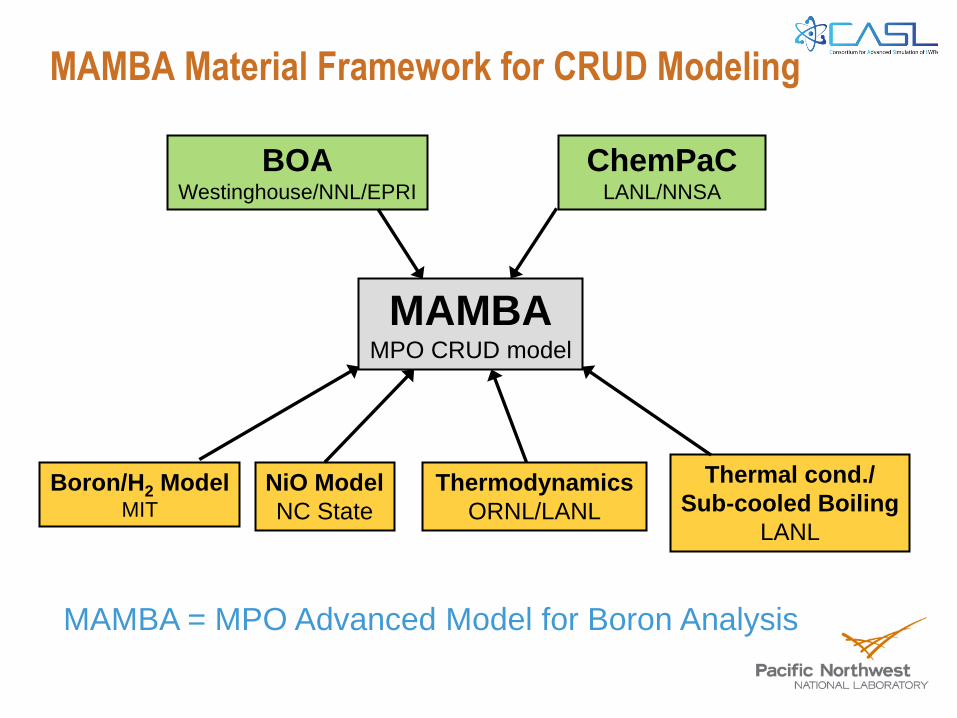
MAMBA Material Framework for CRUD Modeling
MAMBA MPO CRUD model
ChemPaC LANL/NNSA
BOA Westinghouse/NNL/EPRI
Boron/H2 Model MIT
NiO Model
NC State
Thermodynamics
ORNL/LANL
Thermal cond./
Sub-cooled Boiling
LANL
MAMBA = MPO Advanced Model for Boron Analysis

Lower Length Scale Modeling Activities in CASL – Important for Transients
High temperature thermal creep and creep rupture
Thermochemistry of coolant particulates/chemistry and cladding reactions for CRUD layer formation
CRUD layer deposition model that captures constituents, morphology, and thickness
Water side corrosion kinetics for oxide layer crystallography, morphology, and thickness
Hydrogen uptake, hydride formation, and redistribution
Xenon diffusion and bubble growth behavior in irradiated UO2 material


We can now predict defect-
dislocation interaction with high
accuracy, including effects that go
beyond anisotropic linear elasticity
BO transforms into
BS at ~ 0.008
Comparison of atomistics and continuum defect
energies for interstitials. Excellent agreement is
obtained for strains up to ~ 5% (full range not shown)
Types of self-interstitials
Defect energy in the field of a dislocation.
Away from the core, atomistics matches
continuum solution
Atomistics
captures
details
missed by
theory
Atomistic characterization of point defects in Zr
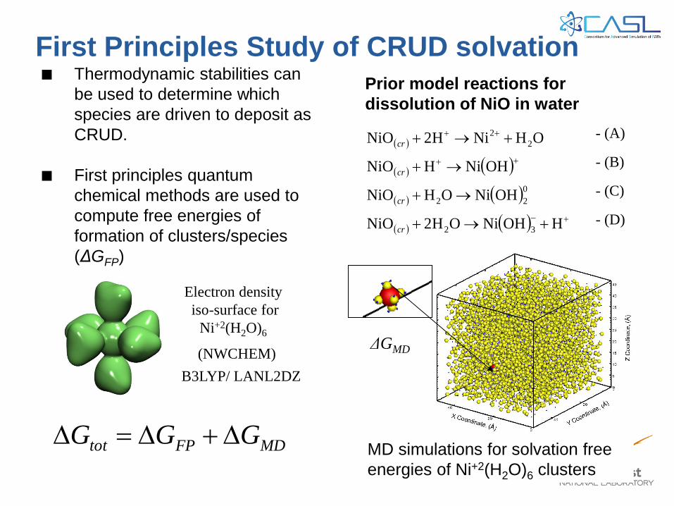
First Principles Study of CRUD solvation ■ Thermodynamic stabilities can
be used to determine which
species are driven to deposit as
CRUD.
■ First principles quantum
chemical methods are used to
compute free energies of
formation of clusters/species
(ΔGFP)
MDFPtot GGG
HOHNiOH2NiO
OHNiOHNiO
OHNiHNiO
OHNiH2NiO
32
0
22
2
2
cr
cr
cr
cr
Prior model reactions for
dissolution of NiO in water
- (A)
- (B)
- (C)
- (D)
Electron density
iso-surface for
Ni+2(H2O)6
(NWCHEM)
B3LYP/ LANL2DZ
ΔGMD
MD simulations for solvation free
energies of Ni+2(H2O)6 clusters

First Principles Analysis of Intermediate Temperature Mechanisms
Traditionally explained by enhanced
vacancy concentration according to:
However, this explanation relies
on a particular set of data that,
according to calculations, may not
be accurate.
D2 s2JVV
V Virr K /JV Z
TkFD
B
2.1expconstant2
Applying the same assumption as above
yields yields 3.17 eV. Interestingly this is
close to the high temperature regime.
Obtained by assuming:
JV exp 2.4
kBT
JXe exp Em
XeU2O EB
XeU2O
kBT
From DFT:
JV exp Em
VU2
kBT
Further analysis required, alternative mechanisms
may be important for intermediate T and high T.

25
3rd Annual DOE Review of CASL, Oak Ridge National Laboratory, Aug 13-14, 2013
• Evaluate Peregrine to calculate the thermal, mechanical, and irradiation behavior of UO2/Zr-alloy fuel rods
• Fuel temperature, cladding displacements, and fission gas release measurements from 14 fuel rods used in assessment
• Compare to Falcon results to understand performance of material and behavior models
• Peregrine is on par with industry standard codes (e.g. FALCON) up to 75 GWd/tU
• Reliably calculates fuel temperatures, cladding deformations, and fission gas release as function of environmental conditions
• Versatile framework to evaluate critical parameters and improved modeling approaches
Objective and Approach
Peregrine: Validation and Benchmark Evaluation of Integrated Fuel Performance Modeling Using Test Reactor Data and Falcon
Assessment
• Enhanced mechanistic models for UO2 thermal conductivity, Zircaloy creep and growth, pellet cracking and fragment relocation.
• Use lower length scale modeling to inform fission gas release kinetics
• Expand to 3-D and local effects modeling
Path Forward
CASL Milestone: L1.CASL.P7.02 Protected under CASL Multi-Party NDA No. 793IP
5-8
Figure 5-11 shows the comparison between the Peregrine calculations and the experimental
measurements following the ramp test for AN2. Overall, the model predictions track the axial variation of the diameter change reasonably well, although an apparent under-prediction of
cladding diameter change at ~200 mm corresponding to peak power location.
Figure 5-12 shows the comparison between the Peregrine predictions and the experimental
measurements following the RISØ ramp test for AN8. Similar to the result of AN2, the Peregrine
calculation agrees with the axial variation of cladding diameter changes but clearly under-predicts the deformation of the lower portion of the rod.
Figure 5-11 Peregrine Calculation of Post-ramp Cladding Diameter Change for AN2 Test Rod
Compared to the Measurement
Figure 5-12 Peregrine Calculation of Post-ramp Cladding Diameter Change for AN8 Test Rod
Compared to the Measurement
, 0.12!
, 0.1!
, 0.08!
, 0.06!
, 0.04!
, 0.02!
0!
0.02!
0! 100! 200! 300! 400! 500! 600! 700!
Chan
ge-in
-Cla
ddin
g-D
iam
eter
-(m
m)-
Axial-Position-(mm)-
Experiment!
Peregrine!
, 0.12!
, 0.1!
, 0.08!
, 0.06!
, 0.04!
, 0.02!
0!0! 100! 200! 300! 400! 500! 600! 700!
Chan
ge-in
-Cla
ddin
g-D
iam
eter
-(m
)-
Axial-Position-(mm)-
Experiment!
Peregrine!
CASL Milestone: L1.CASL.P7.02 Protected under CASL Multi-Party NDA No. 793IP
6-18
Figure 6-18 Comparison of Fission Gas Release Fraction between the Measurement and
Peregrine Calculations
Overall, the preliminary benchmark results for the tests case covering a number of operating
conditions have shown that Peregrine code has the general capability of modeling fission gas release. However, the modeling of fission gas release has been a challenging part in nuclear
fuel performance codes; existing models in fuel performance codes generally do not provide a
versatile capability of predicting fission gas release which could result from different fuel
materials at various operating and accident conditions. It can be seen that the combination of several models is necessary to account for different mechanisms involved in the fission gas
release process. Expansion of the validation database to include different operating regimes is
necessary to further test the capabilities of the mechanistic models in the Peregrine code and to identify the missing mechanisms in current models to make improvements. For example, the
current benchmark cases do not have cases with appreciable amount of fission gas release in
steady state operations except for IFA 505.5 rod1. Such cases, however, could be of more
relevant to the operating conditions of commercial reactor fuels. Further development of more physics-based fission gas release models is also of interest to reduce the reliance on the
empirical knowledge in current models and to develop/improve the predictability of fission gas
release model.
Current model validation is largely based on the total amount of measured FGR at the end of
life, which could have missed some important aspects of the fission gas release process such as the incubation period of thermal release, contribution of fission gas release from different fuel
microstructures, fuel restructuring at high burnup, et. al. Detailed PIE data of relative fractions of
isotopes and distribution of gaseous products in the fuel matrix are available in some
experiments. They have not been used in the benchmark due to the limitation of current models and the processing capability of the Peregrine code. They provide valuable information
regarding the fission gas release behavior; and it would be of interest to use such information to
assist the development of advanced modeling capability.
600 800 1000 1200 1400 1600 1800Measured Temperature (K)
600
800
1000
1200
1400
1600
1800
Calc
ula
ted
Tem
per
ature
(K
)
Peregrine
Falcon+/- 50 Degrees
Calculated vs. Measured Temperature
550 temperature
measurements
0 2 4 6 8 10 12Burnup (MWd/kgUO
2)
-30
-20
-10
0
10
20
30
40
Fuel
-Cla
ddin
g G
ap W
idth
(m
icro
ns)
Peregrine
Falcon
Annular FuelColumn
Clad Tube
Upper Plenum
High temperature Region
r
z
Not to scale
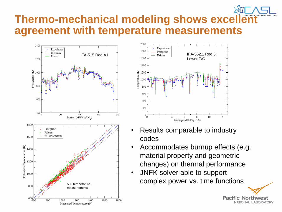
Thermo-mechanical modeling shows excellent agreement with temperature measurements
• Results comparable to industry
codes
• Accommodates burnup effects (e.g.
material property and geometric
changes) on thermal performance
• JNFK solver able to support
complex power vs. time functions
CASL Milestone: L1.CASL.P7.02 Protected under CASL Multi-Party NDA No. 793IP
4-35
Figure 4-5 Comparison of Peregrine and Falcon Calculated Temperatures with Measured
Temperatures as a Function of Burnup for IFA-562.1 Rod 5 at the Lower Thermocouple
Figure 4-6 Comparison of Peregrine and Falcon Calculated Temperatures with Measured
Temperatures as a Function of Burnup for IFA-562.1 Rod 5 at the Upper Thermocouple
600 800 1000 1200 1400 1600 1800Measured Temperature (K)
600
800
1000
1200
1400
1600
1800
Cal
cula
ted
Tem
per
ature
(K
)
Peregrine
Falcon+/- 50 Degrees
Calculated vs. Measured Temperature
550 temperature
measurements
CASL Milestone: L1.CASL.P7.02 Protected under CASL Multi-Party NDA No. 793IP
4-34
Figure 4-3 Comparison of Peregrine and Falcon Calculated Temperatures with Measured
Temperatures as a Function of Burnup for IFA-505, Rod 1
Figure 4-4 Comparison of Peregrine and Falcon Calculated Temperatures with Measured Temperatures as a Function of Burnup for IFA-515, Rod A1
IFA-515 Rod A1 IFA-562.1 Rod 5
Lower T/C
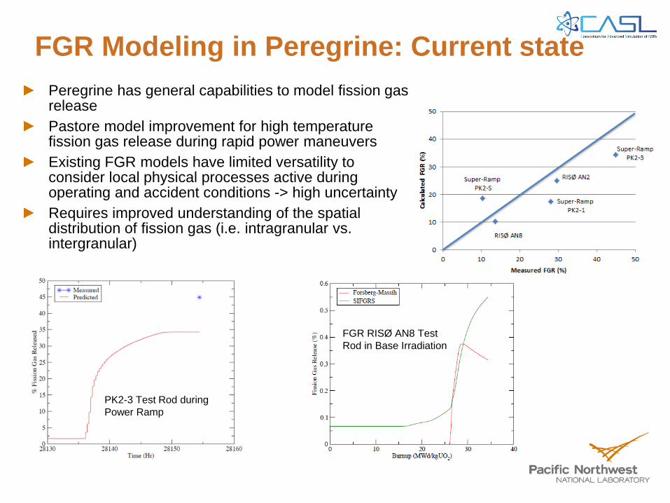
FGR Modeling in Peregrine: Current state
CASL Milestone: L1.CASL.P7.02 Protected under CASL Multi-Party NDA No. 793IP
6-10
Figure 6-9 Fission Gas Release Fraction Calculated using Different Models in Peregrine for
RISØ AN8 Test Rod in Base Irradiation
Results of fission gas release using Falcon and Peregrine code calculations for AN2 and AN8
test rods at the end of base irradiation are shown in Table 6-3. Measured fission gas release fraction based on sibling rods is also shown in Table 6-3 for comparison.
Falcon code predicts a much lower fission gas release fraction of 0.01% compared to the
measured 0.2%, which could be primarily caused by the athermal fission gas release. Falcon calculation is also lower than the athermal fission gas release of 0.07% calculated using the
Sifgrs model. Both the Sifgrs model and the Forsberg-Massih tend to predict higher fission gas
release; the amount of the thermal release alone is higher than the measurement.
Table 6-3 Comparison of FGR between Falcon, Peregrine, and Measurements for RISØ AN2
and AN8 Test Rods at the End of Base Irradiation
Calculated FGR (%) Measured
FGR (%) Falcon Peregrine
Sifgrs Sifgrs
athermal
Forsberg-Massih
AN2 0.01 1.0 0.07 0.6 0.2
AN8 NA 0.6 0.07 0.3 0.2
FGR RISØ AN8 Test
Rod in Base Irradiation
CASL Milestone: L1.CASL.P7.02 Protected under CASL Multi-Party NDA No. 793IP
6-18
Figure 6-18 Comparison of Fission Gas Release Fraction between the Measurement and
Peregrine Calculations
Overall, the preliminary benchmark results for the tests case covering a number of operating
conditions have shown that Peregrine code has the general capability of modeling fission gas release. However, the modeling of fission gas release has been a challenging part in nuclear
fuel performance codes; existing models in fuel performance codes generally do not provide a
versatile capability of predicting fission gas release which could result from different fuel
materials at various operating and accident conditions. It can be seen that the combination of several models is necessary to account for different mechanisms involved in the fission gas
release process. Expansion of the validation database to include different operating regimes is
necessary to further test the capabilities of the mechanistic models in the Peregrine code and to identify the missing mechanisms in current models to make improvements. For example, the
current benchmark cases do not have cases with appreciable amount of fission gas release in
steady state operations except for IFA 505.5 rod1. Such cases, however, could be of more
relevant to the operating conditions of commercial reactor fuels. Further development of more physics-based fission gas release models is also of interest to reduce the reliance on the
empirical knowledge in current models and to develop/improve the predictability of fission gas
release model.
Current model validation is largely based on the total amount of measured FGR at the end of
life, which could have missed some important aspects of the fission gas release process such as the incubation period of thermal release, contribution of fission gas release from different fuel
microstructures, fuel restructuring at high burnup, et. al. Detailed PIE data of relative fractions of
isotopes and distribution of gaseous products in the fuel matrix are available in some
experiments. They have not been used in the benchmark due to the limitation of current models and the processing capability of the Peregrine code. They provide valuable information
regarding the fission gas release behavior; and it would be of interest to use such information to
assist the development of advanced modeling capability.
PK2-3 Test Rod during
Power Ramp
Peregrine has general capabilities to model fission gas release
Pastore model improvement for high temperature fission gas release during rapid power maneuvers
Existing FGR models have limited versatility to consider local physical processes active during operating and accident conditions -> high uncertainty
Requires improved understanding of the spatial distribution of fission gas (i.e. intragranular vs. intergranular)

MAMBA Benchmark/Validation

MAMBA: Multi-rod CRUD Modeling
“MAMBA” calculates cladding
surface heat flux, crud surface
temperature, and is coupled
DeCART (neutronics) / STAR-
CCM+ (thermal-hydraulics)
calculation
Typical crud loading in a PWR fuel
assembly ( NEI, 2012)
The simulation produced findings useful to PWRs :
• Significant azimuthal temperature variations on the
cladding surface (see right)
• Varying crud deposition and erosion rates resulting in
streak deposits (observed in operating PWRs, see right)
• Cladding “hot spots” were observed for thicker crud
This new coupled simulation capability is still under
development and hence has only been qualitatively
validated. Comparisons with out-of-pile data currently
underway
Flow

Transient Modeling in CASL – RIA Demo
Pellet Burnup - 75 GWd/tU Deposited Enthalpy ~120 cal/gm
Fast Fluence ~ 1.2x10²³ n/cm2-s

Transient Modeling Activities in CASL
Coupling with pin-resolved neutronics to evaluate impact of non-uniform power deposition within the pellet
Requires localized 3-D modeling of temperature, mechanical loads, and
Coupling MAMBA and Peregrine to improve corrosion and CRUD layer distributions
Needed to evaluate the consequences of cracking and spalling of the corrosion layer thickness under rapid loading conditions
Coupling with subchannel thermal-hydrauliccs and computational fluid dynamics
Improve local heat transfer conditions between cladding to coolant
Developing more mechanistic material models for high temperature mechanical and chemical reaction behavior
High strain rate and large deformation response
Fracture/Failure mode response
Mechanistic fission gas diffusion, bubble growth, interlinkage, and release
Establish distribution of fission gas prior to a transient
Improve fission gas release kinetics for rapidly changing conditions

Summary/Conclusions - 1
CASL is developing state-of-the-art fuel behavior modeling capabilities using a multi-scale, multi-physics approach
Identify the conditions and important fundamental mechanisms that influence material performance or behavior response
Use microscale modeling to improve representations for key material properties
Applying this approach to PCI failure and CRUD formation
CASL is working on capabilities for advanced fuel behavior modeling for off-normal conditions, particularly RIA and LOCA
Mechanistic cladding deformation model
coupling Peregrine and MAMBA to provide a more accurate distribution of cladding corrosion and CRUD layer distribution
improved fission gas diffusion kinetics needed to define intragranular and intergranular fission gas bubble distributions

Summary/Conclusions - 2
Peregrine and MAMBA benchmarking and validation activities provide confidence in the development of the fuel performance modeling capabilities
Quantitative and qualitative evaluations with measured data and industry codes show excellent results
Comparisons with data highlight the challenges modeling complex thermal and mechanical behavior of irradiated fuel performance
Areas of improvement include, pellet cracking and relocation, fission gas retention and release, cladding creep and growth, cladding oxidation and hydride formation and growth
Application of advanced modeling methods to LWR transient conditions could address
the impact of non-uniform power deposition within the pellet
the consequences of cracking and spalling of the corrosion layer thickness under rapid loading conditions,
the important role of cladding to coolant heat transfer
high temperature mechanical and chemical reaction behavior

Modeling Transient Behavior: Loss-of-Coolant Accidents
Proceedings of the 2005 Water Reactor Fuel Performance Meeting
Kyoto, Japan, October 2-6, 2005
Paper 1076/Track 5
6. JAERI LOCA Tests
An experimental program related to the high
burnup fuel behavior during a LOCA has been
initiated at the Japan Atomic Energy Research
Institute (JAERI). The objectives of this program are
to evaluate the influence of high burnup effects on
fuel behavior under LOCA conditions and to provide
basic data to assess applicability of the current
criteria for cladding embitterment to a higher burnup
range. The program consists of Zircaloy cladding
oxidation tests, integral tests of rod-burst, oxidation
and rod thermal shock by quenching, and related
material properties tests. As a part of the program,
integral thermal shock tests simulating the whole
LOCA sequence were conducted with Zircaloy-4 fuel
rod cladding, irradiated to 39 and 44GWd/tU in a
PWR. The test rod was quenched with axial restraint
to represent a possible condition of fuel rod locked
between two spacer grid positions. In the present
study, the maximum load was limited to about 540 N
and was maintained by the automatic load adjusting
operation of the tensile testing machine. The 540 N is
based on the measurement of resistant load between
deformed or chemically interacted cladding and
spacer grid14. For these tests, the UO2 pellets were
removed and alumina dummy pellets were loaded in
the 190mm-long cladding, and the rod was
pressurized to about 5 MPa with Ar gas at room
temperature. To date, three tests have been conducted
on irradiated claddings with the initial oxide
thickness between 18 to 25 µm and hydrogen
concentrations is estimated to be 200 to 300 ppm.
7. FALCON analysis of JAERI LOCA Tests
A PWR fuel rod, irradiated to 44 GWd/tU at
Takahama Unit-3 reactor was selected for analysis
with FALCON to demonstrate the ability of the code
to calculate the cladding ballooning and burst
behavior as well as to calculate the thermal shock
load resulted from the axial restraints during the
quenching. An axisymmetric r-z finite element grid
was used for this analysis. Axial constraint boundary
conditions are applied at the lower endcap to
represent the lower mechanical connection to the
universal testing machine. The top endcap is free to
move in the axial direction during the heat up and
isothermal oxidation period. At the beginning of the
cooling phase, the FALCON calculation was
restarted with a fully restrained boundary condition at
the top end cap, which restricts the movement of the
top and bottom endcaps in the axial direction.
FALCON’s versatile and highly user-oriented restart
capability allows the user to retrieve the necessary
data from a previous analysis and to continue the
analysis with a new set of boundary conditions. As a
result, it is possible to model the fully restrained axial
boundary conditions at the beginning of the cooling
phase and to calculate the tensile loading resulting
from the restriction on the cladding shrinkage during
the quench process. However, at this time FALCON
cannot model the partially restrained boundary
condition of the JAERI experiment. Further
modification of the upper end plug displacement
constraint boundary conditions is necessary to model
the partial restrained conditions in order to limit the
maximum axial loading, as done in several of the
JAERI tests.
Figure 11 compares the FALCON calculation of
cladding temperatures and cladding axial loading
with the measurements. FALCON calculates the
cladding temperatures at the thermocouple locations.
Four thermocouples are spot-welded on the outer
surface of the cladding; thermocouple 2 is at the mid-
height position, TC1 and TC3 are 40 mm above and
below from the rod middle respectively, and TC4 is
above 20 mm from the rod mid section.
Time (s)
0 100 200 300 400 500 600
Cla
dd
ing
Te
mp
era
ture
(oC
)0
200
400
600
800
1000
1200
1400
Ax
ial
Lo
ad
(N
)
0
500
1000
1500
2000
2500
3000
Measured Temp
Calculated TC 3
Calculated TC 2
Calculated TC 4
Calculated TC 1
Measured Load
Calculated load
Figure 11. FALCON Comparison to JAERI Test-2
Temperature and Axial Load Measurements
The cladding temperature is nearly uniform in the 40-
mm region at rod center, and the axial temperature
difference is about 5oC in this region. The cladding
tube balloons and ruptures at measured temperatures
ranging between 780 to 830oC during the heat up.
The rod is isothermally oxidized after the rupture.
Isothermal oxidation temperature and time ranges
from 1160 to 1200oC and from 130 to 300 s. The rod
is cooled in a steam flow to about 700oC and is
finally quenched with water flooding from the
bottom. The results presented in Figure 11 are for a
test rod that was quenched under partially restrained
conditions, where the maximum loading was limited
to 540 N. The FALCON calculated axial load reaches
about 2500 N at the end of the quenching using full
axial restraint. Fully restrained experiments
performed in the JAERI LOCA test facilities
9 808
0.00E+00
1.00E-05
2.00E-05
3.00E-05
4.00E-05
5.00E-05
6.00E-05
7.00E-05
8.00E-05
0 40 80 120 160 200 240 280 320
Inn
er
alp
ha
la
ye
r th
ickn
es
s (
m)
Time (sec)
HBR Zry-4 Test ID 7
Bond layer = 15 micron
Bond layer = 7 micron
HBR Zry-4 Test ID 8
Alp
ha L
ayer R
an
ge
for
Initia
l Oxid
e T
hic
kness
Fig. 6 Prediction of inner s-phase layer formation of high
burnup fuel cladding in one-sided steam oxidation
221
(a)
(b)
Figure 157. Comparison of Zry-4 samples oxidized (one-sided) in steam at 1200ºC to 5% CP-ECR: (a)
as-fabricated HBR-type Zry-4 at 4 mm from sample midplane and (b) high-burnup HBR Zry-4 at 4 mm
from sample midplane.
Nagase, JNST Vol 42, no. 2, Feb 2005
NUREG/CR-6967
Jahingir, WRFPM 2005
Liu, WRFPM 2011

Fuel Behavior Mechanisms Important for RIA:
Fuel rod initial conditions RIA Phase 1
Near-Adiabatic Energy Deposition
RIA Phase 2
Energy Deposition with Heat Transfer
Residual pellet-cladding gap thickness/fuel-
clad bonding
Thermal expansion of cracked pellet structure
(crack volume closure rates)
Fission gas behavior in both grain boundary
and intragranular bubbles
Cracked pellet state/fragment distribution Gap mechanical contact and thermal
conductance
Transient fission gas release kinetics
Fission gas distribution in pellet: grain
boundaries and grain concentrations
Fuel fragmentation and dispersal kinetics after
cladding fracture
Axial gas transport kinetics within/adjacent to
fuel column (localized pressurization)
Fission gas release into the gap and plenum Fuel fragment coolant interaction and pressure
generation
Fuel fragmentation and dispersal kinetics
Fissile isotope/burnup distribution Effective fuel thermal conductivity
Cladding corrosion and CRUD layer build up Cladding fast strain rate behavior/plasticity Cladding thermal annealing/plastic behavior
recovery
Cladding hydrogen uptake/content, distribution
of hydrides, etc.
Fracture and spallation of oxide and crud layer Thermal creep and creep rupture
Cladding creep deformations Cladding crack formation and growth
(displacement controlled deformation)
High temperature oxidation (Oxygen uptake
and diffusion in cladding)
Cladding Irradiation damage (dislocation
densities, second phase particle
amorphization, etc.)
Thermal shock stress distributions in cladding
during quench/rewetting
Boron deposition/Coolant chemistry Material mechanical behavior as function of
phase (ZrO2, high O alpha, and prior beta)
Post-Departure from Nucleate (DNB) clad-to-
coolant heat transfer

Interfaces to couple Fuel Performance with Neutronics and Thermal-Hydraulics
Neutronics Thermal-
Hydraulics
Coolant Gamma Heating
Moderator Temperature
and Density
Hea
t Tra
nsfe
r C
oeffi
cien
ts
Coo
lant
Tem
pera
ture
s
Total Pow
er Density (W
/m3)
/Fast N
eutron flux (>1 M
ev)
Fuel a
nd clad
tem
perature
distribution
(radia
l ave
rage)
Peregrine
Cla
ddin
g Su
rface
Tem
pera
ture
Cla
ddin
g Su
rface
Hea
t Flu
x