us. patent a r. 27 2010 sheet 1 of4
TRANSCRIPT

US007706211B2
(12) Umted States Patent (10) Patent N0.2 US 7,706,211 B2 Bakulin et al. (45) Date of Patent: Apr. 27, 2010
(54) METHOD OF DETERMINING A SEISMIC 2008/0225641 A1* 9/2008 Van Manen et a1. ......... .. 367/38
VELOCITY PROFILE
(75) Inventors: Andrey Victorovich Bakulin, Houston, FOREIGN PATENT DOCUMENTS
TX (US); Rodney William Calvert, EP 443234 Al 8/1991 Houston, TX (US); Albena AleXandrova W0 WO2005054900 A1 600% Mateeva, Houston, TX (US)
(73) Assignee: Shell Oil Company, Houston, TX (US) OTHER PUBLICATIONS
( * ) NOIiCBZ subject 10 any disclaimer, the term OfIhiS Bakulin, A and Calvert R., “virtual Source: New Method for Imaging patent is extended or adjusted under 35 and 4D below Complex Overburden”, 74th annual meeting SEG, U_S_C_ 154(1)) by 562 days_ Expanded Abstracts pp. 2477-2480(2004).
(21) App1.No.: 11/671,310 (Commued) ' Primary Examinerilack W. Keith
(22) Flledi Feb- 5, 2007 Assistant ExamineriKrystine Saito
(65) Prior Publication Data (57) ABSTRACT
US 2007/0195643 A1 Aug. 23, 2007 _ _ A seismic velocity pro?le in a region of interest in a subsur
Related U-s-APPhcatmn Data face formation is determined using at least the following
(60) Provisional application No. 60/765,563, ?led on Feb. Steps' 6, 2006, provisional application No_ 60/866,950’ ?led (a) Activating a seismic source at a location n, thereby excit on NOV_ 22, 2006' ing a wave in the subsurface formation.
(b) Recording a wave signal trace unm(t) against time t, at a (51) Int_ CL seismic receiver m.
G01 V 1/00 (2006.01) (c) Recording a wave signal trace unk(t) against time t at a (52) US. Cl. .................................... .. . 367/38; 367/73 Seismic receiver k
(58) Field of Classi?cation Search ................. .. 367/38, ((0 Cross Correlanng the Wave Slgnal traces unm?) and unlit) 367/73 to Obtain WWW/,0)
See application ?le for complete search history. (e) Repeating these steps, for different locations 11; _ (f) Summing uco'wnmnk?) over all locations n, to obtain a
(56) References Cited
U.S. PATENT DOCUMENTS
4,832,148 A * 5/1989 Becker et a1. . . . . . . . . . . .. 181/104
5,481,501 A * 1/1996 Blakeslee et al. 367/57
6,747,915 B2 * 6/2004 Calvert ......... .. 367/46
6,807,487 B2 * 10/2004 Khan .... .. 702/16
2003/0076740 A1 4/2003 Calvert 367/38
2003/0083820 A1* 5/2003 Ren et al. ................... .. 702/18
8 x \ ,
i Y \\\\\\\
signal trace uvsmk(t) which corresponds to the signal received by the seismic receiver k from the virtual source at the position of seismic receiver m;
(g) Deriving the seismic velocity based on the time of ?rst arrival of the wave in uvsmk(t) and the predetermined dis tance between the seismic receiver rn and the seismic receiver k.
14 Claims, 4 Drawing Sheets
Ill/Q

US 7,706,211 B2 Page 2
OTHER PUBLICATIONS
Bakulin, A and Calvert R., “virtual Shear Source: New Method for Shear Wave Seismic Surveys”, 75th annual meeting SEG, Expanded Abstracts pp. 2633-2636(2005). Bakulin, A and Calvert R., “The virtual Source Method: Theory and case study”, 2006 Geophysics. Zhao, X et al“Shear Waves from near-offset VSP survey and appli cations”, 75th annual meeting SEG, Expanded Abstracts pp. 2629 2632 (2005).
R. Allnor et al “Inversion of seismic surface Waves for shear Wave
velocities”, 67th annual meeting SEG, Expanded Abstracts pp. 1921 1924 (1997). “Well Logging in non-technical language”, by David Earl Johnson and Kathryn E. Pile pp. 167-168, published 2002 by PennWell Books, ISBN: 0878148256.
* cited by examiner
US. Patent A r. 27 2010 Sheet 1 of4

US. Patent Apr. 27, 2010 Sheet 2 014 US 7,706,211 B2

US. Patent Apr. 27, 2010 Sheet 3 014 US 7,706,211 B2
zmmlmnm E
:353 Hi
A
2 raw 5 E0288 m>d
000v new mom

US. Patent Apr. 27, 2010 Sheet 4 014 US 7,706,211 B2
3.3
6.66 6.45 6,30
6.60 6.30 6.45
(1 (km)

US 7,706,211 B2 1
METHOD OF DETERMININGA SEISMIC VELOCITY PROFILE
CROSS REFERENCE TO PRIOR APPLICATION
The present application claims the bene?t of US. Provi sional Application No. 60/765,563, ?led 6 Feb. 2006, and of US. Provisional Application No. 60/866,950, ?led 22 Nov. 2006.
FIELD OF THE INVENTION
In one aspect, the present invention relates to a method of determining a seismic velocity pro?le in a subsurface forma tion.
BACKGROUND OF THE INVENTION
A seismic velocity pro?le in a subsurface formation may be obtained employing the so-called check shot (also knoWn as “Well shoot” or “velocity survey”) technique. The check shot technique is described in, for instance, on pages 167 and 168 of “Well Logging in non-technical language,” by David Earl Johnson and Kathryne E. Pile, published 2002 by PennWell Books, ISBN 0878148256. A conventional check shot technique includes generating
multiple shots from a seismic source located in a selected position, usually close to a Wellhead. Shots are detected at different locations along a bore hole extending beloW the Wellhead, by a receiver that is moved along the bore hole.
Alternatively, a set comprising a plurality of receivers may be located in the bore hole, in Which case only a single shot Would be required. A complex overburden may lead to erroneous velocity
pro?les When conventional check-shots and Zero-offset ver tical seismic pro?les (VSP) are used. When there is a complex transmission medium betWeen
the set of seismic sources and the region of interest, such as for example a complex overburden, the extraction of velocity pro?les from check shots is a challenging task. First arrival Waveforms may be distorted and dif?cult to pick as a result of the complex transmission medium, and the fastest arrival may not even come along the shortest path betWeen the source and the receiver, thus making it dif?cult to relate arrival time to velocity.
This could be alleviated by placing the source in the bore hole, or Well, so that the travel-path of the ?rst arrival is short and close to a straight line betWeen the source and the receiver. In practice, hoWever, it is cumbersome to place and operate a physical source doWnhole.
Another dif?culty With conventional check shots is that they measure only P-Wave velocity from ?rst arrivals. Shear Waves, even if emitted from the surface source or generated by P-S conversions in the overburden, arrive later, and are dif?cult to unravel and pick. Hence a shear Wave check shot is dif?cult, if not impossible, to obtain using conventional check shot techniques.
SUMMARY OF THE INVENTION
In accordance With one aspect of the invention, there is provided a method of determining a seismic velocity in a subsurface formation, comprising the steps of
(a) providing tWo or more seismic receivers in the subsurface formation at predetermined distances from one another;
20
25
30
35
40
45
50
55
60
65
2 (b) selecting a seismic receiver m from the tWo or more seismic receivers as the location of a virtual source;
(c) selecting another seismic receiver k from the tWo or more seismic receivers;
(d) activating a seismic source at a location n, thereby exciting a Wave in the subsurface formation;
(e) recording a Wave signal trace unm(t) against time t, at the seismic receiver m;
(f) recording a Wave signal trace unk(t) against time t at the seismic receiver k;
(g) cross correlating the Wave signal traces unm(t) and unk(t) to obtain uco'wnmnk?);
(h) repeating steps (d) to (g) inclusive, for different locations 11;
con v (i) summing u nmnk(t) over all locations n, to obtain a signal trace uvsmk(t) Which corresponds to the signal received by the seismic receiver k from the virtual source at the position of seismic receiver m;
(j) deriving the seismic velocity based on the time of ?rst arrival of the Wave in uvsmk(t) and the predetermined distance betWeen the seismic receiver m and the seismic receiver k. A full seismic velocity pro?le may be determined by
repeating the steps (c) to (i) inclusive, using a different seis mic receiver k at a different predetermined distance from the seismic receiver m, and deriving, in step (i), the seismic velocity pro?le based on the times of the ?rst arrivals of the Wave in uvsmk(t) for all k.
BRIEF DESCRIPTION OF THE DRAWINGS
The invention Will noW be illustrated in more detail, by Way of example With reference to the draWing, Wherein:
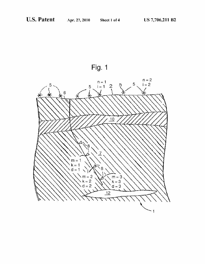
FIG. 1 shoWs schematically and not to scale an arrange ment of seismic sources and seismic receivers in a deviated bore hole, for carrying out embodiments of the method of the present invention;
FIG. 2 shoWs schematically and not to scale an arrange ment of seismic sources and seismic receivers in a vertical bore hole for carrying out virtual check shots;
FIG. 3 shoWs a common virtual shot gather With (a) a P-Wave virtual source and (b) an S-Wave virtual source;
FIG. 4 shoWs a comparison betWeen the virtual check shot of FIG. 3a, a conventional check shot, and a smoothed sonic log; and
FIG. 5 shoWs a graphic comparison betWeen S-Wave and P-Wave virtual check shots (of FIGS. 3b and 3a) versus smoothed sonic logs.
DETAILED DESCRIPTION OF THE EMBODIMENTS
The present virtual check shot technique overcomes the challenges associated With conventional checkshot tech niques, by redatuming the seismic traces to create a virtual source at one or more doWnhole seismic receivers, Which may comprise a geophone. When the seismic receiver at the loca tion of the virtual source and the other seismic receivers are located beloW the most complex part of the section, the obtained velocity pro?les are not distorted by the overburden. By measuring the travel time of a ?rst arrival Wave from the
seismic receiver at the location of the virtual source to another seismic receiver, a local seismic velocity may be determined. This Will hereinafter be referred to as a virtual check shot.

US 7,706,211 B2 3
When the travel times of the ?rst arrival Waves from the virtual source to a number of seismic receivers below it, a seismic velocity pro?le may be constructed that is insensitive to overburden complexity. The virtual check shot can correct for overburden of any complexity since no velocity informa tion betWeen the surface and the seismic receivers is required.
Furthermore, bene?t may be made of P-S conversions that often occur in the overburden, to create a pure Shear Virtual Source in the borehole. The ?rst arrival from such a source, Which is easy to pick, Would be an S-Wave, yielding a shear velocity pro?le.
In US. Pat. No. 6,747,915 a method has been reported for seismic imaging, employing the signals from a set comprising a plurality of seismic receivers in such a Way that it appears as if the seismic Waves originate from a source at the location of one of the seismic receivers located doWn hole. Such a source is then called a virtual source, to distinguish it from a real source. US. Pat. No. 6,747,915 describes amethod ofseismic imaging a subsurface formation using a set of seismic sources i and a set of seismic receivers j, Wherein there is a complex transmission medium betWeen the tWo sets, Which method comprises the steps of:
(a) recording With the set of seismic receivers j the signals uZ-J-(t) obtained from activating the set of seismic sources i;
(b) selecting a seismic receiver m as the location of a virtual
source;
(c) selecting a seismic receiver k, Wherein k is in a predeter mined range around the position of seismic receiver m;
(d) selecting a seismic source n from the seismic sources i;
(e) time-reversing at least a part of the signal unm(t) to obtain a time-reversed signal unm(—t);
(f) convolving the time-reversed signal unm(—t) With the sig nal unk(t) to obtain the convolved signal uc°"v....k<ow.m<-o®11.110; (g) selecting a next source n, repeating steps (e) and
(f) until a predetermined number of sources have had their turn;
(h) summing the convolved signals over the seismic sources n to obtain a signal uvsmk(r):znuco"vmnk(r), Where uvsmk(t) is the signal received by a seismic receiver at the position k from a virtual source at the position of seismic receiver m;
(i) repeating steps (c) through (h) over k;
(j) repeating steps (b) through (i) over In to generate a seismic survey With virtual sources In and receivers k; and
(k) further processing the virtual source signals to obtain a seismic image.
In the present speci?cation, including the claims, the sym bol @ means convolution.
The above described virtual source (VS) method thus takes multi-offset seismic data and converts that to data that Would have been recorded in the same seismic receivers if the source Would have been in the borehole, at a location coinciding With an existing seismic receiver. The conversion can be entirely data-driveniit is not needed have a velocity model of the medium to create VS data.
US. Pat. No. 6,747,915 does not disclose checkshots. It has noW been contemplated that the method broadly intro duced in US. Pat. No. 6,747,915 may form the basis for obtaining virtual check shots, including S-Wave virtual check shots as Well as P-Wave virtual check shots.
20
25
30
35
40
45
50
55
60
65
4 The present speci?cation contemplates applying selected
features from the method broadly introduced in US. Pat. No. 6,747,915 for obtaining virtual check shots to determine velocity pro?les similar to What Would be the case for con ventional check shots but employing a virtual source.
FIG. 1 shoWs schematically and not to scale a section 1 of the earth having a surface 2. At the surface 2 are located seismic sources 5, and in a borehole 6 are located seismic receivers 8. The part of the borehole 6 in Which the seismic receivers 8 are located, lies in a region of interest 7 in a sub surface formation under a complex transmission medium in the form of complex overburden 1 0. A re?ector 12 may also be located in the region of interest, of Which a seismic image may be made. The ?rst step of the method according to the present inven
tion is conventional: recording With a set of the seismic receivers 8 the signals obtained from activating a set of the seismic sources 5. Equivalent to activating a set of seismic sources is respectively activating a single seismic source at various different locations.
It Will be understood that the seismic Wave that is emitted by a seismic source 5 at a location n and received by a seismic receiver 8 at a location j generates a signal varying With time, Which signal consists of a part that comes from the seismic Wave that passes through the complex overburden 10 toWards the seismic receiver 8 and a part that comes from Waves that travel all the Way doWn to the re?ector 12 and that are re?ected back to the seismic receiver 8. The ?rst part of the signal is called the direct part of the signal, Which Would typically be relevant for check shots. The latter part of the signal contains valuable target information, typically relevant for seismic imaging. It is an object of the present invention to suppress distortions in the direct part of the signal caused by the seismic Waves travelling through the complex overburden 10.
In the formulae that Will be used to explain the invention, the signals can be referred using the symbol u5i,8j(t), Wherein 5i refers to a selected seismic source 5 and 8j to a selected seismic receiver 8; hoWever, for the sake of clarity the ‘5’ and the ‘8’ Will be left out from the symbol. Thus the signals are correspondingly identi?ed as uZ-J-(t), Wherein i refers to a seis mic source and j to a seismic receiver.
In order to suppress the distortions, Applicant proposes to designate one of the seismic receivers 8 as a virtual source at the position of that seismic receiver, and to treat (redatum) the signals uZ-J-(t) such that a signal is obtained that originates from Waves travelling from the virtual source positioned at seismic receiver 8.
Thus the next step of the method according to the present invention is selecting a seismic receiver 8m as the location of a virtual source.
Then a seismic source 511 is selected from the seismic sources 5i. From the signals uZ-J-(t) the signal unm(t) is selected and at least a part of the signal trace unm(t) is time-reversed to obtain time-reversed signal trace unm(—t). Time reversal is just trace re?ection about time Zero, thus a trace from time 0 to time t becomes from time —t to time 0. An example of the part of the signal that is time-reversed is the signal due to the direct Wave, Which is that part of the signal that is received With seismic receiver 8m that comes from the seismic Wave directly travelling from the source 511 toWards the seismic receiver 8m through the complex overburden 10.
The virtual source is assumed to be at the position of the seismic receiver 8m, and it is an object to reconstruct What Would be the direct Wave betWeen the location 8m and 8k if a real seismic source Would have been positioned at location 8m. It is an object to obtain such a virtual signal, that origi

US 7,706,211 B2 5
nates from the virtual source In and is received at a seismic receiver 8k, from the signals from the sources 511. Best results are achieved When the source aperture is such that the energy generated by the seismic sources 5i passes through both the seismic receiver 8m (the one that Was designated as the loca tion of the virtual source) and the seismic receivers 8k (i.e. along the borehole 6).
Having selected the seismic receiver 8k, Whereby k is at a predetermined range around the position of seismic receiver 8m, the time-reversed signal unm(—t) is convolved With the signal unk(t) to obtain the convolved signal ucowwmkomx-oéb11.40.
In order to get the convolved signals for the seismic sources n, a next source n (or location) is selected, and the above steps, Which result in the convolved signal, are repeated. Then the convolved signals are summed over the seismic sources n (or locations n) to obtain a signal trace uvsmk(t):znuco"vmnk(r), Which may be referred to as a virtual signal trace. The virtual signal uvsmk(t) is the signal received by a seismic receiver at the position k from a virtual source at the position of seismic receiver m. This signal is free from distortions that originate from the direct Wave travelling through the complex overbur den 10.
It is noW contemplated that it is also possible, as Will next be explained, to extract a seismic velocity pro?le from the signals by constructing a “virtual checkshot”, employing the virtual source. “Virtual checkshots” may be generated from multi-offset seismic data, using signals from surface sources into doWn-hole seismic receivers, including conventional Walk-aWay (WAW) vertical seismic pro?ling (VSP) data, 3D (vertical) seismic pro?ling data, or any other suitable multiple offset source con?guration.
These ideas have been tested by Applicants, on an example data set from a sub-salt prospect in the deepWater Gulf of Mexico (GOM). Velocity pro?les of P- and S-Wave velocities have been obtained that are in good agreement With sonic logs under salt at more than 7 km depth.
The example data set Was acquired employing sources in a Walk-aWay line, and seismic receivers in a vertical Well through a complex overburden including a massive salt body 15, in deepWater as schematically shoWn in FIG. 2. The salt body 15 is located in various other earth formation layers 14a to 14h.A seismic receiver tool comprising seismic receivers 8 Was loWered in a vertical bore hole 16 associated With the vertical Well. A shot line of the seismic sources 5 Was pro vided beloW the Water line 3. The surface 2 forms the seabed. The extent of the shot line Was 612 shot points at 30 m (100 ft) spacing. An airgun Was used as the seismic source 5.
A survey Was shot in four passes of the same shot line, With four receiver tool settings, giving a total of 96 receiver depths (4><24). About tWo-thirds of the seismic receivers 8 Were in the salt body 15, near its base, and the rest Were beloW the salt
(FIG. 2). Velocity estimation Was, in the present examples, per
formed using only receivers from the same tool setting [30 m (100 ft) spacing]. HoWever, the receiver tool may be loWered by an amount corresponding to a non-integer fraction of the receiver spacing, such that the receivers in consecutive runs may be interlaced to provide a smaller effective spacing, of for instance half the receiver spacing Within a tool corre sponding to 15 m (50 ft) for the present receiver tool. Possible time shifts betWeen the acquisition lines should be docu mented and corrected for.
The folloWing steps alloW to create a virtual source at seismic receiver 8m and “record” the virtual signal transmit ted from that virtual source at seismic receiver 8k:
20
25
30
35
40
45
50
55
60
65
6 Taking a signal trace unm(t) corresponding to activating the
seismic source at location n (shot n) and recording at seismic receiver 8m
optionally gating the ?rst arrival and/ or optionally Weigh ing the signal and/or optionally applying a Wave ?eld sepa ration;
Cross-correlating the, optionally gated, Weighed, Wave ?eld separated, part of the trace With part of or the Whole trace unk(t) induced by the shot at seismic receiver 8k;
repeating for all surface shots at different locations n; summing the obtained cross-correlations over all surface
shots n.
This yields the trace from virtual source 8m to seismic receiver 8k. Reference is also made to an article byA. Bakulin and R. Calvert entitled “The virtual source method: theory and case study”, as published in “Geophysics”, Vol. 71(4), pages Sl139-Sl150. The contents of the article are herein incorporated by reference.
It is remarked that the gate siZe and position does not matter much, as long as it captures most of the doWn-going energy of the desired modeiin this case P-Wave. Moreover, the exact locations of the seismic sources need not be knoWn due to the summing of multi-offset cross correlations. As is knoWn, cross correlation is equivalent to convolution
With a time-reversed trace.
Example 1
P-Wave Virtual Checkshot
To create the P-Wave virtual source, the present example uses as input the vertical (Z) component of the VSP data. A virtual source Was created at every receiver depth. A common virtual shot gather With a P-Wave virtual source (PVS) located at the top-most receiver location is shoWn in FIG. 3(a). FIG. 3(a) thus shoWs the virtual signal traces uvsmk(t) for m:1 and various kranging from 2 to 96. The gaps at traces k:12-13 and k:60-61 are caused by dead receivers. The virtual source “?res” a Zero-phase impulse at time
t:100 ms. The ?rst arrival on the virtual signal traces is clear and easy to pick. Only picks on receivers from the same tool setting [30 m (exactly 100 ft) apart] Were used for interval velocity estimation. A linear ?t to the ?rst arrival moveout provides the folloWing P-Wave velocity estimate in the region of interest: Vpz2.82 km/s (9400 ft/ s). The region of interest in the example is beloW the salt body 15.
FIG. 4 plots P-Wave velocity Vp, against vertical depth d, after conversion from feet to km using 1 kft:0.30 km. FIG. 4 shoWs a comparison of the virtual check shot (line 20) as obtained above, With a standard check shot (line 21) and a sonic log (line 22) smoothed to the present VSP resolution of 30 m (100 ft). The ?rst arrivals on sub-salt seismic receivers from several virtual shots gave aVP pro?le that is in very good agreement With the smoothed sonic. The difference betWeen the virtual check shot and the smoothed log is Zero-mean (i.e., the check shot neither underestimates, nor overestimates velocity), With average standard deviation of only about 2% and maximum deviation of 5% over a small depth interval (less than 30 m).
For this particular dataset the conventional check shot (line 21) to sub-salt seismic receivers matched the smoothed log (line 22) equally Well, as can also be seen in FIG. 4. This is attributed to the fact that in this case the base of salt is quite ?at, alloWing all ?rst arrivals to folloW the same sub-salt path (essentially vertical along the Well). So, strictly speaking, the P-Wave virtual check shot Was not a necessity at this loca tionibut it con?rms that the virtual source Would give an

US 7,706,211 B2 7
accurate VP pro?le below salt. The P-Wave virtual check shot Would be of greater importance in areas With more compli cated overburden Where check shot, log, and seismic veloci ties often disagree (for example due to sloping or rough salt boundaries).
Example 2
S-Wave Virtual Checkshot
The present example VSP data set Was acquired With air guns in the Waterithey do not directly excite shear Waves. Nevertheless, a shear virtual source can be created by har vesting P-S conversions that may occur at heterogeneities above the seismic receivers. Further details may be found in a paper presented by A. Bakulin and R. Calvert at the 2005 Annual International Meeting of the Society of Exploration Geophysicists in Houston, entitled “Virtual shear source: a neW method for shear-Wave seismic surveys”, and published in ExpandedAbstracts pages 2633-2636, herein incorporated by reference in its entirety. The strongest P-S conversion is thought to occur at the top of salt. We veri?ed this by ray tracing.
There is, hoWever, no need to knoW Where in the overbur den the conversions occurred. They may occur at many places at once and be very complicated. The present VS method collapses them all to a useful virtual shear signal radiated from the shear virtual source as a simple Zero-phase Wavelet.
To create the shear VS, We used the in-line horizontal (X) component of the VSP, muting it before the top-salt P-S arrival to remove substantial P remnants from the ?rst arrival. Resulting shear virtual signal traces are shoWn in FIG. 3b. A linear ?t to the ?rst arrival moveout provides the folloWing shear velocity estimate in the region of interest: V3120 km/s (4000 ft/s) (corresponding to Vp/Vsz2.35 in the region of interestibeloW the salt).
Picking the ?rst arrival on sub-salt shear virtual signal traces, the sub-salt VS pro?le shoWn in line 23 in FIG. 5 Was obtained. It matches the shear sonic log (smoothed to the present VSP resolution of 30 m), as plotted in line 24, very Well. In absolute terms, P and S virtual check shots agree With the smoothed logs equally Well, as veri?ed in FIG. 5 Where both VP and VS have been plotted on the same scale.
Example 3
Velocity Estimation in a Salt Body
Since virtual check shots measure interval velocities, our primary focus Was on the sediments beloW the salt rather than on the relatively homogeneous salt. But for the sake of com pleteness, it is remarked that the virtual check shots may also be used to measure the average P- and S-Wave velocities in salt. In the present example, the average velocities Were esti mated, as opposed to a detailed velocity pro?le in salt, mainly because it is a common practice to assign a single velocity value to salt bodies for seismic processing. Also, since the salt is much faster than sediments, interval velocities (average over 30 m) Would have much larger uncertainties than interval velocities beloW salt. A linear regression through the virtual source ?rst arrivals
in salt gave Vp:4.39810.099 km/s (146601330 ft/s) and VS:2.5210.11 km/s (83901350 ft/s), corresponding to VP/VS:1.7510.08. Smoothed logs over the same depth inter val of480 m (1600 ft) gaveVp:4.39510.018 km/s (14650160 ft/s) and VS:2.50210.011 km/s (8340135 ft/s), Whereby the error bars re?ect inhomogeneity rather than measurement
20
25
30
35
40
45
50
55
60
65
8 uncertainty. So, once again, virtual check shots and Well velocities are in excellent agreement.
These salt velocity estimates can be useful in seismic pro cessing as sonic logs are typically not acquired in salt and conventional check shots can be very sensitive to distortions from top of salt geometry.
This concludes the examples. Amongst advantages of the present virtual check shot tech
nique is that fundamental dif?culties facing conventional check shots under complicated overburdens may be circum vented, and that it may alloW estimating shear interval veloci ties in addition to compressional velocities, even When the physical source (eg at the surface) emits only P-Waves. The method has been shoWn capable of delivering very accurate estimates of P- and S-Wave velocities at a great depth in and under salt. The more complicated the overburden, the better and more valuable the virtual check shot Will proof to be.
This neW technique is not restricted to vertical boreholesi it can be used to accurately evaluate along-the-Well velocities for deviated boreholes such as shoWn in FIG. 1, and/ or in the presence of any heterogeneity and anisotropy.
To complete the present disclosure, above-described steps of creating a virtual source at a receiver location Will be further illustrated.
Select seismic sources 5i, Wherein i:1 and i:2, and select seismic receivers 8j, Whereinj:1, j:2 and j:3. The available signal traces are ul 1(t), ul2(t), ul3(t), u2l(t), u22(t) and u23(t). Of the seismic receivers 8, the one at position j:2 may be selected to become the location of the virtual source, thus setting m:2. This Will be referred to as the virtual source at the 2-position. The ?rst seismic receiver that may be selected is the one at
the position jIl, thus setting k:1. The ?rst physical seismic source that We select is in the position i:1, thus setting n:1. This Will be referred to as a source at the 1-position. The part of the seismic signal trace u 1 2(t) that is time
reversed is the direct part udl 2(t), and the time-reversed signal is thus udl2(—t). The time-reversed signal, udl2(—t), is noW convolved With the signal u 1 l(t) (from the source at the n:1 position to the seismic receiver at the k:1-position), or
Then the second seismic source is selected, at the position i:2, thus setting n:2, Which Will be referred to as a source at the n:2-position. Because m:2, the time-reversed direct sig nal is obtained by time reversing the direct part of ud22(t), Which gives ud22(—t). The time-reversed signal, ud22(—t), is noW convolved With the signal u2l(t) (from the source at the n:2-position to the seismic receiver at the k:1-position), or conv d u 2221a)a1 22(_t)® 1121(1) The signal obtained at a seismic receiver at the k:1 position
from a virtual source at the m:2 position is u”S12(t):Zn:l,2 con v
To obtain a seismic velocity pro?le the steps are ?rst repeated over k. For the seismic receiver at position k:2, With the seismic sources at positions n:1 and n:2 and With the virtual source at position m:2, this gives the folloWing. The time-reversed signals are udl2(—t) and ud22(—t), the signals are u 1 2(t) and u22(t), and the convolved signals are 11C°"”1212(I)?1d12(—0 1112(1) and uC°””2222(t)q1d22(—t) u22(t). The virtual signal obtained at a seismic receiver at the k:2 position from a virtual source at
the m:2 position is u“S22(t):Zn:l,2 uC°””n2n2(t). For the seismic receiver at position k:3, With the seismic
sources at positions n:1 and n:2 and With the virtual source at position m:2, this gives the folloWing. The time-reversed signals are udl2(—t) and ud22(—t), the signals are ul3(t) and u23 (t), and the convolved signals are

US 7,706,211 B2 9
uc0nvr2r3(t)q1dr2(_t) 1113(0 and u”°””2223(t)q1d23(—t) u22(t). The virtual signal obtained at a seismic receiver at the k:3 position from a virtual source at
the m:2 position is u“S23(t):Zn:1,2 uco'wnzn3 (t). The above steps may then be repeated over m to generate a
seismic survey With virtual sources m:1, 2, 3 and seismic receivers kIl, 2, 3.
In the example above, only tWo surface shots n:1, 2 have been explicitly treated for the sake of illustration. HoWever, more than tWo surface shots are recommended in practice.
The part of the signal unm(t) that is time-reversed can be the direct part, Which is in this case the doWn-going part. HoW ever, the part of the signal can be extended to include rever berations, multiples and other scattered arrivals from the complex overburden, to this end a certain time interval is selected. In other Words the time-reversed signal is gated by selecting a time-WindoW around the ?rst arrivals.
Suitably, the time-reversed signal unm(—t) is Weighted to control the radiation pattern of the virtual source.
Suitably processing the time reversed signal unm(—t) fur ther includes spectral phase and amplitude adjusting the time reversed signal to provide desired Wavelet shaping.
The recorded signals uZ-J-(t) may be pre-processed, for instance to separate the contributions from up- and doWn going Waves. In particular, the doWn-going Waves are utiliZed for creating virtual check shots Where the seismic receivers are beloW the virtual source location.
Stated more generally, Where the receiver m and the receiver k are aligned in a virtual source-to -receiver direction, cross correlating the recorded signals may be combined With removing part of the virtual signal that contains a component of the Wave ?eld at seismic receiver m other than traveling in a direction from seismic receiver m to receiver k, and remov ing part of the virtual signal that contains a component of the Wave ?eld at the receiver k traveling in a direction other than traveling in a direction from seismic receiver m to receiver k.
The removing of these parts from the signal traces may be done either by removing these parts from the signal traces unm(t) and/or unk(t) before cross correlating, or, after cross correlating, from the virtual signal trace uvsmk(t). By removing these parts from the signals, emphasis can be
given to certain types of arrivals While artifacts arising from spurious events may be suppressed.
Directional Wave ?eld separation may be applied in addi tion to Wave ?eld separating into P-Waves and S-Waves and/or time gating around desired arrivals.
For instance, directional Wave ?eld separation may be used to create virtual check shots Where the seismic receivers are above the virtual source location in Which case the up-going Waves are utiliZed. Instead of time reversing and convolving the direct arrivals, this may involve using a re?ected arrival.
Thus, contributions from one or more of doWn-going P Waves, doWn-going S-Waves, up-going P-Waves and up-go ing S-Waves can be separated out of the signal traces and considered individually.
In the above We described a spatial con?guration in Which the complex transmission medium Was a complex overbur den, Which Was present betWeen the tWo sets. HoWever, the method of the present invention can be applied in other spatial con?gurations of subsurface formation, complex transmis sion medium, seismic sources and seismic receivers. For example the seismic sources i can be arranged in a borehole With a complex transmission medium between them and the seismic receivers j.
Thus the invention may suitably be used to generate virtual sources at receiver locations in many different con?gurations.
20
25
30
35
40
45
50
55
60
65
10 While these illustrative embodiments and examples have
been described With particularity, it Will be understood that various modi?cations Will be readily apparent to, and can be easily made by one skilled in the art Without departing from the spirit of the invention. Accordingly, it is not intended that the scope of the folloWing claims can be limited to the examples and descriptions set forth herein, but rather that the claims be construed as encompassing features Which Would be treated as equivalents thereof by those skilled in the art to Which this invention pertains. We claim: 1. A method of determining a seismic velocity, comprising
steps of: (a) providing tWo or more seismic receivers in the subsur
face formation at predetermined distances from one another;
(b) selecting a seismic receiver m from the tWo or more seismic receivers as the location of a virtual source;
(c) selecting another seismic receiver k from the tWo or more seismic receivers;
(d) activating a seismic source at a location n, thereby exciting a Wave in the subsurface formation;
(e) recording a Wave signal trace um" (t) against time t, at the seismic receiver m;
(f) recording a Wave signal trace unk(t) against timet at the seismic receiver k;
(g) cross correlating the Wave signal traces unm(t) and unk(t) to obtain u”°””nmnk(t);
(h) repeating steps (d) to (g) inclusive, for different loca tions n;
(i) summing uc°”“nmnk(t) over all locations n, to obtain a virtual signal trace uvsmk(t) Which corresponds to the signal received by the seismic receiver k from the virtual source at the position of seismic receiver m; and
(j) deriving the seismic velocity based on the time of ?rst arrival of the Wave in uvsmk(t) and the predetermined distance betWeen the seismic receiver m and the seismic receiver k; further including, before step (g), at least one of remov
ing part of the Wave signal trace unm(t) that contains a component of the Wave ?eld at seismic receiver m traveling in a direction other than from seismic receiver m to receiver k and removing part of the Wave signal trace unk(t) that contains a component of the Wave ?eld at the receiver k traveling in a direction other than from seismic receiver m to receiver k.
2. The method according to claim 1, further comprising repeating the steps (c) to (i) inclusive, using a different seis mic receiver k at a different predetermined distance from seismic receiver m, Wherein step (i) comprises deriving a seismic velocity pro?le based on the times of ?rst arrival of the Wave in uvsmk(t) for all k.
3. The method according to claim 2, Wherein step (i) com prises performing linear regression analysis through the ?rst arrival times against distance betWeen seismic receiver m and seismic receiver k for all k.
4. The method according to claim 1, Wherein the Wave comprises a shear Wave.
5. The method according to claim 1, further comprising the step of gating the signal trace unm(t) before cross correlating it in step (g).
6. The method according to claim 1, further comprising Weighing the signal trace unm(t) before cross correlating it in Step (g)
7. The method according to claim 1, Wherein the recorded signal traces uZ-J-(t) are pre-processed to separate the contribu tions from up- and doWn-going Waves.

US 7,706,211 B2 11
8. The method according to claim 1, wherein the recorded signal traces ulj(t) are pre-processed to separate the contribu tions from P-Waves and S-Waves.
9. The method according to claim 1, Wherein cross corre lating in step (g) includes convolving the time reversal unm(— t) of signal trace unm(t) With the signal trace unk(t).
10. The method according to claim 1, Wherein the seismic velocity is a local seismic velocity in a region of the subsur face formation betWeen the seismic receiver m and the seis mic receiver k.
11. The method according to claim 1, Wherein the Wave in step j) comprises a shear Wave.
12. The method according to claim 1, Wherein the ?rst arrival in step j) comprises a shear Wave.
13. The method according to claim 1, Wherein the virtual signal trace uvsmk(t) includes information about a shear Wave.
14. A method of determining a seismic velocity, compris ing steps of:
(a) providing tWo or more seismic receivers in the subsur face formation at predetermined distances from one another;
(b) selecting a seismic receiver m from the tWo or more seismic receivers as the location of a virtual source;
(c) selecting another seismic receiver k from the tWo or more seismic receivers;
(d) activating a seismic source at a location n, thereby exciting a Wave in the subsurface formation;
20
25
12 (e) recording a Wave signal trace um (t) against time t, at the
seismic receiver m; (f) recording a Wave signal trace unk(t) against time t at the
seismic receiver k; (g) cross correlating the Wave signal traces unm(t) and unk(t)
to obtain uco'wnmnk?); (h) repeating steps (d) to (g) inclusive, for different loca
tions 11;
(i) summing uc°””nmnk(t) over all locations n, to obtain a virtual signal trace uvsmk(t) Which corresponds to the signal received by the seismic receiver k from the virtual source at the position of seismic receiver m; and
(j) deriving the seismic velocity based on the time of ?rst arrival of the Wave in uvsmk(t) and the predetermined distance betWeen the seismic receiver m and the seismic receiver k; Wherein cross correlating the recorded signals is com
bined With removing part of the virtual signal that contains a component of the Wave ?eld at seismic receiver m traveling in a direction other than from seismic receiver m to receiver k, and With removing part of the virtual signal that contains a component of the Wave ?eld at the receiver k traveling in a direction other than from seismic receiver m to receiver k.