usa 2024-sb
TRANSCRIPT
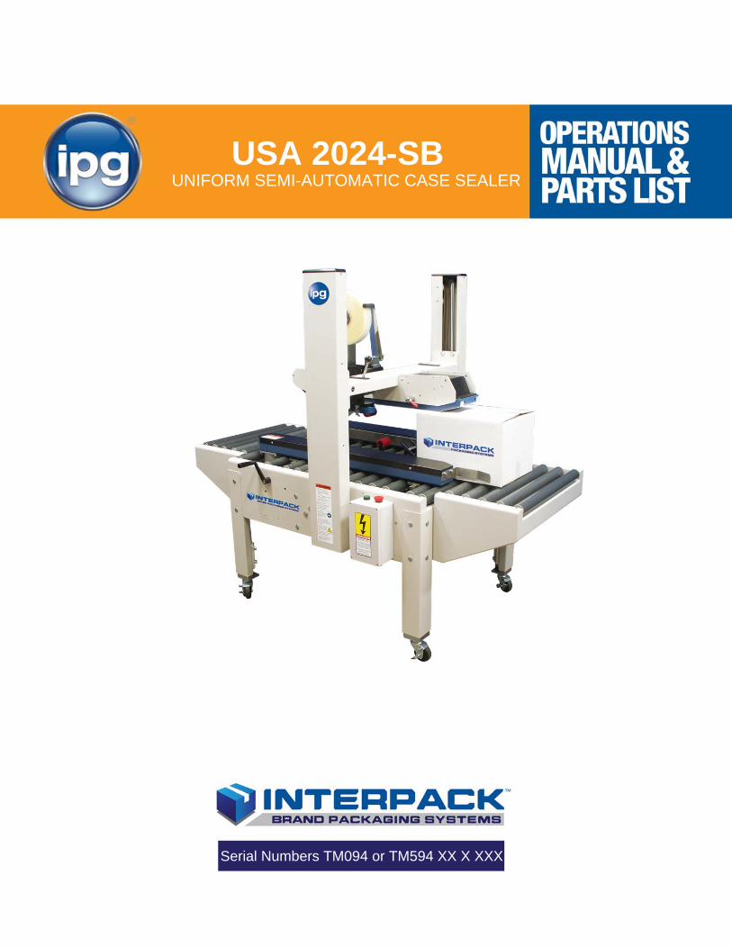
USA 2024-SB
Serial Numbers TM094 or TM594 XX X XXX
UNIFORM SEMI-AUTOMATIC CASE SEALER
UM094TW / UM594TW UDM094-04
2
TABLE OF CONTENTS Section 1 Table Of Contents------------------------------------------------- 2
Section 2 Revision Control--------------------------------------------------- 3
Section 2 Technical and Field Assistance------------------------------ 4-5
Section 3 Warranty-------------------------------------------------------------- 6
Section 4 Description of the USA 2024-SB Case Sealer----------- 7
Section 5 Important Safeguards-------------------------------------------- 8-15
Section 6 Specifications------------------------------------------------------- 16-20
Section 7 Set-Up Procedures------------------------------------------------ 21-34
Section 8 Operating Instructions------------------------------------------- 35-40
Section 8 Troubleshooting--------------------------------------------------- 41-43
Section 9 Recommended Spare Parts List------------------------------ 44
Section 10 Preventive Maintenance----------------------------------------- 45-48
Section 11 Machine Maintenance & Adjustment------------------------ 49-51
Section 12 Optional Equipment----------------------------------------------- 52
Section 13 Schematic Diagrams---------------------------------------------- 53
Section 14 Appendix A-Illustrations And Parts Lists------------------ 54

UM094TW / UM594TW UDM094-04
3
REVISION CONTROL
REVISION CONTROL REV00 Initial Release
REV01 Modified Index
REV02 Final Release
REV03 Updated
REV04 Updated
UM094TW / UM594TW UDM094-04
4
TECHNICAL ASSISTANCE
Technical Support
This is the Interpack Model USA 2024-SB Uniform Semi-Automatic Case Sealer you ordered. It has been set up and tested in our factory with Intertape manufactured pressure sensitive tapes. If any problems occur when setting up or operating this equipment, please contact the authorized distributor from where you purchased this item. Should you need to contact Interpack Technical Support, please have the Case Sealer model number and serial number available. This information can be found on the nameplate of the side panel of the machine. Interpack Technical Support is available during normal business hours (Eastern Time). PHONE 813-621-8410 x101 If you have a technical question that does not require an immediate response, you may contact Interpack by fax. FAX 813-621-8449
Replacement Parts
Order parts by item number, part name and quantity required. Replacement parts are available from your Authorized Interpack Distributor exclusively. Should you require assistance selecting the correct part, you may call: Intertape Polymer Group Interpack Machinery 9940 Currie Davis Drive, Suite B23 Tampa, FL, 33619 Tel: 1-800-474-8273 Option 3 Fax: 1-800-462-1293 MODEL: SERIAL NUMBER: DISTRIBUTOR PURCHASED FROM: DATE OF PURCHASE:

UM094TW / UM594TW UDM094-04
5
FIELD SERVICE ASSISTANCE
This machine is designed to provide years of trouble free operation. If any problems arise with this machine during the normal course of operation, your properly trained and qualified internal service personnel should be able to repair any issues after consulting the Trouble Shooting section of this manual. However, after consulting the Trouble Shooting Section of this manual, you cannot remedy the problem, customer paid service support is available from your Authorized Interpack Distributor.
UM094TW / UM594TW UDM094-04
6
WARRANTY
EQUIPMENT WARRANTY AND LIMITED REMEDY: The following warranty is made in lieu of all other warranties, express or implied, including, but not limited to, the implied warranty of merchantability, the implied warranty of fitness for a particular purpose, and any implied warranty arising out of a course of dealing, a custom or usage of trade: Intertape sells its Interpack Tape Heads, Case Tapers and Case Erectors with the following warranties:
1. The HSD 2000 Tape Heads' knife blades, springs and wipe down rollers will be free from all defects for a period of ninety (90) days.
2. All other HSD 2000 Tape Head parts will be free from all defects for one (1) year after delivery. 3. Water Activated Tapers’ blades and brushes will be free from defects for ninety (90) days after
delivery 4. Drive Belts will be free from defects for ninety (90) days after delivery 5. The Gear Motors will be free from defects for one (1) year after delivery. 6. All other components for Case Tapers and Case Erectors will be free from defects for one (1)
year after delivery. If any part is proven defective within its warranty period, then the exclusive remedy and Intertape's and the seller's sole obligation shall be, at Intertype’s option, to repair or replace the part, provided the defective part is returned immediately to Intertape's factory or an authorized service station designated by Intertape. A part will be presumed to have become defective after its warranty period unless the part is received or Intertape is notified of the problem no later than five (5) calendar days after the warranty period. If Intertape is unable to repair or replace the part within a reasonable time, then Intertape, at its option, will replace the equipment or refund the purchase price. Intertape shall have no obligation to install the repaired or replacement part. Intertape shall have no obligation to provide or pay for the labor required to install the repaired or replacement part. Intertape shall have no obligation to repair or replace (1) those parts failing due to: operator misuse, carelessness, or due to any accidental cause other than equipment failure, or (2) parts
1. Failure or damage is due to misapplication, lack of proper maintenance, abuse, improper installation or abnormal conditions such as temperature, moisture, dirt or corrosive matter, etc.
2. Failure due to inadequate cleaning, improper operating environment, improper utilities or operator error.
3. Failure due to operations above the rated capacities, or in any other improper manner, either intentional or otherwise.
4. Failure is due to equipment, which has been altered by anyone other than an authorized representative of Intertape Polymer Group.
5. Failure is due to an attempt by the purchaser to correct alleged defective equipment. In this event the purchaser is responsible for all expenses incurred.
LIMITATION OF LIABILITY: Intertape and seller shall not be liable for direct, indirect, special, incidental or consequential damages based upon breach of warranty, breach of contract, negligence, strict liability or any other legal theory. The foregoing Equipment Warranty and Limited Remedy and Limitation of Liability may be changed only by written agreement signed by authorized officers of Intertape and seller.
UM094TW / UM594TW UDM094-04
7
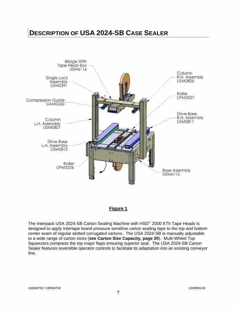
DESCRIPTION OF USA 2024-SB CASE SEALER
Figure 1
The Interpack USA 2024-SB Carton Sealing Machine with HSD 2000 ETII Tape Heads is designed to apply Intertape brand pressure sensitive carton sealing tape to the top and bottom center seam of regular slotted corrugated cartons. The USA 2024-SB is manually adjustable to a wide range of carton sizes (see Carton Size Capacity, page 20). Multi-Wheel Top Squeezers compress the top major flaps ensuring superior seal. The USA 2024-SB Carton Sealer features reversible operator controls to facilitate its adaptation into an existing conveyor line.
UM094TW / UM594TW UDM094-04
8
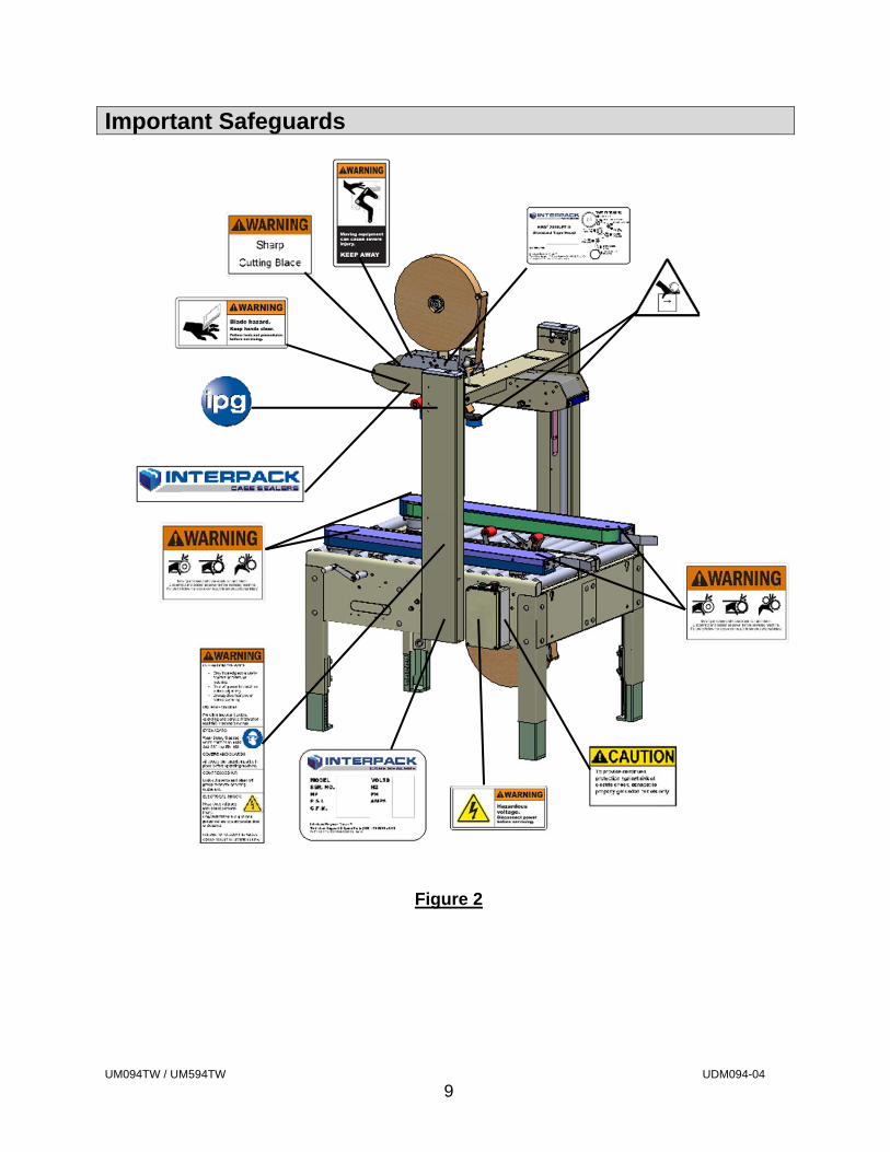
Important Safeguards
There are a number of safety labels used on Interpack Carton Sealers. These labels are placed at different locations (refer to Figure 2) on the machine to warn operators and service personnel of possible dangers. Please read the labels on the machine and the following safety precautions before using the machine.
Read this manual for other important safety operating and service information.
Only trained personnel are to operate machine.
Only fully qualified technicians are to service this machine.
Wear safety glasses.
Shut off power to machine before adjusting machine or loading & threading Tape Heads.
Disconnect electrical power and compressed air (where applicable) before servicing.
Follow Lock Out / Tag Out Procedures BEFORE servicing any machinery.
All covers and guards must be in place before operating.
Stay clear of moving parts which can shear and cut.
Never operate the Tape Heads with the Knife Guard removed.
Note: Should any of the safety labels placed on the Case Sealer be damaged or destroyed, replacements are available through your distributor.
UM094TW / UM594TW UDM094-04
9
Important Safeguards
Figure 2
UM094TW / UM594TW UDM094-04
10
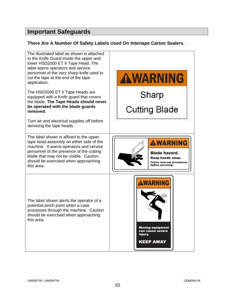
Important Safeguards There Are A Number Of Safety Labels Used On Intertape Carton Sealers. The illustrated label as shown is attached to the Knife Guard inside the upper and lower HSD2000 ET II Tape Head. The label warns operators and service personnel of the very sharp knife used to cut the tape at the end of the tape application. The HSD2000 ET II Tape Heads are equipped with a Knife guard that covers the blade. The Tape Heads should never be operated with the blade guards removed. Turn air and electrical supplies off before servicing the tape heads.
The label shown is affixed to the upper tape head assembly on either side of the machine. It warns operators and service personnel of the presence of the cutting blade that may not be visible. Caution should be exercised when approaching this area
The label shown alerts the operator of a potential pinch point when a case processes through the machine. Caution should be exercised when approaching this area
UM094TW / UM594TW UDM094-04
11
Important Safeguards
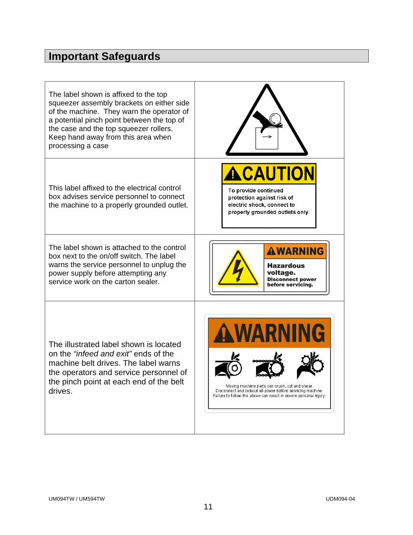
The label shown is affixed to the top squeezer assembly brackets on either side of the machine. They warn the operator of a potential pinch point between the top of the case and the top squeezer rollers. Keep hand away from this area when processing a case
This label affixed to the electrical control box advises service personnel to connect the machine to a properly grounded outlet.
The label shown is attached to the control box next to the on/off switch. The label warns the service personnel to unplug the power supply before attempting any service work on the carton sealer.
The illustrated label shown is located on the “infeed and exit” ends of the machine belt drives. The label warns the operators and service personnel of the pinch point at each end of the belt drives.
UM094TW / UM594TW UDM094-04
12
Important Safeguards
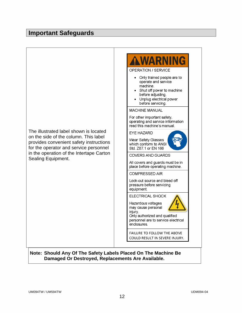
The illustrated label shown is located on the side of the column. This label provides convenient safety instructions for the operator and service personnel in the operation of the Intertape Carton Sealing Equipment.
Note: Should Any Of The Safety Labels Placed On The Machine Be Damaged Or Destroyed, Replacements Are Available.
UM094TW / UM594TW UDM094-04
13
Important Safeguards
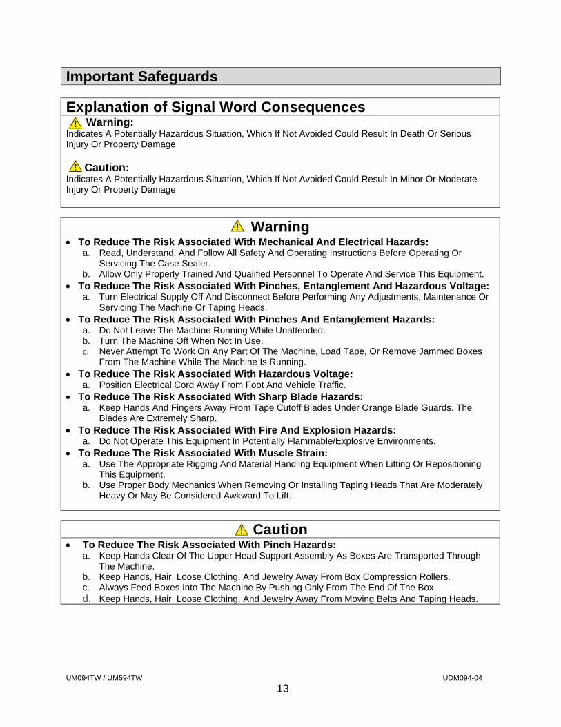
Explanation of Signal Word Consequences Warning: Indicates A Potentially Hazardous Situation, Which If Not Avoided Could Result In Death Or Serious Injury Or Property Damage Caution: Indicates A Potentially Hazardous Situation, Which If Not Avoided Could Result In Minor Or Moderate Injury Or Property Damage
Warning
To Reduce The Risk Associated With Mechanical And Electrical Hazards: a. Read, Understand, And Follow All Safety And Operating Instructions Before Operating Or
Servicing The Case Sealer. b. Allow Only Properly Trained And Qualified Personnel To Operate And Service This Equipment.
To Reduce The Risk Associated With Pinches, Entanglement And Hazardous Voltage: a. Turn Electrical Supply Off And Disconnect Before Performing Any Adjustments, Maintenance Or
Servicing The Machine Or Taping Heads. To Reduce The Risk Associated With Pinches And Entanglement Hazards:
a. Do Not Leave The Machine Running While Unattended. b. Turn The Machine Off When Not In Use. c. Never Attempt To Work On Any Part Of The Machine, Load Tape, Or Remove Jammed Boxes
From The Machine While The Machine Is Running. To Reduce The Risk Associated With Hazardous Voltage:
a. Position Electrical Cord Away From Foot And Vehicle Traffic. To Reduce The Risk Associated With Sharp Blade Hazards:
a. Keep Hands And Fingers Away From Tape Cutoff Blades Under Orange Blade Guards. The Blades Are Extremely Sharp.
To Reduce The Risk Associated With Fire And Explosion Hazards: a. Do Not Operate This Equipment In Potentially Flammable/Explosive Environments.
To Reduce The Risk Associated With Muscle Strain: a. Use The Appropriate Rigging And Material Handling Equipment When Lifting Or Repositioning
This Equipment. b. Use Proper Body Mechanics When Removing Or Installing Taping Heads That Are Moderately
Heavy Or May Be Considered Awkward To Lift.
Caution
To Reduce The Risk Associated With Pinch Hazards: a. Keep Hands Clear Of The Upper Head Support Assembly As Boxes Are Transported Through
The Machine. b. Keep Hands, Hair, Loose Clothing, And Jewelry Away From Box Compression Rollers. c. Always Feed Boxes Into The Machine By Pushing Only From The End Of The Box. d. Keep Hands, Hair, Loose Clothing, And Jewelry Away From Moving Belts And Taping Heads.
UM094TW / UM594TW UDM094-04
14
Important Safeguards
Warning To Reduce The Risk Associated With Mechanical And Electrical Hazards:
a. Allow Only Properly Trained And Qualified Personnel To Operate And Service This Equipment.
Operator Skill Level Descriptions Skill “A”: Machine Operator This Operator Is Trained To Use The Machine With The Machine Controls, To Feed Cases Into The Machine, Make Adjustment For Different Case Sizes, To Change The Tape And To Start, Stop, And To Re-Start Production
Important: The Area Supervisor Must Ensure That The Operator Has Been Properly Trained On All Machine Functions Before Operating The Machine.
Skill “B” Mechanical Maintenance Technician This Technician Is Trained To Use The Machine As The Machine Operator And In Addition Is Able To Work With The Safety Protection Disconnected, To Check And Adjust Mechanical Components, To Perform Maintenance Operations And Repair The Machine. He Is Not Allowed To Work On Live Electrical Components Skill “C” Electrical Maintenance Technician This Technician Is Trained To Use The Machine As The Machine Operator And In Addition Is Able To Work With The Safety Protection Disconnected, To Check And Adjust Mechanical Components, To Perform Maintenance Operations And Repair The Machine. He Is Allowed To Work On Live Electrical Panels, Terminal Blocks And Control Equipment. Skill “D” Manufacturers Technician Skilled Technician Sent By The Manufacturer Or Its Agent To Perform Complex Repairs Or Modifications, When Agreed With The Customer
UM094TW / UM594TW UDM094-04
15
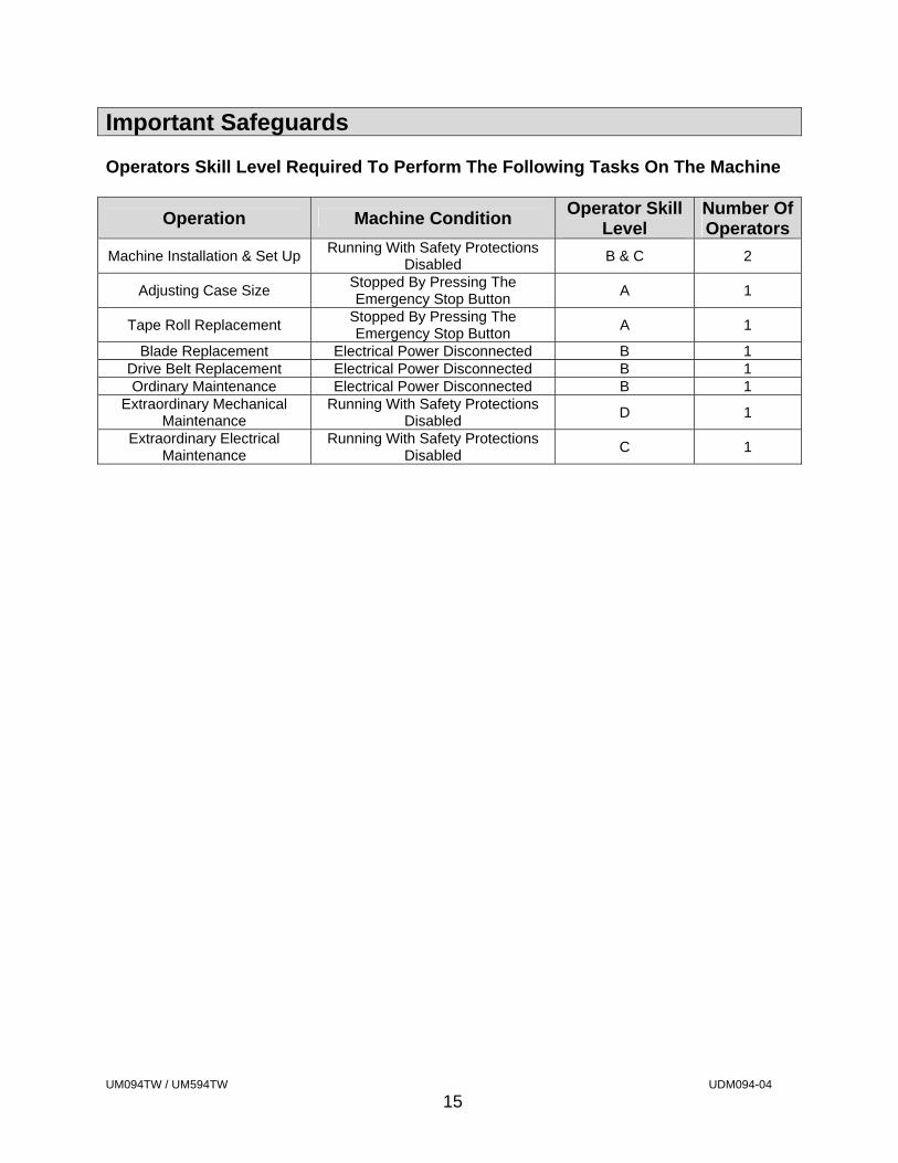
Important Safeguards Operators Skill Level Required To Perform The Following Tasks On The Machine
Operation Machine Condition Operator Skill
Level Number Of Operators
Machine Installation & Set Up Running With Safety Protections
Disabled B & C 2
Adjusting Case Size Stopped By Pressing The Emergency Stop Button
A 1
Tape Roll Replacement Stopped By Pressing The Emergency Stop Button
A 1
Blade Replacement Electrical Power Disconnected B 1 Drive Belt Replacement Electrical Power Disconnected B 1 Ordinary Maintenance Electrical Power Disconnected B 1
Extraordinary Mechanical Maintenance
Running With Safety Protections Disabled
D 1
Extraordinary Electrical Maintenance
Running With Safety Protections Disabled
C 1

UM094TW / UM594TW UDM094-04
16
SPECIFICATIONS USA 2024-SB Machine Dimensions
Figure-3
Machine Weight: 560 lbs. (254 kg) crated
UM094TW / UM594TW UDM094-04
17
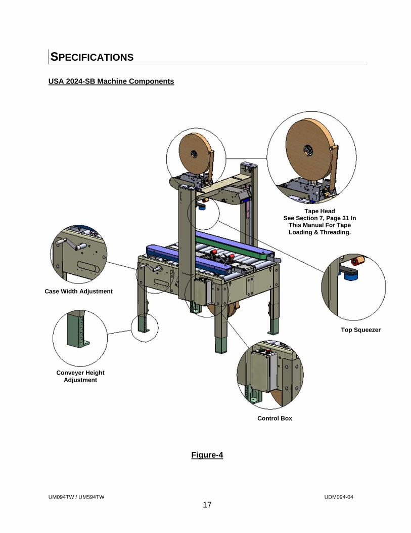
SPECIFICATIONS USA 2024-SB Machine Components
Figure-4
Tape HeadSee Section 7, Page 31 In
This Manual For Tape Loading & Threading.
Conveyer Height Adjustment
Case Width Adjustment
Control Box
Top Squeezer
UM094TW / UM594TW UDM094-04
18
SPECIFICATIONS
1. Operating Conditions
Use in a dry, relatively clean environment at 40° to 105° F (5° to 40° C) with clean dry cartons.
Note: Machine should not be washed down or subjected to conditions causing condensation on components.
2. Power Requirements
Electrical - 115 VAC, 60 HZ, 5.0 A (560 Watts) Compressed Air – N/A This machine comes standard with two gear motors, one on each drive base and an electrical box. The electrical box contains a Start switch, the Emergency Stop switch, and a starting relay with a thermal over load. An eleven foot (11’) standard three conductor power cord with plug is provided for 115V, 60HZ, 15 Amp service. The receptacle providing this service must be properly grounded.
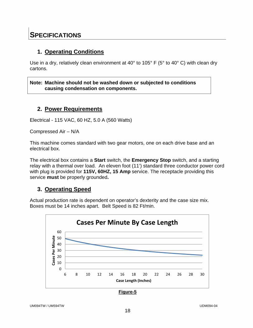
3. Operating Speed
Actual production rate is dependent on operator’s dexterity and the case size mix. Boxes must be 14 inches apart. Belt Speed is 82 Ft/min.
Figure-5
0
10
20
30
40
50
60
6 8 10 12 14 16 18 20 22 24 26 28 30
Cases Per Minute
Case Length (Inches)
Cases Per Minute By Case Length
UM094TW / UM594TW UDM094-04
19
4. Tape Specifications
Use Intertape Brand Pressure Sensitive Carton Sealing Tape. The machine can accommodate 2” (48mm) or 3” (72mm) wide tape, depending on tape heads supplied. A maximum tape roll diameter of 16” (406 mm) on a 3” (76 mm) diameter core can be installed on the tape head. (Accommodates all Intertape brand film tape machine roll lengths). The standard Tape Leg Length of 2.25 inches (57.2 mm) is factory set. The standard tape leg length may vary up to ¼” (6mm) based on tape tension and line speed. The standard tape leg length is adjustable +/- ¼. Refer to the tape head manual for adjustment of tape leg length.
Note: For Further Specifications On The Tape Heads, Consult The Tape Head Manual For Your Specific Tape Head.
UM094TW / UM594TW UDM094-04
20
5. Carton Specifications
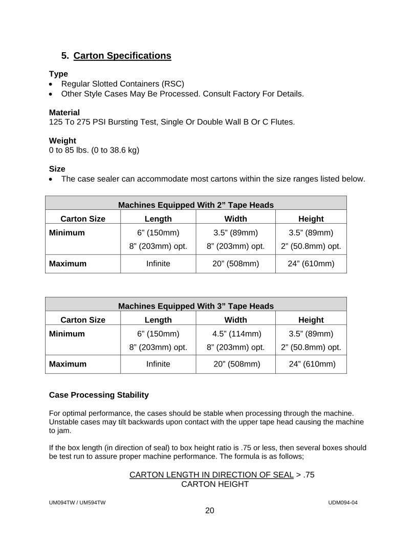
Type Regular Slotted Containers (RSC) Other Style Cases May Be Processed. Consult Factory For Details. Material 125 To 275 PSI Bursting Test, Single Or Double Wall B Or C Flutes. Weight 0 to 85 lbs. (0 to 38.6 kg) Size The case sealer can accommodate most cartons within the size ranges listed below.
Case Processing Stability For optimal performance, the cases should be stable when processing through the machine. Unstable cases may tilt backwards upon contact with the upper tape head causing the machine to jam. If the box length (in direction of seal) to box height ratio is .75 or less, then several boxes should be test run to assure proper machine performance. The formula is as follows;
CARTON LENGTH IN DIRECTION OF SEAL > .75 CARTON HEIGHT
Machines Equipped With 2” Tape Heads
Carton Size Length Width Height
Minimum 6” (150mm)
8” (203mm) opt.
3.5” (89mm)
8” (203mm) opt.
3.5” (89mm)
2” (50.8mm) opt.
Maximum Infinite 20” (508mm) 24” (610mm)
Machines Equipped With 3” Tape Heads
Carton Size Length Width Height
Minimum 6” (150mm)
8” (203mm) opt.
4.5” (114mm)
8” (203mm) opt.
3.5” (89mm)
2” (50.8mm) opt.
Maximum Infinite 20” (508mm) 24” (610mm)
UM094TW / UM594TW UDM094-04
21
SET-UP PROCEDURES
1. Receiving and Handling
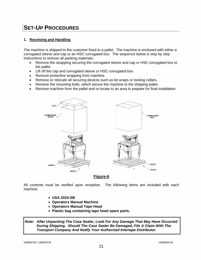
The machine is shipped to the customer fixed to a pallet. The machine is enclosed with either a corrugated sleeve and cap or an HSC corrugated box. The sequence below is step by step instructions to remove all packing materials.
Remove the strapping securing the corrugated sleeve and cap or HSC corrugated box to the pallet.
Lift off the cap and corrugated sleeve or HSC corrugated box. Remove protective wrapping from machine. Remove or relocate all securing devices such as tie wraps or locking collars. Remove the mounting bolts, which secure the machine to the shipping pallet. Remove machine from the pallet and re-locate to an area to prepare for final installation.
Figure-6
All contents must be verified upon reception. The following items are included with each machine.
USA 2024-SB Operators Manual Machine Operators Manual Tape Head Plastic bag containing tape head spare parts.
Note: After Unpacking The Case Sealer, Look For Any Damage That May Have Occurred During Shipping. Should The Case Sealer Be Damaged, File A Claim With The Transport Company And Notify Your Authorized Intertape Distributor.
UM094TW / UM594TW UDM094-04
22
SET-UP PROCEDURES
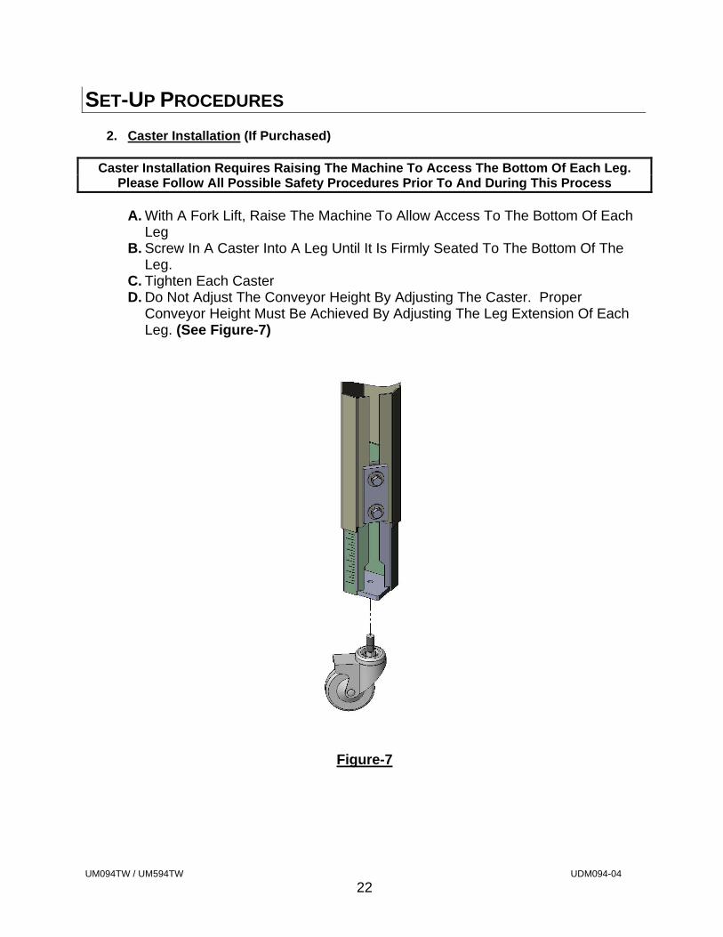
2. Caster Installation (If Purchased)
Caster Installation Requires Raising The Machine To Access The Bottom Of Each Leg. Please Follow All Possible Safety Procedures Prior To And During This Process
A. With A Fork Lift, Raise The Machine To Allow Access To The Bottom Of Each Leg
B. Screw In A Caster Into A Leg Until It Is Firmly Seated To The Bottom Of The Leg.
C. Tighten Each Caster D. Do Not Adjust The Conveyor Height By Adjusting The Caster. Proper
Conveyor Height Must Be Achieved By Adjusting The Leg Extension Of Each Leg. (See Figure-7)
Figure-7
UM094TW / UM594TW UDM094-04
23
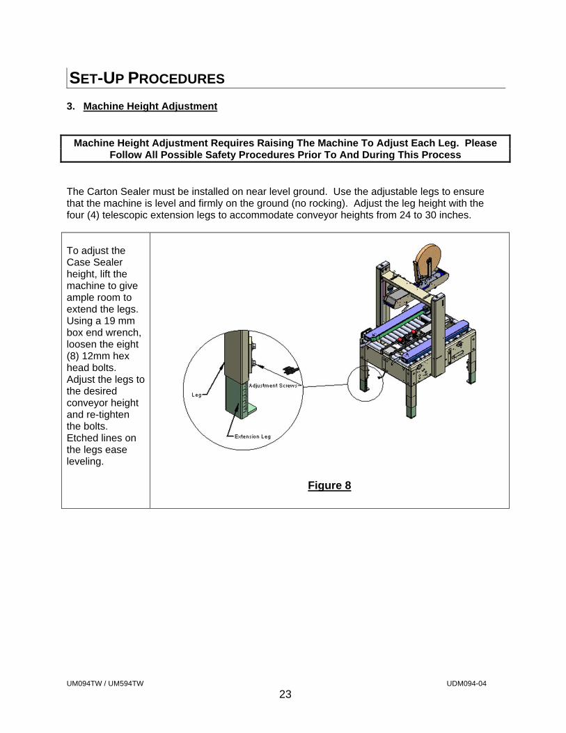
SET-UP PROCEDURES 3. Machine Height Adjustment
Machine Height Adjustment Requires Raising The Machine To Adjust Each Leg. Please
Follow All Possible Safety Procedures Prior To And During This Process
The Carton Sealer must be installed on near level ground. Use the adjustable legs to ensure that the machine is level and firmly on the ground (no rocking). Adjust the leg height with the four (4) telescopic extension legs to accommodate conveyor heights from 24 to 30 inches. To adjust the Case Sealer height, lift the machine to give ample room to extend the legs. Using a 19 mm box end wrench, loosen the eight (8) 12mm hex head bolts. Adjust the legs to the desired conveyor height and re-tighten the bolts. Etched lines on the legs ease leveling.
Figure 8
UM094TW / UM594TW UDM094-04
24
SET-UP PROCEDURES
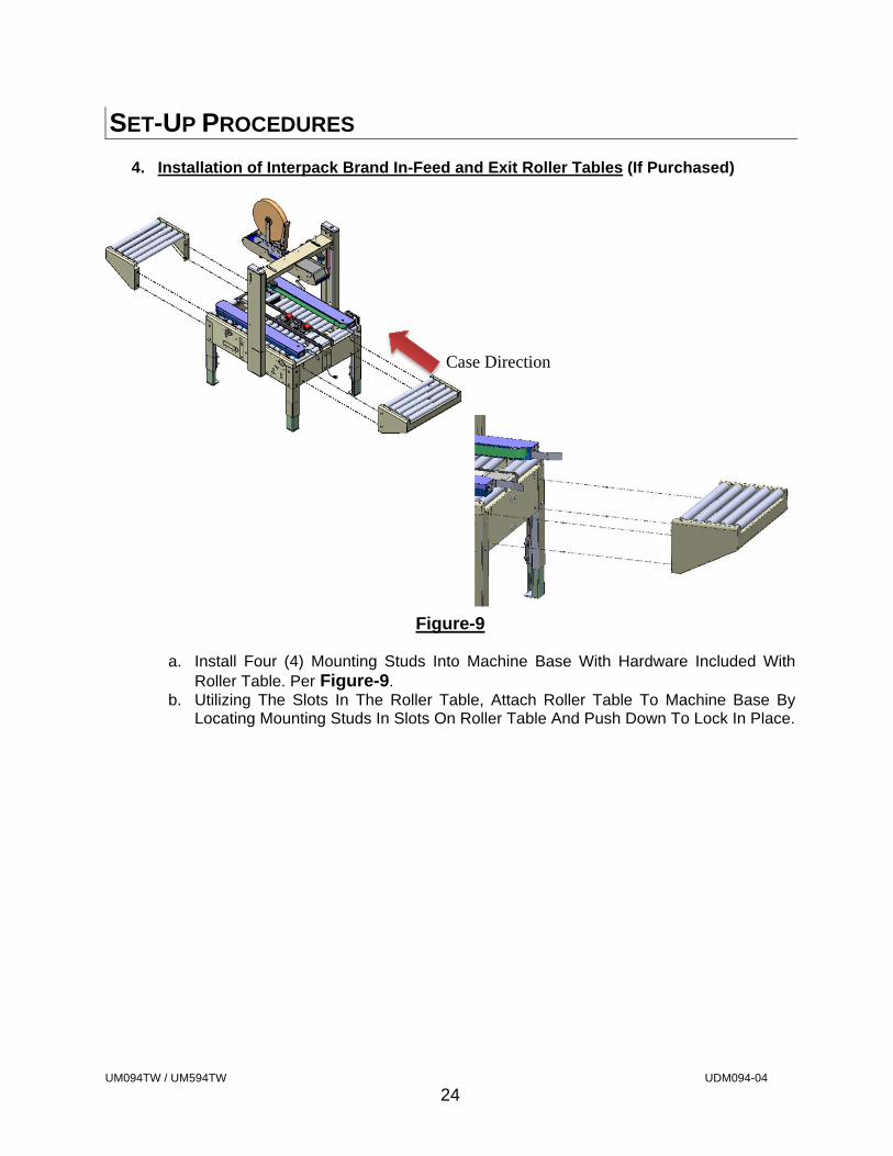
4. Installation of Interpack Brand In-Feed and Exit Roller Tables (If Purchased)
Figure-9
a. Install Four (4) Mounting Studs Into Machine Base With Hardware Included With
Roller Table. Per Figure-9. b. Utilizing The Slots In The Roller Table, Attach Roller Table To Machine Base By
Locating Mounting Studs In Slots On Roller Table And Push Down To Lock In Place.
Case Direction
UM094TW / UM594TW UDM094-04
25
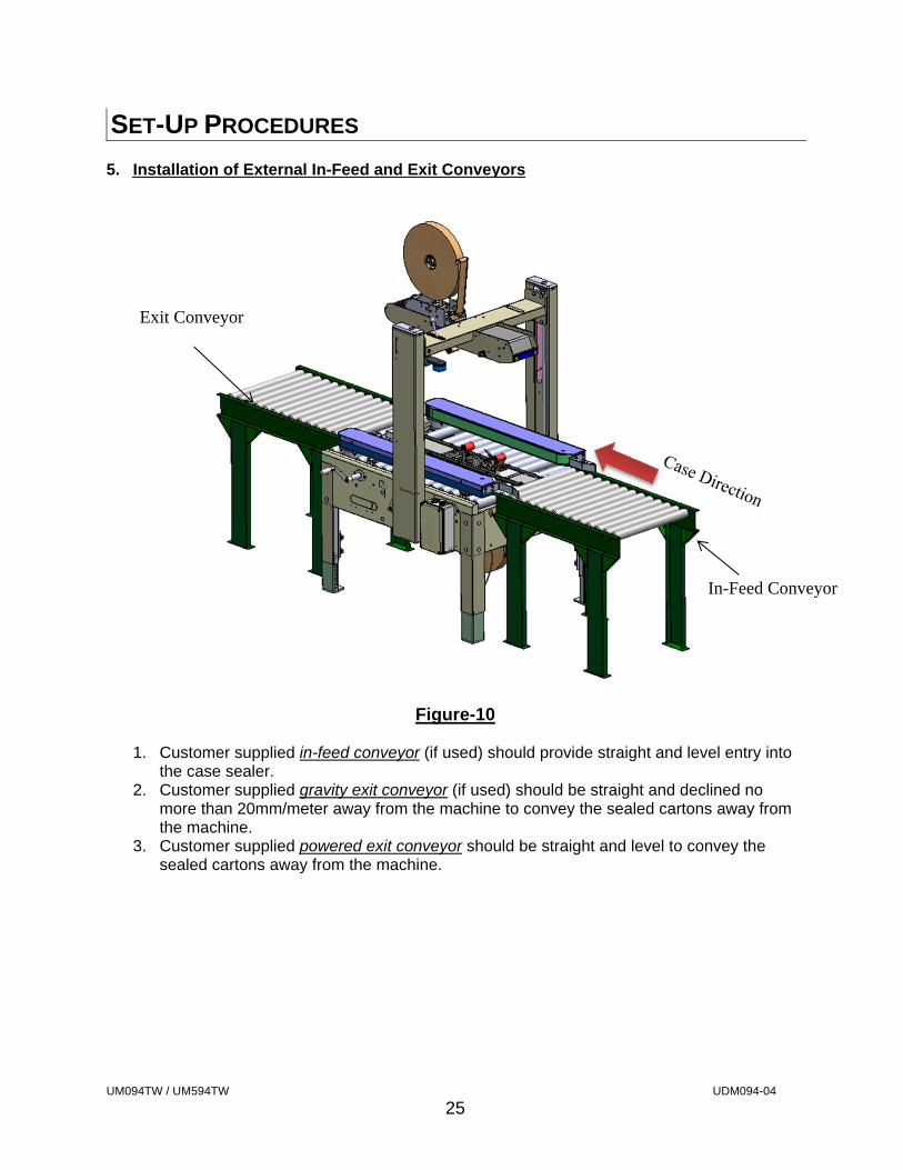
SET-UP PROCEDURES 5. Installation of External In-Feed and Exit Conveyors
Figure-10
1. Customer supplied in-feed conveyor (if used) should provide straight and level entry into
the case sealer. 2. Customer supplied gravity exit conveyor (if used) should be straight and declined no
more than 20mm/meter away from the machine to convey the sealed cartons away from the machine.
3. Customer supplied powered exit conveyor should be straight and level to convey the sealed cartons away from the machine.
Exit Conveyor
In-Feed Conveyor
UM094TW / UM594TW UDM094-04
26
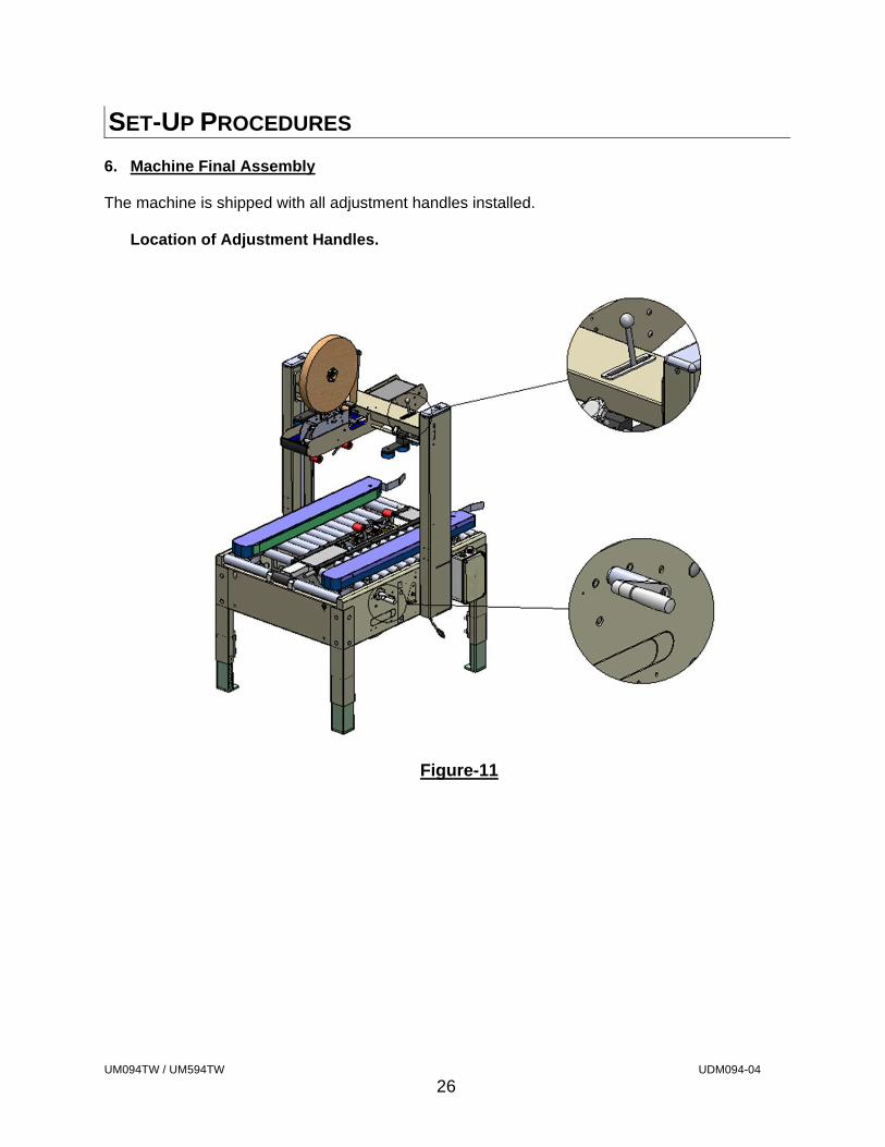
SET-UP PROCEDURES 6. Machine Final Assembly The machine is shipped with all adjustment handles installed.
Location of Adjustment Handles.
Figure-11
UM094TW / UM594TW UDM094-04
27
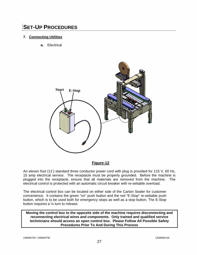
SET-UP PROCEDURES 7. Connecting Utilities
a. Electrical
Figure-12 An eleven foot (11’) standard three conductor power cord with plug is provided for 115 V, 60 Hz, 15 amp electrical service. The receptacle must be properly grounded. Before the machine is plugged into the receptacle, ensure that all materials are removed from the machine. The electrical control is protected with an automatic circuit breaker with re-settable overload. The electrical control box can be located on either side of the Carton Sealer for customer convenience. It contains the green “on” push button and the red “E-Stop” re-settable push button, which is to be used both for emergency stops as well as a stop button, The E-Stop button requires a ¼ turn to release.
Moving the control box to the opposite side of the machine requires disconnecting and reconnecting electrical wires and components. Only trained and qualified service technicians should access an open control box. Please Follow All Possible Safety
Procedures Prior To And During This Process
Start E-Stop
UM094TW / UM594TW UDM094-04
28
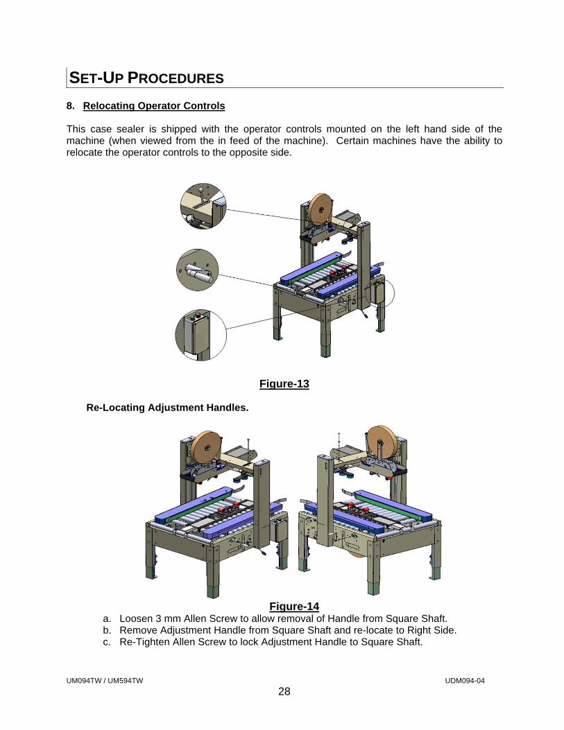
SET-UP PROCEDURES 8. Relocating Operator Controls This case sealer is shipped with the operator controls mounted on the left hand side of the machine (when viewed from the in feed of the machine). Certain machines have the ability to relocate the operator controls to the opposite side.
Figure-13
Re-Locating Adjustment Handles.
Figure-14
a. Loosen 3 mm Allen Screw to allow removal of Handle from Square Shaft. b. Remove Adjustment Handle from Square Shaft and re-locate to Right Side. c. Re-Tighten Allen Screw to lock Adjustment Handle to Square Shaft.

UM094TW / UM594TW UDM094-04
29
SET-UP PROCEDURES Re-Locating Electrical Control Box
Figure-15
Moving the control box to the opposite side of the machine requires disconnecting and reconnecting electrical wires and components. Only trained and qualified service technicians should access an open control box. Please Follow All Possible Safety
Procedures Prior To And During This Process
a. Disconnect machine from electrical supply. b. Remove Cover. c. Note the position of the wires to be disconnected to allow for re-location. d. Disconnect wires from motor starter. e. Disconnect ground Wires. f. Remove Lock Nut from Strain Relief (2) inside Electrical Control Box. g. Remove Strain Relief (2) and wires from Control Box. h. Remove Control Box and Re-Locate to Opposite Side. i. Route wires (3) to opposite side of machine.
i. Remove wire ties holding wires under machine. ii. Re-locate wires to re-positioned control box. iii. Install new wire ties to secure wires to machine base.
j. Insert Strain Reliefs (2) and wires into Control Box. k. Re-Install Strain Relief Lock Nuts (2). l. Re-Connect wires to Motor Starter. m. Re-Connect ground Wires. n. Re-Install Cover.
Start E-Stop
UM094TW / UM594TW UDM094-04
30
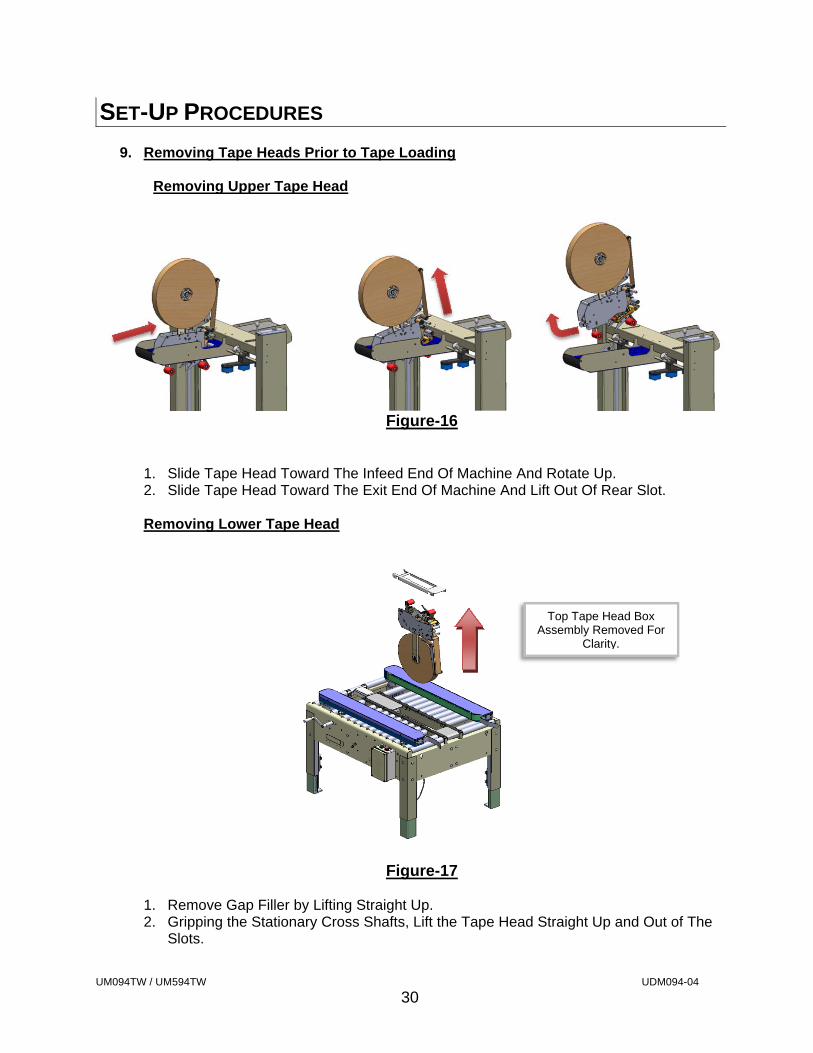
SET-UP PROCEDURES 9. Removing Tape Heads Prior to Tape Loading
Removing Upper Tape Head
Figure-16
1. Slide Tape Head Toward The Infeed End Of Machine And Rotate Up. 2. Slide Tape Head Toward The Exit End Of Machine And Lift Out Of Rear Slot.
Removing Lower Tape Head
Figure-17
1. Remove Gap Filler by Lifting Straight Up. 2. Gripping the Stationary Cross Shafts, Lift the Tape Head Straight Up and Out of The
Slots.
Top Tape Head Box Assembly Removed For
Clarity.
UM094TW / UM594TW UDM094-04
31
SET-UP PROCEDURES
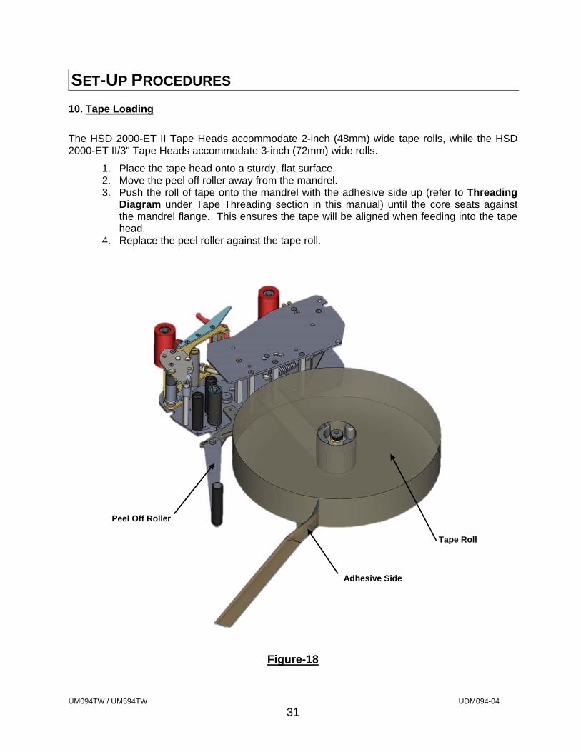
10. Tape Loading
The HSD 2000-ET II Tape Heads accommodate 2-inch (48mm) wide tape rolls, while the HSD 2000-ET II/3" Tape Heads accommodate 3-inch (72mm) wide rolls.
1. Place the tape head onto a sturdy, flat surface. 2. Move the peel off roller away from the mandrel. 3. Push the roll of tape onto the mandrel with the adhesive side up (refer to Threading
Diagram under Tape Threading section in this manual) until the core seats against the mandrel flange. This ensures the tape will be aligned when feeding into the tape head.
4. Replace the peel roller against the tape roll.
Figure-18
Adhesive Side
Peel Off Roller
Tape Roll
UM094TW / UM594TW UDM094-04
32
SET-UP PROCEDURES
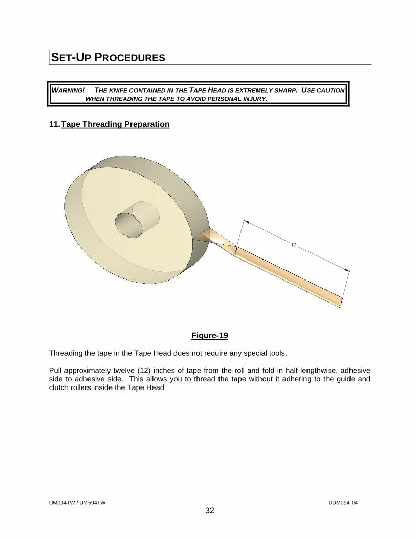
WARNING! THE KNIFE CONTAINED IN THE TAPE HEAD IS EXTREMELY SHARP. USE CAUTION
WHEN THREADING THE TAPE TO AVOID PERSONAL INJURY.
11. Tape Threading Preparation
Figure-19
Threading the tape in the Tape Head does not require any special tools. Pull approximately twelve (12) inches of tape from the roll and fold in half lengthwise, adhesive side to adhesive side. This allows you to thread the tape without it adhering to the guide and clutch rollers inside the Tape Head
12
UM094TW / UM594TW UDM094-04
33
SET-UP PROCEDURES
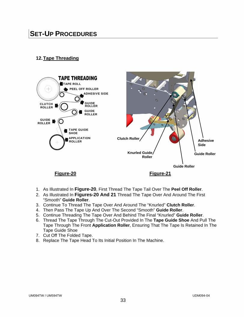
12. Tape Threading
Figure-20 Figure-21
1. As Illustrated In Figure-20, First Thread The Tape Tail Over The Peel Off Roller. 2. As Illustrated In Figures-20 And 21 Thread The Tape Over And Around The First
“Smooth” Guide Roller. 3. Continue To Thread The Tape Over And Around The “Knurled” Clutch Roller. 4. Then Pass The Tape Up And Over The Second “Smooth” Guide Roller. 5. Continue Threading The Tape Over And Behind The Final “Knurled” Guide Roller. 6. Thread The Tape Through The Cut-Out Provided In The Tape Guide Shoe And Pull The
Tape Through The Front Application Roller, Ensuring That The Tape Is Retained In The Tape Guide Shoe
7. Cut Off The Folded Tape. 8. Replace The Tape Head To Its Initial Position In The Machine.
Adhesive Side
Guide Roller
Clutch Roller
ROLLERGUIDE
ROLLERCLUTCH
APPLICATION
TAPE GUIDE
ROLLER
SHOE
GUIDEROLLER
ADHESIVE SIDE
TAPE ROLL
GUIDEROLLER
PEEL OFF ROLLER
Guide Roller Knurled GuideRoller
UM094TW / UM594TW UDM094-04
34
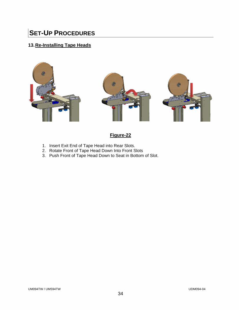
SET-UP PROCEDURES 13. Re-Installing Tape Heads
Figure-22
1. Insert Exit End of Tape Head into Rear Slots. 2. Rotate Front of Tape Head Down Into Front Slots 3. Push Front of Tape Head Down to Seat in Bottom of Slot.
UM094TW / UM594TW UDM094-04
35
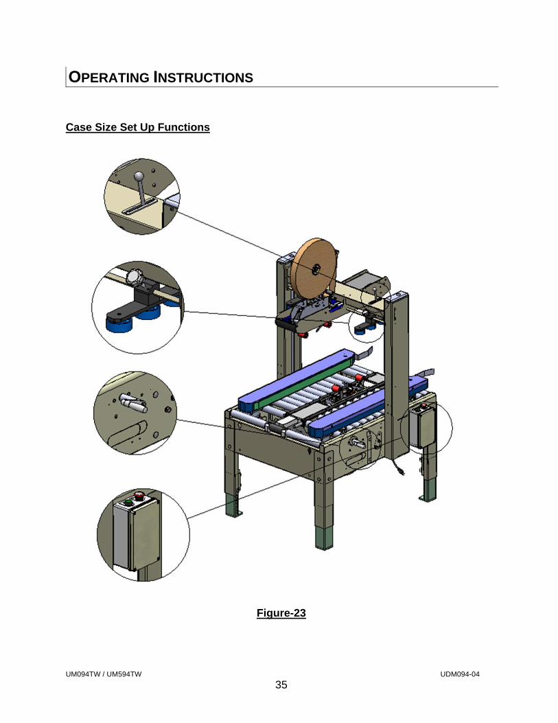
OPERATING INSTRUCTIONS
Case Size Set Up Functions
Figure-23
UM094TW / UM594TW UDM094-04
36
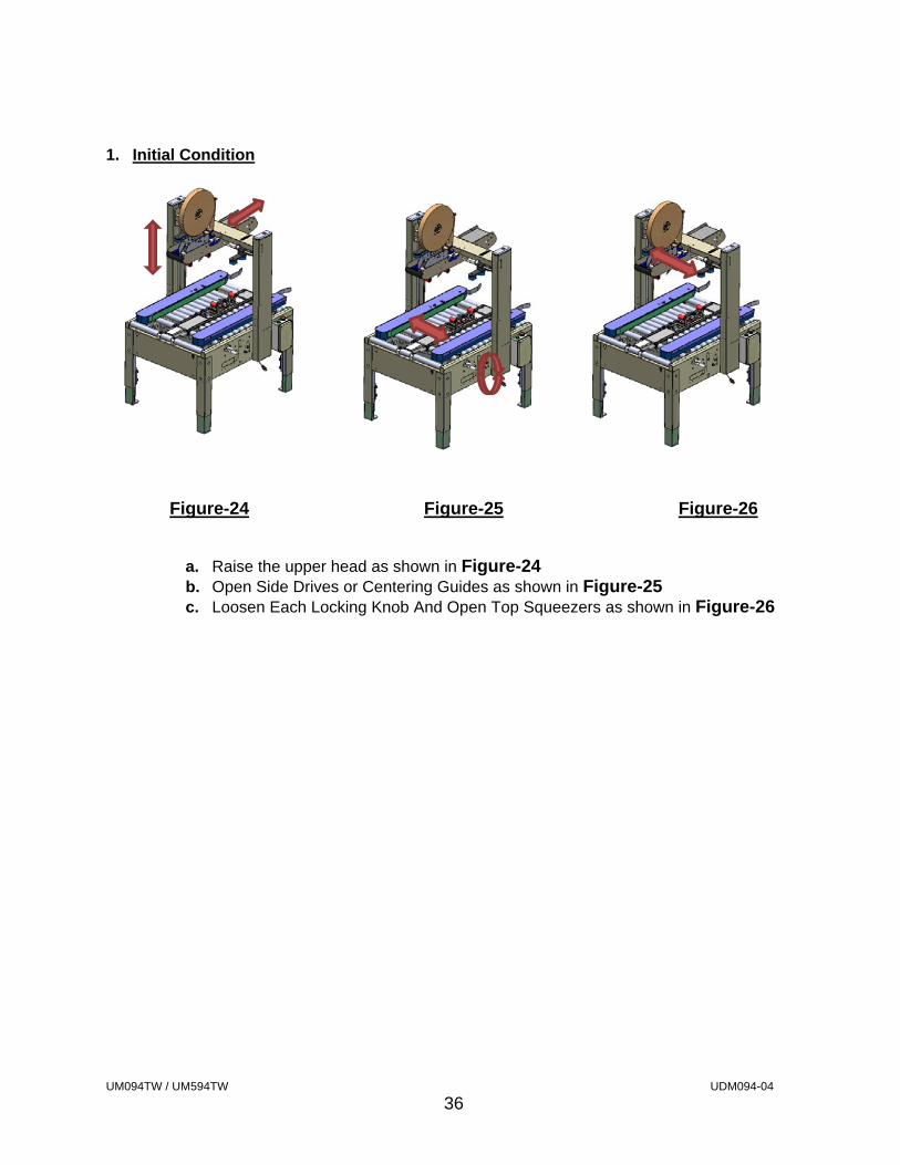
1. Initial Condition
Figure-24 Figure-25 Figure-26
a. Raise the upper head as shown in Figure-24 b. Open Side Drives or Centering Guides as shown in Figure-25 c. Loosen Each Locking Knob And Open Top Squeezers as shown in Figure-26
UM094TW / UM594TW UDM094-04
37
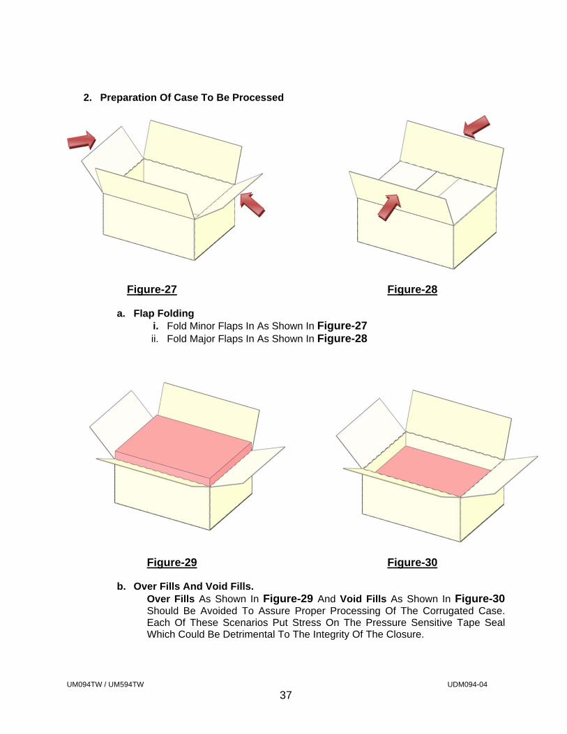
2. Preparation Of Case To Be Processed
Figure-27 Figure-28
a. Flap Folding i. Fold Minor Flaps In As Shown In Figure-27 ii. Fold Major Flaps In As Shown In Figure-28
Figure-29 Figure-30
b. Over Fills And Void Fills. Over Fills As Shown In Figure-29 And Void Fills As Shown In Figure-30 Should Be Avoided To Assure Proper Processing Of The Corrugated Case. Each Of These Scenarios Put Stress On The Pressure Sensitive Tape Seal Which Could Be Detrimental To The Integrity Of The Closure.
UM094TW / UM594TW UDM094-04
38
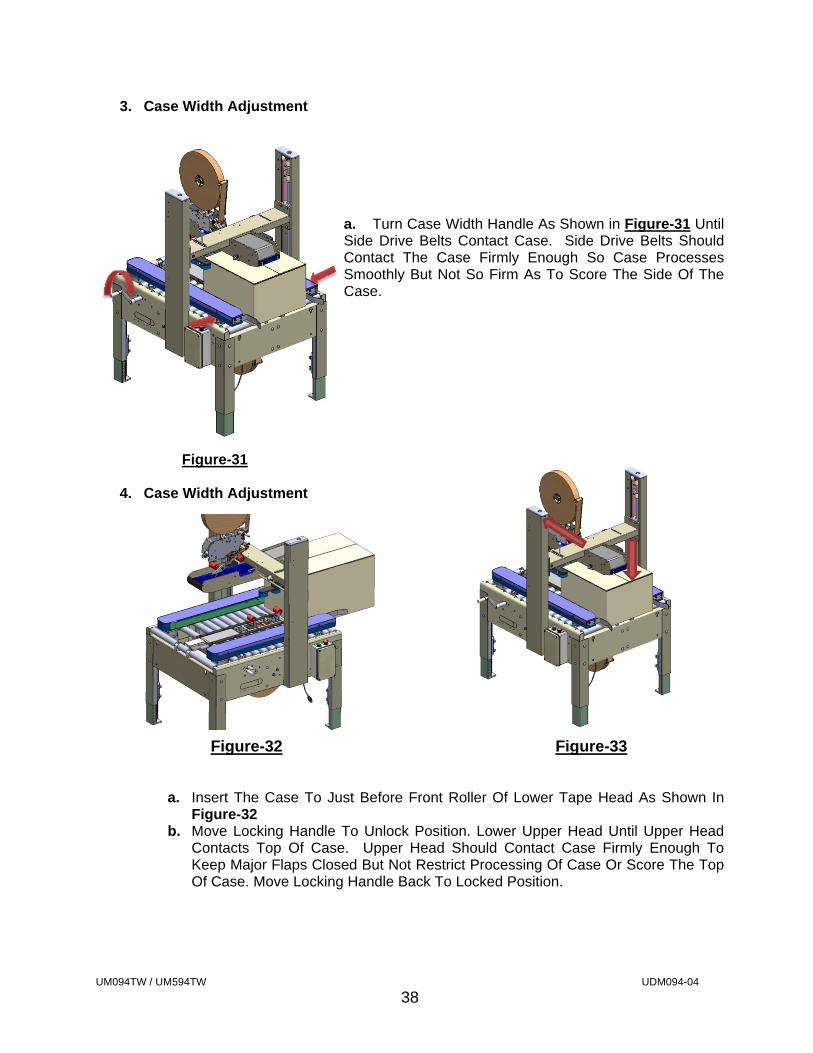
3. Case Width Adjustment
a. Turn Case Width Handle As Shown in Figure-31 Until Side Drive Belts Contact Case. Side Drive Belts Should Contact The Case Firmly Enough So Case Processes Smoothly But Not So Firm As To Score The Side Of The Case.
Figure-31
4. Case Width Adjustment
Figure-32 Figure-33
a. Insert The Case To Just Before Front Roller Of Lower Tape Head As Shown In Figure-32
b. Move Locking Handle To Unlock Position. Lower Upper Head Until Upper Head Contacts Top Of Case. Upper Head Should Contact Case Firmly Enough To Keep Major Flaps Closed But Not Restrict Processing Of Case Or Score The Top Of Case. Move Locking Handle Back To Locked Position.
UM094TW / UM594TW UDM094-04
39
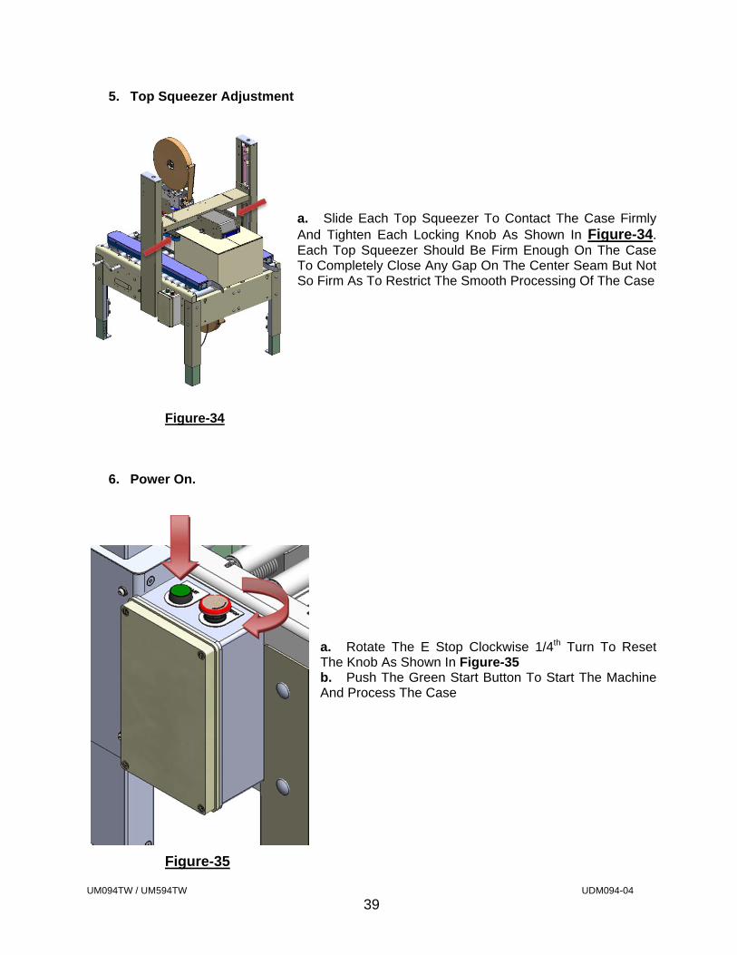
5. Top Squeezer Adjustment
a. Slide Each Top Squeezer To Contact The Case Firmly And Tighten Each Locking Knob As Shown In Figure-34. Each Top Squeezer Should Be Firm Enough On The Case To Completely Close Any Gap On The Center Seam But Not So Firm As To Restrict The Smooth Processing Of The Case
Figure-34
6. Power On.
a. Rotate The E Stop Clockwise 1/4th Turn To Reset The Knob As Shown In Figure-35 b. Push The Green Start Button To Start The Machine And Process The Case
Figure-35

UM094TW / UM594TW UDM094-04
40
7. Review Of Case Processing
Case Should Process Smoothly Through The Machine And Apply The Tape Evenly To Each Top And Bottom Major Flap With A 2 ¼” Tape Leg Applied To Each End Panel. Should The Case Processing Need Correction Please Refer To The Trouble Shooting Section In This Manual
UM094TW / UM594TW UDM094-04
41
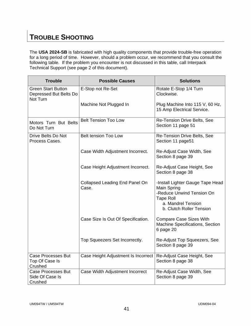
TROUBLE SHOOTING
The USA 2024-SB is fabricated with high quality components that provide trouble-free operation for a long period of time. However, should a problem occur, we recommend that you consult the following table. If the problem you encounter is not discussed in this table, call Interpack Technical Support (see page 2 of this document).
Trouble Possible Causes Solutions
Green Start Button Depressed But Belts Do Not Turn
E-Stop not Re-Set Machine Not Plugged In
Rotate E-Stop 1/4 Turn Clockwise. Plug Machine Into 115 V, 60 Hz, 15 Amp Electrical Service.
Motors Turn But Belts Do Not Turn
Belt Tension Too Low Re-Tension Drive Belts, See Section 11 page 51
Drive Belts Do Not Process Cases.
Belt tension Too Low Case Width Adjustment Incorrect. Case Height Adjustment Incorrect. Collapsed Leading End Panel On Case. Case Size Is Out Of Specification. Top Squeezers Set Incorrectly.
Re-Tension Drive Belts, See Section 11 page51 Re-Adjust Case Width, See Section 8 page 39 Re-Adjust Case Height, See Section 8 page 38 -Install Lighter Gauge Tape Head Main Spring -Reduce Unwind Tension On Tape Roll a. Mandrel Tension b. Clutch Roller Tension Compare Case Sizes With Machine Specifications, Section 6 page 20 Re-Adjust Top Squeezers, See Section 8 page 39
Case Processes But Top Of Case Is Crushed
Case Height Adjustment Is Incorrect Re-Adjust Case Height, See Section 8 page 38
Case Processes But Side Of Case Is Crushed
Case Width Adjustment Incorrect Re-Adjust Case Width, See Section 8 page 39
UM094TW / UM594TW UDM094-04
42
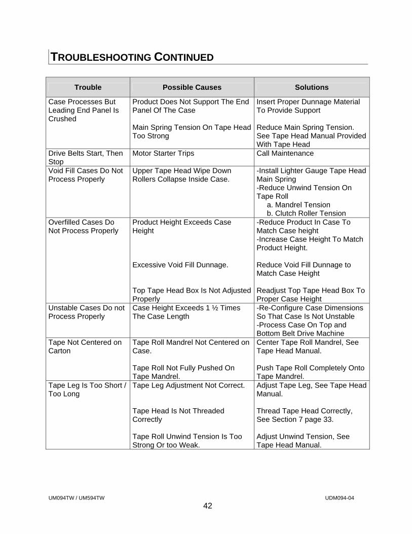
TROUBLESHOOTING CONTINUED
Trouble Possible Causes Solutions
Case Processes But Leading End Panel Is Crushed
Product Does Not Support The End Panel Of The Case Main Spring Tension On Tape Head Too Strong
Insert Proper Dunnage Material To Provide Support Reduce Main Spring Tension. See Tape Head Manual Provided With Tape Head
Drive Belts Start, Then Stop
Motor Starter Trips Call Maintenance
Void Fill Cases Do Not Process Properly
Upper Tape Head Wipe Down Rollers Collapse Inside Case.
-Install Lighter Gauge Tape Head Main Spring -Reduce Unwind Tension On Tape Roll a. Mandrel Tension b. Clutch Roller Tension
Overfilled Cases Do Not Process Properly
Product Height Exceeds Case Height Excessive Void Fill Dunnage. Top Tape Head Box Is Not Adjusted Properly
-Reduce Product In Case To Match Case height -Increase Case Height To Match Product Height. Reduce Void Fill Dunnage to Match Case Height Readjust Top Tape Head Box To Proper Case Height
Unstable Cases Do not Process Properly
Case Height Exceeds 1 ½ Times The Case Length
-Re-Configure Case Dimensions So That Case Is Not Unstable -Process Case On Top and Bottom Belt Drive Machine
Tape Not Centered on Carton
Tape Roll Mandrel Not Centered on Case. Tape Roll Not Fully Pushed On Tape Mandrel.
Center Tape Roll Mandrel, See Tape Head Manual. Push Tape Roll Completely Onto Tape Mandrel.
Tape Leg Is Too Short / Too Long
Tape Leg Adjustment Not Correct. Tape Head Is Not Threaded Correctly Tape Roll Unwind Tension Is Too Strong Or too Weak.
Adjust Tape Leg, See Tape Head Manual. Thread Tape Head Correctly, See Section 7 page 33. Adjust Unwind Tension, See Tape Head Manual.
UM094TW / UM594TW UDM094-04
43
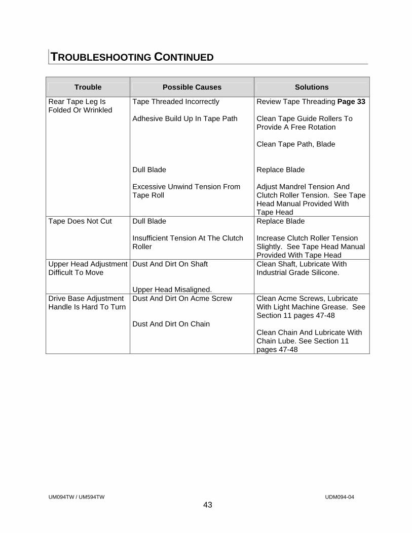
TROUBLESHOOTING CONTINUED
Trouble Possible Causes Solutions
Rear Tape Leg Is Folded Or Wrinkled
Tape Threaded Incorrectly Adhesive Build Up In Tape Path Dull Blade Excessive Unwind Tension From Tape Roll
Review Tape Threading Page 33 Clean Tape Guide Rollers To Provide A Free Rotation Clean Tape Path, Blade Replace Blade Adjust Mandrel Tension And Clutch Roller Tension. See Tape Head Manual Provided With Tape Head
Tape Does Not Cut Dull Blade Insufficient Tension At The Clutch Roller
Replace Blade Increase Clutch Roller Tension Slightly. See Tape Head Manual Provided With Tape Head
Upper Head Adjustment Difficult To Move
Dust And Dirt On Shaft Upper Head Misaligned.
Clean Shaft, Lubricate With Industrial Grade Silicone.
Drive Base Adjustment Handle Is Hard To Turn
Dust And Dirt On Acme Screw Dust And Dirt On Chain
Clean Acme Screws, Lubricate With Light Machine Grease. See Section 11 pages 47-48 Clean Chain And Lubricate With Chain Lube. See Section 11 pages 47-48
UM094TW / UM594TW UDM094-04
44
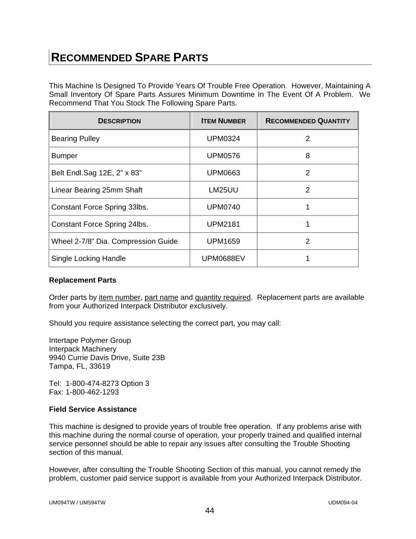
RECOMMENDED SPARE PARTS
This Machine Is Designed To Provide Years Of Trouble Free Operation. However, Maintaining A Small Inventory Of Spare Parts Assures Minimum Downtime In The Event Of A Problem. We Recommend That You Stock The Following Spare Parts.
DESCRIPTION ITEM NUMBER RECOMMENDED QUANTITY
Bearing Pulley UPM0324 2
Bumper UPM0576 8
Belt Endl.Sag 12E, 2” x 83” UPM0663 2
Linear Bearing 25mm Shaft LM25UU 2
Constant Force Spring 33lbs. UPM0740 1
Constant Force Spring 24lbs. UPM2181 1
Wheel 2-7/8” Dia. Compression Guide UPM1659 2
Single Locking Handle UPM0688EV 1
Replacement Parts Order parts by item number, part name and quantity required. Replacement parts are available from your Authorized Interpack Distributor exclusively. Should you require assistance selecting the correct part, you may call: Intertape Polymer Group Interpack Machinery 9940 Currie Davis Drive, Suite 23B Tampa, FL, 33619 Tel: 1-800-474-8273 Option 3 Fax: 1-800-462-1293 Field Service Assistance This machine is designed to provide years of trouble free operation. If any problems arise with this machine during the normal course of operation, your properly trained and qualified internal service personnel should be able to repair any issues after consulting the Trouble Shooting section of this manual. However, after consulting the Trouble Shooting Section of this manual, you cannot remedy the problem, customer paid service support is available from your Authorized Interpack Distributor.
UM094TW / UM594TW UDM094-04
45
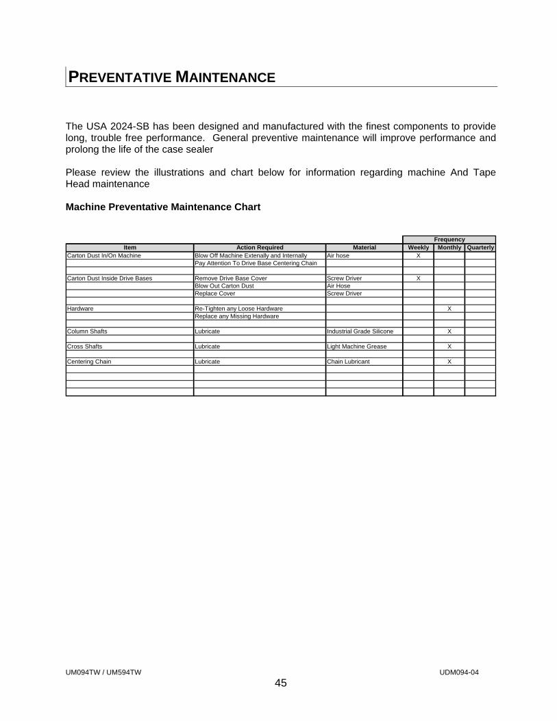
PREVENTATIVE MAINTENANCE
The USA 2024-SB has been designed and manufactured with the finest components to provide long, trouble free performance. General preventive maintenance will improve performance and prolong the life of the case sealer Please review the illustrations and chart below for information regarding machine And Tape Head maintenance Machine Preventative Maintenance Chart
FrequencyItem Action Required Material Weekly Monthly Quarterly
Carton Dust In/On Machine Blow Off Machine Extenally and Internally Air hose XPay Attention To Drive Base Centering Chain
Carton Dust Inside Drive Bases Remove Drive Base Cover Screw Driver XBlow Out Carton Dust Air HoseReplace Cover Screw Driver
Hardware Re-Tighten any Loose Hardware XReplace any Missing Hardware
Column Shafts Lubricate Industrial Grade Silicone X
Cross Shafts Lubricate Light Machine Grease X
Centering Chain Lubricate Chain Lubricant X

UM094TW / UM594TW UDM094-04
46
PREVENTIVE MAINTENANCE Tape Head Preventative Maintenance Chart
Item Action Required Material Weekly Monthly QuarterlyBlade Guard Oiler Pad Lubricate Lightweight oil XHardware Re-tighten any loose hardware X
Replace any missing hardware XCutter Blade Inspect for wear X
Clean Solvent Cleaner XMandrel Assembly Disassemble & Observe X
Mandrel Spring Check for weakness None XMandrel Friction Washer Clean Solvent Cleaner X
Mandrel Metal Washer None None XMandrel Shaft Remove any dust and adhesive build up Solvent Cleaner X
Mandrel Bearing Check for wear None XPeel Roller X
Delrin Roller Check for free spinning. Disassemble and remove any adhesive build up
Solvent Cleaner X
Pivot Shaft Check for any restriction Solvent Cleaner XPeel Roller Spring Check for weakness X
Plastic Guide Rollers Check for free spinning. Disassemble and remove any adhesive build up
Solvent Cleaner X
Knurled PTFE Coated One Direction Clutch Roller
Back off tension. Check for free spinning. Disassemble and remove any adhesive build up
Solvent Cleaner X
Knurled PTFE Coated Guide Roller
Rotation should be slightly restricted by Belville washer. Disassemble and remove any adhesive build up if excessive restriction is detected
Solvent Cleaner X
Front Red Wipe Down RollersRotation should be slightly restricted by Belville washer. Disassemble and remove any adhesive build up if excessive restriction is detected
Solvent Cleaner X
Rear Red Wipe Down Rollers Check for free spinning. Disassemble and remove any adhesive build up
Solvent Cleaner X
Main Spring Remove and inspect for any wear or weakness. Replace as necessary
X
Knife Spring Remove and inspect for any wear or weakness. Replace as necessary
X
Tape Shoe Guide Flat Spring Inspect for any wear or weakness. Replace as necessary
X
Wipe Down Brush Inspect for any wear or weakness. Replace as necessary
X
Main Applying And Wipe Down Assembly
Remove Main Spring and check for any restictions when assembly is in motion
Worn bearings, bent shafts, bent roller arms
X
Knife Arm Assembly Remove Knife Spring and check for any restictions when assembly is in motion
Worn bearings, bent shafts, bent arms
X
Frequency
Refer To Assembly Drawings For Part Numbers Of Replacement Parts If Required
UM094TW / UM594TW UDM094-04
47
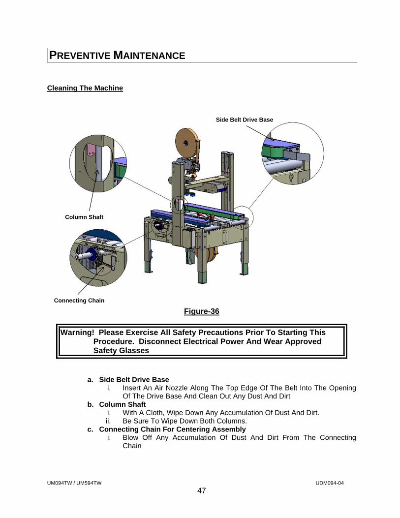
PREVENTIVE MAINTENANCE Cleaning The Machine
Figure-36
Warning! Please Exercise All Safety Precautions Prior To Starting This Procedure. Disconnect Electrical Power And Wear Approved Safety Glasses
a. Side Belt Drive Base i. Insert An Air Nozzle Along The Top Edge Of The Belt Into The Opening
Of The Drive Base And Clean Out Any Dust And Dirt b. Column Shaft
i. With A Cloth, Wipe Down Any Accumulation Of Dust And Dirt. ii. Be Sure To Wipe Down Both Columns.
c. Connecting Chain For Centering Assembly i. Blow Off Any Accumulation Of Dust And Dirt From The Connecting
Chain
Side Belt Drive Base
Column Shaft
Connecting Chain
UM094TW / UM594TW UDM094-04
48
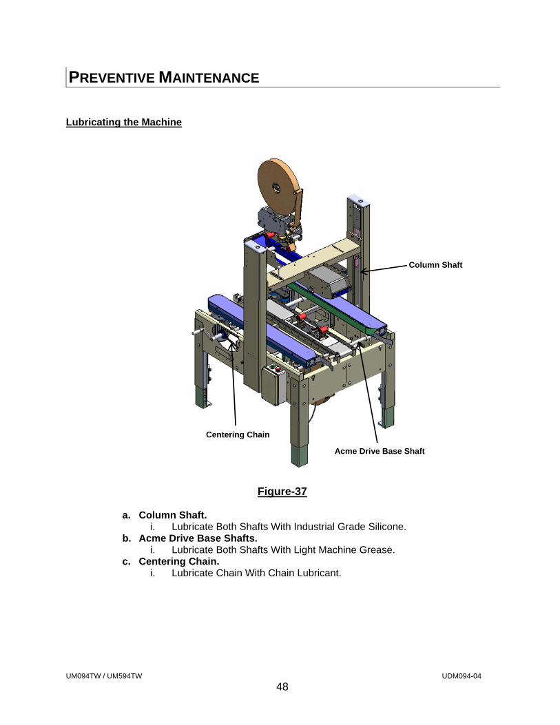
PREVENTIVE MAINTENANCE Lubricating the Machine
Figure-37
a. Column Shaft.
i. Lubricate Both Shafts With Industrial Grade Silicone. b. Acme Drive Base Shafts.
i. Lubricate Both Shafts With Light Machine Grease. c. Centering Chain.
i. Lubricate Chain With Chain Lubricant.
Column Shaft
Centering Chain
Acme Drive Base Shaft
UM094TW / UM594TW UDM094-04
49
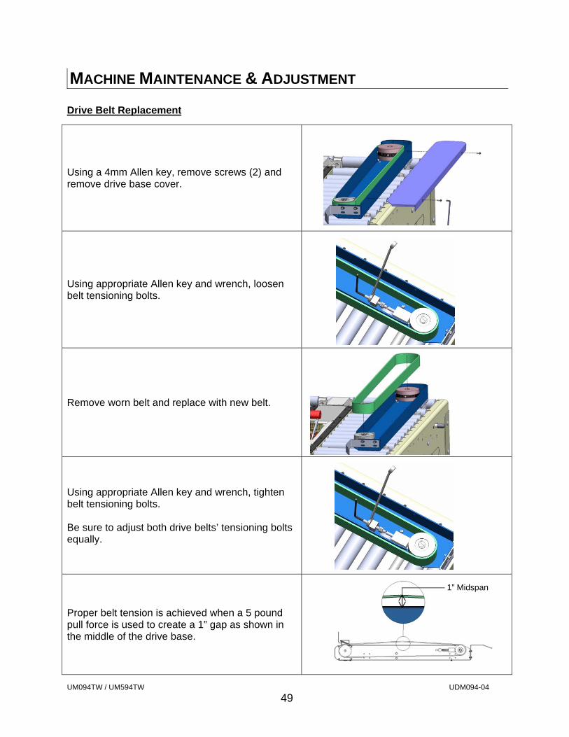
MACHINE MAINTENANCE & ADJUSTMENT Drive Belt Replacement
Using a 4mm Allen key, remove screws (2) and remove drive base cover.
Using appropriate Allen key and wrench, loosen belt tensioning bolts.
Remove worn belt and replace with new belt.
Using appropriate Allen key and wrench, tighten belt tensioning bolts. Be sure to adjust both drive belts’ tensioning bolts equally.
Proper belt tension is achieved when a 5 pound pull force is used to create a 1” gap as shown in the middle of the drive base.
1” Midspan
UM094TW / UM594TW UDM094-04
50
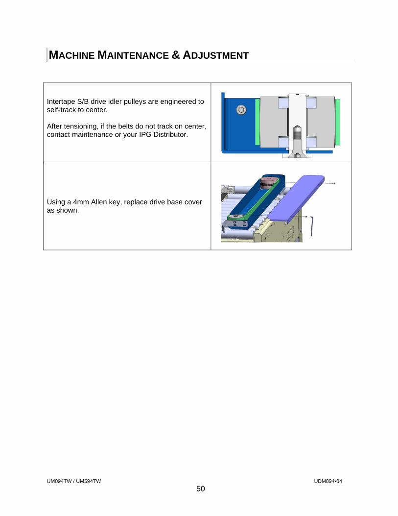
MACHINE MAINTENANCE & ADJUSTMENT
Intertape S/B drive idler pulleys are engineered to self-track to center. After tensioning, if the belts do not track on center, contact maintenance or your IPG Distributor.
Using a 4mm Allen key, replace drive base cover as shown.
UM094TW / UM594TW UDM094-04
51
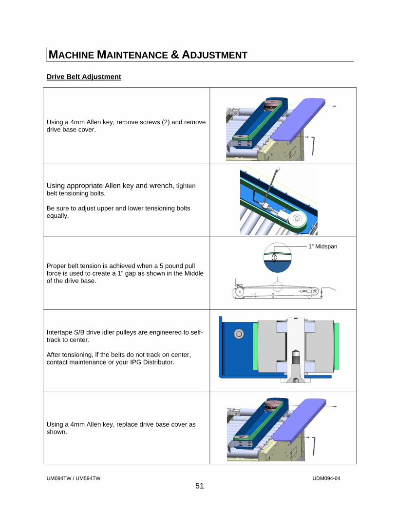
MACHINE MAINTENANCE & ADJUSTMENT Drive Belt Adjustment
Using a 4mm Allen key, remove screws (2) and remove drive base cover.
Using appropriate Allen key and wrench, tighten belt tensioning bolts. Be sure to adjust upper and lower tensioning bolts equally.
Proper belt tension is achieved when a 5 pound pull force is used to create a 1” gap as shown in the Middle of the drive base.
Intertape S/B drive idler pulleys are engineered to self-track to center. After tensioning, if the belts do not track on center, contact maintenance or your IPG Distributor.
Using a 4mm Allen key, replace drive base cover as shown.
1” Midspan
UM094TW / UM594TW UDM094-04
52
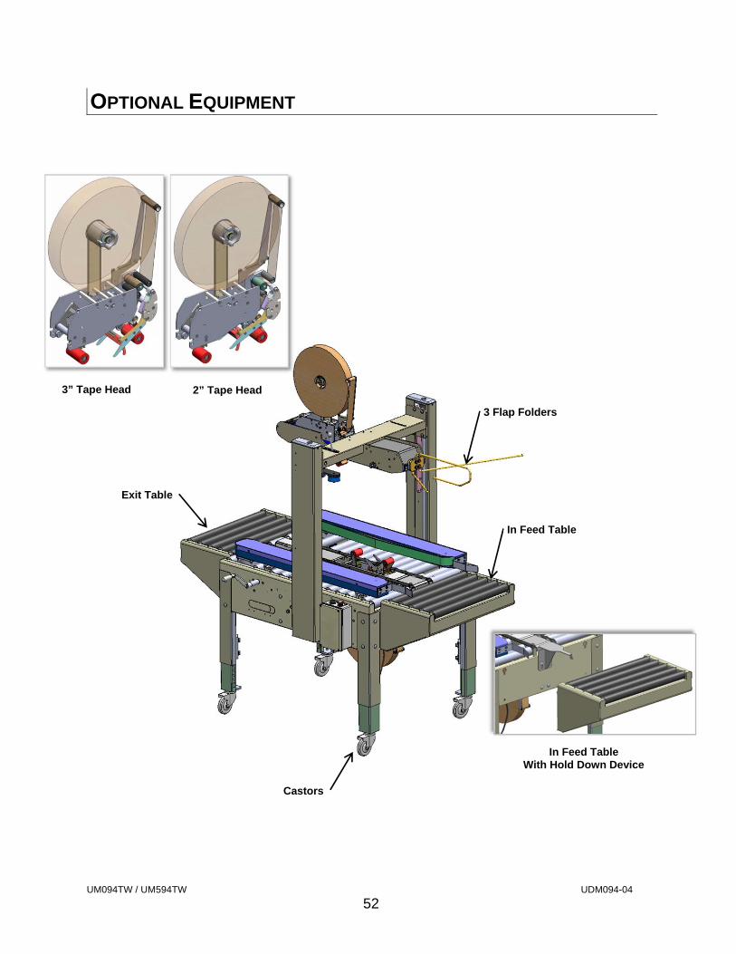
OPTIONAL EQUIPMENT
3 Flap Folders
Castors
Exit Table
In Feed Table
3” Tape Head 2” Tape Head
In Feed TableWith Hold Down Device
UM094TW / UM594TW UDM094-04
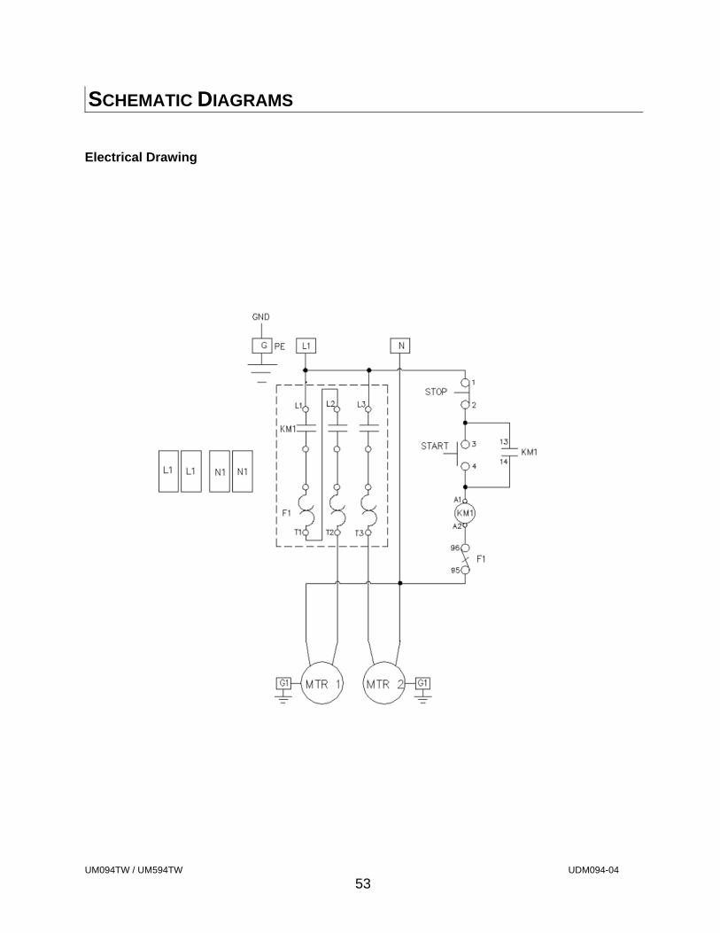
53
SCHEMATIC DIAGRAMS Electrical Drawing

USA 2024-SB METRIC A-1 54
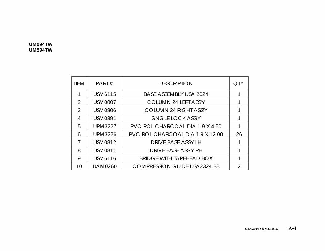
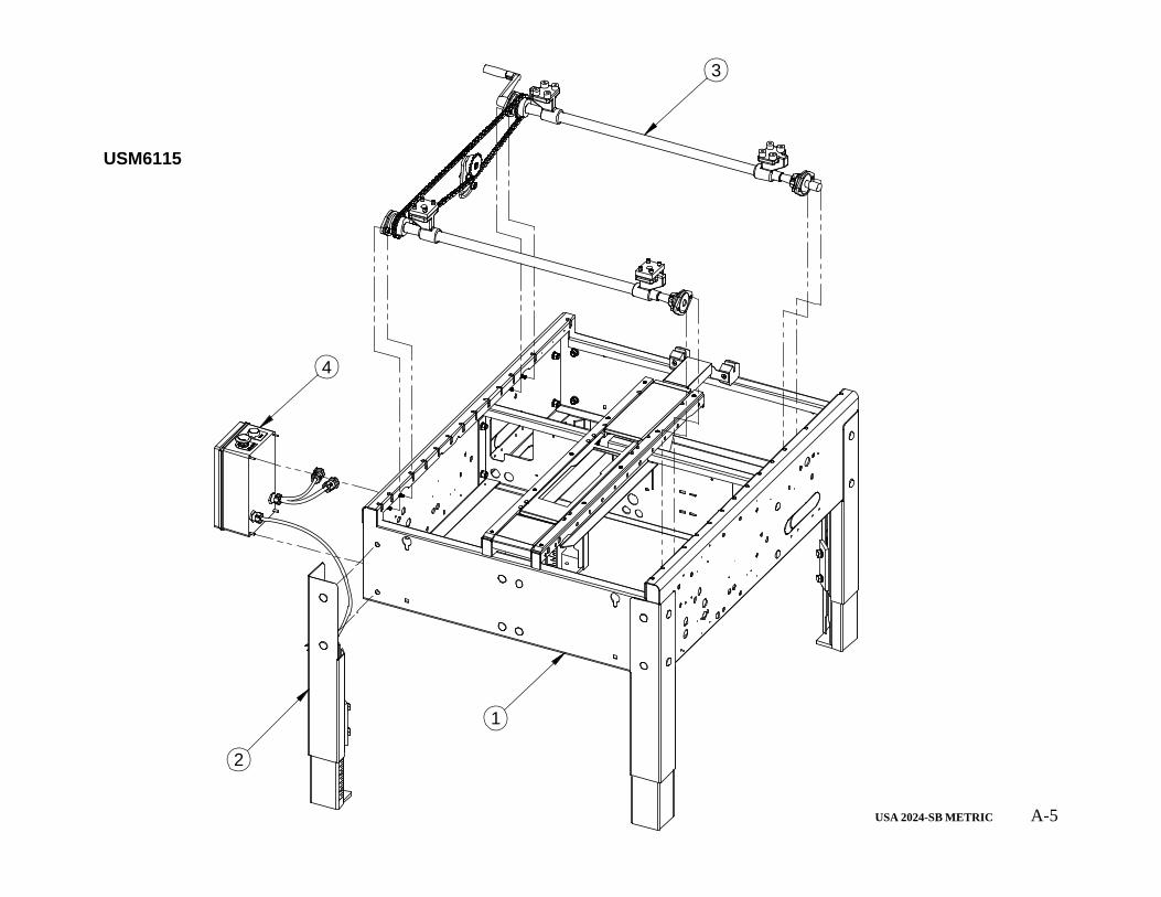
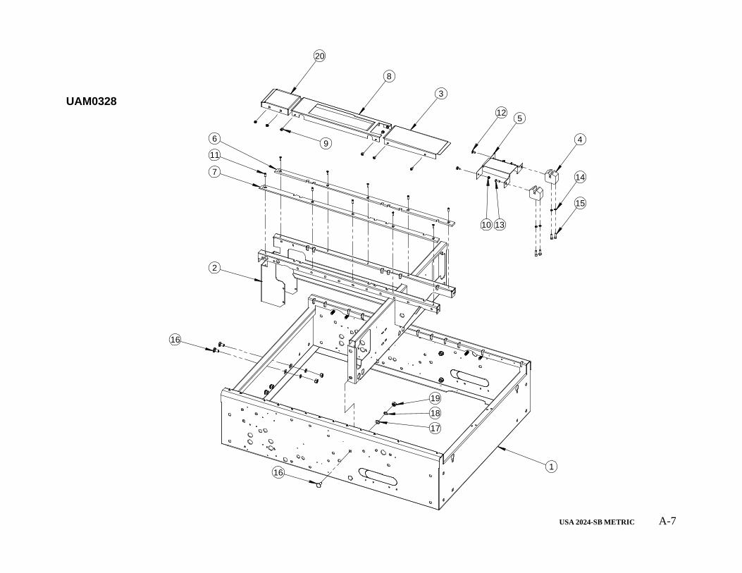
APPENDIX A – ILLUSTRATIONS AND PARTS LISTS
APPENDIX CONTENTS UM094TW/UM594TW (illustration).............................................................................A-3 UM094TW/UM594TW (parts list)................................................................................A-4 BASE ASSEMBLY (illustration)..................................................................................A-5 BASE ASSEMBLY (parts list)......................................................................................A-6 BASE SUB-ASSEMBLY (illustration) ........................................................................A-7 BASE SUB-ASSEMBLY (parts list).............................................................................A-8 LEG ASSEMBLY (illustration).....................................................................................A-9 LEG ASSEMBLY (parts list)........................................................................................A-10 CENTRING ASSEMBLY (illustration)........................................................................A-11 CENTRING ASSEMBLY (parts list)...........................................................................A-12 ELECTRICAL ASSEMBLY (illustration)...................................................................A-13 ELECTRICAL ASSEMBLY (parts list).......................................................................A-14 ELECTRIC BOX (illustration)......................................................................................A-15 ELECTRIC BOX (parts list).........................................................................................A-16 COLUMN LEFT (illustration).......................................................................................A-17 COLUMN LEFT (parts list)..........................................................................................A-18 COLUMN RIGHT (illustration)....................................................................................A-19 COLUMN RIGHT (parts list)........................................................................................A-20 BRIDGE WITH TAPEHEAD BOX (illustration).........................................................A-21 BRIDGE WITH TAPEHEAD BOX (parts list).............................................................A-22
USA 2024-SB METRIC A-2
BRIDGE SUB ASSEMBLY (illustration).....................................................................A-23 BRIDGE SUB ASSEMBLY (parts list).........................................................................A-24 TAPEHEAD BOX (illustration)....................................................................................A-25 TAPEHEAD BOX (parts list).......................................................................................A-26 PIVOT ASSEMBLY LEFT & RIGHT (illustration)....................................................A-27 PIVOT ASSEMBLY LEFT & RIGHT (parts list)........................................................A-28 SINGLE LOCKING DEVICE (illustration).................................................................A-29 SINGLE LOCKING DEVICE (parts list).....................................................................A-30 COMPRESSION GUIDE (illustration).........................................................................A-31 COMPRESSION GUIDE (parts list)............................................................................A-32 DRIVE BASE ASSEMBLY LEFT (illustration)..........................................................A-33 DRIVE BASE ASSEMBLY LEFT (parts list)..............................................................A-34 DRIVE BASE ASSEMBLY RIGHT (illustration).......................................................A-35 DRIVE BASE ASSEMBLY RIGHT (parts list)...........................................................A-36 SECOND E-STOP ASSEMBLY (illustration) ............................................................A-37 SECOND E-STOP ASSEMBLY (parts list).................................................................A-38 SECOND E-STOP BOX (illustration) .........................................................................A-39 SECOND E-STOP BOX (parts list)..............................................................................A-40 ELECTRICAL DRAWING ..........................................................................................A-41
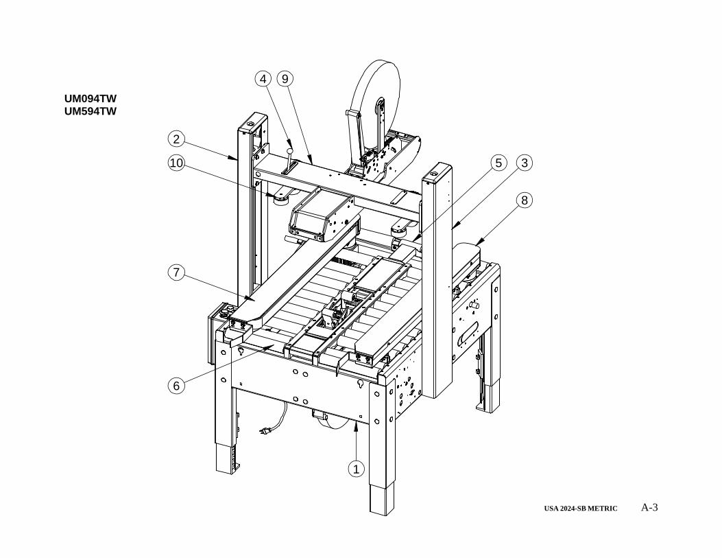
USA 2024-SB METRIC A-3
1
2
3
9
8
10
7
6
5
4UM094TW UM594TW
USA 2024-SB METRIC A-4
ITEM PART # DESCRIPTION QTY.
1 USM6115 BASE ASSEMBLY USA 2024 12 USM0807 COLUMN 24 LEFT ASS'Y 13 USM0806 COLUMN 24 RIGHT ASS'Y 14 USM0391 SINGLE LOCK.ASS'Y 15 UPM3227 PVC ROL CHARCOAL DIA 1.9 X 4.50 16 UPM3226 PVC ROL CHARCOAL DIA 1.9 X 12.00 267 USM0812 DRIVE BASE ASSY LH 18 USM0811 DRIVE BASE ASS'Y RH 19 USM6116 BRIDGE WITH TAPEHEAD BOX 1
10 UAM0260 COMPRESSION GUIDE USA2324 BB 2
UM094TW UM594TW
USA 2024-SB METRIC A-5
1
2
4
3
USM6115

USA 2024-SB METRIC A-6
ITEM PART # DESCRIPTION QTY.
1 UAM0328 BASE SUB-ASS'Y 12 UAM0275 LEG ASSEMBLY METRIC 43 USM6111 DRIVE CENTRING ASS'Y 14 USM0817 ELECTRICAL ASSEMBLY 1
USM6115
USA 2024-SB METRIC A-7
1
19
18
17
16
2
6
11
7
9
8
12
10 13
4
14
15
3
5
20
16
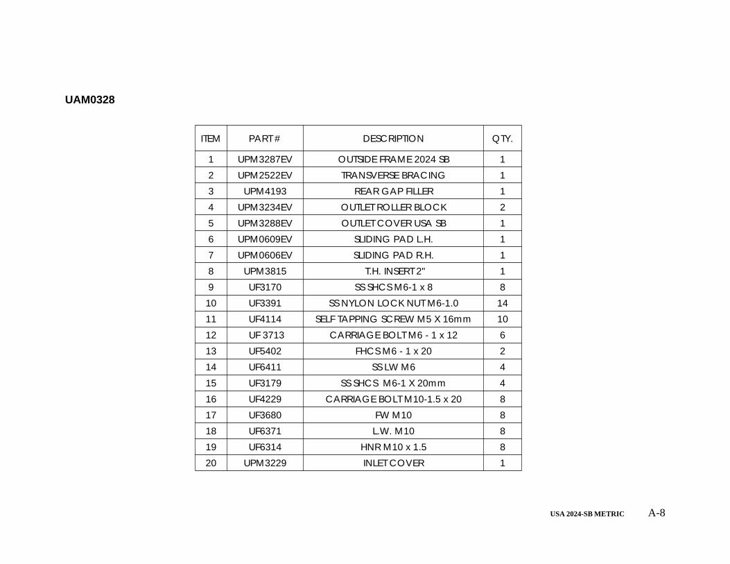
UAM0328
USA 2024-SB METRIC A-8
ITEM PART # DESCRIPTION QTY.
1 UPM3287EV OUTSIDE FRAME 2024 SB 12 UPM2522EV TRANSVERSE BRACING 13 UPM4193 REAR GAP FILLER 14 UPM3234EV OUTLET ROLLER BLOCK 25 UPM3288EV OUTLET COVER USA SB 16 UPM0609EV SLIDING PAD L.H. 17 UPM0606EV SLIDING PAD R.H. 18 UPM3815 T.H. INSERT 2" 19 UF3170 SS SHCS M6-1 x 8 8
10 UF3391 SS NYLON LOCK NUT M6-1.0 1411 UF4114 SELF TAPPING SCREW M5 X 16mm 1012 UF 3713 CARRIAGE BOLT M6 - 1 x 12 613 UF5402 FHCS M6 - 1 x 20 214 UF6411 SS LW M6 415 UF3179 SS SHCS M6-1 X 20mm 416 UF4229 CARRIAGE BOLT M10-1.5 x 20 817 UF3680 FW M10 818 UF6371 L.W. M10 819 UF6314 HNR M10 x 1.5 820 UPM3229 INLET COVER 1
UAM0328
USA 2024-SB METRIC A-9
3
4
67
8
2
1
5
9
10
UAM0275
USA 2024-SB METRIC A-10
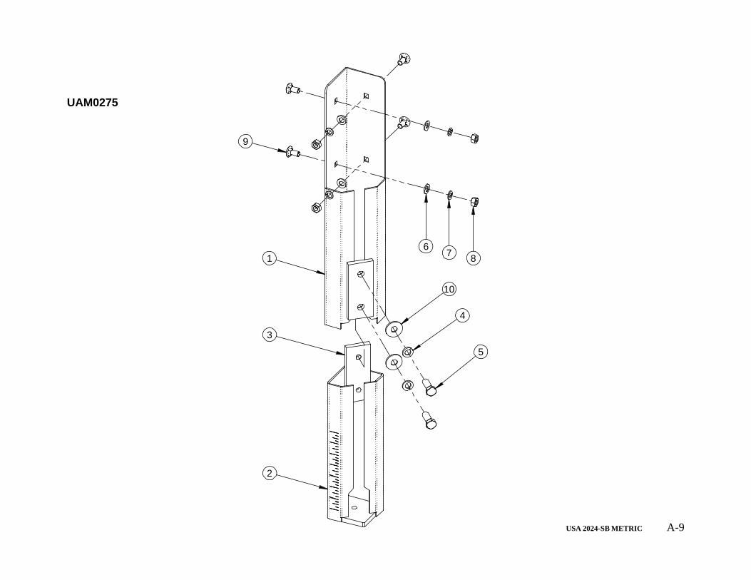
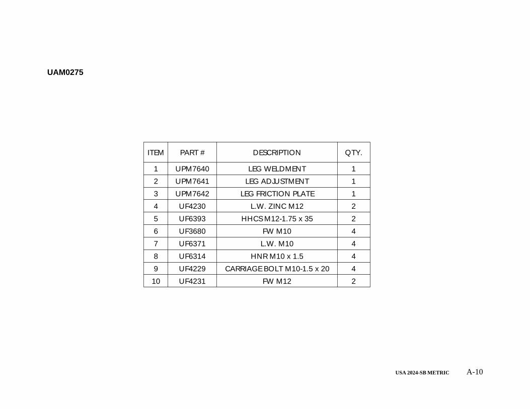
ITEM PART # DESCRIPTION QTY.
1 UPM7640 LEG WELDMENT 1
2 UPM7641 LEG ADJUSTMENT 1
3 UPM7642 LEG FRICTION PLATE 1
4 UF4230 L.W. ZINC M12 2
5 UF6393 HHCS M12-1.75 x 35 2
6 UF3680 FW M10 4
7 UF6371 L.W. M10 4
8 UF6314 HNR M10 x 1.5 4
9 UF4229 CARRIAGE BOLT M10-1.5 x 20 4
10 UF4231 FW M12 2
UAM0275
USA 2024-SB METRIC A-11
182
15
8
17
20
7
16
1
30262913
527
28
634
232422211112
9 1014
25
19
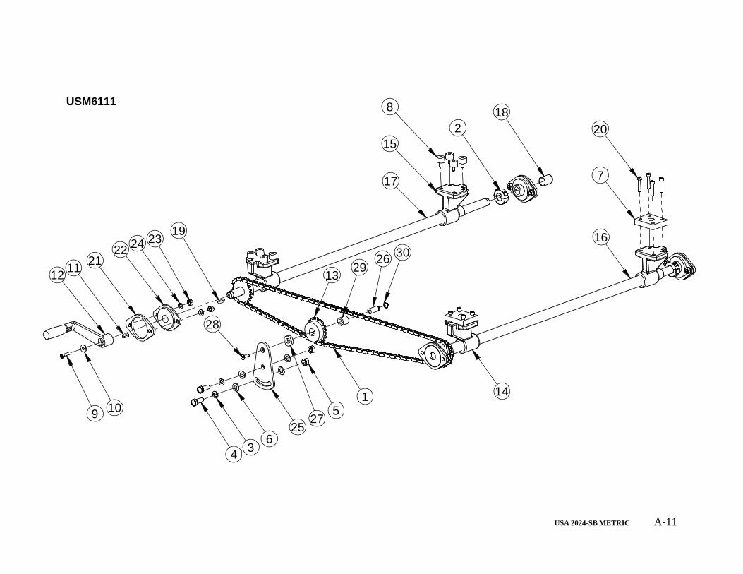
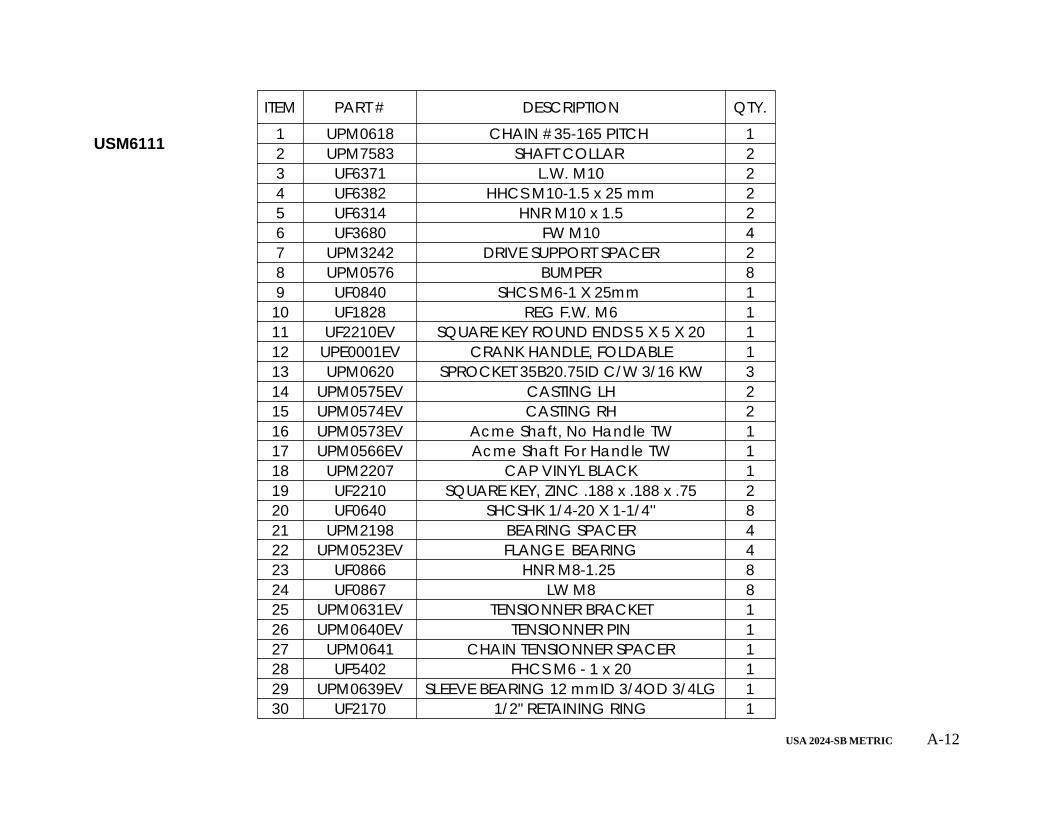
USM6111
USA 2024-SB METRIC A-12
ITEM PART # DESCRIPTION QTY.
1 UPM0618 CHAIN #35-165 PITCH 12 UPM7583 SHAFT COLLAR 23 UF6371 L.W. M10 24 UF6382 HHCS M10-1.5 x 25 mm 25 UF6314 HNR M10 x 1.5 26 UF3680 FW M10 47 UPM3242 DRIVE SUPPORT SPACER 28 UPM0576 BUMPER 89 UF0840 SHCS M6-1 X 25mm 1
10 UF1828 REG F.W. M6 111 UF2210EV SQUARE KEY ROUND ENDS 5 X 5 X 20 112 UPE0001EV CRANK HANDLE, FOLDABLE 113 UPM0620 SPROCKET 35B20.75ID C/W 3/16 KW 314 UPM0575EV CASTING LH 215 UPM0574EV CASTING RH 216 UPM0573EV Acme Shaft, No Handle TW 117 UPM0566EV Acme Shaft For Handle TW 118 UPM2207 CAP VINYL BLACK 119 UF2210 SQUARE KEY, ZINC .188 x .188 x .75 220 UF0640 SHCSHK 1/4-20 X 1-1/4'' 821 UPM2198 BEARING SPACER 422 UPM0523EV FLANGE BEARING 423 UF0866 HNR M8-1.25 824 UF0867 LW M8 825 UPM0631EV TENSIONNER BRACKET 126 UPM0640EV TENSIONNER PIN 127 UPM0641 CHAIN TENSIONNER SPACER 128 UF5402 FHCS M6 - 1 x 20 129 UPM0639EV SLEEVE BEARING 12 mmID 3/4OD 3/4LG 130 UF2170 1/2" RETAINING RING 1
USM6111
USA 2024-SB METRIC A-13
36
21
4
52
3
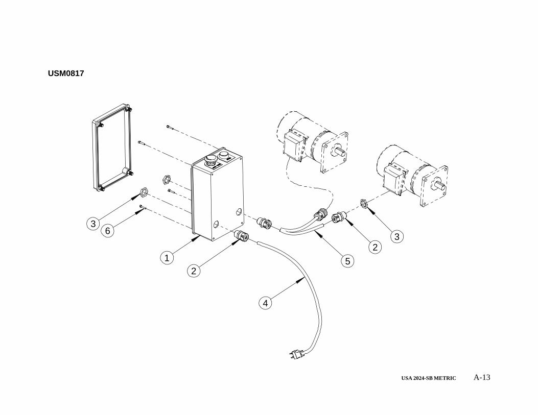
USM0817
USA 2024-SB METRIC A-14
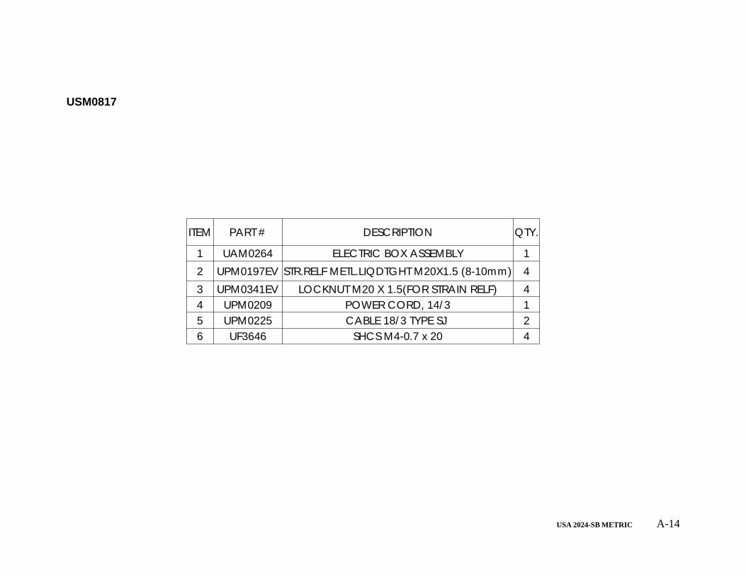
ITEM PART # DESCRIPTION QTY.
1 UAM0264 ELECTRIC BOX ASSEMBLY 12 UPM0197EV STR.RELF METL.LIQDTGHT M20X1.5 (8-10mm) 43 UPM0341EV LOCKNUT M20 X 1.5(FOR STRAIN RELF) 44 UPM0209 POWER CORD, 14/3 15 UPM0225 CABLE 18/3 TYPE SJ 26 UF3646 SHCS M4-0.7 x 20 4
USM0817
USA 2024-SB METRIC A-15
3
7
1
2
6
9
8
5
410
11
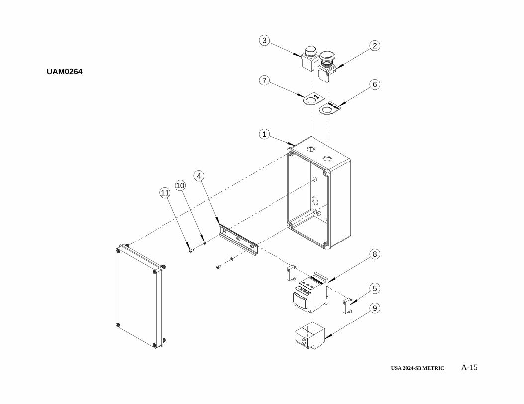
UAM0264
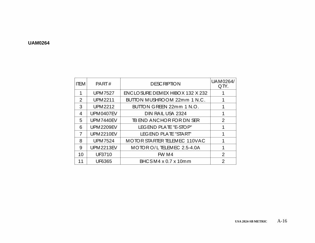
USA 2024-SB METRIC A-16
ITEM PART # DESCRIPTION UAM0264/QTY.
1 UPM7527 ENCLOSURE DEMEX HIBOX 132 X 232 12 UPM2211 BUTTON MUSHROOM 22mm 1 N.C. 13 UPM2212 BUTTON GREEN 22mm 1 N.O. 14 UPM0407EV DIN RAIL USA 2324 15 UPM7440EV TB END ANCHOR FOR DN SER 26 UPM2209EV LEGEND PLATE "E-STOP" 17 UPM2210EV LEGEND PLATE "START" 18 UPM7524 MOTOR STARTER TELEMEC 110VAC 19 UPM2213EV MOTOR O/L TELEMEC 2.5-4.0A 1
10 UF3710 FW M4 211 UF6365 BHCS M4 x 0.7 x 10mm 2
UAM0264

USA 2024-SB METRIC A-17
5
1
67
8
7
6
3
410
119
12
15
16
2
13
14
USM0807
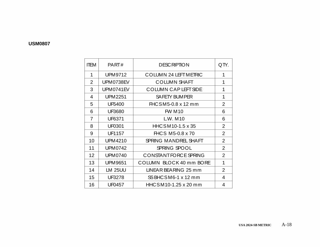
USA 2024-SB METRIC A-18
ITEM PART # DESCRIPTION QTY.
1 UPM9712 COLUMN 24 LEFT METRIC 12 UPM0738EV COLUMN SHAFT 13 UPM0741EV COLUMN CAP LEFT SIDE 14 UPM2251 SAFETY BUMPER 15 UF5400 FHCS M5-0.8 x 12 mm 26 UF3680 FW M10 67 UF6371 L.W. M10 68 UF0301 HHCS M10-1.5 x 35 29 UF1157 FHCS M5-0.8 x 70 2
10 UPM4210 SPRING MANDREL SHAFT 211 UPM0742 SPRING SPOOL 212 UPM0740 CONSTANT FORCE SPRING 213 UPM9651 COLUMN BLOCK 40 mm BORE 114 LM 25UU LINEAR BEARING 25 mm 215 UF3278 SS BHCS M6-1 x 12 mm 416 UF0457 HHCS M10-1.25 x 20 mm 4
USM0807
USA 2024-SB METRIC A-19
5
1
8
7
6
3
410
119
13
16
14
8
76
2
17
15
12
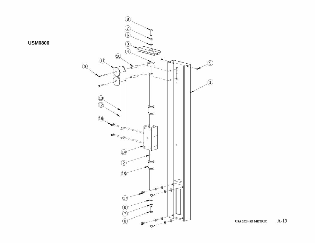
USM0806
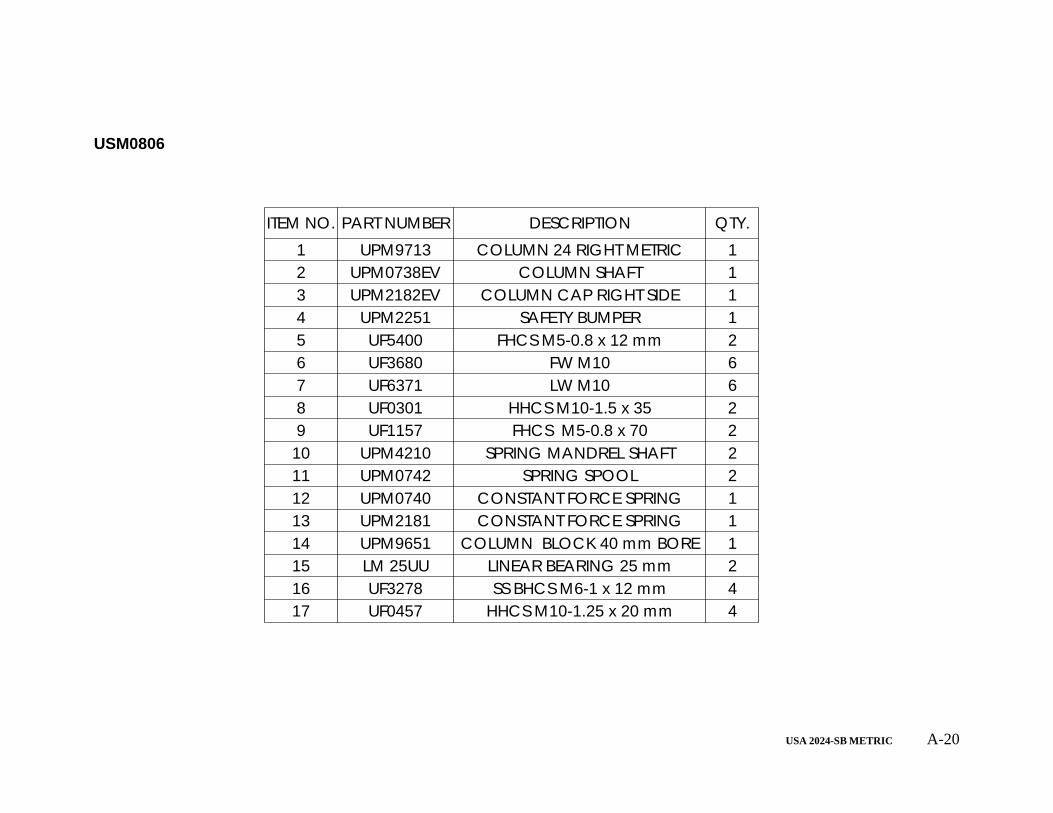
USA 2024-SB METRIC A-20
ITEM NO. PART NUMBER DESCRIPTION QTY.1 UPM9713 COLUMN 24 RIGHT METRIC 12 UPM0738EV COLUMN SHAFT 13 UPM2182EV COLUMN CAP RIGHT SIDE 14 UPM2251 SAFETY BUMPER 15 UF5400 FHCS M5-0.8 x 12 mm 26 UF3680 FW M10 67 UF6371 LW M10 68 UF0301 HHCS M10-1.5 x 35 29 UF1157 FHCS M5-0.8 x 70 2
10 UPM4210 SPRING MANDREL SHAFT 211 UPM0742 SPRING SPOOL 212 UPM0740 CONSTANT FORCE SPRING 113 UPM2181 CONSTANT FORCE SPRING 114 UPM9651 COLUMN BLOCK 40 mm BORE 115 LM 25UU LINEAR BEARING 25 mm 216 UF3278 SS BHCS M6-1 x 12 mm 417 UF0457 HHCS M10-1.25 x 20 mm 4
USM0806
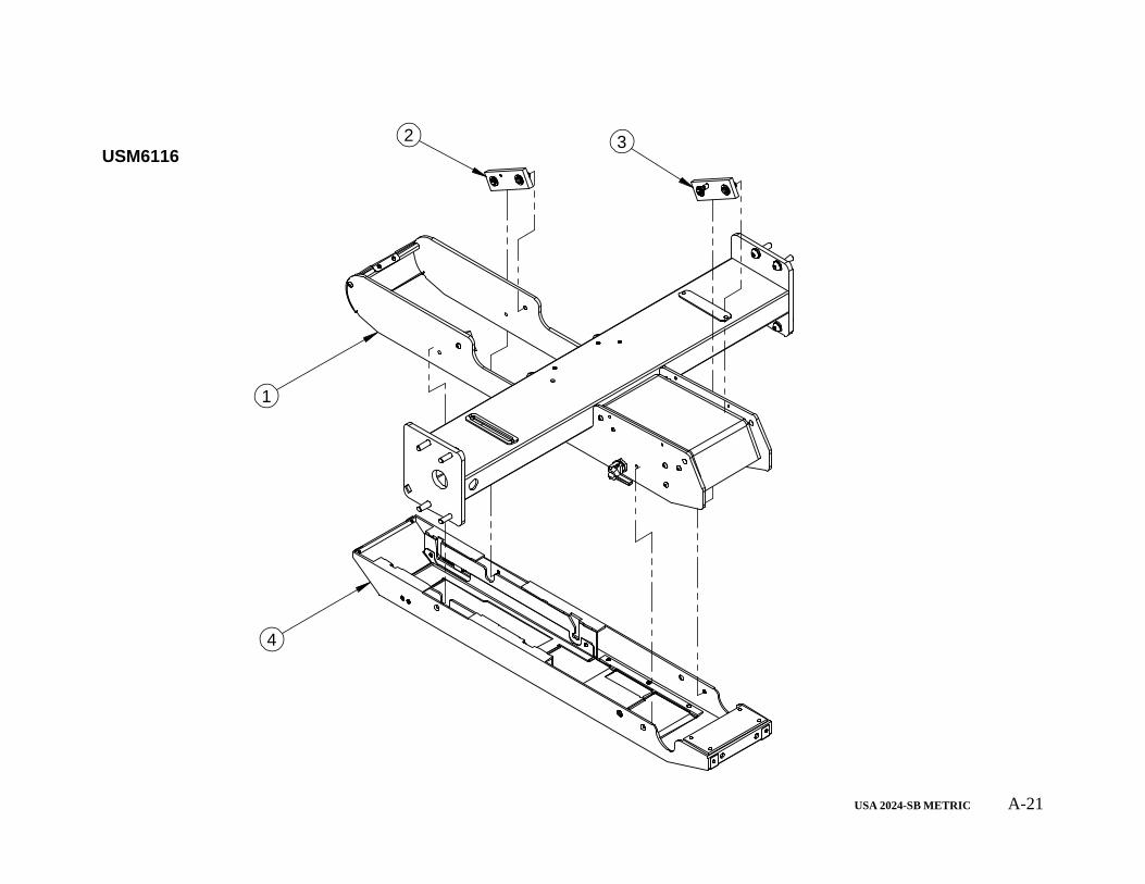
USA 2024-SB METRIC A-21
1
4
2 3USM6116
USA 2024-SB METRIC A-22
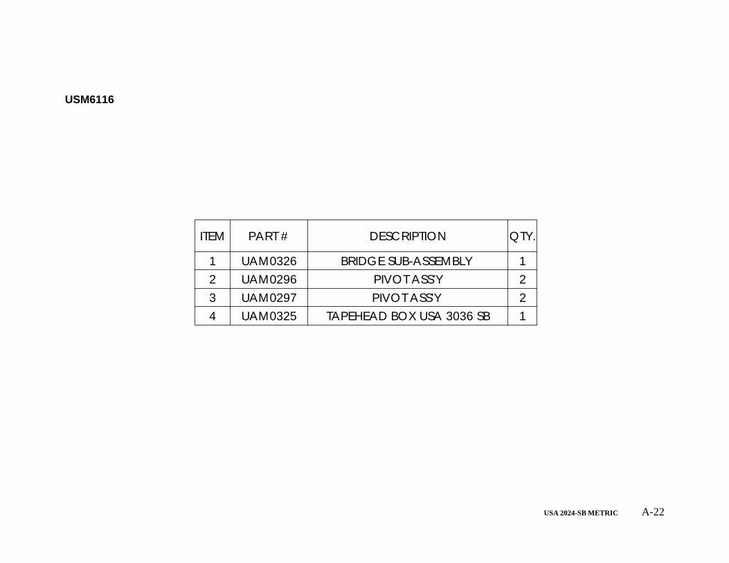
ITEM PART # DESCRIPTION QTY.
1 UAM0326 BRIDGE SUB-ASSEMBLY 12 UAM0296 PIVOT ASS'Y 23 UAM0297 PIVOT ASS'Y 24 UAM0325 TAPEHEAD BOX USA 3036 SB 1
USM6116
USA 2024-SB METRIC A-23
13
5
1
92
14
15
16
3
2019 18
12
14
1110
717 6
4
8
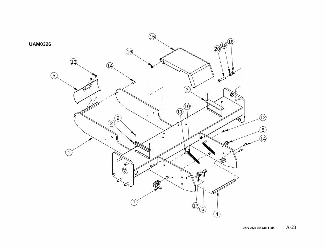
UAM0326
USA 2024-SB METRIC A-24
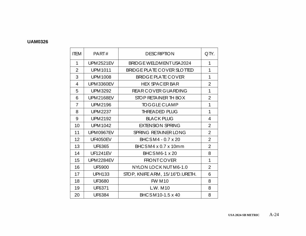
ITEM PART # DESCRIPTION QTY.
1 UPM2521EV BRIDGE WELDMENT USA2024 12 UPM1011 BRIDGE PLATE COVER SLOTTED 13 UPM1008 BRIDGE PLATE COVER 14 UPM3360EV HEX SPACER BAR 25 UPM3292 REAR COVER GUARDING 16 UPM2168EV STOP RETAINER TH BOX 27 UPM2196 TOGGLE CLAMP 18 UPM2237 THREADED PLUG 19 UPM2192 BLACK PLUG 4
10 UPM1042 EXTENSION SPRING 211 UPM0967EV SPRING RETAINER LONG 212 UF4050EV BHCS M4 - 0.7 x 20 213 UF6365 BHCS M4 x 0.7 x 10mm 214 UF1241EV BHCS M6-1 x 20 815 UPM2284EV FRONT COVER 116 UF5900 NYLON LOCK NUT M6-1.0 217 UPH133 STOP, KNIFE ARM, 15/16"D.URETH. 618 UF3680 FW M10 819 UF6371 L.W. M10 820 UF6384 BHCS M10-1.5 x 40 8
UAM0326
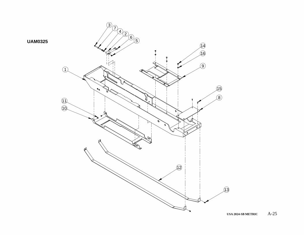
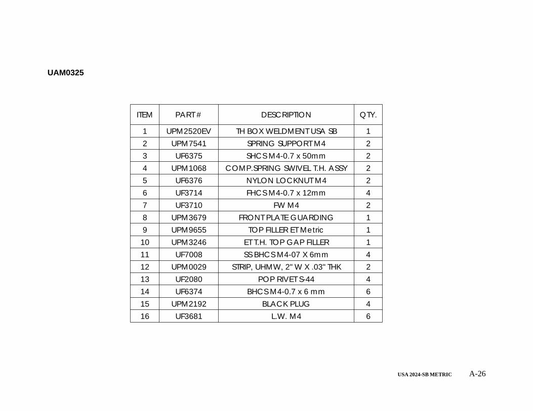
USA 2024-SB METRIC A-25
14
16
9
8
10
11
13
12
15
6
37
24
1
5UAM0325
USA 2024-SB METRIC A-26
ITEM PART # DESCRIPTION QTY.
1 UPM2520EV TH BOX WELDMENT USA SB 12 UPM7541 SPRING SUPPORT M4 23 UF6375 SHCS M4-0.7 x 50mm 24 UPM1068 COMP.SPRING SWIVEL T.H. ASSY 25 UF6376 NYLON LOCKNUT M4 26 UF3714 FHCS M4-0.7 x 12mm 47 UF3710 FW M4 28 UPM3679 FRONT PLATE GUARDING 19 UPM9655 TOP FILLER ET Metric 1
10 UPM3246 ET T.H. TOP GAP FILLER 111 UF7008 SS BHCS M4-07 X 6mm 412 UPM0029 STRIP, UHMW, 2" W X .03" THK 213 UF2080 POP RIVET S-44 414 UF6374 BHCS M4-0.7 x 6 mm 615 UPM2192 BLACK PLUG 416 UF3681 L.W. M4 6
UAM0325
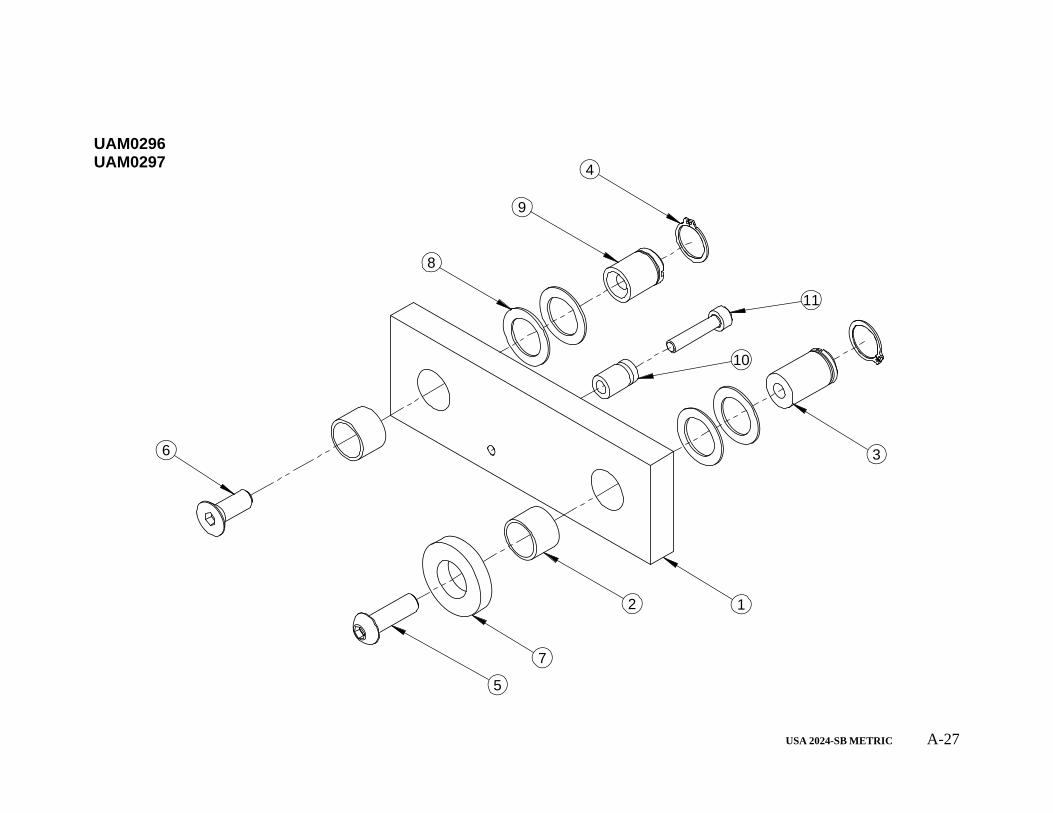
USA 2024-SB METRIC A-27
5
7
2 1
3
4
8
9
6
11
10
UAM0296 UAM0297

USA 2024-SB METRIC A-28
ITEM PART # DESCRIPTION UAM0297/QTY. UAM0296/QTY.
1 UPM1130EV PIVOT PLATE REAR 1 12 UPM9075 BEARING PERMAGLIDE 12 X 14 X 10 2 23 UPM0968EV PIVOT SHAFT LONG T.H. BOX 222 1 14 UF6300 RETAINING RING FOR 12mm SHAFT 2 25 UF1241EV BHCS M6-1 x 20 1 16 UF1192 FHCS M6-1 x 16 mm 1 17 UPM1158 PIVOT SHAFT SPACER 1 18 UF1940 F.W. NYLON 1/2IDx.772ODx.032TH 4 49 UPM2247EV PIVOT SHAFT SHORT T.H. BOX 222 1 1
10 UPM0962EV SPRING RETAINER 1 -11 UF3646 SHCS M4-0.7 x 20 1 -
UAM0296 UAM0297
USA 2024-SB METRIC A-29
3 5
17
4
6
2
8
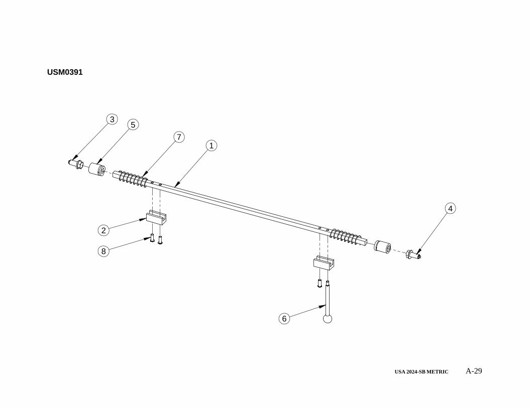
USM0391
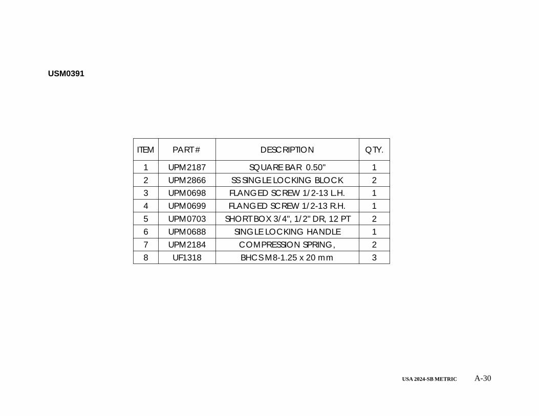
USA 2024-SB METRIC A-30
ITEM PART # DESCRIPTION QTY.
1 UPM2187 SQUARE BAR 0.50" 12 UPM2866 SS SINGLE LOCKING BLOCK 23 UPM0698 FLANGED SCREW 1/2-13 L.H. 14 UPM0699 FLANGED SCREW 1/2-13 R.H. 15 UPM0703 SHORT BOX 3/4", 1/2" DR, 12 PT 26 UPM0688 SINGLE LOCKING HANDLE 17 UPM2184 COMPRESSION SPRING, 28 UF1318 BHCS M8-1.25 x 20 mm 3
USM0391
USA 2024-SB METRIC A-31
2
1
5
4
3
6
7
UAM0260

USA 2024-SB METRIC A-32
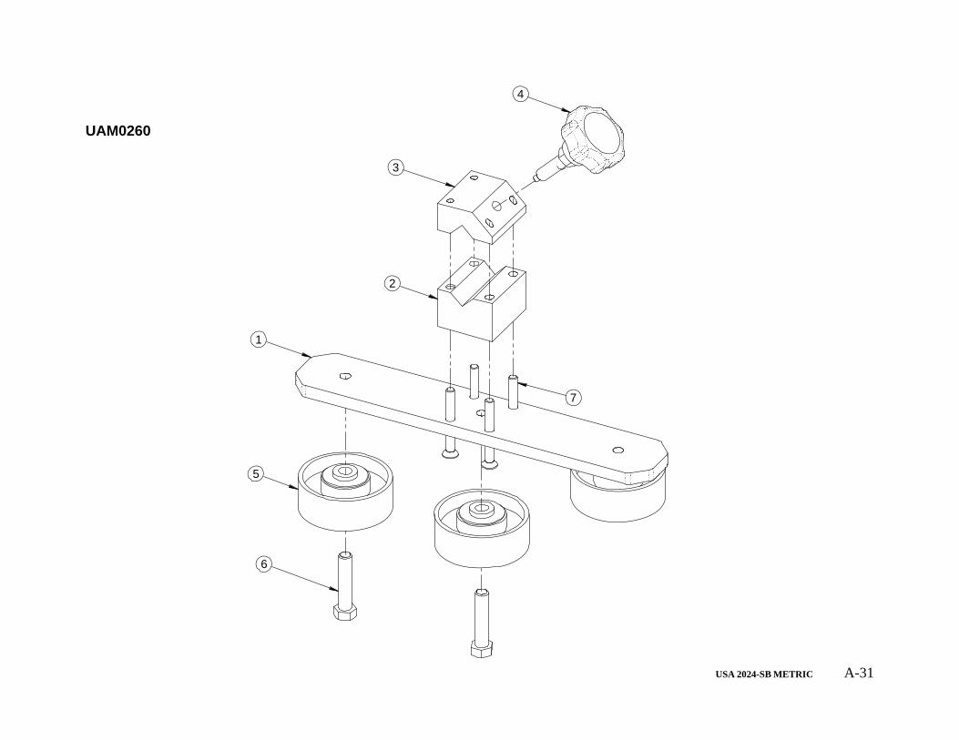
ITEM PART # DESCRIPTION QTY.
1 UPM7491 WHEEL SUPPORT PLATE 12 UPM3285EV GUIDE BLOCK 13 UPM7538EV GUIDE BLOCK TOP 14 UAM0288 KNOB CW 5mm PIN USA2324 15 UPM1659 WHEEL 2-7/8"DIA.COMPR.GUIDE 36 UF0240 HHCS 3/8-16 x 1.75 37 UF6373 FHCS M6 - 1 x 55 4
UAM0260
USA 2024-SB METRIC A-33
229
6
22
1
3
23
13
15
14
16 28 27 18
9
5
24
8
21
7
25
10 1126 20
12
4 19
1817
USM0812

USA 2024-SB METRIC A-34
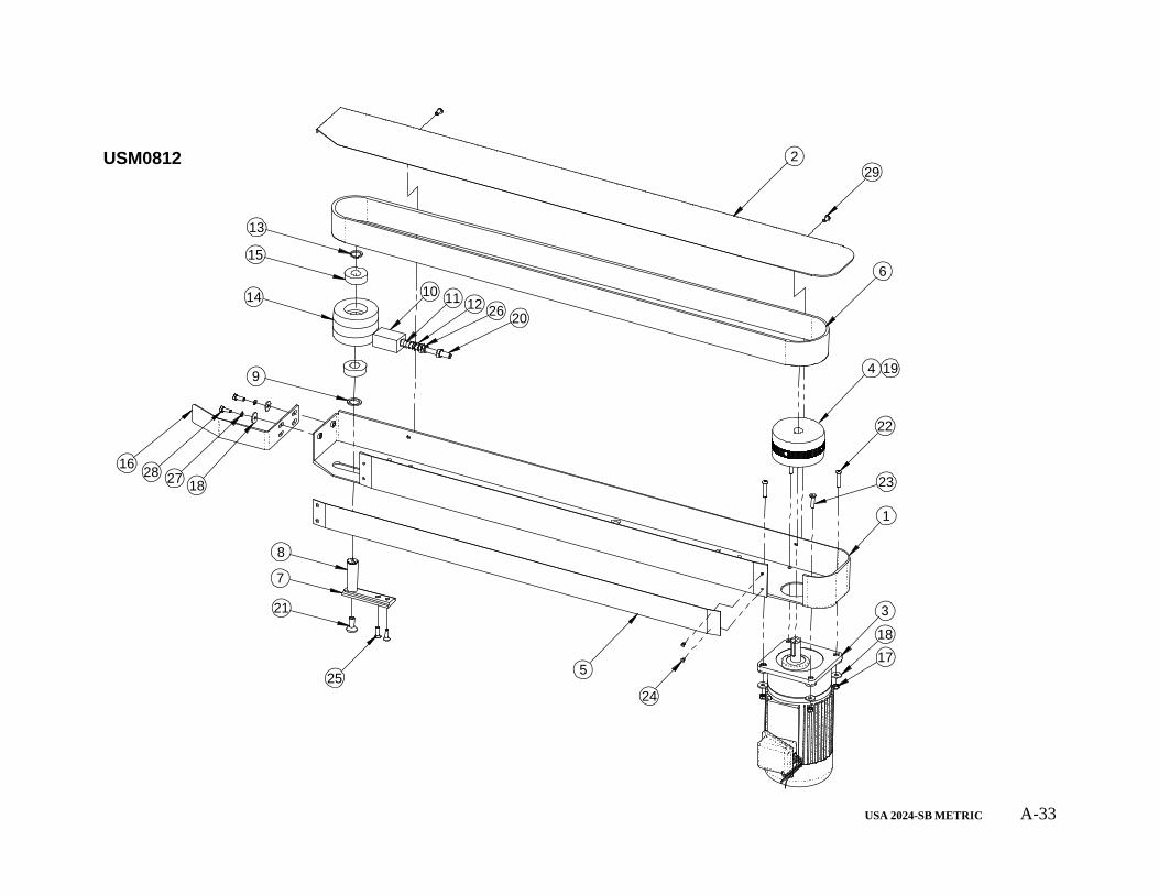
ITEM NO. PART NUMBER DESCRIPTION QTY.
1 UPM3283EV DRIVE BASE LEFT SIDE 12 UPM3281EV DRIVE BASE COVER LH 13 UPM7116 MOTOR 1/3HP 21.4 : 1 14 UPM0129EV DRIVE PULLEY 50mm 15 UPM0029 STRIP UHMW 2" X .03"THK 16 UPM0663 BELT ENDLESS 50 x 2120 mm 17 UPM1879EV TENSIONNER SLIDE 18 UPM1233EV IDLER PULLEY SHAFT 50mm 19 UPM0109 IDLER PULLEY SPACER 110 UPM0101EV TENSIONNER SPRING HOLDER 111 UPM0112 SPRING LOCATOR PIN 112 UPM0038 DIE SPRING (DRIVE BASE) 113 UF2220 EXT RET'G RING 3/4" SHAFT 114 UPM0259 IDLER PULLEY 115 UPM0324 BEARING, PULLEY 216 UPM0647 CARTON RETAINER 117 UF5900 NYLON LOCK NUT M6-1.0 418 UF1828 REG F.W. M6 619 UF3683 SSS M6 X 10mm 220 UF1400 SSS HK 3/8-16 X 3 121 UF1191 FHCS M10-1.5 x 25 122 UF3711 BHCS M6-1 x 30 323 UF1194 FHCS M6 - 1 x 25 mm 124 UF2080 POP RIVET S-44 425 UF5402 FHCS M6 - 1 x 20 226 UF1610 HNJ 3/8-16 327 UF6363 LW M6 228 UF0454 M6-1.0 X 16mm HHCS 229 UF1195 BHCS M6-1 x 12 mm 2
USM0812
USA 2024-SB METRIC A-35
229
12
5
11 18 28
10
7
6
2122
14
13
17
24
23
3
8 915
1
420
16
1918
25
2726
USM0811
USA 2024-SB METRIC A-36
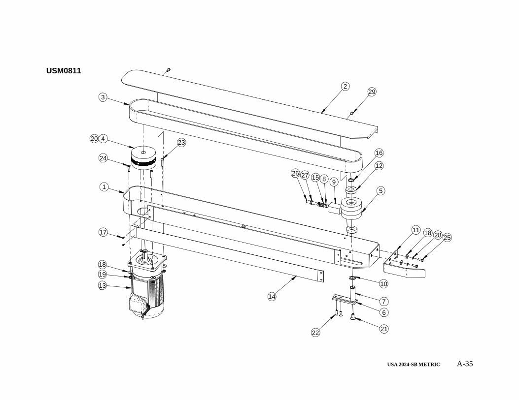
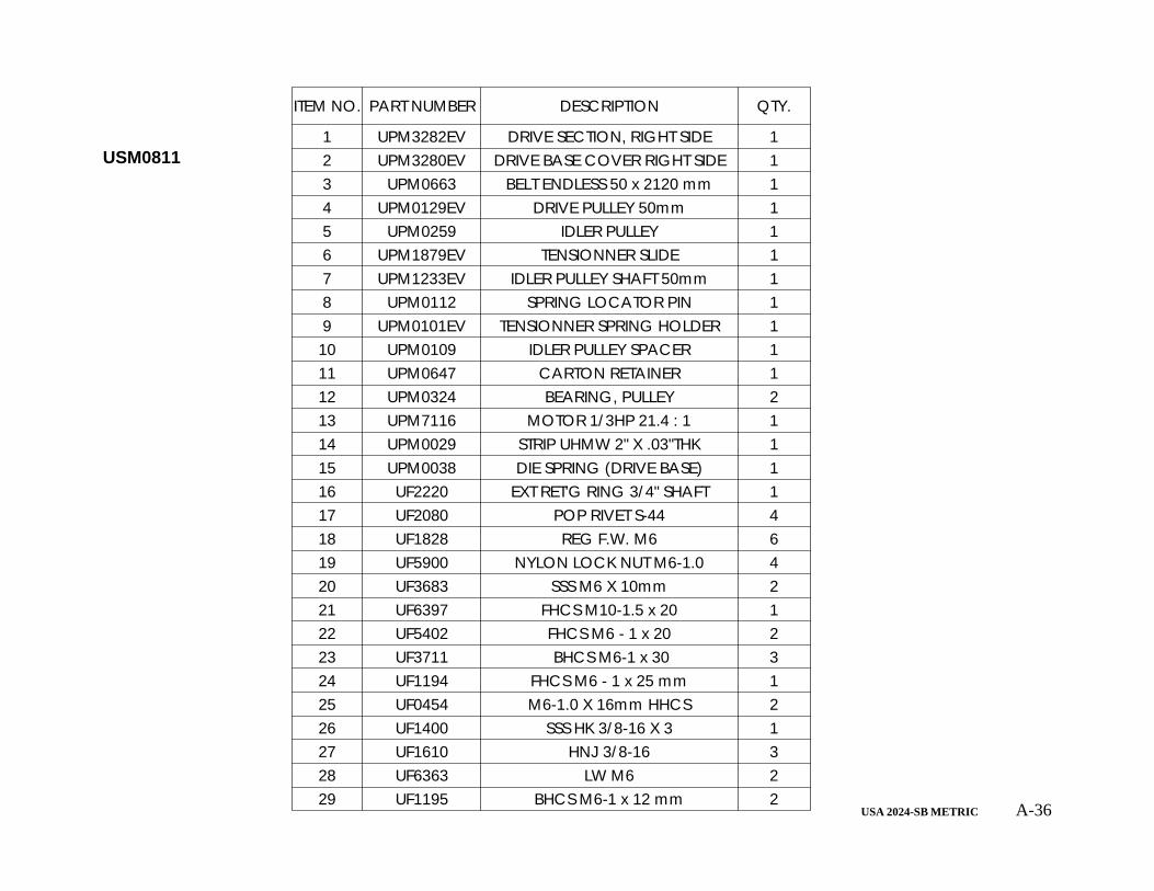
ITEM NO. PART NUMBER DESCRIPTION QTY.
1 UPM3282EV DRIVE SECTION, RIGHT SIDE 12 UPM3280EV DRIVE BASE COVER RIGHT SIDE 13 UPM0663 BELT ENDLESS 50 x 2120 mm 14 UPM0129EV DRIVE PULLEY 50mm 15 UPM0259 IDLER PULLEY 16 UPM1879EV TENSIONNER SLIDE 17 UPM1233EV IDLER PULLEY SHAFT 50mm 18 UPM0112 SPRING LOCATOR PIN 19 UPM0101EV TENSIONNER SPRING HOLDER 110 UPM0109 IDLER PULLEY SPACER 111 UPM0647 CARTON RETAINER 112 UPM0324 BEARING, PULLEY 213 UPM7116 MOTOR 1/3HP 21.4 : 1 114 UPM0029 STRIP UHMW 2" X .03"THK 115 UPM0038 DIE SPRING (DRIVE BASE) 116 UF2220 EXT RET'G RING 3/4" SHAFT 117 UF2080 POP RIVET S-44 418 UF1828 REG F.W. M6 619 UF5900 NYLON LOCK NUT M6-1.0 420 UF3683 SSS M6 X 10mm 221 UF6397 FHCS M10-1.5 x 20 122 UF5402 FHCS M6 - 1 x 20 223 UF3711 BHCS M6-1 x 30 324 UF1194 FHCS M6 - 1 x 25 mm 125 UF0454 M6-1.0 X 16mm HHCS 226 UF1400 SSS HK 3/8-16 X 3 127 UF1610 HNJ 3/8-16 328 UF6363 LW M6 229 UF1195 BHCS M6-1 x 12 mm 2
USM0811
USA 2024-SB METRIC A-37
1
2
7
56
4 3
UM9003

USA 2024-SB METRIC A-38
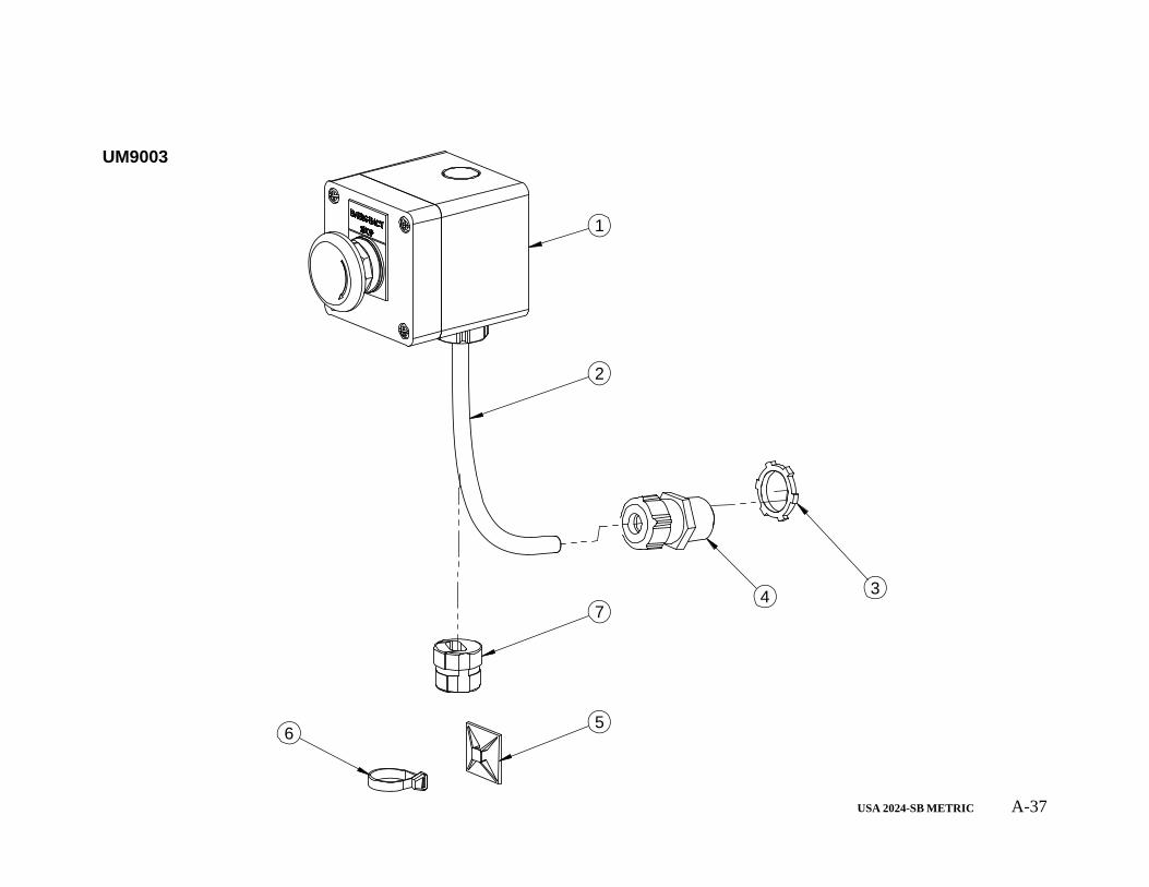
ITEM PART # DESCRIPTION QTY.
1 USM8075 SECOND E-STOP BOX FOR USA 12 UPM0225 CABLE 18/3 TYPE SJ 13 UPM0341 LOCKNUT 1/2"(FOR STRAIN RELF) 14 UPM0197 STR.RELF METL.LIQDTGHT 1/4-3/8 15 UPM0200 MTG. CLAMP,ADH.1.2"X1.2" 16 UPM0222 TY-RAP,5.5"X.14" 17 UPM0285 STRAIN RELIEF, NON-METAL 1
UM9003
USA 2024-SB METRIC A-39
2
3
1
5
4
USM8075
USA 2024-SB METRIC A-40
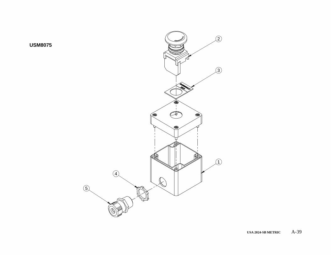
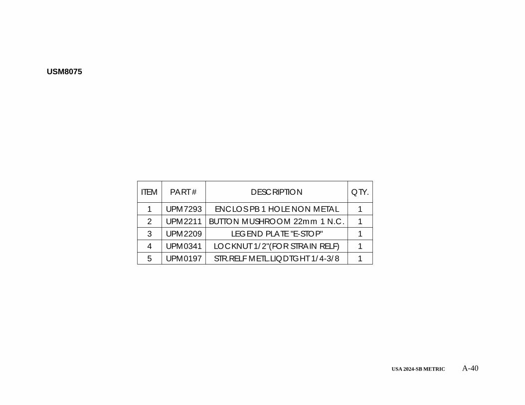
ITEM PART # DESCRIPTION QTY.
1 UPM7293 ENCLOS PB 1 HOLE NON METAL 12 UPM2211 BUTTON MUSHROOM 22mm 1 N.C. 13 UPM2209 LEGEND PLATE "E-STOP" 14 UPM0341 LOCKNUT 1/2"(FOR STRAIN RELF) 15 UPM0197 STR.RELF METL.LIQDTGHT 1/4-3/8 1
USM8075
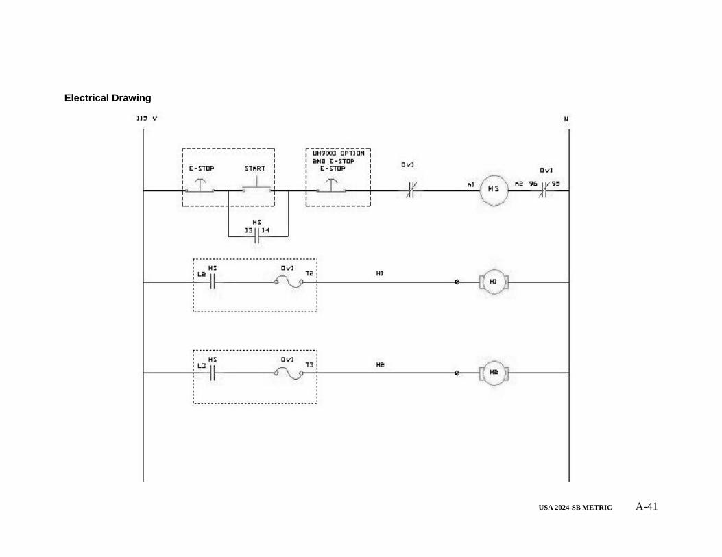
USA 2024-SB METRIC A-41
Electrical Drawing