usaamrdl technical report 72-27 u. s. army · pdf fileusaamrdl technical report 72-27, u. s....
TRANSCRIPT

USAAMRDL TECHNICAL REPORT 72-27
, U. S. ARMY AIRCRAFT IN-FLIGHT FIRE DETECTION ANDAUTOMATIC SUPPRESSION SYSTEMS
ByMa'tthew deliuville
he• 3. Joses
Juy1912L
EUSTIS DIRECTORATEU. S. ARMY AIR MOBILITY RESEARCH AND DEVELOPMENT LABORATORY
FORT EUSTIS, VIRGINIACONTRACT DAAJ02-70-C-0056
WALTER KIDDE & COMPANY, INC.
BELLEVILLE, NEW JERSEY
EApproved for public release;I rdistribution unlimited. 1
Reproduced by
NATVONAL TECHNICALINFORMATION SERVICE
US Deportrvent of ComlmerteSor;ngfield VA 221M1 107

DISCLAIMERS
The findings in this report are not to be construed as an official Department of theArmy position unless so designated by other authorized documents.
When Government drawings, specifications, or other data are used for any purposeother than in connection with a definitely related Government procurement operation,the United States Government thereby incurs no responsibility nor any obligationwhatsoever; and the fact that the Government may have formulated, furnished, or inany way supplied the said drawings, specifications, or other data is not to be regardedby implication or otherwise as in any manner licensing the holder or any other per-son or corporation, or conveying any rights or permission, to manufacture, use, orsell any patented invention that may in any way be related thereto.
Trade names cited in this report do not constitute an official endorsement or approval
of the use of such commercial hardware or software.
DISPOSITION INSTRUCTIONS
Destroy this report when no longer needed. Do not return it to the originator.
SI, *1$
't----',
........... . . .y . ".. ........

UNCLASSIFIEDSecurity Clazinflcatlon
9 a 4 DOCUMtENT CONTROL DATA. R & D(Secwlty claessiica•ion, of title. boo . a o ad f A. Indaalnj aWtt, U5 be ate..d wh She andeU f*oEt IA mlust lbe l)
1. ORIGINATING ACTIVITY (Corporateaut) So. REPORT SECURITY CLASSIFICATION
Walter Kidde & Compaiy, Inc. UNCLASSIFIED675 Main Street 35. GROUP
1JjevIlle. New Jersey3. REPORT TITLE
U. S. ARMY AIRCRAFT IN-FLIGHT FIRE DETECTION AND AUTOMATIC SUPPRESSIONSYSTEMS
4. OESCRIPTIVE NOTEC (2Ypa OftPI and nhdtI.I dalfa)
Final Report AW. AUTHOR(S) (Fir5t nlw@. i[ddue Innitial lost roam)
Matthew deRouvilleRoger B. Jones
S. REPORT OATS 75A. TOTAL NO OF PAGES lb. NO. OF REPS
July 1972 lui 30C5. CONTRACT OR GRANT NO. 5L. ORIGINATORS REPORT NUMbIERPS)
DAAJ02-70-C-00566. PROJECT NO. USAAMRDL Technical Report 72-27
1F162205A529C. F 2 2. OTHER REPORT NOMS) (Any *Off Omi Mat mop be aetmd
1G. OISTRIDUTION STATEMENT
Approved for public release; distribution unlimited.
15. SUPPLEMENTARY NOTES 1Z. SPONSORING MILITARY ACTIVITY
Eustis DirectorateU. S. Army Air Mobility R&D LaboratoryFort Eustis, Virginia
"L-flight fire reports at U.S. Army Materiel System Analysis Agency (combat) andU.S. Army Agency for Aviation Safety (noncombat) for UH-1, AH-1 and CH-47 helicopterswere studied to determine the cause and locatign of helicopter compartment fires. TwoArmy helicopter operating bases were visited for firsthand information. The in-flightfires were divided into groups, and from the number of incidents in each group, a prioritywas established to secure the most effective results toward development of automaticsuppression systems.
A survey was made of fire detectors and methods of extinguishment and suppression, andthe characteristics of such systems were evaluated for possible use in the fire suppressionsystems. System concepts were developed and methods of detection and extinguishment/suppression were selected as most suited for integration into the aircraft system. Designcriteria for the various concepts were developed and recommendations made as to systemsto be used fn the test phase. Simulations of engine, oil cooler, and electronics compartments
were fabricated, and s,,iected systems were tested.
The test program successfully demonstrated the feasibility and performance characteristicsof the detection and automatic suppression systems used.
DD I NovP 695.. OJAP 04lNw, Ic UNCLASSIFIED
.,...IA "...............
Ilecudl Cassdficl•U
"V

UNCLASSIFIED
14. LINK A LINK a
ROLM WY ROLM WT RL =
In-flight Fire Detection and Automatic SuppressionSystems
Helicopter Compartment Fires
Fire Detectors
Fire Extinguishers
Automatic Fire Detection and Suppression System
UNCLASSIFIEDUtwI ae~a~

DEPARTMENT OF THE ARMY
U. S. ARMY AIR MOBILITY RESEARCH & DEVELOPMENT LABORATORYEUSTIS DIRF.CTORATE
FORT EUSTIS, VIRGINIA -. 3604
This report was prepared by Walter Kidde & Company, Inc., under
the terms of Contract DAAJ02-70-C-0056. The techni.al monitor
for this program was Mr. H. W. Holland of the Safety and Surviv-
ebility Division.
The purpose of this effort was to demonstrate the feasibility ofdeveloping an in-flight fire detection and automatic suppressionsystem applicable to typical U.S. Army aircraft. Reports of U.S.Army aircraft in-flight fire were analyzed to determine the areasof the aircraft where in-flight fires occur more frequently. Afterstudy of the various methods of detection, suppression, and ex-tinguishment, a breadboard system was designed, fabricated, andtested to demonstrate the effectiveness of the system.
The conclusions and recommendations contained in this report areconcurred in by this Directorate. Furcher research and develop-ment will be continued in this area to optimize fire detection andautomafic suppression systems for Army aircraft.
Details of illustrations I"this docurnent may be better
studied on microtiche
C_2

Project 1F162205A529Contract DAAJ02-70-C-0056
USAAMRqDL Technical Report 72-27July 1972
U.S. ARMY AIRCRAFT IN-FLIGHT FIRE DETECTION ANDAUTOMATIC SUPPRESSION SYSTEMS
Final Report
By
MATTHEW deROUVILLEROGER B. JONES
Prepared by
Walter Kidde & Company, Inc.Belleville, New Jersey
for
EUSTIS DIRECTORATEU.S. ARMY AIR MOBILITY RESEARCH AND DEVELOPMENT LABORATORY
FORT EUSTIS, VIRGINIA
Approved for public release;distribution unlimited. I
'a

SUMMARY
This report covers a program leading to the successful demonstration of in-flight fire detection and automatic suppression systems in simulated helicoptercompartments.
The in-flight fire reports at U. S. Army Materiel System Analysis Agency(combat) and U. S. Army Agency for Aviation Safety (noncombat) for UH-1,AH-1 and CH-47 helicopters were studied to determine the cause and locationof such fires. Two Army helicopter operating bases were visited for firsthandinformation. The manufacturers of the aircraft, Bell and Boeing-Vertol, werevisited, and the aircraft construction was studied for correlation with the inci-deit reports.
The in-flight fires were divided into groups, and from the number of incidentsin each group, a priority was established to secure the most effective resultsfrom effort expended toward development of automatic suppression systems.
A survey was made cf fire detectors and methods of extinguishment and sup-pression, and the characteristics of such systems were evaluated for possibleuse in the fire suppression systems.
System concepts were developed and methods of detection and extinguishment/
suppression were selected as most suited for integration Into the aircraftsystem.
Design criteria for the various concepts were developed and recommendationsmade as to systems to be used in the test phase. Simulations of engine, oilcooler, and electrontcs compartments were fabricated, and selected systemswere tested.
The test program successfully demonstrated the feasibility and performancecharacteristics of the detection and automatic suppression systems used.
iii

TABLE OF CONTENTSpage
SUM MARY .................................. .............. iii
LIST OF IZLUSTRATIONS .................................. viii
LIST OF TABLES ............................. . .. .. xi
INVESTIGATION OF IN-FLIGHT FIRE INCIDENTS ........... 1
SURVEY OF FIRE DETECTORS ............................ 8
Methods of Detection ......................................... 6Flame Radiation Sensing (Optical) Detectors ................. 7Smoke Detectors ........................................ 8Thermal Detectors, Spot Type ........................... 9Thermal, Continuous Fire Detectors ...................... 10Combustible Vapor Detector ............................. .. 14Explosion Sppression Systems ............................ 15
SURVEY OF METHODS OF CONTAINMENT, EXTINGUISHMENT !AND SUPPRESSION ......................... ............. 16
Extinguishing Agents ........................................ 16Inerting ................................................... 19Methods of Extinguishant Storage and Appication ............. .. 22Available Extinguishers .................................... 24
DEVELOPMENT OF SYSTEM CONCEPTS AND SELECTIONOF METHODS OF SUPPRESSION ............................ 26
Engine Fires . ............................................. 26Oil Cooler Compartment Fires (UH-1) ....................... 28Electrical Fires .......................................... 28Battery Fires ................ ...................... 29Forward Electrical Compartment Fires ....................... 29Aft Pylon Fires (CH-47) .................................... 30Aft Cabin Fires (CH-47) .................................... 30Fuel Cell Fi1'r- .. ........................................ 31Armament and Payload (Cargo) Fires ........................ 32
v

TABLE OF COh fENTS (Cont)Page
AUTOMATIC DETECTION AND SUPPRESSION SYSTEMSREQ1tP EMENTS ............................................ 33
Desi~g Criteria ........................................... 34Continuous Fire Detector (Thermal) ....... ...... 34Radiation Sensing (Flame) Detectors ........................ 34Smoke ')etectors ............... ....... 34Fire Suppression Systems ............................... 35Detector Extinguisher Interface-Unit Design Criteria ......... 35
b't'STEM APPROACH ......................................... 36
Sv-•7 DESIGN" .......................................... 40
aomatic Fire Detection and`%Ippress!on System - Eagine Space. 41Automatic Fire Detection and Suppression %'!stenr - Engine Space. 44Automatic Fire Detectioii and Suppression System - Engine Space. 44AutdMatic Fire Detection and Suppression System - Engine Space. 47AutombatiQ Fire Detection and Suppression System - Engine Space. 47Automatic Fire D3*ection and Suppression System - Engine Space. 50Automatic Fire Detection and Suppression System - Engine Space. 50Automatic Fire Detection and Suppression System - Engine Space. 53Autontatic Fire Detection and Suppression System - Oil CoolerCompartment ....................................... ..... 53
Alternate .............................................. ... . 56Alternates ................................................ 58Automatic Fire Detection and Suppression System .................... 58Alternate ............................................... 61
Automatic Fire Detection and Suppression System - SpacesSurrounding Fuel Cells ........................... ........ 63
Fuel Cell - Automatic Explosion Suppression System ........... 63Alternate ................................................ 65
TEST PROGRAM ...................... ...................... 66
Bench Tests of Detector ..................................... 66Engine Compartment ...................................... 67
Extinguishing Configuration .................. 67Gas Concentration Tests .................................. 67Detecting System Configurations ............................ 69Engine Compartment Test Fires ............................ 74
Oil Cooler Compartment ...... ............................ 82Electronic Compartment ................................... 86
vi

TABLE OF CONTENTS (Cont) Page
CONCLUSIONS ............................................... 88
RECOOMMENDATIONS ......................................... 89
I LITERATURE CITED ..... ..................................... 90
SE-LECTED WBK 7OGRAP/H ...................................... 91
DISTRIBLUTION .. ........................................... 94
vii

LIST OF ILLUSTRATIONS
I Automatic Fire Detection and SuppressionTwo-Space Main and Reserve ExtinguishingSystem ........................................... 42
2 Automatic Fire Detection and Suppression System,Engine Space - Single Thermal Detector, SingleExtinguisher ............... .................... 43
3 Automatic Fire Detection and Suppression System,Engine Space - Single Thermal Detector, Mainand Reserve Extinguishers ....................... 45..4
4 Automatic Fire Detection and Suppression System,Engine Space - Single Optical Detector, SingleExtinguisher .................................... 46
5 Automatic Fire Detection and Suppression System,Engine Space - Single Optical Detectors, Main andReserve Extinguishers ............................. 48
6 Automatic Fire Detection and Suppression System,Engine Space - Dual Thermal Detectors, Self-Interrogating, Single Extinguisher .................. 49
7 Automatic Fire Detection and Suppression System,Engirne Space - Dual Thermal Detectors, Self-Interrogating, Main and Reserve Extinguishers ....... 51
Autom•atic Fire Detection and Suppression System,Engine Space - Dual Optical Detectors, Self-Interrogating, Single Extinguisher ................... 52
9 Automatic Fire Detectiv., and Suppression System,Engine Space - Dual Optical Detectors, Self-Interrogating, Main and Reserve Extin•,ishers ....... 54
10 Automatic Fire Detecticn and Suppression System,Oil Cooler Compartment - Single Optical Detectorand Extinguisher .................................. 55
viii

LIST OF ILLUSTRATIONS (Cont)
Figure Page
11 Automatic Fire Detection and Suppression System,Oil Cooler Compartment - Dual Optical Detectors,Self-Interrogating, Single Extinguisher ................ 57
12 Automatic Fire Detection and Suppression System,Oil Cooler Compartment - Single Optical Detector,Main and Reserve Extinguishers .................... 59
13 Automatic Fire Detection and Suppression System,
Oil Cooler Compartment - Dual Optical Detectors,
Self-Interrogating, Main and Reserve Extinguishers .... 60
14 Automatic Fire Detection and Suppression ElectricalEquipment Space Smoke Detector and Power Shutoff 61
15 Automatic Fire Detection and Suppression ElecricalEquipment Space Smoke Detector, Power Shutoffand Extinguisher .................................. 62
16 Automatic Fire Detection and Suppression SpacesSurrounding Fuel Cells - Thermal Detector,Extinguisher ..................................... 64
17 Automatic Fire Detecticn and Suppression Fuel
Cell Explosion Suppression System .................. 64
18 Automatic Explosion Suppression (Inerting) System -Helicopter Fuel Cells .............................. 65
19 Engine Compartment Mockup ....................... 68
20 Location of Sampling Tubes in Compartment .......... 70
21 Agent Concentration Plot - Zero Airflow .......... 71
22 Agent Concentration Plot - 10 mph Airflow .......... 72
23 Agent Concentratior Plot - 80 mph Airflow .......... 73
ixI

LIST OF ILLUSTRATIONS (Cont)
24 Fire Detector.75
25 Oil Cooler Compartment - External View ........... 8426 Oil Cooler Comparmment - Internal View .......... 85
27 Electronic Compartment ............................ 87
X

LIST OF TABLES
Table Pae
I In-Flight Fire Cause and Location Summary ............ 5
II Comparison of Extinguishing Means ..................... 25
III Cost and Weight Summary ............................. 40
IV Engine Fire Test Summary ............................. 77
V Timed Sequence of Events (Engine Compartment) ........ 83
xi

INVESTIGATION OF IN-FLIGHT FIRE INCIDENTS
The initial approach in this investigation was to study records of past and recentincidents to determine what fires have occurred and the location and cause ofthe fires. Both combat and noncombat incidents were studied.
A visit was made to AMSAA, where combat records are kept, to examine pub-lished reports on the UH-1, AH-1 and CH-47. These reports contain an editedsummary of each incident. Certain incidents were selected from the report andthe original records were examined. In each case, all technical informationhad been included in the incident summary report. Accordingly, all furtherinformation on combat incidents was extracted from the summary reports. Atotal of 58 incidents were studied, of which 55 were in-flight fires.
A visit was made to USAAAVS at Fort Rucker to examine noncombat incidentrecords. Of the some 121 incidents listed for the period January 1967 throughAugust 1970, 97 reports were examined, and of these, only 70 were truly of in-flight fires; the rest were crashes and accidents of various kinds where fireoccurred but was not a factor In causing the accident or in the survivability ofthe aircraft or crew.
Visits were then scheduled to the manufacturers of the aircraft, Bell and Boeing-
Vertol. Visits were made to the Army helicopter operating base at Hunter ArmyAir Field for firsthand discussions with operating crews. No useful informationwas gained on in-flight fires.
During the visits to Bell and Boeing-Vertol, the aircraft were examined indetail. At Bell, the UH-1 construction was examined in relation to the incidentreports. The locations of such equipment as batteries, electrical and radioequipment, oil coolers, heaters, generators, and gearboxes that figured in thefire incidents were noted, along with their relation to combustibles, ignitionsources and possible methods of fire detection and suppression.
The facts resulting from the record studies and the visits as applied to the UH-1are as follows:
1. There were a rather large number of battery fires. These start asoverheated batteries as a result, probably, of overcharging causedby failure of the charging regulator. They can be prevented by dis-connecting the battery when the temperature starts to rise (or thecharging rate becomes excessive). A "burning" battery can beextinguished by first, disconnecting it, and second, cooling it. Thebattery might have ignited combustibles in the area, which willrequire extinguishment.
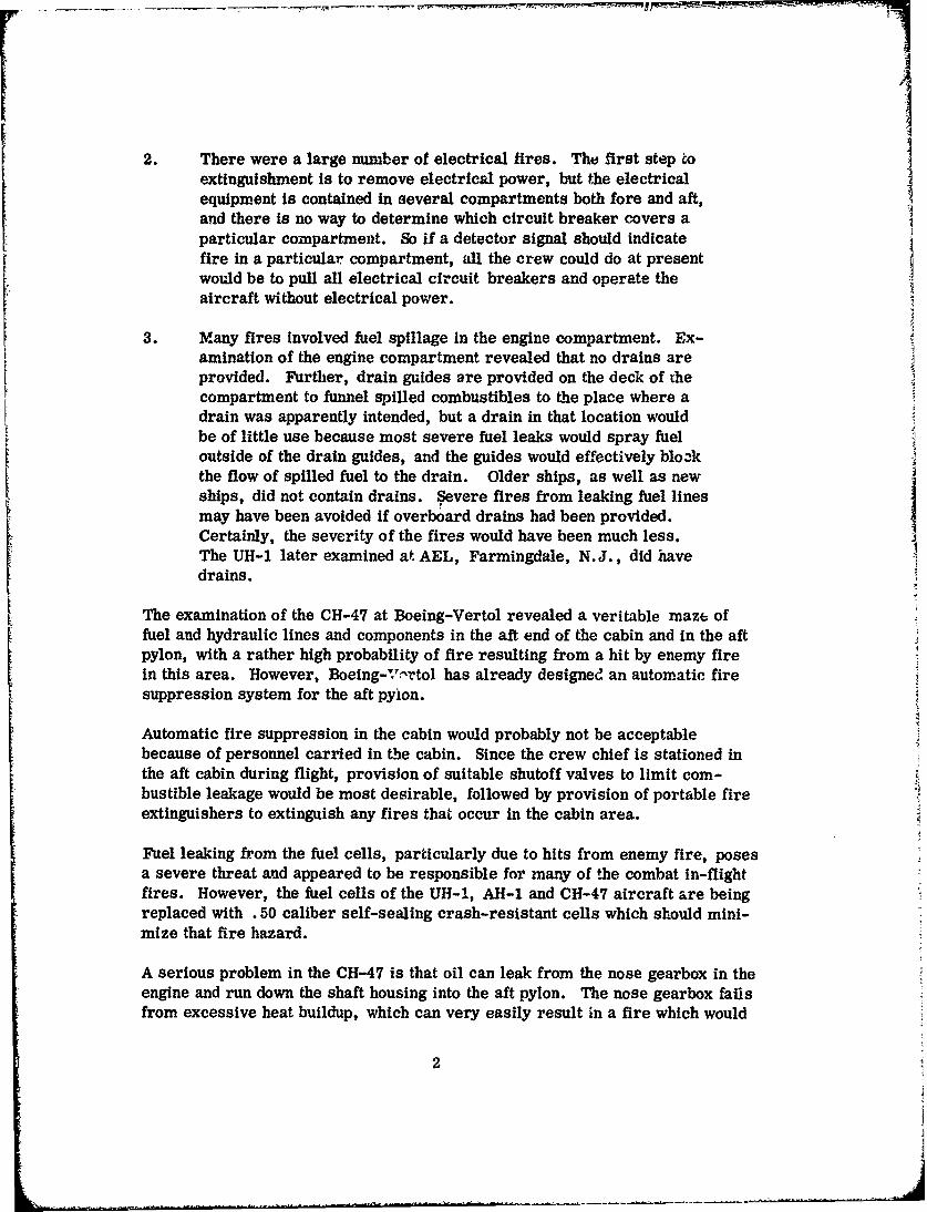
2. There were a large number of electrical fires. The first step toextinguishment is to remove electrical power, but the electricalequipment is contained in several compartments both fore and aft,and there is no way to determine which circuit breaker covers aparticular compartment. So if a detector signal should indicatefire in a particular compartment, all the crew could do at presentwould be to pull all electrical circuit breakers and operate theaircraft without electrical power.
3. Many fires involved fuel spillage in the engine compartment. Ex-amination of the engine compartment revealed that no drains areprovided. Further, drain guides are provided on the deck of thecompartment to funnel spilled combustibles to the place where adrain was apparently intended, but a drain in that location wouldbe of little use because most severe fuel leaks would spray fueloutside of the drain guides, and the guides would effectively blozkthe flow of spilled fuel to the drain. Older ships, as well as newships, did not contain drains. Severe fires from leaking fuel linesmay have been avoided if overboard drains had been provided.Certainly, the severity of the fires would have been much less.The UH-1 later examined at AEL, Farmingdale, N.J., did havedrains.
The examination of the CH-47 at Boeing-Vertol revealed a veritable maze offuel and hydraulic lines and components in the aft end of the cabin and in the aftpylon, with a rather high probability of fire resulting from a hit by enemy firein this area. However, Boeing-Vr'rtol has already designed an automatic firesuppression system for the aft pyion.
Automatic fire suppression in the cabin would probably not be acceptablebecause of personnel carried in the cabin. Since the crew chief is stationed inthe aft cabin during flight, provision of suitable shutoff valves to limit com-bustible leakage would be most desirable, followed by provision of portable fireextinguishers to extinguish any fires that occur in the cabin area.
Fuel leaking from the fuel cells, particularly due to hits from enemy fire, posesa severe threat and appeared to be responsible for many of the combat in-flightfires. However, the fuel cells of the UH-1, AH-1 and CH-47 aircraft are beingreplaced with .50 caliber self-sealing crash-resistant cells which should mini-mize that fire hazard.
A serious problem in the CH-47 is that oil can leak from the nose gearbox in theengine and run down the shaft housing into the aft pylon. The nose gearbox failsfrom excessive heat buildup, which can very easily result in a fire which would
2

then follow the oil down into the pylon. The engine fire detector does not covertUL rea, and the engine fire extinguisher does not reach it either. The pro-posed aft pylon fire suppression system would not cover such fires because thesource is outside the pylon. Some sort of barrier is required to contain suchfires and prevent their propagation into the aft pylon.
In the UH-1, several instances of in-flight explosions were noted, apparently dueto enemy fire striking the fuel cells. Reports (1) (2) on the flammability of fuelcell vapors were reviewed, and it appears that flammable conditions may existin the fuel cells. This is due to the extension of the flammable range caused byvibration. With ignition in the spray pattern, the sea level highly flammablerange may extend from -60°F to +65°F for wide cut faels and from 457F to 180°Ffor aviation kerosenes. I
Summary of Incidents and Aircraft Analgysis
The in-flight fire incidents have been classified as to cause or location of thefire, and are summarized in Table I for the UH-1, AH-1 and CH-47. Theyindicate both combat and noncombat incidents.
Of the 87 in-flight fire incidents in the UH-1,
40 involved fires which started in the engine compartment,of which 21 accompanied engine failure
20 were electrical fires including the battery
11 involved the fuel cells, all combat suffered
The number of incidents for the AH-1 are too few to be of great signi' cance, butof 11 incdents, 5 occurred in the engine compartment.
In the CH-47, five of eight of the noncombat fires were in the engine co',npart-ment. Of the combat incidents, 17 of 16 fires were in the aft cabin and pylon.Electrical or battery fires do not seem to be a problem in this aircraft (onlyone incident).
It thus appears that the greatest effectiveness will be achieved if the followingpriority is observed in instituting suppression means.
1. Engine fires2. Electrical fires3. Fuel cell fires
3

4. Aft cabin (CH-47) fires5. Battery fires6. Off cooler compartment
The armament carried by helicopters presents a special problem. Severalincidents were reported in which rockets burned in their tubes, flares and smokegrenades lit off in the cabin, and a weapon accidentally discharged in the cabinigniting rockets and ammunition. In several other cases, the payload carried bythe aircraft was responsible for the in-flight fire. Dangerous cargo shouldnever be carried aboard an aircraft without special precautions for an emer-gency. The special precautions could be the carrying of special tools or equip-ment. However, for these general cargo aircraft, this is more a matter ofoperating procedures than it is aircraft design.
4

TABLE I. IN-FLIGHT FIRE CAUSE AND LOCATION SUMMARY
UH-1 AH-1 CH-47C* N/C C N/C C N/C Total
Engine failure and fire - 21 - 4 - 1 26
Engine fire, without 10 8 - 1 2 4 25engine failure
Oil cooler compartment - 1 . .. . 1
Electrical fires, cabin - 5 . - - 5
Electrical fires, elec. 2 6 - 2 - 1 11compartment
Electrical fires, engine - 1 .. .. . 1
Fuel cell fires (Internal) 3 -.. .. 3
Fuel cell fires (External) 8 - 1 - 1 - 10
Battery - 6 . .. . 6
Aft Cabin (CH-47) . .. . 7 - 7
Aft Pylon (CH-47) . .. . 2 1. 3
Transmission 1 - - - 2 - 3
Armament (External) 4 - 1 - - - 5
Payload/Cargo 1 6 - 1 1 1 10(Internal)
Unknown and 4 - 1 - 1 - 6Miscellaneous
33 54 3 8 16 8 122
87 11 24
Fires resulting 3 14 1 2 - 4 24from majoraircraft damagebut not a factorin the ensuing crash
TOTAL INCIDENTS 104 14 28 146
C = CombatN/C = Noncombat
5

SURVEY OF FIRE DETECTORS
Recognized manufacturers of fire detectors were surveyed to determine if theirdevices could be used on helicopters. Smoke detectors, combustible vapordetectors, and explosion suppression equipment, as wel) as flame detectorsand thermal type fire detectors, were considered.
METHODS OF DETECTION
The properties of a fire are:
1. The presence of flame2. The release of heat3. The release of products of combustion
Flame can be detected in two general ways:
1. Sense the electromagnetic radiation of the flame. This radiationoccurs across the full light spectrum from ultraviolet to infrared;the intensity at various wavelengths varies with the compositionof the fuel.
2. Sense the ionized gas path created by the presence of flame (orburning gases) between electrodes.
The effects of fire can also be used for detection:
1. The thermal effect - the temperature rise imparted to the burninggases or the surrounding atmosphere can be sensed by thermaldetectors, the hot gases usually reaching the detector by convection.
2. The products of combustion~ - which may be particulate products,such as smoke, or may be gaseous products, such as CO2 .
Many principles can be used to sense the varying properties or characteristicsof fire and flame; over the years many devices have been developed and usedwith varying degress of success. Technical deficiencies and high costs havereduced the fire detection devices for aircraft use to a relatively few. Thisdiscussion will be limited to devices currently available and service proven.
6

Flame Radiation Sensing (Optical) Detectors
Flame detectors are covered by Military Soecifications MIL-F-23447 (WEP) andMIL-D-27729A (USAF) and FAA TSO-C?9. All establish sensitivity in terms ofresponse to a standard test fire, JP-4 burning in a 5-inch pan at a distance of4 feet from the detector. MIL-D-27729A requires response to the standard fire in0.15 second maximum, while thc others allow up to 5 seconds.
Flame detector. This device has two photocells, each sensitive to a different wave-length, one in the visible blue-green region and the othar in the near infraredregion. Hydrocarbon flames emit a preponderance of their energy in Cit rcd An.dyellow region.
Viewing a flame, the device has its red-sensitive cell activated, and electroniccircuitry signals with a relay closure when the cell output reaches a predeterminedvalue representative of a "standard" fire. Sunlight has a high energy output in theblue as well as the red regions. Viewing sunlight, therefore, both the blue and redcells would be activated, but the output of the blue cell is arranged electrically tosuppress the output of the red sensitive cell due to the sunlight. Should a fire bein the field of view and the sunlight not too strong, the red cell output can be stuf-ficient to energize the signal circuit.
The two-color approach eliminates the false warning problem of previous photocell
detectors caused by extraneous sunlight, and recent models are also able to avoidfalse response from the predominantly red light of the setting or rising sun.
It is still a high impedance device (the photocells exhibit resistance in the meg.-ohmregion), and so extreme precautions must be taken against moisture shunting thecell. The high impedance also makes it necessary to take precautions againstvoltages induced by nearby power wires.
Red aircraft beacon lights will produce a false fire signal from the device, and soprecautions should be taken to shield the detector from such light.
Coverage of the hazard area requires a direct line of sight to the possible flamesince the intensity of reflected light is so low. The detector cell is relativelyinsensitive to oil and dust films, but some regular maintenance is necessary tokeep the lens reasonably clean.
The detector cells cannot withstand ambient temperatures above about 300 0F.However, the housing for the detector cells is a sufficient heat sink for the cells
7

that the detector is able to withstand a 2000°F flame for 3 minutes, and thus
should be able to survive for the time it would normally take to detect and ex-tinguish a fire.
The major advantage of this device is its speed of response to fire. At a dis-tance of 10 feet from the standard fire, it responds within 1 second.
Such a detector cannot normally respond to a magnesium flame because of thecolor ratio. However, the device is capable of holding in on a magnesium fireif first activated by a normal hydrocarbon fire.
Installation generally is arranged so that cones of vision of each detector over-lap to the extent that any given area is viewed by two detectors. Up to sixdetectors can be used with a single control unit (the control unit houses theelectronic circuitry).
Ultraviolet radiation detector. Hydrocarbon fires emit considerable radiationin the ultraviolet region, and a detector employing ultraviolet radiation of theproper wavelength would be insensitive to visible light or to smnlight (ult-ravioletbelow 2900 Angstrom is mostly absorbed by the earth's atmosphere, and is notpresent in appreciable intensity below 10, 000 feet altitude). Thus, such adevice should be free of false warnings from extraneous light. Ultravioletsensing devices are generally Gieger-Muller tubes in which photon energycauses emission of electrons from the cathode which ionizes the gas in the tubeand results in an avalanche current. The avalanche can be triggered by cosmicradiation. Such tubes also self-trigger in random fashion. In detector design,the avalanche is gc nerated in regular cycles, with avalanching required In sev-eral consecutive cycles to establish a fire warning. This delays the responseto between 2 and 3 seconds to a standard flame.
Smoke Detectors
Smoke detection devices are divided into two major classes: those which relyon the obscuration or reflection of a light beam by the smoke, and those whichemploy an ionization chamber.
The detectors available for aircraft use employ a light beam and operate onthe reflection of the light beam by the smoke particles.
Ionization chamber. The ionization chamber detectors sense the presence ofsmoke in air as it passes between electrically charged plates where the air isionized by alpha radiation from a nuclear source. Clean air produces a given
8

current flow due to the ionization. The pr,'sence of smoke particles redtces theflow of the ions between the plates and is thus detectable as a current change.
Smoke detector. This detector employs a ';ght beam and photocell in a light-tight chamber. Smoke introduced into the chamber reflects the light beam ontothe photocell and signals an alarm. The reflected light principle gives fail-safeoperation - in the event of lamp failure, the device fails to operate, and no false
signal is given (earlier obscuration- type devicc: caused a false alarm in theevent of lamp failure). The smoke can be introduced to the detector either bynatural convection currents or by forced draft. In the latter Ynethod, a systemof tubes and blowers would be required.
Thermal Detectors, Spot Type -j
A number of such devices are available and operate on a variety of principles;they include resistance bulb thermometers, thermistor probes, thermocouples,and bimetallic switches. In actual practice, resistance bulb thermometers areused for actual temperature indication at various locations in aircraft - oil tem-perature, bleed air temperature, exhaust gas temperature, and the like.Apparently because of the simplicity (only a switch closure for alarm is needel),only bimetallic switches are used for spot fire detectors, and they are the onlydevices approved under the various Military and FAA specifications for thermalspot fire detectors.
One type of thermal spot detector consists of a scaled tube in which two low-expansion struts carry two electrical contacts. When the tube expands longi-tudinally due to heat, the struts are lengthened, straightening the bow and bring-ing the contacts together. When the tube cools, the struts resume their originalbowed position with contacts apart. This simple device is in quite comamon use.Because it is a mechanical device, it is subject to malfunction, and must there-fore be heated periodically to test its functioning. Electrical connections to thedetector can be tested by a simple continuity test.
All spot detectors are limited in detecting fires. Since they can only sense thetemperature of the spot in which they are located, their location must be chosento insure that in the event of fire, they will be in the path of the hot gawes.Because of the stratification and unpredictability of airflow, a rather large num-ber of spot detectors should be employed to be sure one is in the right place forany possible fire.
For this reason, the continuous detector was developed and has virtually sup-planted spot detectors as fire detectors in aircraft engine compartments.
9

Thermal, Continuous Fire Detectors
E. The continuous fire detector is a long capillary tube filled with temperature sen-sitive material, and is capable of sensing a temperature change anywhere alongits length. The capillary can be strung about the hazard area and across airflowpatterns, so that it is highly unlikely that a fire could exist and not have the re-suiting hot gases intercept some portion of the continuous detector. Most con-tinuous detectors are electrical in nature, so electrical connectors are provided
at each end of the capillary, making a "sensing element", as it is generallycalled. Sensing elements may be connected together to make strings 100 feet inlength or more, although generally, systems require less than 50 feet of sensingelement. The elements are generally connected in a loop, with each end of thestring connected to the control unit, which monitors the thermal responsiveelectrical property of the sensing element. With such a loop connection, theelement string can be severed, but since the ends are still connected to the con-trol, it will still be able to sense temperature.
The continuous detector is covered by Military Specification MIL-F-7872C andFAA TSO-Clld which establishes aircraft environmental conditions and minimumresponse sensitivity. Although not required by specifications, additional reli-ability Is obtained by using redundant loops of sensing elements and controls,connecting the two loops in either "AND" or "OR" logic O'epending on the desireof the aircraft ma-ufacturer for the presentation of the fire warning to the crew.Redundant loops, each meeting the specification requirements for a fire detectoralso permit dispatch of the aircraft if one loop should be faulty on preflight test.
Continuous fire detector, thermistor type. In this detector, the capillary is jfilled with a thermistor material in which are embedded the electrical conductors.The thermistor, having a negative temperature coeffiLient, reduces the elec-trical resistance between the conductors when it is heated, rising again whencooled. The control unit monitors the resistance, signalling the alarm when theresistante drops to the preset value corresponding to the predetermined alarmLtemperature. Since the element is essentially an infinite number of thermistorsin parallel, the resistance of the system is a function of the length of elementheated as well as Its temperature, the result being a non-arithmetic averagetemperature indication, weighted to the high temperature areas.
A simple continuity test is sufficient for testing the integrity of the detector loop,
since there is no mechanical actvation or electrical deterioration. A functionaltest of the control unit is accomplished by simulating fire conditions with afixed resistance across the element.
The reliability of the thermistor-type continuous detector is well establ'shedby its long and favorable service.
10
"i':• . . . . • •:• •i• • lr t . .. . •' i' i "'•l •i • •'l-i •'i • i• '' • i " ~ i '1• i-• .... .• • :• •' •• • •'•• .. .. ........ ...

Maintenance requirements of the continuous detector are related to the installa-tion. In modern Installations, the detector element is located with regard tominimizing the damage it may sustain from maintenance operations. In mo.-aircraft, when properly installed, maintenance action for the detector is viLtually nil.
A system which senses resistance and signals an alarm when the resistancedrops below a preset value is subject not only to failure, but to giving a falsewarning if the detector element becomes shorted. The detector uses a discrim-inator circuit which prevents a false warning in the event of a short, convertingLe false warning mode of failure to an inoperative failure.
A novel way of preventing moisture which may finds its way into element con-nectors or into the element itself from shorting the element and causing a falsewarning or inoperative system is done by operating the detector element at aDC voltage too low to overcome the polarization potential of salt water, so thatconduction is very low and consequently salt water would appear as a highresistance.
The continuous detector is installed by attaching the detector element at closeintervals (6 inches - 9 inches) to aircraft structure, or directly to the engine,routed in the general paths of airflow and adjacent to sources of combustibleleakage.
In many cases, the detector element is attached to the compartment fire wall toindicate the presence of excessive heat at that fire barrier. The control unit Islocated outside the fire zone. The detector element connector can be used topenetrate the fire wall, but whe:.e this is not practicable, fire zone wire is usedfor electrical connections to the element. Care must be taken in the routing ofthe element and its connecting wires to prevent chafing which could result inshort circuits and a resulting inoperative system. In many modern installations,special support structure is provided for the detector elements, and in somecases, the elements are shrouded for protection.
The fire detector specifications, both Military and civil, require that the detectorrespond in less than 5 seconds when 6 inches of length iq immersed in a 2000°Fflame. In an actual aircraft fire, response may be anywhere from 1 second to10 seconds depending on the intensity of the fire, but a good approximation for
an active fire when the element is in the path of the hot gases is about 3-1/2seconds.
Detector elements are available in diameters of. 045 and. 065 inch in a~ditionto the .090 inch diameter standard. These smaller elements would give fasterresponse (40% and 60% of the standard response time), but at a sacrifice in
11
iI

ruggedness. The smaller elements, therefore, should be used only when theinstallation would permit the lesser degree of ruggedness.
This thermistor type detector meets the requirements of MlL-F-7872C andFAA TSO-CId and is therefore suitable for aircraft use.
Continuous detector. eutectic salt type. In this device, the capillary is filledwith a porous insulator surroandirg the conductor, impregnated with a eutecticsalt that melts at the desired alarm temperature. When the salt melts, it con-ducts and acts as a low resistance path - it effectively acts as a switch, chang-ing from a very high to a very low resistance over a very narrow temperaturerange of approximately 207F. An AC potential must be used to operate the
detector element, since DC causes metallic plating out on the insulator andpermanent shorting of the detector.
Because of the sharp switching action of the melting nalt, the detector operatesat a discrete temperature, virtually unaffected by the length of element heated.Thus, this is a fixed temperature device, essentially nonaveraging.
The diameter of the capillary is approximately .090 inch, but its length is re-stricted to 15 feet maximum for individual elements. Elements can be strung
together to form a practically unlimited total length.
As with the thermistor-type continuous detector, a simple continuity test isadequate to test the integrity of the device, since, again, there is no mechanicalactuation.
Since the co:itrol monitors the resistance, and signals a low resistance, a shortcircuit results in a false alarm. Because the rate of resistance charge of themeldg salt approaches that of a short circuit, discrimination between heat andshort circuits is difficult to obtain, and consequently a short discriminator cir-cuit becomes quite complex and discrimination may be unreliable. With redun-dant detector loops, short discrimination is provided inherently, and discrim-ination circuits become less necessary.
With AC applied voltages, moisture in element connectors will appear as a lowresistance, but the detector is able to operate at a very low resistance level(20 ohms) and to avoid false warnings. However, atmospheric moisture enter-Ing a breach in the capillary will dissolve the salt, and the dissolved salt willconduct and give a false warning.
The time response of this type detector appears faster than the response of asimilar size thermistor element because the short length in the flame test neednot be heated as high as the averaging thermistor element. In actual installations,
12

however, there would be little difference in response to a fire because a longerlengui of element would be heated by the fire and the overall ambient would alsorise; these conditions do not affect the response of the eutectic element, but dospeed the thermistor response.
This ty, detector is in service in many civil and Military aircraft, and con-forms to MIL-F-7872A and FAA TSO-Clld.
Continuous fire detector, capacitance type. This device is similar in construc-Lion to the thermistor types, and in fact contains a thermistor, but the charac-teristic monitored is the capacitance of the detector element. The capacitance
has a positive coefficient - it rises with temperature. The capacitance effect isemployed by applying a DC voltage to the element at intervals and sensing be-tween application intervals to see if the charge is retained. The magnitude ofthe retained charge is a measure of the capacitance. The alarm point is set atthe magnitude corresponding to the desired temperature.
Since the detector is essentially an infinite number of capacitances in parallel,it too indicates an average temperature; but since the capacitances averagearithmetically, the temperature average is less heavily weighted to the hightemperature areas.
Since the monitoring circuit is not measuring a reduction in resistance, a shortcircuit does not cause a false warning. A short does render the detector inop-erative.
The thermistor resistance also tends to short the capacitance at high tempera-tures where the resistance is low, and while means are taken to overcome theproblem in the design of the electrical circuit, the detector does have the pozsi-
bility of not responding to very rapid heating where the element resistancesuppresses the capacitance. This is a serious factor, however, only in suchfires as torch-like burn-throughs, or very hot fires formed in the presence of
high airflow.
Continuous fire detector, pneumatic type. In this device, the capillary is filledwith a solid material which outgasses heavily when heated above a critical dis-sociation temperature. A void space is maintained between the outgassingmaterial auLd the capillary wall by a spiral wrap of metal. Thus, when out-gassing occurs, a pressure buildup is transmitted down the capillary to a pres-sure switch at one end, which in turn signals the alarm. This outgassingoccurs at a discrete temperature which depends on the dissociation temperatureof the outgassing material, and is of such volume as to be independent of thelength of element heated. However, the gas in the void space expands as theelement temperature increases (below the dissociation temperature) and gen-erates a pressure which actuates the pressure switch. This pressure is
13

dependent on the volume of gas heated, and thus directly on the length of elementheated. It provides a temperature indication that is an arithmetic average of theelement temperatures. This arithmetic average makes it insensitive to shortlengths heated and so depends either on the discrete outgassing temperature fora fire alarm, or on a rather extensive general heating of the compartment.
The outgassing material is a selected metal hydride, which dissociates into themetal and hydrogen. Upon cooling the detector after outgassing has occurred,the hydrogen recombines with the metal, reforming the hydride.
If a small leak occurs in the capillary, the averaging function may not operate,but the hydride formation is voluiminous enough to overpower all but a massiveleak. With a leak, enough hydrogen may be lost to prevent reformation of thehydride on cooling, so that the detector may not operate a second or third time.A further problem is that a dent in the capillary may block or restrict the flowof gas so as to slow, or even prevent, response.
A simple continuity test of the capillary is not sufficient to establish integrityand proper functioning. Heating of the remote end of the detector would berequired to establish proof of the proper functioning of the hydride dissociation,but heating of a longer length to a temperature below the hydride dissociationwould be required to establish integrity of the averaging function.
Although currently in use in some Military and civil aircraft, systems of thistype do not provide for an adequate integrity test as described above. A pre-viously-used integrity test heated the entire element length electrically, butchecked only the averaging mode of operation. It did not test the high tempera-ture hydride dissociation mode, nor did it assure a clear gas passage in theelement. Further, heating a sensing element in an aircraft to the alarm tem-perature as a preflight requirement is not only awkward, but is potentiallydangerous because the temperatures required are likely to be above the spon-taneous ignition temperature (S. I. T.) of fuel and lubricants.
For this reason, this detector will not be further considered for helicopter use.
Combustible Vapor Detector
Combustible vapors are commonly detected by burning the vapors on the surfaceof a heated catalyst filament where the oxidation increased the filament tempera-ture. The increase in temperature is measured to sense the combustion. Pro-pagation of the combustion backward to the source of the vapor is prevented by aflame arrestor screen. &Sch detectors are in common use in industry and themarine field, but none have been adapted for aircraft use. However, if the need
14

existed, adaptation would be a relatively simple matter, the major designproblem being in "ruggedizing" the catalyst filament.
Explosion Suppression Systems
Explosions start relatively slowly and may be stopped if extinguishant is appliedto the growing flame front quickly enough - generally 15 or 20 milliseconds.Systems designed to do this use fast-arting flame detectors or pressure detectorswhich sense the starting explosion a-. automatically trigger the explosively dis-persed extinguishant which quenches the flame.
Such a system is mrmufactured which uses a sensitive, fast-acting infrared sens-ing flame detector for the detection unit which is installed in the compartmentto be protected. The detector must be protected from ambient or stray light,or false actuation will result. The extinguishing agent, liquid or dry chemical,is contained in a metal cylinder or sphere scored to split open upon actuationof an explosive charge contained inside. The opening is designed to dispersethe ageat evenly in a 3600 pattern.
This system could be considered for use in fuel cells, but because of the numberand size of the fuel cells in the UH-1, its expense and weight (a separate systemwould be required for each cell) would probably eliminate it in favor of othermethods of preventing explosions.
15

SURVEY OF METHODS OF CONTAINMENT,EXTINGUISHMENT AND SUPPRESSION
Fire extinguishment is the interruption of burning by the application of an agentwhich interferes with the process of combustion.
Fire containment is the physical restriction to the spread of fires by enclosingthe hazard area in fireproof or fire-resistant barriers, isolating the fire fromvulnerable areas. The contained fire may be extinguished, or if the supply ofoxygen or fuel is sufficiently restricted, it may be permitted to burn itself out.
Inerting is the creation of an inert atmosphere around the fire hazard so thatoxygen is excluded and fire cannot start. This is generally applied to areas suchas fuel cells where a combustible atmosphere may exist ready to be ignited ex-plosively by a stray ignition source such as lightning, static discharge, or anincendiary round. Inerting would be applicable to any compartment where com-bustible vapors exist. Since no compartment is normally sealed, maintenanceof an inert atmosphere requires a constant supply of inert gas, complicated bythe breathing of the compartment or tank as altitude changes. Explosion sup-pression is different from inerting because it allows the explosion to start, sensesthe start, and rapidly quenches the forming explosion with extinguishing agent.
As used In this report, fire suppression is an active method by which fire is pre-vented from starting or is extinguished. ?umany references include the detectionof fire as part of the suppression process.
EXTINGUISHING AGENTS
There are three primary ways to extinguish a fire:
1. Cooling as with water.2. Smothering (exclusion of oxygen) as with carbon dioxide.3. Chemical interference with the flame front as with the Halons.
Most agents employed may act in more than one mode; the cooling effect of wateris assisted by the smothering effect of the steam generated, and the smotheringeffect of the CO2 is assisted by a degree of cooling from its vaporization.
There are three basic classes of fires:
A. Carbonaceous material - wood, paper, cloth, etc.B. Hydrocarbon material - oil, grease, fuel.C. Electrical - insulation, etc., burning in presence of electrical energy.
16

Water. Water is the most effective agent against Class A fires. It has alsobeen used effectively against Class B fires. Additives are required to depressthe freezing point, and generally they are either flammable or corrosive, thusseverely limiting the use of water for on-board aircraft use.
"Light Water" or Aqueous Film Forming Foam LAFFF). This is a foam with anexpansion ratio of 8-10 to 1, using 1 gallon of concentrate to 16 gallons of water.
The basic mechanism is that of isolating fuel from the flame with a film of foam.It is highly effective against Class B fires when the pool is relatively still, butis not suitable for aircraft applications.
AFFF is primarily used in mobile ground units, where it is often applied in com-bination with dry chemical in a twin or combined unit. The two agents comple-ment each other in that the powder knocks down the fire while the foam surfaceprevents reflash. Its primary aircraft-related function is in crash extinguishing
equipment.
Protein Foam. Protein foam is a mechanically generated low expansion foamemploying concentrate and water. This agent is no more applicable to the hazardsof this study than the more effective AFFF.
High Expansion Foam. This agent is applicable primarily to large spaces. The
agent consists of detergent foam having expansion ratios up to 1000 to 1. Thisfoam has been used very effectively against both Class A and B fires. The foamconsists of tiny bubbles blown from a screen wet with a detergent water solutionby a high volume airflow. Because of the bulk of the foam generator, this typeof equipment is not considered applicable to helicopter use.
Dry Chemical. Originally used only in portable extinguishers, these very effec-tive agents are now also used in a large number of industrial and commercialbui' -in systems. Three types of powder are in current use:
Regular powder Is primarily sodium bicarbonate and may be usedeffectively against Class B and C fires. It is the least expensiveof the dry chemical agents, and is also more dense, permittingmore powder to be provided in the same container.
Purple K has a potassium bicarbonate base. It is more effectivethan the regular or ABC on Class B fires, but is not as effectiveon other classes. It is considerably more expensive.
ABC powder is so named because of its relatively good perform-ance against fires of all three classes. It is therefore widely usedin portable equipment to combat fires of any type.
17

Powder is normally distributed by a pressurizing medium, either dry air ornitrogen, which may be .t'-Cd in the same container as the powder or introducedinto the powder container from a separate source.
Powder does not provide as good three-dimensional properties as the vaporizingliquid agents. When one considers discharging into a relatively rough spacewhere it would be desired to get the agent around and behind flame holders,such as ribs or accessories, the liquid agent would have an advantage.
Ii
There is also a severe problem in clean-up with the dry chemical agents. In aaircraft this could be detrimental, since the powder is slightly abrasive, hasinsulating properties on electrical contacts, and In the presence of moisture iscorrosive to aluminum components.
Carbon Dioxide. Carbon dioxide is one of the pioneer agents. It extinguishesby smothering (oxygen dilution) and cooling. It is stored in high pressure con-tainers as a liquefied gas. At room temperature, its vapor pressure is 850 psi.This rises to 3200 psi at 160°F with the most commonly used filling density of68% (weight of CO2 equivalent to 68% of the weight of water which could be placedin a given container), necessitating a high pressure, relatively heavy container.The carbon dioxide Is normally discharged under its own vapor pressure. How-ever, for low temperature operation the CO charge may be supplemented withnitrogen and/or Halon. Care must be used in the design of valves and fittingsfor CO to prevent voids into which CO2 can expand, allowing "snow" to formand pac~k. Although inexpensive, this agent cannot compare with the effective-ness of either dry chemical or the liquid agents on a pound-for-pound basis.Low pressure carbon dioxide, long used in industrial systems, is cryogenicallystored and is only efficient in systems using relatively high quantities of agent.It will not be considered further here.
Nitrogen. Nitrogen, stored as a cryogenic liquid, has been advanced recentlyas a candidate agent for aircraft fire extinguishing. Its effectiveness would becomparable to CO2 since it employs the same mechanism. The agent must bestored in a Dewar to maintain Its liquid state. It is only considered here on thebasis that, if liquid nitrogen is present in large quantities as would be requiredfor fuel tank Inerting, it might also be used for fire extinguishing. PreliminaryFAA tests have indicated the nitrogen requirement to be four times that of 3Halon 1301 (by weight) for identical extinguishing situations in aircraft engines.
The Halons. This group of halogenated hydrocarbons exhibits superior extin-guishing capability, which is explained on the basis of their chemical interfer-ence with the combustior, process at the flame front. These agents are commonlyreferred to as liquid agents,even though most are in the vapor state at room tem-perature and atmospheric pressure, because they are stored under pressure asa liquid.
18

Methyl Bromide (MB), Chlorobromomethane (CB) and Dibromodifluoromethane(CF Br ) have been used in the past but are not now being considered for newapplfcadona. Halon 1301, Bromotrifluoromethane (CF Br), is used in thiscountry, and Hajon 1211, Bromochlorodifluoromethane jBCF), is used in Europeas the most popular agent of this type for aircraft fire extinguishing systems.A third agent of this type, Halon 2402, Bromochiorotetrafluoroethane(CF 2Br-CF 2Br), is also being used. Halon 2402 is currently used in explosivelydispersed explosion suppression systems on some commercial aircraft. Becauseof its high boiling point (117.57F) It is normally in a liquid state and does not lenditself to effective distribution when discharged through standard airecraft high ratedischarge systems with open end tubing. Its effectiveness could be greatly in-creased with spray nozzle ol multiorifice discharge, or through the use of apyrotechnic charge to heat and vaporize it for discharge. Its primary advantagein these nonpressurized explosively dispersed applications is in the lower vaporpressure of this agent, thereby permitting lighter weight storage vessels.
Magnesium Fire Agents. Magnesium fires are a special class which requirethe use of special agents for extinguishment. Graphite powder and sodiumchloride are two widely used basic agents, marketed under trade names withadditives for free flow, etc. Both of these are smothering agents, selectedbecause they do not react with the burning magnesium. They must be heaped onand around the part to be extinguished. The agents can be applied from unitssimilar to the familiar portable dry chemical extinguisher.
A third agent suitable for use on magnesium, but not yet marketed, is tricresylphosphate. This liquid quenches the violently burning magnesium, but results inlazy secondary fires which may then be extinguished with CO , dry chemical orHalon. The tricresyl phosphate may be applied from a standard pressurizedwater-type extinguisher.
INERTING
Inerting is considered for prevention of fires and explosions in confined spaceswhere combustible vapors may exist, and is particularly considered here forfuel cells. Inerting can be accomplished by passive or active means.
Passive means for inerting fuel cells are actually means for containing an ex-plosion by dividing the cell into small spaces separated by some means of flamearresting. Any explosion that occurs does so in only a small volume of the cell,while the explosive force or pressure rise is distributed throughout the entirecell. Thus, the pressure never becomes large enough to rupture the cell.
Fuel cells may be actively inerted by continuously providing a nonflammableatmosphere. This can be accomplished In various ways, one of which is by
19

introducing an inert gas in the vapor space in sufficient volume to reduce theoxygen content to below that required for combustion. It may also be accom-plished by the mechanical creation of fuel fog in the vapor space of the fuel cell,thus keeping the atmosphere overrich and norflammable.
Of the passive inerting materials, reticulated polyurethane foar-i appears tohold the most promise. Most of the test work and service testbg has been donewith a reticulated polyurethane foam with approximately 1/10-inch pore size.This material is relatively light, is one of the most fuel-resistant elastomersknown, and has reasonably high strength.
Reticulated foam is believed to suppress the combustion process by the removalof energy by the absorption of heat and by mechanical interference.
The use of this foam has been extensively tested by the Air Force and has beenfound practical and effective. The primary drawbacks are cost, weight andreduction of available fuel. The material itself weighs 0.24 lb/gallon of tankage,but since it also displaces 2.5% of fuel in the tank, the net weight increase of afull tank is about 0.06 to 0.08 lb/gallon of tankage. Of course, the full tank nowholds 2.5% less fuel, and there is an additional 1.0% of fuel which is retainedin the tank.
Relief from this weight penalty has been sought, and programs are under waywith 1.36 lb/cubic foot material having 15 to 20 pores/inch, and with 25 ppifoams.
Coupled with these programs are explorations in the area of voiding techniques.The technique of voiding breaks down into two categories, the basic differencebeing in the size of the void.
One is coring, which refers to either cubical or cylindrical void spaces withstrict limitation as to size - 4 to 6 inch cubical and 2 to 3 inch diameter, 8 inchlong cylindrical voids. Gross voiding, the othe.- technique, refers to largerindividual voids ranging from 3% to as high as 17% of the total tankage.
"Compartmenting" is a further development of gross voids advanced byMcDonnell-Douglas Corporation. It divides a large tank into interconnectedcompartments, limiting the size of baffle openings between them to 10-30% ofthe total baffle area, with foam on each side. The advantage of this techniqueis that overall voiding percentages as high as 80 can theoretically be accom-plished with the use of 25 ppi foams.
"Compartmenting" may be limited to new applications, since the installationrequires special hardware for compartmenting the tank and special techniquesfor attaching the foam to the tank interior. Because of this, the use of
2D

uncomplicated "gross voiding" appears to be the most promising technique forreducing weight on retrofit programs.
The voiding principle utilizes the flame-arresting characteristics of the foam toprevent propagation of the flame throughout the tank when ignition occurs in avoided area. Pressure and temperature rise are relieved through the swirround-Ing foam into the entire tank volume, thus maintaining an overall pressure risewithin the capability of the system.
Perforated hollow plastic spheres were unsuccessful as a passive arrestingtechnique due to low effectiveness and excessive weight. 4
Emulsions and gels created by chemically thickening fuels have received con-stderable attention. These controlled flammability fuels (CFF) hold promise ofminimizing fires from crash or spill situations by reducing fuel spread.
The effect of the CFF on internal tank protection is questionable since the thick-ened fuel could still produce a stoichiometric mixture which could be ignited ex-plosively by an incendiary round or other ignition source in the vapor space. 4
Inerting using gaseous nitrogen has a long history. Experimental systems were
tried on B-50, B-36 and B-52 aircraft. A production system was installed on theB-57, and the B-70 and SR-71 also em,'loyed nitrogen inerting systems.
More recently, with advances in cryogenic storage of liquefied gases it has beendemonstrated that liquid nitrogen can be provided for this function at a consider-able saving in weight over the storage of nitrogen in high pressure cylinders.
A regulator senses pressure on both sides of the vent valve and introduces vapor-ized nitrogen as required to maintain a positive internal pressure in a tank whichhas previously been purged of oxygen to below the flammability level. The sys-tem must be responsive to altitude changes, and systems under current consid-eration supply a small amount of nitrogen during cruise to replace fuel beingconsumed. A greater amount is applied during descent to maintain a positivepressure as the atmospheric pressure increases. Dissolved oxygen is removedfrom the fuel through the use of a proprietary refueling process and by bubblingnitrogen through scrub nozzles located in each baffled section of the fuel tank.
The short duration of the mission cycle with these rotary-wing vehicles mightmake possible a very simplified constant bleed system using gaseous N2 .
Carbon dioxide and Halons are not considered suitable inerting gases because oftheir high solubility in fuel.
21

.r '= rr-
The concept of providing fuel tank purge gas from the inert gaseous productsof combustion has been considered in the past. From the simple use of flamearrestors and water separators to allow use of a reciprocating engine exhaustgas to current programs employing catalytic burner techniques, all are toocomplex for use on Army helicopters.
Another approach is to maintain a rich tank ullage by using some of the liquidfuel itself in the form of a fog. The finely divided fuel (fog) acts as if it werein the vapor state, adding to the natural fuel vapor concentration. With the tankullage maintained above the flammable limits, the fuel air mixture would not
k ignite.
The system would be made up of a distribution manifold with fog nozzles locatedto produce a uniform fog distribution throughout the tank under the full range ofullage and dynamic flight conditions.
To date, this system has fallen short of the 100% effectiveness due to coalescingof fuel particles allowing the ullage to return to within the flammability range. 4
METHODS OF EXTINGUISHANT STORAGE AND APPLICATION
Two types of built-in systems are in current use. The conventional engine fireextinguishing system conducts the agent to the protected space from a remotelymounted container. The capsule type container mounts in the protected spaceand distributes agent by controlled rupture of the container or of a closure disc.
For use in the conventional system, the Halon 1301 stands out for its effective-ness, low toxicity, and ready availability. It is used in current systems by theArmy, Navy, Air Force and in civil aircraft. The agent is normally containedin a spherical container, since a sphere represents the lighter envelope for anygiven volume. The room temperature presure of 200 psi of the agent is supple-mented by pressurizing with nitrogen to 600 psi, the added pressure is necessaryto assure adequate discharge at low temperature, since Halon 1301 has a vaporpressure of only 2.91 psi at -65 0F.
The agent container is normally mounted outside the protected space but asclose to it as practicable. The release mechanism is normally an electricallyinitiated pyrotechnically operated valve, capable of rapid operation and high flow.The agent is carried by tubing and discharged into the fire zone.
In engine systems, a high rate discharge system is normally employed. Thesesystems are designe J to discharge the required amount of agent in 0.5 to 0.9second. This type of system is prescribed in Specification MIL-E-22285, "Ex-tinguishing System, Fire, Aircraft, High-Rate-Discharge Type, Installation
22
I

and Test of." This specification evolved from extensive testing conducted bythe CAA Technical Development and Evaluation Center at Indianapolis, andreported in Technical Development Report No. 260.
Since it is not practical to test the system against actual fires, the acceptanceof the system is based on measurement of agent concentration in the protectedspace during a discharge. A calibrated gas analyzer, sensitive to the agent,continuously withdraws samples of the cvntents of the space with up to 12 probesplaced to provide complete coverage of the space. The output of this device ismonitored and recorded against time, providing a permanent record of the test.The acceptance criterion for a Halon 1301 engine system is that a concentrationof 6% by volume be maintained throughout the space for 0.5 second at normalcruise conditions.
In order to provide these concentrations, empirical factors have been developedwhich, when applied to space volume and airflow, dictate the quantity of agentnecessary. This quantity when properly distributed will meet the concentrationrequirement.
As an alternate, the capsule container normally associated with explosion sup-pression has merit. If it is acceptable to mount the extinguisher in the fire zone,the use of these proven devices with their absence of plumbing and rapid responseshould be considered.
These containers are charged with Halon 2402 and contain an internal explosivecharge. The container itself, or a large closure disc, is normally scored tocontrol the rupture so as to assure an omnidirectional distribution pattern. Inuse, the explosive charge is electrically initiated, rupturing the disc or capsuleand dispersing the agent throughout the protected space.
Halon 2402 is used rather than 1301 because of its lesser variation of vapor pres-sure with temperature for comparable charging density. For a container thatmust be ruptured by internal pressure, it is desirable that a constant internalpyrotechnic charge produce similar results at the temperature extremes.
The trade-off results in the use of an agent higher in toxicity (of little importancein unmanned space) and lesser effectiveness which can be compensated for byincreased quantity.
Since this type of device is mounted in the fire zone, a rapid response is requiredfrom the detector to prevent possible damage to the container by fire, whichmight prevent effective discharge of the agent.
23

AVAILABLE Ex'rINGUISHERS
Haloa 1301 HRD
Military Specification MIL-C-22284, "Container, Aircraft Fire ExtinguishingSystem, Bromotrifluoromethane, CF.Br"1 details requirements for a type ofaircraft fire extinguisher employing Bromotrifluoromethane (Halon 1301) asthe agent and nitrogen to 600 psi as the pressurant. Several sizes of sphericalcontainers ranging in charge from 2.5 lb to 30 lb of agent with both single and
dual outlets are provided. All these units are rechargeable at moderate cost.The containers are designed to discharge 90% of their contents within 0.8 second,the discharge time being controlled by orifice size. The outlet sizes are pro-
portioned to agent charge, ranging in size from 5/8-inch to 1-3/4-inch tube size.This type of container is in wide use in both Military and civil aircraft, and awide selection would be available for the test program.
Explosion Capsule
The explosion suppression capsules (reservoirs) in current use consist of cylin-drical containers charged with Halon 2402, Dibromotetrafluoroethane. Theagent is dispersed through a mesh screen upon rupture of a scored disc cisingone end when internal pressure is increased by the firing of an internal explosivecharge.
Two sizes are in current use, a 20 cc (0.88 1b of agent) unit in the fuel ventsurge tank piotection system of the Boeing 747 aircraft, and a 1400 cc (6.2 lb ofagent) used in the F-105. The agent release in these devices is almost instan-
taneous, occurring in milliseconds. These units are not repairable, and afteractuation must be removed and replaced.
Comparison of Extinguishers
The MIL-C-22264 type is recommended for application in most helicopter auto-matic detection and suppression systems. The exception would be in internalfuel tank explosion suppression.
Table H gives a comparison of extinguishing means.
24

TABLE II. COMPARISON OF EXTINGUISHING MEANS
HRD Extinguisher Explosion Capsule
Agent CF 3 Br CF 2Br-CF 2Br
Agent quantity 2.5 lb, 6.5 lb, 11 lb 0.83 lb, 6.2 1b
Cost each(approx. 100 pcs) $195, $220, $280 $245, $265
Weight - lb 5.29, 10.75, 19.0 2.25, 10.5
Rechargeable yes no IPossible connectionfor discharge Indication yes no
Size 5.72, 7.75, 9.30 dia 4.5 dia x 13.5 long(spheres) 2.18 dia x 7-in long
The MEL-C-22284 containers offer sizes compatible with the requirements, whileseveral 0.88-lb explosion c2psules woudd be used for an intermediate agent quan-tity. The costs favor the container, and rechargeability is an advantage as isthe provision for an indication of discharge. The weight is close to a standoff,but the container offers a system refinement for later consideration in that itcan be provided with dual outlets allowing one container to protect either of twocompartments.
25

DEVELOPMENT OF SYSTEM CONCEPTS ANDSELECTION OF METHODS OF SUPPRESSION
ENCINE FIRES
Fire exting.'.ishing in engine compartments is commonplace in multiengine air-craft, and the methods used are well established and effective. Fire detectionin engine spaces has also achieved a high level of reliability, but the two havenot been combined in an automatic fire suppression system which involves auto-matic engine shutdown.
An engine fire is generally caused by leaking fuel or oil being ignited by somehot surface. To extingaish such a fire, it is necessary only to discharge suf-ficient extinguishant into the compartment. However, unless some steps aretaken to stop the leakage of combustibles, to eliminate the source of ignition,or to maintain the extinguishant atmosphere, the fire will likely restrike whenthe extinguishant dissipates.
Stopping the flow of fuel leakage requires that fuel be shut off, which meansshutting down the engine. For this to occur automatically would probably beunacceptable to aircraft operators. The alternative is to allow the engine tocontinue to operate, and fuel to flow, but to maintain the extinguishant atmos-phere by closing off the engine compartment ventilation. While the engine tem-perature would rise, operation at reduced power could limit the temperaturerise to an acceptable level and enable continued operation of the aircraft untilsuitable preparations for landing could be. made. Closing engine ventilation canbe accomplished automatically, along with automatic discharge of extinguishant,but flight control of the aircraft is left in the hands of the flight crew. Thisarrangement is used for the Army's Cheyenne helicopter, and seems far !,'oreacceptable than automatically shutting down an engine in flight, partic.larly ifit is a single-engine aircraft, as the UH-1.
Ordinarily, for detection of an order of reliability adequate to prevent falseactuation of an automatic system, when crew judgement and observation cannotbe exercised, redundant detectors connected so as to require activation of bothfor actdation of the automatic system should be used. However, a failure ofeither of the redundant systems would prevent automatic actuation and wouldrequire a crew action upon receipt of signal from only one, thus losing thevaluable speed of response of the automatic system. If the. redundant systemsare connected so that activation of either will actuate the automatic system, theultimate for speed of actuation response is achieved, but at the expense ofhalving reliability against false actuation.
26
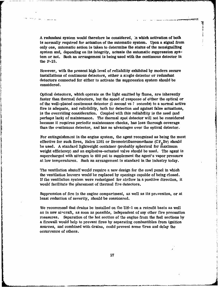
A redundant system would therefore be considered, .n which activation of bothis normally required for actuation of the automatic system. Upon a signal fromonly one, automatic action is taken to determine the status of the nonsignallingsystem and, depending on its integrity, actuate the automatic suppression sys-tem or not. Such an arrangement is being used with the continuous detector inthe F-15.
However, with the present high level of reliability exhibited by modern secureInstallations of continuous detectors, either a single detector or redundantdetectors connected for either to activate the suppression system should be
considered.
Optical detectors, which operate on the light emitted by flame, are inherently
faster than thermal detectors, but the speed of response of either the optical orof the well-placed continuous detector (1 second vs F seconds) to a normal activefire is adequate, and reliability, both for detection and against false actuations,is the overriding consideration. Coupled with this reliability is the need (andperhaps lack) of maintenance. The thermal spot detector will not be consideredbecause it requires periodic maintenance checks, has less thorough coveragethan the cnntinuous detector, and has no advantages over the optical detector.
For extinguishment in the engine system, the agent recognized as being the mosteffective for such fires, Halon 1301 or Bromotrifluoromethane (CF 3 Br) shouldbe used. A standard lightweight container (probably spherical for maximumweight efficiency) and an explosive-actuated valve should be used. The agent issupercharged with nitrogen to 600 psi to supplement the agent's vapor pressureat low temperatures. Such an arrangement is standard in the industry today.
The ventilation shutoff would require a new design for the cowl panel in whichthe ventilation louvers would be replaced by openings capable of being closed.If the ventilation system were redesigned for airflow in a positive direction, itwould facilitate the placement of thermal fire detectors.
Suppression of fire in the engine compartment, as well as its prvvention, or atleast reduction of severity, should be consiaered.
We recommend that drains be installed on the UH-1 on a retrofit basis as wellas in new ai-craft, as soon as possible, independent of any other fire precautionmeasures. Separation of the hot section of the engine from the fuel sections bya firewall would help to prevent fires by separating combustibles from ignitionsources, and combined with drains, could prevent some fires and delay theoccurrence of others.
27

OIL COOLER COMPARTMENT FIRES (KH-1)
This space had one severe fire caused by fuel leaking from the engine compart-ment. This should be eliminated as a future possibility by the installation ofdrains in the engine compartment. However, the oil cooler compartment Is still Ia hazard because it contains a combustible in the oil cooler, and has ignitionsources in the form of a battery and bleed air heat exchanger. While only oneother fire was recorded in this area, the hazard to the aircraft integrity issufficient to warrant consideration.
A separate detection system for this area, probably a smoke detector should beconsidered, since heavy smoke is anticipated prior to actual ignition of oil. Anautomatic oil shutoff would be required, possibly a bypass valve to permit oilflow to continue but to bypass the cooler. A secondary detector should be of thethermal variety, placed to sense a threat to the tanl boom integrity, which wouldautomatically discharge the engine fire extinguisher, through a separate valve,into the oil cooler compartment. It is anticipated that the smoke detector wouldwarn prior to the actual outbreak of fire and permit corrective action by thecrew. Operation of the oil bypass valve could be made manual as an alternateto automatic.
An alternate arrangement could be considered, in which the extinguishant iscontained in a peel-open container and dispersed by an explosive charge activatedby the detector. The container must be installed in the compartment to be pro-tected. Such devices are used In explosion-suppression systems, and provideextremely fast discharge of agent.
ELECTRICAL FIRES
The only effective means of suppressing electrical fires is to first remove theelectrical power. Application of extinguishant may then follow, if combustiblematerials have been ignited. The solution of this problem Is complicated in theUH-1 aircraft because there Is no present correlation between circuit breakersand the location of the electrical equipment they control.
Electrical fires generally are accompanied by generation of considerable smoke,prior to actual ignition of combustibles. The heat from an electrical fire maybe quite small at the onset in proportion to the size of the compartment, makingthermal detection on the compartment level difficult. if the electrical fault iscontained within a piece of equipment, as it probably would be normally, anoptical detector would not be activated. Thus, the choice would be a smokedetector.
28

For an automatic suppression system, a master shutoff would have to be pro-vided for each compartment to enable power to that compartment to be shut off.A fire extinguisher container could be provided for all the inaccessible electricalcompartments, discharging into all of them when a smoke signal is receivedfrom one, since the volume of any one compartment is relatively small, and thevolume of agent required to inert all spaces would require a lighter system thanone of the multivalves to inert compartments singly.
Although each piece of electrical equipment could be provided with its ownthermal cutout, and probably should be, this would not take care of those elec-trical fires that occurred in wiring outside of the equipment.
BATTERY FIRES
Battery fires are actually overheated batteries, which may get hot enough toignite nearby combustibles. The overheating is actually thermal runawaycaused by very rapid charging or overcharging, which in turn is caused by fail-
utre of the charging regulator. 5
The overheating can be stopped only by disconnecting the battery from the charg-ing source. This is best done when overheating or overcharging starts, ratherthan waiting for a fire to result. Therefore, a thermal detector or thermostatmounted on or in the battery which would automatically disconnect the batteryfrom the charging source should be considered.
Thermal monitoring is fire prevention. In the UH-1, extinguishment of a batteryfire would be accomplished by the fire extinguishing means provided for otherhazards in the same compartment. For example: the aft battery compartmentis also the oil coolar compartment; we have already suggested coverage by theengine fire extinguisher, automatically triggered by a smoke detector in thecompartment. This would also cover any fire the battery started.
The forward battery compartment in the UH-1 is part of the forward electricalcompartment and is accessible, for fire fighting, from the cockpit; fires shouldbe extinguished in the forward compartment with a portable fire extinguisheroperated by the crew.
FORWARD ELECTRICAL COMPARTMENT FIRES
These areas, the "chin" area, are open to the cockpit at the pilot's and copilot'sfeet. Any electrical fires occurring in these compartments will be detectedpromptly by the crew through their sense of smell. With identification of cir-cuit breakers protecting equipment in these compartments, the crew can manually
29

pull the proper breakers. Extinguishing can be accomplished with the cabinportable Halon fire extinguisher by putting the discharge nozzle at the compart-ment opening at the pilot's or copilot's feet.
If desired, automatic suppression could be used. A smoke detector could sensethe fire and would operate an electrical disconnect for the compartment, includ-ing the battery, and actuate a small fire extinguisher container. Halon 1301(CF 3Br) is the most effective extinguishing agent. The quantity would be small,and While the toxic products created by the reaction of the Halon on the firecould enter the cabin, the volume would be too small to be harmful to the crew.
AFT PYLON FIRES (CH-47)
An automatic fire suppression system has already been designed by Boeing-Vertol for this area and submitted to the Army. It consists of three Halon ex-.tinguisher containers each covering a compartment in the aft pylon. Eachextinguisher is automatically triggered by any one of several overlapping opticaldetectors.
However, there should be a physical barrier in the tunnel between the engine nosegearbox and the combining transmission to prevent the propagation of fire origi-nating in the nose gearbox into the aft pylon. The engine fire extinguishing anddetection systems should be extended to the nose gearbox area.
AFT CABIN FIRES (CH-47)
This area was the scene of many in-flight fires, fed from the complex of fueland hydraulic fluid lines in the area. This area of the cabin is accessible dur-ing flight, and is the station for the crew chief.
Visual fire detection by the cabin occupants would, therefore, be sufficient, andextinguishment of any fire would be best handled manually by the crew with atleast two portable fire extinguishers stored nearby. Halon should be used forthe extinguishing agent. The use of dry chemical for its "throwing power", andfor the protection the cloud of powder gives the operator in shielding him fromthe heat of the fire, should be considered. However, dry chemical poses acleanup and corrosion problem, and so its use should be held in reserve.
These cabin fires can be disastrously severe, and so the crew should be fur-nished with mrre fire fighting aids than just the extinguishers. First, should bethe provision of sufficient shutoff valves, plainly marked for emergency use, tostop the flow of combustibles. And since the valve may be hot from the fire,protective gauntlets should be provided.
30

The normal ventilation in the CH-47 cabin is from the rear forward. This ex-poses the occupants of the cabin to the hot gases from a fire in the aft cabin.Fortunately, this ventilation exits through the cargo door just aft of the cockpit,so the flight crew can be isolated. This ventilation should be reversed. If thiscannot be done, then a fire curtain to prevent the spread of the fire productsforward, together with additional ventilation openings in the cabin walls forwardof the fire curtain, should be provided. Cargo stowage would have to allow fordeployment of the fire curtain.
FUEL CELL FIRES
Fuel cell fires that occurred in the UH-1 were all caused by hostile fire. Themechanism of the fires seemed to be penetration of the fuel cell by the round,followed by ignition of leaking fuel which burned outside the fuel cell. However,three fuel cell explosions occurred as a result of hits.
Preventing fuel cell explosions, either (1) by using reticulated polyurethane foam,(2) by maintaining an inert atmosphere in the fuel cells, or (3) by providing anautomatic explosion suppression system in the fuel cells should be considered.
Alternate (1) would probably involve the least weight penalty, particularly if themethod is used of dividing the cell with foam into explosion-manageable volumes,rather than filling the entire cell. Alternate (2) would involve carrying a con-siderable quantity of nitrogen on board, plus the complexity of the system formetering it into the fuel cells as required. It would also involve fitting the fuelcell vents with check valves to prevent in-breathing. Alternate (3) is madecomplex by the shape and number of fuel cells in the UH-1.
The UH-1 is being fitted with crash-resistant fuel cells that are also self-sealingfor .50 caliber hits. Although these fuel cells will have little effect on the possi-bility of fuel cell explosions, they should materially reduce the occurrence ofthose fuel cell fires where the fuel burned outside the cell from puncture leaks.
Should the self-sealing cf the fuel cells not be 100% effective, however, a firesuppression system should be used for the spaces surrounding the fuel cells.The continuous detector lends itself to installation in the spaces surrounding thefuel cells, and upon actuation by fire, would automatically discharge a fire ex-tinguishant into all the void spaces surrounding the fuel cells. The extinguishantmost suitable would be Halon 1301. The discharge system would require outletsin each general void area.
The best container would probably be the usual sphere, superpressurized withnitrogen and fitted with an explosively actuated valve. The discharge systemwould be a system of tubes conducting the extinguishant to each major void area,where the gaseous agent would rapidly spread into all its subdivisions.
31

The spaces would remain inert for some prolonged period, so re-ignition by asubsequent hit would be unlikely; therefore, a single-shot extinguishing systemwould provide adequate protection.
ARMAMENT AND PAYLOAD (CARGO) FIRES
Built-in, automatic fire suppression systems for such fires would not be feasible,unless the aircraft were designed for a particular payload for which a specificsystem could be drigned.
However, some fire precautions are indicated. The jettison mechanism forrockets should be improved to provide positive means of jettisoning when struckand ignited by gunfire, even if the mechanism should be damaged by such gunfire.If the rockets cannot be jettisoned, then the aircraft should be shielded fromserious damage from the burning rocket.
A number of incidents have occurred in which payload burned inside the aircraft.Since the crew is present, they can be an effective fire-fighting force if provided
with the necessary tools. Some tool should be provided, such as tongs or ashovel, to pick up a burning flare or smoke grenade and dispose of it overboard.Protective clothing may be necessary, particularly gloves and goggles.
An adequate number of portable fire extinguishers should be provided, and theyshould be placed where they can easily be reached in an emergency. At least twoHalon portable for the UH-1 should be provided, plus a dry chemical extinguisherfor "emergency" use, the dry chemical having better "throwing" power and pro-viding a protective cloud to the operator.
If any special cargo or armamei t is taken aboard, special fire protection shouldbe provided in the event of emergency. For example, if a load of magnesiumflares is carried, a special portable fire extinguisher containing the special drychemical agent that will extinguish magnesium fires should be carried. Jettison-ing such cargo should be considered first, and the necessary precautions shouldbe taken.
32

AUTOMATIC DETECTION AND SUPPRESSION SYSTEMS REQUIREMENTS
A Helicopter Fire Detection and Automatic Suppression System shall be designedto sense a fire and react immediately to extinguish the burning. It shall simul-taneously initiate action necessary to prevent recurrence.
This preventive action may consist of:1. Cutting off fuel2. Removing ignition source3. Excluding oxygen
a. Stopping or reducing airflowb. Inerting compartments
The system will provide the pilot a warning light indicating that an alarm con-dition exists. Further indication may be provided that systems functions havebeen performed. The initial light shall be self-clearing when the fire has beenextinguished.
The system must also incorporate a test feature which will, when activated,
indicate system integrity.
Particular emphasis must be placed on providing a system which will respondonly to fire. It shall not respond to:
Power supply variations including: voltage spikes, frequency shifts,polarity reverses or momentarycircuit faults
MoistureArtificial LightSunlightElectromagnetic RadiationCircuit Component Failure
The system must maintain its integrity and function properly under and afterconditions of load and environment imposed by helicopter service. It must besimple to maintain and not interfere with maintenance of other helicopter com-ponents. A Helicopter Fire Detection and Automatic Suppression System willconsist of the following components.
1. A fire detecting system of the appropriate type for the space being pro-tected. This shall be selected from the thermal continuous, radiationsensing, or smoke detection types, consistent with existing specifica-tions and with modifications as described in subsequent paragraphs.
33

2. A fire extinguishing system of the high rate discharge or explosive
dispersion type, which is also further detailed in subsequent paragraphs.
3. An appropriate cockpit display to indicate functioning of the system.
4. A system integrity test circuit.
5. A detector-extinguisher interface unit, capable of providing firing cur-rent to the extinguisher when activated by the detector output. This unitmay also be capable of switching power for other suppression functionsas required for a specific installation; to shut off valves, cut off airflow,etc. This device may also integrate the system test and display functions.
DESIGN CRITERIA
Continuous Fire Detector (Thermal)
Continuous detectors shall be designed and installed in accordance with applic-able portione of Military Specification MIL-F-7872C, "Fire and OverheatWarning Systems, Continuous, Aircraft, Test and Installation of:"
Radiation Sersing (Flame) Detectors
Radiation sensing detectors shall be designed and installed as required byMilitary Specification MIL-F-23447, "Fire Warning Systems, Aircraft RadiationSensing Type: Test and Installation of:" with the following exception:
Paragraph 3.4.2. Flame Detector Response. Instead of 5 seconds, aresponse of 2 seconds will be required. (This is within the capability ofexisting equipment.) Paragraphs 3.4.7 through 3.4.9 dealing in warninglights are waived for use in automatic suppression systems.
Smoke Detectors
Smoke detectors for use in the Helicopter Fire Detectors and Automatic Sup-pression System shall comply with Military Specification MIL-D-27729A,"Detecting Systems; Flame and Smoke, Aircraft and Aerospace Vehicle,General Performance, Installation and Test of" as applicable to smokedetectors.
34

/IFire Suppression Systems
Fire suppression systems shall be designed to provide agent quantities con-sistent with Military Specification MIL-E-22285, "Extinguishing System, Fire,Aircraft High Rate Discharge Type, Installation and Test of:" except that ininstances where reflash following initial extinguishing is likely, the concentra-tion must be maintained for a longer period.
Applicable portions of MIL-F-25648, "Fire and Explosion Suppression Units,Aircraft Fuel Tank and Tank Cavity, General Specifications for", will be thegoverning specification for capsule type extinguishers, with the basic exceptionthat the agent will be Dibromotetrafluoroethane (CF 2Br-CF2 Br, Halon 2402).Conventional extinguishing containers will conform to MIL-F-22284A, "MilitarySpecification, Container, Aircraft Fire Extinguishing System, Bromotrifluoro-methane CF 3 Br (Halon 1301)."
Detector Extinguisher Interface Unit Design Criteria
This device will monitor the detector output (2 amps resistive). Upon receivinga signal indicating that a fire has started, it will provide indication to the pilotand close the circuit (10 amp), causing discharge of the fire extinguisher. Sim-ultaneous with this action, circuits capable of controlling additional functionswill be activated. A signal of this sequence will also be available for display.
A means will be provided to establish continuity throughout the circuit such that
on command the detector will function, with suitable switching so that the testcurrent through the fire extinguisher cartridge will be limited to 0.5 amp.
If the detector functions and all circuits from the detector to the extinguisherand through the cartridge are continuous, the system test light will illuminate.The test light is not to extinguish if the relay which switches the cartridge tothe current-limited source remains in that position after test.
35

SYSTEM APPROACH
Having arrived at a combination of hardware which can be used in an automaticdetection and suppression system, there are a number of system arrangementsto be considered.
In the simplest arrangement, a detector output triggers an extinguisher such thatpresentation of stimulus to the detector results in discharge of the agent.
DET. ET
In conventional, manually Initiated aircraft extinguishing systems, it is usual toprovide a second or reserve "shot" of extinguishant, if for some reason, the firstis not effective. The same could be accomplished in a fully automatic system byusing a time delay circuit such that if the detector had not cleared within a giventime period, the reserve container would be discharged. This could be arrangedso that clearing of the fire signal after the first discharge would cancel the timedelay so that the reserve shot would be fired immediately upon receipt of asecond signal.
E cDetector Ext. #1
TimeDelay
Ext. #2
The purpose of an automatically initiated fire suppression system is to gain thetime normally lost by manual initiation, since time is critical in helicopter in-flight fires. Reliability of detection becomes important, therefore, to assure thatfires are promptly detected and the extinguishing initiated. Redundancy in detec-tors is commonly used to achieve this reliability, the redundant detectors beingarranged in the "either-or" mode, so that either detector may Initiate the firesuppression sequence.
'6

( Detector I
"Ext. "OR"Detector,
2Reliability to detect = 2 Ret - %~et2 (•Ryet.)
Reliability against false detection = RDet2 (-< RDet.)
However, since the automatic system removes some of the aircraft shutdownprocedures from crew control, the possibility of the automat.c t'ystem triggeringinadvertently becomes of concern, and the "OR" arrangemen• oi "e~ectors in-creases this possibility. From the standpoint of preventions 117 JInadvertent actua-tion, an "AND" mode of redundant detector operation woulk '- preferable, inwhich the activation of both detectors would be required to initiate the fire sup-pression sequence. The ad ,antage of this arrangement would be completelynegated in the event of the failure of one detector.
Dtector Deteto-"-N- Ext."A "
2Reliabilit*y to detect = Ret (• Ret )
Reliability against false detection =2 RDet - RDet2 R Det)
Reliable as detectors have become, the "OR" arrangement is not recommendedfor an automatic system where flight capability is in any way reduced. And adetector failure in a strictly "AND" arrangement could be calamitous in theevent of fire occurrence.
The latest advance in detector system reliability technology which could be ex-tremely valuable in helicopters is the use of dual detectors arranged Iv the "AND"mode of operation, but where activation of only one detector automaticallytriggers an interrogation (test) of the other detector. If the other detector is
37

F
faulty, the fire suppression sequence is initiated. If, on the other hand, theother detector is operative, the signal from the first is presumed to be false,and the fire suppression sequence is not initiated. Such an arrangement givesthe favorable reliabilities of both the AND or OR modes, with a delay in initia-tion in the event of failure of one detector of less than 20 milliseconds.
Although the automatic self-interrogating system has been applied only to redun-dant continuous systems, there is no limitation which would prevent its applica-tion to other types of sensors, or even to a combination of different types ofsensors in a mixed system.
One of the secondary considerations, regardless of system type pursued, iscockpit display. It is recommended that the minimum to be considered is indi-cation to warn the pilot that his automatic system has functioned. This signalcould be transmitted when the sensor triggers the signal firing the container.An additional signal could be presented from a pressure switch in the line indi-cating that the extinguisher had functioned. When the fire light cleared, follow-ing this signal, it would indicate a successful extinguishment of a fire.
If automatic systems are incorporated in more than one space, each space
should have an indicator since different courses of action might be indicated forthe pilot, depending on the space involved. Whereas he might elect to continueto his base after the cutoff of an electronic compartment, he would desire toset down rapidly following engine fire in a single-engine craft.
In considerirg automatic suppression, cutting the engine of a single-engine craftpresents as severe a hazard as fire. It will therefore be necessary to allow con-tinued flow of ti'el to the engine and possibly to the fire. We may therefore, fol-lowing tne Initial extinction of the fire, continue to present fuel to a source ofignition which has not been removed. It is therefore desirable to maintain theagent concentration in the space as long as possible after first application. Thiscan be accomplished by cutting off airflow or by continually adding agent.
The minimum design concentration for inerting JP-4 as set forth in NFPAStandard on Halogenated Fire Extinguisher Systems is 6.6% by volume. Afterextinction of the Iz'e, it would be necessary to add .026 lb of agent for eachcubic foot of air flowing into the compartment. If we assume a moderate air-flow of 1000 cfm and desire to maintain the inert atmosphere for 5 minutes, therequired agent weight would be 130 pounds. This quantity of agent would requirea storage container of approximately 3000 cubic inches (an 18-inch-diametersphere) with a container weight of at least 29 pounds.
A system to maintain an inert atmosphere in a compartment having airflow of1000 cfm would have the following weights:
38
A...e4

Agent 130 lbContainer assembly 29 lbTubing 30 ft of 1/4 x.012 In. 1 lbMounting hardware 5 lb
This weight can be reduced by allowing a shorter period of time for the pilot toget down or by reducing the compartment airflow or by a combination of both.
In view of the high weight penalty of maintaining an inert atmosphere with evenmoderate airflow, closing the cowl openings as part of the suppression pro-cedure is recommended. There are two sources of compartment airflow, thenormal ventilating air and the compressor interstage bleed air.
One reason for the amount of open area in the engine cowl of craft using thesesmall turbines is that the engine at speeds below flight idle or during periodsof acceleration unloads by dumping interstage bleed air. Following a suppres-sion action, it is recommended that the engine be operated above flight Idle andas much as possible without speed changes.
39

SYSTEM DESIGNS
The system designs discussed previously are illustrated in Figures 2 through 18
for each of the hazard spaces to be protected. These systems are listed along
with estimated cost and weight in Table II.
TABLE III. COST AND WEIGHT SUMMARY
Space Description Weight (lb) Cost ($)
Engine Single Thermal, Single Ext. 7.33 531
Engine Single Thermal, Dual Ext. 13.12 (86
Engine Single Optical, Single Ext. 7.29 690
Engine Single Optical, Dual Ext. 13.08 945
Engine Dual Thermal, Single Ext. 8.68 978
Engine Dual Thermal, Dual Ext. 14.47 1, 233
Engine Dual Optical, Single Ext. 8.19 1,115
Engine Dual Optical, Dual Ext. 13.88 1,390
Oil Cooler Single Optical, Single Ext. 7.29 690
Oil Cooler Dual Optical, Single Ext. 8.19 1,135
Oil Cooler Single Optical, Dual Ext. 13.08 945
Oil Cooler Dual Optical, Dual Ext. 13.98 1,390
Electronics Single Smoke, No Ext. .98 254
Electronics Single Smoke, Single Ext. 6.64 544
Fuel Cells Area Single Thermal, Single Ext. 7.33 786
Fuel Cells (5) Explosion Suppression 15..50 2,550
Fuel Cells (5) Nitrogen Inerting System
Fuel Cells Reticulated Foam, 50% void 23.25 300
40

The following system designs consider only individual systems, each protectinga single space. Each system design provides a single-shot, or an alternatedouble-shot (main and reserve), extinguishing system.
It is recognized that the weight of several double-shot systems could be pro-hibitive. However, any given space can be protected to the same degree of Ireliability by using a single 'to-shot system to cover two spaces. Thus, a •
fire in either space would have the benefit of a main anw reserve shot. Onlyin the event of a fire occurring in each space would a single shot be providedfor each. This would be an unlikely occurrence if the spaces to be joined by anextinguisher system avoid the potential of a fire spreading from one to another.
For a two-shot system, a second discharge valve is added to each container,and the containers are arranged as shown in Figure 1. The two-way checkvalve prevents the agent from the reserve shot entering the previously firedbut now empty first-shot container.
The weight increase for such a system is 1.0 lb per container for the additionalvalve, and .14 lb for each tee, making a total increase of 2.28 lb. This maybe compared with the 5.4 lb for the smallest single outlet container.
AUTOMATIC FIRE DETECTION AND SUPPRESSION SYSTEM - ENGJNESPACE (See Figure 2)
Single Thermal Detector, Single Extinguisher
The sensor for this type system consists of continuous sensing elements routedthrough the engine space in locations where the heat flow, in the event of a fire,impinges on some portion of the elements. The control unit associated withthese elements responds to a fire by initiating the fire extinguishing sequence.
The interfae unit accepts the detector fire signal and directs the 10-amp firingcurrent to the extinguisher. The extinguisher is a container of Halon 1301(CF 3 Br), pressurized with nitrogen gas to 600 psi to provide a high rate dis-charge (HRD) in accordance with MIL-C-22284.
Since the fuel flow cannot be shut off without shutting off the engine, the onlyalternate is to shut off the airflow into the compartment. This is accomplirihedby redesigning the engine vents so that they may be closed. The detection sys-tem, through the interface unit, provides the power to close the vents simul-taneously with discharging the extinguisher. With air ventilation stopped orgreatly reduced, the extinguishant can maintain an inert atmosphere in the enginecompartment and thus prevent the fire restriking.
41

Dual OutletContainer (2)
Signal from Signal fromSpace 2 Space 1Interface Unit Interface Delay Unit
Firing Pressure Switch (2)
Agent to CartridgeAgent toSpace 2 Space 1
A
Two-WayCheck Valve (2)
Signal from Signal from
Space 2 Space I
Interface Delay Unit Interface Unit
Figure 1. Automatic Firt: Detection and SuppressionTwo-Space Main and Reserve ExtinguishingSystem.
42

t"
VentilationShutoff
Vent Closed
Light
FireEgn Detect
Engine Light
C o p r m n E xtinguisher
I Control a@ DischargeIU:~t jLighthI Systemt
I Sensing Test Light
Element - i
I Continuous L interface
I I
T Test- J- - - Switch
Extinguisher
PressureSwitch
Figure 2. Automatic Fire Detection and Suppression System,
Engine Space - Single Thermal Detector,Single Extinguisher.
43

With ventilation shut off, engine cooling will be impaired, but operating underreduced power, it will be possible to continue flight until a landing spot can beselected.
Indication of the suppression action must be provided to the crew so that theymay adjust their flight operations accordingly. A light will be energized by theinterface unit to indicate fire detection. Another light will be energized by apressure switch in the extinguisher outlet line to indicate extinguisher discharge.Another light is provided, operated by the vent itself, to indicate the vent isclosed. This latter is valuable to prevent operation of the aircraft with thevents inadvertently closed.
A test switch is provided in the cockpit to test the integrity of the system.Operating the test switch checks the functioning of the sensor control units andthe interface unit and the continuity of the wires through the extinguisher dis-charge cartridge. If the test light illuminates in test, it indicates the systemis "go". A transfer relay in the interface unit switches tLe extinguisher car-tridge to a test current source that is limited to 0.5 ampere, well below thecartridge firing threshold. If the transfer relay "hangs up" on test, the testlight will not extinguish after test, indicating a system malfunction.
AUTOMATIC FIRE DETECTION AND SUPPRESSION SYSTEM - ENGINESPACE (See Figure 3)
Single Thermal, Dual Extinguisher
This system is similar to the single system except that this system provides asecond or reserve shot of extinguishant. A time delay circuit is connected tothe reserve contabier.
The container firing circuit will fire one bottle immediately. It will also initiate
a time delay mechanism, and if the alairm has not cleared within 45 seconds,fire the second container. If the alarm has cleared the second container willnot fire at the completion of the delay sequence but will then be ready for imme-diate discharge upon receipt of a second signal.
AUTOMATIC FIRE DETECTION AND SUPPRESSION SYSTEM - ENGINESPACE (See Figure 4)
44

r[
Ventilation
Shutoff
Vent ClosedLight
Fire""DetectEngine Light
Compartment Lig
- MainSr- Control Unit Extinguisher
" Cnto UitFired Light
- ReserveExtinguisher
Continuous [Interface Fired Light
Sensing Unit with a System Test
Element Delay Light
Test,,Maita
Extinguisher.Pressutre Switch
ReserveExtinguisher
Pressure Switch
Figure 3. Automatic Fire Detection and Suppression System,Engine Space - Single Thermal Detector,Main and Reserve Extinguishers.
45

L •"~
VentilationShutoff
Vent ClosedLightFire
Engine DetectCompartment Light
Extinguishera Discharge
Co[Untrl Light
Unit SystemTest Light
FI ._InterfaceI [ Unit
Sensor (4) gsFExtinguisher
PressureSwitch
Figure 4. Automatic Fire Detection and Suppression System,Engine Space - Single Optical Detector,Single Extinguisher.
46

Single Optical Detector, Single Extinguishe
This system employs four optical sensors installed in the engine compartment,mounted near the deck, one in each of the four corners and pointed toward theengine and upward. Thus, any fire occurring in the compartment will be in theview of at least two of the sensors on one side of the engine.
When a fire situation occurs, the detecting system signal triggers the fire ex-tinguishing sequence.
The interface unit also activates the airflow shutoff system, provides necessaryindication to the crew, and incorporates system integrity tests.
AUTOMATIC FIRE DETECTION AND SUPPRESSION SYSTEM - ENGINE
SPACE (See Figure 5)
Single Optical, Dual Extinguisher
This system adds a second or reserve shot of extinguishant to the single optical,single extinguisher system. A time delay circuit is employed to the reservecontainer.
The container firing circuit will fire one bottle immediately. It will also initiatea time delay mechanism, and If the alarm has not cleared within 45 seconds,fire the other container. If the alarm is cleared the container will not fire at
the completion of the delay sequence, but will then be ready for immediate dis-charge upon receipt of a second signal.
AUTOMATIC FIRE DETECTION AND SUPPRESSION SYSTEM - ENGINESPACE (See Figure 6)
Dual Thermal Sensors, Self-Interrogating, Single Extinguisher
Dual sensing elements are located in the engine compartment to intercept anyflame paths in the event of fire. Control circuitry upon signal from only onesensor would take automatic action to determine the status of the nonrespondingsystem, and depending on its status, actuate the automatic suppression systemor not.
If the tested sensor is functioning properly, the first signal must then be false,and the fire extinguishing sequence is not initiated. However, if the second
47

VentilationShutoff
Vent ClosedLight
Fireo Detect
Engine LightCompartment
MainF 1Control Unit Extinguisher
I I •Fired LightReserve
. Extinguisher-n aFired Light
I~~fc UiwihSstemI I Delay Test Light Ui ih ---
I II I
Mainoptical-"Extinguisher
icalIn -te :rfac e S yst em
Sensor (4) Preu rei
SReserveExtinguisher
Pressure Switch
Figure 5. Automatic Fire Detection and Suppression System,Engine Space - Single Optical Detectors, Mainand Reserve Extinguishers.
48

VentilationShutoff
Light
FireEngine - Detect
Compartment Light
t Extinguis herInterrogating Dtsch'.'rgeControl Unit [ LightDua I _.System
[1 [ Sensing [Test Light| Elements J11! Continuous Interface
Unit
Tstj ~Switch
ExtinguisherMaintenanceTest Switch Pressure
Switch
Figure 6. Automatic Fire Detection and Suppression System,Engine Space - Dual Thermal Detectors, Self-Interrogating, Single Extinguisher.
49

sensor fails the test, the first signal must then be considered true, aad thefire extinguishing sequence is triggered.
With the self-interrogating circuit, the cockpit integrity test will test good ifonly one sensor in each control circuit is operative, thus permitting dispatchof the aircraft, if necessary, since that provides a minimum operating system.A second test switch is provided to maintenance action which tests all functionsof the detection system.
The system beyond this point is identical with previously discussed enginespace systems.
AUTOMATIC FIRE DETECTION AND SUPPRESSION SYSTEM - ENGINESPACE (See Figure 7)
Dual Thermal Sensors, Self-Interrogating, Dual Extinguisher
This system adds a second or reserve shot of extinguishant to the dual thermalsensors self-interrogating, single extinguisher system. A time delay circuit isemployed to the reserve container.
The container firing circuit will fire one bottle immediately. It will also initiatea time delay mechanism, and if the alarm has not cleared within 45 seconds,fire the other container. If the alarm is cleared, the container will not fire atthe completion of the delay sequence but will then be ready for immediate dis-charge upon receipt of a second signal.
AUTOMATIC FIRE DETECTION AND SUPPRESSION SYSTEM - ENGINESPACE (See Figure 8)
Dual Optical Sensors, Self-Interrogating, Single Extinguisher
This system differs from those previously discussed only in that it employs fouroptical sensors installed in the engine compartment, mounted near the deck, onein each of the four corners and pointed toward the engine and upward. Thus, anyfire occurring in the compartment will b in view of at least two sensors on oneside of the engine. With the two sensors pointing in approximately oppositedirections, it is unlikely that any stray light which might actuate one detectorwould actuate both. The two sensors on one side will be connected to one con-trol unit, while the two sensors on the other side will be connected to anothercontrol unit.
50
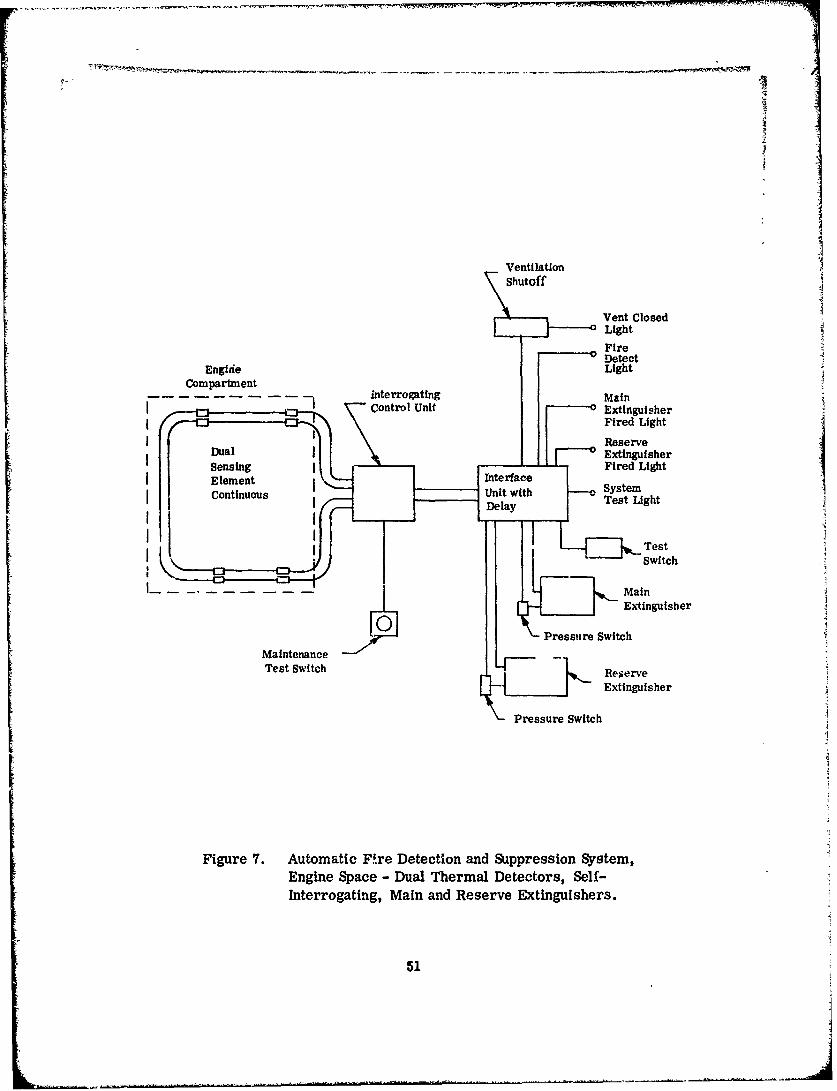
17
VentlationShutoff
Vent ClosedLight
FireDetect
Engide LightCompartment
interrogating MainControl Unit 0 Extinguisher
Fired Light
ReserveSDual ExtinguisherSensing eFired Light[ Element e SystemConinuusUnit with Tes Light
Continuous [ ~Delay [ Ts ~h
[• Test
Test Switch R_ Switch
Extinguisher
Pressure SwitchMaintenanceTest Switch "•• Reierve
•__ Extinguisher
•-Pressure Switch
Figure 7. Automatic F~re Detection and Suppression System,Engine Space - Dual Thermal Detectors, Self-Interrogating, Main and Reserve Extinguishers.
51
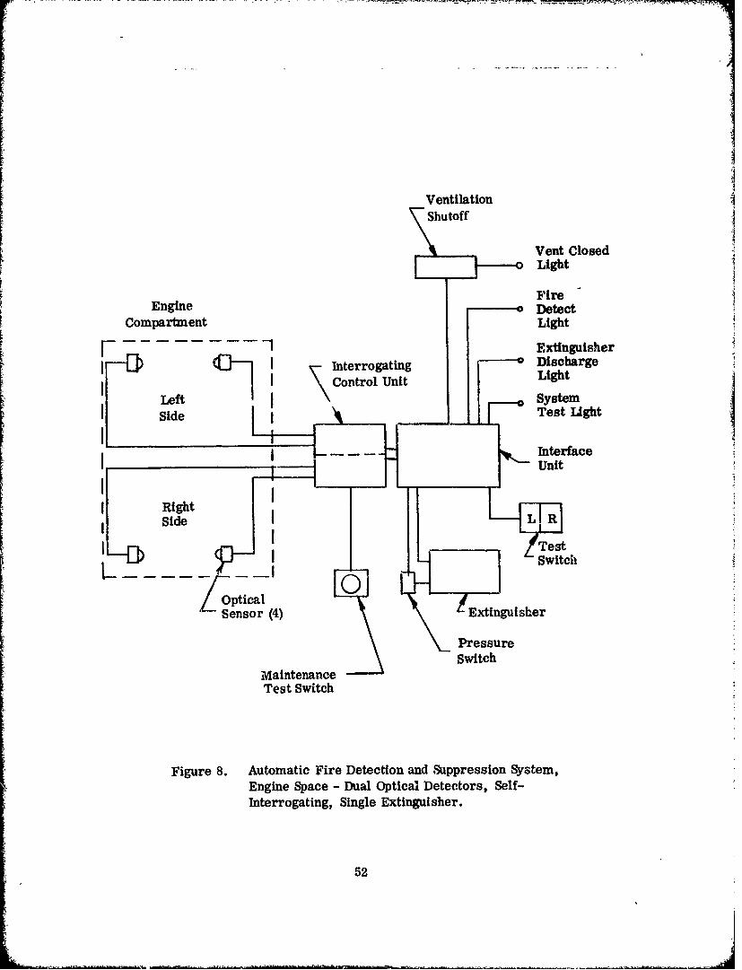
VentilationShutoff
Vent ClosedLight
FireEngine Detect
Compartment Light] Extinguisher
01 1 \Interrogating - DischargeCI ontrol Unit Light
Left SystemSide Test Light
InterfaceUnit
Side L R
LD[' Switch
Optical
Sensor (4) Extingusher
Pressureswitch
MaintenanceTest Switch
Figure 8. Automatic Fire Detection and Suppression System,Engine Space - Dual Optical Detectors, Self-Interrogating, Single Extinguisher.
52
?J

Either control unit (a fire on either side of the engine) may initiate the extin-
guishing sequence. Normally, both sensors would have to activate the controlunit to initiate the extinguishing sequence, but upon receipt of a signal from Ionly one sensor, the other sensor is automatically interrogated (tested).
If the tested sensor is functioning properly, the first signal must then be false,and the fire extinguishing sequence is not initiated. However, if the second Isensor fails the test, the first signal must then be considered true, and thefire extinguishing sequence is triggered.
With the self-interrogating circuit, the cockpit integrity test will test good ifonly one sensor in each control circuit is operative, thus permitting dispatch ofthe ai.rcraft, if necessary, since that provides a minimum operating system.A second test switch is provided for maintenance action which tests all functionsof the detection system.
AUTOMATIC FIRE DETECTION AND SUPPRESSION SYSTEM - ENGINESPACE (See Figure 9)
Dual Optical Sensors, Self-.Interrogating, Dual Extinguishers
This system adds a second or reserve shot of extinguishant to the dual opticalself-interrogating, single extinguisher system. A time delay circuit is employedto the reserve container.
The container firing circuit will fire one bottle immediately. It will also initiatea time delay mechanism, and if the alarm has not cleared within 45 seconds,fire the other container. If the alarm is cleared the container will not fire atthe completion of the delay sequence, but will then be ready for immediate dis-
charge upon receipt of a second signal.
AUTOMATIC FIRE DETECTION AND SUPPRESSION SYSTEM OIL - COOLERCOMPARTMENT (See Figure 10)
This system consists of a pair of optical sensors, each of which will include theoil cooler, heater, batuery rack and the floor of the compartment in its field ofview. Either sensor, through the control unit and interface unit, will automat-ically actuate the fire extinguisher. The fire extinguisher will be a recharge-able container of Halon 1301 (CF 3 Br), pressurized with nitrogen gas to 600 psito give a high rate discharge (HRD) in accordance with MIL-C-22284.
53

VentilaticnShutoff
Vent ClosedLight
FireDetect
Engine LightCompartment main
-Interrogating ExtinguisherControl Unit Fired Light
ReserveSExtinguisher
Fired LightSInterface
. Unit with - SystemPeslay Test Light
TestSwftch
MainExtinguisher
OpticalSensor (4) Pressure Switch
Reserve
Maintenance Extinguisher
Test SwitchPressure Switch
Figure 9. Automatic Fire Detection and Suppression System,Engine Space - Dual Optical Detectors, Self-Interrogating, Main and Reserve Extinguishers.
54

Oil BypassValve
ValveClosedLight
Oil Cooler FireCompartment DetectS~Light
F1ExtinguisherSI o•ontrolUnit _0 Discharge
I Light
I ~systemjInterface Test LightI I Unit
STest-- Op[ca Switch
I Sensor (2) I Oil
L ExtinguisherPan Shutoff
Pressure Switch
Figure 10. Automatic Fire Detection and Suppression System,Oil Cooler Compartment - Single Optical Detectorand Extinguisher.
55

An off bypass valve, installed across the oil cooler, will be activated simul-tanecusly to divert oil from the oil cooler compartment, which presumably willbe the combustible. Bypassing the oil, instead of shutting down the flow, willpermit continued operation of the engine for a period of time. The oil coolerfan will also be shut down by thq interface unit upon the fire signal, thus reduc-ing the compartment ventilation to a very small rate. This will allow the ex-tinguishant to maintain an inert atmosphere and prevent restriking of the fire.
Indications to the cockpit will be a light controlled by the interface unit showingactivation of the system, and a light controlled by a pressure switch in the ex-tinguishing container outlet showing discharge of the extinguishant. Thus, thecrew is aware r f a fire breakout, and aware that the extinguishant has been dis-charged. If the fire is extinguished pr'omptly, the detector will reset and extin-guish the fire alarm light, advising the crew the fire is under control. Shouldthe first discharge be ineffective, a delay circuit in h.*. interface unit dischargesa reserve container of extinguishant which will be indicated in the cockpit bya second "extinguisher fred" light. Again, if the fire is extinguished, the alarmlight will go out. By thes& indicators, the crew will also be advised that the oilis now bypassing the oil cooler, so that it may be considered in engine operationand continued flight.
A test circuit is provided, actunted by a switch in the cockpit, which checks thefunctioning of the detectors, interface unit, and continuity of wiring to andthrough the extinguisher cartridge. A light is furnished which, when illuminatedupon test, assures the system integrity. A transfer relay in the interface unittransfers the extinguisher cartridge for the continuity test to a source of currentlimited to 0.5 ampere - not enough to fire the cartridge. If the transfer relay"hangs up" after the test, the test light will not extinguish, indicating a mal-functioning system.
ALTERNATE (See Figure 11)
To provide reliability beyond that possible with a single detection system, thisalternate provides that both sensors normally be activated by fire to initiate theextinguishing sequence. However, a control unit is provided that upon receipt ofa signal from only one sensor automatically interrogates (tests) the second sen-sor. If the second sensor tests good, the signal received from the first is treatedas false. If, however, the second sensor fails to test, the extingtuishing sequenceis initiated.
The cockpit test for this alternate will give a "go" signal if only one of the redun-dant sensors is operative, thus permitting dispatch of the aircraft. A secondtest switch is provided for use by the maintenance crew that tests all the func-tions of the detection system.
56

Oil Bypass
Valve
Valve--o Closed
Light
Oil Cooler FireC r DetectCompartment Light
I • [ Interrogating• Con -"trolCotl IUnit Extinguisher
I Control Uni- Discharge
Light ISystem
I I• [Interface - SsteIne Test Light
TestSwitch
Optical "ExtinguisherSensors (2)
_j- OilCoolerFan Shutoff Pressure Switch
MaintenanceTest Switch
Figure 11. Automatic Fire Detection an( Suppression System,Oil Cooler Compartment - Dual Optical Detectors,Self-Interrogating, Single Extinguisher.
57

ALTERNATES 'See Figures 12 and 13)
This alternate provides a two-shot, main and reserve extinguisher for either ofthe two preceding detector systems.
The container firing circuit will fire one bottle immediately. It will also initiatea time delay mechanism, and if the alarm has not cleared within 45 seconds,fire the other container. If the alarm is cleared the container will not fire atthe completion of the delay sequence, but will then be ready for immediate dis-charge upon receipt of a second signal.
AUTOMATIC FIRE DETECTION AND SUPPRESSION SYSTEM (See Figure 14)
Electrical Equipment Compartment
In electrical compartments, fires start as overheated electrical components.Smoke is generated as insulation chars long before flame occurs, or beforesufficient heat is generated to raise the compartment temperature enough totrigger a thermal alarm. Thus, this system will use smoke detectors. Thesmoke detector will be placed in the path of compartment airflow at its outlet.The smoke detector, through its control unit, will activate the interface unit,which in turn will interrupt all power to that compartment. This will require amaster electrical shutoff device for each separate electrical compartment to be
protected. It will be necessary to alert the crew to this shutdown. This will beaccomplished by illuminating a warning light in the cockpit.
The integrity of the system can be tested from the cockpit by actuating a testswitch which functionally tests the smoke sensor, checks the operation of thecontrol unit and interface unit, and checks the continuity of the wire leading tothe electrical shutoff device. A transfer relay in the interface unit transfersthe shutoff device to a source of test current that is limited to a value wellbelow the operating threshold of the device. Should the transfer relay "hang up"on release of the test switch, the tost light will not extinguish, indicating a mal-functioning system.
58

Oil BypassValve
ValveClosedLight
Oil Cooler FireCompartment DetectLight
r -- jControl Unit Extinguisher
I Dischargej LightI Reserve
I IJ , .Interface ,L iy ste
-Unit Test Light
Switch _Test
Optical -Sensors (2) ReserveL. .--..- •jOil Coolet erv
"-Fan Shutoff Delay Extinguisher
Extinguisher
Pressure Switch
Figure 12. Autormatic Fire Detection and Suppression System,Oil Cooler Compartment - Single Optical Detector,Main and Reserve Extinguishers.
59

Oil BypassValve
ValveClosedLight
Fire
Oil Cooler DetectCompartment Light
F -. -! hfInterrogating Extinguisher
Control Unit °Discharge
J • Reserve[-----DischargeJ 1 1 Light
J [• Interface _.oSystem
SUnit Test Light
J Pressurel (• • oolr lay•.Swiwttc
J J I •.Test
IOptical -I Sensors (2)
Oil ColerReserveFan Shutoff Extinguisher
EnMaintenance
Pressure Switch
Figure 13. Automatic Fire Detection and Suppression System,Oil Cooler Compartment - Dual Optical Detectors,Self-Interrogating, Main and Reserve Extinguishers.
60

CompartmentPower-Off Switch
Smoke SmokeDetector •CoDetectorDetectorLight
Cntrol Unit
oSystemTest Light
STest
Switch
Figure 14. Automatic Fire Detection and SuppressionElectrical Equipment SpaceSmoke Detector and Power Shutoff.
ALTERNATE (See Figure 15)
Merely shutting off electrical power to an electrical compartment where an over-
heated component %,. caused generation of smoke may not be sufficient. It ispossible that comb -.. bles may be present and ignited. In such an event, theshutoff action must be supplemented by active extinguishing means. In this alter-nate system an extinguisher is provided, along with the electrical shutoff, whichIs also actuated by the interface unit in response to the signal from the smokedetection system.
An indicator light is provided in the cockpit which is energized through a pres-sure switch in the extinguisber outlet lines and which indicates extinguisherdischarge.
The extinguisher is a container of Halon 1301 (CF 3 Br) pressurized with nitrogengas to 600 psi to provide discharge energy. The 10-amp firing current requiredfor the explosive cartridge-actuated discharge valve is also provided by the inter-face unit.
With an extinguisher, the integrity test will also test the continuity of the wiringthrough the cartridge, the transfer relay providing a source of test currentlimited to 0.5 ampere, well below the firing threshold.
61

Compartment
Power-Off Switch
SmekeDetectorLight
ExtingutsherSmoke oDischargeDetector Light
Smoke Control Unit Disae
SystemTest LigLt
est -Switch
Extinguisher
\- PressureSwitch
Figure 15. Automatic Fire Detection and SuppressionElectrical Equipment SpaceSmoke Detector, Power Shutoff and Extinguisher.
62

AUTOMATIC FIRE DETECTION AND SUPPRESSION SYSTEM - SPACESSURROUNDING FUEL CELLS (See Figure 16)
Single Thermal Detector, Sindle '!ctngsher
This system consists of thermal detector continuous sensing elements strung Jthrough all the void spaces adjacent to and surrounding all the fuel cells.Should fire occur, the heat will activate the sensor and its control unit, provid-ing a fire signal.
The Interface unit accepts the detector fire signal and directs the 10-amp firingcurrent to the extinguisher. The extinguisher is a container of Halon 1301(CF 3 Br) pressurized with nitrogen gas to 600 psi to provide discharge energy.Upon discharge, the extinguishant is directed to all the void spaces surroundingall fuel cells, extinguishing the fire and providing a residual inert atmosphere
which is long lasting because of the lack of airflow. Further potential ignitionswill therefore be prevented for a period of time.
Indication of the suppression action must be provided to the crew so that theymay adjust their flight operations accordingly. A light will be energized by theinterface unit to indicate fire detection. Another light will be energized by apressure switch in the extinguisher outlet line to indicate extinguisher discharge.
A test switch is provided in the cockpit to test the integrity of the system. Op-erating the test switch checks the functioning of the sensor control units and theinterface unit and the continuity of the wires through the extinguisher dischargecartridge. If the test light illuminates in test, it indicates the system is "go".A transfer relay in the interface unit switches the extinguisher cartridge to acurrent source that is limited to 0.5 ampere, well below the cartridge firingthreshold. If the iransfer relay "1hangs up" on test, the test light will notextinguish after test, indicating a system malfunction.
FUEL CELL - AUTOMATIC EXPLOSION SUPPRESSION SYSTEM (See Figure 17)
This system consists of a capsule of extinguishant mounted in the fuel cell, andexplosively dispersed in the ullage space by a signal from a fast-acting sensor.The sensor may be either an optical device sensing infrared radiation from theflame which precedes the explosion, or a pressure-sensing device which sensesthe pressure buildup from a beginning explosion. The choice of sensor dependson the configuration of the fuel cell. (If the cell has baffles which would obstructlight, the pressure sensor is used.)
63

FireoDetect
Light
ExtinguisherControl Unit - oDischarge
~ontro UnitLight
-- SystemTest Light
Sensing -InterfaceElements Unit
•"-'-'• Test
PressureSwitch -- "--"Extinguisher
Figure 16. Automatic Fire Detection and SuppressionSpaces Surrounding Fuel Cells -
Thermal Detector, Extinguisher.
ExplosiveCapsule(Extinguisher)
I DI
ControlUnit
"Optical orPressure Sensor
Figure 17. Automatic Fire Detection and SuppressionFuel Cell Explosion Suppression System.
64
2

ALTERNATE (See Figure 18)
An alternate explosion suppression system would be to maintain an inert atmos-
phere in the tank ullage by bleeding in nitrogen gas as fuel is withdrawn. Thiswould require a closed tank system, with pressure relief and vent vwlves, and aregulated supply of nitrogen to replace vented atmosphere as the aircraft movesup and down in altitude.
Systems of both of these types have been developed for Military aircraft use,and will not be discussed further here nor tested, since sufficient test datashould be available.
While conditions ire limited under which the ullage vapors are flammable, theydo exist. Provision of self-sealing fuel cells in the UH-1, may, or may not,prevent an explosion if combustible mixture is present when an incendiary bulletpierces the cell.
Vent ValvePressure Regulator
\•-Fuel Cell
\,\-- Fuel Cell Spl
Figure 18. Automatic Explosion Suppression (Inerting) System -Helicopter Fuel Cells.
65

.TEST PROGRAM
The test phase of this program was designed to establish that the functions oftwo separate proven systems, Fire Detection and Fire Extinguishing, can bemarried into a Fire Suppression System, and that such a system will functionin a simulated helicopter environment under actual fire conditions.
The engine space, electrical compartment, and oil cooler compartment asapplied to the UYJ-I were included in the test program. Compartments simulat-ing these parts of the helicopter were fabricated from foil-covered plywood andsheet metal. Fires representative of those which might be expected in actualservice were initiated in these spaces and the performance of the hardwarerecommended for these installations was observed to determine its suitability.
In the engine compartment, two types of detectors, thermal continuous and red-blue optical, were tested. Each of these was explored in two modes. Each wastested as a single system and as a dual system with self-interrogating controlun sr.
Tests were conducted with the visual detector in the oil cooler compartment, andwith the smoke detector In the left rear electronics space. This area is con-
sidered representative of electrical compartments. The major emphasis wasplaced on the engine space since this represents the greatest hazard area inboth frequency and severity of the reported fires.
BENCH TESTS OF DETECTOR
The characteristics of both the continuous and optical detectors were examinedfor possible faults which would render the system inoperative or cause falsealarms.
The continuous detector responds to heat, and care must be taken in selectionand installation; it must not be subjected to temperature conditions that it mightrespond to as it would to fire. The visual detector used responds to light in thenear infrared except when accompanied by light in the visible blue-green wave-length. It will therefore not alarm from daylight. However, the balance Is such
that it will require a very strong red light or fire to cause alarm in bright day-light.
An area which has posed a problem in the past in fire detector installation ismoisture in connectors. The continuous detector used which employs a lowDC voltage will not alarm even when coupled under salt water.
66

The visual detector was not affected by tap water in the connectors and wouldrespond to the test lamp while fully immersed in a jar of water. The visualdetectors were, however, rendered Inoperative by salt water in their connectorswhich resulted from immersing a detector heated to 160TF in the salt water.This would be preferred to a false warning; however, the activation of the testc.rcuit while the units were inoperative produced a positive response, indicatingthat the system was operative when in trutb the system was disabled.
This condition would be highly undesirable in a self-interrogating system, sincethe system i3 programmed to ignore an alarm if the paired sensor does not
alarm but does demonstrate integrity when the test circuit is automaticallyactivated. A true alarm from an actual fire would therefore be ignored.
ENGINE COMPARTMENT
The engine compartment mock-up is shown in Figure 19. IL is fitted with pneu-matically operated louvers to cut off the airflow and delay reflash by maintainingan inert atmosphere. In changing the configuration of the ventilation openings,an attempt was made to maintain the same open area as in the actual aircraft.
Extinguishing Configuration
The fire extinguishing system consisted of two MlL-C-22284, Type CF-2 con-tainers. Each container is a single outlet, 86 cu. in. unit charged with 2.5 lbof bromotrifluoromethane and fitted with valves having outlets suitable for con-necting 5/8-inch tubing, each container discharges into one leg of a directionalcheck tee which directs agent to the discharge tubing and prevents filling thetubing to the opposite bottle, or when a second shot is being used, filling theemptied container.
When the reserve shot was to be used, the control circuit was set up such that ifthe detector did not clear within 45 seconds, the reserve would fire automati-cally. If, at the end of 45 seconds, the detectors had cleared, the extinguisherwould then fire immediately on the next alarm.
The agent was discharged from an open bulkhead fitting end from the lower rearcenter of the engine compartment and was directed forward and upward at anangle of approximately 45°.
Gas Concentration Tests
In order to determine the adequacy of the fire extinguishing system, a gas con-centration analysis was conducted. The compartment was fitted with 12 pickups
67

- Zv
IDIP
68

(1/4-inch copper tubes, 12 feet long) located as shown in Figure 20. Thesewere cor.nected to a Statham Model GA-5 gas analyzar developed specificallyto determine fire extinguishing system agent concentration.
The Statham analyzer is a device wherein a gas sample is pulled through heatedporous elements by a vacuum pump. The pressure drop established acrossthese elements varies as a function of viscosity and volumetric flow.
The device is calibrated for air and the extinguiahing agent used and recordspercent relative concentration on an oscillograph. This relative ucncentrationcan be converted to percent by volume or percent by weight using the curvesappearing in the FAA Technical Development Report No. 403. MIL-E-22284establishes the minimum acceptable limits of relative concentration as 15% for0. 5 second (at all percentages).
A test was conducted with louvers closed. The results of this co.centrationtest are shown in Figure 21.
To explore the effect of compartmert airflow, aa extinguishing distribution test .1was conducted with the louvers open. In an effort to simulate airflow as inducedby motion of the helicopter, two large pedestal fans were set up blowing acrossthe engine compartment from front to rear. This provided the airflow equivalentof approximately 10 miles per hour. The concentration was more than adequate(see Figure 22).
Since this low flow does not represent a realistic air speed, the front of thp com-partment was rigged with a half ring of tubing perforated to permit release ofhigh pressure air along compartment skin, providing short duration airflowequivalent to 80 mph. The results of this conctntration test run with louversopen and 80 mph airflow are shown in Figure 23. Here Lgain, the requirementswere exceeded far both concentration and duration.
Detecting System Configurations
We had previously recommended for this helicopter a flre detector routing withthe elements mounted along both sides of the tail rotor drive shaft tunnei. it wasfelt that such a configuration would pick up any fire from a fuel spill. Upon ex-aminatioi of the actual relationship of the engine and compartment it was realizedthat any fuel spray from t loose fitting or broken line would fall outside theclnneled area at the center of the engine compartment deck. The burning ,ouldbe kept away I om the fire detector eiements. An additional set of elements wasinstalled ruunii.g between i.he enghke and crwl in such a position that flame risingfrom combustibles would pass directly over them. Both sets of elements wereinstalled in pairs for use as dual systems.
69

IM
/
S~ANALYZER
NOZZLE •
Figure 20. Location of Sampling Tubes in Compartment.
70

* ~4 I I-ww Una,- --
lilt -0
*1 lj.V esICD
NOW U1111 0NMI N M H! :1 Hm 111HI9141 q
04 I*Cd
fill ill-I
O n =;::: 0
11110 illi *
I MO
'.4
71

olp'lOAI
W44
72

II
04
02
Cý3
73
It was established in the initial series of tests that the shaft housing mountedelement would respond more rapidly to a centrally located small fire and con-firmed that the side elements were more rapid with the noncentered fires.
Two control units were used. When operating as a single system, a simple con-trol unit of the type employed on the DC-9 aircraft was used. When employingthe self-interrogating circuitry, the two parallel elements were monitored by
the original breadboard unit of the control being supplied on the F-15 aircraft.
Each pair of continuous detectors was treated as a separate independent system,
and since the upper system provided better response to the fires, use of thelower system was discontinued after test No. 5.
Figure 24 shows the location of the optical detector heads. Two units, one ineither end of the fire area, were used in these tests. These heads were moni-tored by a simplified network which matched the cell's output to the self-interrogating control designed to measure the thermistor resistance change ofa continuous element.
An additional optical cell was monitored by the manufacturer's control unit.Since this unit provided a more rapid and steady response, the control circuitrywas revised to convert the 28-volt output signal from the two controls to a level
suitable for input of the self-interrogating unit.
Engine Compartment Fire Tests
The fuel was JP-4, and several types of fires were used alone and in combina-tion as follows:
.75 sq ft pan fire3 sq ft pan fire2-1/2 gpm spray fire2-1/2 gpm spray with .75 sq ft pan2-1/2 gpm spray with 3 sq ft pan
The spray was delivered from a standard oil burner nozzle assembled withspider and &',trodes. Ignition was provided by a spark with the high voltagedelivered from an oil burner transformer. The pan fires were ignited with ashort burst of spray.
74

UPPERELEMENT
OPTICALDETECTOR
FIR
ELEMENTOPTICALDETECTOR
Figure 24. Fire Detec.-Dr.
75j

JP-4 fuel wos delivered to the nozzle from a pressurized container, and the fuelflow was controlled by a solenoid valve.
In addition to the Halon system, the engine compartment was fitted for safetywith a backup fire extinguishing system consisting of a cylin,,•r containing 75pounds of CO2 fitted with a solenoid control. This system could be operatedfrom the control station and for convenience was used in some of the earlydetection tests rather than the automatic Halon systems.
All tests were filmed on 16 mm color motion pictures. This provided a filmrecord of the t,;sts and was also the major data recording means. Results ofthe tests are summarized in Table IV.
Tests 1 through 5 were conducted to examine response time ur.der varying fireconditions and to check the function of the controls and indication circuits. Thebackup CO2 fire extinguishing system was used to extinguish the fires.
Test 6 introduced the automatically initiated extinguishing system triggered bythe continuous detector, and was rerun as 6A when the camera was inadvertentlystopped just prior to operation and extinguishing in test 6.
Tests 7 and 8 evidenced considerable intermittent operation of the detectors. Atthe conclusion of these tests, the interrogai .g control was returned to the labfor examination and troubleshooting. This control was a breadboard unit whichhad seen much modification and test. It was necessary to replace several hybridcircuits and transistors, following which its function was satisfactory.
Test 9 was considered incomplete; it was stopped when no alarm had beenreceived after 46 seconds and was rerun as 9A. This test, and test 10 were runwith only a .75 sq ft pan fire. It had been intended that they also have the fuelspray, but the spray was cut in each case after ignition due to a misunderstand-ing by the technician at the switch. The continuous detector in 9A responded in39.4 seconds, automatically initiating the extinguishing sequence and extinguish-ing the fire. In test 10, the optical detector responded and the fire was extin-guished in 4.9 seconds. This test pointed up the need for a latching relay orsolenoid on the ;,ent system to hold the close signal. Extinguishing and clearingtook place so rapidly after detection that the vent closing mechanism had notresponded before the fire alarm cleared, removing the vent close signal.
Tests 11, 12 and 13 were conducted to demonstrate the proper function of theself-interrogating control unit with one of the paired sensors disabled. Test 11had one of the pair of continuous elements shorted; however, no action took placesince the other element checked good when automatically interrogated by thecontrol unit. The alarm was given when the good element responded to the fire,at which time the extinguishing system functioned.
76

".4 00 C
4) = 4
444
02 0 02
k 0 0
- ~ ~ C 0 01))0
0)0) 0) 00)I, 02 a U'PH0) 0) Q)0
0 4 0)J 02 a)S '0 ' '0to
0) 0 0-
r4)c0 0
A"d
e44 02
VZE-4 p
P4 -4 c
77
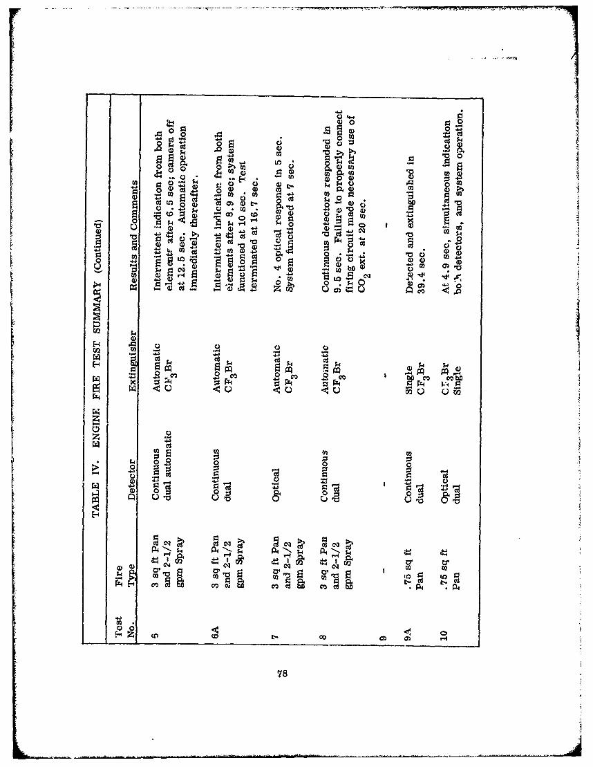
cd 0 m
CO . ~0 C)
o- 0J. .-
0 .o m 0~ W )5W4 C14 14L-PQ
00
$4 ) cn 0)W'g (a 00 0 0
C) -d a )0
4) m. .. g,0-4G
T-4 4 .4.4 El 04
(D ua~I1
CO LO
k~ g.4pq
CCID
0060
0) 0
L78

OD0 w00 cq0
00
S0-
~ ~0 0 0oI' c34-A* >1 2
0E-4
3 02200
Q 79
00 0
0E- 4
~.402 - -
pqcq
79

4) 0.
'40 LOC'01) 02.)
4.)0
14 00) 0 d)4) CU .0 IR M)
'40 020 a~ C0
V2 m' ý4aC .0
_4 '0 0 0) 'D -4 e
6,01 *P, 4mO r4~ r-*4
0- Wv ~ U 0~'
~~~~~p I i ' IiII i.~r g
PF4 PZ F~ r4 ;F 4 Pr4 ;
1--4
Z 00

Test 12 was conducted with one element open in order to establish that the self-interrogating control would function under this condition. When control receivedan alarm from only one elemant, it automatically tested the second eiement;when this element was shown to be defective (open), the fire signal was given and
the system functioned.
In test 13, the optical. system employing a self-interrogating control was testedwith one detector head disconnected, and Jt too functioned satisfactorily.
In the following tests, 14 through 18, main and reserve extinguishing systemswere used, and the ventilation air shutoff system was deactivated in order toallow rapid dissipation of the agent from the first shot and permit reignition in areasonable period.
Test 14 employed dual optical detectors and a main and reserve extinguishingsystem. This test revealed that the optical detector circuits were not function-ing properly.
Test 15 employed dual continuous elements in an interrogating circuit with dualextinguishers in a main and reserve configuration as depicted in Figure 6. In
this test, initial system operation took place at 21 seconds with the reserve sys-tem discharging 122.5 seconds later. Because of some intermittent responsesin the element circuits, the wiring to the test compartment was changed to sepa-rate the element leads from the cable bundle.
In test 15A, ignition did not occur due to carbon buildup on the ignitor insulators,causing arcing to take place away from the fuel spray. After cleaning the insula-tors, tes t 15B was run. In an effort to determine if the rerouting of the wiringwould also resolve the problem (intermittent operation of the optical units),optical detectors were used in 15B. Initial systeai operation took place in 21seconds and reserve 65 seconds later, indicating this was not the correctionnecessary for the optical system. The problem was corrected by obtaining themanufacturer's control units to replace the simplified routing circuits.
Test 16A employed dual continuous detectors with an interrogating control circuitwith main and reserve extinguishers. Within 11 seconds of ignition circuit activa-tion, the first element responded with a signal; at 12.5 seuonds the other elementlight was activated along with the first fire bottle. At 20 seconds all systemswere cleared, and when reignition took place, the elements responded in thesame order, firing the reserve bottle at 98.5 seconds after original ignition.
Test 17 employed dual optical detectors in an interrogating circuit with the ex-tinguisher system set up as a mai._ and reserve system as illustrated in Figure 9.The first detector responded within 0.2 second of the throwing of the ignition
81

switch. The second detector indicated at 0.4 second, simultaneously operatingthe initial extinguisher bottle. Both detectors had cleared by 0.8 second. Itwas approximately 2.5 minutes before reignition was indicated by the fire warn-ing light (there was no visual evidence of flame). Response was almost instan-taneous, and the fire was extinguished by the reserve extinguisher.I
The detailed sequence of events for tests 16A and 17 is shown in Table V.
In the case of the optical detector, an automatic operation of the sequence ofdetection and extinguishing was so rapid that there was no visible evidence offire. Test 18 was run to confirm the presence of fire. A 3-inch hole was cut inthe cowl and the camera focused on the electrodes. In addition to the arcing atthe tips of the electre-ie, sparks were jumping on the holder due to carbon build-up. When fuel spray started, ignition and the resulting fire were eas-iy dis-cernible and the fire was completely extinguished in 0.5 second. The test used "4
a dual optical detector in the interrogating circuit with automatic operation ofa single extinguisher.
OIL COOLER COMPARTMENT
A 1600 cfm fan was installed in this compartment to duplicate the oil cooler fan.The protection system shown in Figure 10 consisted of two optical detectorswhich upon sighting a fire would automatically fire an extinguisher bottle andremove power from the fan and stop the fuel flow, simulating operation of a by-pass valve. The extinguisher was one of the 86 cu in. units used in the engine.
The test setup is shown in Figures 25 and 26. The 3-square-foot pan wasplaced in the compartment with a 5-gpm fuel nozzle.
MIL-L-23699 oil was used as the fuel, and preliminary tests indicated that itwould not ignite even in the spray pattern issuing from the nozzle. A highlyflammable JP-4 soaked paper towel was introduced into the pan of MIL-L-23699lubricating oil adjacent to the spark gap and directly in the oil spray, and ahighly satisfactory fire resulted.
The test was ini-iatý,d with th- fan started and allowed to come up to speed. Theignition circuit was activated, and fire started. The system sensed the fire andthe fuel spray was cut off automatically as was the fan power; simultaneously,the extinguisher was fired and the fire was extinguished.
82

TABLE V. TIMED SEQUENCE OF EVENTS (ENGINE COMPARTMENT)
Test TimeNo. (sec) Action
16A 8 Ignition and fuel spray initiated
Alarm from one element A
20.5 Alarm from second element BClose vent signal(No closing,vent system intentionally disabled)First fire extinguished
25.5 B element cleared
28.5 A element cleared
105 A element alarm
106.5 B element alarmReserve fire extinguisher fired
112 B element cleared
113.5 A element cleared
17 12.2 Fuel on
12.3 Ignition
12.5 Alarm from A detector
12.7 Alarm from B detectorClose vent signal(No closing vent intentionally disabled)First extinguisher fired
13 A detector cleared
13.1 B detector cleared170+ A detector alarm
170+ 1) B detector alarm
Reserve extinguisher fired
170+ (+.3) A and B detectors cleared
83

VTV-
jwI
84

I-' -
I _ _ _
reI
85I

ELECTRONIC COMPARTMENT
Test 20 was that of the electronic compartment. The simulated compartment isshown in Figure 27. A smoke detector was installed on the upper surface. Theinitial smoke generator was a small soldering iron with rubber insulating mate-rial placed on the tip. The amount of smoke generated from this was exceed-ingly light, so a hot plate was installed In the bottom of the compartment andadequate smoke was generated by placing paper towels saturated with MIL-L-23699 turbine oil directly on the hot plate surface. In this system, the interfaceunit (upon receipt of an alarm from the smoke detector) lighted an indicatorlight and removed power from the section - no extinguisher was used since thetype of fire encountered would be self-extinguishing once power was removed.This system is shown In Figure 14.
Two indicator lights were used - one normally off came on when the smoke Adetector alarmed (smoke detector light), and the other normally on, indicatingpower on, went off upon alarm, indicating "power off"t.
This test represented a functional test of this setup. The smoke detector sensedthe smoke, and all systems operated satisfactorily.
A
86

__ ced
to4

CONCLUSIONS
It is completely practical to combine existing fire detection and extinguishingequipment with state-of-the-art interface units into an effective automatic firesuppression system for Army rotary-wing aircraft.
The interrogating system. which employs sensors in pairs and responds only ifboth sensors Indicate fire or if one sensor Indicates fire and the other indicatesa fault can provide a margin in reliability which makes a fully automatic systempractical.
In the event of a fire In the engine space, continued operation for periods up toseveral minutes may be gained by the use of an automatic suppression system.This period may be doubled by the addition of a reserve system. More ex-tended operation can be gained by providing a means to control the flow ofventilation air Into the compartment.
The oil cooler compartment presents much less of a hazard than the enginespace. If fuel drainage in the engine space above it were adequate to preventleaking fuel from getting into this compartment, this space might not be con-sidered as an area needing protection since the high (475°F) flash point of theoil makes ignition highly unlikely. The use of dual outlet containers for theengine space extinguishing system, coupled with the addition of a detector in theoil cooler compartment would, however, allow coverage in this space with mini-mum cost and weight impact.
The test of the smoke detector in the electronics bay indicated that considerable
smoke was necessary to activate the system. However, the hazard is one inwhich voluminous generation Of 3moke would precede any other indication of firesuch as heat or visual evidence of flame. We therefore confirm the suitabilityof this means !or this hazard. We do not, however, feel that the performance
record would warrant its installation.
It is believed that the problem of battery fires can be resolved by steps outlinedIn a recent FAA Airworthiness Directive. This directive requires very closeinspection uniil all polystyrene cased cells have been replaced or suitable tem-perature sensing and disconnect or charging rate control procedures have beeninstitated.
Those flres in crew-accessible spaces may be detected by the crew and propersteps taken to remove power and if necessary use portable extinguishing equip-men't to extinguish the fire.
88

RECOMMENDATIONS
It is recommended that at the very minimum, an Automatic Fire Detection andSuppression System be provided in the engine space of the UH-1 aircraft. Theoptimum system from a suppression standpoint would be one in which airflowcould be minimized. However, from a practical point of view, a main andreserve system in the engine space might provide enough time for the pilot toland safely.
It is recommended that further tests be run with an actual engine compartment.
A dual system with a self-interrogating control would provide the high order ofreliability against both false and no-alarm conditions. A continuous thermaldetector, or a visual detector with a more positive integrity test, could be usedas the sensor.
It is recommended that the possible drainage of fuel from the engine to the oilcooler compartment be corrected or that an automatic detection and suppressionsystem be provided in this space.
It is not recommended that a system be provided for the electrical compartment.
We suggest careful review of the results obtained with self-sealing crash resist-ant fuel cells to determine if the fuel cells and space surrounding them need beprotected.
It is recommended that the problem of battery fires be corrected by directpreventive means rather than an automatic fire detection and suppression system.
89

LITERATURE CITED
1. Pedrlani, Charles M., A STUDY OF THE FUEL/AIR VAPORCHARACTERISTICS IN THE ULLAGE OF AIRCRAFT FUELTANKS, U. S. Army Aviation Materiel Lat.- atoies, . TN3,Fort Eustis, Virginia, June 1970, AD 873252.
2. Nestor, L. J., INVESTIGATION OF TURBINE FUELFLAMM~hABILITY WITHIN AIRCRAFT FUEL TANKS,Naval Air Propulsion Test Center, Philadelphia, Pa.,
rS-67-7, July 1967, AD 669001.
I I
3. _lueg, Eugene P., IN FLIGHT CONTROL OF POWERPLANTIRES WITH LIQUID NITHOGEN, Second Conference on Fuel
System Fire Safety Report of Conference, Federal AviationAdministration, 6 and 7 May 1970, page 122.
4. Rolle, Stephen H., REPORT OF FAA INDUSTRY ADVISORYCOMMITTEE ON FUEL SYSTEM FIRE SAFETY, Second
Cofrneo ulSystem Fire Safety Report of Conference, eea Aito
Federal Aviation Administiation, 6 and 7 May 1970, page 10.
5. Business Pilot's Safety' Bu! 'n, 71-209, Flight SafetyFoundation, Inc., 1800 N. Kent St., Arlington, Va.
90

SELECTED BIBLIOGRAPHY
.tti INVESTIGATION OF IN-FLIGHT FIRE PROTECTION WITH A TURBOFANPOWERPLANT INSTALLATION, FAA National Aviation Failities ExperimentalCent3r, Report NA-69-26, April 19469.
Custard, G. H., et. al., AIRCRAFT FUEL CELL EXPLOSION SUPPRESSIONSYSTEMS AND THEIR APPLICABILITY TO ARMY AIRCRAFT, Falcon
Resept.-ch aAf Development Company, Denver, Colorado; U. S. Army AviationMat.,i.--1 Laboratories, Fort Eustis, Virginia, TR 67-39, July 1967, AD 824028.
Federal Aviation Agency Technical Standard .jrder Clb Cargo and BaggageCompartment Smoke Detection Instruments, March 24, 1967.
Federal Aviation Agency Technical Slandard Order Clld, Subject Fire Detectors.August 30, 1961.
Federal Aviation Agency Technical Standard Order C-79 Fire DetectorsUr.adiation Sensing ype), November 12, 1963.
Y ~*II•XTINGLISTMENT IN AIRCRAFT VOI) SPACES, Fenwal, Inc.,B BRL), August 1969, AD 504144.
Hansberry, H. L., AIRORAFT FIRE PROTECTION DEVELOPMENTS BY THEFEDERAL AVIATION ADIMINISTRATION (1940-1970), ASME Paper 70-GT-109,May 1970, 24-28.
Kuchta, J.M., et. al., EVALUATION )F FLAME ARRESTOR MATERIALSFOR AIRCRAFT FUEL SYSTEMS, Bui-au of Mines; Air Force Aero PropulsionLaboratory, TR-67-148, February 1968, AD 828014.
Kuchta, J. M., et. al., FUEL TANK EXPLOSION SUPPRLSSION, Bureau ofMines; Air Force Aero Propulsion Laboratory, TR-69-11, March 1969,AD 849701.
Kuchta, J.M., et. al., FLAME ARRESTOR MATERIALS FOR FUEL TANKEXPLOSION PROTECTION, Bureau of Mines; Air For Aero PropulsionLaboratories, TR-70-40, July 1970.
Metcalf, J.W., et. al., PROTECTION OF AIRCRAFT FLUID SYSTEMS,LTV Aerospace Corporation; Air Force Materials Laboratory, TR-68-125,April 1968.
91

SELECTED BIBLIOGRAPHY (Cont)
Military Specification MIL-C-22284A (Wjp), Container, Aircraft FireExtinguishing System, Bromotrifluoromethane, CF3Br, 7 September 1965.
Military Specification MIL-D-27729A (USAF), Detecting systems, Flame andSmoke, Aircraft and Aerospace Vehicle, General Performance, Installationand Test of, 25 June 1963.
Military Speciication MIL-D-7599 (WAF)& Detector, Overheat, Adjustable,149°C to 3990C Range, Type E-2, 10 November 1952.
Military Specification IML-E-22285 M.EP), Extinguishing System, Fire,Aircraft, High-Rate-Die.harge Type, Installation and Test of, 27 April 1960(Amend. 1).
Military Ie(.iication MIL-E-52031, Extinguisher, Fire, Vaporizing Liquid,CCF 3 Br, 2-3/4 -Itnd with Bracket, 2 January 1968.
Military Specification MIL-F-23447 (WEP), Fire Warning Systems, Aircraft,Radiation Sensing Type, Test and Installation of, 14 September 1962.
Military Specification MIL-F-7872 (ASG) Fire and Overheat Warning Systems,Continuous Aircraft: Test and Installation of, 18 November 1966.
Nestor, L.J., INVESTIGATION OF TURBINE FUEL FLAMMABILITYWITHIN AIRCRAFT FUEL TANKS, Naval Air Propulsion Test Center,Philadelphia, Pa., DS 67-.7, July 1967, AD t669001.
N. F. P.A. Quarterly, October 1957.
Pedriani, Charles M., A STUDY OF THE FUEL/AIR VAPOR CHARACTER-ISTICS IN THE ULLAGE OF AIRCRAFT FUEL TANKS, U. S. Army AviationMateriel Laboratories, TN3, Fort Eustis, Virginia, June 1970, AD 873252.
Reed, Thomas D., USAF EXPERIENCE WITH POLYURETHANE FOAMINERTING MATERIAL, ASD, Directorate of Propulsion and Power,ASNJ1-70-2, May 1970.
SECOND CONFERENCE ON FUEL SYSTEM FiRE SAFETY, Report ofConference, 6 and 7 May 1970.
Technical Development Report No. 260, CAA Technical Development andEvaluation Center, Indianapolis, February 1956.
92

SELECTED BIBLIOGRAPHY (Cont)
Thibodeau, J.E., FUEL FIRE PROTECTION DEVICE FOR SMALL HEI
PROJECTILE THREAT, Goodyear Tire and Rubber Company, AviationProducts Division; August 1969 (19-607), AD 859970.
93