usariem technical report t-03/16 a comparison of the
TRANSCRIPT

USARIEM TECHNICAL REPORT T-03/16
A COMPARISON OF THE SCORPION LOAD CARRIAGE SYSTEM (SLCS) TO THE MODULAR LIGHTWEIGHT LOAD CARRYING EQUIPMENT (MOLLE)
Michael E. LaFiandra Suzanne Lynch Peter Frykman Everett Harman
SPC Hipolito Ramos SPC Heath Isome
Robert Mello
Military Performance Division
July 2003
U.S. Army Research Institute of Environmental Medicine Natick, MA 01760-5007


Table of Contents
Section Page
List of Figures.................................................................................................................. v
List of Tables...................................................................................................................vi
Acknowledgments ......................................................................................................... viii
Acknowledgments ......................................................................................................... viii
Executive Summary ........................................................................................................ 1
Introduction ..................................................................................................................... 2
Methods .......................................................................................................................... 4 Research Volunteers ............................................................................................ 4
Sample Size Estimation ............................................................................. 4 Research Volunteers ................................................................................. 4 Research Volunteer Briefing ...................................................................... 4
Site of Testing and Training.................................................................................. 4 Study Design ........................................................................................................ 5 Data Collection ..................................................................................................... 6
Biomechanics Data Collection ................................................................... 7 Physical Performance Data Collection....................................................... 7 IMT Data Collection Session:..................................................................... 9
Data Analysis........................................................................................................ 9 Statistics .................................................................................................... 9 Force Plate Treadmill............................................................................... 10 Gait Kinematics........................................................................................ 10 Oxygen Uptake ........................................................................................ 10 Heart Rate ............................................................................................... 11
Results .......................................................................................................................... 11 Biomechanics ..................................................................................................... 11
Joint Kinematics....................................................................................... 11 Lower Limb Joint Reaction Forces........................................................... 27 Lower Limb Joint Torques........................................................................ 33 Ground Reaction Force Variables............................................................ 34 Impulses .................................................................................................. 36 Backpack Movement ............................................................................... 37
Metabolic cost..................................................................................................... 49

Obstacle Course................................................................................................. 54 Individual Movement Techniques ....................................................................... 62
Responses to Post IMT Questionnaire .................................................... 67 Responses to Exit Survey........................................................................ 72
Discussion..................................................................................................................... 75
Conclusions................................................................................................................... 78
References.................................................................................................................... 80
Appendix A.................................................................................................................... 82

List of Figures Figure # Page 1 Knee Angle Defined..................................................................................... 11 2 Maximum Knee Flexion / Extension Angle................................................... 12 3 Minimum Knee Flexion/Extension Angle...................................................... 13 4 Time of Minimum Knee Flexion / Extension Angle....................................... 14 5 Hip Angle Defined........................................................................................ 15 6 Maximum Hip Flexion / Extension Angle...................................................... 16 7 Minimum Hip Flexion / Extension Angle....................................................... 17 8 Hip Flexion / Extension Range of Motion ..................................................... 18 9 Time of Minimum Hip Flexion / Extension Angle.......................................... 19 10 Trunk Angle Defined .................................................................................... 20 11 Maximum Trunk Angle ................................................................................. 21 12 Minimum Trunk Angle .................................................................................. 22 13 Trunk Range of Motion ................................................................................ 23 14 Time of Maximum Trunk Angle .................................................................... 24 15 Shoulder Angle Defined............................................................................... 25 16 Shoulder Flexion/Extension Range of Motion .............................................. 26 17 Time of Maximum Ankle Joint Reaction Force............................................. 28 18 Average Ankle Joint Reaction Force............................................................ 28 19 Average Knee Joint Reaction Force ............................................................ 30 20 Time of Maximum Knee Joint Reaction Force ............................................. 30 21 Time of Maximum Hip Joint Reaction Force ................................................ 31 22 Average Hip Joint Reaction Force ............................................................... 32 23 Minimum Ankle Joint Torque ....................................................................... 34 24 Time of Minimum Midstance Vertical Ground Reaction Force ..................... 35 25 Maximum Push Off Vertical Ground Reaction Force ................................... 35 26 Total Vertical Impulse .................................................................................. 36 27 Maximum Backpack Center of Mass Vertical Position................................. 38 28 Minimum Backpack Center of Mass Vertical Position.................................. 38 29 Time of Maximum Backpack Center of Mass Vertical Velocity .................... 40 30 Time of minimum backpack center of mass vertical velocity........................ 40 31 Maximum Backpack Center of Mass Anterior Velocity................................. 42 32 Maximum Backpack Center of Mass Posterior Velocity............................... 42 33 Time of Maximum Backpack Center of Mass Vertical Acceleration ............. 44 34 Time of Minimum Backpack Center of Mass Vertical Acceleration .............. 44 35 Maximum Backpack Center of Mass Anterior Acceleration ......................... 46 36 Maximum Backpack Center of Mass Posterior Acceleration........................ 47 37 Time of Maximum Backpack Center of Mass Anterior Acceleration ............ 47 38 Time of Maximum Backpack Center of Mass Posterior Acceleration........... 48 39 Oxygen Consumption (VO2) ........................................................................ 50 40 Carbon Dioxide Production (VCO2).............................................................. 50 41 Oxygen Consumption per Unit Body Mass (VO2/BM) .................................. 51 42 Oxygen Consumption Per Unit Total Mass (VO2/TM) .................................. 52 43 Oxygen Consumption as a Percent of Baseline Oxygen Consumption ....... 53 44 Stand to Prone............................................................................................. 63

45 Prone to Stand............................................................................................. 63 46 Time to Doff the Backpack........................................................................... 64 47 Time to Complete the Combat Roll .............................................................. 65 48 Time to Donn the Backpack......................................................................... 66 49 Time to Complete the Low Crawl - Fighting Load ........................................ 55 50 Time to Traverse the Large Window - Fighting Load ................................... 56 51 Time to Traverse the Small Window - Fighting Load ................................... 56 52 Time to Traverse Entire Obstacle Course - Fighting Load ........................... 57 53 Time to Complete Low Crawl - Approach Load ........................................... 59 54 Time to Traverse Medium Window - Approach Load................................... 59 55 Time to Climb Stairs - Approach Load ......................................................... 60 56 Time to Traverse Large Window - Approach Load ...................................... 61
List of Tables Table # Page 1 Equipment and weights for typical Fighting load............................................ 5 2 Approximate total load to be carried in each configuration ............................ 6 3 P-Values for Knee Kinematics ..................................................................... 12 4 Maximum Knee Flexion/Extension Angle..................................................... 13 5 Minimum Knee Flexion/Extension Angle...................................................... 14 6 Time of Minimum Knee Flexion/Extension Angle......................................... 15 7 P-Values for Hip Flexion/Extension Kinematics ........................................... 16 8 Maximum Hip Flexion/Extension Angle........................................................ 17 9 Minimum Hip Flexion/Extension Angle......................................................... 18 10 Hip Flexion/Extension Range of Motion ....................................................... 19 11 Time of Minimum Hip Flexion/Extension Angle............................................ 20 12 P-Values for Trunk Kinematics .................................................................... 21 13 Maximum Trunk Angle ................................................................................. 22 14 Minimum Trunk Angle .................................................................................. 23 15 Trunk Angle Range of Motion ...................................................................... 24 16 Time of Maximum Trunk Angle .................................................................... 25 17 P-Values for Shoulder Kinematics ............................................................... 26 18 Shoulder Flexion/Extension Range of Motion .............................................. 27 19 P-Values for Ankle Kinetics.......................................................................... 27 20 Time of Maximum Ankle Joint Reaction Force............................................. 28 21 Average Ankle Joint Reaction Force............................................................ 29 22 P-Values for Knee Kinetics .......................................................................... 29 23 Average Knee Joint Reaction Force ............................................................ 30 24 Time of Maximum Knee Joint Reaction Force ............................................. 31 25 P-Values for Hip Kinetics ............................................................................. 31 26 Time of Maximum Hip Joint Reaction Force ................................................ 32 27 Average Hip Joint Reaction Force ............................................................... 33 28 P-Values for Lower Limb Torques ............................................................... 33 29 Minimum Ankle Joint Torque ....................................................................... 34 30 P-Values for Ground Reaction Force Variables ........................................... 34 31 Time of Minimum Midstance Vertical Ground Reaction Force ..................... 35

32 Maximum Push Off Vertical Ground Reaction Force ................................... 36 33 P-Values for Impulse Variables.................................................................... 36 34 Total Vertical Impulse .................................................................................. 37 35 P-Values for Backpack Position Variables ................................................... 37 36 Maximum Backpack Center of Mass Vertical Position................................. 38 37 Minimum Backpack Center Of Mass Vertical Position ................................. 39 38 P-Values for Backpack Vertical Velocity Variables ...................................... 39 39 Time of Maximum Backpack Center of Mass Vertical Velocity .................... 40 40 Time of Minimum Backpack Center of Mass Vertical Velocity ..................... 41 41 P-Values for Backpack Horizontal Velocity Variables .................................. 41 42 Maximum Backpack Center of Mass Anterior Velocity................................. 42 43 Maximum Backpack Center of Mass Posterior Velocity............................... 43 44 P-Values for Backpack Vertical Acceleration Variables ............................... 43 45 Time of Maximum Backpack Center of Mass Vertical Acceleration ............. 44 46 Time of Minimum Backpack Center of Mass Vertical Acceleration .............. 45 47 P-Values for Backpack Horizontal Acceleration Variables ........................... 45 48 Maximum Backpack Center of Mass Anterior Acceleration ......................... 46 49 Maximum Backpack Center of Mass Posterior Acceleration........................ 47 50 Time of Maximum Backpack Center of Mass Anterior Acceleration ............ 48 51 Time of Maximum Backpack Center of Mass Posterior Acceleration........... 49 52 P-Values for Metabolic Cost Data................................................................ 49 53 Oxygen Consumption (VO2) ........................................................................ 50 54 Carbon Dioxide Production (VCO2).............................................................. 51 55 Oxygen Consumption per Unit Body Mass (VO2/BM) .................................. 52 56 Oxygen Consumption Per Unit Total Mass (VO2/TM) .................................. 53 57 Oxygen Consumption as a Percent of Baseline Oxygen Consumption ....... 54 58 P-Values for Individual Movement Techniques............................................ 62 59 Stand to Prone............................................................................................. 63 60 Prone to Stand............................................................................................. 64 61 Time to Doff the Backpack........................................................................... 65 62 Time to Complete the Combat Roll .............................................................. 66 63 Time to Donn the Backpack......................................................................... 67 64 P-Values for Obstacle Course - Fighting Load............................................. 54 65 Time to Complete the Low Crawl - Fighting Load ........................................ 55 66 Time to Traverse the Large Window - Fighting Load ................................... 56 67 Time to Traverse the Small Window - Fighting Load ................................... 57 68 Time to Traverse Entire Obstacle Course - Fighting Load ........................... 58 69 P-Values for Obstacle Course - Approach Load .......................................... 58 70 Time to Complete Low Crawl - Approach Load ........................................... 59 71 Time to Traverse Medium Window - Approach Load................................... 60 72 Time to Climb Stairs - Approach Load ......................................................... 61 73 Time to Traverse Large Window – Approach Load...................................... 62

ACKNOWLEDGMENTS
The authors would like to thank Cara Leone for her assistance in data collection. Additionally, the authors would like to thank Will Tagye for his assistance in training the subjects on MOLLE and his assistance during data collection.

EXECUTIVE SUMMARY
The U.S. Army is developing Scorpion as an integrated fighting system for the dismounted soldier of the future. Scorpion is the next generation of Land Warrior, and incorporates technology that likely will be transitioned to the Objective Force Warrior. The Scorpion system incorporates integrated ballistic and armor protection, an advanced load carriage design and modern digital technology to increase the survivability and lethality of the soldier.
The unique load carriage design of Scorpion was deemed likely to result in differences in the metabolic cost, joint reaction forces, load distribution, and maximal performance capabilities of soldiers compared to the Modular Lightweight Load Carrying Equipment (MOLLE) system, which is planned to be fielded for the Army, and is currently fielded and used by the Marines. Thus, the purpose of this study was to evaluate the effects of the Scorpion Load Carriage System (SLCS) on biomechanics, oxygen consumption and performance on militarily relevant tasks. An additional goal was to compare the SLCS to the MOLLE system. Eleven subjects completed testing that took place over a 3-week period. Biomechanics testing included treadmill walking at 3 mph (1.34 m·s-1) with the SLCS and MOLLE in 3 different configurations that include Fighting, Approach, and Sustain (ranging from 60 to 120 pounds; 27.2 to 54.4 kg) loads. During treadmill walking, high-speed video data provided information on the motion of the body segments; force platform data provided information on the forces exerted on the body; and oxygen consumption data allowed inference of metabolic cost. Performance measures included timing of: obstacle course traversal, 2-mile road march, and individual movement techniques (IMTs). These tests were performed while carrying the Fighting and Approach loads. Descriptive statistics were performed, and analysis of variance (ANOVA) was used to determine whether significant differences existed in the dependent measures across the various configurations.
Both the MOLLE and the SLCS performed well during these tests. The most noteworthy difference between the load carriage systems was a lower metabolic efficiency while carrying Scorpion than MOLLE. It may be the case that the corset design of the SLCS constrained chest wall expansion and inhibited breathing. However more research is needed before a definitive conclusion can be drawn. Additionally, there was some evidence of a greater performance decrement on the obstacle course after a 2-mile march while carrying Scorpion; this may be a consequence of the decreased metabolic efficiency observed with this system. However, only one obstacle displayed such a performance decrement. Minor performance differences in IMTs and on the obstacle course were also noted between MOLLE and Scorpion. For the Fighting load, subjects traversed both the low crawl and small window faster with Scorpion than with MOLLE. Additionally, the total time to complete the obstacle course with the Fighting load was faster with Scorpion than with MOLLE. Similarly, with the Approach load, Scorpion times for the low crawl, medium window, and upstairs run were shorter than MOLLE times. There were biomechanical differences between the load carriage systems that did not indicate superiority of one system over the other.
1

INTRODUCTION
Journal articles cited in this report were located via several MedLine searches, the last of which was conducted in September 2002. Technical reports and military laboratory work cited in this report were located via a Defense Technical Information Center (DTIC) search for related technical reports (search AML50D) and work units (search SML54E) performed in September 2002 using various combinations of the keywords “backpack” and “load carriage”.
The effects of backpack mass on biomechanics and metabolic cost are well documented (7, 8, 10, 11, 15-20). Previous research has also shown differences in GRF, lower limb joint kinematics, and metabolic cost between backpack systems, even when the backpacks’ masses are comparable (5). These differences have been attributed to differences in backpack design, such as center of mass (COM) location. For instance, changes in backpack COM position alter trunk flexion (increase forward lean), thereby influencing the motion of the trunk and lower leg segments and in turn, affect GRF. Research has also shown maintaining a COM location that is high and close to the body results in a decrease in metabolic cost, and lower limb joint reaction force (15). The unique load carriage design of Scorpion was deemed likely to result in differences in the COM location and the distribution of the load compared to MOLLE, and consequently differences in kinetics and kinematics. Quantifying the differences in kinetics and kinematics between SLCS and MOLLE can provide insight into which backpack has the least potential for injury associated with increases in GRF.
GRF is a measure of the force exerted by the foot on the ground in three standard orthogonal planes during gait. Knowledge of GRF enables a researcher to calculate joint reaction forces and torques and thus is important to biomechanical analyses. A force plate treadmill system was designed by the biomechanics team at USARIEM, which specified the requirements of the force plate system and treadmill to the engineers at AMTI (Watertown, MA 02744). AMTI built the integrated force plate treadmill system (FPTM) that is capable of measuring GRF in three planes during walking. Data were sent from the force transducers in the treadmill to a dedicated computer, which also receives information about the treadmill speed and incline. Because subjects walk at a constant speed for several minutes at a time on a treadmill, they reach steady state, a condition necessary to accurately measure oxygen consumption. The FPTM allows large volumes of biomechanics data to be collected quickly, resulting in greater efficiency of data collection, and allows for oxygen consumption and joint reaction force data to be collected simultaneously. In addition, the use of the treadmill provides a mechanism by which all subjects can be exposed to the exact same protocol.
The forces exerted between the foot and the ground are only one set of variables that may be influenced by the design of the backpack. Another variable may be the motion of the backpack in relation to the body (7). Excessive backpack motion may affect the magnitude, timing and variability of forces exchanged between the backpack and the carrier, which may require an increase in muscle force to control the motion of
2

the backpack (1, 12). The small muscle groups of the back act in supporting and stabilizing roles during load carriage; if the motion of the backpack is unstable these muscles may be placed under greater strain (14). One consequence of increases in muscle force may be an increase in muscle soreness. In addition, excessive motion of the backpack may serve to perturb the motion of the trunk, thereby resulting in a decrease in stability during walking, and an increase in the potential for falls (12).
Changes in backpack design are additionally associated with differences in performance on militarily relevant tasks, such as time to complete an obstacle course. Harman et al., (5, 6) showed MOLLE was associated with an increase in time to complete an obstacle course (compared to a competing backpack design); this was likely due to MOLLE having a larger front-back dimension than other designs. The larger front-back dimension resulted in interference between MOLLE and some of the obstacles. Interference between the load carriage system, the helmet, and the body armor has also been a problem. An after action report from Afghanistan (3) illustrates an incompatibility between the ceramic plates in the ballistic vest, the Kevlar helmet and the All Purpose Load Carrying Equipment (ALICE) rucksack. Simply stated, the three rigid materials (ceramic in the body armor, the metal ALICE frame, and the Kevlar helmet) prevented head movement in soldiers when all three were worn at the same time and the soldier was in the prone position. Performance testing prior to the procurement of these three systems would have alerted designers to this incompatibility.
Common performance measures used in the evaluation/comparison of backpack systems include a timed 2-mile road march, obstacle course traversal, and time to complete IMTs (5, 6). These tasks were chosen because they are designed to simulate battlefield activities that may be affected by load carriage. The obstacle course traversal, 2-mile road march and IMTs are timed tasks; the longer it takes the volunteer to complete the task, the worse the score. Previous backpack studies have compared the effects of backpack design on obstacle course and 2-mile road march times separately. This allowed the researchers to report the effect of each backpack on the time to complete each of the tasks individually. For instance, Harman et al. (5) has shown differences in timed 2-mile road march performance between backpack designs (weights similar to what we will be testing) in the range of 14-19 seconds. Aside from information on performance, the obstacle course may additionally provide information on incompatibilities between the components of the SLCS.
The purpose of this research was to evaluate the effects of the SLCS on biomechanics, oxygen consumption during treadmill walking and on soldier performance of tasks such obstacle course traversal, IMTs and a timed 2-mile road march, and additionally to compare the SLCS to MOLLE on these measures.
3

METHODS
RESEARCH VOLUNTEERS
Sample Size Estimation
For repeated measures sample size estimation, the method of Cohen (4) was used. The FPTM incorporates high-grade commercial force transducers from a company whose systems have shown test-retest reliabilities in the range of 0.99. The smallest difference between means of forces we deemed of practical significance was 5%. Because data were not yet available for the FPTM system, previously collected data from a similar force platform were used to estimate variability in force measurements. Data from our study on the MOLLE load carriage system showed standard deviations of vertical ground reaction force during walking of no more than 15% of the mean. Therefore, we looked for an effect size of .33 standard deviation units. Adjusting the effect size for repeated measures according to Cohen’s method, using a conservative 0.95 reliability for the new FPTM system, our adjusted effect size was 1.48. Entering the appropriate table under a power of 0.80, the number of subjects needed was 9. In order to account for possible volunteer withdrawals, we sought 12 volunteers.
Research Volunteers
Eleven healthy male subjects participated in this study. Subjects were selected from the U.S. Army Natick Soldier Center, Natick, Massachusetts pool of military volunteers. Only subjects over 120 pounds, between the ages of 18 and 35, and that were physically fit (as measured by passing the Army Physical Fitness test within the previous six months) were accepted as volunteers. Subjects had no history of back problems or known current injuries or defects to bones or joints, including herniated intervertebral discs or previous orthopedic injuries that limited the range of motion about the shoulder, hip, knee or ankle joint. Prior to participation, subjects gave informed consent and signed a Volunteer Agreement Affidavit (DA Form1487).
The investigators have adhered to the policies for protection of human subjects as prescribed in Army Regulation 70-25, and the research was conducted in adherence with the provisions of 45 CFR Part 46.
Research Volunteer Briefing
The principal investigator conducted informed consent briefings to explain the study protocol, associated risks, safeguards to be employed to minimize risks, direct benefits and to answer questions related to participation in the study. Informed consent was obtained from those who chose to volunteer.
SITE OF TESTING AND TRAINING
Data were collected in the Center for Military Biomechanics, located in Building 45 of the U.S. Army Natick Soldier Center, Natick, MA.
4

STUDY DESIGN
Prior to data collection, anthropometric measures of hip and shoulder width were taken. Body mass and height were measured using a balance scale.
There were three loads that replicated Fighting, Approach and Sustainment loads. Biomechanics testing included both load carriage systems, and three load configurations (6 conditions total). Performance testing included both load carriage systems but only two load configurations (Fighting and Approach; 4 conditions total).
The MOLLE Fighting load included Interceptor Body Armor, the Fighting Pack, BDUs, gloves, the Modular Integrated Communications Helmet (MICH), 2 quarts of water and combat boots. The weight of the MICH helmet was less than 5 pounds (2.27 kg). The weight of the unloaded MOLLE Fighting system including all of these components was 41.2 pounds (18.6 kg); this weight did not include the weapon or ammunition. The MOLLE Approach pack added 11.1 pounds (5.0 kg; total Approach weight without weapon or ammunition is 52.3 pounds, 23.72 kg); the Sustainment pouches and side pockets increased the weight another 3 pounds (1.36 kg; total Sustainment weight without weapon or ammunition is 55.3 pounds, 25.1 kg).
The SLCS Fighting Load included integrated body armor, a load carriage chassis, side assault packs, ballistic utility belt, combat uniform, combat chaps, combat boots, gloves, knee and elbow pads, two 1.5 liter canteens, and the Scorpion helmet. The weight of the Scorpion helmet (as it was tested in this experiment) was less than 5 pounds (2.27 kg). The weight of the unloaded SLCS Fighting system including all of these components was 37.6 pounds (17.1 kg); this weight did not include the weapon or ammunition. The SLCS Approach pack adds 3 pounds (1.36 kg; total Approach weight without weapon or ammunition is 40.6 pounds, 18.42 kg); the Sustainment pouch added another 3 pounds (1.36 kg, total Sustainment weight without weapon or ammunition was 45.6 pounds, 20.70 kg).
According to FM 7-8, the typical Fighting load includes the equipment listed in Table 1:
Table 1: Equipment and weights for typical Fighting load Equipment Weight (lbs) Mass (kg)
Bayonet with Scabbard 1.3 0.58
Protective Mask with decontamination kit 3 1.36
Weapon, M16A2 with 30 rounds 5.56 Ball 8.8 3.99
Magazines each with 30 rounds of 5.56 mm (6) 5.4 2.44
Grenade, fragmentation (4) 4 1.81
Total 22.5 10.18
5

During testing, the volunteers carried simulated loads. These loads were made up of lead or iron weight surrounded by foam blocks. The foam blocks held the lead or iron weight in position and minimized the shifting of the load. The total load carried in each condition is summarized in Table 2.
Table 2: Approximate total load to be carried in each configuration Empty Pack* Simulated
Equipment Total "Skin-Out" ^
Condition (pounds) (kg) (pounds) (kg) (pounds) (kg) MOLLE Fighting 41.2 18.69 22.5 10.21 63.7 28.89SLCS Fighting 37.6 17.06 22.5 10.21 60.1 27.26
MOLLE Approach 52.3 23.72 42.5 19.28 94.8 43.00SLCS Approach 40.6 18.42 42.5 19.28 83.1 37.69
MOLLE Sustain 55.3 25.08 62.5 28.35 117.8 53.43SLCS Sustain 43.6 19.78 62.5 28.35 106.1 48.13
* Including helmet and ballistic protection ^ Skin out weight refers to everything the solider carried including boots, clothing, weapon ammunition, water, backpack and gear.
COM location affects the results of biomechanics, oxygen consumption and performance testing (6, 15). Because it is unknown how each pack will be packed in the field, the packs in this study were loaded based on the assumption of an even distribution of mass throughout the backpack. Therefore the COM of each backpack was as close to the geometric center of the pack as possible. Filling the pack with stiff foam blocks that surrounded iron or lead weights located in the center of the backpack allowed us to locate the COM of the backpack in the desired position.
DATA COLLECTION
Prior to data collection, subjects were briefed on our laboratory procedures and techniques, and given time to familiarize themselves with the treadmill and backpacks. A certified "New MOLLE Trainer" briefed the subjects on how to fit the MOLLE Fighting Load Carrier (FLC). A representative from Crye (the company that designed, developed and fabricate the SLCS and the Scorpion team was present during all of the testing that used the SLCS. The Crye representative assisted fitting the SLCS to the subjects before every test.
Because the SCLS was a prototype system, there were only 3 copies of the system available for testing. All 3 SLCS prototypes were the same size. All 11 subjects wore the same size SLCS, regardless of their height, weight, or other anthropometrics. Because MOLLE is a fielded item, it was available in any size necessary. Consequently, it was easier to size the Interceptor body armor and MOLLE to the subject than it was to size the SLCS to the subject, that is, the SLCS may have been too big for some subjects and too small for others. Biomechanics and IMT data
6

collection sessions were on the same day, and both biomechanics/IMTs data collection sessions took place before the physical performance data collection sessions.
Biomechanics data collection
The volunteers reported for biomechanics data collection sessions wearing shorts, a T-shirt, socks and combat boots. This was different from the other tests (in which volunteer was asked to report wearing Battle Dress Uniform or Under Armor Undergarment) because the reflective markers used for motion capture needed to be taped directly to the volunteer’s skin. Because the helmet interfered with the placement of the reflective markers on the head, the subjects did not wear a helmet during biomechanics testing. Reflective markers were placed on the subject's body at the fifth metatarsal head, ankle, knee, hip, shoulder, elbow, wrist, and side of the head, and three points on the backpack. During the biomechanics data collection sessions, the subjects walked on the treadmill at 3 mph (1.35 m·s-1) with both the SLCS and MOLLE under 3 load conditions (Fighting, Approach and Sustainment) for a total of 6 conditions. Additionally, in one of the biomechanics data collection sessions, subjects walked on the treadmill at 3 mph (1.35 ms-1) with no backpack. The order of backpack conditions was balanced across volunteers.
The subjects wore a Polar heart rate monitor chest strap and accompanying wristwatch for all backpack conditions. Oxygen consumption was monitored while walking. The volunteer wore a face mask connected by a flexible hose to a ParvoMedics (Salt Lake City, UT) TrueMax 2400 metabolic measurement system, to monitor oxygen uptake, and display and print oxygen uptake every 30 seconds. The volunteers were given approximately six minutes to reach steady state oxygen consumption, after which cameras captured the location of the reflective markers on the volunteer’s body. The force plates in the treadmill captured information about the GRF during these strides. The cameras and force plates collected data for 30 seconds, yielding approximately 25 strides of data. Oxygen consumption data were recorded for two minutes after the subject had reached steady state oxygen consumption.
Physical Performance Data Collection
The physical performance data collection session included the indoor obstacle course, and a timed 2-mile road march. When testing the MOLLE system, subjects completed all physical performance data collection wearing BDUs, combat boots, Interceptor body armor and MICH. When testing the SLCS, subjects completed all physical performance data collection sessions wearing Under Armor Undergarment, combat boots, integrated body armor and Scorpion helmet.
Subjects were given time to practice the obstacle course as individual obstacles and as an entire course. Additionally, they were allowed to practice with any (and all) of the backpacks.
Previous backpack comparison studies have compared the effects of backpack design on obstacle course performance and on the timed 2-mile road march separately.
7

This allowed the researchers to report the effect of each backpack on the time to complete each of the tasks individually. For instance, Harman (5) has shown differences in timed 2-mile road march performance between backpack designs (weights similar to what we were testing) on the scale of 14-19 seconds. It can be argued that differences in backpack design that elicit a 14-19 second difference in time to complete a timed 2-mile road march are not operationally relevant. Consequently, the current study was designed not only to test the effect of SLCS and MOLLE on the time to complete the obstacle course and the 2-mile road march separately, but to provide additional information on the effect of completing the timed 2-mile road march on obstacle course performance. This was accomplished by asking each volunteer to complete the obstacle course both immediately before and after a 2-mile road march. Essentially, the first run through the obstacle course was a pre 2-mile road march measure of performance, and the second run through the obstacle course served as a post 2-mile road march measure of performance. This provided information on the effect of SLCS and MOLLE on the decrements in obstacle course performance associated with a forced road march, thereby simulating what the soldiers may experience in the field.
The SLCS and MOLLE in the Fighting and Approach configurations were tested, resulting in a total of four configurations that were tested. On all test days, subjects completed the obstacle course with the Fighting load. On "Approach load" test days, subjects would complete the obstacle course with the Fighting load, don the Approach load for the 2-mile timed march, doff the Approach load (keeping the Fighting load on) and complete the obstacle course the second time. Data were only collected on one configuration per data collection session, and there were at least two full days between physical performance data collection sessions. Each volunteer participated in no more than two Physical Performance data collection sessions per week. The order of backpack configurations was balanced across subjects.
The subjects were asked to traverse an indoor obstacle course. The indoor obstacle course included four 46 cm high plastic hurdles, 11 staggered plastic cones, a low crawl, a shimmy pipe (3.7 m long, positioned approximately 1.75 meters above the ground), a wooden wall to be climbed over (approximately 1.37 meters high), a 28.7 meter sprint, 1 large window, 1 medium window, 1 small window, and 2 flights of stairs. A mock M16 was slung during traversal of obstacles requiring two hands; otherwise the weapon was carried at port arms (held in both hands).
At the beginning of data collection, the experimenter helped the volunteer don one of the experimental backpacks. A representative from Crye would ensure the SLCS was properly adjusted to the subject; a representative from MOLLE or someone trained on how to fit MOLLE to the subject would ensure MOLLE was properly adjusted to the subject. The volunteer walked around the course for up to two minutes to make sure all adjustments to the backpack were made properly. After assuring the backpack was properly adjusted, the volunteer completed the obstacle course, timed 2-mile road march and obstacle course again as fast as possible.
8

Time to complete each of the 10 obstacles in the obstacle course both before and after the 2-mile road march was individually measured using electronic timing devices (Brower Timing Devices, Salt Lake City, UT) placed between adjacent obstacles. Video cameras were also used intermittently to record volunteers' activities as they traverse the course.
The volunteers completed a questionnaire regarding experiences on the obstacle course and road march, including the difficulties encountered negotiating the obstacles and the level of body discomfort or soreness attributable to the load-carriage equipment used on that run.
IMT Data Collection Session:
The subjects reported for IMTs data collection wearing shorts, T-Shirt, socks and combat boots. During a practice session, the volunteers were given instruction on how to perform discrete actions associated with individual movement techniques (IMTs) that might occur on a battlefield. During data collection, the subjects performed the same tasks that were practiced in the training session, "Stand to Prone", "Combat Roll", "Prone to Stand", "drop and disencumber" and "don the backpack" with both the SLCS and MOLLE in the Fighting and Approach configurations (4 total conditions per data collection session). To execute the "Stand to Prone" the volunteer was asked to walk at approximately three miles per hour while carrying a mock M16 rifle. At a verbal sign from the experimenter, the volunteer dropped to a prone position on a mat and shouldered the weapon. To execute the "Combat Roll" the volunteer started in a prone position (with the weapon shouldered). At a verbal sign from the experimenter, the subject rolled laterally right two times, then left two times and shouldered and aimed the weapon. To execute the "Prone to Stand", the volunteers started in the prone position (with the weapon shouldered). At a verbal sign from the experimenter, the subject jumped to standing position. To execute the "drop and disencumber" the volunteer was asked to walk at approximately three miles per hour while carrying a mock M16. At a verbal sign from the experimenter, the volunteer dropped to the ground and removed the rucksack. To execute "don the backpack" the volunteer starting in the standing position with no rucksack. At a verbal sign from the experimenter, the volunteer picked up the rucksack from the ground, put it on, and adjusted all the straps that needed adjustment. The volunteers completed three trials of each of the IMTs for each backpack condition to be tested. This resulted in a total of 60 trials (3 trials x 4 configurations x 5 IMTs). The same experimenter recorded the time to complete each IMT with a stopwatch during every data collection session. The order of backpack configurations and IMTs performed was balanced across volunteers.
DATA ANALYSIS
Statistics
The records of the various kinetic and kinematic variables were processed to produce variables for statistical analysis. Typically, this was done by determining minima and maxima of each variable and the times of occurrence as percent of stride.
9

Averages of variables over the complete stride were also determined when appropriate. A 2x3 analysis of variance (ANOVA) with repeated measures was used to test for differences in gait biomechanics, and oxygen consumption. There were two levels of load carriage system (SLCS and MOLLE), and three levels of configurations (Fighting, Approach and Sustainment) for biomechanics testing. A 2x2 ANOVA was used to test for differences in physical performance and IMT performance between load carriage systems and between configurations. There were two levels of load carriage system (SLCS and MOLLE), and two levels of configurations (Fighting and Approach) for performance and IMTs testing. When differences were found between load carriage systems, post hoc analyses was used to determine specifically between which systems those differences occurred. Differences between means of dependent variables were considered statistically significant if the p-value was less than 0.05.
Force Plate Treadmill
The FPTM provided 6 continuous voltage output signals corresponding to force in three orthogonal directions (x, y, z) for each force plate. All 6 output channels of the force transducer were connected via wires to the analog inputs of a dedicated computer. The voltages at each input channel were converted at the rate of 1000 Hz to digital values and stored in computer data files. Factory-provided calibration factors were used to convert the raw data into actual forces.
Gait Kinematics
Images of the volunteers walking with SLCS and MOLLE were collected at 100 Hz by 6 cameras using the Qualisys motion analysis system. Before each testing session, reflective markers were placed, using double-sided adhesive tape, on the right side of the body over the fifth metatarsal head, ankle, knee, hip, shoulder elbow, wrist, and side of the head, as well as at three points on the backpack. The Qualisys hardware and software produced files containing histories of the three-dimensional coordinates of each reflective marker. Custom-written software, based on the methods of Winter (21), and used in previous load carriage studies (5, 6, 8, 15), processed the data files to produce histories of numerous kinematic variables describing the volunteer’s posture and gait as well as the three-dimensional linear and angular accelerations of the pack. The custom-written program determined lower limb joint reaction forces and torques, as well as ground reaction force in three orthogonal directions. Other variables descriptive of the curve shapes were calculated for statistical comparisons.
Oxygen Uptake
Oxygen uptake was measured using a ParvoMedics (Salt Lake City, UT) TrueMax 2400 metabolic measurement system, which monitored oxygen uptake, and displayed and printed oxygen uptake every 30 seconds. The rate of oxygen consumption was expressed both in absolute terms (L/min) and relative to the individual’s body mass (ml/kg/min).
10

Heart Rate
Heart Rate was monitored during the biomechanics data collection sessions using a Polar Vantage NV heart rate monitor. This system consisted of a wristwatch and chest strap. The chest strap contained a transmitter that sensed heart rate, and sent heart rate information to the wristwatch. The wristwatch recorded the heart rate and was later interfaced with a computer to store the information.
RESULTS
BIOMECHANICS
A total of 135 biomechanics variables describing the kinematic (motion) and kinetic (force) effect each backpack and each configuration had on the subject were calculated. While all of these variables were important for determining the effect each backpack had on the subject, only the variables in which there was a significant main effect of backpack system (MOLLE vs. Scorpion) or a significant system by configuration interaction were reported. Because a comparison of configuration (Fighting vs. Approach vs. Sustainment) was not the focus of this study, the main text of this report does not include the results of analysis in which there was only a significant main effect of configuration. However, the results of all of the statistics performed on the entire biomechanics dataset can be found in Appendix A.
Joint Kinematics
Knee flexion/extension angle is a measure the posterior angle between the upper leg (thigh) and lower leg (shank) during walking (Figure 1). A value of 180 indicates a straight line can be drawn from the hip through the knee to the ankle. Larger values represent knee hyperextension; smaller values represent flexion.
Figure 1: Knee Angle Defined
11

There was a significant main effect of system on the maximum and minimum knee flexion angle, and the time of minimum knee angle. Additionally, there was a significant system by configuration interaction effect on the time of minimum knee angle (Table 3).
Table 3: P-Values for Knee Kinematics Main Effects Variable Name System Configuration Interaction
Maximum Knee Angle 0.0063 0.1289 0.3851
Minimum Knee Angle 0.0182 0.7492 0.4538
Time of Minimum Knee Angle 0.0487 0.0001 0.0237
Across configurations, walking with MOLLE resulted in greater knee flexion than Scorpion. That is, the maximum and minimum knee angles were both less with the MOLLE than with the Scorpion (Figures 2 and 3, and Tables 4 and 5).
Figure 2: Maximum Knee Flexion / Extension Angle
12
^^^^^^^^^H '"^ ' ., ■ ■ ■ j
1 _L:JP^BB' '^
Ml KneeAnglep 9f\^ m
li /v' • ^^^^^^ * ^ "■!■
"SI

Table 4: Maximum Knee Angle (Deg) Maximum Knee Angle a
Fighting Approach Sustain 173.577 173.024 172.856
MOLLE (1.94) (1.75) (1.79)
177.409 176.341 176.095 Scorpion
(4.04) (3.62) (3.99) a indicates significant main effect of system
Figure 3: Minimum Knee Angle
13
182
180
178
a 1761- a
174-
MOLLE Scorpion
172
170 Fighting Approach
Configuration Sustain

Table 5: Minimum Knee Flexion/Extension Angle (Deg) Minimum Knee Flexion/Extension Angle a Fighting Approach Sustain
107.001 107.361 107.417 MOLLE (2.24) (2.42) (2.16)
110.032 109.730 110.043 Scorpion (4.03) (3.57) (4.25)
a indicates significant main effect of system
There was a significant system by configuration interaction effect on the time of minimum knee flexion angle. The minimum knee angle occurred slightly later in the stride cycle when walking with MOLLE Approach than when walking with Scorpion Approach (Figure 6 and Table 6).
Figure 4: Time of Minimum Knee Angle
14
1 19 1
MOLLE 114 1 1 _
113 - ■ ■
112 - -
„111 in 01
- -
^110
— j -
□> ■ 1 If 01 a ^ 109 ■
108 - "
107
106 ' * 1 —
inR 1
Fighting Approach Configuration
Sustain

Table 6: Time of Minimum Knee Flexion/Extension Angle (% stride) Time of Minimum Knee Flexion/Extension Angle a b c
Fighting Approach Sustain 76.69 77.992 * 78.02 MOLLE (1.37) (1.26) (1.35) 76.63 77.380 * 77.93 Scorpion (1.31) (1.21) (1.31)
a indicates significant main effect of system b indicates significant main effect of configuration c indicates significant system * configuration interaction * indicates significant difference between MOLLE and Scorpion within configuration
Hip flexion/extension is a measure of leg swing position during gait (Figure 5). Values greater than 180 degrees indicate hip extension (knee posterior to hip), while values less than 180 degrees indicate hip flexion (knee anterior to hip).
Figure 5: Hip Angle Defined
15
79
78.5
78
177.5
S 77 a.
76.5-
76
75.5
1
MOLLE — Scorpion 1
■
1
1 4
•
■
Fighting Approach Configuration
Sustain

There was a significant main effect of system on maximum hip angle, minimum hip angle, and time of maximum hip angle. Additionally, there was a significant system by configuration interaction on hip range of motion (Table 7).
Table 7: P-Values for Hip Flexion/Extension Kinematics Main Effects Variable Name System Configuration Interaction Maximum Hip Flexion / Extension
Angle 0.0172 0.0001 0.946
Minimum Hip Flexion / Extension Angle 0.0058 0.0001 0.1791
Hip Flexion / Extension Range of Motion 0.9486 0.0001 0.0144
Time of Minimum Hip Flexion / Extension Angle 0.0248 0.0164 0.6654
Walking with the Scorpion resulted in greater hip extension (greater maximum hip flexion/extension angle; Figure 6 and Table 8) and less hip flexion (greater minimum hip flexion/extension angle Figure 7 and Table 9) than walking with the MOLLE.
Figure 6: Maximum Hip Flexion / Extension Angle
16

Table 8: Maximum Hip Flexion/Extension Angle (Deg) Maximum Hip Flexion/Extension Angle a b Fighting Approach Sustain
186.34 181.796 178.095 MOLLE (3.90) (4.52) (3.31) 190.09 185.934 181.992 Scorpion (5.97) (4.05) (4.03)
a indicates significant main effect of system b indicates significant main effect of configuration
Figure 7: Minimum Hip Flexion / Extension Angle
17
200
195
190
a 1851- a
180-
MOLLE Scorpion
175
170 Fighting Approach
Configuration Sustain

Table 9: Minimum Hip Flexion/Extension Angle (Deg) Minimum Hip Flexion/Extension Angle a b Fighting Approach Sustain
145.80 135.800 130.217 MOLLE (3.18) (4.48) (3.54) 148.21 140.971 134.630 Scorpion (5.21) (3.80) (3.69)
a indicates significant main effect of system b indicates significant main effect of configuration
In the Fighting load, Scorpion had a greater range of motion of the hip. However in the Approach and Sustainment loads no differences in range of motion were found between MOLLE and Scorpion (Figure 8 and Table 10).
Figure 8: Hip Flexion / Extension Range of Motion
18
155 MOLLE
— Scorpion 150-
145-
(A
1,140 Q
135-
130- ■"'■~~~.„
125 Fighting Approach
Configuration Sustain

Table 10: Hip Flexion/Extension Range of Motion (Deg) Range Hip Flexion/Extension Angle b c Fighting Approach Sustain
40.54 * 46.00 47.88 MOLLE (2.49) (3.27) (3.32)
41.88 * 44.96 47.36 Scorpion (2.71) (2.47) (2.91)
b indicates significant main effect of configuration c indicates significant system by configuration interaction * indicates significant difference between MOLLE and Scorpion within configuration
Additionally, the time of minimum hip flexion/extension angle was slightly earlier when walking with MOLLE than when walking with Scorpion (Figure 9 and Table 11).
Figure 9: Time of Minimum Hip Flexion / Extension Angle
19
52
50
48
1?46
Q 44
42
40
38
1
MOLLE — Scorpion 1
'
- _,^ -
-
1
..y ^—-^ ^^^^^^^
1
^ ^y^"
if^ •
/
1
1 1
Fighting Approach Configuration
Sustain

Table 11: Time of Minimum Hip Flexion/Extension Angle (% stride) Time of Minimum Hip Flexion/Extension Angle a b Fighting Approach Sustain
77.99 68.93 64.102 MOLLE (30.17) (36.96) (39.98) 83.92 80.93 77.288 Scorpion
(20.35) (26.03) (30.87) a indicates significant main effect of system b indicates significant main effect of configuration * indicates significant difference between MOLLE and Scorpion within configuration
Trunk angle is a measure of the forward lean of the trunk while walking (Figure 10); a trunk angle of 90 degrees represents completely vertical posture (no forward lean, the subject is standing completely upright). As the subject leans forward, the trunk angle measurement decreases toward zero. A trunk angle of greater than 90 degrees occurs if the subject is leaning slightly backwards. Backward leaning may occur just before heelstrike when the leg is swinging forward, and the hip is slightly in front of the shoulder. Trunk range of motion is the maximum trunk angle minus the minimum and represents the change in forward lean during the stride.
Figure 10: Trunk Angle Defined
20
110
100
90
f 80
° 70
a:, 60
50
40
30
1
MOLLE . Scorpion 1
■
-
1 p ""--1^ •""-//-^ """-'-«_,„
— -
- j • -
<■- * 1
1
-
Fighting Approach Configuration
Sustain

There was a significant main effect of system on maximum and minimum trunk angles (Table 12). The maximum trunk angle represents the most 'upright' posture; the minimum trunk angle represents the most 'forward leaning' posture.
Table 12: P-Values for Trunk Kinematics Main Effects Variable Name System Configuration Interaction
Maximum Trunk Angle 0.025 0.0001 0.0581
Minimum Trunk 0.0172 0.0001 0.178
Trunk Range of Motion 0.3367 0.0171 0.0075
Time of Maximum Trunk Angle 0.024 0.4113 0.8459
Walking with Scorpion resulted in a more upright posture than walking with MOLLE (Figures 11 and 12 and Tables 13 and 14).
Figure 11: Maximum Trunk Angle
21

Table 13: Maximum Trunk Angle (Deg) Maximum Trunk Angle a b Fighting Approach Sustain
88.30 80.359 75.658 MOLLE (2.88) (3.56) (3.14) 89.13 83.848 78.319 Scorpion (4.53) (3.19) (3.38)
a indicates significant main effect of system b indicates significant main effect of configuration
Figure 12: Minimum Trunk Angle
22
95 1 1 1 1 1
MOLLE — Scorpion
90 - -
9
01 O "80
~ ■
^^]^>H ■ 75 — 1 -
70 L 1 L
Fighting Approach Configuration
Sustain

Table 14: Minimum Trunk Angle (Deg) Minimum Trunk a b Fighting Approach Sustain
81.210 74.249 69.908 MOLLE (2.36) (3.43) (3.07) 83.011 77.696 72.407 Scorpion (4.45) (3.16) (3.34)
a indicates significant main effect of system b indicates significant main effect of configuration
Additionally, in the Fighting load, walking with MOLLE resulted in a greater trunk range of motion than walking with Scorpion. No differences in trunk range of motion were found in the Approach or Sustainment loads (Figure 13 and Table 15).
Figure 13: Trunk Range of Motion
23
9V 1 ' MOLLE
— Scorpion
85 - -
^80 S i\^^i -
"\, ^^ -"s.^..^^^^^ o
■■"^~--.,. ^*'''*^..^,^ _
" 75 ■■■-4.,.. ^^ "■
'""■™~-~^, ^--->^ """"*~~^.„, ^
""""-^-"^ 70
(tK
■
. j 1 .
Fighting Approach Configuration
Sustain

Table 15: Trunk Angle Range of Motion (Deg) Trunk Range of Motion b c Fighting Approach Sustain
7.09 * 6.11 5.75 MOLLE (1.31) (1.11) (1.19) 6.13 * 6.15 5.91 Scorpion (1.35) (.90) (1.02)
b indicates significant main effect of configuration c indicates significant system by configuration interaction * indicates significant difference between MOLLE and Scorpion within configuration
Walking with MOLLE also resulted in a slightly later time of maximum trunk angle (Figure 14 and Table 16) than walking with Scorpion.
Figure 14: Time of Maximum Trunk Angle
24
8.5
7.5-
1« 7 ID
S6.5
6
5.5
1
MOLLE — Scorpion
: - •
"\ ^
1
1 -
"""^^
1 1
1
Fighting Approach Configuration
Sustain

Table 16: Time of Maximum Trunk Angle (% stride) Time of Maximum Trunk Angle a Fighting Approach Sustain
32.98 28.10 32.71 MOLLE (29.23) (23.99) (26.53) 26.18 22.90 24.18 Scorpion
(23.77) (19.73) (19.49) a indicates significant main effect of system
Shoulder flexion/extension angle is a measure the position of the upper arm during walking (Figure 15). There are many factors aside from backpack design than may affect shoulder flexion/extension, such as the way the subject is holding the weapon. A value of 0 indicates the upper arm is hanging vertically from the shoulder. Values greater than 0 indicate shoulder flexion (i.e., the upper arm is in a position so that the elbow is in front of the shoulder). Values less than 0 indicate the shoulder is in extension (i.e., the upper arm is in a position so that the elbow is behind the shoulder).
Figure 15: Shoulder Angle Defined
25
50 r-
45 -
40
"v 135- o
8 30-
25-
20
15-
MOLLE Scorpion
Fighting Approach Configuration
Sustain

There was a significant system by configuration interaction effect on shoulder flexion/extension range of motion (Table 17).
Table 17: P-Values for Shoulder Kinematics Main Effects Variable Name System Configuration Interaction Shoulder Flexion / Extension
Range of Motion 0.7431 0.0005 0.0279
Walking with MOLLE Fighting resulted in a greater range of motion than walking with Scorpion Fighting; however, no differences were found between MOLLE Approach and Scorpion Approach or between MOLLE Sustainment and Scorpion Sustainment (Figure 16 and Table 18).
Figure 16: Shoulder Flexion/Extension Range of Motion
26
^^^■^^^^^^^ »v^ ^^^^^^^H ^^^^K
;..^ t Shoulder Angle

Table 18: Shoulder Flexion/Extension Range of Motion (Deg) Range Shoulder Flexion/Extension Angle b c Fighting Approach Sustain
9.30 * 6.76 6.29 MOLLE (3.22) (2.36) (3.31) 7.88 * 7.44 6.52 Scorpion (2.37) (2.33) (2.64)
b indicates significant main effect of configuration c indicates significant system by configuration interaction * indicates significant difference between MOLLE and Scorpion within configuration
Lower Limb Joint Reaction Forces
There was a significant main effect of system on time of maximum angle joint reaction force, and a significant system by configuration interaction on the average ankle joint reaction force (Table 19).
Table 19: P-Values for Ankle Kinetics Main Effects Variable Name System Configuration Interaction Time of Maximum Ankle Joint
Reaction Force 0.006 0.1711 0.2366
Average Ankle Joint Reaction Force 0.8878 0.0001 0.0058
27
12
11
10
9
ID a (B o £
Q 7
6
5
4
3
1
- MOLLE
1 r - ^
1
- "\ -
, ^^^ ....__ -
- ■ ■ -
- -
1 1
1
Fighting Approacli Configuration
Sustain

Across configurations, walking with MOLLE resulted in an earlier time of maximum ankle joint reaction force than Scorpion (Figure 17 and Table 20).
Figure 17: Time of Maximum Ankle Joint Reaction Force
Table 20: Time of Maximum Ankle Joint Reaction Force (%stride) Time of Maximum Ankle Resultant Force a Fighting Approach Sustain
32.04 38.73 36.25 MOLLE (14.38) (16.05) (15.97) 41.33 40.60 43.84 Scorpion
(15.74) (15.69) (15.12) a indicates significant main effect of system
Focused analysis within configuration did not determine exactly what configurations resulted in differences between systems in average ankle joint reaction force (Figure 18 and Table 21).
Figure 18: Average Ankle Joint Reaction Force
28
60
50-
t45- in
5 401-
l 35
MOLLE Scorpion
30
25
20 Fighting Approach
Configuration Sustain

Table 21: Average Ankle Joint Reaction Force (N) Average Ankle Resultant Force b c
Fighting Approach Sustain 527.55 603.96 647.81 MOLLE (47.37) (46.33) (48.98) 536.48 590.55 655.93 Scorpion (65.85) (71.89) (73.61)
a indicates significant main effect of system b indicates significant main effect of configuration c indicates significant system by configuration interaction * indicates significant difference between MOLLE and Scorpion within configuration
There was a significant main effect of system on the time of maximum knee joint reaction force, and a significant system by configuration interaction on the average knee joint reaction force (Table 22).
Table 22: P-Values for Knee Kinetics Main Effects Variable Name System Configuration Interaction
Average Knee Joint Reaction Force 0.9430 0.0001 0.0067
Time of Maximum Knee Joint Reaction Force 0.0075 0.0569 0.3308
There was a significant system by configuration interaction effect on the average knee joint reaction force. However, focused analysis within configuration did not
29
750
700
650-
600-
550
500-
450
1
- MOLLE
-
1
^^^ ^^ 1
- ^^ -^^''^^ - s--'""
■ ■
1
Fighting Approacli Configuration
Sustain

determine exactly what configurations resulted in differences between systems on the average knee joint reaction force (Figure 19 and Table 23).
Figure 19: Average Knee Joint Reaction Force
Table 23: Average Knee Joint Reaction Force (N) Average Knee Resultant Force b c Fighting Approach Sustain
506.49 579.85 621.15 MOLLE (44.75) (44.16) (46.84) 514.30 566.13 628.06 Scorpion (63.30) (69.50) (70.76)
a indicates significant main effect of system b indicates significant main effect of configuration c indicates significant system by configuration interaction * indicates significant difference between MOLLE and Scorpion within configuration
There was a significant main effect of system on the time of maximum knee joint reaction force. Across configurations, maximum knee joint reaction force occurred slightly earlier with MOLLE than with Scorpion (Figure 20 and Table 24).
Figure 20: Time of Maximum Knee Joint Reaction Force
30
700
650
600
550
500
450
MOLLE Scorpion
^'
Fighting Approach Configuration
Sustain

Table 24: Time of Maximum Knee Joint Reaction Force (%stride) Time of Maximum Knee Resultant Force a Fighting Approach Sustain
31.27 37.93 36.09 MOLLE (14.10) (16.13) (15.98) 39.57 39.88 43.23 Scorpion
(16.09) (15.82) (15.40) a indicates significant main effect of system
There was a significant main effect of system on the time of maximum hip joint reaction force and a significant system by configuration interaction on the average hip joint reaction force (Table 25).
Table 25: P-Values for Hip Kinetics Main Effects Variable Name System Configuration Interaction Time of Maximum Hip Joint
Reaction Force 0.0054 0.2075 0.4111
Average Hip Joint Reaction Force 0.9733 0.0001 0.0099
Time of maximum hip joint reaction force was slightly later when walking with Scorpion than when walking with MOLLE (Figure 21 and Table 26).
Figure 21: Time of Maximum Hip Joint Reaction Force
31
60
55
MOLLE Scorpion
50-
-§451-
S40h
a: 351-
30
25
20 Fighting Approach
Configuration Sustain

Table 26: Time of Maximum Hip Joint Reaction Force (%stride) Time of Maximum Hip Resultant Force a Fighting Approach Sustain
31.30 36.35 34.24 MOLLE (14.13) (16.04) (15.55) 38.76 38.68 41.70 Scorpion
(16.22) (15.97) (15.92) a indicates significant main effect of system
Focused analysis within configuration did not determine exactly what configurations resulted in differences between systems in average hip joint reaction force (Figure 22 and Table 27).
Figure 22: Average Hip Joint Reaction Force
32
55
50
MOLLE Scorpion
45
5 40
S 35 m Q.
30
25
20 Fighting Approach
Configuration Sustain

Table 27: Average Hip Joint Reaction Force (N) Average Hip Resultant Force b c Fighting Approach Sustain
476.49 543.02 578.86 MOLLE (41.01) (41.57) (44.59) 481.47 529.68 584.82 Scorpion (58.89) (64.78) (65.96)
b indicates significant main effect of configuration c indicates significant system by configuration interaction * indicates significant difference between MOLLE and Scorpion within configuration
Lower Limb Joint Torques
There was a significant system by configuration interaction effect on minimum ankle joint torque (Table 28).
Table 28: P-Values for Lower Limb Torques Main Effects Variable Name System Configuration Interaction
Minimum Ankle Joint Torque 0.9207 0.0001 0.0302
However, focused analysis within configuration did not determine exactly what configurations resulted in differences between systems in minimum ankle joint torque (Figure 23 and Table 29).
33
700
650
600
550
500
450
MOLLE — Scorpion
400 Fighting Approach
Configuration Sustain

Figure 23: Minimum Ankle Joint Torque
Table 29: Minimum Ankle Joint Torque (Nm) Minimum Ankle Joint Torque b c Fighting Approach Sustain
-455.35 -545.08 -580.24 MOLLE (149.99) (176.75) (202.82) -385.66 -539.10 -660.80 Scorpion (135.20) (213.65) (264.64)
b indicates significant main effect of configuration c indicates significant system by configuration interaction * indicates significant difference between MOLLE and Scorpion within configuration
Ground Reaction Force Variables
There was a significant main effect of system on the time of minimum midstance vertical ground reaction force, and a significant system by configuration interaction effect on the maximum push off vertical ground reaction force (Table 30).
Table 30: P-Values for Ground Reaction Force Variables Main Effects Variable Name System Configuration Interaction Time of Minimum Midstance Vertical
Ground Reaction Force 0.0068 0.224 0.1634
Maximum Push Off Vertical Ground Reaction Force 0.8879 0.0001 0.0295
34
•200
-300
MOLLE Scorpion
-400
-500-
-600-
-700
-800
-900- Fighting Approach
Configuration Sustain

Walking with Scorpion resulted in a slightly later minimum midstance vertical ground reaction force than walking with MOLLE (Figure 24 and Table 30).
Figure 24: Time of Minimum Midstance Vertical Ground Reaction Force
Table 31: Time of Minimum Midstance Vertical Ground Reaction Force (%stride) Time of Minimum Midstance Vertical Ground Reaction Force a Fighting Approach Sustain
33.02 39.57 36.63 MOLLE (14.71) (15.92) (15.90) 42.35 40.97 44.67 Scorpion
(15.38) (15.56) (14.71) a indicates significant main effect of system
While there was a significant system by configuration interaction effect on the maximum push off vertical ground reaction force, focused analysis within configuration did not determine exactly what configurations resulted in differences between systems in maximum push off vertical ground reaction force (Figure 25 and Table 32).
Figure 25: Maximum Push Off Vertical Ground Reaction Force
35
60
55
50
I 45 35 Z 40 c ID O
t 35
30
25
20
1
MOLLE
■ .
- -
- ~~~^^::::^ """"''~™«iii„„i
""^''-^iiU,.!,,, "IIIKBHUIJ^
-
- .f^'*^'
...-'-'— ■ 1
1 1 -
-
Fighting Approach Configuration
Sustain
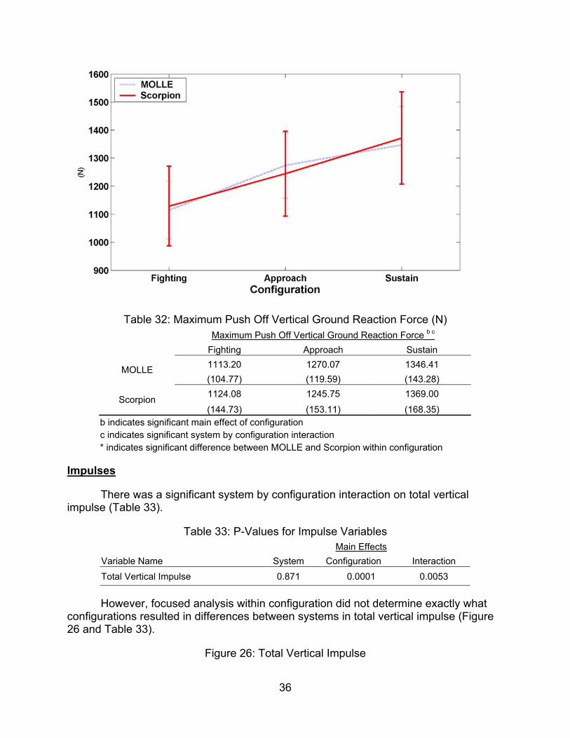
Table 32: Maximum Push Off Vertical Ground Reaction Force (N) Maximum Push Off Vertical Ground Reaction Force b c Fighting Approach Sustain
1113.20 1270.07 1346.41 MOLLE (104.77) (119.59) (143.28) 1124.08 1245.75 1369.00 Scorpion (144.73) (153.11) (168.35)
b indicates significant main effect of configuration c indicates significant system by configuration interaction * indicates significant difference between MOLLE and Scorpion within configuration
Impulses
There was a significant system by configuration interaction on total vertical impulse (Table 33).
Table 33: P-Values for Impulse Variables Main Effects Variable Name System Configuration Interaction Total Vertical Impulse 0.871 0.0001 0.0053
However, focused analysis within configuration did not determine exactly what configurations resulted in differences between systems in total vertical impulse (Figure 26 and Table 33).
Figure 26: Total Vertical Impulse
36
1600
1500
1400
1300
1200
1100
1000
900
MOLLE — Scorpion
Fighting Approach Configuration
Sustain

Table 34: Total Vertical Impulse (Ns) Total Vertical Impulse b c Fighting Approach Sustain
53127.64 60788.78 65229.07 MOLLE
(4842.39) (4749.45) (5019.14) 54032.72 59477.41 66084.57
Scorpion (6668.58) (7259.15) (7491.53)
b indicates significant main effect of configuration c indicates significant system by configuration interaction * indicates significant difference between MOLLE and Scorpion within configuration
Backpack Movement
There were significant main effects of system and configuration and a significant system by configuration interaction effect on the maximum and minimum backpack center of mass vertical position (Table 35).
Table 35: P-Values for Backpack Position Variables Main Effects Variable Name System Configuration Interaction
Maximum BPCOM Vertical Position 0.0087 0.0001 0.0001
Minimum BPCOM Vertical Position 0.0071 0.0005 0.0001
37
7.5 x10*
1
MOLLE H ■
- 7 -
-
6.5 - ^^^^-^^
-
z 6 ■ ^^ Z^^^^^^^^^^^'^^ _
^^^^^"^ *
5.5 - ^^'"'^
-
5
A K 1 '
Fighting Approach Configuration
Sustain

In the Fighting configuration, Scorpion had a slightly higher but statistically significant maximum and minimum vertical position of the backpack center of mass than MOLLE. In contrast, In the Approach configuration, MOLLE had a much (10-12%) higher maximum and minimum vertical position of the backpack center of mass than Scorpion. No statistically significant differences in vertical position of the center of mass were found between MOLLE and Scorpion in the Sustain configuration (Figures 27 and 28 and Tables 36 and 37).
Figure 27: Maximum Backpack Center of Mass Vertical Position
Table 36: Maximum Backpack Center of Mass Vertical Position (m) Maximum BPCOM Vertical Position a b c Fighting Approach Sustain
1.18 * 1.28 * 1.25 MOLLE (.05) (.06) (.09) 1.19 * 1.16 * 1.26 Scorpion (.05) (.06) (.11)
a indicates significant main effect of system b indicates significant main effect of configuration c indicates significant system by configuration interaction * indicates significant difference between MOLLE and Scorpion within configuration
Figure 28: Minimum Backpack Center of Mass Vertical Position
38
1.45
1.4
1.35
1.3
1.25
1.2
1.15-
1.1
1
MOLLE
1 r ■
1 ■
"""■'■ *"™-«iiiiii,i„ """-^lUiiiii,
""""""'■^Uiiiu,,,
-
- _ ..--'"" ^/f ̂ "^ ' jf
--_ ^ '^
; ■
1
1 . .
Fighting Approach Configuration
Sustain

Table 37: Minimum Backpack Center Of Mass Vertical Position (m) Minimum BPCOM Vertical Position a b c Fighting Approach Sustain
1.13 1.23 * 1.19 MOLLE (.05) (.06) (.09) 1.14 1.10 * 1.20 Scorpion (.05) (.06) (.11)
a indicates significant main effect of system b indicates significant main effect of configuration c indicates significant system by configuration interaction * indicates significant difference between MOLLE and Scorpion within configuration
There was a significant system by configuration interaction effect on time of maximum backpack center of mass vertical velocity, and significant main effects of system and configuration on the time of minimum backpack center of mass vertical velocity (Table 38).
Table 38: P-Values for Backpack Vertical Velocity Variables Main Effects Variable Name System Configuration Interaction Time of Maximum BPCOM Vertical
Velocity 0.0953 0.6301 0.0041
Time of Minimum BPCOM Vertical Velocity 0.0363 0.0022 0.3226
39
1.4
1.35
1.3
1.251-
I 1-2
1.151-
1.1
1.05
1
MOLLE Scorpion
Fighting Approach Configuration
Sustain

The maximum vertical velocity of the backpack center of mass occurred slightly later when walking with MOLLE Fighting than when walking with Scorpion Fighting. In contrast, the maximum vertical velocity of the backpack center of mass occurred slightly earlier when walking with MOLLE Sustain than when walking with Scorpion Sustain. No statistically significant differences the time of maximum vertical velocity of the backpack center of mass was observed in the Approach configuration (Figure 29 and Table 39)
Figure 29: Time of Maximum Backpack Center of Mass Vertical Velocity
Table 39: Time of Maximum Backpack Center of Mass Vertical Velocity (ms-1) Time of Maximum BPCOM Vertical Velocity c Fighting Approach Sustain
50.000 * 49.28 44.027 * MOLLE (22.99) (23.96) (24.43) 39.851 * 42.62 51.860 * Scorpion (22.41) (23.95) (23.38)
c indicates significant system by configuration interaction * indicates significant difference between MOLLE and Scorpion within configuration
The time of minimum vertical velocity of the backpack center of mass occurred slightly later in the stride cycle when walking with Scorpion that when walking with MOLLE (Figure 30 and Table 40).
Figure 30: Time of minimum backpack center of mass vertical velocity
40
70
65
60
„55- lU ;g
i 50
I 45 a. ^40-
35
30
25
MOLLE — Scorpion
1 ■
■ ■
p
' •
• 1
Fighting Approach Configuration
Sustain

Table 40: Time of Minimum Backpack Center of Mass Vertical Velocity (ms-1) Time of Minimum BPCOM Vertical Velocity a b Fighting Approach Sustain
85.985 72.453 62.843 MOLLE (25.834) (39.673) (42.89) 88.645 88.298 78.117 Scorpion
(24.548) (25.296) (34.19) a indicates significant main effect of system b indicates significant main effect of configuration
There was a significant main effect of configuration on maximum posterior backpack center of mass velocity, as well as a significant system by configuration interaction effect on the maximum anterior and maximum posterior backpack center of mass velocity (Table 41).
Table 41: P-Values for Backpack Horizontal Velocity Variables Main Effects Variable Name System Configuration Interaction Maximum BPCOM Anterior
Horizontal Velocity 0.6445 0.3556 0.0003
Maximum BPCOM Posterior Horizontal Velocity 0.141 0.0051 0.0001
No differences in maximum backpack anterior velocity were observed between MOLLE and Scorpion when walking with the Fighting or Sustain loads. In contrast, when walking with the Approach load, Scorpion resulted in a greater anterior horizontal
41
1 IW 1
MOLLE
100 ' '
90
1
^:^
-
(Per
cent
of
Str
ide)
o
o
o
■
1 1
50 - -
40
tn ' 1
-
Fighting Approach Configuration
Sustain

velocity than MOLLE; these differences were statistically significant (Figure 31 and Table 42).
Figure 31: Maximum Backpack Center of Mass Anterior Velocity
Table 42: Maximum Backpack Center of Mass Anterior Velocity (ms-1) Maximum BPCOM Horizontal Velocity c Fighting Approach Sustain
0.18 0.163 * 0.18 MOLLE (.03) (.04) (.05) 0.19 0.198 * 0.16 Scorpion (.05) (.03) (.04)
c indicates significant system by configuration interaction * indicates significant difference between MOLLE and Scorpion within configuration
No differences in maximum backpack posterior horizontal velocity were observed between MOLLE and Scorpion when walking with the Fighting load. In contrast, when walking with the Approach load, MOLLE resulted in a greater posterior horizontal velocity than Scorpion, while when walking with the Sustainment load, Scorpion resulted in a greater posterior velocity than MOLLE (Figure 32 and Table 43).
Figure 32: Maximum Backpack Center of Mass Posterior Velocity
42
0.24
0.22
MOLLE Scorpion
0.18-
0.16
0.14-
0.12 Fighting Approach
Configuration Sustain

Table 43: Maximum Backpack Center of Mass Posterior Velocity (ms-1) Minimum BPCOM Horizontal Velocity b c Fighting Approach Sustain
-0.169 -0.144 * -0.157 * MOLLE (.04) (.03) (.04)
-0.194 -0.183 * -0.136 * Scorpion (.04) (.03) (.04)
b indicates significant main effect of configuration c indicates significant system by configuration interaction * indicates significant difference between MOLLE and Scorpion within configuration
There was a significant main effect of system on the time of the maximum and minimum vertical acceleration of the backpack center of mass (Table 44). Walking with Scorpion resulted in a slightly earlier maximum and minimum vertical acceleration of the backpack center of mass (Figure 33 and 34 and Table 45 and 46). There was also a significant main effect of configuration on the time of the minimum vertical acceleration of the backpack center of mass.
Table 44: P-Values for Backpack Vertical Acceleration Variables Main Effects Variable Name System Configuration Interaction Time of Maximum BPCOM Vertical
Acceleration 0.0296 0.3977 0.2619
Time of Minimum BPCOM Vertical Acceleration 0.0449 0.0001 0.1658
43
-0.1
-0.12
-0.14
-0.16
-0.18
-0.2
-0.22
-0.24
1
MOLLE
1- ■ 1
- ^ -
- „.--^
,1^ ^^P"^"^ , - y"^ -
1 '
1
1
1
Fighting Approach Configuration
Sustain

Figure 33: Time of Maximum Backpack Center of Mass Vertical Acceleration
Table 45: Time of Maximum Backpack Center of Mass Vertical Acceleration (ms-2) Time of Maximum BPCOM Vertical Acceleration a Fighting Approach Sustain
62.60 59.30 54.09 MOLLE (23.12) (27.67) (28.95) 51.81 50.06 51.09 Scorpion
(29.61) (29.45) (28.55) a indicates significant main effect of system
Figure 34: Time of Minimum Backpack Center of Mass Vertical Acceleration
44
75
70
65
% 60
°55
t 50
45
40
35
MOLLE Scorpion
Fighting Approach Configuration
Sustain

Table 46: Time of Minimum Backpack Center of Mass Vertical Acceleration (ms-2) Time of Minimum BPCOM Vertical Acceleration a b Fighting Approach Sustain
74.02 74.78 75.14 MOLLE (.94) (.90) (1.09) 73.87 74.25 74.72 Scorpion (2.51) (3.92) (2.61)
a indicates significant main effect of system b indicates significant main effect of configuration
There was a significant main effect of system on the maximum anterior and posterior acceleration of the backpack center of mass, and on the time of the maximum anterior and posterior acceleration of the backpack center of mass. Additionally, there was a significant system by configuration interaction on the maximum anterior and posterior acceleration of the backpack center of mass (Table 47).
Table 47: P-Values for Backpack Horizontal Acceleration Variables Main Effects Variable Name System Configuration Interaction Maximum Anterior BPCOM
Acceleration 0.0381 0.0195 0.0017
Maximum Posterior BPCOM Acceleration 0.0264 0.0169 0.0017
Time of Maximum Anterior BPCOM Acceleration 0.0026 0.4643 0.8841
45
76
75.5
75-
m
° 74.5 c o
74
73.5-
73
1
" MOLLE '
1 ■ -
t
1
^-^^ ^^^^^
- ^^
■ ■
1 1
Fighting Approach Configuration
Sustain

Time of Maximum Posterior BPCOM Acceleration 0.0038 0.0498 0.121
In the Fighting and Approach configurations, walking with MOLLE resulted in greater maximum anterior acceleration of the backpack center of mass than Scorpion. (Figure 35 and Table 48).
Figure 35: Maximum Backpack Center of Mass Anterior Acceleration
Table 48: Maximum Backpack Center of Mass Anterior Acceleration (ms-2) Maximum BPCOM Horizontal Acceleration a b c Fighting Approach Sustain
1.892 * 1.660 * 1.881 MOLLE (.40) (.31) (.44)
2.294 * 2.145 * 1.669 Scorpion (.81) (.51) (.38)
a indicates significant main effect of system b indicates significant main effect of configuration c indicates significant system by configuration interaction * indicates significant difference between MOLLE and Scorpion within configuration
In the Approach configuration, walking with MOLLE resulted in greater maximum posterior acceleration of the backpack center of mass than Scorpion. Although it appears as though MOLLE results in a greater anterior acceleration of the backpack center of mass in the Fighting configuration, and it appears Scorpion results in a greater anterior acceleration of the backpack center of mass in the Sustainment configuration; these differences were not statistically significant (Figure 36 and Table 49).
46
2.8
2.6
MOLLE J Scorpion
2.4-
2.2-
2-
1.8-
1.6-
1.4
1.2 Fighting Approach
Configuration Sustain

Figure 36: Maximum Backpack Center of Mass Posterior Acceleration
Table 49: Maximum Backpack Center of Mass Posterior Acceleration (ms-2) Minimum BPCOM Horizontal Acceleration a b c Fighting Approach Sustain
-2.594 -2.330 * -2.490 MOLLE (.52) (.38) (.67)
-2.850 -2.995 * -2.300 Scorpion (.74) (.59) (.52)
a indicates significant main effect of system b indicates significant main effect of configuration c indicates significant system by configuration interaction * indicates significant difference between MOLLE and Scorpion within configuration
Across configurations, walking with MOLLE resulted in an earlier maximum anterior acceleration of the backpack center of mass than Scorpion (Figure 37 and Table 50).
Figure 37: Time of Maximum Backpack Center of Mass Anterior Acceleration
47
-I.O 1 . .
-2
MOLLE _ Scorpion
-2.2 - -
-2.4 ' 1
.~-^"' .,—-""""
_.-^"" ,-—"" ~~~^y^^ -
-2.8 - y^ 1
-3 '
" ^ -
-3.2
t A
~
Fighting Approach Configuration
Sustain

Table 50: Time of Maximum Backpack Center of Mass Anterior Acceleration (%stride) Time of Maximum BPCOM Horizontal Acceleration a Fighting Approach Sustain
47.42 44.10 41.55 MOLLE (38.34) (39.40) (38.96) 61.63 58.68 52.94 Scorpion
(36.51) (38.93) (39.45) a indicates significant main effect of system
Across configurations, walking with MOLLE resulted in a later maximum posterior acceleration of the backpack center of mass than Scorpion (Figure 38 and Table 51).
Figure 38: Time of Maximum Backpack Center of Mass Posterior Acceleration
48
90
80
70 IS
ieo o
1 50
40
30-
20
1
MOLLE
■
"
1
1
Fighting Approacli Configuration
Sustain

Table 51: Time of Maximum Backpack Center of Mass Posterior Acceleration (%stride) Time of Minimum BPCOM Horizontal Acceleration a b Fighting Approach Sustain
57.41 60.24 45.75 MOLLE (19.52) (16.09) (25.95) 59.66 64.46 63.52 Scorpion
(19.17) (11.73) (12.59) a indicates significant main effect of system b indicates significant main effect of configuration
METABOLIC COST
There were significant system by configuration interaction effects on oxygen consumption, carbon dioxide production, oxygen consumption/body weight, oxygen consumption/total weight, and on oxygen consumption as a percentage of baseline in addition to significant configuration main effects on all these variables (Table 52).
Table 52: P-Values for Metabolic Cost Data
Main Effects Variable Name System Configuration Interaction Oxygen Consumption (VO2) 0.737 0.0001 0.0029
Carbon Dioxide Production (VCO2) 0.6467 0.0001 0.0026
VO2/Body Weight 0.6726 0.0001 0.0042
VO2/Total Weight 0.1493 0.002 0.0023
49
ou 1
MOLLE 75 1 1 —
70 _ '
65
" 1
■
? 60
B 55 c s ^ 50
45
40 - -
35
1 1
-
Fighting Approacii Configuration
Sustain

VO2 as a Percent of Baseline 0.8780 0.0001 0.0042
Heart Rate 0.7119 0.0001 0.2536
Walking with Scorpion in the Fighting configuration resulted in 9.1% greater oxygen consumption than walking with MOLLE in the Fighting configuration. No differences were found between MOLLE Approach and Scorpion Approach, or between MOLLE Sustain and Scorpion Sustain (Figure 39 Table 53).
Figure 39: Oxygen Consumption (VO2)
Table 53: Oxygen Consumption (VO2) (mL/min) Oxygen Consumption (VO2) b c Fighting Approach Sustain
1201.54* 1384.70 1576.31 MOLLE (131.09) (143.06) (165.07) 1269.57* 1385.08 1558.13 Scorpion (171.69) (165.64) (203.05)
b indicates significant main effect of configuration c indicates significant system by configuration interaction * indicates significant difference between MOLLE and Scorpion within configuration
Walking with Scorpion in the Fighting configuration resulted in 16% greater carbon dioxide production than walking with MOLLE in the Fighting configuration. No differences were found between MOLLE Approach and Scorpion Approach, or between MOLLE Sustain and Scorpion Sustain (Figure 40 Table 54).
Figure 40: Carbon Dioxide Production (VCO2)
50
1800 MOLLE
J — Scorpion
Fighting Approach Configuration
Sustain

Table 54: Carbon Dioxide Production (VCO2) (mL/min) Carbon Dioxide Production (VCO2) b c Fighting Approach Sustain
1058.769 * 1215.30 1415.39 MOLLE (129.42) (129.06) (187.19)
1140.429 * 1230.75 1404.22 Scorpion (181.04) (177.06) (176.50)
b indicates significant main effect of configuration c indicates significant system by configuration interaction * indicates significant difference between MOLLE and Scorpion within configuration
Walking with Scorpion in the Fighting configuration resulted in 5.8% greater oxygen consumption normalized to body weight than walking with MOLLE in the Fighting configuration. No differences were found between MOLLE Approach and Scorpion Approach, or between MOLLE Sustain and Scorpion Sustain (Figure 41 Table 54).
Figure 41: Oxygen Consumption per Unit Body Mass (VO2/BM)
51
1700
1600
1500
1400
I 1300 E,
1200
1100
1000
900
1
MOLLE
1 1
- ■
[ ^^ -
_ 1
^^.^■'^'^ -
- _^
,„„--^ '
'
0^
„,.*-^
■ ■
Fighting Approach Configuration
Sustain

Table 55: Oxygen Consumption per Unit Body Mass (VO2/BM) (mL/minKg) VO2/Body Mass b c Fighting Approach Sustain
15.88* 18.30 20.86 MOLLE (1.37) (1.90) (2.61) 16.81* 18.34 20.59 Scorpion (1.84) (1.92) (2.40)
b indicates significant main effect of configuration c indicates significant system by configuration interaction * indicates significant difference between MOLLE and Scorpion within configuration
Walking with Scorpion in the Fighting configuration resulted in 7.1% greater oxygen consumption normalized by total weight than walking with MOLLE in the Fighting configuration. No differences were found between MOLLE Approach and Scorpion Approach, or between MOLLE Sustain and Scorpion Sustain (Figure 42 Table 56)
Figure 42: Oxygen Consumption Per Unit Total Mass (VO2/TM)
52
24
23
22
21
-,20
17
16
15
14
MOLLE Scorpion
,->■
Fighting Approach Configuration
Sustain

Table 56: Oxygen Consumption Per Unit Total Mass (VO2/TM) (mL/minKg) VO2/Total Mass b c Fighting Approach Sustain
11.55* 11.80 12.32 MOLLE (0.90) (1.03) (1.26) 12.38* 12.21 12.32 Scorpion (1.27) (1.14) (1.32)
b indicates significant main effect of configuration c indicates significant system by configuration interaction * indicates significant difference between MOLLE and Scorpion within configuration
There was a significant system by configuration interaction effect on oxygen consumption as a percent of baseline, however, focused analysis within configuration did not determine exactly what configurations resulted in differences between systems (Figure 43 and Table 57).
Figure 43: Oxygen Consumption as a Percent of Baseline Oxygen Consumption
53
I4 1
MOLLE
13.5 ■
1
T
13 - -
f 12.5 _ _ C
-
'
- 1 12 .^"^ __„ -—-
11.5 - —'-^'^ -
11
in R
' —
Fighting Approach Configuration
Sustain

Table 57: Oxygen Consumption as a Percent of Baseline Oxygen Consumption VO2 as a Percent of Baseline b c Fighting Approach Sustain
114.47 132.04 149.80 MOLLE (8.34) (10.71) (13.98) 120.36 131.14 147.08 Scorpion (9.71) (9.93) (11.57)
b indicates significant main effect of configuration c indicates significant system by configuration interaction
OBSTACLE COURSE
Obstacle course data for the Fighting and Approach loads were analyzed separately. For the Fighting load, there was a significant main effect of system on the time to complete the low crawl, and the time to traverse the small window. Additionally, there was a significant main effect of system on the total time to complete the obstacle course. There was a significant system by trial interaction on the time to traverse the large window (Table 64).
Table 58: P-Values for Obstacle Course - Fighting Load
Main Effects Obstacle Name System Trial Interaction Hurdles 0.6564 0.0002 0.1524
Cones 0.7373 0.0001 0.7503
Low Crawl 0.0050 0.0013 0.4444
54
170
160
150
140
130
120
110-
100
1
MOLLE
• ■
- ...^
-
' ..■"^ ̂
^*;:;:^^^ - ..■•:€iii^^^^^^ 1 .
_ ^ ^"^ -
- -
1 ■ -
Fighting Approach Configuration
Sustain

Overhead Pipe 0.2137 0.0012 0.6557
Wall 0.4034 0.2451 0.4574
Sprint 0.1202 0.0001 0.2947
Large Window 0.0953 0.5923 0.0311
Medium Window 0.6353 0.0979 0.5355
Small Window 0.0118 0.4171 0.9666
Stairs 0.5647 0.4801 0.8381
Total Time 0.0167 0.0002 0.8511
MOLLE Fighting resulted in a greater time to complete the low crawl than Scorpion Fighting (Figure 49 and Table 65).
Figure 44: Time to Complete the Low Crawl - Fighting Load
Table 59: Time to Complete the Low Crawl - Fighting Load (sec) Fighting Load Time to Complete Low Crawl a b
Pre Post 11.88 14.64 MOLLE (3.49) (2.97) 10.40 12.33 Scorpion (1.63) (1.87)
a indicates significant main effect of system b indicates significant main effect of trial * indicates significant difference between MOLLE and Scorpion within trial
55
1
17 - MOLLE ■ Scorpion
16 " "
15 -
14 - —^^^^"^^^ i p
a 13 - ^^^^-"^^^'^^ -
12 - '—'^ _——--—'—'
-
11 - ^——■ '
-
10 - -
9
o
" 1
Pre 2-Mile Post 2-Mile Trial

Before the 2-mile timed march, MOLLE Fighting resulted in a greater time to traverse the large window than scorpion Fighting, however following the 2-mile timed march, there were no statistically significant differences between MOLLE Fighting and scorpion Fighting on the time to traverse the large window (Figure 50 and Table 66).
Figure 45: Time to Traverse the Large Window - Fighting Load
Table 60: Time to Traverse the Large Window - Fighting Load (sec) Fighting Load Time to Climb Through Large Window c
Pre Post 7.56* 7.20 MOLLE (3.01) (2.39) 6.44* 7.15 Scorpion (2.35) (2.37)
c indicates significant system by trial interaction * indicates significant difference between MOLLE and Scorpion within trial
MOLLE Fighting resulted in a greater time to traverse the small window than Scorpion Fighting both before and after the 2-mile timed road march (Figure 51 and Table 67).
Figure 46: Time to Traverse the Small Window - Fighting Load
56
MOLLE Scorpion
Pre 2-Mile Post 2-Mile Trial

Table 61: Time to Traverse the Small Window - Fighting Load (sec) Fighting Load Time to Climb Through Small Window a
Pre Post
4.51 4.72 MOLLE (1.58) (1.62)
3.67 3.92 Scorpion (1.33) (1.24)
a indicates significant main effect of system
MOLLE Fighting resulted in a greater total time to traverse the obstacle course than Scorpion Fighting both before and after the 2-mile timed road march (Figure 52 and Table 68).
Figure 47: Time to Traverse Entire Obstacle Course - Fighting Load
57
6.5 1 1 1 1 1
MOLLE 6
-
— Scorpion ■
5.5 -
5 ■ 1
-
4.5 u W
4
3.5
3 - _
2.5 ( , X
2 1 1
Pre 2-Mile Post 2-Mile Trial

Table 62: Time to Traverse Entire Obstacle Course - Fighting Load (sec) Fighting Load Total Time a b
Pre Post 96.91 108.75 MOLLE
(13.69) (15.37) 91.45 102.73 Scorpion (9.90) (12.77)
a indicates significant main effect of system b indicates significant main effect of trial
For the Approach load, there was a significant main effect of system on the time to complete the low crawl, the time to traverse the medium window, and the time to run up the flight of stairs. There was a significant system by trial interaction on the time to traverse the large window (Table 69).
Table 63: P-Values for Obstacle Course - Approach Load (sec)
Main Effects Obstacle Name System Trial System by trial Hurdles 0.9289 0.0007 0.2856
Cones 0.5656 0.0001 0.6627
Low Crawl 0.0077 0.0318 0.7339
Overhead Pipe 0.0716 0.0546 0.5299
Wall 0.7274 0.8008 0.0850
58
125
120
115-
110-
105
100
95
90
85
80
1
1
1
— MOLLE
■ ■
- - ^^ ̂ ^
-
■
.u.-h'-^""
,„-—""™"" ^ ""^ -
• Pre 2-Mile Post 2-Mile
Trial

Sprint 0.7047 0.1912 0.2081
Large Window 0.3616 0.3869 0.0083
Medium Window 0.0445 0.0941 0.8519
Small Window 0.7534 0.9542 0.6338
Stairs 0.0056 0.0222 0.8478
Total Time 0.0650 0.0127 0.0549
MOLLE Approach resulted in a greater time to complete the Low Crawl than Scorpion Approach (Figure 53 and Table 70).
Figure 48: Time to Complete Low Crawl - Approach Load
Table 64: Time to Complete Low Crawl - Approach Load (sec) Approach Load Time to Complete Low Crawl a b
Pre Post 12.59 14.35 MOLLE (2.31) (1.74) 10.43 12.02 Scorpion (1.43) (1.68)
a indicates significant main effect of system b indicates significant main effect of trial
MOLLE Approach required a greater time to traverse the medium window than Scorpion Approach (Figure 54 and Table 71).
Figure 49: Time to Traverse Medium Window - Approach Load
59
17p
16
15-
14-
13'
12
11 -
10
9-
8-
MOLLE Scorpion
Pre 2-Mile Post 2-Mile Trial

Table 65: Time to Traverse Medium Window - Approach Load (sec) Approach Load Time to Climb Through Medium Window a
Pre Post 6.68 7.05 MOLLE (.93) (1.52) 6.08 6.58 Scorpion
(1.32) (1.15) a indicates significant main effect of system
MOLLE Approach resulted in a greater time to run up the flight of stairs than Scorpion Approach (Figure 55 and Table 72).
Figure 50: Time to Climb Stairs - Approach Load
60
9
8.5
8
7.5
7
6.5
6
5.5
5
4.5
1
— MOLLE
r-
1 Pre 2-Mile Post 2-Mile
Trial

Table 66: Time to Climb Stairs - Approach Load (sec) Approach Load Time to Climb Stairs a
Pre Post 12.09 11.32 MOLLE (1.23) (1.23) 11.07 10.21 Scorpion (1.11) (1.83)
a indicates significant main effect of system
Before the 2-mile timed march, MOLLE Approach resulted in a greater time to traverse the large window than scorpion Approach. However, after the 2-mile timed march, there were no statistically significant differences between MOLLE Approach and scorpion Approach on the time to traverse the large window (Figure 56 and Table 73).
Figure 51: Time to Traverse Large Window - Approach Load
61
It 1
- ■
— MOLLE
13 -
12 ■
"" "'""—-" 111-UlH„-_^_
• ■
g 11 - _^________^^
-
10 - ■
' -
9
n 1
.
Pre 2-Mile Post 2-Mile Trial

Table 67: Time to Traverse Large Window – Approach Load (sec) Approach Load Time to Climb Through Large Window c
Pre Post 7.85 * 7.22 MOLLE (2.69) (1.84) 6.36 * 7.83 Scorpion (2.86) (2.19)
c indicates significant system by configuration interaction * indicates significant difference between MOLLE and Scorpion within configuration
INDIVIDUAL MOVEMENT TECHNIQUES
There were significant main effects of system and configuration as well as a significant system by configuration interaction on "Stand to Prone", "Prone to Stand", "Doffing the Backpack", " Combat Roll", and "Donn the Backpack" (Table 58).
Table 68: P-Values for Individual Movement Techniques
Main Effects Variable Name System Configuration Interaction Stand to Prone 0.0215 0.0025 0.0271
Prone to Stand 0.0116 0.0001 0.0112
Doffing the Backpack 0.0331 0.0001 0.0118
Combat Roll 0.0145 0.0015 0.0082
Don the Backpack 0.0132 0.0001 0.0062
62
1
in — MOLLE
9 ■ -
8
- -—
"
S 7
^
6 - ' .
5 - -
4 - -
t
1 1 •
Pre 2-Mile Post 2-Mile Trial

While there was a significant main effect of system on "Stand to Prone", focused analyses indicate no difference in the time to complete the "Stand to Prone" for the Fighting load. In contrast, in the Approach configuration, subjects completed the "Stand to Prone" more quickly with Scorpion than with MOLLE (Figure 44 Table 59).
Figure 52: Stand to Prone
Table 69: Stand to Prone (sec) Time to Complete Stand to Prone a b c Fighting Approach
2.65 3.53 * MOLLE (0.56) (1.20) 2.58 2.71 *
Scorpion (0.49) (0.43)
a indicates significant main effect of system b indicates significant main effect of configuration c indicates significant system by configuration interaction * indicates significant difference between MOLLE and Scorpion within configuration
While there was a significant main effect of system on "Prone to Stand", focused analyses indicate no difference in the time to complete the "Prone to Stand" for the Fighting load. In contrast, in the Approach configuration, subjects completed the "Prone to Stand" more quickly with Scorpion than with MOLLE (Figure 45 Table 60).
Figure 53: Prone to Stand
63
9 1
MOLLE Scorpion '
- 4.5 ~
4 - -
|3.5 ^_^ -
3
:
[_^^--^^_l -
2.5
o .
Fighting Configuration
Approach

Table 70: Prone to Stand (sec) Time to Complete Prone to Stand a b c Fighting Approach
9.82 14.30 * MOLLE (1.52) (4.85) 9.03 10.53 * Scorpion
(1.20) (1.38) a indicates significant main effect of system b indicates significant main effect of configuration c indicates significant system by configuration interaction * indicates significant difference between MOLLE and Scorpion within configuration
While there was a significant main effect of system on "Doffing the Backpack", focused analyses indicate no difference in the time to complete the "Doffing the Backpack" for the Fighting load. In contrast, in the Approach configuration, subjects completed the "Doffing the Backpack" more quickly with Scorpion than with MOLLE (Figure 46 Table 61).
Figure 54: Time to Doff the Backpack
64
20
18
16-
14
12
10
8
1
MOLLE — Scorpion
■■
^-f^""
,„-HhV-^"""
,.^--^""" ^^^.jm-*""'
,,..-'-^""' _■—"■■"
1
1
■
Fighting Configuration
Approach

Table 71: Time to Doff the Backpack (sec) Time to Complete Doffing the Backpack a b c Fighting Approach
2.57 3.51 * MOLLE (0.39) (0.54) 2.49 2.90 * Scorpion
(0.37) (0.60) a indicates significant main effect of system b indicates significant main effect of configuration c indicates significant system by configuration interaction * indicates significant difference between MOLLE and Scorpion within configuration
While there was a significant main effect of system on "Combat Roll", focused analyses indicate no difference in the time to complete the "Combat Roll" for the Fighting load. In contrast, in the Approach configuration, subjects completed the "Combat Roll" more quickly with Scorpion than with MOLLE (Figure 47 Table 62).
Figure 55: Time to Complete the Combat Roll
65
4.5
4-
3.5
3-
2.5
1
MOLLE — Scorpion
-
1
1
1
...-^ „,."«^
„*"*"""' „.""-*'^"""
,.«-"^"' „„.--^
-
Fighting Configuration
Approach

Table 72: Time to Complete the Combat Roll (sec) Time to Complete Combat Roll a b c Fighting Approach
7.60 12.62 * MOLLE (1.55) (3.50) 8.07 9.88 * Scorpion
(1.39) (2.89) a indicates significant main effect of system b indicates significant main effect of configuration c indicates significant system by configuration interaction * indicates significant difference between MOLLE and Scorpion within configuration
While there was a significant main effect of system on "Donn the Backpack", focused analyses indicate no difference in the time to complete the "Donn the Backpack" for the Fighting load. In contrast, in the Approach configuration, subjects completed the "Donn the Backpack" more quickly with MOLLE than with Scorpion (Figure 48 Table 63).
Figure 56: Time to Donn the Backpack
66
lO 1
MOLLE — Scorpion
16 ~ ~
14 - -
?12 .--^
H ■
10 - ,,.*^""" -
8 """T!^ ,--^— -
Fighting Configuration
Approach

Table 73: Time to Donn the Backpack (sec) Time to Complete Don the Backpack a b c
Fighting Approach 22.42 35.17 * MOLLE
(12.95) (15.06) 22.51 54.84 * Scorpion (5.53) (20.37)
a indicates significant main effect of system b indicates significant main effect of configuration c indicates significant system by configuration interaction * indicates significant difference between MOLLE and Scorpion within configuration
Responses to Post IMT Questionnaire
After each session of IMT data collection, the subjects were asked to write down any comments they had on the system they tested that day. The following is a list of their comments, as they wrote them. Wording is transcribed as written, even as to errors in grammar and spelling.
SCORPION COMMENTS • Comfortable • Weight on hips- felt good, distribute weight well • Scorpion very comfortable. • Likes the fit, close to body, load distribution is even. • Felt more comfortable walking with Scorpion than with the MOLLE • Marching is great, no weight on back.
67
80
70
60-
50-
^40-
30-
20
10
0-
MOLLE Scorpion
Fighting Configuration
Approach

• Comfortable • Fits well all over • Likes the feel and placement better. • Chest fits good, but since it is so narrow, it pokes sides. • Maneuvers are easier. • Ammo pouches bother on left and right side. • Didn’t like the magazines in front of the chassis. • Likes where ammunition is except weapon gets stuck • Cannot shoulder weapon comfortably, vest prevents soldiers from putting the
butt of the weapon in shoulder. • Shouldering weapon is tough in stand to prone • Some shoulder strain because he had to hold the weapon more in front. • The backpack doesn’t allow the subject to aim • Difficult putting butt of weapon in shoulder • Prone: Weapon can’t be shouldered properly (helmet slides forward and hits
back) • Prone: Weapon can’t be shouldered properly; too far in or too far out • Front of vest uncomfortable. • Scorpion vest came unsnapped after first trial of Combat Roll. • Hook pin doesn’t stay, do like the pin though. • Likes the hooks, but hard to find the clips. • Pin is a pain, can’t find and doesn’t stay on • Can’t lock into place • Easy to put on pack. • Donning with snap is tough and frustrating • Donning pack- tension clips are hard for sides, good for shoulder straps,
maybe include clips like belt (have to use 2 hands) • Approach: arm went thru the shoulder pad while Donning the BP • Trouble putting on Scorpion • Easy to put on and off • Doffing and movement is good. • Easy to doff pack. • Taking off gear was easy. • In prone, keeping head up is difficult. • Can’t lift head • Hard to get into prone because stuff on the front, but able to do it. • Pack (Approach) in prone position pushes on head and hard to get in proper
shooting position. • Movement is fine- rolling is fine • No problems with Combat Roll. • Approach On Combat Roll, right shoulder strap came undone (2x) • Tailbone pad on the belt was digging into my back • Latch bar should be stationary so you don’t have to move it. • Side clips for Approach load need to be higher
68

• Pin is too low- cannot see it (need to visualize it and maybe longer) • Strap loops need to be wider. • Approach load- putting on straps is tough- but easy after practice. • Approach mode- tilt head a lot more than normal, felt comfortable. • belt easy • Ammo pouches bother on left and right side. • Likes where ammunition is except when weapon gets stuck • Didn’t like magazines in the front of Chassis • The backpack doesn’t allow subject to aim • Cannot shoulder weapon comfortably, vest prevents soldiers from putting the
butt of the weapon in shoulder. • Shouldering weapon is tough in stand to prone • Difficult putting butt of weapon in shoulder • Maybe could have a groove for weapon • Pack in prone position pushes on head and hard to get in proper shooting
position. • Prone Weapon can’t be shouldered properly (helmet slides forward and hits
back) • Prone Weapon can’t be shouldered properly; too far in or too far out • In prone, keeping head up is difficult • Approach tilt head a lot more than normal • Can’t lift head • Hard to get into prone because stuff on the front. • Vest came unsnapped after first trial of Combat Roll. • Approach On Combat Roll, right shoulder strap came undone (2x) • No problems with Combat Roll. • Movement was good, rolling was good • Doffing and movement is good. • Easy to doff pack • Taking off was good and quick • Donning pack- tension clips are hard for sides, good for shoulder straps,
maybe include clips like belt (have to use 2 hands) • Donning with snap is tough and frustrating. • Arm went thru the shoulder pad while Donning the BP • Maneuvers were easy, just difficult getting it on • Putting on straps is tough, but easy after practice • Easier to put on and off • Latch bar should be stationary so you don’t have to move it. • Pin is too low- cannot see it (need to visualize it and maybe longer) • Hook pin doesn’t stay, do like the pin though. • Likes hooks, hard to find clips but not with practice • Putting on pin is a pain; can’t find and doesn’t stay on • Can’t lock into place (but can’t in anything) • Strap loops need to be wider.
69

• Tailbone pad on the belt was digging into my back • Belt easy to use • Likes the fit, close to body, load distribution is even. • Better feel and placement • Easy to work with, slightly comfortable • Fit all over – no loose or tight spots which was good weight on hips, but felt
good (Spreads out weight well) • Side clips for Approach load need to be higher • Chest fits good; but since its narrow it pokes sides sometimes • No rubbing • Front of vest uncomfortable • Comfortable • Approach load felt comfortable
MOLLE COMMENTS • Comfortable! • Fits on body well, more mobile • Mitch helmet was better than regular helmets • Likes the vest and FLC • Very easy to get on if all connected • Very easy to get on • Likes the method of putting on MOLLE, it feels easier • Hard to get on to hips, not enough padding • Easy to put MOLLE pack on and off. • Approach pack hurt back, hip belt too hard to get off. • Too much stress on back • Back hurt a little after wearing it a long time. • Hurts back between shoulders blades • Sustained- load to heavy on mid back. • A lot harder on the back, lots of stress • Too many buckles • Too many straps. • The quick release straps on the Approach back pack are too small. • Waist strap during walking digs in • Waist belt is tough. • Approach load- putting on hip belt is hard/ can’t find it • Waist belt is a problem, can’t get it under canteens. • Chest vest to close to body, lots of pressure • Sternum strap hurt chest when secured • Vest digs into knee while kneeling • Didn’t like doing Combat Rolls during Approach mode. • Approach mode- feels off balanced when doing Combat Roll. • Frame to long, frame gets caught • Frame shape is good and comfortable.
70

• Backpack moves up when you are in prone position. • Moving side to side is no good • Grenade pocket scraped. • Approach mode, head can’t go back, no vision. • Approach- too big, floppy • Pressure on medial side of scapula • Tension in trapezoids when walking with Sustained load. • Hard to get on hips; not enough padding • Couldn’t find waist belt to get off • Waist belt – can’t see it at all • Did not like waist belt • Approach difficulty finding and putting on hip belt • Hip belt hard to get on and off • Waist belt is tough • Waist belt is a problem – can’t get it under canteens • Too many buckles • Too many straps • Seems more complicated by looks • The quick release straps on the Approach BP are too small • Quick releases are hard, don’t want it to hit back of legs • Easy to work with • Donning is easier with MOLLE • Easy to put MOLLE pack on and off • Fighting: vest easy to get on • Really like vest and FLC • Like FLC and VEST except when putting it on • FLC got tangled when donning the BP • Could make FLC and vest fit together better • Moving side to side with Approach pack was not good • Didn’t like doing Combat Rolls during Approach load • Hard to do Combat Roll with Approach load – not fast enough! • Approach load felt off balance when doing Combat Roll • Approach Combat Roll - you would get killed on your way • Never have Approach load for situation where IMT’s are done, but feasible • Makes you less effective on field due to size • ‘Ridiculous compared to SCORPION’ • Liked that you were more accessible to weapon (not as bulky) • Fits on body well, more mobility • Frame shape is good and comfortable • Good fit • Good Fighting pack • Good Approach pack once on and secure • Floppy Fighting pack • Pack does not feel secure even when it is tight
71

• Not as skin friendly • Grenade pocket scraped • Too big of a load • Too heavy • Too much stress on back was biggest complaint • Approach pack hurt back (trapezoids) • Back hurt a little after wearing a long time • Hurts back between shoulder blades • Pressure on medial side of scapula • Sternum strap hurt chest when secure • Vest digs into thigh while kneeling • Even with BDU’s on, hurt arms taking off and putting on pack • Pack doesn’t feel secure even when it is tight
Responses to Exit Survey
At the conclusion of the test, the subjects were asked a series of questions about each of the backpack systems. The following is a list of the questions asked followed by their responses.
Overall, which carrying system did you like best? • 4 MOLLE • 6 Scorpion • 1 Undecided
Like Best About Scorpion? • Uniform • Not much; but it felt lighter. • The system of the backpack is comfortable and easy to work with. • Fits securely around the body with little shifting. • Lighter load. • Overall fit and the built in pads. • It is light, more compact, less likely to get snagged on objects in different
terrain. • Less weight on shoulders. • It allows plenty of air circulation throughout the body; while still providing
plenty of tightness and sturdiness for maneuvering. • The comfort of it was great; like the weight distribution overall better with
Scorpion. • The rucksack was easier to carry with the hooks. • Vest: really easy to breathe when running and easy to adjust.
Like Best About MOLLE? • Felt good on your back and there was no discomfort on your lower back.
72

• Did not like it at all. • MICH. • Less pouches on front of vest, making it easier to hold an M16 to your
shoulder to aim at a target. • Appearance: looks a lot better than how it feels. • Nothing. • The chassis did not put as much pressure on my chest as the Scorpion did. • Pack: it always felt more snug and comfortable while maneuvering. • Pack: easy design and more mobile with it on. • Backpack as opposed to shoulder pads. • Not constricting in the chest. • Vest is more comfortable.
Dislike most about Scorpion? • Slight discomfort on the lower back. • The chassis was too tight on my chest. • Chassis was not big enough. • Too loose. • Too much weight on the lower part of your back; puts strain on your hips
because of the belt while running. • Overall design and fit of the BDU’s is too generic; allows it to shift a lot and
also makes it uncomfortable. • Connection strap for the body piece. • BDU’s. • Pack: pack would have been a lot more comfortable if it was a bit higher on
the back (or maybe it was because subject was short). • Pack. • Chassis. • Constricting air flow. • Waist pack and magazines at the front of the vest, makes it difficult to carry
the M-16.
Dislike most about MOLLE? • Shifted too much while running. • Too heavy to carry. • Never felt like it was on right. • The Approach load put a lot of strain on my left shin when I was walking. But I
would run and the pain would go away. • Too many straps that can get snagged. • Overall too snug to the body, not providing enough air circulation and it is way
too loose for maneuvering with the packs, no matter how much you tighten it • Uncomfortable: could reach the straps to tighten, at times too loose; overall
hard to adjust for comfort. • The rucksack caused too much stress on my shoulders and back. • Vest: difficult to breath and adjust at times.
73

• Nothing. • Fighting load hurt my shoulders because it didn’t have the belt. • Backpack system: is uncomfortable and too much stuff to snap.
Overall Scorpion comments • Did great in IMT and obstacle course. It was easier to do Combat Roll with
Scorpion system. The obstacle course windows were easier to move through with the Scorpion than the MOLLE. The Scorpion can improve on donning straps, so it can be more efficient.
• The scorpion was better because it was lighter to handle which could have made it faster.
• There should be a liner in the pants and chassis should be longer. • Had a great time with all the Scorpion systems. • For me it is uncomfortable to have the magazines underneath the armpits
because it tends to apply pressure to the inside portion of the bicep. • BDU’s need to be improved by providing better fit with sufficient flexibility and
overall weather adaptation. • Easy to get thru the obstacles; great suit for everything. • Scorpion was a great system for making the rucksack as light as possible. I
could tell a big difference between the weights; MOLLE was too heavy. I did not like the Scorpion chassis because it was too tight on my chest. I could not breathe too well with it on. The belt also made it more difficult to run.
• Good stuff. Great idea, just a few minor adjustments and it would be perfect. The ammunition in the front is cool, but hard to deal with while in prone. Taking it off and putting it on is a pain though.
• It was ok for rolling, but hard to disencumber and don; Two mile march was hard on lower back.
• Scorpion looks cool but feels bad. • Had a little difficulty with windows and wall; the IMT’s were very good
because of the knee and elbow pads; treadmill walking was ok; two mile road march was exhausting.
Overall MOLLE comments • MOLLE load carriage system performed the best when it came to comfort.
The flaw I noted was the shifting with the entire pack. It was also difficult to do the Combat Rolls. There are too many fasteners to undo when taking it off.
• MOLLE was too heavy. • Feels like sand paper. • Good work out; loved the windows. • The system is overall too big, too heavy, too saggy, too many straps and
clips. • Not providing sufficient benefits other than a lot of storage capabilities. • Did not like it for any of the testing.
74

• The rucksack was too heavy for carrying long distances. I thought overall it was a very poor system. The Scorpion chassis was a little better, but was still too tight on chest. In my opinion, the MOLLE should not be issued out yet in the Army.
• Good, hard to breath in vest but really good other than that. The packs are great.
• Was good in everything but Combat Rolls (the pack was too hard to roll over). • Keep it, its fine the way it is. • I had some problem with the wall and IMT’s; two mile road march and
treadmill walking were ok.
DISCUSSION
The most important differences between Scorpion and MOLLE observed in this study were in metabolic cost. Backpack mass/weight is one of the largest contributors to the metabolic cost of walking with a load. Scorpion Fighting weighed 3.8 pounds less than MOLLE Fighting. However, walking with Scorpion Fighting resulted in greater oxygen consumption, carbon dioxide production, oxygen consumption normalized to body weight, and oxygen consumption normalized by total weight than walking with MOLLE Fighting. Additionally, Scorpion Approach weighed 8.8 pounds (9%) less than MOLLE Approach. This would suggest walking with Scorpion should result in less metabolic cost than MOLLE, however, no statistically significant differences in metabolic cost were observed between Scorpion Approach and MOLLE Approach. Similarly, even though Scorpion Sustain weighed 4.4 pounds (4%) less than MOLLE Sustain, no statistically significant differences in metabolic cost were observed between MOLLE Sustain and Scorpion Sustain.
A clear conclusion from this data is that walking with Scorpion is less metabolically efficient than walking with MOLLE. The reason for this is unknown. Previous research has shown the location of the backpack center of mass is an important factor affecting the metabolic cost of load carriage. A high, relatively anterior center of mass position is more favorable in terms of reducing metabolic cost than a low, more posterior position. The backpack center of mass of Scorpion Fighting was higher and more anterior than MOLLE Fighting (approximately 1 cm higher, and 4 cm anterior). In contrast, the backpack center of mass of the Scorpion Approach was lower but more anterior than MOLLE Approach (approximately 12 cm lower, and 9 cm anterior); this may partially explain why walking with Scorpion Approach is less metabolically efficient than walking with MOLLE Approach. No differences in the height of the backpack center of mass were found between the Sustainment Loads.
Other factors that may influence metabolic cost include strap tension, the type of suspension system, internal/external frame design, etc. However, there has not been very much research performed investigating these parameters in isolation of each other; consequently, the relationship between each of these parameters and metabolic cost is unknown.
75

One factor, not previously considered, may be the corset design of the Scorpion Load Carriage System. The corset is designed to fit tightly around the subject's thorax, and may have constricted chest wall movement. One subject complained the tightness of the corset was one of the parts of Scorpion he did not like. Previous research demonstrates restricting chest wall movement during exercise can affect the function of the lungs (2), and is associated with a decrease in the amount of air that is exchanged in every breath (tidal volume), increased frequency of breathing, and increased inspired minute ventilation (9). However, data on this topic are equivocal. An additional study (13) suggests while constricting chest wall movement reduces stroke volume (the volume of blood moved with every heart beat), there is a compensatory increase in heart rate to compensate, resulting in no affect on oxygen consumption. In the present study, no statistically significant differences in heart rate were observed. Unfortunately, the present study was not designed, and therefore not equipped, to measure chest wall expansion during load carriage and to relate chest wall expansion to metabolic cost. Consequently, the present dataset will not lead to a definitive conclusion as to whether or not the corset design of the Scorpion Load Carriage System is the cause of the increased metabolic cost observed compared to MOLLE. Future research on this topic is needed.
Subjects with Scorpion performed better on some aspects of the obstacle course compared to MOLLE, however, there were no obstacles on which subjects with MOLLE performed better than Scorpion. For the Fighting Load, subjects completed the low crawl, and traversed the small window faster with Scorpion than with MOLLE (Scorpion was 16% faster for the low crawl and 21% faster for small window). Additionally, the total time to complete the obstacle course was 5.9% faster with Scorpion than with MOLLE. Similarly, Scorpion Approach resulted in a 20% shorter time to complete the low crawl, 8.5% shorter time to traverse the medium window, and 10% shorter time to run up the stairs than MOLLE Approach. Before the 2-mile timed march, MOLLE Fighting and MOLLE Approach both resulted in a greater time to traverse the large window than Scorpion Fighting and Scorpion Approach (respectively), however after the 2-mile timed march, there were no statistically significant differences between MOLLE Fighting and Scorpion Fighting or between MOLLE Approach and Scorpion Approach. This suggests the fatigue that associated with carrying Scorpion on the 2-mile march results in a greater performance decrement on the Large Window than the fatigue associated with completing the 2-mile march while carrying MOLLE. This may be the result of the decreased metabolic efficiency associated with carrying Scorpion. The Large Window may be the only obstacle this effect of fatigue is observed on may be due to the fact the subject traversed the large window just after completing a 25 M sprint, which would tax the same muscles used on the 2-mile march. An alternative explanation is that the fatigue brought about by the 2-mile march was similar in the MOLLE and Scorpion, but that the fatigue had a greater negative effect on the specific technique used for getting through the large window when wearing the Scorpion that the technique used when wearing the MOLLE.
Scorpion Fighting did not demonstrate performance advantages on the IMTs compared to MOLLE Fighting. That is, no statistically significant differences between MOLLE and Scorpion were found in "Stand to Prone", "Prone to Stand", "Doffing the
76

77
Backpack", "Combat Roll", and "Don the backpack" for the Fighting load. In contrast, Scorpion Approach resulted in performance advantages on IMTs compared to MOLLE Approach. The only IMT that subjects did not complete more quickly with Scorpion than with MOLLE was the "Donn the Backpack". For the Approach configuration, subjects completed the "Stand to Prone", "Prone to Stand", "Doffing the Backpack", and "Combat Roll", more quickly with Scorpion than with MOLLE.
Subtle differences in biomechanics were observed between MOLLE and Scorpion. Walking with Scorpion resulted in a more upright posture than walking with MOLLE. Across configurations, walking with MOLLE resulted in a greater knee flexion (smaller maximum and minimum knee flexion angle), hip extension (greater maximum hip flexion/extension angle), and less hip flexion (greater minimum hip flexion/extension angle), than walking with Scorpion. Under the Fighting load, Scorpion had a greater hip range of motion and less trunk range of motion than MOLLE. However in the Approach and Sustainment loads no differences in range of motion of the hip or trunk were found between MOLLE and Scorpion. Additionally, walking with MOLLE Fighting resulted in a greater shoulder range of motion than walking with Scorpion Fighting; however, no differences were found between MOLLE Approach and Scorpion Approach or between MOLLE Sustain and Scorpion Sustain. However, because subjects were asked to carry a mock M16 during the treadmill walking, the differences in shoulder range of motion may not necessarily be attributable to differences in backpack design.
Several differences in the timing of maximum and minimum lower limb joint angles and joint reaction forces were observed between backpack systems. The minimum knee flexion angle and maximum trunk angle both occurred slightly later in the stride cycle when walking with MOLLE than when walking with Scorpion. In contrast, the time of minimum hip flexion/extension angle, maximum ankle joint reaction force, maximum hip joint reaction force, minimum midstance vertical ground reaction force was slightly later when walking with Scorpion than when walking with MOLLE.
Scorpion Approach resulted in a greater backpack anterior velocity and a lesser backpack posterior velocity than MOLLE Approach. In contrast, Scorpion Sustain resulted in a greater posterior backpack velocity than MOLLE Sustain. In the Fighting configuration, walking with MOLLE resulted in greater maximum anterior acceleration of the backpack center of mass than Scorpion. Additionally, in the Approach configuration, walking with MOLLE resulted in greater maximum anterior and posterior acceleration of the backpack center of mass than Scorpion. Walking with Scorpion resulted in a slightly earlier maximum and minimum vertical acceleration of the backpack center of mass.
Additionally, backpack design affected the timing of the motion of the backpack. For instance, the time of minimum vertical velocity of the backpack center of mass and the maximum anterior acceleration of the backpack center of mass occurred slightly later in the stride cycle when walking with Scorpion than when walking with MOLLE. In contrast, walking with MOLLE resulted in a slightly later maximum posterior acceleration of the backpack center of mass than Scorpion. The maximum vertical velocity of the backpack center of mass occurred slightly later when walking with MOLLE Fighting than when walking with Scorpion Fighting. In contrast, the maximum vertical velocity of the

backpack center of mass occurred slightly earlier when walking with MOLLE Sustain than when walking with Scorpion Sustain.
There were several parameters that demonstrated a significant system by configuration interaction effect, however focused analysis within a configuration did not determine what configurations resulted in differences between systems. These parameters include: average ankle joint reaction force, average hip joint reaction force, time of maximum knee joint reaction force, minimum ankle joint torque, maximum push off vertical ground reaction force, total vertical impulse, VO2 as percent baseline, and time of maximum hip joint reaction force. The reason for this is unclear, however it is likely an effect of insufficient statistical power in the within configuration comparisons. When performing statistics on the entire data set (N= 2 systems x 11 subjects x 3 configurations = 66), power was great enough to detect a statistical interaction between systems (MOLLE vs. Scorpion). However in the within configuration comparisons (MOLLE Fighting vs. Scorpion Fighting, MOLLE Approach vs. Scorpion Approach, MOLLE Sustain vs. Scorpion Sustain), N was not great enough to detect statistical differences. For the within configuration comparisons, N = 2 systems x 11 subjects x 1 configuration = 22). In future experiments, increasing the number of subjects would likely address this issue.
Overall, subjects like the comfort and fit of the SLCS. Additionally, they liked that the SLCS was slightly lighter than the MOLLE, and thought the SLCS was easy to carry. In general, subjects disliked Scorpion's waist pack, thought the magazines at the front of the chassis made it difficult to carry the weapon, and thought there was too much weight carried on the lower back. Subjects liked the design of MOLLE's Fighting Load Carrier because they though it put less pressure on their chest than the SLCS chassis. Additionally, subjects liked that there were fewer pouches in the chest when carrying MOLLE (making it easier to hold and aim the weapon). Subjects disliked the lack of hip belt on the MOLLE Fighting load, found the Approach load to be uncomfortable and to move too much in relation to the body compared to the SLCS.
CONCLUSIONS
Both the MOLLE and the SLCS performed well during these tests. Subjectively, 6 of the subjects chose the SCLC as the system they liked best, 4 chose MOLLE, and 1 was undecided. The most noteworthy difference between the load carriage systems was that the Scorpion evidenced lower metabolic efficiency than the MOLLE. This is an important issue that must be addressed if Scorpion is to be implemented as an improvement over the MOLLE. One possible explanation for the decreased metabolic efficiency when walking with the SLCS is the chassis design constricted chest wall expansion. The effects of constricting chest wall expansion on metabolic cost are equivocal; more research specifically investigating this effect during load carriage is warranted. Although the SLCS is designed to be tight around the subject's chest, this effect may have been more drastic in our study because only one size chassis was available. Some of the subjects complained the chassis was too small.
78

79
Total obstacle course time with the Scorpion was shorter than with the MOLLE, both before and after the 2-mile march. Yet there was some evidence of a greater performance decrement due to the 2-mile march with the Scorpion than with the MOLLE on one of the obstacles (the large window); this may be a consequence of the decreased metabolic efficiency observed with this system. For the Fighting load, subjects traversed both the low crawl and small window faster with Scorpion than with MOLLE. Additionally, the total time to complete the obstacle course with the Fighting load was faster with Scorpion than with MOLLE. Similarly, with the Approach load, Scorpion times for the low crawl, medium window, and upstairs run were shorter than MOLLE times.
Performance differences in IMTs were also noted between MOLLE and Scorpion. The prone to stand with MOLLE Approach load took 36% more time than with Scorpion Approach. Doffing the MOLLE Approach took 21% longer than doffing Scorpion Approach. The Combat Roll took 28% longer with MOLLE Approach than with Scorpion Approach. In contrast, Scorpion Approach took 56% longer to donn than MOLLE Approach; this may be due to the pin-in-hole design of the attachment of the chassis system. Problems with this design are also noted in the subjective comments provided by the subjects: "Scorpion vest came unsnapped after first trial of Combat Roll", "Hook pin doesn’t stay, do like the pin though", "Like the hooks, but hard to find the clips".
Although important, the changes in biomechanics between systems do not indicate one system is clearly superior or inferior to the other, nor do the results of the biomechanical analyses indicate one system would result in a greater or lesser potential for injury.
REFERENCES
1. Bobet, J., and R. W. Norman. Effects of load placement on back muscle activity in load carriage. Eur J Appl Physiol Occup Physiol. 53(1): 71-75, 1984.
2. Caro, C. G., J. Butler, and A. B. DuBois. Some effects of restriction of chest cage expansion on pulmonary function in man: an experimental study. Journal of Clinical Investigation. 39: 573-583, 1959.
3. Cheney, D. Memorandum for Record, Subject: Installation visit 2-02; operational forces interface group in theater support central command's coalition forces land component command, southwest Asia; user feedback from Operation Anaconda.
4. Cohen, J. Statistical power analysis for the behavioral scienceAcademic Press, 1977.
5. Harman, E. A., P. N. Frykman, C. Pandorf, W. J. Tharion, R. P. Mello, J. P. Obusek, and J. Kirk. Physiological, biomechanical, and maximal performance comparisons of soldiers carrying loads using U.S. Marine Corps. Modular Lightweight Load-Carrying Equipment (MOLLE) and U.S. Army Modular Load System (MLS) prototypes. Natick, MA: U.S. Army Research Institute of Environmental Medicine Technical Report. T99-4.
6. Harman, E. A., P. N. Frykman, C. Pandorf, W. J. Tharion, R. P. Mello, J. P. Obusek, and J. Kirk. Physiological, biomechanical, and maximal performance comparisons of soldiers carrying loads using U.S. Marine Corps. Modular Lightweight Load-Carrying Equipment (MOLLE) with Interceptor armor and U.S. Army All Purpose Lightweight Individual Carrying Equipment (ALICE) and PASGT Body armor. Natick, MA: U.S. Army Research Institute of Environmental Medicine Technical Report. T99-9.
7. Harman, E. A., K. H. Han, P. N. Frykman, M. Johnson, F. Russel, and M. Rosenstein. The effects on gait timing, kinetics and muscle activity of various loads carried on the back. Medicine, Science, Sports and Exercise. 24(5): S129, 1992.
8. Harman, E. A., K. H. Han, P. N. Frykman, and C. Pandorf. The effects of backpack weight on the biomechanics of load carriage. Natick, MA: U.S. Army Research Institute of Environmental Medicine Technical Report. T00-17.
9. Harty, H. R., D. R. Corfield, R. M. Schwartzstein, and L. Adams. External thoracic retriction, respiratory sensation, and ventilation during exercise in men. Journal of Applied Physiology. 86(4): 1142-1150, 1999.
10. Holewijn, M. Physiological strain due to load carrying. Eur J Appl Physiol Occup Physiol. 61(3-4): 237-245, 1990.
80
11. Kinoshita, H. Effects of different load carrying systems on selected biomechanical parameters describing walking gait. Ergonomics. 28: 1347-1362, 1985.
12. LaFiandra, M., E. A. Harman, and P. N. Frykman. The effect of backpack mass on the stability of walking. Journal of Applied Biomechanics. in review.
13. Miller, J. D., K. C. Beck, M. J. Joyner, A. G. Brice, and B. D. Johnson. Cardiorespiratory effects of inelastic chest wall restriction. Journal of Applied Physiology. 92: 2419-2428, 2002.
14. Norman, R. W., and D. A. Winter. Mechanical energy analysis of human body segments during load carriage. Toronto: Defense and Civil Institute of Environmental Medicine.
15. Obusek, J. P., E. A. Harman, P. N. Frykman, C. J. Palmer, and R. K. Bills. The relationship of backpack center of mass location to the metabolic cost of load carriage. Medicine, Science, Sports and Exercise. 29(5): S205, 1997.
16. Patton, J. F., J. Kaszuba, R. P. Mello, and K. L. Reynolds. Physiological responses to prolonged treadmill walking with external loads. Eur J Appl Physiol Occup Physiol. 63(2): 89-93, 1991.
17. Pierrynowski, M. R., R. W. Norman, and D. A. Winter. Mechanical energy analyses of the human during load carriage on a treadmill. Ergonomics. 24: 1-14, 1981.
18. Quesada, P. M., L. J. Mengelkoch, R. C. Hale, and S. R. Simon. Biomechanical and metabolic effects of varying backpack loading on simulated marching. Ergonomics. 43(3): 293-309, 2000.
19. Soule, R. G., K. B. Pandolf, and R. F. Goldman. Energy expenditure of heavy load carriage. Ergonomics. 21(5): 373-381, 1978.
20. Tilbury-Davis, D. C., and R. H. Hooper. The kinetic and kinematic effects of increased load carriage upon the lower limb. Human Movement Science. 18: 693-700, 1999.
21. Winter, D. A. Biomechanics of Human Movement. New York: John Wiley and Sons, 1979.
81

APPENDIX A
GAIT PARAMETERS - ANOVA P-VALUES Main Effects Variable Name System Configuration Interaction Stride Length 0.4322 0.2225 0.2949
Stride Length/Height 0.4533 0.215 0.2889
Stride Frequency 0.1407 0.3398 0.067
Time at Toe Off 0.342 0.0001 0.104
Double Support Time 0.342 0.0001 0.104
Single Support Time 0.342 0.0001 0.104
JOINT KINEMATICS
Ankle - ANOVA p-values Main Effects Variable Name System Configuration Interaction
Maximum Ankle Flexion/Extension Angle 0.0966 0.8346 0.1682
Minimum Ankle Flexion/Extension Angle 0.0976 0.0017 0.1497
Range Ankle 0.9122 0.0008 0.9126
Time of Maximum Ankle Flexion/Extension Angle 0.6003 0.0001 0.6876
Time of Minimum Ankle Flexion/Extension Angle 0.1666 0.0072 0.515
Knee - ANOVA p-values Main Effects Variable Name System Configuration Interaction
Maximum Knee Flexion/Extension Angle 0.0063 0.1289 0.3851
Minimum Knee Flexion/Extension Angle 0.0182 0.7492 0.4538
Range Knee 0.054 0.0165 0.8879
Time of Maximum Knee Flexion/Extension Angle 0.3627 0.0001 0.248
82

Time of Minimum Knee Flexion/Extension Angle 0.0487 0.0001 0.0237
Hip Flexion/Extension - ANOVA p-values Main Effects Variable Name System Configuration Interaction
Maximum Hip Flexion/Extension Angle 0.0172 0.0001 0.946
Minimum Hip Flexion/Extension Angle 0.0058 0.0001 0.1791
Range Hip Flexion/Extension Angle 0.9486 0.0001 0.0144
Time of Maximum Hip Flexion/Extension Angle 0.0764 0.0001 0.2103
Time of Minimum Hip Flexion/Extension Angle 0.0248 0.0164 0.6654
Hip Abduction/Adduction - ANOVA p-values Main Effects Variable Name System Configuration Interaction
Minimum Hip Abduction/Adduction Angle 0.9699 0.0597 0.5292
Maximum Hip Abduction/Adduction Angle 0.4651 0.0001 0.0051
Range Hip Abduction/Adduction Angle 0.3371 0.0228 0.2833
Time of Maximum Hip Abduction/Adduction Angle 0.6548 0.1389 0.0123
Time of Minimum Hip Abduction/Adduction Angle 0.0901 0.0185 0.4827
Trunk - ANOVA p-values Main Effects Variable Name System Configuration Interaction
Maximum Trunk Angle 0.025 0.0001 0.0581
Minimum Trunk 0.0172 0.0001 0.178
Range Trunk 0.3367 0.0171 0.0075
Time of Maximum Trunk Angle 0.024 0.4113 0.8459
83

Time of Minimum Trunk 0.1248 0.3851 0.9507
Shoulder Flexion/Extension - ANOVA p-values Main Effects Variable Name System Configuration Interaction
Maximum Shoulder Flexion/Extension Angle 0.883 0.0193 0.6955
Minimum Shoulder Flexion/Extension Angle 0.9266 0.1314 0.8247
Range Shoulder Flexion/Extension Angle 0.7431 0.0005 0.0279
Time of Maximum Shoulder Flexion/Extension Angle 0.3684 0.0103 0.1007
Time of Minimum Shoulder Flexion/Extension Angle 0.2848 0.2378 0.7411
Shoulder Abduction/Adduction - ANOVA p-values Main Effects Variable Name System Configuration Interaction Maximum Shoulder Abduction/Adduction
Angle 0.9803 0.7711 0.609
Minimum Shoulder Abduction/Adduction Angle 0.9863 0.7768 0.6373
Range Shoulder Abduction/Adduction Angle 0.9596 0.9431 0.4681
Time of Maximum Shoulder Abduction/Adduction Angle 0.6925 0.0596 0.4588
Time of Minimum Shoulder Abduction/Adduction Angle 0.8146 0.1557 0.5012
LOWER LIMB JOINT REACTION FORCES:
Ankle - ANOVA p-values Main Effects Variable Name System Configuration Interaction
Maximum Ankle Resultant Force 0.8388 0.0001 0.3693
Maximum Ankle Resultant Force/Total Load 0.3545 0.2288 0.8976
Time of Maximum Ankle Resultant Force 0.006 0.1711 0.2366
84

Average Ankle Resultant Force 0.8878 0.0001 0.0058
Average Ankle Resultant Force/Total Load 0.3151 0.5906 0.1512
Knee - ANOVA p-values Main Effects Variable Name System Configuration Interaction
Maximum Knee Resultant Force 0.8438 0.0001 0.441
Maximum Knee Resultant Force/Total Load 0.384 0.2077 0.9267
Average Knee Resultant Force 0.943 0.0001 0.0067
Time of Maximum Knee Resultant Force 0.0075 0.0569 0.3308
Average Knee Resultant Force/Total Load 0.3562 0.5101 0.1544
Hip - ANOVA p-values Main Effects Variable Name System Configuration Interaction
Maximum Hip Resultant Force 0.9009 0.0001 0.5349
Maximum Hip Resultant Force/Total Load 0.4113 0.1369 0.9617
Time of Maximum Hip Resultant Force 0.0054 0.2075 0.4111
Average Hip Resultant Force 0.9733 0.0001 0.0099
Average Hip Resultant Force/Total Load 0.39 0.183 0.2208
LOWER LIMB JOINT TORQUES:
Ankle - ANOVA p-values Main Effects Variable Name System Configuration Interaction
Maximum Ankle Joint Torque 0.426 0.0001 0.997
Minimum Ankle Joint Torque 0.9207 0.0001 0.0302
85

Time of Maximum Ankle Joint Torque 0.6802 0.0001 0.5905
Time of Minimum Ankle Joint Torque 0.8624 0.2309 0.9402
Knee - ANOVA p-values Main Effects Variable Name System Configuration Interaction
Maximum Knee Joint Torque 0.8572 0.0001 0.3937
Minimum Knee Joint Torque 0.2574 0.0006 0.9814
Time of Maximum Knee Joint Torque 0.7515 0.034 0.0849
Time of Minimum Knee Joint Torque 0.8169 0.0001 0.4918
Hip - ANOVA p-values Main Effects Variable Name System Configuration Interaction
Maximum Hip Joint Torque 0.2154 0.0001 0.7617
Minimum Hip Joint Torque 0.1311 0.0342 0.8589
Time of Maximum Hip Joint Torque 0.127 0.4951 0.3681
Time of Minimum Hip Joint Torque 0.4569 0.0001 0.3044
GROUND REACTION FORCE VARIABLES:
Vertical - ANOVA p-values Main Effects Variable Name System Configuration Interaction Maximum Heel Strike Vertical Ground
Reaction Force 0.4699 0.0001 0.5258
Maximum Heel Strike Vertical Ground Reaction Force/Total Load 0.6987 0.0226 0.5943
Time of Maximum Heel Strike Vertical Ground Reaction Force 0.3487 0.7545 0.612
Minimum Midstance Vertical Ground Reaction Force 0.8799 0.0001 0.323
86

Minimum Midstance Vertical Ground Reaction Force/Total Load 0.3061 0.2247 0.8898
Time of Minimum Midstance Vertical Ground Reaction Force 0.0068 0.224 0.1634
Maximum Push Off Vertical Ground Reaction Force 0.8879 0.0001 0.0295
Maximum Push Off Vertical Ground Reaction Force/Total Load 0.2067 0.182 0.3996
Time of Maximum Push Off Vertical Ground Reaction Force 0.3269 0.0683 0.317
Anterior-Posterior (Forward/Backward) - ANOVA p-values Main Effects Variable Name System Configuration Interaction Maximum Heel Strike Braking Ground
Reaction Force 0.128 0.8494 0.6182
Maximum Heel Strike Braking Ground Reaction Force/Total Load 0.1137 0.1666 0.5441
Time of Maximum Heel Strike Braking Ground Reaction Force 0.8124 0.9273 0.103
Maximum Push Off Propulsive Ground Reaction Force 0.0649 0.6077 0.5129
Maximum Push Off Propulsive Ground Reaction Force/Total Load 0.0579 0.7126 0.4587
Time of Maximum Push Off Propulsive Ground Reaction Force 0.6849 0.504 0.4538
Lateral - ANOVA p-values Main Effects Variable Name System Configuration Interaction Maximum Heel Strike Lateral Ground
Reaction Force 0.5718 0.0001 0.3551
Maximum Heel Strike Lateral Ground Reaction Force/Total Load 0.8408 0.0011 0.4753
Time of Maximum Heel Strike Lateral Ground Reaction Force 0.4353 0.452 0.4067
Maximum Push Off Lateral Ground Reaction Force 0.5324 0.8565 0.5723
Maximum Push Off Lateral Ground Reaction Force/Total Load 0.4 0.2758 0.7367
Time of Maximum Push Off Lateral Ground Reaction Force 0.1034 0.5163 0.4
87

Torque between Foot and Ground - ANOVA p-values Main Effects Variable Name System Configuration Interaction Maximum Ground Reaction Moment around
Vertical Axis 0.1563 0.0001 0.794
Time of Maximum Ground Reaction Moment around Vertical Axis 0.7501 0.0001 0.5887
Minimum Ground Reaction Moment around Vertical Axis 0.4268 0.138 0.1864
Time of Minimum Ground Reaction Moment around Vertical Axis 0.2179 0.6543 0.4987
IMPULSES - ANOVA P-VALUES Main Effects Variable Name System Configuration Interaction Total Vertical Impulse 0.871 0.0001 0.0053
Average Vertical Impulse 0.0673 0.0001 0.4254
Average Vertical Impulse/Total Load 0.8605 0.0001 0.9203
Total Braking Impulse 0.2064 0.2775 0.8558
Average Braking Impulse 0.3692 0.417 0.3513
Braking Average/Total Load 0.453 0.1556 0.3438
Total Propulsive Impulse 0.1058 0.8245 0.3827
Average Propulsive Impulse 0.1055 0.8648 0.3812
Propulsive Average/Total Load 0.0988 0.5485 0.3446
Total Medial Impulse 0.361 0.0001 0.3121
Average Medial Impulse 0.1068 0.0001 0.8433
Medial Average/Total Load 0.2013 0.9815 0.9815
Total Lateral Impulse 0.9144 0.0001 0.1394
Average Lateral Impulse 0.265 0.0001 0.9261
Lateral Average/Total Load 0.4067 0.0515 0.8832
BACKPACK MOVEMENT
Vertical Position - ANOVA p-values Main Effects Variable Name System Configuration Interaction
88

Maximum BPCOM Vertical Position 0.0087 0.0001 0.0001
Minimum BPCOM Vertical Position 0.0071 0.0005 0.0001
Range BPCOM Vertical Position 0.8641 0.0001 0.1826
Time of Maximum BPCOM Vertical Position 0.5142 0.8993 0.5158
Time of Minimum BPCOM Vertical Position 0.228 0.045 0.3688
Vertical Velocity - ANOVA p-values Main Effects Variable Name System Configuration Interaction
Maximum BPCOM Vertical Velocity 0.4737 0.0001 0.5193
Minimum BPCOM Vertical Velocity 0.4561 0.0001 0.0732
Time of Maximum BPCOM Vertical Velocity 0.0953 0.6301 0.0041
Time of Minimum BPCOM Vertical Velocity 0.0363 0.0022 0.3226
Horizontal Velocity - ANOVA p-values Main Effects Variable Name System Configuration Interaction
Maximum BPCOM Horizontal Velocity 0.6445 0.3556 0.0003
Minimum BPCOM Horizontal Velocity 0.141 0.0051 0.0001
Time of Maximum BPCOM Horizontal Velocity 0.5024 0.0689 0.5808
Time of Minimum BPCOM Horizontal Velocity 0.1093 0.6548 0.6644
Vertical Acceleration - ANOVA p-values Main Effects Variable Name System Configuration Interaction
Minimum BPCOM Vertical Acceleration 0.4191 0.0004 0.5117
Maximum BPCOM Vertical Acceleration 0.1846 0.0003 0.2272
89

90
Time of Maximum BPCOM Vertical Acceleration 0.0296 0.3977 0.2619
Time of Minimum BPCOM Vertical Acceleration 0.0449 0.0001 0.1658
Horizontal Acceleration - ANOVA p-values Main Effects Variable Name System Configuration Interaction
Maximum BPCOM Horizontal Acceleration 0.0381 0.0195 0.0017
Minimum BPCOM Horizontal Acceleration 0.0264 0.0169 0.0017
Time of Maximum BPCOM Horizontal Acceleration 0.0026 0.4643 0.8841
Time of Minimum BPCOM Horizontal Acceleration 0.0038 0.0498 0.121
BACKPACK – BODY DISTANCE PARAMETERS - ANOVA P-VALUES Main Effects Variable Name System Configuration Interaction Average Vertical Distance Between Body
COM and BP COM 0.9491 0.7622 0.8981
STD Horizontal Distance Between Body COM and BP COM (m) 0.9804 0.0001 0.4034
STD Vertical Distance Between Body COM and BP COM 0.6884 0.0048 0.828