usb snes gamepad - adafruit industries · overview this project tutorial will show you how you can...
TRANSCRIPT
USB SNES GamepadCreated by lady ada
Last updated on 2019-04-25 06:15:17 PM UTC

Overview
This project tutorial will show you how you can convert a console game pad into a USB keyboard mouse for playinggames on your PC. The USB game pad can be used with nearly any software, such as a MAME emulator, game,simulation software, or for custom user interfaces.
We'll start by turning the buttons of the game pad into keyboard buttons, so that pressing 'up' is converted into the 'U'key, for example. The firmware is easily adaptable, so you can adjust it for whatever software it will be used with.
Then we'll make the project more interesting by adding an accelerometer. This will allow the game pad to be used asa mouse by tilting it!
This tutorial including the original code and Portal video is by Devlin Thyne (https://adafru.it/aL2)! Rock!
© Adafruit Industries https://learn.adafruit.com/usb-snes-gamepad Page 3 of 27

What you'll need:
You'll need the following in order to build the project:
Game Pad Controller (http://adafru.it/131) - We'll be using an SNES ControllerTeensy (http://adafru.it/199) - This is a very small microcontroller board that can act as a keyboard/mouseTriple-axis accelerometer (http://adafru.it/163) - We'll be using the nice ADXL335 on a breakout board. You canskip this if you're not planning to add in the mouse capabilityUSB cable with mini-b connector (http://adafru.it/260) - to attach to the Teensy for plugging into a computer!Ribbon cable - for all the soldering connections. Rainbow cable is the easiest to work with as its color coded
If you want to build the entire project, we have a project pack in the shop with all the parts listedabove! (http://adafru.it/241)
You'll also need some basic hand tools such as screwdrivers, wire strippers, soldering iron (http://adafru.it/180),solder (http://adafru.it/145), diagonal cutters (http://adafru.it/152), vise or third hand tool, etc.
All the code is on GitHub, including some extra sketches we've written (https://adafru.it/EDx) so be sure to look there!
© Adafruit Industries https://learn.adafruit.com/usb-snes-gamepad Page 4 of 27

Disassemble the SNES Controller
We'll begin by disassembling the SNES controller.
There are 5 small phillips screws on the back. Once you
lift the back off, you can remove the PCB. Be careful as
there are tiny wires for the 'side' buttons so just make
sure those pieces come out cleanly.
© Adafruit Industries https://learn.adafruit.com/usb-snes-gamepad Page 5 of 27

Each button is made of 3 parts - theres the plastic part
that you press, beneath that is the elastomer which is a
rubber molded piece with a conductive bit that goes
underneath the plastic part, and finally on the PCB there
are two interdigitated and exposed traces. When the
user presses the plastic button, it pushes down on the
elastomer which then pushes the conductive rubber
onto both traces, shorting them.
There is also a black blob in the middle. This blob is a
chip that takes all the button inputs and then converts it
into the way that the SNES wants to hear. Thats all fine,
but we dont want to use the blob because we are going
to make our own custom chip software. (Note that it
would be pretty easy to make the Teensy 'talk' right to
the blob using the SNES protocol but then you wouldn't
be able to adapt this tutorial to other controllers, for that
reason we're going to do it the 'hard way')
The question is now how can we listen to all the
buttons?
Well, luckily, almost all game pads are going to use a similar method for arranging the buttons. If you note carefully atthe PCB, you'll see that each button is made of two traces, but that all of the buttons share one trace together.
This is the common (ground) trace. If we were to make a schematic, it would look kinda like this:
© Adafruit Industries https://learn.adafruit.com/usb-snes-gamepad Page 6 of 27

Note that this is really just a symbolic schematic, the ground wire doesn't necessarily connect on the side thatsindicated, we're just showing how all the buttons have a common ground pin!
OK now this is straight forward, if you are not sure how to read buttons with a microcontroller, we have a nice tutorialyou might want to check out (https://adafru.it/aL4) (in fact, we really suggest it as we'll be referring to concepts in thattutorial) Basically each button connects to an input of the microcontroller. We'll need a pull-up resistor, but luckily wecan set the microcontroller's internal pullups (so we dont have to solder in 12 10K resistors!) Then the microcontrollercan listen on each pin for a button press and when it is received, generate a keypress event.
© Adafruit Industries https://learn.adafruit.com/usb-snes-gamepad Page 7 of 27

Introducing the Teensy with HID
So you may be wondering "heck, I should just grab an Arduino!" But a 'proper' Arduino can't do what we want, which isto appear as a keyboard. When you plug in an Arduino into your USB port, it shows up as a Serial device, which isfantastic for debugging or for interfacing to Processing. To listen to a Serial device, you need to open up Hyperterm orZterm or the Arduino IDE's serial monitor. However, it does not act as actual keyboard where what it outputs goes toMicrosoft Word or a video game.
The Arduino is a USB serial port - it appears under Ports here, not under Keyboards!
For that, we need a different kind of chip, a chip that is USB native! USB native chips can act as USB serial ports, butthey can also act as MIDI devices, keyboards, mice, audio devices, joysticks, etc. Nearly anything! A nice chip that doesall this is the ATmega32U4 (the U is for usb!) .
The Teensy (https://adafru.it/EDy) 2.0 is basically this chip, a USB connector, button and some other necessary things.It's very tiny (thus the name) and has a fantastic programming interface that is basically the Arduino + a helper, it runsunder Mac, Linux or Windows (https://adafru.it/aL5).
Since this tutorial was written, a number of other 32U4 microcontroller boards have been developed including thelarge Arduino Leonardo and the smaller Adafruit ItsyBitsy 32u4 - 5V 16MHz (https://adafru.it/Cmx), Adafruit ItsyBitsy32u4 - 3V 8MHz (https://adafru.it/BjC), and Adafruit Feather 32u4 Basic Proto (https://adafru.it/keL), which can dosimilar things.
© Adafruit Industries https://learn.adafruit.com/usb-snes-gamepad Page 8 of 27

© Adafruit Industries https://learn.adafruit.com/usb-snes-gamepad Page 9 of 27

Assemble the Gamepad
OK we're basically ready to go. The plan is to solder a single Ground wire to the common ground for all the buttons,then solder a seperate wire to each button (the not-ground side). The ground connects to the Teensy ground, thebutton wires connect to all the solder pads down the side. Then we'll write the code that listens to the button pressesand converts them.
Cut off a strip of ribbon cable, about 4" long. Use
diagonal cutters or fingernails to carefully nip and 'rip'
the individual wires apart about 1" and then strip the
ends and tin them with solder. Do this for both sides.
I made this cable about 1" too long initially, but its always
easy to make the cable shorter!
© Adafruit Industries https://learn.adafruit.com/usb-snes-gamepad Page 10 of 27
To connect to ground, we'll expose a little copper in the
top left corner, this way we don't have the wire running
underneath the elastomer.
© Adafruit Industries https://learn.adafruit.com/usb-snes-gamepad Page 11 of 27

Solder the Black wire to the ground plane, we brought
the wire through a hole.
© Adafruit Industries https://learn.adafruit.com/usb-snes-gamepad Page 12 of 27

OK lets solder to the first button. The key is to
remember to NOT solder to the same common pad but
to the opposite pad! Solder the white wire to the 'up'
button. There's almost always a hole you can feed the
wire through!
Solder the gray wire to the Right pad, the purple wire to
the Down pad and the blue wire to the Left pad.
From the back.
© Adafruit Industries https://learn.adafruit.com/usb-snes-gamepad Page 13 of 27

Then the orange wire goes to the L1 button, the yellow
goes to Start and the green to Select.
© Adafruit Industries https://learn.adafruit.com/usb-snes-gamepad Page 14 of 27

I didnt end up using the Red or Brown wires so I tore
those off the ribbon. Now cut another piece the same
size but with only the white, gray, purple, blue and
green wires.
Connect white to B, gray to A, purple to X, blue to Y and
green to R1.
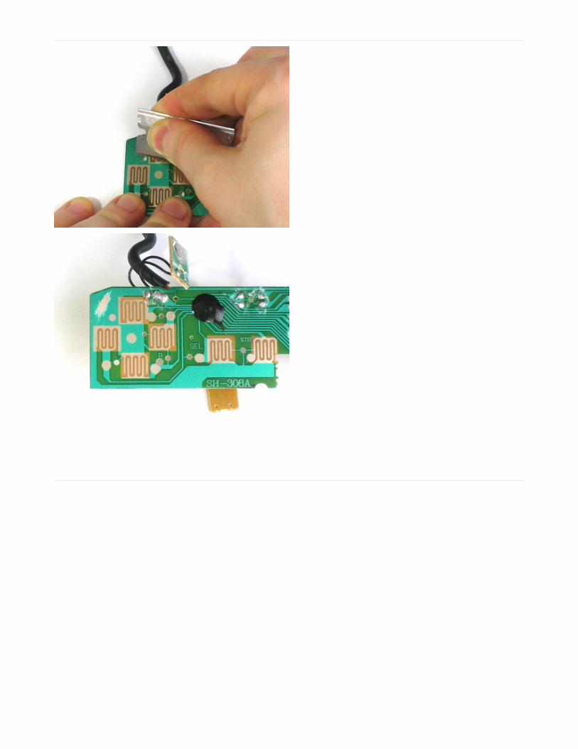
If you haven't yet, now is a good time to desolder the
SNES connector cable. We wont have space for it so just
pull each wire as you heat the solder joint (or just cut
them short, either way).
© Adafruit Industries https://learn.adafruit.com/usb-snes-gamepad Page 15 of 27
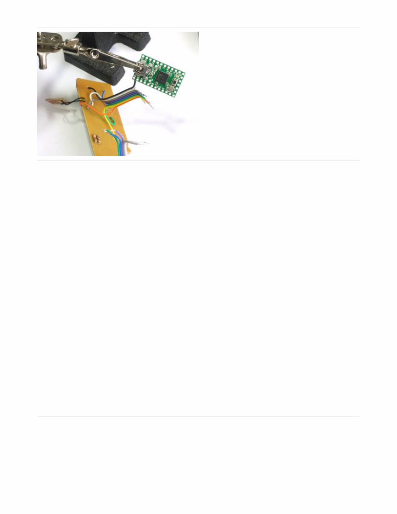
OK! Now all the buttons are wired up, its time to attach
them to the Teensy. Place the Teensy in a vise or
carefully use a 'third hand' to hold it (grab by the USB
connector).
First, solder the black wire to the ground pin.
Next start soldering in all the ribbon cable wires, one
after the other, without skipping any holes.
© Adafruit Industries https://learn.adafruit.com/usb-snes-gamepad Page 16 of 27
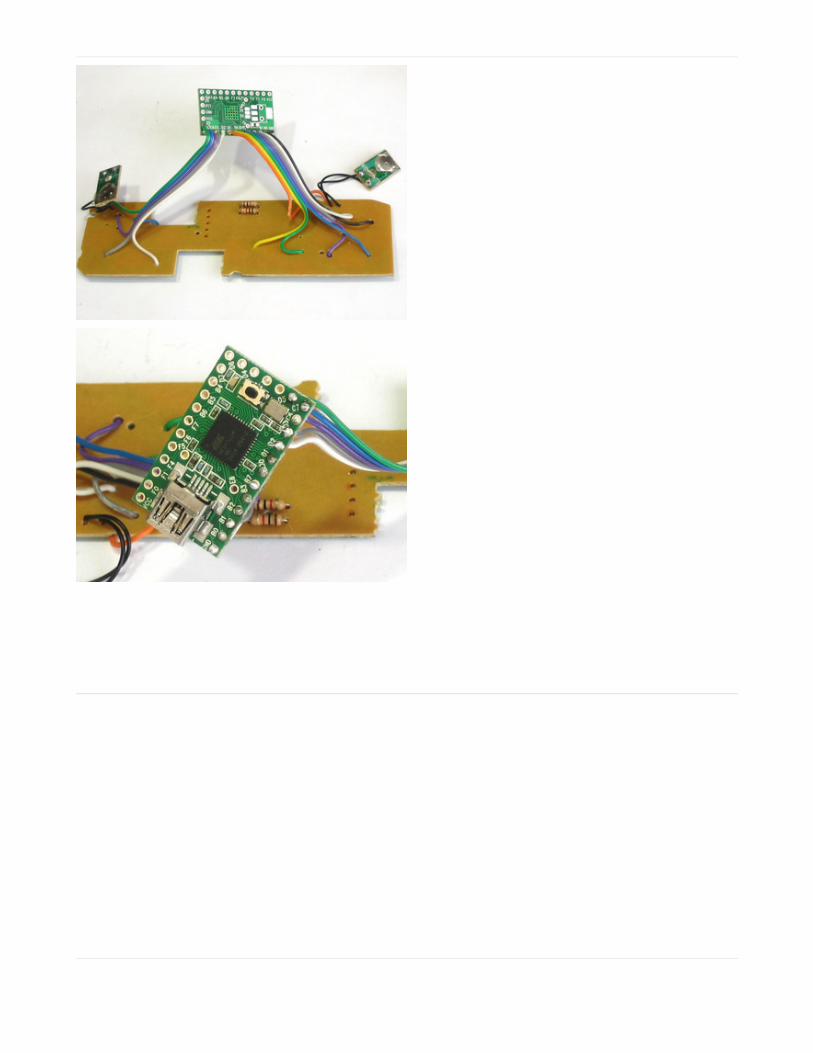
After the first ribbon cable, go to the second piece,
starting with the white wire. The last green wire goes
next to the blue one on the 'short' side.
Now we are ready to upload code to the Teensy and
test out our work!
© Adafruit Industries https://learn.adafruit.com/usb-snes-gamepad Page 17 of 27

© Adafruit Industries https://learn.adafruit.com/usb-snes-gamepad Page 18 of 27

Programming the Teensy
The Teensy uses the USB connection for programing, so we don't need a seperate AVR programmer. We will use theTeensyduino IDE, which is a patch to the Arduino IDE.
If you don't have it yet, download & install the Arduino IDE software (https://adafru.it/aL6)
Next, download the Teensyduino installer for your OS and run it, patching the Arduino IDE (https://adafru.it/aL7)
Finally, be sure to also grab Teensyloader (https://adafru.it/aL8) which is a helper that talks to the Teensy for you.
One Button Test
We'll start with the 'one button test' sketch, which will only listen for the 'Up' D-Pad button and output the letter 'u'
Understanding this code now will make it a lot easier to understand the later sketches that are much more complex!
You can also grab this code (which may be updated!) at GitHub (https://adafru.it/EDC)
Now we'll upload this sketch to the Teensy. Make a new sketch and copy the code in. Select the Teensy 2.0 (USBKeyboard/Mouse) item from the Board menu.
Make sure the Loader is running, if you see this:
Temporarily unable to load content:
© Adafruit Industries https://learn.adafruit.com/usb-snes-gamepad Page 19 of 27

Press the tiny button to start the bootloader, so that it looks like this:
Upload the sketch! You should see it sucessfully program the Teensy, and reboot. The OS will then alert you that itfound an HID device.
And the device manager will now have an extra Keyboard and Mouse called "HID Keyboard Device" and "HID-compliant mouse"
© Adafruit Industries https://learn.adafruit.com/usb-snes-gamepad Page 20 of 27

You should now be able to open up a text editor and carefully push the 'up' D-pad to generate 'u's!
All Button Test
Next we can upload the sketch that uses all the buttons so you can test each connection. It is much longer. Downloadit from GitHub (https://adafru.it/EDD).
You should test all the buttons, to make sure they all output characters.
This code is more involved since it has to listen to 12 buttons. You can see at the top where we define an array of allthe buttons, and then the keys that correspond to the presses. In this case, we're using a simple one-to-onecorrespondence for keypresses, such as Up being 'u'. To adapt this code to allow for things like "Alt-F3" would be alittle more complex.
The code supports up to 6 simultaneous keypresses.
Temporarily unable to load content:
© Adafruit Industries https://learn.adafruit.com/usb-snes-gamepad Page 21 of 27

© Adafruit Industries https://learn.adafruit.com/usb-snes-gamepad Page 22 of 27

Adding the Accelerometer
Now we will add in the accelerometer to create a tilt-activated mouse. Nearly any accelerometer will do, but theeasiest to use is an analog output one. The ADXL335 will work great. First we will power the chip by providing 3.3V(not 5.0V) and ground from the Teensy, then connect the three analog outputs (X Y and Z) to three analog inputs.Finally, we will add Mouse'ing code to the sketch so that Mouse movement events are sent when the controller istilted.
Cut a piece of ribbon cable down, we'll use Brown for
Ground, Red for +3V, then Orange Yellow and Green for
X Y and Z respectively.
We tore the brown wire off so that it wouldnt be twisted.
The ADXL335 requires 3V power, so don't connect it to
VCC (5V) instead, we'll use the 3V that the teensy
provides - it uses that voltage for the USB
communication, you can't draw more than maybe 20-
40mA which is plenty for this but not enough for
perhaps a bunch of LEDs! Brown connects to the
second GND pin.
© Adafruit Industries https://learn.adafruit.com/usb-snes-gamepad Page 23 of 27

Next connect X Y and Z to F5, F4 and F1 (don't use F0!)
You should now try out the next sketch, teensySNES_test2.ino (https://adafru.it/EDE) which will move the mouse asyou tilt the controller.
Temporarily unable to load content:
© Adafruit Industries https://learn.adafruit.com/usb-snes-gamepad Page 24 of 27

Closing itUp
Now that the mouse and keyboard are working, we can close up the game pad. This is actually the toughest part ofthe project, as the enclosure has plastic standoffs that are in the way.
One thing that will help is 'deribboning' the ribbon cable,
so that it is easy to push around the wires.
Use sticky foam tape or hot glue to place the Teensy
right at the top.
© Adafruit Industries https://learn.adafruit.com/usb-snes-gamepad Page 25 of 27

Likewise, align the acellerometer so that it is as shown
(otherwise you may have some flipped axes. You should
put it near the middle but we didn't see any difference
being in this location.
Finally, twist the USB cable so that it goes through the
strain relief posts. If this makes it really tough to close
you can probably skip it and just be careful not to yank!
As you close the case, use tweezers to poke the wires around inside so that they do not interfere with the standoffs.
We wanted to make sure we could update the code without going through the disassembly process, so we drilled ahole in the back right over where the button is, then used a paper clip to push the tiny button. You can also just soldertwo wires to GND and RST and bring these out of the case, when shorted it will start the bootloader.
© Adafruit Industries https://learn.adafruit.com/usb-snes-gamepad Page 26 of 27

You're done! Enjoy your new toy, and modify the sketch if you need to change the key commands or mousemovements.
© Adafruit Industries Last Updated: 2019-04-25 06:15:17 PM UTC Page 27 of 27