use of acoustic emission to monitor progressive … · programmed tensile stress schedules were...
TRANSCRIPT

USE OF ACOUSTIC EMISSION TO MONITOR PROGRESSIVEDAMAGE ACCUMULATION IN KEVLAR`R' 49 COMPOSITES
J. M. Waller', R. L. Saulsberry2 , and E. Andrade3
'Materials Scientist, NASA Johnson Space Center White Sands Test Facility, LaboratoriesDepartment, MS 200LD, Las Cruces, New Mexico 88011
2Project Manager, NASA Johnson Space Center White Sands Test Facility, LaboratoriesDepartment, MS 200LD, Las Cruces, New Mexico 88011.
3USRP Intern, Department of Metallurgical and Materials Engineering; University of Texasat El Paso, Texas 79968
ABSTRACT. Acoustic emission (AE) data acquired during intermittent load hold tensile testing ofepoxy impregnated Kevlar'^ 49 (K/Ep) composite strands were analyzed to monitor progressive damageduring the approach to tensile failure. Insight into the progressive damage of K/Ep strands was gainedby monitoring AE event rate and energy. Source location based on energy attenuation and arrival timedata was used to discern between significant AE attributable to microstructural damage and spurious AEattributable to noise. One of the significant findings was the observation of increasing violation of theKaiser effect (Felicity ratio < 1.0) with damage accumulation. The efficacy of three differentintermittent load hold stress schedules that allowed the Felicity ratio to be determined analytically isdiscussed.
Keywords: Acoustic emission: nondestructive evaluation; Kaiser effect: Felicity ratio, COPVPACS: 43.40.Le Techniques for nondestructive evaluation and monitoring, acoustic emission
INTRODUCTION
Composite Overwrapped Pressure Vessels (COPVs) are widely used in launchvehicles and satellites, where the strong drive to reduce weight has pushed COPV designersto adopt high performance, high specific strength composite materials with a relatively highvolume fraction (vf z:^ 0.6 to 0.7) of fiber. To date, the composite materials used in COPVdesigns have typically consisted of aramid or carbon fiber embedded in a thermoset matrixsuch as epoxy. The role of the matrix is to transfer pressurization load to the fiber, whilethe role of the fiber is to withstand the load over time under the environmental exposureconditions encountered in service. Pressurizations on the order of 350 to 700 bar (5000 to
https://ntrs.nasa.gov/search.jsp?R=20090026552 2020-06-02T03:29:09+00:00Z
10,000 psi) are common for COPVs. This has necessitated the use of high load bearingcomposite overwraps wound around a thin-walled metal liner.
NASA has been faced with recertification and life extension issues for epoxyimpregnated Kevlar9 49 (K/Ep) COPVs distributed throughout various systems on theSpace Shuttle Orbiter. The Shuttle COPVs have varying criticality, usage histories, damageand repair histories, time at pressure, and number of pressure cycles. The originalcertification for Shuttle COPVs was for 10 years, which was later extended to 20 years.Currently, Shuttle COPVs operating without certification are being flown on waiver. Also,K/Ep COPVs like those used on the Shuttle are of particular concern due to the insidiousand catastrophic "burst-before-leak" (BBL) failure mode caused by stress rupture (SR) ofthe composite overwrap. SR life has been defined by the American Institute forAeronautics and Astronautics (AIAA) Aerospace Pressure Vessels Standards WorkingGroup as "the minimum time during which the composite maintains structural integrityconsidering the combined effects of stress level(s), time at stress level(s), and associatedenvironment" [1]. SR has none of the features of predictability associated with metalpressure vessels, such as crack geometry, growth rate and size, or features that lendthemselves to the use of nondestructive evaluation (NDE) methods. In essence, thevariability or "surprise factor" associated with SR in K/Ep COPVs cannot be eliminated.
For these reasons, NASA has devoted much effort to develop NDE methods thatcan be used during post-manufacture qualification, in-service inspection, and in situstructural health monitoring. One of the more promising NDE techniques for detecting andmonitoring, in real-time, the strain energy release and corresponding stress-wavepropagation produced by actively growing flaws and defects in composite materials isacoustic emission (AE) [2, 3, 4, 5, 6, 7, 8, 9]. It is hoped that the procedures described inthis paper lay the groundwork for establishing critical thresholds for accumulated damagein composite structures such as COPVs so that precautionary or preemptive engineeringsteps can be implemented to minimize or obviate the risk of catastrophic failure of thosestructures.
EXPERIMENTAL
Tensile Tester
Programmed tensile stress schedules were applied using an Instron® 5569 SeriesElectromechanical Test Instrument equipped with a 50 kN (11,200 lb f) capacity load cell.Other features included self-tightening 25 x 50 mm (1 x 2 in.) wedge action mechanicalgrips, and a Windows compatible Bluehill ® (version 1.8.289). To minimize excessive AEduring loading and unloading ramps, a 20 N/min (4.5 lb f/min) loading/unloading rate wasused, consistent with the ASTM E 1118 [10] recommendation that the load rate should notexceed 5 percent per minute of the desired highest stress (in this case, the ultimate tensilestrength (UTS)). To prevent saturation of the Bluehill® data acquisition buffer, a 1 to 2 s-1
data acquisition rate was used, depending on the duration of test (tests generally took 7 to16 h to complete). Real-time stress and strain data were recorded during all tests. Tensiletest data acquisition was synchronized with AE data acquisition (see next section) tofacilitate monitoring of progressive damage accumulation as a function of applied stress.

Acoustic Emission
AE measurements were taken using a DWC FM-1 (Digital Wave Corp., Centennial,CO) system equipped with 8-channel capability, four of which were used in this study.Each channel was connected to a DWC PA-0, 0 dB gain preamplifier, and then to abroadband, high fidelity 131080 piezoelectric sensor with a frequency range of 1 kHz to1.5 MHz (output signals were noisy and nonlinear at the lower 1 to 200 kHz end of theclaimed frequency response range). The AE system was supported with a lunchboxcomputer equipped with WaveExplorer TM software (version 6.2.0). The software allowedarrival time, event energy, and event time to be acquired for all registered events. Sensorsensitivity was checked using pencil lead breaks performed midway between adjacentsensors, according to guidelines described in ASTM E 976 [ 11 ].
Materials
Unidirectional 4560 denier Kevlar® 49 composite strands (ca. 1987, received fromTexas Research Institute (TRI), Austin, TX) had a UTS of 1312 f 67 N (295 ± 15 lbf) andan ultimate percent elongation (s *) of 3.1 f 0.2 percent. The density of the Kevlarg was144 kg/m 3 . Each tensile specimen was prepared per ASTM D 2343 [12] and had ellipticalcross-sectional areas of 0.347 mm (0.000544 in 2), with a nominal thickness of 1.1 mm(0.043 in.), width of 1.4 mm (0.055 in.), and a gauge length of 25 cm (10 in.). Eachspecimen had cardboard end tabs with a l X w = 5 X2.5 cm (2 X 1 in.). Tow ends weresecured to the cardboard with a bead of adhesive. Specimens were mounted vertically withsensors positioned approximately 5 cm (2 in.) from each other and the cardboard tabs(Fig. 1).
Load Schedules
Three different stress schedules were used. The first two schedules were based onthe pressure tank examination procedure described in ASTM E 1067 [13], similarlyreferred to as the manufacturer's qualification test in ASTM E 1118 [10]. The loadsequence began with an initial hold period between 10 and 30 min to determine the level ofspurious AE attributable to background noise as the specimen was held in an unloadedstate. These two procedures will be described generically as intermittent load-hold (ILH)stress schedules in this paper, and more specifically as ILH1 and ILH2 (Table 1, Figures 2and 3, respectively).

FIGURE 1. 4560 denier K./Ep tow (25 cm gauge length) aligned in grips showing four B1080 AE sensorsmounted.
TABLE 1. Description of Intermittent Load-Hold Stress Schedules
ILH 1 ILH21. Ramp: Load to 530 N (120 lb f) 1. Ramp: Load to 890 N (200 lbf)2. 10-min load hold 2. 15-min load hold3. Ramp: Unload 90 N (20 lb f) 3. Ramp: Unload 22 N (5 lbf)4. 10-min hold 4. 15-min hold5. Ramp 220 N (50 lbf) to next 5. Ramp 53 N (12 lbf) to next highest
highest load load
6. Repeat Steps 2-5 until UTS is 6. Repeat Steps 2-5 until UTS isreached reached
300
250
200
^s150
° 100
50
3 5000 10000 15000 20000
Time, sec.
FIGURE 2. Representative intermittent load-hold (ILH) stress schedule used for K/Ep tow characterization(ILH1, based on ASTM E 1067 and E 1118)

4J
300
250
200
150
100
50
0
7000
6000
5000 ^+C
4000 0
3000 w
2000 <
1000
0
0 5000 10000 15000 20000 25000 30000
rme, sec,
FIGURE 3. Nonlinear increase in significant AE (red data) during an intermittent load hold (ILH2) stressschedule test (blue data)
The ILH1 method encompassed stresses between 530 N (120 lb f) and rupture atapproximately 1250 N (280 lb f), and allowed the onset of the first significant AE to bedetermined. The ILH2 method was developed to impose more load-holds between theregion where significant AE was first observed (around 890 N (200 lb f)) and rupture, inorder to yield more information about the damage evolution closer to rupture. The 53:22 N(2.41:1) loading:unloading ratio used in the ILH2 method was nearly identical to the220:90 N (2.44:1) loading:unloading ratio used in the ILH1 method (Steps 3 and 5,Table 1).
One of the established tenets describing AE states that if a material is loaded,unloaded, and then reloaded, new AE activity will not occur until the highest loadpreviously experienced by the material is exceeded. This phenomenon is known as theKaiser effect, and is observed in materials that behave elastically during reloading (i.e.,have undergone negligible plastic or permanent deformation (viscous loss processes)during previous loadings). However, once damage begins to accumulate in fiber reinforcedpolymer (FRP) materials, the Kaiser effect begins to be violated and new AE activity willoccur in subsequent loadings (or COPV pressurizations) before the highest previous load(or pressure) is reached. The analytical parameter that describes departure from the Kaisereffect is known as Felicity ratio (FR) which is given by:
FR = stress level where AE begins in load cycle / maximum previous stress
When FR >_ 1.0, the Kaiser effect is said to be followed, while for FR < 1.0, theKaiser effect is said to be violated. Also, the larger the departure of the FR at a value lessthan unity, the more pronounced the accumulated damage. Damage accumulation trends asrevealed by FR data have been well documented in AE studies on concrete [ 14], and are acenterpiece of ASTM standards used for AE qualification of FRP materials [10, 13]. Boththe ILH1 and ILH2 procedures were found to be useful in detecting violations of the Kaisereffect.
The Japanese Society for Non-Destructive Inspection (JSNDI) developed analternate stress schedule successfully used to characterize concrete failure [15]. Like theILH1 and ILH2 methods, the Japanese practice detects violations of the Kaiser effectthrough measurement of the FR, but proposes another index value for assessingaccumulated damage: namely, the calm ratio (CR). Unlike the FR, the CR is attributable tothe occurrence of significant AE during unloading cycles, but in situations where the FR
0 20000 40000 60000 50000 100000
300
250
200
-6r100
50
0
< 1.0, is also indicative of accumulated damage. Analytically, the CR is determined usingthe expression:
CR = accumulated AE events during the unloading portion of a stress scheduleaccumulated events during the preceding loading cycle
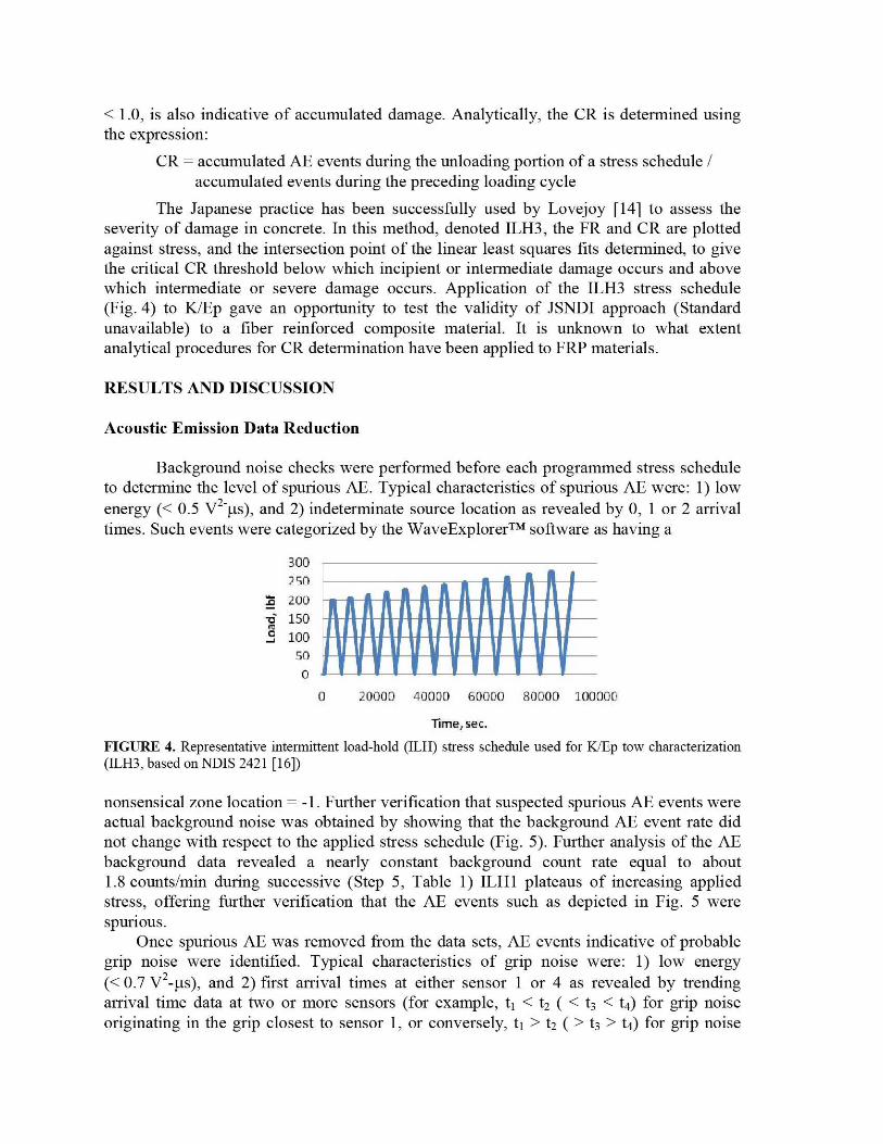
The Japanese practice has been successfully used by Lovejoy [14] to assess theseverity of damage in concrete. In this method, denoted ILH3, the FR and CR are plottedagainst stress, and the intersection point of the linear least squares fits determined, to givethe critical CR threshold below which incipient or intermediate damage occurs and abovewhich intermediate or severe damage occurs. Application of the ILH3 stress schedule(Fig. 4) to K/Ep gave an opportunity to test the validity of JSNDI approach (Standardunavailable) to a fiber reinforced composite material. It is unknown to what extentanalytical procedures for CR determination have been applied to FRP materials.
RESULTS AND DISCUSSION
Acoustic Emission Data Reduction
Background noise checks were performed before each programmed stress scheduleto determine the level of spurious AE. Typical characteristics of spurious AE were: 1) lowenergy (< 0.5 V2-^Ls), and 2) indeterminate source location as revealed by 0, 1 or 2 arrivaltimes. Such events were categorized by the WaveExplorerTM software as having a
Time, sec.
FIGURE 4. Representative intermittent load-hold (ILH) stress schedule used for K/Ep tow characterization(ILH3, based on NDIS 2421 [16])
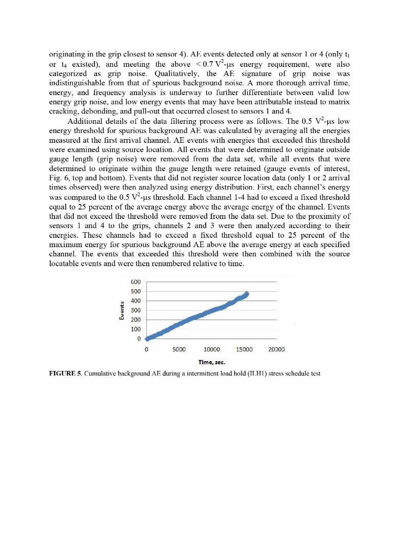
nonsensical zone location = -1. Further verification that suspected spurious AE events wereactual background noise was obtained by showing that the background AE event rate didnot change with respect to the applied stress schedule (Fig. 5). Further analysis of the AEbackground data revealed a nearly constant background count rate equal to about1.8 counts/min during successive (Step 5, Table 1) ILH1 plateaus of increasing appliedstress, offering further verification that the AE events such as depicted in Fig. 5 werespurious.
Once spurious AE was removed from the data sets, AE events indicative of probablegrip noise were identified. Typical characteristics of grip noise were: 1) low energy(< 0.7 V2_ µs), and 2) first arrival times at either sensor 1 or 4 as revealed by trendingarrival time data at two or more sensors (for example, t i < tz ( < t3 < t4) for grip noiseoriginating in the grip closest to sensor 1, or conversely, t i > t2 ( > t3 > t4) for grip noise
0 5000 10000 15000 20000
600500400
Ym 300
- 200100
0
originating in the grip closest to sensor 4). AE events detected only at sensor 1 or 4 (only tior t4 existed), and meeting the above < 0.7 V 2-µs energy requirement, were alsocategorized as grip noise. Qualitatively, the AE signature of grip noise wasindistinguishable from that of spurious background noise. A more thorough arrival time,energy, and frequency analysis is underway to further differentiate between valid lowenergy grip noise, and low energy events that may have been attributable instead to matrixcracking, debonding, and pull-out that occurred closest to sensors 1 and 4.
Additional details of the data filtering process were as follows. The 0.5 V 2-µs lowenergy threshold for spurious background AE was calculated by averaging all the energiesmeasured at the first arrival channel. AE events with energies that exceeded this thresholdwere examined using source location. All events that were determined to originate outsidegauge length (grip noise) were removed from the data set, while all events that weredetermined to originate within the gauge length were retained (gauge events of interest,Fig. 6, top and bottom). Events that did not register source location data (only 1 or 2 arrivaltimes observed) were then analyzed using energy distribution. First, each channel's energywas compared to the 0.5 V'-µs threshold. Each channel 1-4 had to exceed a fixed thresholdequal to 25 percent of the average energy above the average energy of the channel. Eventsthat did not exceed the threshold were removed from the data set. Due to the proximity ofsensors 1 and 4 to the grips, channels 2 and 3 were then analyzed according to theirenergies. These channels had to exceed a fixed threshold equal to 25 percent of themaximum energy for spurious background AE above the average energy at each specifiedchannel. The events that exceeded this threshold were then combined with the sourcelocatable events and were then renumbered relative to time.
Time, sec.
FIGURE 5. Cumulative background AE during a intermittent load hold (ILH1) stress schedule test

:. .... ......................................... .......
FIGURE 6. Significant AE events occurring in the gauge region at stresses where significant AE was firstobserved (top, t = 11,270 s), and a more energetic event close to one of the grips at a later time (bottom,t = 13,984 s), for a K/Ep tensile specimen subjected to an intermittent load hold (ILH2) stress schedule
Acoustic Emission Data Interpretation
Significant, source-locatable AE that exceeded the energy threshold screeningcriteria and also originated in the gauge region of the specimen (Fig. 6) were found to occurat loads above 890 N (200 lb f), which corresponds to an elapsed time greater than 11,000 sin the ILH2 method (Fig. 3). Another feature observed was a dramatic increase in the AEcount rate as failure was approached (Fig. 3). Nonlinear increases in the AE event rate aredescribed in ASTM E 1067 and E 1118 as corresponding to regions of critically intense AEactivity indicative of accumulated, severe damage. Also of note is the fact that theseregions also show the greatest violation of the Kaiser effect and, therefore, the lowest FRvalues. Similarly, the highest CRs should be observed in such regions.
Strain data are also known to correlate with AE data and give a fair indication of theproximity of failure. In fact, studies have shown that the strain rate in creep tests reaches aminimum about tNvo-thirds the way to failure in specimens held at constant stress [ 16].Other investigators have shown that outbursts of AE activity often coincide withdiscontinuous changes in strain [ 17]. However, for purposes of this investigation, it wassufficient to show that the ultimate strain was in agreement with published values. Forexample, an ultimate percent strain of about 3.5 percent was observed in the ILH2 stressschedule test, which compared favorably to the expected TRI value of 3.1 ± 0.2 percent.
Y = -0.0033x + 1.782R' = 0.9048
Felicity Ratio
Linear (Felicity Ratio)
1.4
1.20
1ro
T
LL0.4
0.2
0
The slightly higher ultimate percent strain may be due to specimen age since last tested(tested at TRI in 2006), or the ILH stress schedule used here versus the tensile test used byTRI.
Felicity Ratio Interpretation
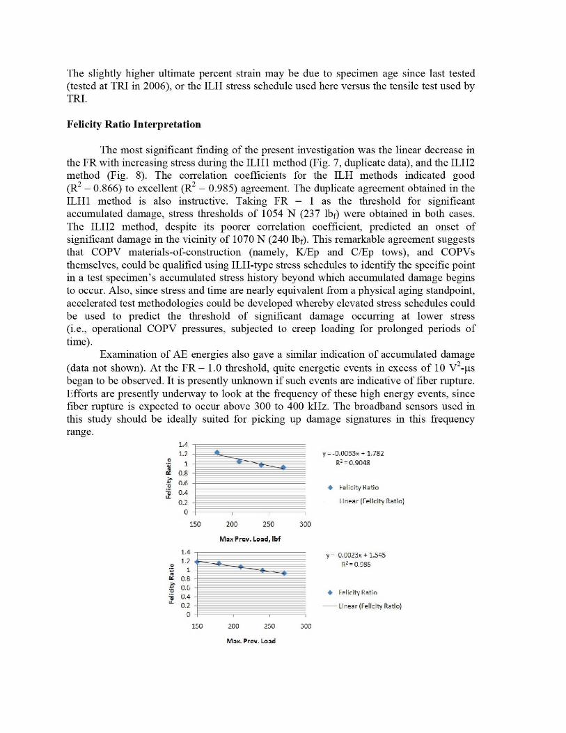
The most significant finding of the present investigation was the linear decrease inthe FR with increasing stress during the ILH1 method (Fig. 7, duplicate data), and the ILH2method (Fig. 8). The correlation coefficients for the ILH methods indicated good(R2 = 0.866) to excellent (R2 = 0.985) agreement. The duplicate agreement obtained in theILH1 method is also instructive. Taking FR = 1 as the threshold for significantaccumulated damage, stress thresholds of 1054 N (237 lb f) were obtained in both cases.The ILH2 method, despite its poorer correlation coefficient, predicted an onset ofsignificant damage in the vicinity of 1070 N (240 lb f). This remarkable agreement suggeststhat COPV materials-of-constriction (namely, K/Ep and C/Ep tows), and COPVsthemselves, could be qualified using ILH-type stress schedules to identify the specific pointin a test specimen's accumulated stress history beyond which accumulated damage beginsto occur. Also, since stress and time are nearly equivalent from a physical aging standpoint,accelerated test methodologies could be developed whereby elevated stress schedules couldbe used to predict the threshold of significant damage occurring at lower stress(i.e., operational COPV pressures, subjected to creep loading for prolonged periods oftime).
Examination of AE energies also gave a similar indication of accumulated damage(data not shown). At the FR = 1.0 threshold, quite energetic events in excess of 10 V2 -^Ls
began to be observed. It is presently unknown if such events are indicative of fiber rupture.Efforts are presently underway to look at the frequency of these high energy events, sincefiber rupture is expected to occur above 300 to 400 kHz. The broadband sensors used inthis study should be ideally suited for picking up damage signatures in this frequencyrange.
150 200 250 300
Max Prev. Load, lbf
1.4
0 1.2- 1
0-80.6
V 0.4LL 02
0150 200 250 300
Max. Prev. Load
y = -0.0023x + 1.545R , = 0.985
Felicity Ratio
—Linear (Felicity Ratio)

FIGURE 7. Dependence of Felicity ratio on stress during an intermittent load hold (ILH1) stress scheduletest (duplicate results).
Z.azo i.ai y = .0.000x + 1.1y8^ 1 R^ = a.865
0.99•^ — ^ Felicity RatioLL 0.98
- Linear (Felicity Ratio)0.97
220 240 260 280
Max Prev. Load, IV
FIGURE S. Dependence of Felicity ratio on stress during an intermittent load hold (IL112) stress scheduletest.
Calm Ratio Interpretation
CRs were not observed during the ILH1, or strangely enough, during the ILH3stress schedules. However, in the ILH2 case (data not shown), there was enough AEactivity during unloading portions of the test to obtain a measurable CR, so that a linearleast squares fit to the data could be made, and the intersection point of the linear leastsquares CR and FR fits determined, to give the critical CR threshold, below which incipientor intermediate damage occurred and above which intermediate or severe damage occurred.Development of optimized stress schedules may allow greater exploitation of CR data andallow quantitative thresholds for incipient, moderate, and severe damage to be determinedfor composite materials such as K/Ep and C/Ep.
SUMMARY
The Felicity ratio was found to give a reproducible estimate of the stress thresholdat which significant accumulated damage began to occur. Further refinement of stressschedules for determining Felicity ratio and Calm ratio could lead to robust pass-failacceptance criteria once the type, level, and significance of the accumulated damage isbetter understood. This, in turn, will entail fiirther reduction of the available or future AEdata sets to determine what precursor events are operative and when, and how much of agiven precursor event can be tolerated. That said, one observation stands out clearly:violation of the Kaiser effect (FR < 1.0) is paramount in assessing K/Ep damage and,therefore, in assessing damage in K/Ep overwraps. Future work is planned to ascertain theactual types of microscopic damage occurring at and below the FR = 1.0 threshold, as wellas the efficacy of using the intermittent load hold stress schedule approach towarddetermining damage thresholds in C/Ep.
ACKNOWLEDGMENTS
The authors are grateful to Shawn Arnette of TRI (Austin, TX) for supplying K/Eptest specimens, and to Paul Spencer and Ben Gonzalez (NASA White Sands Test Facility)for assistance with setting up the universal tensile tester. Ongoing efforts at WSTF to
develop AE methods specific to K/Ep and C/Ep have been sponsored by the Office ofSafety and Mission Assurance Office, NASA, Washington, DC.
REFERENCES
1. AIAA 5-081A-2006, Space Systems — Composite Overwrapped Pressure Vessels(COPVs), American Institute of Aeronautics and Astronautics, Reston, VA (2006).
2. J. Awerbuch and S. Ghafari, "Monitoring Progression of Matrix Splitting DuringFatigue Loading Through Acoustic Emission in Notched UnidirectionalGraphite/Epoxy Composites," J. Reinforced Plastics and Composites, 7, pp. 245-263(1988).
3. T. Ely and E. Hill, "Longitudinal Splitting and Fiber Breakage Characterization inGraphite Epoxy Using Acoustic Emission Data," :Mlatl. Eval., 288-294 (1995).
4. P. De Groot, P. Wijnen, and R. Janssen, "Real-time Frequency Determination ofAcoustic Emission for Different Fracture Mechanisms in Carbon/Epoxy Composites,"Composites Sci. Technol., 55, pp. 405-421 (1995).
5. W. H. Prosser, K. E. , Jackson, S. Kellas, B. T. Smith, J. McKeon, and A. Friedman,"Advanced, Waveform Based Acoustic Emission Detection of Matrix Cracking inComposites," Alatls. Eval., 53:9, pp. 1052-1058 (1995).
6. M. Shiwa, S. Carpenter, and T. Kishi, "Analysis of Acoustic Emission SignalsGenerated during the Fatigue Testing of GFRP," J. Composite IMlads., 30:18,pp. 2019-2041 (1996).
7. El Gueflounia, J.-C. Baboux, D. Ducret, N. Godin, P. Guy, S. Huguet, Y. Jayet, andT. Monnier, "Non-Destructive Evaluation of Damage and Failure of Fibre ReinforcedPolymer Composites Using Ultrasonic Waves and Acoustic Emission," Adv. Eng.lYlatl., 3:8, pp. 601-608 (2001).
8. S. Huguet, N. Godin, R. Gaertner, L. Salmon, and D. Villard, "Use of AcousticEmission to Identify Damage Modes in Glass Fibre Reinforced Polyester," CompositesSci Technol., 62, pp. 1433-1444 (2002).
9. Y. A. Dzenzis and J. Qlan, "Analysis of Microdamage Evolution Histories inComposites," Int. J. Solids and Structures, 38, pp. 1831-1854 (2001).
10. ASTM E 1118, Standard Practice for Acoustic Emission Examination of ReinforcedThermosetting Resin Pipe (RTRP), American Society for Testing and Materials, WestConshohocken, PA (2005).
11. ASTM E 976, Gitide for Determining the Reproducibility ofAcoustic Emission SensorResponse, American Society for Testing and Materials, West Conshohocken, PA(2005).
12. ASTM D 2343, Test Method for Tensile Properties of Glass Fiber Strands, Yarns, andRovings Used in Reinforced Plastics, American Society for Testing and Materials,West Conshohocken, Pennsylvania (2008).
13. ASTM E 1067, Standard Practice for Acoustic Emission Examination of FiberglassReinforced Plastic Resin (FRP) Tanks/Vessels, American Society for Testing and Materials,West Conshohocken, PA (2007).
14. S. Lovejoy, "A General Overview of Acoustic Emission Testing and it's Applicationsto Highway Infrastnicture," Northwest Transportation Conference, Oregon Departmentof Transportation (2008).
15. NDIS 2421, Recommended Practice for In Situ Monitoring of Concrete Structures byAcoustic Emission, Japanese Society for Non-Destructive Inspection (2000).
16. D. Sornette, "Statistical Physics of Rupture in Heterogeneous Media," J. JVech. Phys.Solids, (http://arXiv.ora/abs/condmat/0409524 (accessed June 30, 2009) (2005).
17. J. Waller and R. Saulsberry, "In-Situ NDE Characterization of Kevlar and CarbonComposite Micromechanics for Improved COPV Health Monitoring," NASA NDEWorking Group website, http://nnw .org/current/ (accessed June 30, 2009), underWhite Sands Test Facility (2008).