use of ipsec in mobile ip
TRANSCRIPT

Department of Electrical and Computer Engineering
ELEG 777 Internet Engineering
( TERM PAPER )
Use of IPSec in Mobile IP
DONE BY: SALEM ITANI ID #: 20011003 SUBMITTED TO: Dr. AYMAN KAYSSI DATE: MAY 21, 2001

1
INTRODUCTION As mobile computing has become a reality, new technologies and protocols have been developed to provide to mobile users the services that already exist for non-mobile users. Mobile IP, one of these technologies, enables a node to change its point of attachment to an internet in a manner transparent to applications running on top of the protocol stack, since its IP address does not change. To provide this transparency, new elements are required: the “home agent”(HA), located in the home network, will forward all incoming packets addressed to the mobile node’s (MN) new location. The foreign agent (FA) is responsible for providing a temporary address to the MN. The flexibility of communication through the Internet allows the existence of such protocols as Mobile IP. As much as this is true, it is as well the fact that every time new protocols or services are made available on the Internet, new security challenges arise. IPSec has been developed as a protocol to provide security at the IP layer. That is to say, using IPSec all communications on the Internet can be accomplished in a secure fashion. Providing security is not an easy task, since many situations have to be taken into account. The approach IPSec uses to address security is by managing two key concepts: privacy and authentication. In this paper, the MOBILE IPv4 & MOBILE IPv6 with the security considerations are introduced, after that the IPsec is explained, focusing on the IP Authentication Header and the IPsec Encapsulating Security Payload. Then the USE OF IPsec IN MOBILE IP part is treated, finally a performance analysis done in Carnegie Mellon University on IPsec usage in MOBILE IP on wireless environments is presented.
MOBILE IPV4 The current Mobile IPv4 protocol is completely transparent to the transport and higher layers and does not require any changes to existing Internet hosts and routers. The Mobile IP protocol allows the MNs to retain their IP address regardless of their point of attachment to the network. This can be fulfilled by allowing the MN to use two IP addresses. The first one, called home address, is static and is mainly used to identify higher layer connections, e.g., TCP. The second IP address that can be used by a MN is the Care-of Address. While the mobile is roaming among different networks, the Care-of Address changes. The reason of this is that the Care-of Address has to identify the mobile’s new point of attachment with respect to the network topology. In Mobile IPv4 the Care-of Address management is achieved by an entity called Foreign Agent. The Mobile Node, using its home address is appearing to be able to receive data on its home network, through a Home Agent. In the situation that the mobile roams into a foreign region, it will need to obtain, a new Care-of Address via the Foreign Agent. Note that, in this situation the Mobile Node can also obtain a new Care-of Address by contacting the Dynamic Host Configuration Protocol (DHCP) [RFC1541] or Point-to-Point Protocol (PPP) [RFC1661]. This new Care-of Address will be registered with its Home Agent.

2
The Correspondent Host (CH) starts a connection and at the moment that the Home Agent receives a packet that has to be send to the mobile, it delivers it from the home network to the mobile’s Care-of Address. The delivery can take place only if the packet is redirected or tunneled, such that the Care-of Address appears as the destination IP address. The Home Agent tunnels the packet to the Foreign Agent. After receiving the packet, the Foreign Agent will have to apply the reverse transformation to decapsulate it, such that the packet will appear to have the mobile’s home address as the destination IP address. After decapsulation, the packet is sent to the Mobile Node. Due to the fact that the packet arrives at the Mobile Node, being addressed to its home address, it will be processed properly by the upper protocol layers, e.g., TCP. The IP packets sent by the Mobile Node, are delivered by standard IP routing procedures, each to its destination. When the Mobile IP packet flow, follows a route similar to the one viewed in Figure, then the routing situation is typically called triangle routing, since the packet sent by the correspondent host follows the path 1,2 and 3, while the packet sent by the Mobile Node will follow routes 3 and 4. Prot 4 or55 Src Dest Discovering the Care-of Address The Care-of address discovery procedure used in Mobile IP is based on the ICMP Router Advertisement standard protocol, specified in RFC 1256 [RFC1256]. In Mobile IPv4, the router advertisements are extended to also contain the required Care-of Address. These extended router advertisements are known as agent advertisements. Agent advertisements are typically broadcasted at regular intervals (e.g., once a second, or once every few seconds) and in a random fashion, by Home Agents and Foreign Agents. However, if a mobile needs to get a Care-of Address instantaneously, the Mobile Node can broadcast or multicast a solicitation that will be answered by any Foreign Agent or Home Agent that receives it. The functions performed by an agent advertisement are the following: - Allows the detection of Home Agents and Foreign Agents; - Lists one (or more available) care-of addresses; - Informs the Mobile Node about special features provided by Foreign Agents, e.g., alternative encapsulation techniques; - Permits Mobile Nodes to determine the network number and congestion status of their link to the Internet; - Lets the Mobile Node know, whether it is in its home network or in a foreign network by identifying whether the agent is a Home Agent, a Foreign Agent, or both.
CH 1
CHA MNHA
HA FA 2
4
3 MN
MNHA CHA
CHA MNHA HAA COA CHA MNHA

3
In Mobile IP, the changes in the set of available mobility agents are detected by using ICMP router solicitations (agent solicitation) procedures defined in [RFC1256]. If the Mobile Node does not anymore receive agent solicitation advertisements from a Foreign Agent, it will presume that this Foreign Agent is not anymore within the range of its network interface. Registering the Care-of Address After the Mobile Node gets the Care-of Address it will have to inform the Home Agent about it. The Mobile Node sends a registration request (using the User Datagram Protocol (UDP)) with the Care-of Address information. This information is received by the Home Agent and normally, if the request is approved it adds the necessary information to its routing table and sends a registration reply back to the Mobile Node through the foreign agent. The flags and parameters required to characterise the tunnel, through which the Home Agent will deliver packets to the Care-of Address, are contained in the registration request message. After accepting a registration request, the Home Agent begins to associate the home address of the Mobile Node with the Care-of Address for a pre-specified time duration, called registration lifetime. The group that contains the home address, Care-of Address, and registration lifetime is called a binding for the Mobile Node. This binding is updated by the Mobile Node at regular intervals, sending a registration request to the Home Agent. During the registration procedure, there is a need to authenticate the registration information. The reason is that a malicious node could cause the Home Agent to alter its routing table with erroneous Care-of Address information, and then the Mobile Node would be unreachable. Therefore, each Mobile Node and Home Agent must share a security association. Tunnelling to the Care-of Address The tunnelling to the Care-of Address is accomplished by using encapsulation mechanisms. All mobility agents, i.e., Home Agents and Foreign Agents, using Mobile IPv4 must be able to use a default encapsulation mechanism included in the IP within IP protocol [RFC2003]. By using this protocol, the source of the tunnel, i.e., Home Agent, inserts an IP tunnel header, in front of the header of any original IP packet addressed to
MN FA
HA
MN requests service FA relays request to MN
FA relays status to MN HA accepts or denies
4
the Mobile Node’s home address. The destination of this tunnel is the Mobile Node’s Care-of Address. In IP within IP [RFC2003] there is a way to indicate that the next protocol header is again an IP header. This is accomplished by indicating in the tunnel header that the higher level protocol number is ‘4’. The entire original IP header is preserved as the first part of the payload of the packet. By eliminating the tunnel header the original packet can be recovered. Proxy and gratuitous Address Resolution Protocol (ARP) The IP nodes located in the home network of a Mobile Node are able to communicate with the Mobile Node while it is at home, by using ARP [RFC826] cache entries for this Mobile Node. When the Mobile Node moves to another subnetwork, the Home Agent will have to inform all IP nodes in the home network that the Mobile Node moved away. This is accomplished, by sending gratuitous ARP messages. These messages will update all ARP caches of each node in the home network. After that moment the packets sent by these IP nodes, to the Mobile Node will be intercepted by the Home Agent by using proxy ARP. The intercepted packets are then tunnelled to the care of address. Route Optimisation in Mobile IP The operation of the base Mobile IP protocol is extended to allow for more efficient routing procedures, such that IP packets can be routed from a correspondent host to a Mobile Node without going to the Home Agent first. These extensions are referred to as route optimisation, where in new methods for IP nodes, e.g., correspondent hosts, are provided. The correspondent host receives a binding1 update message from the mobile’s node Home Agent, that contains the Mobile Node’s Care-of Address. This binding is then stored by the correspondent host and is used to tunnel its own IP packets directly to the care-of address indicated in that binding, bypassing the Mobile Node's Home Agent. In this way, the triangular routing situation, explained previously is eliminated. However, in the initiation phase, the IP packets sent by the correspondent host still use the triangle routing until the moment that the binding update message sent by the Mobile Node’s Home Agent, is received by the correspondent host. Extensions are also provided, to allow IP packets sent by a correspondent host with an out-of-date stored binding, or in transit, to be forwarded directly to the Mobile Node's new care-of address. All operation of route optimisation that changes the routing of IP packets to the Mobile Node is authenticated using the same type of mechanisms also used in the base Mobile IP protocol. This authentication generally relies on a mobility security association established in advance between the sender and receiver of such messages. The route optimisation protocol operates four steps: - A binding warning control message is usually sent by a node (e.g., Mobile Node or Correspondent Host), to the Home Agent (i.e., recipient), indicating that a 1 Binding: The association of the home address of a Mobile Node with a care-of address for that Mobile Node, along with the remaining lifetime of that association.

5
Correspondent Host (i.e., target) seems unaware of the Mobile Node’s new Care-of Address; - A binding request message is sent by a Correspondent Host to the Home Agent at the moment it determines that its binding should be refreshed; -Typically an authenticated binding update message is sent by the Home Agent to all the Correspondent Hosts that need them, containing the Mobile Node’s current Care-of Address; -A binding acknowledgement message can be requested by a Mobile Node from a Correspondent Host that has had received the binding update message. Security issues The security open issues that are related to Mobile IPv4 are listed below: Ingress filtering: In an ISP any border router, may discard packets that contain a source IP address, that is not being configured for one of the ISP’s internal network. This issue is called ingress filtering. In Mobile IPv4 the Mobile Nodes that are away from home, i.e., in a foreign ISP use their home address as the source IP address, that is different than the IP addresses configured in the ISP’s internal network. Minimise the number of required trusted entities: Security may be enhanced, if the number of the required trusted entities, i.e., Home Agent, Foreign Agent, in a Mobile IP scenario is decreased. Authentication: The recipient of a message should be able to determine who the actual (real) originator of the message is. Therefore authentication procedures between mobile agents and Mobile Nodes should be provided. The Mobile IPv4 authentication techniques between Mobile Nodes and Foreign Agents are not reliable enough. Authorisation: An organisation that owns or operates a network would need to decide who may attach to this network and what network resources may be used by the attaching node. Non-repudiation: In the future wireless Internet, a recipient of a message should have the opportunity, to prove that a message has been originated by a sender. In other words, the sender of a message should not be able to falsely deny that it originated a message at a later time. Encryption key distribution: The authentication, integrity and non-repudiation can only be accurately provided (inforced) by using some form of cryptography which requires the distribution/exchange of encryption key information amongst message senders and receivers. In other words key management procedures should be supported by Mobile IP. Two methods can be used for this purpose. One method for distributing the key information is to manually load it into each node. For a small number of nodes this is possible but it runs into administrative problems. Another method to distribute the key information is dynamical, using basic IETF security protocols. Location privacy: A sender of a message should able to control which, if any, receivers know the location of the sender’s current physical attachment to the network. Location privacy is concerned with hiding the location of a Mobile Node from Correspondent Hosts.

6
Use one single subscription for all service types: In RFC 2468 [RFC2468] the Network Access Identifier (NAI) is defined, it is used to identify ISP subscribers during roaming operations. Regarding second and third generation cellular networks, an interesting approach for cellular service providers would be to evolve their home cellular networks to provide second and third generation cellular services, IP packet data services and so on with a single subscription using NAIs. Mobile IPv4 does not provide solutions to this issue. Firewall support in Mobile IP: If a Mobile Node has to enter a private Internet network (Intranet) that is securely protected by a firewall, then Mobile IP aware support at this firewall is required. In Mobile IP this support is not provided.
MOBILE IPV6 Comparison with Mobile IPv4 Mobile IPv6 shares many features with Mobile IPv4, but the protocol provides many improvements over Mobile IPv4. The major differences between Mobile IPv4 and Mobile IPv6 are: - Support for "Route Optimisation". This feature is now built in as a fundamental part of the Mobile IPv6 protocol. In Mobile Ipv4 the route optimisation feature is being added on as an optional set of extensions that may not be supported by all IP nodes. - In Mobile IPv6 (also integrated in the IPv6) a new feature is specified that allows Mobile Nodes and Mobile IP to coexist efficiently with routers that perform "ingress filtering" .The packets sent by a Mobile Node can pass normally through ingress filtering routers. This can be accomplished due to the fact that the care-of address is used as the Source Address in each packet’s IP header. Moreover, the Mobile Node’s home address is carried in the packet in a Home Address destination option. This allows the use of the care-of address in the packet to be transparent above the IP layer, e.g., TCP. - By using the care-of address as the Source Address in each packet's IP header the routing of multicast packets sent by a Mobile Node is simplified. In Mobile IPv6 the Mobile Node will not anymore have to tunnel multicast packets, as in Mobile IPv4, to its Home Agent Moreover, the use of the Home Address option allows the home address to be used but still be compatible with multicast routing that is based in part, on the packet's Source Address. -In Mobile IPv6 the functionality of the Foreign Agents can be accomplished by IPv6 enhanced features, such as Neighbour Discovery, [RFC1970] and Address Autoconfiguration, [RFC1971]. Therefore, there is no need to deploy Foreign Agents in Mobile IPv6. -The Mobile IPv6, unlike Mobile IPv4, uses IPsec for all security requirements such as sender authentication, data integrity protection, and replay protection for Binding Updates (which serve the role of both registration and Route Optimisation in Mobile

7
IPv4). In Mobile IPv4 the security requirements are provided by its own security mechanisms for each function, based on statically configured mobility security associations. - In mobile IPv6 a mechanism is provided to support bidirectional (i.e., packets that the router sends are reaching the Mobile Node, and packets that the Mobile Node sends are reaching the router) confirmation of a Mobile Node's ability to communicate with its default router in its current location. This bidirectional confirmation can be used to detect the “black hole” situation, where the link to the router does not work equally well in both directions. In contrast, Mobile IPv4 does not support bidirectional confirmation, but only the forward direction (packets from the router are reaching the Mobile Node) is confirmed, and therefore the black hole situation may not be detected. - Mobile IPv6 and IPv6 use the source routing feature. This feature makes it possible for a Correspondent Host to send packets to a Mobile Node while it is away from its home network using an IPv6 Routing header rather than IP encapsulation, whereas Mobile IPv4 must use encapsulation for all packets. However, in Mobile IPv6 the Home Agents are allowed to use encapsulation for tunnelling. This is required, during the initiation phase of the binding update procedure. -In Mobile IPv6 the packets which arrive at the home network and are destined for a Mobile Node that is away from home, are intercepted by the Mobile Node’s Home Agent using IPv6 Neighbour Discovery,[RFC1970] rather than ARP [RFC826] as is used in Mobile IPv4. - The source routing (routing header) feature in Mobile IPv6 removes the need to manage "tunnel soft state", which was required in Mobile IPv4 due to limitations in ICMP error procedure for IPv4. In Mobile IPv4 an ICMP error message that is created due to a failure of delivering an IP packet to the Care-of Address, will be returned to the home network, but will may not contain the IP address of the original source of the tunnelled IP packet. This is solved in the Home Agent by storing the tunnelling information, i.e., which IP packets have been tunnelled to which Care-of Address, called tunnelling soft state. - In IPv6 a new routing procedure is defined called anycast. This feature is used in Mobile IPv6 for the dynamic Home Agent address discovery mechanism. This mechanism returns one single reply to the Mobile Node, rather than the corresponding Mobile IPv4 mechanism that used IPv4 directed broadcast and returned a separate reply from each Home Agent on the Mobile Node's home subnetwork. The Mobile IPv6 mechanism is more efficient and more reliable. This is due to the fact that only one packet need to be replied to the Mobile Node. - In Mobile IPv6 an Advertisement Interval option on Router Advertisements (equivalent to Agent Advertisements in Mobile IPv4) is defined, that allows a Mobile Node to decide for itself how many Router Advertisements (Agent Advertisements) it is tolerating to miss before declaring its current router unreachable. - All Mobile Ipv6 control traffic can be piggybacked on any existing IPv6 packets. This can be accomplished by using the IPv6 destination options. In contrary, for Mobile IPv4 and its Route Optimisation extensions, separate UDP packets were required for each control message.

8
Security Considerations
Binding Updates, Acknowledgements, and Requests The Binding Update option will result in packets addressed to a mobile node being delivered instead to its care-of address. This ability to change the routing of these packets could be a significant vulnerability if any packet containing a Binding Update option was not authenticated. Such use of "remote redirection", for instance as performed by the Binding Update option, is widely understood to be a security problem in the current Internet if not authenticated. The Binding Acknowledgement option also requires authentication, since, for example, an attacker could otherwise trick a mobile node into believing a different outcome from a registration attempt with its home agent. No authentication is required for the Binding Request option, since the use of this option does not modify or create any state in either the sender or the receiver. The Binding Request option does open some issues with binding privacy, but those issues can be dealt with either through existing IPsec encryption mechanisms or through use of firewalls. The existing IPsec replay protection mechanisms allow a "replay protection window" to support receiving packets out of order. Although appropriate for many forms of communication, Binding Updates must be applied only in the order sent. The Binding Update option thus includes a Sequence Number field to provide this necessary sequencing. The use of this Sequence Number together with Ipsec replay protection is similar in many ways, for example, to the sequence number in TCP. IPsec provides strong replay protection but no ordering, and the sequence number provides ordering but need not worry about replay protection such as through the sequence number wrapping around. Home Address Option No special authentication of the Home Address option is required, except that if the IPv6 header of a packet is covered by authentication, then that authentication must also cover the Home Address option; this coverage is achieved automatically by the definition of the Option Type code for the Home Address option since it indicates that the option is included in the authentication computation. Thus, even when authentication is used in the IPv6 header, the security of the Source Address field in the IPv6 header is not compromised by the presence of a Home Address option. Without authentication of the packet, then any field in the IPv6 header, including the Source Address field, and any other parts of the packet, including the Home Address option, can be forged or modified in transit. In this case, the contents of the Home Address option is no more suspect than any other part of the packet. The use of the Home Address option allows packets sent by a mobile node to pass normally through routers implementing ingress filtering. Since the care-of address used
9
in the Source Address field of the packet's IPv6 header is topologically correct for the sending location of the mobile node, ingress filtering can trace the location of the mobile node in the same way as can be done with any sender when ingress filtering is in use. However, if a node receiving a packet that includes a Home Address option implements the processing of this option by physically copying the Home Address field from the option into the IPv6 header, replacing the Source Address field there, then the ability to trace the true location of the sender is removed once this step in the processing is performed. This diminishing of the power of ingress filtering only occurs once the packet has been received at its ultimate destination, and does not affect the capability of ingress filtering while the packet is in transit. Furthermore, this diminishing can be entirely eliminated by appropriate implementation techniques in the receiving node. For example, the original contents of the Source Address field (the sending care-of address) could be saved elsewhere in memory with the packet, until all processing of the packet is completed.
IPsec
Introduction The IPsec protocol suite is used to provide privacy and authentication services at the IP layer. It provides a set of security algorithms plus a general framework that allows a pair of communicating entities to use whichever algorithms provide security appropriate for the communication. The elements describing the set of IPsec protocols are divided into seven groups: There is the main Architecture, which broadly contain the general concepts, security requirements, definitions, and mechanisms defining IPsec technology. There is the ESP Protocol and an AH Protocol which contain the packet format and general issues regarding the respective protocols. The "Encryption Algorithm", describes how various encryption algorithms are used for ESP. The "Authentication Algorithm", describes how various authentication algorithms are used for both ESP and AH. The "Key Management ". The DOI contains values needed for the other elements to relate to each other. This includes for example encryption algorithms, authentication algorithms, and operational parameters such as key lifetimes.

10
In this part we will focus on the IP Authentication Header and the IPSec Encapsulating Security Payload as shown below. The IP Authentication Header
The IP Authentication Header (AH) is used to provide connectionless integrity and data origin authentication for IP datagrams, and to provide protection against replays. The protocol header (IPv4, IPv6, or Extension) immediately preceding the AH header will contain the value 51 in its Protocol (IPv4) or Next Header (IPv6, Extension) field.
0 8 16 31
Next Header: The Next Header is an 8-bit field that identifies the type of the next payload after the Authentication Header. Payload Length: This 8-bit field specifies the length of AH in 32-bit words (4-byte units), minus "2". AH is an IPv6 extension header. However, since its length is measured in 32-bit words, the "Payload Length" is calculated by subtracting 2 (32 bit words). In the "standard" case of a 96-bit authentication value plus the 3 32-bit word fixed portion, this length field will be "4". A "null" authentication algorithm may be used only for debugging purposes. Its use would result in a "1" value for this field forIPv4 or a "2" for IPv6, as there would be no corresponding Authentication Data field. Reserved: This 16-bit field is reserved for future use. It must be set to "zero." Security Parameters Index (SPI) The SPI is an arbitrary 32-bit value that, in combination with the destination IP address and security protocol (AH), uniquely identifies the Security Association for this datagram. The set of SPI values in the range 1 through 255 are reserved by the Internet Assigned Numbers Authority (IANA) for future use; a reserved SPI value will not normally be assigned by IANA unless the use of the assigned SPI value is specified in an RFC. It is ordinarily selected by the destination system. Sequence Number: This unsigned 32-bit field contains a monotonically increasing counter value (sequence number). It is obligatory and is always present even if the
NEXT HEADER PAYLOAD LEN
SEQUENCE NUMBER
RESERVED
SECURITY PARAMETERS INDEX
AUTHENTICATION DATA (VARIABLE)

11
receiver does not elect to enable the anti-replay service for a specific SA2, when Processing of the Sequence Number field is at the discretion of the receiver, i.e., the sender must always transmit this field, but the receiver need not act upon it. The sender's counter and the receiver's counter are initialized to 0 when an SA is established and the first packet sent using a given SA will have a Sequence Number of 1. If anti-replay is enabled, the transmitted Sequence Number must never be allowed to cycle. Thus, the sender's counter and the receiver's counter must be reset (by establishing a new SA and thus a new key) prior to the transmission of the 2^32nd packet on an SA. Authentication Data: This is a variable-length field that contains the Integrity Check Value (ICV) for this packet. The field must be an integral multiple of 32 bits in length. This field may include explicit padding. This padding is included to ensure that the length of the AH header is an integral multiple of 32 bits (IPv4) or 64 bits (IPv6). The authentication algorithm specification must specify the length of the ICV and the comparison rules and processing steps for validation.
Authentication Header Location
AH may be employed in two ways: transport mode or tunnel mode. The former mode is applicable only to host implementations and provides protection for upper layer protocols, in addition to selected IP header fields. In transport mode, AH is inserted after the IP header and before an upper layer protocol, e.g., TCP, UDP, ICMP, etc. or before any other IPsec headers that have already been inserted. The following diagram illustrates AH transport mode positioning for a typical IPv4 packet, on a "before and after" basis.
BEFORE APPLYING AH
IPv4
AFTER APPLYING AH
IPv4
|<--------------- authenticated -----------? |
In the IPv6 context, AH is viewed as an end-to-end payload, and thus should appear after hop-by-hop, routing, and fragmentation extension headers. The destination options extension header(s) could appear either before or after the AH header depending on the
2 To save space in the header, IPsec arranges for each receiver to collect all the details about a security scheme into an abstraction known as security association “SA”. Each SA is given a number, known as SECURITY PARAMETER INDEX, through which it is identified.
|orig IP hdr |AH |TCP | DATA |
|orig IP hdr | TCP| DATA |

12
semantics desired. The following diagram illustrates AH transport mode positioning for a typical IPv6 packet.
BEFORE APPLYING AH IPv6
AFTER APPLYING AH IPv6
| <------------------------- authenticated except for mutable fields ------------------------>|
Tunnel mode AH may be employed in either hosts or security gateways. When AH is implemented in a security gateway (to protect transit traffic), tunnel mode must be used. In tunnel mode, the "inner" IP header carries the ultimate source and destination addresses, while an "outer" IP header may contain distinct IP addresses, e.g., addresses of security gateways. In tunnel mode, AH protects the entire inner IP packet, including the entire inner IP header. The position of AH in tunnel mode, relative to the outer IP header, is the same as for AH in transport mode. The following diagram illustrates AH tunnel mode positioning for typical IPv4 and IPv6 packets.
IPv4
|<-authenticated except for mutable fields in the new IP hdr ->|
IPv6
|?------------ authenticated except for mutable fields in new IP hdr ----------->|
| orig IP hdr | ext hdrs | | TCP| Data|
| orig IP hdr |hop-by-hop, dest, routing, fragment. | AH | dest | TCP | Data |
| new IP hdr | AH | orig IP hdr | TCP | Data |
| new IP hdr | ext hdrs| AH | orig IP hdr | ext hdrs| TCP | Data |

13
IPsec Encapsulating Security Payload The Encapsulating Security Payload (ESP) header is designed to provide a mix of security services in IPv4 and IPv6. ESP may be applied alone, in combination with the IP Authentication Header (AH), or in a nested fashion, e.g., through the use of tunnel mode. ESP is used to provide confidentiality, data origin authentication, connectionless integrity, an anti-replay service (a form of partial sequence integrity), and limited traffic flow confidentiality. The set of services provided depends on options selected at the time of Security Association establishment and on the placement of the implementation. Confidentiality may be selected independent of all other services. Data origin authentication and connectionless integrity are joint services (here after referred to jointly as authentication) and are offered as an option in conjunction with confidentiality. The anti-replay service may be selected only if data origin authentication is selected, and its election is solely at the discretion of the receiver. Traffic flow confidentiality requires selection of tunnel mode, and is most effective if implemented at a security gateway, where traffic aggregation may be able to mask true source-destination patterns. The ESP header is inserted after the IP header and before the upper layer protocol header (transport mode) or before an encapsulated IP header (tunnel mode). For IPv4 a value of 50 in the PROTOCOL field of the datagram informs a receiver that the datagram carries ESP. The following diagram illustrates ESP transport mode positioning for a typical IPv4 packet, on a "before and after" basis. Before: After: As the figure shows, ESP adds three additional areas to the datagram. The ESP HEADER immediately follows the IP header and precedes the encrypted payload. The ESP TRAILER is encrypted along with the payload; a variable size ESP AUTH field follows the encrypted section.
Ipv4 Header
TCP Header
TCP DATA
ESP Header
TCP Header
TCP DATA
ESP Header
ESP Trailer
ESP AUTH
IPv4 Header
authenticated
encrypted

14
In the IPv6 context, ESP is viewed as an end-to-end payload, and thus should appear after hop-by-hop, routing, and fragmentation extension headers. The destination options extension header(s) could appear either before or after the ESP header depending on the semantics desired. However, since ESP protects only fields after the ESP header, it generally may be desirable to place the destination options header(s) after the ESP header. The following diagram illustrates ESP transport mode positioning for a typical IPv6 packet. Before:
After:
Tunnel mode ESP may be employed in either hosts or security gateways. When ESP is implemented in a security gateway (to protect subscriber transit traffic), tunnel mode must be used. In tunnel mode, the "inner" IP header carries the ultimate source and destination addresses, while an "outer" IP header may contain distinct IP addresses, e.g., addresses of security gateways. In tunnel mode, ESP protects the entire inner IP packet, including the entire inner IP header. The position of ESP in tunnel mode, relative to the outer IP header, is the same as for ESP in transport mode. The following diagram illustrates ESP tunnel mode positioning for typical IPv4 and IPv6 packets. IPv4:
orig IP hdr ext hdrs if present
TCP Data
Orig IP hdr
hxh, rtg, frag if present
Dest opt
ESP hdr
Data ESP Trailer
ESP Auth
Dest opt
TCP
encrypted
authenticated
Data ESP Header
ESP
New Ip hdr
ESP Trailer
ESP AUTH
authenticated
encrypted
TCP Orig IP hdr Data

15
IPv6: Encapsulating Security Payload Packet Format The ESP HEADER consists of 8 octets that identify the security parameters index and a sequence number. 0 16 31 The ESP TRAILER consists of optional padding, a padding length field, PAD LENGTH, and a NEXT HEADER field that is followed by a variable amount of authentication data. Obviously, the payload data is located between the header and trailer. Security Parameters Index: The SPI is an arbitrary 32-bit value that uniquely identifies the Security Association for this datagram, relative to the destination IP address contained in the IP header (with which this security header is associated) and relative to the security protocol employed. The set of SPI values in the range 1 through 255 are reserved by the Internet Assigned Numbers Authority (IANA) for future use; a reserved SPI value will not normally be assigned by IANA unless the use of the assigned SPI value is specified in an RFC. It is ordinarily selected by the destination system upon establishment of an SA.(A zero value may be used within an ESP implementation for
New IP hdr
Ext hdrs ESP Orig. IP hdr
Data ESP Trailer
ESP Auth
Ext hdrs
TCP
encrypted
authenticated
SECURIY PARAMETERS INDEX
SEQUENCE NUMBER
0-255 OCTETS OF PADDING PAD LENGTH NEXT HEADER
ESP AUTHENTICATION DATA (VARIABLE) ……..

16
local debugging purposes, but no ESP packets should be transmitted with a zero SPI value). Sequence Number: This unsigned 32-bit field contains a monotonically increasing counter value (sequence number). The counter is initialized to 1 when an SA is established. The Sequence Number must never be allowed to cycle; thus, it must be reset by establishing a new SA and thus a new key prior to the transmission of 2^32-1 packets on an SA. The Sequence Number is obligatory. It is always included in an ESP packet, to ensure alignment of the Payload field on an 8-byte boundary (in support of IPv6). Even if authentication is not selected as a security service for the SA, or if ESP is employed in an IPv4 environment, this field must be present. Processing of the Sequence Number field is at the discretion of the receiver, i.e., the sender must always transmit this field, but the receiver need not act upon it . Payload Data : Payload Data is a variable-length field containing data described by the Next Header field. The Payload Data field is mandatory and is an integral number of bytes in length. If the algorithm used to encrypt the payload requires cryptographic synchronization data, then this data may be carried explicitly in the Payload field. Any encryption algorithm that requires such explicit, per-packet synchronization data must indicate the length and any structure for such data. Padding (for Encryption): If an encryption algorithm is employed that requires the plaintext to be a multiple of some number of bytes, e.g., the block size of a block cipher, the Padding field is used to fill the plaintext (consisting of the Payload Data, Pad Length and Next Header fields, as well as the Padding) to the size required by the algorithm. Any encryption algorithm used with ESP that requires padding must define its padding requirements in an RFC specifying how the algorithm is used with ESP. Padding also may be required, irrespective of algorithm requirements, to ensure that the resulting ciphertext terminates on a 4-byte boundary, i.e., the Pad Length and Next Header fields must be right aligned within a 4-byte word, as illustrated in the ESP packet format figure. Finally, padding beyond that required for the algorithm or alignment reasons cited above, may be used to conceal the actual length of the payload, in support of (partial) traffic flow confidentiality. However, inclusion of such additional padding has adverse bandwidth implications and thus its use should be undertaken with care. The Padding field is optional, but all implementations must support generation and consumption of padding. Pad Length: The Pad Length field indicates the number of pad bytes immediately preceding it. The range of valid values is 0-255, where a value of zero indicates that the byte immediately preceding the pad length field is the last byte of the payload. The Pad Length field is mandatory. Next Header :The Next Header is an 8-bit field that identifies the type of data contained in the Payload Data field, e.g., an extension header in IPv6 or an upper layer protocol

17
identifier. The value of this field is chosen from the set of IP Protocol Numbers defined in the most recent "Assigned Numbers" RFC from the Internet Assigned Numbers Authority (IANA). The Next Header field is obligatory. Authentication Data : The Authentication Data is a variable-length field containing an Integrity Check Value (ICV) computed over the ESP packet minus the Authentication Data. The length of the field depends upon the authentication function selected. The mandatory-to-implement authentication algorithms, HMAC with MD5 or SHA-1, both yield 96-bit ICV's because of the truncation convention adopted for use in IPsec. The Authentication Data field is optional, and is included only if the authentication service has been selected for the SA in question.
USE OF IPsec IN MOBILE IP
The use of IPSec ESP protocol in the Mobile IP packet redirection tunnels will protect the redirected packets against both passive and active attacks launched and aid these packets to traverse the firewalls surrounding both the home and the foreign subnets visited by the mobile nodes. Use of IPSec on Mobile IP Redirection Tunnels The IPSec protected Mobile IP tunnels (MIP_IPSec tunnels) offer message confidentiality and authentication (including data origin authentication and connectionless integrity) but not anti-replay services to the IP datagrams to and from the mobile nodes (MNs) passing through the mobility agents, i.e. home agents (HAs) and foreign agents (FAs). Selective use of these tunnels coupled with rule/identity based access control can provide the security services. The proposed scheme made certain assumptions on the architecture and implementation of this secure Mobile IP system. These assumptions are stated below: - In order to use the MIP-IPSec tunnels and the mobility agents for the best protection of the mobile Internet, both FAs and HAs should function as IPSec supporting security gateways capable of performing packet encryption/decryption and packet filtering based on strong authentication. - On a firewall protected foreign subnet, the FAs should be the firewalls closest to the mobile nodes (MNs). Other firewalls on the subnet should permit the IPSec protected packets to and from the FAs to pass through. Reverse tunneling must be used if INGRES source filtering is employed by the firewalls.

18
- The HAs should function as the innermost firewall guarding the home subnet. Similarly, other firewalls on the subnet should permit the IPSec protected packets to and from the HAs to pass through. - The IPSec implementation is expected to be integrated with the Mobile IP implementation. Such an approach allows the use of a single IP-IP encapsulation to be used for both IPSec protection and Mobile IP packet redirection (except when MN-HA IPSec tunnels are used). The approach is also consistent with the new roles of FAs and HAs as IPSec supporting security gateways. The MIP-IPSec tunnels running between MN-HA, HA-FA, FA-MN are the essential ones for fulfilling the security requirements. They will be examined individually in the following paragraphs. In addition, the end-to-end IPSec protection between MNs and CHs can be used in combination with the IPSec tunnels. Notice that Mobile IP tunnels do not run between CHs and HAs, and the tunnels running between CHs and FAs exist only in route-optimized Mobile IP. This is because corresponding hosts may be completely ignorant of Mobile IP, and may not know of the existence of FAs and HAs.
??MN-HA Tunnels The MN-HA MIP-IPSec tunnels can be used to provide data-origin authentication plus connectionless integrity and data confidentiality. They are most useful in providing a secure communication path between a MN and its home subnet as shown in the following diagram. (Internet) admin. boundary The data-origin authentication and connectionless integrity can counter active attack while data confidentiality can frustrate eavesdropping. By using the tunnels in both directions, a MN should be allowed to enjoy same connectivity as it has at home. The MN-HA tunnels are, however, more expensive to establish – since they are not one of the Mobile IP redirection tunnels, they must be established separately with the use of an additional IP header.
H1*
SG2* ---- (Local Intranet) ----- H2*

19
??HA-FA Tunnels The MIP-IPSec tunnel going from a HA to a FA (and from a FA to a HA if reverse tunnel and FA Care-of Address are used) can be implemented by simply adding IPSec protection to the existing Mobile IP tunnels. The tunnels can also be used to support data-origin authentication plus connectionless integrity and data confidentiality. They establish virtual private network (VPN) connections between the home subnet of the MN and the foreign subnet currently visited by the MN as shown in the following diagram. The main uses of the FA-HA tunnels are: (1) To frustrate passive and active attacks from the open Internet. (2) To traverse firewalls between FAs and HAs. Such a tunnel may allow the MN to access its home subnet only if it is coupled with strong authentication of the MN by the FA and system security of the FA. ??MN-FA Tunnels The MN-FA MIP-IPSec tunnels can be used in two ways if no link-layer protection has already provided the services: 1. Data confidentiality for MN over the foreign network and 2. Data origin authentication of MN-FA exchange. The MN-FA tunnels exist only if MN chooses to use an FA Care-of Address and they must be built by re-encapsulating the IP datagrams. Hence, these tunnels are expensive to use and should be replaced by MN-CH end-to-end IPSec protection or MN-HA IPSec tunnels whenever possible. Changes to Mobile IP Messages In order for the mobile nodes (MNs) and the mobility agents (FAs and HAs) to agree on the selection of MIP-IPSec tunnels, the FA and the MN should use the following two extensions (added to the mobility agent advertisement and the registration request) for proposing their choices. Upon reception of the registration request, the HA should decide
H1 ---- (Local Intranet) ----- SG1*
SG2* ---- (Local Intranet) ----- H2

20
weather to accept and reject the proposal based on its security policy and then return its decision using the return codes in the registration reply. ??Extension to Mobility Agent Advertisement An FA IPSec Tunnel Extension is added to the mobility agent advertisement message, which conforms to the format of an ICMP router advertisement. The purpose of the extension is to carry FA's choice of MIP-IPSec tunnels. The type- length-value (TLV) format of the extension is shown below: 0 1 2 3 4 5 6 7 0 1 2 3 4 5 6 7 0 1 2 3 4 5 6 7 0 1 2 3 4 5 6 7 Length : 2 bytes F : IPSec Protection for Forward Tunnels ( HA->FA, FA->MN ) R : IPSec Protection for Reverse Tunnels ( FA->HA, MN->FA ) reserved : ignored upon reception; must be set to zero during transmission ??Extension to Mobile IP Registration Request An MN IPSec Tunnel Extension is added to the registration request message. This extension indicates the choices of MIP-IPSec tunnels made by MN based on its own policy and its knowledge of FA's choices. The extension carries six flags, each when set indicates the use of IPSec on a possible tunnel. The extension format is shown in the Figure below. To simplify processing, the flags in the FA IPSec Tunnel Extensions remain in the same positions. 0 1 2 3 4 5 6 7 0 1 2 3 4 5 6 7 0 1 2 3 4 5 6 7 0 1 2 3 4 5 6 7 FA HA HA
Type Length F R reserved F R reserved
FA IPSec Tunnel Extension
MN Tunnel HA Tunnel
Type Length F R F R F R reserved
MN IPSec Tunnel Extension
MN Tunnel FA Tunnel

21
Length: 2 bytes F: IPSec Protection for Forward Tunnels (HA->FA, FA->MN, HA->MN) R: IPSec Protection for Reverse Tunnels (FA->HA, MN->FA, MN->HA) Reserved: ignored upon reception; must be set to zero during transmission. Procedure for MIP-IPSec Tunnel Establishment The process of establishing the MIP-IPSec tunnels can be divided in three steps:
(1) Tunnel selection. (2) Security association negotiation. (3) Tunnel activation.
Among them, tunnel selection happens concurrently with Mobile IP registration and tunnel activation occurs also in ordinary Mobile IP tunneling. The insertion of security association (SA) negotiation is a new step, and it introduces a new complexity to the process: owing to the possible failure of SA negotiation, a MIP-IPSec tunnel may need to be dismantled even after a successful Mobile IP registration. Format of Encapsulated Packets Ext?Ext Tunnel, AH/ESP Src?Dest The IPSec tunnel supports that packets are encapsulated in IP-in-IP encapsulation, and it is active when the packet is being delivered in a mobile route. When a packet travels in the mobile IP tunnel, an additional IPSec header with ESP header is inserted between mobile IP encapsulation header and the original IP packet. In the only case of MN-HA tunneling, an MN-HA IPSec tunnel must be embedded into outer Mobile IP (HA-FA, FA-MN) tunnels. Hence, an extra IP header will be inserted along with ESP header between the Mobile IP encapsulation and the original IP header.
Outer IP Hdr IPSec Hdr Inner IP Hdr UDP / TCP Payload

22
Performance Analysis of IPSec
For Mobile IP on Wireless Environments In this part a performance evaluation of the deployment of Mobile IP in combination with IPSec is presented. Three different scenarios are used to represent the most likely deployment configurations. The ns-2 network simulator is used to model the performance penalty of the IPSec protocol. The performance results are presented in terms of throughput and delay. INTRODUCTION In wireless environments, due to the intrinsic characteristics of the media, lower bandwidth and high error rates cause packet loss and retransmission among other effects. Mobile nodes using Mobile IP in wireless environments could be particularly affected more so than others due to the overhead already imposed by Mobile IP. Due to the nature of mobile computing in a wireless environment, it is very likely that nodes will move from one cell to another. Therefore, a scenario that needs special attention is the hand-off necessary to maintain normal communication flow.
SCENARIOS Practical applications of Mobile IP are likely to occur in scenarios where a private network is extended over a public backbone (i.e. the Internet). In many cases these scenarios could imply that the FA belongs to a commercial entity that wishes to provide mobile services.
Scenario 1: Basic. The basic authentication required by Mobile IP between the Home Agent (HA) and the Mobile Node (MN) is represented in this scenario. This process is simulated through the Authentication Header protocol in Transport Mode. The main reason for doing this is that this represents the least expensive computational authentication method provided by IPSec’s protocols.
Basic scenario.
s fw h g f
AH
ESP
mn

23
Scenario 2: Location Privacy. In many cases it may be desirable to hide the exact location of the mobile node. For these cases, different SAs have to be established among the different components. As Figure below shows, two SAs are needed. An SA based on AH is used between the MN and the HA, providing the authentication required by Mobile IP. The second SA is established between FA and HA. This is because the original address of the MN (encapsulated) has to be private within the complete path, so ESP SA has to be used. Otherwise unencrypted packets could easily be eavesdropped, and thus the location of the MN could be identified. Normal IP security precautions also have to be taken, such as turning off the IP route record option at the MN, in order to avoid malicious individuals who might trace the route back.
Location privacy scenario.
Scenario 3: Virtual Private Network. With the deployment of security protocols and the growth of public networks, companies around the world are trying to securely extend their networks over the public backbone, establishing what are called Virtual Private Networks (VPN). With IPSec, such a concept can be extended to the MNs as well. The scenario depicted in Figure below provides a secure channel for the MN to communicate with its home network. The SA between the HA and the MN provides the authentication (AH in transport mode) and the SA between the FW and the MN provides the VPN.
Virtual private network scenario.
s fw h g f
AH
ESP
s fw ha
g fa
AH
ESP tunnel
ESP
mn
mn
24
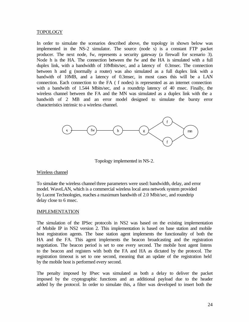
TOPOLOGY In order to simulate the scenarios described above, the topology in shown below was implemented in the NS-2 simulator. The source (node s) is a constant FTP packet producer. The next node, fw, represents a security gateway (a firewall for scenario 3). Node h is the HA. The connection between the fw and the HA is simulated with a full duplex link, with a bandwidth of 10Mbits/sec, and a latency of 0.3msec. The connection between h and g (normally a router) was also simulated as a full duplex link with a bandwith of 10MB, and a latency of 0.3msec, in most cases this will be a LAN connection. Each connection to the FA ( f nodes) is represented as an internet connection with a bandwith of 1.544 Mbits/sec, and a roundtrip latency of 40 msec. Finally, the wireless channel between the FA and the MN was simulated as a duplex link with the a bandwith of 2 MB and an error model designed to simulate the bursty error characteristics intrinsic to a wireless channel.
Topology implemented in NS-2. Wireless channel To simulate the wireless channel three parameters were used: bandwidth, delay, and error model. WaveLAN, which is a commercial wireless local area network system provided by Lucent Technologies, reaches a maximum bandwith of 2.0 Mbit/sec, and roundtrip delay close to 6 msec.
IMPLEMENTATION The simulation of the IPSec protocols in NS2 was based on the existing implementation of Mobile IP in NS2 version 2. This implementation is based on base station and mobile host registration agents. The base station agent implements the functionality of both the HA and the FA. This agent implements the beacon broadcasting and the registration negotiation. The beacon period is set to one every second. The mobile host agent listens to the beacon and registers with both the FA and HA as dictated by the protocol. The registration timeout is set to one second, meaning that an update of the registration held by the mobile host is performed every second. The penalty imposed by IPsec was simulated as both a delay to deliver the packet imposed by the cryptographic functions and an additional payload due to the header added by the protocol. In order to simulate this, a filter was developed to insert both the
s fw h g
f
f
mn

25
delay and the payload. For the simulation of the encryption and authentication of the registration messages, the filter was inserted at the input and output of the registration agents. To simulate the encryption or authentication of all the traffic between nodes, the filter was inserted at the input and output of the nodes. The all-traffic filter was turned off whenever a handoff was taking place, and turned back on at the completion of the registration. The payload and delay used for each security association are presented in the following table.
Delay and payload for IPSec.
ANALYSIS AND RESULTS Simulations of the scenarios described previously were performed, using three different hand-off rates: 17, 25 and 30 seconds. The throughput in each of the cases were measured, as well as the delay penalty imposed by the security protocol: IPSec. All scenarios were simulated with a constant FTP source on top of TCP with a packet size of 1000 bytes.
Throughput The throughput results are shown in Table below. Contrary to expectations, the throughput in wireless environments is driven by the effect of the erratic behavior of the wireless link and not by the delay imposed by the encryption and decryption of the data. As we can see, the throughput in the Basic (only required authentication) and in the VPN scenario (encryption) is almost the same on average. For the 17 and 25second hand-offs, the VPN has better thorughput and for the 30 seconds hand-off, the Basic scenario performed better.
Hand-off (sec) 17 25 30 Throughput
TCP TIME TCP TIME TCP TIME 17 25 30 Avg
Basic 22625 299.526 22731 299.996 22473 299.996 75.53601 75.77101 74.911 75.40601
VPN 23008 299.98 24389 295.547 21882 299.955 76.69845 82.52156 72.95094 77.39032
Throughput comparison
Payload (bytes) Delay factor (secs/bytes)
AH – Transport
32 5.94370E-08
AH – Tunnel 52 5.94370E-08 ESP – Transport
32 2.779625E-07
ESP – Tunnel 52 2.779625E-07
26
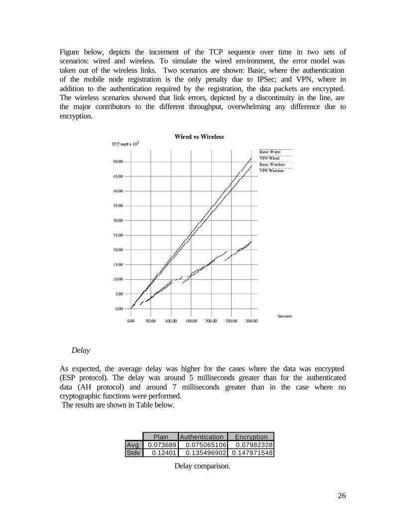
Figure below, depicts the increment of the TCP sequence over time in two sets of scenarios: wired and wireless. To simulate the wired environment, the error model was taken out of the wireless links. Two scenarios are shown: Basic, where the authentication of the mobile node registration is the only penalty due to IPSec; and VPN, where in addition to the authentication required by the registration, the data packets are encrypted. The wireless scenarios showed that link errors, depicted by a discontinuity in the line, are the major contributors to the different throughput, overwhelming any difference due to encryption.
Delay As expected, the average delay was higher for the cases where the data was encrypted (ESP protocol). The delay was around 5 milliseconds greater than for the authenticated data (AH protocol) and around 7 milliseconds greater than in the case where no cryptographic functions were performed. The results are shown in Table below.
Delay comparison.
Plain Authentication EncryptionAvg 0.073689 0.075065106 0.07982328Stdv 0.12401 0.135496902 0.147971548

27
CONCLUSIONS The deployment of security protocols is critical for extending private networks over public backbones. The growth of the mobile community has led to the deployment of protocols such as Mobile IP. Practical applications of Mobile IP will involve communication over a public network to service mobile users, usually attached through a wireless link, as if they were in their home network. The establishment of secure channels involves protocols such as IPSec and IKE. Although the average delay has a direct relationship with the overhead due to the cryptographic functions used for encryption and authentication, IPSec protocols over wireless links do not impose a significant penalty. This is because the main factor in the reduction of the performance is due to the erratic behavior of the channel. References: 1) Perkins, C., Editor, "IP Mobility Support", RFC 2002, October 1996. http://RFC.net/rfc2002.txt 2) S. Deering, R. Hinden, Internet Protocol, Version 6 (IPv6) Specification, RFC 1883, December 1995. http://www.ietf.org/rfc/rfc1883.txt?number=1883 3) D. Johnson,C. Perkins, "Mobility Support in IPv6" <draft-ietf-mobileip-ipv6-07.txt>, IETF Mobile IP Working Group, Nov. 98. http://www.monarch.cs.cmu.edu/internet-drafts/draft-ietf-mobileip-ipv6-07.txt 4) Kent, S., Atkinson, R., "Security Architecture for the Internet Protocol" <draft-ietf- ipsec-arch-sec-02.txt>, November 1997. http://hegel.ittc.ukans.edu/topics/internet/internet-drafts/draft-i/draft-ietf-ipsec-doc.txt 5) S. Kent and R. Atkinson, "IP Authentication Header. Network Working Group", Internet Draft: draft-ietf-ipsec-auth-05.txt, July 1997. http://www.sandelman.ottawa.on.ca/ipsec/1998/03/msg00118.html 6) S. Kent and R. Atkinson, "IP Encapsulating Security Payload (ESP)", Network Working Group, Internet Draft: draft-ietf-ipsec-esp-04.txt, July 1997. http://www.sandelman.ottawa.on.ca/ipsec/1997/05/msg00203.html 7) C. Perkins, "IP Encapsulation within IP", RFC 2003, October 1996. ftp://ftp.isi.edu/in-notes/rfc2003.txt 8) R. Thayer, N. Doraswamy, R. Glenn, "IP Security-Document Roadmap", RFC 2411, November 1998. http://www.ietf.org/rfc/rfc2411.txt?number=2411 9) M. Ishiyama, A. Inoue, A. Shimbo, "Gateway Traversal for Mobile IP using IPSEC primitives" <draft-ishiyama-gateway-traversal-00.txt>, Internet Engineering Task Force,Dec.17 1996

28
http://www-bib.fh-bielefeld.de/epub/doc/idoc/internet-drafts/draft-ishiyama-gateway- traversal-00.txt 10) Matthias Hollick, "The Evolution of Mobile IP Towards Security", German National Research Center for The Evolution of Mobile IP, Oct. 2000. http://www.ito.tu-darmstadt.de/informatik2000/hollick.pdf 11) Zao, Condell, "Use of IPSec in Mobile IP", Internet Draft, draft-ietf-mobilep-ipsec- use-00.txt, November 1997. http://hegel.ittc.ukans.edu/topics/internet/internet-drafts/draft-i/draft-ietf-mobileip- ipsec-use-00.txt 12) Sarah Mocas and Tom Schubert," Formal Analysis of IP Layer Security ", 1997. http://citeseer.nj.nec.com/cache/papers2/cs/1945/ http:zSzzSzwww.cs.pdx.eduzSz~sarahzSzschubert.pdf/mocas97formal.pdf 13) C.Y. Chen, "Mobility with the Internet and IP Networks", MSc Project Dissertation, The University of Birmingham, August 1999. http://web.bham.ac.uk/chency/work/Mobile_IP.pdf 14) Jose Caldera, Dionisio De-Niz, Junichi Nakagawa, "Performance Analysis of IPSec and IKE For Mobile IP on Wireless Environments", Information Networking Institute, Carnegie Mellon University, 2000. http://www.cs.cmu.edu/~dionisio/ipsec-wmip.doc

29