use of phenomena identification and ranking tables in … meeting... · use of phenomena...
TRANSCRIPT
Use of Phenomena Identification and Ranking Tables in the Safety Assessment of Fusion Power Plants
D. Panayotov*, Ph. Jucker
Fusion for Energy (F4E), Josep Pla, 2; Torres Diagonal Litoral B3, Barcelona, E-08019, Spain
*Corresponding author: [email protected]
First IAEA Technical Meeting (TM) on the Safety, Design and Technology of Fusion Power Plants, 3rd -5th May, 2016, IAEA Headquarters, Vienna International Center, Vienna,
Austria

First IAEA TM on the Safety, Design and Technology of Fusion Power Plants, 3rd -5th May, 2016, IAEA Headquarters, Vienna, Austria
OUTLINE
1. Introduction
2. Phenomena Identification and Ranking Tables (PIRTs) definitions and outlook
3. Applications of PIRTs in Fission and Fusion Safety
i. Experimental programs. Separate Effects and Integrated Test Matrices
Development of Fusion Accident Analyses Specifications
ii. Codes’ development
Fusion Code Selection
iii. Code Assessment and Uncertainty Evaluation
Qualification of Fusion Input Models
Fusion Sensitivity Studies and Uncertainty Evaluation
4. Summary and Conclusions
First IAEA TM on the Safety, Design and Technology of Fusion Power Plants, 3rd -5th May, 2016, IAEA Headquarters, Vienna, Austria 2
Disclaimer The views expressed in this presentation are sole responsibility of the authors and do not necessarily reflect the views of the European Commission and the Fusion for Energy.

First IAEA TM on the Safety, Design and Technology of Fusion Power Plants, 3rd -5th May, 2016, IAEA Headquarters, Vienna, Austria
INTRODUCTION: Environment
3
Trends in the development of nuclear power regulations • Integrated Risk informed Decision Making Process (INSAG-25)
• Reactor Technology Assessment
• Harmonization of regulations (Europe)
• Defense in depth (INSAG-10)
• ALARP
Events that affected the nuclear environment – Lessons learned
• Three Mile Island (TMI) accident 1979
• Chernobyl accident 1986
• Fukushima Daiichi accident 2011 => stress tests; Defense in depth evolution
Nuclear power development • Gen III+;
• New Nuclear Power Programmes, new build programs – US, China, India, UK,
• Emerging Nuclear Energy Countries - Belarus, Jordan, Nigeria, Turkey, United Arab Emirates (UAE), Vietnam, Poland, …
• GenIV
• SMR
Requirements Licensing procedures
Fusion energy could also benefit from these
Is the fusion energy impacted?

First IAEA TM on the Safety, Design and Technology of Fusion Power Plants, 3rd -5th May, 2016, IAEA Headquarters, Vienna, Austria
INTRODUCTION: OBJECTIVES
4
Use of fission safety studies in fusion safety
• Enormous experience gained into fission safety
• Regulatory acceptance – current framework and trends
• List the possible synergies: methods and tools to be used with reasonable effort spend on adaptation and qualification to fusion
• There are (more) fission safety approaches, methodologies, methods, tools and experience that would be useful if applied or adapted to fusion safety, as already done for some computer codes (MELCOR and ASTEC for example)
• Where we are in terms of the fission safety evolution and where we need to position our fusion safety methods
• List the existing gaps and development needs of fusion safety
• Propose further works

First IAEA TM on the Safety, Design and Technology of Fusion Power Plants, 3rd -5th May, 2016, IAEA Headquarters, Vienna, Austria
Phenomena identification and ranking tables PIRT
Phenomena identification and ranking tables (PIRT) (often called PIR Technique in non-nuclear applications) is a systematic way of gathering information from experts on a specific subject, and ranking the importance of the information, in order to meet some decision-
making objective, e.g., determining what has highest priority for research on that subject. D. J.
Diamond, Experience Using Phenomena Identification and Ranking Technique (PIRT) for Nuclear Analysis, BNL-76750-2006-CP
Originated and applied in late 80s NRC CSAU Quantifying Reactor Safety Margins: Application of Code Scaling,
Applicability, and Uncertainty Evaluation Methodology to a Large-Break, Loss-of-Coolant, Idaho National Engineering Laboratory, NUREG/CR-5249, December 1989, see also Nuclear Engineering and Design 119 (1) pp 1-117, May 1990
Then developed into a generalised process Wilson, G.E. and B.E. Boyack, “The Role of the PIRT Process in
Experiments, Code Development and Code Applications Associated with Reactor Safety Analysis,” Nuclear Engineering and Design,
186 (1-2): pp 23-37, November 1998 • The PIRT process results in lists of phenomena which are germane to a particular subject (a
very specific evaluation criteria figure-of-merit (FOM)). • The “phenomena” can actually be the condition of a particular reactor/system/ component, a
physical or engineering approximation, a reactor parameter, or anything else that might influence the FOM.
• The process proceeds by ranking these phenomena using some scoring criteria in order to help determine what is most important. That ranking, as well as the rationale for the ranking along with the information obtained to explain the ranking, can assist in decision making.
• An important part of the process is to also identify the uncertainty in the ranking, usually by scoring the knowledge base for the phenomenon.
• Examples of successful PIRT applications exist in thermal-hydraulics, severe accidents, fuels, materials degradation, and nuclear analysis.
5

First IAEA TM on the Safety, Design and Technology of Fusion Power Plants, 3rd -5th May, 2016, IAEA Headquarters, Vienna, Austria
Phenomena identification and ranking tables PIRT
• Phenomena and processes are ranked in the PIRT based on there influence on primary safety criteria, and efforts focused on the most important of these. This process has proven valuable in other contexts and its specifications have been broadened over the years.
• Interpretation of the PIRT depends on details of the objectives, rankings are with respect to o design of an experiment => need for accurate measurements and need for care in scaling
to properly capture its effect in a full-scale system. o improve modelling in a simulation code=> level of detail required in special models
programmed for the phenomenon or process. o sensitivity study the ranking permits a practical statistical analysis. o Phenomena with low importance may be dropped from the uncertainty analysis, or their
impact estimated with bounding calculations. o Highly ranked phenomena are treated individually and perturbations of underlying models
properly included in statistical methodology. o Treatment of phenomena with a medium ranking is done on a case by case basis.
• The value of the final PIRT is directly proportional to the degree of detail in the initial specification of a transient scenario and system in which the scenario occurs. (Wilson and Boyack
(Nuclear Engineering and Design, 186 (1-2): pp 23-37
• creation of a PIRT is an iterative process. After it is first applied results of requested experiments, sensitivity studies, or other results from simulations may require revisions to the original PIRT and associated documentation.John Mahaffy lectures at Pennsylvania State University
• In recent years the value of the PIRT process has been recognized outside the nuclear safety community as an important component of any validation process.
6

First IAEA TM on the Safety, Design and Technology of Fusion Power Plants, 3rd -5th May, 2016, IAEA Headquarters, Vienna, Austria
Phenomena identification and ranking tables PIRT
Nine-Step PIRT Process The PIRT is a structured expert elicitation process designed to support decision making. The process consists of nine distinct steps as follows:
Step 1 — define the issue that is driving the need for a PIRT;
Step 2 — define the specific objectives for the PIRT;
Step 3 — compile and review background information that captures relevant knowledge; identify, compile, and review the current knowledge Data base (sometimes done as step 5);
Step 4 — specify plant and components; divide scenario into phases, i.e. define the hardware and the scenario for the PIRT;
Step 5 — define the evaluation criterion, select key FOM used to judge importance;
Step 6 — identify plausible phenomena, that is, PIRT elements;
Step 7 — develop importance ranking for phenomena, assign importance relative to FOM, document rationale;
Step 8—assess current knowledge level (KL) regarding each phenomena; and
Step 9—document PIRT results, document effort with sufficient coverage that knowledgable reader can understand process and outcome.
S.J. Ball and S.E. Fisher, “Next Generation Nuclear Plant Phenomena Identification and Ranking Tables (PIRTs) (NUREG/CR-6944) Volumes 1 to 6, Volume 1: Main Report, USNRC, March 2008
Westinghouse SMR Small Break LOCA Phenomena Identification and Ranking Table, Westinghouse WCAP-17573-NP, Revision 1 PROJ0797, April 2015
7

First IAEA TM on the Safety, Design and Technology of Fusion Power Plants, 3rd -5th May, 2016, IAEA Headquarters, Vienna, Austria
Phenomena identification and ranking tables PIRT
Elements considered in PIRT Process and Application The scope of PIRT includes the following:
Design
Representative Scenarios
Important Phenomena
Important Data and Models
Available Data and Models
Gaps in Available Data and Models
Westinghouse SMR Small Break LOCA Phenomena Identification and Ranking Table, Westinghouse WCAP-17573-NP, Revision 1 PROJ0797, April 2015
PIRT Objectives • To obtain the functional requirements for an adequate evaluation model for the purpose of
performing the safety analyses • To develop a suitable test matrix intended to provide an adequate evaluation model
assessment database, i.e. identify safety-relevant phenomena, rank importance, and access knowledge base
See an example of PIRT application to BWR CRDA in D. Panayotov, “Westinghouse Realistic BWR Control Rod Drop Accidents Methodology Using POLCA-T Code”, paper ICONE16-48551, 16th International Conference on Nuclear Engineering, Orlando, Florida, USA, May 11-15, 2008
8
PIRT Development
PIRT Application

First IAEA TM on the Safety, Design and Technology of Fusion Power Plants, 3rd -5th May, 2016, IAEA Headquarters, Vienna, Austria
Applications of PIRT
9
Generic applications of PIRTs
A. to identify, categorize, and characterize the phenomena and issues relevant to the risk and safety;
B. prioritize research activities to address the safety significant issues; C. inform decisions regarding the development analytical tools for safety analysis; D. defining the course of accident sequences and defining safety system success
criteria; E. technical basis and cost effective organization for new experimental programs; and F. provide insights for the review of safety analysis and supporting data bases
Some specific applications are provided in the following slides
1) Experimental programs. Separate Effects and Integrated Test Matrices
2) Codes’ development
3) Code Assessment and Uncertainty Evaluation
The presentation will follow a parallel between PIRT applications to fission and fusion safety

First IAEA TM on the Safety, Design and Technology of Fusion Power Plants, 3rd -5th May, 2016, IAEA Headquarters, Vienna, Austria
Methodology for Breeder Blankets Accident Analyses
F4E Methodology for Accident Analyses of Fusion Breeder Blankets makes use of PIRT for the following
• to identify the requirements to be met by the analysis codes and TBS models
• codes assessment within the code selection procedure
• define the sensitivity studies and • perform the uncertainty evaluation
While the work on the first two items is performed during the development of the Accident Analyses Specifications (AAS), the third item is executed in the process of TBS models qualification and the execution of specific accident analysis.
D. Panayotov, A. Grief, B. J. Merrill, P. Humrickhouse, et al., “Methodology for Accident Analyses of Fusion Breeder Blankets”, IEEE SOFE-26 Oral paper #SO12-2, Austin, Texas, May 31 - June 4 2015 conf. CD 978-1-4799-8264-6/15/2015
D. Panayotov, A. Grief, B. J. Merrill, P. Humrickhouse, et al., “Methodology for Accident Analyses of Fusion Breeder Blankets and its Application to Helium-Cooled Pebble Bed Blanket”, ISFNT-12 Oral paper O3A.2, Jeju Island, South Korea, 14-18 September 2015 , Fusion Eng. Des. (2015), http://dx.doi.org/10.1016/j.fusengdes.2015.11.019 in press
Use of PIRTs will be discussed in the following slides with focus on HCLL concept with HCPB relevant applications provided in the additional slides.
Complete list of methodology steps is provided in the additional slides.
10

Experimental programs in FISSION
11
In the mid-seventies experiments and analytical evaluations revealed that multidimensional thermal-hydraulic (TH) phenomena could have significant impact on loss-of-coolant accident (LOCA) transients in PWRs. But even the largest test facilities in operation at that time (e.g., LOFT, LOBI, or PKL) were scaled down geometrically by two or three orders of magnitude. Therefore these facilities could not resolve the issues associated with multidimensional effects on emergency core cooling (ECC).
In addition, safety evaluations in the framework of licensing procedures for nuclear power plants employed conservative assumptions and calculation models to envelope the key parameters of principal safety significance. But in the late seventies the need for best-estimate (BE) evaluation of core damage to be expected during a LOCA was recognized. Such analyses were needed for risk assessment studies. (F. Mayinger, L S. Tong, and M. Nozawa in the DEDICATION/FOREWORD of “Reactor Safety Issues Resolved by the 2D/3D Program”NUREG/IA-0127)
2D/3D Program ”The International Program on the Thermal-Hydraulic Behavior of ECC during the Refill and Reflood Phases of a LOCA in a PWR.“ (1978-1993)
OECD NEA Separate Effects Test Matrix for Thermal-Hydraulic Code Validation, 1994
OECD NEA Integral test facility validation matrix for the assessment of TH codes for LWR LOCA and transients, 1996
See also some other Computer Code Validation Matrices (CCVM) in the additional slides
First IAEA TM on the Safety, Design and Technology of Fusion Power Plants, 3rd -5th May, 2016, IAEA Headquarters, Vienna, Austria

Experimental programs in FISSION
12
2D/3D Program ”The International Program on the Thermal-Hydraulic Behavior of ECC during the Refill and Reflood Phases of a (LB) LOCA in a PWR." 2D/3D Program Work Summary Report, NUREG/IA-0126, GRS-100, MPR-1345, Edited by: P. S. Damerell, J. W. Simons, June 1993
Carried out by Germany, Japan and the United States. Contributory approach was utilized - each country contributed significant effort and all three countries shared the research results • Germany constructed and operated the Upper Plenum Test Facility (UPTF), and
• Japan constructed and operated the Cylindrical Core (CCTF) and the Slab Core Test Facility (SCTF).
• The US contribution consisted of provision of advanced instrumentation to each of the three test facilities, and assessment of the TRAC (Transient Reactor Analysis Code) against the test results.
• Evaluations of the test results were carried out in all three countries. A major analysis program involving the development, assessment and use of a best-estimate (BE) computer code was carried out in the US. TRAC analyses of PWRs and selected tests were also performed by Japan and Germany.
• The technical results and the experience gained by the 2D/3D Program enabled to close the issues about DBA and concentrate in the future on issues arising from BDBA and accident management. Work on these issues further improved the safety of nuclear energy production. (F. Mayinger, L S. Tong, M.
Nozawa in the DEDICATION/FOREWORD of “Reactor Safety Issues Resolved by the 2D/3D Program” NUREG/IA-0127)
• Separate from the 2D/3D Program the USNRC developed a methodology to evaluate TH Code Scaling, Applicability and Uncertainty (CSAU) see the Code Assessment section below.
• The TRAC series were extensively assessed against data. Over the course of the program, results from the assessment calculations performed were continually fed back to the TRAC developers and this contributed significantly to improve the quality of the code. See more in the additional slides
First IAEA TM on the Safety, Design and Technology of Fusion Power Plants, 3rd -5th May, 2016, IAEA Headquarters, Vienna, Austria
FISSION Test Matrices
13
OECD NEA Separate Effects Test (SET) Matrix for TH Code Validation NEA/CSNI/R(93)14, 1994
An internationally agreed SET Validation Matrix for TH system codes has been established as requested by the CSNI. An attempt to record information which has been generated around the world over the last 20 years so that it is more accessible to present and future workers in the field than would otherwise be the case. The methodology that has been developed during the process of establishing SET validation matrix 1. Identification of the phenomena relevant to two-phase flow and TH transients. 2. Characterisation of phenomena. 3. Setting up a catalogue of information sheets on the experimental facilities. 4. Forming a SET facility cross-reference matrix. 5. Selection of relevant facilities related to each phenomenon. 6. Selection of individual tests from the selected facilities, relevant to each phenomenon.
Systematic consolidation of experiment characteristics of 187 test facilities. Sufficiently complete list of relevant phenomena for PWRs and BWRs LOCA and non-LOCA transient applications. To this end 67 phenomena were identified and about 2094 tests are included in the SET matrix.
OECD NEA CSNI Integral test facility validation matrix for the assessment of TH codes for LWR LOCA and transients, NEA/CSNI/R(96)17, 1996, similar to SET matrix • Integral test facilities (ITF) for the validation of BE TH computer codes • Revises and combines the works on PWR (SINDOC(86)12) and BWR (SINDOC(86)13) matrices from 1980s. • Includes the tests performed under the 2D/3D program. • Defines phenomenologically well founded set of experiments, for which comparison of the measured and
calculated parameters forms a basis for establishing the accuracy of the test predictions. A further step – estimation of the capabilities to simulate real plant behaviour was outside of the scope.
• Reminds that the comparison of codes against a limited number of SETs may also be of value. • Attempts to formulate general matrices by including phenomena of interest for most of plants, • Recognises that under certain conditions some special cases of reactors may display phenomena not
adequately addressed by the matrices produced. Additional validation might be needed.
First IAEA TM on the Safety, Design and Technology of Fusion Power Plants, 3rd -5th May, 2016, IAEA Headquarters, Vienna, Austria

FUSION PIRT: DEVELOPMENT OF THE HCLL AAS
14
A. Phenomena identification tables and Required Code Models two stage process
• review of existing or similar analysis results • review of phenomena based on the physical processes imposed by the fault, system design, operating
conditions, safety functions and materials of construction
Consolidation of the phenomena was carried out to define the requirements for the code models and correlations
final in-depth review of contributing factors, conditions and phenomena was undertaken using a bottom up approach to identify factors, conditions and phenomena that could present a modelling requirement and potentially influence the code selection process
The phenomena evaluated are grouped under the following sub-headings: • Power source • Flow • Heat transfer • Phase change • Lithium lead (PbLi) modelling • Chemical reactions • Non-condensible gases • Material properties • Numerical coupling • System modelling (control and instrumentation)
An extract of the complete 8 pages PIRT for the power source and PbLi modelling is presented in Table 1.
See the HCPB TBS Table in the additional slides.
Table 1 List of HCLL TBS Phenomena for power source and PbLi modellling Phenomenon/Parameter Location Impact on Faults
Power Source
Nuclear heating (normal operation) Port Plug (PP) frame, structures, breeder unit (BU), FW, shield.
Temperature response of structures and inventories
Plasma surface heat fluxes (operation and disruption)
PP frame, structures, BU, FW, shield.
Temperature response of structures and inventories.
Decay heat PP frame, structures, BU, FW, shield.
Temperature response of structures and inventories.
PbLi Modelling
Heat transfer BU, PbLi ancillary loop. Temperature response of structures and inventories.
Chemical reactions Lithium with steam/air BU and PbLi ancillary loop Moveable source of thermal inertia and decay heat.
Power source (nuclear heating and decay heat)
BU, TBM box, VV Steam: LiOH and H2 production and heat release. Air: Li2O production and heat release..
Flow/mixing of liquids - PbLi and water VV. Rate and overall reaction of compounds.
PbLi – impact of magneto-hydrodynamic (MHD) phenomena
BU.
In normal operation, magnetic fields generate significant contribution to PbLi pressure drop across TBM and influences the local flow distribution and heat transfer. In accident, mainly affect dynamics of PbLi flow.
PbLi Flow in normal operation and in faults
BU,VV. Rate of draining of BU. PbLi flow regime within VV (droplet size, pooling). Heat transfer from spilt PbLi.
Material Properties BU, PbLi loop, VV (faulted). Chemical reaction, solidification
First IAEA TM on the Safety, Design and Technology of Fusion Power Plants, 3rd -5th May, 2016, IAEA Headquarters, Vienna, Austria

FISSION Codes’ development
15
TRAC Codes (TRAC-P & TRAC-B) development following the 2D/3D Program The TRAC series of computer codes were extensively assessed against data from the 2D/3D Program. Over the course of the program, results from the assessment calculations performed in the program were continually fed back to the TRAC developers and this contributed significantly to improve the quality of the code
RELAP development within the International Code Assessment Program (ICAP) see below
Coupled codes • Thermal-hydraulics (TH) and (core) neutron kinetics (NK): RELAP/RAMONA, TRAC/NEM, QUABOX/CUBBOX-
ATHLET, ATHLET/DYN3D, TRAC/PARCS, early W POLCA-T versions • Thermal-hydraulics (TH) and (fuel) thermal-mechanics • System TH code with CFD • System TH code with severe accident code: SCDAP/RELAP5, SCDAP/RELAP-3D, RELAP/SCDAPSIM Way of coupling: Internal, external and parallel codes coupling,
Direct and iterative loose coupling
CRISSUE-S project Neutronics/Thermal-hydraulics Coupling in LWR Technology, State-Of-the-Art Report F. D’Auria, A. Bousbia Salah, G.M. Galassi, J. Vedovi, F. Reventós, A. Cuadra, J.L. Gago, A. Sjöberg, M. Yitbarek, O. Sandervåg, N. Garis, C. Anhert, J.M. Aragonés, G. Verdù, R. Mirò, J. Hadek, J. Macek, K. Ivanov, R. Uddin, E. Sartori, U. Rindelhardt, U. Rohde, D. Panayotov, et al.,
WP 1: Vol. 1 CRISSUE-S – WP1: Data Requirements and Databases Needed for Transient Simulations and Qualification”, OECD/NEA Report No. 4452, ISBN 92-64-02083-7, Paris (F), 2004, https://www.oecd-nea.org/science/docs/pubs/nea4452-crissue-s-vol1.pdf WP 2: Vol. 2 CRISSUE-S – WP2: State-of-the-art Report (REAC-SOAR)”, OECD/NEA Report No 5436, ISBN 92-64-02084-5, Paris (F), 2004, https://www.oecd-nea.org/science/docs/pubs/nea5436-crissue-s-vol2.pdf WP 3: Vol. 3 CRISSUE-S – WP3: Achievements and Recommendations Report (REAC-SOAR)”, OECD/NEA Report No 5434, ISBN 92-64-02085-3, Paris (F), 2004, https://www.oecd-nea.org/science/docs/pubs/nea5434-crissue-s-vol3.pdf
Coupling of different codes that model the same phenomena or processes by different equation systems and constitutive equations and make use of different solvers may lead to non-physical numerical oscillations and perturbations in the solutions and the simulation results.
First IAEA TM on the Safety, Design and Technology of Fusion Power Plants, 3rd -5th May, 2016, IAEA Headquarters, Vienna, Austria

FISSION Codes’ development
16
Integrated codes: W POLCA-T, RELAP-3D, TRACE • System TH code, NK and fuel thermal-mechanics equations in a single matrix (solved by the same solver) - W
POLCA-T D. Panayotov, ”OECD/NRC BWR Turbine Trip Benchmark: Simulation by POLCA-T Code”, Nuclear Science and Engineering, volume 148, pp. 247-255, October (2004). D. Panayotov, “Advantages of Westinghouse BWR Control Rod Drop Accidents Methodology Utilizing Integrated POLCA-T Code”, paper Log229, PHYSOR-2008 “Nuclear Power: A Sustainable Resource”, Interlaken, Switzerland, September 14-19, 2008. D. Panayotov, U. Bredolt, H. Lindgren ”POLCA-T – A Coupled Multi-Physics Tool for Design and Safety Analyses”, Invited paper Mathematics and Computation (M&C 2005), Avignon, France, September 12-15, 2005. U. Bredolt, D. Panayotov, “POLCA-T A Coupled 3D Neutron Kinetic and Thermal Hydraulic Code for Analysis of BWR’s”, paper 13-50054 13th International Conference on Nuclear Engineering (ICONE 13), Beijing, China, May 16-20, 2005.
• System TH code and NK - RELAP-3D, TRACE
NRC Codes Consolidation => TRACE 5.0 integrated code
Integrated EU platforms: NURESIM, NIRISP & NURESAFE projects • Nuclear data; Monte Carlo codes; Lattice codes; Core simulators; • Subchannel codes; fuel behaviour (TM) codes; System TH codes; • CFD, etc.
Consortium for Advanced Simulation of Light Water Reactors (A DOE Energy Innovation Hub) – • Virtual Environment for Reactor Applications (VERA), • Application to W AP-1000
DOE Energy Nuclear Energy Advanced Modeling & Simulation (NEAMS) Program • NEAMS ToolKit 3D, high-fidelity, coupled-physics simulation capability for advanced reactors • BISON fuel performance • RELAP-7 development
First IAEA TM on the Safety, Design and Technology of Fusion Power Plants, 3rd -5th May, 2016, IAEA Headquarters, Vienna, Austria
FUSION Code Assessment and Selection
17
A code assessment is performed to assess the ability of simulation codes to model the phenomena listed in the Phenomena Identification Tables (described above). Further considerations, such as code verification status, may be set according to the objective of the work and its scope. For the HCLL and HCPB TBSs, additional code assessment criteria included the ability of the codes to resolve local and 2D/3D effects and consistency with (existing) ITER safety analyses. Furthermore, the code selection process has been limited to the assessment of different versions of the RELAP5 and MELCOR codes, as prescribed by F4E. The specific code versions that have been considered are:
• RELAP5/MOD3.3 and RELAP5-3D;
• the fusion adapted MELCOR 1.8.2, 1.8.5 (multi-fluids) and 1.8.6 code versions produced by Idaho National Laboratory (INL);
• the ‘standard’ MELCOR 1.8.6 and MELCOR 2.1 codes, produced by Sandia National Laboratory (SNL).
Highlighted are the codes/versions selected for HCLL and HCPB accident analyses and one used for ITER analyses
The individual versions of the MELCOR and RELAP5 codes have, in many respects, similar capabilities and attributes. Therefore, an overall assessment of the MELCOR and RELAP5 codes was performed whilst highlighting particular strengths of the individual code versions to represent specific phenomena. As part of this process specific phenomena identified within the PIRT are discussed in terms of their significance to fault progression and ultimately to the release of radioactivity to the environment.
Advantages of individual codes and versions are discussed in the additional slide
First IAEA TM on the Safety, Design and Technology of Fusion Power Plants, 3rd -5th May, 2016, IAEA Headquarters, Vienna, Austria

FUSION PIRT: HCLL Code Assessment and Selection
18
B. Code assessment and selection In Table 2 the list of phenomena presented in Table 1 is repeated with an associated statement indicating the ability of the codes’ models to represent specific phenomenon Table 2 HCLL TBS Code Assessment
Parameter / Phenomenon
MELCOR Uncerta
inty RELAP5
Uncertainty
Power Source
Nuclear heating (operation)
Point source heating within heat structures
L Point source heating in heat structures.
L
Plasma surface heat fluxes (operation and disruption)
Surface heat source model. L
Internal heat source applied to the boundary heat structure node or user controlled heat flux at the surface.
L
Decay heat Point source heating in heat structures L Point source heating in heat structures
L
PbLi Modelling
Heat transfer,
Heat transfer through the PbLi is dominated by conduction, heat transfer to the adjacent FW, cooling plates (CP) and Side Wall (SW) will be a mixture of convection and conduction. Available in fusion version 1.8.5 only. Due to the low flowrate of PbLi a heat structure and control function can be adopted MELCOR 1.8.2.
M / L
The same comment on the MELCOR code versions also applies to the RELAP5 codes. Possible with RELAP5-3D
M / L
Power source (nuclear heating and decay heat)
Point source heating within heat structures
L Point source heating in heat structures.
L
Chemical reactions Lithium with steam/air;
Not dynamic but can be bounded by a control function approach.
M / L Not dynamic but can be bounded by a control function approach.
M / L
Flow/mixing of liquids - PbLi and water
There is no mechanistic model to predict the interaction between flows of PbLi and water and the subsequent chemical reaction. It is noted that the heat transfer from split PbLi will increase the pressurisation of the VV which needs to be captured in the analyses.
H (bound
ed)
The same comment on the MELCOR code versions also applies to the RELAP5 codes.
H (bound
ed)
PbLi – impact of MHD phenomena
The constraints of the MHD phenomena on the flowing liquid Pb-Li can be modelled by suitable inputs for the loss coefficients (fusion adapted MELCOR 1.8.5). However, in most faults the PbLi flowrate is very low. MHD effects also impact the local flow distribution which in turn influences the wall-to-fluid heat transfer.
M
The MHD effects on the flowing PbLi can be modelled in RELAP5-3D through user input loss coefficients. However, the impact is judged to be low due to the low flowrate of the PbLi. As discussed for MELCOR the MHD effects can influence the local wal-to-fluid heat transfer.
M
PbLi Flow in operation and in faults.
Can only be modelled by fusion adapted version of MELCOR 1.8.5.
H This can only be simulated by RELAP5-3D.
H
Material Properties Material Property table input. L Material Property table input. L
Considerations: • For the representation of the ITER machine within the HCLL
TBS safety studies, it is assumed that the ‘pedigreed’ fusion-adapted MELCOR version 1.8.2 code will be retained..
• MELCOR 2.1: the complete range of currently available fusion related code modifications has not been applied consistently to each of the MELCOR standard code versions.
• In terms of modelling capability the main contenders are fusion adapted MELCOR 1.8.5 and fusion adapted MELCOR 1.8.6.
• In terms of verification the pedigreed fusion-adapted MELCOR version 1.8.2 has the advantage of a line-by-line review of the fusion adapted updates. However, fusion adapted versions of 1.8.5 and 1.8.6 has been the subject of separate comparison studies with the pedigreed version and has shown very similar agreement.
Based on the contributing factors it is judged that the most suitable code version to perform the safety assessment for the HCLL TBS is MELCOR 1.8.5. Given the distinct advantages of being able to mechanistically represent the physical response of liquid PbLi the RELAP5-3D code is selected to support MELCOR 1.8.5.
extract of the complete 12 pages PIRT
First IAEA TM on the Safety, Design and Technology of Fusion Power Plants, 3rd -5th May, 2016, IAEA Headquarters, Vienna, Austria

FISSION Code Assessment and Uncertainty Evaluation
19
NRC CSAU: Separate from the 2D/3D Program the USNRC developed a methodology to evaluate thermal-
hydraulic code scaling, applicability and uncertainty (CSAU). Quantifying Reactor Safety Margins: Application of Code
Scaling, Applicability, and Uncertainty Evaluation Methodology to a Large-Break, Loss-of-Coolant," Idaho National Engineering Laboratory, NUREG/CR-5249, Dec 1989
• demonstrate that uncertainties in complex phenomena can be quantified, • structured, traceable, and practical methodology , as is needed in the regulatory arena, • systematic and comprehensive methodology addresses and integrates the scenario, experiments, code, and
plant to resolve questions concerned with: (a) code capability to scale-up processes from test facility to fill-scale NPPs; (b) code applicability to safety studies of a postulated accident scenario in a specified NPP; and (c) quantifying uncertainties of calculated results.
• The methodology combines a top-down approach to define the dominant phenomena with a bottom-up approach to quantify uncertainty. The methodology is able to address both uncertainties for which bias and distribution are quantifiable and uncertainties for which only a bounding value is quantifiable.
• The methodology is general and therefore applicable to a variety of scenarios, plants, and codes.
International Code Assessment Program (ICAP) began in 1985 and was directed to:
• Support the efforts of the U.S. NRC to determine the ability of advanced TH codes to appropriately represent important physical phenomena and support the quantitative determination of the accuracy of these codes;
• Share user experience on code assessment and to present a well documented assessment data base; • Share experience on code errors and inadequacies and cooperate in removing the deficiencies to maintain a
single, internationally recognized version of each code; and • Establish and improve user guidelines for applying the code. RELAP5 code assessment reviews conducted through 1991 at INEL plus the TRAC-BWR assessment reviews completed during 1992. Code assessments of RELAP5/MOD2, RELAP5/MOD3, TRAC-BF1.
62 assessment studies identified a number of code deficiencies in all three codes. The deficiencies particular to RELAP5/MOD2 were used as input to improve the MOD2 code and thus produce RELAP5/MOD3. Deficiencies specific to TRAC-BWR and RELAP5/MOD3 have been summarized to serve as input for upcoming code improvement efforts.
First IAEA TM on the Safety, Design and Technology of Fusion Power Plants, 3rd -5th May, 2016, IAEA Headquarters, Vienna, Austria

FISSION Code Assessment and Uncertainty Evaluation
20
Automated Code Assessment Program (ACAP) software platform (US NRC) R.F. Kunz, G.F. Kasmala, C.J. Murray, J.H. Mahaffy, An Automated Code Assessment Program for Determining Systems Code Accuracy, OECD/CSNI Workshop on Advanced Thermal-Hydraulic and Neutronic Codes: Current and Future Applications, Barcelona, SPAIN, 10-13 April, 2000 NEA/CSNI/R(2001)2/VOL1
OECD International Standard Problems (ISPs) programme has contributed to code assessment.
CSNI International Standard Problems (ISP) Brief descriptions (1975-1999), NEA/CSNI/R(2000)5, March 2000
OECD CSNI Uncertainty Methods Study on Code Uncertainty 1995-98 Report on the Uncertainty Methods
Study, NEA/CSNI/R(97)35 vol. 1, June 1998
OECD BEMUSE project (Best-Estimate Methods – Uncertainty and Sensitivity Evaluation) 2004-2011
Application of BE methods to a LB LOCA in the primary system of a NPP: 1st step ISP-13 LOFT L2-5; 2nd: NPP LB LOCA; two methods: Code with (the capability) for Internal Assessment of Uncertainty (CIAU) and probabilistic.
BEMUSE Phase VI Report: Status on the area, classification of the methods, conclusions and recommendations, NEA/CSNI/R(2011)4, March 2011
Numerous Code V&V studies and benchmarks projects
OECD Benchmark for Uncertainty Analysis in Best-Estimate Modelling (UAM) for Design, Operation
and Safety Analysis of LWRs (OECD LWR UAM Benchmark)
OECD Benchmark for Uncertainty Analysis in Best-Estimate Modelling (UAM) for Design, Operation and Safety Analysis of LWRs (OECD LWR UAM Benchmark), Expert Group on Uncertainty Analysis Third Workshop (UAM-3), NEA/NSC/DOC(2009)11, June2009
First IAEA TM on the Safety, Design and Technology of Fusion Power Plants, 3rd -5th May, 2016, IAEA Headquarters, Vienna, Austria

FUSION QUALIFICATION OF THE HCLL TBS MODELS
21
Test matrix: (12 cases with 19 variations executed in 24 code runs) • Comparison with finite element design analyses • Code-to code comparison: normal operation and test transients • Sensitivity and uncertainty studies in more complex accidents • TABLE 3. HCLL TBS MODEL QUALIFICATION SUMMARY
# Case Title Scenario and runs executed
Comparison with the TBM design analyses 1 TBM steady-state at
full plasma power using ‘No Back Plate Convection’ (NBPC) model variant
Steady-state TBM model analyses to support comparison with design finite element results (a) Preliminary MELCOR model comparison with FE data. (b) Revised MELCOR analysis using adjusted model (c) RELAP5 analysis, incorporating model adjustments from
MELCOR analysis
2 TBM 400 s plasma power pulse using NBPC model variant
TBM model analysis of a 400 s power pulse to support comparison with DDD finite element analysis. MELCOR and RELAP5 simulation
3 TBM response to 10 s MARFE power excursion using NBPC model variant
TBM model analysis of a 10 second period of enhanced FW surface heating (starting from full power steady state conditions) to support comparison with design finite element analysis. MELCOR and RELAP5 simulation
4 TBM steady state at full plasma power
TBM model steady-state analysis includes modelling of convective heat transfer at the TBM back plates. MELCOR and RELAP5 simulation
Analysis of HCLL TBS normal operation 5 TBS full plasma power
pulse 400 s
TBS model analysis of a 400 s plasma power pulse. Model set up to reflect boundary conditions from HCLL TBS SADL. Includes port plug, HCS, TBM and PbLi ancillary system models. MELCOR and RELAP5 simulation
TBS Fault sequence test cases
6 TBS test 1 LOFA LOFA sequence initiated by loss of HCS circulator during 400 seconds power pulse. Circulator failure occurs 100 seconds after start of pulse, MELCOR and RELAP5 simulation
7 TBS test 2 In-vessel LOCA
In-vessel FW LOCA occurring close to end of 400 s power pulse. Helium leak from FW to VV occurs at 429 seconds. No PbLi leak. MELCOR and RELAP5 simulation
8 TBS test 3 In-vessel LOCA followed by PbLi leak into VV
In-vessel FW LOCA occurring close to end of 400 s power pulse, with PbLi leak 10 s later. Simulated by MELCOR only, due to RELAP code issues preventing PbLi drain down / leak modelling.
# Case Title Scenario and runs executed
Sensitivity studies 9 S1: TBM nodalisation
sensitivity 1
FW coolant channel nodalisation study. Impact of an 8 CVH node model of FW coolant channel investigated. MELCOR simulation only (a) Full plasma power steady-state (b) 400 s plasma pulse
10 S2: HCS isolation valve closure time study
In-vessel FW LOCA close to end of 400 s power pulse, with variation of the HCS isolation valve closure characteristics. MELCOR simulation only
Base case 2 second processing delay followed by valve closure over 2 seconds
Case 2 1 second processing delay followed by valve closure over 2 seconds.
Case 3 4 seconds processing delay followed by valve closure over 2 seconds.
Case 4 No HCS isolation valve closure
11 S3: PbLi draining & leakage into VV
PbLi leak to VV occurs close to end of 400 s power pulse, with variation of leak path models. Investigate PbLi leak location and representation on leak rate and total leak flow. MELCOR simulation only
Case 1BU-1 Circular leak at mid height of BU1 represented by one MELCOR FL.
Case 2BU-1&2 Circular leaks at mid height of BU1 and BU2
Case 2BU-1&3 Circular leaks at mid height of BU1 and BU3
Case 2BU-1&8 Circular leaks at mid height of BU1 and BU8
Case SLIT Slit-shaped leak extending over the complete height of BU1. In all cases the same leak area as in 1-BU1 has been used.
12 S4: MHD forces and PbLi isolation valve (IV) study
PbLi leak to VV occurs close to end of 400 s power pulse, with variation of MHD force and TBM PbLi isolation valve behavior. MELCOR simulation only
MHD-off-IV-open MHD forces terminated prior to PbLi leak; PbLi loop isolation valves remain open throughout transient
MHD-on-IV-open MHD forces persist throughout transient and PbLi loop isolation valves remain open
MHD-off-IV-close MHD forces terminated prior to PbLi leak; TBM PbLi loop isolation valves close normally
MHD-on-IV-close MHD forces persist throughout transient; TBM PbLi loop isolation valves close normally
Final step: Code-to code comparison for 32h LOOP accident
First IAEA TM on the Safety, Design and Technology of Fusion Power Plants, 3rd -5th May, 2016, IAEA Headquarters, Vienna, Austria
FUSION BREEDING BLANKET UNCERTAINTY EVALUATION
22
Uncertainty analysis The impact of uncertainties associated with the fault analyses needs to be addressed to provide sufficient confidence in the level of conservatism in the results. The approach adopted for the TBS fault analyses reflects the maturity of the design of the TBS and ITER machine and takes the form of a uncertainty PIRT assessment and associated sensitivity calculations. It is judged that full quantification of the uncertainty is not justified at this stage of the project; however, it is
intended that significant areas of uncertainty and ‘cliff edge’ effects on the analysis results will be identified. Uncertainty Methods: An expert review of areas of uncertainty followed by the performance of sensitivity analyses. Advantages of selected method are provided in the additional slides Sources of Uncertainty (see additional slides for detail)
Similar sources of uncertainty exist in the application of codes models to represent complex physical phenomena. These have been documented in various publications and papers worldwide.
1. Code models: Code Validation and Verification 2. System Model Representation include: Nodalisation; Model limitations/inaccuracies and User effect 3. Plant operating parameters are usually set at conservative and bounding values. 4. Effect of Scale: The effects of scale are usually addressed by assessing the developed facility models against
Integral Tests.
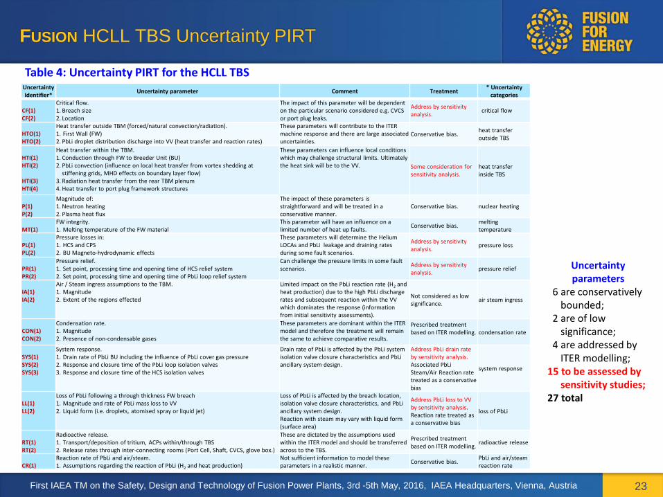
Development of a PIRT for the HCLL TBS A PIRT for the HCLL TBS, presented in Table 4, has been produced based on a review of the scenarios to be analysed, the design of the HCLL TBS models and the findings of the phenomena identification and code selection reported above. The PIRT in Table 4 also identifies the methods that will be used within the accident analysis to account for the impact of each uncertainty, stating where conservative data values might be used to bound the impact of an uncertainty, and where a sensitivity study may be necessary. The potential impact of the identified uncertainties on individual accident sub-sequences is summarised in Table A-4 (additional slides).
First IAEA TM on the Safety, Design and Technology of Fusion Power Plants, 3rd -5th May, 2016, IAEA Headquarters, Vienna, Austria
FUSION HCLL TBS Uncertainty PIRT
23
Table 4: Uncertainty PIRT for the HCLL TBS Uncertainty Identifier*
Uncertainty parameter Comment Treatment * Uncertainty
categories CF(1) CF(2)
Critical flow. 1. Breach size 2. Location
The impact of this parameter will be dependent on the particular scenario considered e.g. CVCS or port plug leaks.
Address by sensitivity analysis.
critical flow
HTO(1) HTO(2)
Heat transfer outside TBM (forced/natural convection/radiation). 1. First Wall (FW) 2. PbLi droplet distribution discharge into VV (heat transfer and reaction rates)
These parameters will contribute to the ITER machine response and there are large associated uncertainties.
Conservative bias. heat transfer outside TBS
HTI(1) HTI(2) HTI(3) HTI(4)
Heat transfer within the TBM. 1. Conduction through FW to Breeder Unit (BU) 2. PbLi convection (influence on local heat transfer from vortex shedding at
stiffening grids, MHD effects on boundary layer flow) 3. Radiation heat transfer from the rear TBM plenum 4. Heat transfer to port plug framework structures
These parameters can influence local conditions which may challenge structural limits. Ultimately the heat sink will be to the VV. Some consideration for
sensitivity analysis. heat transfer inside TBS
P(1) P(2)
Magnitude of: 1. Neutron heating 2. Plasma heat flux
The impact of these parameters is straightforward and will be treated in a conservative manner.
Conservative bias. nuclear heating
MT(1)
FW integrity. 1. Melting temperature of the FW material
This parameter will have an influence on a limited number of heat up faults.
Conservative bias. melting temperature
PL(1) PL(2)
Pressure losses in: 1. HCS and CPS 2. BU Magneto-hydrodynamic effects
These parameters will determine the Helium LOCAs and PbLi leakage and draining rates during some fault scenarios.
Address by sensitivity analysis.
pressure loss
PR(1) PR(2)
Pressure relief. 1. Set point, processing time and opening time of HCS relief system 2. Set point, processing time and opening time of PbLi loop relief system
Can challenge the pressure limits in some fault scenarios.
Address by sensitivity analysis.
pressure relief
IA(1) IA(2)
Air / Steam ingress assumptions to the TBM. 1. Magnitude 2. Extent of the regions effected
Limited impact on the PbLi reaction rate (H2 and heat production) due to the high PbLi discharge rates and subsequent reaction within the VV which dominates the response (information from initial sensitivity assessments).
Not considered as low significance.
air steam ingress
CON(1) CON(2)
Condensation rate. 1. Magnitude 2. Presence of non-condensable gases
These parameters are dominant within the ITER model and therefore the treatment will remain the same to achieve comparative results.
Prescribed treatment based on ITER modelling.
condensation rate
SYS(1) SYS(2) SYS(3)
System response. 1. Drain rate of PbLi BU including the influence of PbLi cover gas pressure 2. Response and closure time of the PbLi loop isolation valves 3. Response and closure time of the HCS isolation valves
Drain rate of PbLi is affected by the PbLi system isolation valve closure characteristics and PbLi ancillary system design.
Address PbLi drain rate by sensitivity analysis. Associated PbLi Steam/Air Reaction rate treated as a conservative bias
system response
LL(1) LL(2)
Loss of PbLi following a through thickness FW breach 1. Magnitude and rate of PbLi mass loss to VV 2. Liquid form (i.e. droplets, atomised spray or liquid jet)
Loss of PbLi is affected by the breach location, isolation valve closure characteristics, and PbLi ancillary system design. Reaction with steam may vary with liquid form (surface area)
Address PbLi loss to VV by sensitivity analysis. Reaction rate treated as a conservative bias
loss of PbLi
RT(1) RT(2)
Radioactive release. 1. Transport/deposition of tritium, ACPs within/through TBS 2. Release rates through inter-connecting rooms (Port Cell, Shaft, CVCS, glove box.)
These are dictated by the assumptions used within the ITER model and should be transferred across to the TBS.
Prescribed treatment based on ITER modelling.
radioactive release
CR(1)
Reaction rate of PbLi and air/steam. 1. Assumptions regarding the reaction of PbLi (H2 and heat production)
Not sufficient information to model these parameters in a realistic manner.
Conservative bias. PbLi and air/steam reaction rate
Uncertainty parameters
6 are conservatively bounded;
2 are of low significance;
4 are addressed by ITER modelling;
15 to be assessed by sensitivity studies;
27 total
First IAEA TM on the Safety, Design and Technology of Fusion Power Plants, 3rd -5th May, 2016, IAEA Headquarters, Vienna, Austria
Summary on PIRT Applications to FUSION SAFETY
24
• The PIRTs are powerful tool (as demonstrated in F4E developed Methodology for Fusion Breeder Blankets Accident Analysis)
o to identify the phenomena that take place in the accidents;
o to identify the requirements to be met by the analysis codes;
o to assess and select the analysis codes.
o to define the sensitivity studies and
o to evaluate the uncertainties
• Qualification of the models by comparison with finite element analyses and code-to-code comparisons proved that development of flexible generic TBS models to handle wide spectra of accidents with minor adaptation is possible.
• Additional testing and verification is still to be done before using the coupling of different codes or code versions in order to simulate multi-fluid flows and phenomena overcoming the codes’ limitations.
• Further sensitivity studies on reference scenarios were performed to confirm the selected uncertainty evaluation method. These were done in the comparison of the HCLL and HCPB MELCOR and RELAP-3D simulations of 32 hours loss of offsite power. Further executed HCLL and HCPB scenarios consider loss of coolant flow accident LOFA and LOFA with breeder unit failure i.e. in-breeder LOCA. In total 8 base case and 16 sensitivity runs had been executed for the three reference scenarios concerned.
First IAEA TM on the Safety, Design and Technology of Fusion Power Plants, 3rd -5th May, 2016, IAEA Headquarters, Vienna, Austria
CONCLUSIONS
25
• PIRT have to be applied to fusion safety wider in order to o Identify the DEMO relevant phenomena in a systematic way o Identify the needs/gaps for experimental studies on both separate effects and integral and
plan the facilities and experimental campaigns o Systematize the available experimental data into matrices and data bases o perform the sensitivity analyses and evaluate the uncertainties o Computer codes assessment - identify the existing gaps and development needs o ... PIRT has to be incorporated into the Fusion Safety Assessment
• Fission safety methodologies, methods and tools are useful when adapted to fusion safety computer codes development, assessment and uncertainty evaluation has been discussed. These might be further complemented looking into fusion o Regulatory framework development o PRA and PSA development and application o Gen IV cooperation and development o Aspects of CFD applications to nuclear safety
• Management/preservation of the experimental data is crucial for computer codes and safety methods development (knowledge management, reference case, licensing, etc.)
First IAEA TM on the Safety, Design and Technology of Fusion Power Plants, 3rd -5th May, 2016, IAEA Headquarters, Vienna, Austria
Follow us on:
www.f4e.europa.eu
www.twitter.com/fusionforenergy
www.youtube.com/fusionforenergy

27
Additional Slides
First IAEA TM on the Safety, Design and Technology of Fusion Power Plants, 3rd -5th May, 2016, IAEA Headquarters, Vienna, Austria
First IAEA TM on the Safety, Design and Technology of Fusion Power Plants, 3rd -5th May, 2016, IAEA Headquarters, Vienna, Austria
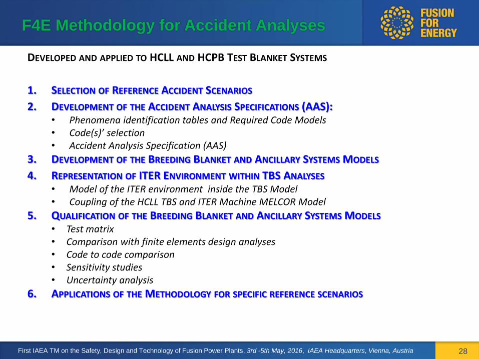
F4E Methodology for Accident Analyses
DEVELOPED AND APPLIED TO HCLL AND HCPB TEST BLANKET SYSTEMS
1. SELECTION OF REFERENCE ACCIDENT SCENARIOS
2. DEVELOPMENT OF THE ACCIDENT ANALYSIS SPECIFICATIONS (AAS): • Phenomena identification tables and Required Code Models • Code(s)’ selection • Accident Analysis Specification (AAS)
3. DEVELOPMENT OF THE BREEDING BLANKET AND ANCILLARY SYSTEMS MODELS
4. REPRESENTATION OF ITER ENVIRONMENT WITHIN TBS ANALYSES • Model of the ITER environment inside the TBS Model • Coupling of the HCLL TBS and ITER Machine MELCOR Model
5. QUALIFICATION OF THE BREEDING BLANKET AND ANCILLARY SYSTEMS MODELS • Test matrix • Comparison with finite elements design analyses • Code to code comparison • Sensitivity studies • Uncertainty analysis
6. APPLICATIONS OF THE METHODOLOGY FOR SPECIFIC REFERENCE SCENARIOS
28
FISSION Experimental programs and Test Matrices
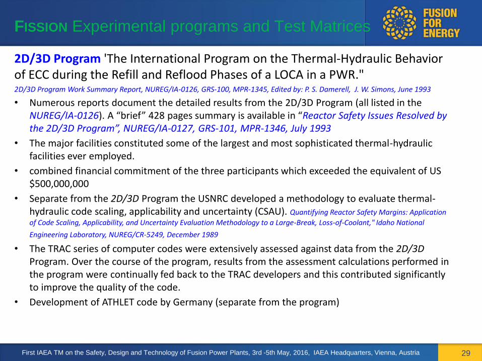
29
2D/3D Program 'The International Program on the Thermal-Hydraulic Behavior of ECC during the Refill and Reflood Phases of a LOCA in a PWR." 2D/3D Program Work Summary Report, NUREG/IA-0126, GRS-100, MPR-1345, Edited by: P. S. Damerell, J. W. Simons, June 1993
• Numerous reports document the detailed results from the 2D/3D Program (all listed in the NUREG/IA-0126). A “brief” 428 pages summary is available in “Reactor Safety Issues Resolved by the 2D/3D Program”, NUREG/IA-0127, GRS-101, MPR-1346, July 1993
• The major facilities constituted some of the largest and most sophisticated thermal-hydraulic facilities ever employed.
• combined financial commitment of the three participants which exceeded the equivalent of US $500,000,000
• Separate from the 2D/3D Program the USNRC developed a methodology to evaluate thermal-hydraulic code scaling, applicability and uncertainty (CSAU). Quantifying Reactor Safety Margins: Application
of Code Scaling, Applicability, and Uncertainty Evaluation Methodology to a Large-Break, Loss-of-Coolant," Idaho National
Engineering Laboratory, NUREG/CR-5249, December 1989
• The TRAC series of computer codes were extensively assessed against data from the 2D/3D Program. Over the course of the program, results from the assessment calculations performed in the program were continually fed back to the TRAC developers and this contributed significantly to improve the quality of the code.
• Development of ATHLET code by Germany (separate from the program)
First IAEA TM on the Safety, Design and Technology of Fusion Power Plants, 3rd -5th May, 2016, IAEA Headquarters, Vienna, Austria

FISSION Experimental programs and Test Matrices
30
Other Computer Code Validation Matrices (CCVM)
VVER reactors
OECD NEA Validation Matrix for the Assessment of Thermal-Hydraulic Codes for VVER LOCA and Transients, NEA/CSNI/R(2001)4, June 2001
Severe Accidents
OECD NEA In-vessel core degradation Code Validation Matrix Update 1996-1999, NEA/CSNI/R(2001)21, February 2001
Containment
OECD NEA Containment Code Validation Matrix, NEA/CSNI/R(2014)3, May-2014
This CCVM contains a description of 127 phenomena, broken down into 6 categories: • Containment Thermal-hydraulics Phenomena • Hydrogen Behaviour (Combustion, Mitigation and Generation) Phenomena • Aerosol and Fission Product Behaviour Phenomena • Iodine Chemistry Phenomena • Core Melt Distribution and Behaviour in Containment Phenomena • Systems Phenomena Hydrogen phenomena tests that are of high interest to fusion safety
First IAEA TM on the Safety, Design and Technology of Fusion Power Plants, 3rd -5th May, 2016, IAEA Headquarters, Vienna, Austria
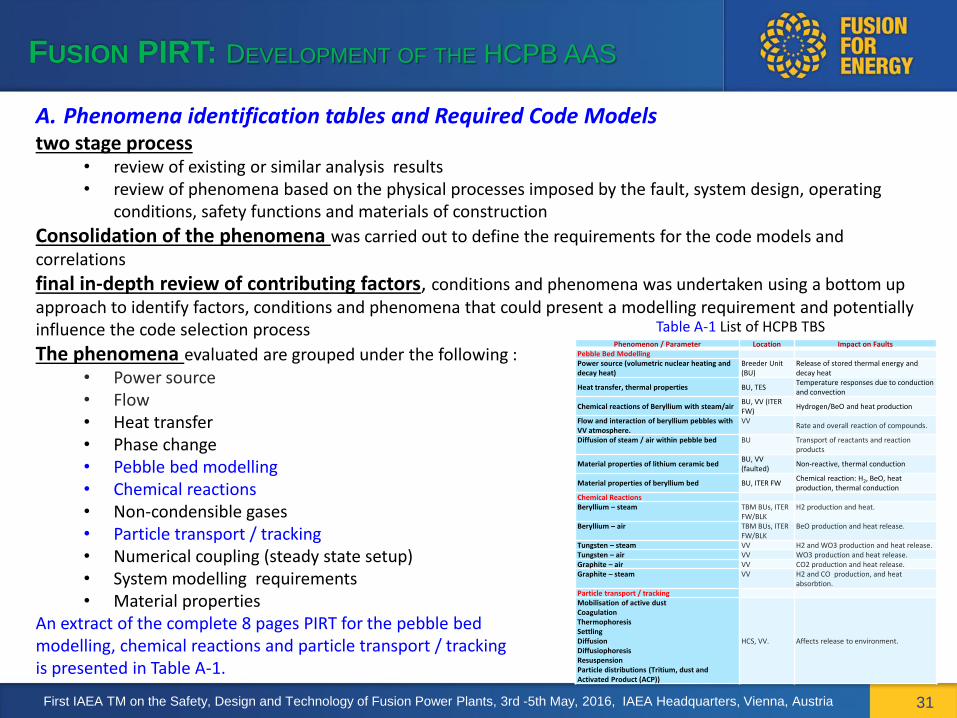
FUSION PIRT: DEVELOPMENT OF THE HCPB AAS
31
A. Phenomena identification tables and Required Code Models two stage process
• review of existing or similar analysis results • review of phenomena based on the physical processes imposed by the fault, system design, operating
conditions, safety functions and materials of construction
Consolidation of the phenomena was carried out to define the requirements for the code models and correlations
final in-depth review of contributing factors, conditions and phenomena was undertaken using a bottom up approach to identify factors, conditions and phenomena that could present a modelling requirement and potentially influence the code selection process
The phenomena evaluated are grouped under the following : • Power source • Flow • Heat transfer • Phase change • Pebble bed modelling • Chemical reactions • Non-condensible gases • Particle transport / tracking • Numerical coupling (steady state setup) • System modelling requirements • Material properties
An extract of the complete 8 pages PIRT for the pebble bed modelling, chemical reactions and particle transport / tracking is presented in Table A-1.
Table A-1 List of HCPB TBS Phenomena Phenomenon / Parameter Location Impact on Faults
Pebble Bed Modelling Power source (volumetric nuclear heating and decay heat)
Breeder Unit (BU)
Release of stored thermal energy and decay heat
Heat transfer, thermal properties BU, TES Temperature responses due to conduction and convection
Chemical reactions of Beryllium with steam/air BU, VV (ITER FW)
Hydrogen/BeO and heat production
Flow and interaction of beryllium pebbles with VV atmosphere.
VV Rate and overall reaction of compounds.
Diffusion of steam / air within pebble bed BU Transport of reactants and reaction products
Material properties of lithium ceramic bed BU, VV (faulted)
Non-reactive, thermal conduction
Material properties of beryllium bed BU, ITER FW Chemical reaction: H2, BeO, heat production, thermal conduction
Chemical Reactions Beryllium – steam TBM BUs, ITER
FW/BLK H2 production and heat.
Beryllium – air TBM BUs, ITER FW/BLK
BeO production and heat release.
Tungsten – steam VV H2 and WO3 production and heat release. Tungsten – air VV WO3 production and heat release. Graphite – air VV CO2 production and heat release. Graphite – steam VV H2 and CO production, and heat
absorbtion. Particle transport / tracking Mobilisation of active dust Coagulation Thermophoresis Settling Diffusion Diffusiophoresis Resuspension Particle distributions (Tritium, dust and Activated Product (ACP))
HCS, VV. Affects release to environment.
First IAEA TM on the Safety, Design and Technology of Fusion Power Plants, 3rd -5th May, 2016, IAEA Headquarters, Vienna, Austria

FUSION Code Assessment and Selection
32
Advantages of individual codes and versions • The premise for the MELCOR code selection process is that the later versions 1.8.6 and 2.1
developed by Sandia National Laboratory (SNL) should be the preferred options as these versions include additional new modelling features and improvements to existing models compared to earlier versions. However, the complete range of currently available fusion related code modifications has not been applied consistently to each of the MELCOR standard code versions.
• In terms of modelling capability the main contenders are fusion adapted MELCOR 1.8.5 and 1.8.6.
• Although the standard version of MELCOR 1.8.6 has advantages over MELCOR 1.8.5 (many COR related improvements, inclusion of flashing of superheated sources, treatment of MAEROS aerosol coefficients, film modelling in close proximity to the pool, more flexible application of thermal conductivity data and adjustments to the melt point for interacting materials), these are judged to have only limited impact on the modelling of the phenomena within the TBS.
• MELCOR 1.8.5 has the distinct advantage of providing a physical model for the representation of liquid PbLi and it response to accident scenarios.
• In terms of verification, the ‘pedigreed’ fusion-adapted MELCOR version 1.8.2 used for ITER safety studies has the advantage that a line-by-line review of the fusion-related updates has been performed. Although not as extensive as for v. 1.8.2, fusion-adapted MELCOR 1.8.5 and 1.8.6 have been subject to verification via comparison studies with standard (fission) MELCOR 1.8.5 and pedigreed MELCOR 1.8.2. Fusion-adapted MELCOR 1.8.5 has been used in other safety assessments involving PbLi .
• RELAP5-3D also has additional advantages in terms of heat transfer options that are relevant to the modelling of the HCLL TBS. It also includes the addition of the ATHENA multi-fluid package.
First IAEA TM on the Safety, Design and Technology of Fusion Power Plants, 3rd -5th May, 2016, IAEA Headquarters, Vienna, Austria
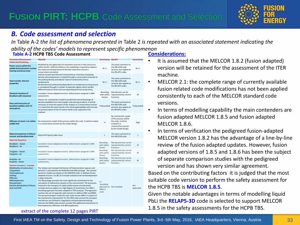
FUSION PIRT: HCPB Code Assessment and Selection
33
B. Code assessment and selection In Table A-2 the list of phenomena presented in Table 2 is repeated with an associated statement indicating the ability of the codes’ models to represent specific phenomenon Table A-2 HCPB TBS Code Assessment Considerations:
• It is assumed that the MELCOR 1.8.2 (fusion adapted) version will be retained for the assessment of the ITER machine.
• MELCOR 2.1: the complete range of currently available fusion related code modifications has not been applied consistently to each of the MELCOR standard code versions.
• In terms of modelling capability the main contenders are fusion adapted MELCOR 1.8.5 and fusion adapted MELCOR 1.8.6.
• In terms of verification the pedigreed fusion-adapted MELCOR version 1.8.2 has the advantage of a line-by-line review of the fusion adapted updates. However, fusion adapted versions of 1.8.5 and 1.8.6 has been the subject of separate comparison studies with the pedigreed version and has shown very similar agreement.
Based on the contributing factors it is judged that the most suitable code version to perform the safety assessment for the HCPB TBS is MELCOR 1.8.5. Given the notable advantages in terms of modelling liquid PbLi the RELAP5-3D code is selected to support MELCOR 1.8.5 in the safety assessments for the HCPB TBS.
Parameter/Phenomenon MELCOR Uncertainty RELAP5 Uncertainty Pebble Bed Modelling
Power source within the pebble bed (volumetric nuclear heating and decay heat)
Modelled by the application of volumetric sources in heat structures within the BU. Sufficient detail in the modelling is required to capture the maximum temperatures of the bed material to ensure a conservative calculation
M / L
The same comment on the MELCOR code versions also applies to the RELAP5 codes.
M / L
Heat transfer, thermal properties
Lithium ceramic bed thermal conductivity as a function of packing density and temperature is treated through a conservative estimate of the packing density and tabular input of conductivity versus temperature. Be bed thermal conductivity dependence on temperature and pressure is considered through a number of separate regions which exhibit different levels of strain and corresponding thermal conductivity.
M / L
The same comment on the MELCOR code versions also applies to the RELAP5 codes.
M / L
Chemical reactions of Beryllium with steam/air
Included in fusion adapted versions. Safety factors assigned in DBA assessments.
Bounding with safety
factors
Not dynamic can be represented by control functions
M
Flow and interaction of beryllium pebbles with VV atmosphere.
There is no mechanistic model to predict the overall discharge of beryllium pebbles from the breeder units during accidents. It will be necessary to treat this aspect of the analysis in a conservative manner. It is noted that the heat transfer from discharged pebbles will increase the pressurisation of the VV which needs to be captured in the analyses.
H (bounded)
The same comment on the MELCOR code versions also applies to the RELAP5 codes.
H (bounded)
Diffusion of steam / air within pebble bed
No mechanistic model of this process within the code. It will be treated in a conservative manner by the model design.
H
No mechanistic model of this process within the code. It will be treated in a conservative manner by the model design.
High
Material properties of lithium ceramic and beryllium beds
Material Property table input L The same comment on the MELCOR code
L
Chemical Reactions
Beryllium – steam Beryllium – air
Included in fusion adapted versions. Safety factors assigned in DBA assessments.
Bounding with safety factors
Not dynamic but can be represented by control functions.
M
Tungsten – steam Tungsten – air
Included in fusion adapted versions. Safety factors assigned in DBA assessments.
Bounding with safety factors
Not dynamic but can be represented by control functions.
M
Graphite –air Graphite - steam
Included in fusion adapted versions. Safety factors assigned in DBA assessments.
Bounding with safety factors
Not dynamic but can be represented by control functions.
M
Particle transport / tracking Mobilisation of active dust Coagulation Thermophoresis Settling Diffusion Diffusiophoresis Resuspension Particle distributions (Tritium, dust and ACP)
The release and transport behaviour of fission product vapours and aerosols is calculated by the RadioNuclide (RN) package . The aerosol dynamics models are based on the MAEROS code. In addition fusion adapted versions 1.8.2&1.8.5 include turbulent and inertial deposition in pipe networks. The RN package provides the most significant contribution to the calculation of radioactive releases to the environment. The processes involved in the transport of radionuclide masses are extremely complex and are subject to a high degree of uncertainty. For DBA a bounding approach has been adopted in ITER analyses. The approach involves the use of separate code versions to address DBA and BDBA. The aerosol transport model for each code version differ in respect of the mechanisms represented. For the DBA code version the transport mechanisms are limited to coagulation and gravitational settling, whereas the BDBA code version includes the additional mechanisms of thermophoresis, diffusion, and diffusiophoresis.
H – bounding approach to DBAs is used.
Not available. Not applicable
extract of the complete 12 pages PIRT
First IAEA TM on the Safety, Design and Technology of Fusion Power Plants, 3rd -5th May, 2016, IAEA Headquarters, Vienna, Austria

First IAEA TM on the Safety, Design and Technology of Fusion Power Plants, 3rd -5th May, 2016, IAEA Headquarters, Vienna, Austria
FUSION QUALIFICATION OF THE HCPB TBS MODELS
34
Test matrix HCPB TBS • Comparison with finite element (design) analyses (FEA) • Code-to code comparison • Sensitivity studies
TABLE A-3. HCLL TBS MODEL QUALIFICATION SUMMARY
# Case title Scenario and runs executed Code
Comparison with HCPB TBM design analyses
1 Full power steady-state
Steady-state TBM model analyses (MELCOR and RELAP5) compared to FEA results MELCOR RELAP5
2 Pulse TBM model analyses (MELCOR and RELAP5) of a 400 s power pulse MELCOR RELAP5
3 MARFE TBM model analyses (MELCOR and RELAP5) of a MARFE transient occurring from steady-state full power conditions compared to FEA results
MELCOR RELAP5
Analysis of HCPB TBS normal operation. Code to code comparison
4 TBS pulse TBS model analysis of a 400 s plasma power pulse. Model includes Port Plug, HCS, TBM and TES ancillary system models.
MELCOR RELAP5
Fault sequence test cases. Code to code comparison
5 Test transient S0
In-vessel FW LOCA close to end of 400 s plasma pulse followed by breach of the purge gas region of a BU to the VV.
MELCOR RELAP5
Sensitivity studies 6 S1 High beryllium temperature MELCOR
7 S2 High beryllium temperature and low beryllium conductivity MELCOR
8 S3 Reduced pebble bed friction MELCOR
9 S4 Few-node representation of BU purge gas regions MELCOR
10 S5 Combined high beryllium temperature and few-node representation MELCOR
Final step: MELCOR to RELAP-3D code-to-code comparison for 32h LOOP accident

FUSION BREEDING BLANKET UNCERTAINTY EVALUATION
35
Uncertainty Methods: Advantages An expert review of areas of uncertainty followed by the performance of sensitivity analyses has a number of significant advantages of flexibility, practicality, and improved understanding. The advantages of applied sensitivity analysis are listed below: • Flexibility: The use of sensitivity calculations allows the user to assess the influence of variations to specific
inputs/variables/models on the significant parameter results. • Practicality: It can take significant ‘real time’ to complete a single fault analysis transient. The majority of the
rigorous methods require a set number of calculations to achieve the required level of uncertainty in the calculated results.
• Improved understanding: The sensitivity calculations provide the analysts with a direct understanding of the contribution of variations to specific parameters. The approach allows the impact of individual uncertainties to be evaluated for different time periods within individual fault categories. Repeated sensitivity calculations investigating different parameters followed by a thorough review of the analysis results allows a description of the fault transients to be assembled with the influence of the significant uncertainties readily recognised.
Sources of Uncertainty Similar sources of uncertainty exist in the application of codes models to represent complex physical phenomena. These have been documented in various publications and papers worldwide.
1. Code models: The review of the code models and their application to the TBS fault study calculations has identified the strengths and weaknesses of the various code versions and has provided a recommendation for code selection. Code Validation and Verification: The conditions and phenomena experienced within the TBS fault scenarios are very specific to the ITER design and operation, consequently pertinent validation evidence is limited. However general TH processes are adequately covered by the codes. In addition, models which can contribute a large uncertainty to the results may be modified through user prescribed flags to achieve a conservative result.
First IAEA TM on the Safety, Design and Technology of Fusion Power Plants, 3rd -5th May, 2016, IAEA Headquarters, Vienna, Austria

FUSION BREEDING BLANKET UNCERTAINTY EVALUATION
36
Uncertainty analysis (continued) Sources of Uncertainty 2. System Model Representation include:
Nodalisation: The development of the model has to capture, in a slightly conservative manner, the physical processes involved within the fault scenarios and also to achieve this result. Model limitations/inaccuracies: In some circumstances the constraints of the code structure could impose restrictions on the model development. This is addressed during the model build. User effect: This can be addressed through seeking advice of experts in the field and reviewing previous analyses to gain an understanding of benefits and deficiencies in existing models developed by other users.
3. Plant operating parameters are usually set at conservative and bounding values to remove uncertainty from these sources in the calculations and introduce a level of conservatism.
4. Effect of Scale: The effects of scale are usually addressed by assessing the developed facility models against Integral Tests. There are no direct experimental test facilities which represent the ITER machine, however the MELCOR code has been extensively validated against PWR containment responses which has some applicability to the ITER Vacuum Vessel design. In addition the RELAP5 code has extensive application to pipework networks which have similar features to the highly engineered cooling channels in, for example the TBM First Wall (FW), cooling and stiffening plates. MELCOR and RELAP5 code-to-code comparisons will allow an assessment of the relative strengths of both codes.
At the initial stage of the qualification, a range of sensitivity studies have been executed (see Tables 5 and 6). These studies are to be augmented by a further series of sensitivity assessments to be performed during the fault analysis stages.
First IAEA TM on the Safety, Design and Technology of Fusion Power Plants, 3rd -5th May, 2016, IAEA Headquarters, Vienna, Austria
FUSION HCLL TBS Uncertainty PIRT
37
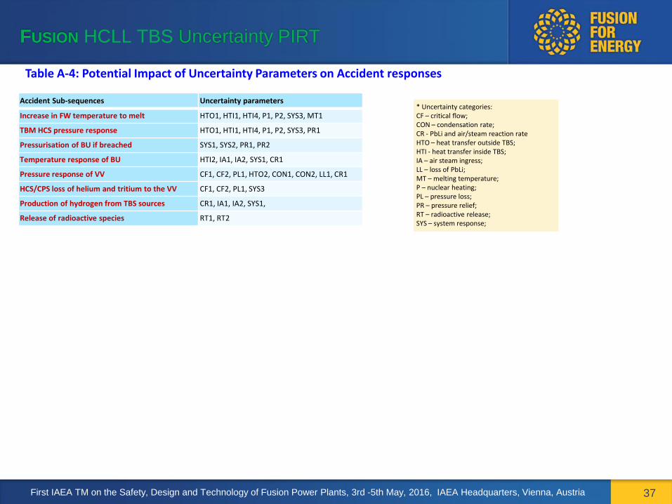
Table A-4: Potential Impact of Uncertainty Parameters on Accident responses
* Uncertainty categories: CF – critical flow; CON – condensation rate; CR - PbLi and air/steam reaction rate HTO – heat transfer outside TBS; HTI - heat transfer inside TBS; IA – air steam ingress; LL – loss of PbLi; MT – melting temperature; P – nuclear heating; PL – pressure loss; PR – pressure relief; RT – radioactive release; SYS – system response;
Accident Sub-sequences Uncertainty parameters
Increase in FW temperature to melt HTO1, HTI1, HTI4, P1, P2, SYS3, MT1
TBM HCS pressure response HTO1, HTI1, HTI4, P1, P2, SYS3, PR1
Pressurisation of BU if breached SYS1, SYS2, PR1, PR2
Temperature response of BU HTI2, IA1, IA2, SYS1, CR1
Pressure response of VV CF1, CF2, PL1, HTO2, CON1, CON2, LL1, CR1
HCS/CPS loss of helium and tritium to the VV CF1, CF2, PL1, SYS3
Production of hydrogen from TBS sources CR1, IA1, IA2, SYS1,
Release of radioactive species RT1, RT2
First IAEA TM on the Safety, Design and Technology of Fusion Power Plants, 3rd -5th May, 2016, IAEA Headquarters, Vienna, Austria