use of reinforced composite pipe (non-metallic...
TRANSCRIPT
Best Management Practice
Use of Reinforced Composite Pipe (Non-Metallic Pipelines) April/2017
2017-0005

2100, 350 – 7 Avenue S.W. Calgary, Alberta Canada T2P 3N9 Tel 403-267-1100 Fax 403-261-4622
1000, 275 Slater Street Ottawa, Ontario Canada K1P 5H9 Tel 613-288-2126 Fax 613- 236-4280
1004, 235 Water Street St. John’s, Newfoundland and Labrador Canada A1C 1B6 Tel 709-724-4200 Fax 709-724-4225
360B Harbour Road Victoria, British Columbia Canada V9A 3S1 Tel 778-265-3819 Fax 403-261-4622
The Canadian Association of Petroleum Producers (CAPP) represents companies, large
and small, that explore for, develop and produce natural gas and crude oil throughout Canada. CAPP’s
member companies produce about 85 per cent of Canada’s natural gas and crude oil. CAPP's associate
members provide a wide range of services that support the upstream crude oil and natural gas industry.
Together CAPP's members and associate members are an important part of a national industry with
revenues from crude oil and natural gas production of about $120 billion a year. CAPP’s mission, on
behalf of the Canadian upstream crude oil and natural gas industry, is to advocate for and enable
economic competitiveness and safe, environmentally and socially responsible performance.
DISCLAIMER
This publication was prepared for the Canadian Association of Petroleum Producers (CAPP) by J. Baron Project Services Inc. While it is believed that the information contained herein is reliable under the conditions and subject to the limitations set out, CAPP and J. Baron Project Services Inc do not guarantee its accuracy. The use of this report or any information contained will be at the user’s sole risk, regardless of any fault or negligence of J. Baron Project Services Inc, CAPP or its co-funders.

April 2017 Use of Reinforced Composite Pipe (Non-Metallic Pipelines) Page i
Overview
This guide is meant to provide increased awareness among designers, installers and users of non-metallic reinforced composite pipeline systems of some industry practices and lessons learned regarding reinforced composite pipelines used by the upstream oil and gas industry. This guide is not intended to be a detailed guide or design manual on the use of these materials for pipeline applications. Significant industry literature and documentation already exists on the design, manufacturing, installation and operation of reinforced composite pipelines. This information currently resides in pipe manufacturers’ manuals, and various industry standards and guides published by organizations such as ASTM International, American Petroleum Institute (API), American Water Works Association (AWWA) and International Organization for Standardization (ISO).
In Canada, the oil and natural gas industry pipeline code, CSA Z662-15, has a complete chapter dedicated to non-metallic pipeline systems (see Clause 13.0), which also includes specific requirements for reinforced composite pipelines (see Clause 13.1).
This guide intends to complement these existing industry documents and standards and not to replicate their contents.
Therefore, the main intention of this guide is to address the following:
Differences between conventional steel pipe and reinforced composite pipe; Lessons learned and recommended best practices as gathered from Canadian
industry experiences; Provide some guidance for designers, installers and users who may have
limited experience with reinforced composite pipelines.
Users should consult with the manufacturers of the pipe products in use, or being evaluated for use, for clarifications and suggestions regarding the best practices, considerations and applications of the materials in question.
In industry, repeated failures have been experienced and are often caused by poor practices in design and installation of reinforced composite pipelines, and also not following the advice and recommendations of experienced pipe manufacturers or their representatives, as available in their published design and installation manuals or through consultation.
In addition, pipeline operators should be aware of the applicable regulatory requirements for reinforced composite pipelines within the jurisdictions where they are operating. This guide is not intended to describe or define the application of local provincial or municipal government regulatory requirements that may apply to pipeline projects.
Note that this guide does not endorse any proprietary products or processes.

April 2017 Use of Reinforced Composite Pipe (Non-Metallic Pipelines)
Page i
Contents
Overview .............................................................................................................................. i
1 Project Scope ....................................................................................................... 1-1
1.1 Materials .................................................................................................. 1-1 1.2 Service Application .................................................................................. 1-1 1.3 Pipe Size................................................................................................... 1-1 1.4 Pressure Ratings ....................................................................................... 1-1
2 Review of Non-metallic Pipeline Failures ........................................................... 2-3
2.1 Summary .................................................................................................. 2-3 2.2 Common Incident Causes and Potential Solutions .................................. 2-5
2.2.1 Installation Related ...................................................................... 2-5
2.2.2 Internal Corrosion of Steel Risers ................................................ 2-8
2.2.3 External Corrosion of Steel Risers ............................................... 2-9
2.2.4 Third Party Damage ..................................................................... 2-9
3 Applications of Reinforced Composite Pipe...................................................... 3-11
3.1 General ................................................................................................... 3-11
3.1.1 Freestanding Pipe-in-Pipe .......................................................... 3-12
3.2 Material Selection Analysis ................................................................... 3-13 3.3 Sour Gas Applications ........................................................................... 3-14 3.4 Selection Guideline ................................................................................ 3-16
4 Design ................................................................................................................ 4-17
4.1 General ................................................................................................... 4-17 4.2 Pipeline Stress Analysis Considerations (Stick Pipe) ............................ 4-20 4.3 Pipeline Stress Analysis Considerations (Spoolable Pipe) .................... 4-21 4.4 Design Pressure ...................................................................................... 4-21 4.5 Design Temperature ............................................................................... 4-23
4.5.1 Thermal End Load ..................................................................... 4-24
4.6 Fluid Velocity ........................................................................................ 4-25
4.7 Pipeline Risers ....................................................................................... 4-25
4.7.1 Risers for Reinforced Composite Pipelines- General ................ 4-25
4.7.2 Risers for Stick Composite Pipe ................................................ 4-26
4.7.3 Spoolable Composite Pipeline Risers ........................................ 4-28
4.7.4 Spoolable Composite Pipeline Couplers .................................... 4-29
4.8 Fluid Hammer ........................................................................................ 4-30
4.9 Vacuum .................................................................................................. 4-30
5 Material Selection .............................................................................................. 5-31
5.1 Reinforced Composite Pipe Materials ................................................... 5-31
5.1.1 Stick Composite Pipe Products .................................................. 5-31
5.1.2 Spoolable Pipe Products ............................................................ 5-31
5.2 Material Selection for Metallic Couplers (Spoolable Pipe) ................... 5-33
5.3 Materials for Risers ................................................................................ 5-34

April 2017 Use of Reinforced Composite Pipe (Non-Metallic Pipelines)
Page ii
5.3.1 Reinforced Composite Pipe Risers ............................................ 5-34
5.3.2 Metallic Pipe Risers ................................................................... 5-34
6 Material Qualification ........................................................................................ 6-36
6.1 Design Stress/Pressure- Stick Pipe ........................................................ 6-36 6.2 Design Stress/Pressure- Spoolable Pipe................................................. 6-36 6.3 Additional Qualification Tests ............................................................... 6-37
7 Installation.......................................................................................................... 7-38
7.1 General ................................................................................................... 7-38
7.1.1 Spoolable Pipe Installations ....................................................... 7-38
7.1.2 Stick Pipe Installations ............................................................... 7-39
7.2 Pipe Transportation and Handling ......................................................... 7-40
7.2.1 Stick Pipe ................................................................................... 7-40
7.2.2 Spoolable Pipe ........................................................................... 7-42
7.3 Pipe Installation ..................................................................................... 7-43
7.3.1 Pipeline Trench Preparation ....................................................... 7-43
7.3.2 Road and River Crossings .......................................................... 7-45
7.4 Thrust Blocks and Anchors .................................................................... 7-46 7.5 Pipe-in-Pipe............................................................................................ 7-46 7.6 Metallic Tracer Wire .............................................................................. 7-48
8 Pipe Joining ........................................................................................................ 8-49
8.1 Stick Composite Pipe ............................................................................. 8-49
8.2 Spoolable Pipe ....................................................................................... 8-51
8.3 Inspection Test Plan ............................................................................... 8-53
9 Pressure Testing ................................................................................................. 9-53
9.1 New Construction .................................................................................. 9-53
9.2 Pressure Testing Repairs (Operating Pipelines) .................................... 9-54
10 Operation.......................................................................................................... 10-55
10.1 General ................................................................................................. 10-55
10.2 Pressure ................................................................................................ 10-55
10.3 Temperature ......................................................................................... 10-56
10.4 Pigging ................................................................................................. 10-56
10.5 Chemicals ............................................................................................. 10-57
10.6 Deactivation or Abandonment ............................................................. 10-57
11 Reinforced Composite Pipelines Repairs......................................................... 11-59
11.1 Stick Pipe Repairs ................................................................................ 11-59
11.2 Spoolable Pipe Repairs ........................................................................ 11-59
11.3 Excavation for Repairs ......................................................................... 11-59
12 Operations Monitoring ..................................................................................... 12-61
12.1 Leak Detection ..................................................................................... 12-61
12.2 Cathodic Protection (CP) ..................................................................... 12-61
12.3 Pressure Cycles .................................................................................... 12-61
April 2017 Use of Reinforced Composite Pipe (Non-Metallic Pipelines)
Page iii
12.4 Temperature Effects ............................................................................. 12-61
13 Operations, Maintenance and Integrity ............................................................ 13-63
13.1 Non-destructive Testing ....................................................................... 13-63 13.2 Pressure Testing ................................................................................... 13-63 13.3 Pipeline Risers ..................................................................................... 13-63 13.4 Pipe Cutouts ......................................................................................... 13-63 13.5 Integrity Management .......................................................................... 13-64
14 References ........................................................................................................ 14-66
A.1 Abbreviations and Acronyms ............................................................................ 14-1
B.1 Reinforced Composite Pipe Options- Temperature (T)/Diameter (D)/Pressure (P) Manufacturers Ratings Guideline ............................................................................ i
Figures
Figure 2-1 AER Regulated Normalized Pipeline Failure Frequency by Material Type ............. 2-3
Figure 2-2 Pressure Test Failures as a Percentage of Total Incidents ......................................... 2-4
Figure 2-3 Summary of Spoolable Pipe Failures by Cause ......................................................... 2-5
Figure 2-4 Summary of Stick Pipe Failures by Cause ................................................................. 2-5
Table 3-1 Typical Thermal Properties for Composite versus Steel Pipes ................................. 3-12
Table 3-2 Typical Values of Surface Roughness of Composite and Carbon Steel Pipes .......... 3-12
Table 3-3 Allowable Pressures and Services for Spoolable Composite Pipe (SCP) and Reinforced Thermoplastic Pipe (RTP) for Alberta............................................................ 3-15
Table 3-4 CSA Z662-15 Allowed Pressures and Services for Reinforced Composite Pipelines in Canada ........................................................................................................... 3-16
Table 4-1 Stick Composite Pipe Typical Physical Properties Comparison to Carbon Steel Pipe1
........................................................................................................................................... 4-19
Table 4-2 CSA Z662-15 Service Fluid Factors (Ffluid) .............................................................. 4-22
Figure 4-1 Pipeline Riser showing use of Sand Bagging for Support and Thrust Blocking. Composite Riser Extends above Grade to Flange Transition to Steel Piping ................... 4-28
Figure 4-2 Spoolable Pipe Metallic Coupler Installation .......................................................... 4-30
(Photograph courtesy of FlexSteel Pipeline Technologies Ltd.) ............................................... 4-30
Figure 7-1 Typical Spoolable Reinforced Thermoplastic Pipe (RTP) Plough-In Installation Method ............................................................................................................................... 7-40
Figure 7-2 Typical Wooden Cradle Supports and Tie Down for Large Diameter Pipe Transport ........................................................................................................................................... 7-42
Figure 7-3 Spoolable Pipe Transport on Reel Trailer ................................................................ 7-43
Figure 7-4 Large Diameter Rigid Composite Pipe; Placement of Select Fill Bedding. ............ 7-45
Figure 7-5 Spoolable Composite Pipe (SCP) - Unreeling Pipe for Placement in Pipeline Trench. ............................................................................................................................... 7-48
Figure 8-1 Provision of Shelters for Joining Composite Pipe ................................................... 8-51
Figure 8-2 Metallic Coupler Joining Sections of Spoolable Pipe .............................................. 8-52

April 2017 Use of Reinforced Composite Pipe (Non-Metallic Pipelines)
Page iv
Tables
Table 3-1 Typical Thermal Properties for Composite versus Steel Pipes ................................. 3-12
Table 3-2 Typical Values of Surface Roughness of Composite and Carbon Steel Pipes .......... 3-12
Table 3-3 Allowable Pressures and Services for Spoolable Composite Pipe (SCP) and Reinforced Thermoplastic Pipe (RTP) for Alberta............................................................ 3-15
Table 3-4 CSA Z662-15 Allowed Pressures and Services for Reinforced Composite Pipelines in Canada ............................................................................................................................... 3-16
Table 4-1 Stick Composite Pipe Typical Physical Properties Comparison to Carbon Steel Pipe1... …………………………………………………………………………………………….4-19
Table 4-2 CSA Z662-15 Service Fluid Factors (Ffluid) .............................................................. 4-22

April 2017 Use of Reinforced Composite Pipe (Non-Metallic Pipelines) Page 1-1
1 Project Scope
The scope of this document is to provide some best practices for users of reinforced composite pipeline materials. The materials discussed within this guide include both standard individual length rigid pipe (or stick pipe) and flexible reinforced composite pipes (or spoolable pipe).
1.1 Materials
The use of the term reinforced composite pipe may mean different things to different people as the term is often applied to many different types of non-metallic pipe. For the purpose of this document, rigid individual length reinforced composite pipe will be referred to as “stick pipe” while spoolable reinforced composite pipe will be referred to as “spoolable pipe.”
Stick pipe generally refers to a fiberglass filament wound rigid pipe material with an epoxy-based matrix binder.
Spoolable pipe generally refers to two general categories:
Spoolable composite pipe (SCP) and Reinforced thermoplastic pipe (RTP).
SCP products use a bonded glass outer reinforcement and thermoplastic inner liner. RTP products use an un-bonded outer reinforcement, such as glass fibre, steel strip/braided cable or polymer fibre tape and thermoplastic inner liner.
1.2 Service Application
The service applications discussed are for production pipeline systems used by the upstream oil and natural gas industry, located in Western Canada. These systems include oil well multiphase flow lines, natural gas well gathering pipelines, oilfield water disposal pipelines, and oilfield water injection pipelines. Other specialized applications may also be relevant, such as large-diameter pipelines for hot water supply, underground firewater distribution systems within plant sites or between base processing plants and remote mining sites.
1.3 Pipe Size
Pipe sizes for stick pipe can vary from NPS 2” to NPS 48”—or larger depending on the product manufacturer.
Spoolable pipe diameters available are NPS 2” to NPS 8” and are based on the product manufacturer capabilities. Smaller diameter pipe may be available by special order. Note that each product may have a different actual outside diameter, as spoolable pipe does not have an actual standardized outside diameter.
1.4 Pressure Ratings
Pipe pressure ratings for stick pipe will vary by diameter and wall thickness. Typically, smaller diameter pipes are available with higher pressure ratings up to approximately 20 MPa while larger diameter pipe, such as NPS 36”, are available at much lower pressure ratings of 1 to 2 MPa.

April 2017 Use of Reinforced Composite Pipe (Non-Metallic Pipelines) Page 1-2
For the various spoolable pipe products, different pressure-rated pipe products are available, up to approximately 20 MPa. The pressure rating available will depend on the product and pipe diameter involved, as not all spoolable pipe products are rated for the same pressure. In some cases, pipe manufacturers may be capable of producing special-sized or pressure-rated pipe that may not be listed in their standard product literature.

April 2017 Use of Reinforced Composite Pipe (Non-Metallic Pipelines) 2-3
2 Review of Non-metallic Pipeline Failures
2.1 Summary
In 2007, an analysis of pipeline failure statistics was performed and presented at a pipeline symposium held in Banff, Alberta. The analysis showed a relatively high incident rate with reinforced composite pipelines. The analysis was updated in 2015 to reflect the incident data from 2002 to 2014. Stick pipe and spoolable pipe incidents remain at a much higher incident rate than for steel pipe. In addition, a large percentage of pressure test failures have been recorded.
Figure 2-1 provides a summary of the incident frequencies determined by material type (excludes pressure test failures). Figure 2-2 provides a summary of the pressure test failures as a percentage of total incidents.
Figure 2-1 AER Regulated Normalized Pipeline Failure Frequency by Material Type (Excludes Pressure Test Failures)

April 2017 Use of Reinforced Composite Pipe (Non-Metallic Pipelines) 2-4
Figure 2-2 Pressure Test Failures as a Percentage of Total Incidents
Figures 2-3 and 2-4 provide a summary of reinforced composite pipeline failures in Alberta by cause from 2002 to 2014 (excludes pressure test failures). The data reveals some of the more common and recurring stated causes of failures, including:
Damage resulting from installation practices; Corrosion of associated steel pipe risers and fittings; Damage by others (third-party damage); Mechanical failures of valves or fittings; Miscellaneous/pipe failure.

April 2017 Use of Reinforced Composite Pipe (Non-Metallic Pipelines) 2-5
Figure 2-3 Summary of Spoolable Pipe Failures by Cause (Top 80% Contributing Factors, Excludes Pressure Test Failures)
Figure 2-4 Summary of Stick Pipe Failures by Cause (Top 80% Contributing Factors, Excludes Pressure Test Failures)
2.2 Common Incident Causes and Potential Solutions
2.2.1 Installation Related
Installation-related damage leading to pipe failures can result from several causes. Most often, installation damage is unintentional and results from trying to install reinforced composite pipelines using similar techniques and installations to those used for steel pipelines. The reinforced composite pipe installation requirements generally do not differ a lot from good installation practices for steel pipelines in terms of providing good quality pipeline trench and soil properties such as providing pipe support and having low rock content. However, reinforced composite pipe is more fragile than steel pipe and is more likely to fail prematurely

April 2017 Use of Reinforced Composite Pipe (Non-Metallic Pipelines) 2-6
than steel due to installation-related deficiencies, such as poor soil support, inappropriate anchoring, pipe impacts from frozen soil lumps or rocks and improper backfilling practices.
In some cases, installation damage may be identified during the preliminary pressure test and repaired. In other cases, damage may take much longer to develop into a failure during operation. Two primary forms of damage that may take years to cause failure include pipe abrasion (caused by sharp objects, such as sharp rocks rubbing against the pipe) and pipe impact (caused by dropping heavy items such as frozen backfill or large rocks onto the pipe during backfilling). Damage to the outer resin surface can lead to water ingress into the pipe wall resin/glass matrix and cause loss of strength and failure over time.
A primary damage mechanism is the lack of underground pipe support. If the soil support to the pipe is not adequate or uniform, reinforced composite pipe could be damaged due to uneven pipe settlement into the trench bottom. This may lead to the development of excessive axial or shear stresses in the pipe body or at connections. Such soil instability can be created during construction, if the soil is over-excavated at the base of the riser pipe-ends, resulting in inadequate soil support to the riser pipe. Therefore, special attention must be paid to construction of risers to ensure proper support and protection of the pipe.
Note: Where the reinforced composite pipeline is connected to above-ground steel headers or wellsite piping, the steel piping should be supported independently of the pipeline risers. Anchoring to an above-ground steel piping system utilized for supporting the pipeline risers is not recommended.
In some cases, differential movement between well anchored riser piping and the connected pipeline has led to stress failure of fittings or pipe body at or near to the riser. Therefore, such below-ground connections at risers must be designed and installed with due care.
For spoolable pipe risers, an underground structural steel support is often used to secure the riser; however, this type of support structure is not intended to support above-ground steel piping. The transition from the exit of the riser chute to the trench bottom should be on undisturbed ground that may require use of a riser extension support from the chute base to the undisturbed ground.
Another area of concern for stick pipe is pipe joint integrity. As a general rule, pipe joints are made from either threaded mechanical connections on smaller diameter stick pipe (<12 inch) or adhesive bonded bell and spigot on larger diameter pipe. In some cases, for larger diameter stick pipe, a butt and wrap joint using manual application of glass matt and resin is employed.
Currently there is no proven technology for non-destructive examination (NDE) of these joints before placing them into service. Therefore, the qualifications and competencies of joining personnel—along with strict adherence to the qualified joining procedure—should be required and is a key success factor. This is a challenging area to manage for pipeline construction projects, especially for

April 2017 Use of Reinforced Composite Pipe (Non-Metallic Pipelines) 2-7
installers whose pipeline installation experience is based primarily on steel pipelines.
Similarly, each spoolable pipe product has different joining coupler designs, which are mainly mechanical in nature and rely on strict adherence to installation procedures and qualified personnel. In some cases, manufacturers allow field installations of their proprietary connections by construction contractors.
The manufacturers of reinforced composite pipe products provide installers with training and certification. For both stick pipe and spoolable pipe projects, end users should ensure the installation personnel on projects have a valid training certificate as currently specified by CSA Z662-2015.
With spoolable pipes, a great deal of care should be taken to not twist or over-torque the pipe body during placement. This is especially important during wintertime construction when the inner liner material is less ductile and more brittle than when installed at warmer temperatures. Over-torquing could cause cracking or microcracking to develop in the outer reinforcement structure or inner liner that may result in failure under pressure during pressure testing or later while in service.
Example of Over-Torque Damage: Over-torque damage could result from attempting to stretch or force the reinforced composite pipe (with ends that already have flanges installed on them) to mate-up to the fixed risers or piping in situations where the above-ground risers or piping are installed before constructing the pipeline.
With spoolable pipe, kinking or damage to the glass winding pattern spacing can occur during installation and requires careful unreeling and vigilance during construction. This is especially important if heat is applied to the pipe reel during winter construction. Non-uniform heating on the reel must be avoided as it may cause kinks to form where the pipe becomes more pliable in heated areas but remains much stiffer in colder areas of the reel.
Therefore, any heating of spoolable pipe reels must be done carefully and in accordance with the manufacturer’s procedure. Caution should be exercised to not overheat the pipe above its specified maximum temperature limit.
Where spoolable pipes or reinforced composite pipes are installed as a free-standing pipe-in-pipe through an existing steel carrier pipe, support of the spoolable pipe where it enters and exits that steel pipe is of primary importance. The steel carrier pipe will normally be installed in a solid and settled area of ground. However, the area where the composite pipe exits the steel carrier pipe is subject to new and varying soil settling that could lead to a failure at the entry/exit areas of the carrier pipe. Furthermore, any intermediate bell-hole excavation locations that connect two adjacent pull sections through existing carrier pipe may cause differential soil settling and excessive shear stress to develop within the spoolable pipeline.
For installation of reinforced composite pipe inside existing pipe, either pull-in or push-in methods are used. It is critical to prepare an installation procedure that
April 2017 Use of Reinforced Composite Pipe (Non-Metallic Pipelines) 2-8
includes maximum tensile or compressive loading of the pipe. Exceeding the maximum specified load can result in pipe damage. The condition of the outer conduit pipe must also be assessed, typically by pigging, to size the internal diameter and detect any other features such as fittings or dents that may lead to damage during installation.
The need for internal and external corrosion protection for metallic joining couplers used for spoolable pipes should also be provided, based on the corrosiveness of the service fluid and general soil conditions. Application of protective coating and cathodic protection (CP) must also be considered.
2.2.2 Internal Corrosion of Steel Risers
In some cases, the use of a carbon steel pipe riser for reinforced composite pipelines is preferred by some end users. The use of steel pipe is usually to provide increased strength, damage resistance or fire resistance for the pipe riser section.
Since reinforced composite pipelines are often installed to transport highly corrosive service fluid, internal corrosion of the steel pipe riser should be considered a threat and mitigated. As the cause of failure data in Figures 2-3 and 2-4 illustrates, internal corrosion of steel piping that is associated with reinforced composite pipelines is one of the leading causes of failure.
In some cases, chemical inhibition may be a consideration to protect the steel riser piping, but the possible effects of the chemical on the reinforced composite pipeline material must also be considered.
Most often, internal corrosion mitigation is accomplished by using internal plastic coatings that are shop-applied beforehand. At times, specialty coated and welded insert fittings are used to fabricate risers using coated pipe sections.
A couple of factors to consider for use of plastic coatings with risers are the diameter and design of the riser. The use of NPS 2 diameter pipe is not recommended since generally this is too small to successfully apply internal coating.
The use of an appropriate internal coating product, combined with a quality application by an experienced coating application expert, is highly recommended. There are several internal pipe coating application contractors available within the industry who specialize in this type of coating application and should be utilized for riser coatings. Industrial coating manufacturers should also be consulted for their recommendations of suitable internal coating materials and applicators. Using a coating with adequate temperature and chemical resistance is also of key consideration. Epoxy-based coatings are most often specified in typical thickness range of 300-400 microns (12-16 mils).
Internally coated steel pipe risers should also be designed with suitable flanges or fittings that provide internal access for both weld area grinding and the coating application, as coatings may fail prematurely if weld beads are left rough or if weld splatter exists. Where access for weld grinding in pipe spools is not practical, the use of alternate welding processes that develop a smoother internal weld bead, such

April 2017 Use of Reinforced Composite Pipe (Non-Metallic Pipelines) 2-9
as MIG, should be considered. NACE SP0178 provides information on preparing weld surfaces for internal coating application.
Diameter differences between reinforced composite piping and the riser piping (particularly when the riser piping diameter is smaller) should be evaluated in the coating selection step with regard to the coating’s erosion resistance properties.
Where pipelines require pigging, the effects of diameter variances between pipeline and riser piping should be considered. Reinforced composite pipe products have unique internal diameters and are not standardized to steel nominal diameters so suitable diameter pigs should be selected.
Where possible, gradual diameter changes should be used as more aggressive changes may lead to premature coating failure (i.e. NPS 4 piping reduced to a 2" valve assembly). Furthermore, flanged connections versus welded connections should be considered for ease of coating smaller pipe sections and grinding weld areas for surface preparation. Cost is a factor to be considered here, as flanged connections are normally more expensive than welded connections.
The field application of internal coatings is not normally recommended due to the inability to adequately clean the steel pipe and apply uniform coatings under typically adverse field conditions. Therefore, steel pipe riser internal coating applications should be performed in a specialized coatings application shop.
It is also common to install reinforced composite pipe risers and to transition to steel pipe just above ground level with a flange. This practice is discussed in more detail in the design and installation sections 4.0 and 7.0 of this guide.
In some cases, corrosion-resistant alloy (CRA) piping—such as stainless steel alloys—has been used for risers; however, an appropriate alloy material that is suitable for the service fluid and operating temperature should be carefully selected. The alloy selection and connecting method between the alloy riser piping and the reinforced composite pipe should be discussed with the reinforced composite pipe manufacturer.
2.2.3 External Corrosion of Steel Risers
External corrosion of steel risers is also identified as a cause of failure. Where steel risers are employed in conjunction with reinforced composite pipelines, suitable external coatings such as liquid epoxy, shrink sleeves or tape wraps rated for the current and future service temperatures should be applied. To supplement the protective coating, spot CP should also be installed—usually with a sacrificial anode. It is recommended that the sacrificial anodes have above ground test leads to allow for anode life monitoring.
2.2.4 Third Party Damage
Damage by third parties is identified as a cause of service failures for reinforced composite pipelines. In some cases, this is a result of a lack of knowledge regarding the accurate location of underground pipelines or not following industry-recognized ground disturbance procedures.

April 2017 Use of Reinforced Composite Pipe (Non-Metallic Pipelines) 2-10
It is important—and a CSA Z662-15 pipeline code requirement—that all reinforced composite pipelines be installed with a suitable tracer wire to allow accurate use of pipeline location equipment. Tracer wire may not be required for some spoolable pipes that utilize either metallic wire or strip reinforcements, however the manufacturer should be consulted for clarification on this requirement.
In older oil fields, pipelines may have been installed without tracer wire. In such cases, careful analysis and caution should be exercised—using information such as drawings or installation files—to best determine pipe location. Again, proper ground disturbance that avoids the use of mechanical excavation near buried facilities can help minimize this risk. Above-ground pipeline markers are also required and recommended to help increase awareness of underground pipelines and to help locate pipelines.
In cases where the pipe location is not accurately known, there may be no choice but to perform careful hand or hydro-vacuum excavation to locate the pipeline. Audible sound probes may also be considered to locate the pipeline. Use of steel probes pushed through the soil to locate pipe should be done very carefully as these can damage reinforced composite pipe if they have sharp-pointed ends or are driven into the pipe wall with excessive force.

April 2017 Use of Reinforced Composite Pipe (Non-Metallic Pipelines) 3-11
3 Applications of Reinforced Composite Pipe
3.1 General
Reinforced composite pipe is used by the oil and natural gas production industry for various pipeline services. Typically, it is used for more highly corrosive fluid applications. Services include the following applications:
Oil, natural gas, water multiphase fluid pipelines; Natural gas gathering production pipelines and fuel gas supply pipelines; Oilfield water pipelines (produced waters and fresh water).
In most cases, reinforced composite pipelines are initially considered and installed to provide longer-term operating benefits to the pipeline operator. Initial material costs will vary given the prevailing market conditions and price fluctuations for both steel and composite materials. In some cases, the installed cost may be lower compared to steel pipelines but relative cost usually depends on the pipe product and the pipeline installation specifics.
Regardless of the initial pipe material and installation costs, the potential for reduced operating cost is a primary consideration in the use of reinforced composite pipe. Where possible, economic comparisons between reinforced composite pipe and carbon steel pipe should be based on total life cycle costs that consider the initial capital costs and the operating and maintenance costs over the life of the pipeline. Consideration should also be made on how to monitor the pipeline integrity over its life and the associated costs.
Internal corrosion resistance to corrosive agents within the service fluid, such as wet carbon dioxide and sodium chloride, is one of the primary benefits of reinforced composite pipe material and an important means of reducing operating costs. Steel oil and natural gas production industry pipelines generally require various measures to control internal corrosion, such as the injection of a chemical corrosion inhibitor on a continuous or batch-basis, internal thin film organic coatings and the use of pigs to remove stagnant water and debris. Such mitigation methods represent additional operating costs that will last over the life of the pipeline.
In some cases, chemical corrosion inhibition treatments are not required, but in other cases, due to the presence of remaining steel facilities such as risers or inter-connected steel pipelines, internal corrosion mitigation is still required. See Sections 4.1, 5.1 and 10.5 for further information on chemical compatibility.
In some cases, reinforced composite pipe is installed to provide increased resistance to the buildup of deposits such as paraffin waxes or scales on the pipe internal surface that can reduce flow and increase pressure drop. This benefit is derived from the smoother pipe surface, the lower thermal conductivity, and higher specific heat capacity of reinforced composite pipe compared to steel pipe. Table 3-1 provides typical thermal properties of reinforced composite versus carbon steel pipes.

April 2017 Use of Reinforced Composite Pipe (Non-Metallic Pipelines) 3-12
Table 3-1 Typical Thermal Properties for Composite versus Steel Pipes
Material Thermal Conductivity, W/mK
Specific Heat, J/kg K
Steel Pipe 50 450
Composite Pipe 0.4 1670
Internal corrosion of carbon steel pipe in water services can lead to the significant buildup of scales or fouling deposits. Such buildup may have a significant effect on pump pressure drop performance through the pipeline and lead to increased power consumption or decreased injection-well performance.
The internal surface of reinforced composite pipe is only slightly smoother than new steel pipe; however, the surface finish of new steel can degrade and become much rougher over time due to corrosion and/or scale buildup.
Table 3-2 provides some of the typical published values of surface roughness and the Hazen Williams flow coefficient for reinforced composite pipes compared to carbon steel pipe. The typical values given in Table 3-2 are for general information only. For surface roughness values for individual pipe products the pipe manufacturer’s product specifications should be consulted and their specified values used for individual project evaluations.
Table 3-2 Typical Values of Surface Roughness of Composite and Carbon Steel Pipes
Material Surface Roughness, mm Hazen Williams Flow Factors
Steel Pipe, new 0.040 130-140
Steel Pipe, lightly rusted 0.400 100
Steel Pipe, very rusted or scaled
3.400 60-80
Composite Pipe 0.005 150
3.1.1 Freestanding Pipe-in-Pipe
Reinforced composite pipe is also commonly installed as a smaller diameter pipeline inside an existing steel carrier pipeline that has failed or is expected to be in poor condition due to corrosion. This method of pipe installation is also
April 2017 Use of Reinforced Composite Pipe (Non-Metallic Pipelines) 3-13
referred to as slip-lining or use of a free-standing pipe-in-pipe. Use of this method may be less costly than conventional replacement of the pipeline or running an internal inspection smart pig (ILI).
This approach can also offer environmental advantages given the smaller footprint it creates as excavations are only required for access at the ends of pipeline sections where the reinforced composite pipe is inserted or exits the carrier pipe. Also, the existing pipeline right-of-way can be utilized and no additional right-of-way is required, thereby further minimizing landowner impact.
However, in the event of the reinforced composite pipe failing inside a damaged carrier pipe, knowledge of the slope of the land and/or locations of discontinuities in the carrier pipe are important factors to allow determination of where any fluid may come to surface. Further, the removal of the reinforced composite pipeline and spilled product within the carrier pipe may become a difficult task.
The areas where the carrier pipe is removed to allow installation of the inner pipe should be located in suitable areas that are less sensitive and away from streams and bodies of water, etc. To provide further containment, a secondary sleeve may be installed over the connection areas. This allows monitoring and flow control to be more focused at the end points of the pipeline.
Therefore, a review of bell-hole locations and any known sections of the carrier pipe that may have been permanently removed for installation of the composite pipe should be documented and readily available in the event of a failure.. The carrier pipe should be electrically bonded for pipe location tracing.
Where the carrier pipe is continuous, the installation of vents on the carrier pipe may also be considered at various locations.
Use of GPS coordinates is recommended to keep track of the bell-holes or missing sections of carrier pipe.
3.2 Material Selection Analysis
The final selection of suitable pipeline materials requires extensive analysis on a project-by-project basis and is well beyond the scope of this document. A thorough understanding of the intended service conditions, including the expected normal operating conditions and also any upset conditions that could occur, is required. Future field development plans also need to be considered as are any planned changes in service conditions, such as increases in temperature, static pressure, cyclic pressure, production rates, or hydrogen sulphide (H2S) levels that could change or occur in the future development of the field. These new conditions may not be suitable or may present increased risk for the use of reinforced composite pipeline materials. Design life is another critical parameter in determining the strength and type of material selected. More detailed coverage of the design aspects of using reinforced composite pipe for pipelines is in Section 4.
Some key conditions that should be understood when selecting pipeline materials include:

April 2017 Use of Reinforced Composite Pipe (Non-Metallic Pipelines) 3-14
Steady-state conditions:
Service fluid compositions, such as corrosive products, sand, wax, etc.; Operating flow rates; Operating pressure range including the amplitude and frequency of pressure
cycles; Operating temperatures; Pumping conditions including pump start/stop parameters; Pump pulsation control.
Upset operating conditions
Transient flow; Start-up/shut down characteristics (e.g. valve closure timing, electrical grid
power bumps); Pigging requirements (due to liquid or wax buildup); Availability and reliability of power source for cathodic protection system.
Where routine high-cyclic pressure operation is possible for the pipeline in question, this aspect should be carefully considered and discussed with the pipe manufacturer prior to material selection and accounted for in the pipeline design as specified by CSA Z662-15.
CSA Z662-15 specifies service to be cyclic when the operating pressure regularly cycles more than 20 per cent of the pipeline maximum design pressure.
Associated operating conditions, such as pigging requirements, hot-oiling, and the use of additive chemicals or well stimulation chemical exposures must also be understood and included in the materials selection.
The pipeline terrain conditions must also be well understood as described in Section 4.
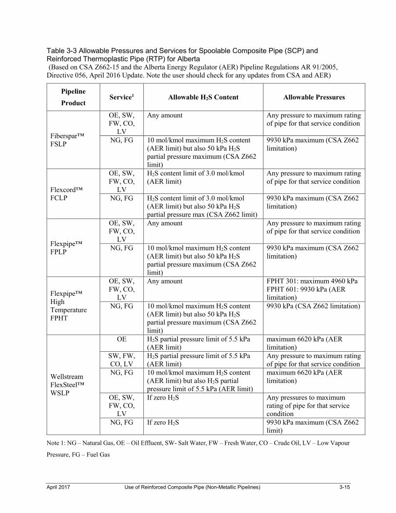
3.3 Sour Gas Applications
For reinforced composite pipe products that utilize metallic reinforcements, the suitability for sour service fluids, including natural gas, oil and water, should be reviewed by end users in consultation with the manufacturer. This is required due to the permeation of H2S and other gases through the liner layer and contact with the metallic reinforcement layer and the potential for corrosion or sulphide stress cracking (SSC) of the reinforcement.
For pipelines located in Alberta, the Alberta Energy Regulator (AER) Directive 056 limits various non-metallic pipe products to allowable H2S and pressures. See Table 3-3.
Canadian Standard Association (CSA) standard Z662-15 for oil and natural gas pipelines in Canada specifies limits for pressure for some services fluids and H2S limits for non-metallic pipe products. See Table 3-4.
Metallic components installed in sour service pipelines are required to meet CSA Z662-15, Clause 16.
April 2017 Use of Reinforced Composite Pipe (Non-Metallic Pipelines) 3-15
Table 3-3 Allowable Pressures and Services for Spoolable Composite Pipe (SCP) and Reinforced Thermoplastic Pipe (RTP) for Alberta (Based on CSA Z662-15 and the Alberta Energy Regulator (AER) Pipeline Regulations AR 91/2005, Directive 056, April 2016 Update. Note the user should check for any updates from CSA and AER)
Pipeline
Product Service1 Allowable H2S Content Allowable Pressures
Fiberspar™ FSLP
OE, SW, FW, CO,
LV
Any amount Any pressure to maximum rating of pipe for that service condition
NG, FG 10 mol/kmol maximum H2S content (AER limit) but also 50 kPa H2S partial pressure maximum (CSA Z662 limit)
9930 kPa maximum (CSA Z662 limitation)
Flexcord™ FCLP
OE, SW, FW, CO,
LV
H2S content limit of 3.0 mol/kmol (AER limit)
Any pressure to maximum rating of pipe for that service condition
NG, FG H2S content limit of 3.0 mol/kmol (AER limit) but also 50 kPa H2S partial pressure max (CSA Z662 limit)
9930 kPa maximum (CSA Z662 limitation)
Flexpipe™ FPLP
OE, SW, FW, CO,
LV
Any amount Any pressure to maximum rating of pipe for that service condition
NG, FG 10 mol/kmol maximum H2S content (AER limit) but also 50 kPa H2S partial pressure maximum (CSA Z662 limit)
9930 kPa maximum (CSA Z662 limitation)
Flexpipe™ High Temperature FPHT
OE, SW, FW, CO,
LV
Any amount FPHT 301: maximum 4960 kPa FPHT 601: 9930 kPa (AER limitation)
NG, FG 10 mol/kmol maximum H2S content (AER limit) but also 50 kPa H2S partial pressure maximum (CSA Z662 limit)
9930 kPa (CSA Z662 limitation)
Wellstream FlexSteel™ WSLP
OE H2S partial pressure limit of 5.5 kPa (AER limit)
maximum 6620 kPa (AER limitation)
SW, FW, CO, LV
H2S partial pressure limit of 5.5 kPa (AER limit)
Any pressure to maximum rating of pipe for that service condition
NG, FG 10 mol/kmol maximum H2S content (AER limit) but also H2S partial pressure limit of 5.5 kPa (AER limit)
maximum 6620 kPa (AER limitation)
OE, SW, FW, CO,
LV
If zero H2S Any pressures to maximum rating of pipe for that service condition
NG, FG If zero H2S 9930 kPa maximum (CSA Z662 limit)
Note 1: NG – Natural Gas, OE – Oil Effluent, SW- Salt Water, FW – Fresh Water, CO – Crude Oil, LV – Low Vapour
Pressure, FG – Fuel Gas

April 2017 Use of Reinforced Composite Pipe (Non-Metallic Pipelines) 3-16
Table 3-4 CSA Z662-15 Allowed Pressures and Services for Reinforced Composite Pipelines in Canada
Pipeline Type Service1 Allowable H2S Content Allowable Pressures
Reinforced Composite Pipe
(Stick, SCP, RTP)
OE, SW, FW, CO, LV
Any amount Any pressure to maximum rating of pipe for that service condition
NG, FG 50 kPa H2S partial pressure maximum based on pipeline
design pressure.
9930 kPa maximum design pressure
Note 1: NG – Natural Gas, OE – Oil Effluent, SW- Salt Water, FW – Fresh Water, CO – Crude Oil, LV –
Low Vapour Pressure, FG – Fuel Gas
3.4 Selection Guideline
A recommended selection guideline table is provided in Appendix B for information only and is based on manufacturers’ published product specifications.
For the selection of reinforced composite pipes in particular, strict attention should be given to the combination of service pressure and temperature including upset operating conditions. Each pipeline environment includes a unique combination of temperature, pressure, stress and chemical factors and should also be considered. The combined effects of these factors on the reinforced composite pipe should be determined based on the manufacturer’s recommendations—and additional testing if required—in the selection of a suitable material.
Reinforced composite pipe manufacturers usually qualify their products based on long-term tests using water at various stress levels and temperature conditions. However, prudent pipeline design may warrant that some de-rating factors be applied as determined on a project-by-project basis by the project design engineer. Therefore the service conditions, installation conditions and design factors should be discussed and determined by the designer for each situation. This should be done in conjunction with input from the pipe manufacturer’s technical staff..
CSA Z662-15 provides the minimum service fluid design factors that are specified to determine the pipeline design pressure (refer to Table 4-2 in Section 4 of this guide for an overview of the minimum service fluid factors).

April 2017 Use of Reinforced Composite Pipe (Non-Metallic Pipelines) 4-17
4 Design
4.1 General
As stated in Section 3, reinforced composite pipeline design requires a thorough understanding of the intended service conditions on a per-project basis that includes the expected normal operating conditions, future operating conditions, and any associated or upset operating conditions. Projects undertaken without due care and awareness of the differences in material properties compared to steel are not likely to succeed. Therefore, short- and long-term success requires extra attention to various aspects at the pipeline design stage, several of which are highlighted in this section.
Success with reinforced composite pipelines usually involves aspects of design that go beyond a simple review of pipe pressure rating to include the following:
Selection of a suitable pipe product; Assessment of soil conditions to ensure provision of adequate pipe support
and prevent pipe damage due to excessive pipe stresses caused by settlement, especially at riser locations;
Riser material and design configuration; For SCP and RTP pipelines, metallic coupler material selection; Selection and qualification of a competent pipeline installation contractor.
Recommendations:
1. The selection of a competent installation contractor is a key to success with reinforced composite pipelines. The unique properties and special installation, joining, and handling requirements are much different from installation of standard steel pipelines and require specially qualified, trained personnel for installation. The installation contractor should have quality control systems and procedures in place that apply to reinforced composite pipelines.
2. Reinforced composite pipe manufacturers have design and installation manuals and technical representatives that are made available to assist end users. Throughout the design process it is recommended that the pipe manufacturer be consulted and requested to provide their technical review of the service application and installation conditions, and to provide input based on their product experiences. Note: reinforced pipe manufacturers typically update manuals and issue bulletins on a regular basis. It is critical that the installation contractor uses the most current version.
Some key design parameters that should be considered include determining:
An accurate service fluid composition; Operating pressure range including the amplitude and frequency of pressure
cycles; Operating temperatures; Upset operating conditions;

April 2017 Use of Reinforced Composite Pipe (Non-Metallic Pipelines) 4-18
Pump operation conditions including pump start/stop effects; Pump pulsation control; Fluid hammer conditions and their effects; Special requirements for pipe risers or lateral branch connections where
elevated pipe stress conditions exist due to operating temperature and fluid flow;
Monitoring and inspection.
Operating conditions should also be understood and included in the design analysis. Discussion with the pipe manufacturer’s technical staff can provide guidelines and technical review of the application and is strongly recommended.
Several of these conditions to review include:
Pigging; Hot-oiling; Additive chemicals; Well stimulation chemicals; Pressurization/depressurization (start-up/shut down procedures).
The effects of additive chemicals such as wax solvents that contain benzene and/or toluene, acidic well stimulation chemicals and methanol may prove harmful to the pipe material and must be carefully considered. In cases where the chemical exposure is very short duration or added at low concentration, the harmful effects of chemicals may be reduced. Pipe manufactures publish chemical resistance charts to assist in this regard and should be consulted for recommendation on acceptable chemical exposures.
As well, the pipeline terrain conditions should be understood and include a review of:
General soil stability, throughout the pipeline but especially at riser locations; Existence of muskeg sections; Road, water or railway crossings; General rock conditions; Overall soil characteristics.
In terms of appropriate soil conditions for reinforced composites, industry standards—such as ASTM D 3839 and AWWA M45—can provide guidance. The pipe manufacturer’s technical manuals will also include information on required soil conditions, compaction, and other design information.
The pipeline trench bedding conditions must provide a uniform firm and stable support for the pipe. Often bedding material such as sand or clean soil will need to be imported to provide rock free conditions or stability. In some cases spray foam or sand bags are used.
At transitions from stable support to little soil support, differential pipe settlement may occur causing pipe damage.

April 2017 Use of Reinforced Composite Pipe (Non-Metallic Pipelines) 4-19
CSA Z662-15 specifies rock-free bedding material around the pipe for 150 mm distance. Pipe products have varied impact damage capability and further guidance on impact resistance may be obtained from the manufacturer.
Where the trench is over-excavated, a foundation can be provided using SC 1 or SC 2 soil classification material per ASTM D 3839. For severe conditions such as muskeg or very wet areas, a special foundation design may be necessary.
Bending stress can be controlled by adhering to the bend radii above the minimum bending radii limits published by the pipe manufacturer. The allowed bend radius will vary for different pipe products and diameters.
Where the pipeline topography has many elevation variations or requires changes of direction, the use of fittings may be required for stick pipe installation, since it cannot be bent in the field like steel pipe.
Unlike steel pipe, stick composite pipe is anisotropic, therefore its mechanical properties—such as tensile strength or modulus of elasticity—are directionally orientated (as a result of the fibre reinforcement winding orientation). As a result, stick composite pipe has a unique modulus of elasticity for hoop and axial orientations with the pipe having a much higher hoop strength than axial strength. This anisotropy must be considered when designing road or water crossings using horizontal directional drilling (HDD) techniques, which require pulling the pipe through the bore. Installation procedures and equipment for installing pipe through bores should monitor pulling weights so that tensile load limits are not exceeded.
Table 4-1 provides a comparison of pipe properties for a typical stick composite pipe as compared to a typical standard carbon steel pipe. Data in Table 4-1 is provided for information and comparison purposes only, as it contains approximate typical values that should not be used for design purposes. Only the pipe manufacturer’s specified mechanical property values should be used for design purposes.
Table 4-1 Stick Composite Pipe Typical Physical Properties Comparison to Carbon Steel Pipe1
Property Rigid Composite Pipe Carbon Steel Pipe Grade 240
Tensile Strength, MPa 138 240
Design Stress, MPa 125 240
Modulus of Elasticity, GPa
Axial- 13
Hoop- 25
207
Coefficient of Thermal Expansion, mm/mm/0C 2
Axial 2.0 x 10⁻⁵
Hoop 1.1 x 10⁻⁵
1.4 x 10⁻⁵

April 2017 Use of Reinforced Composite Pipe (Non-Metallic Pipelines) 4-20
Note 1: Values in Table 4-1 are typical only and are provided for comparison, not intended to be used for pipeline design. Designer should verify pipe properties with the manufacturer.
Note 2: Depends on epoxy resin content and glass fibre orientation. Hoop and axial values differ.
4.2 Pipeline Stress Analysis Considerations (Stick Pipe)
The stress analysis for reinforced composite pipelines is specialized and requires awareness and modification to the standard stress analysis methods as employed for steel pipelines.
A significant difference to consider between rigid composite and steel piping is that composite piping uses fittings that have higher rigidity and significantly thicker wall thickness than the inter-connected pipe.
Generally for smaller diameter oilfield pipelines, i.e. NPS 2-6, a formal stress analysis may not be required. As the pipe diameter increases, pipe systems involving fittings at risers, tend to become less flexible and stress intensification at fittings such as elbows and tees increases. Therefore for larger diameter pipelines, high temperature pipelines or complex above-ground piping systems, a more formal stress analysis may be performed using stress analysis software. This question however requires judgment by the designer and each case should be considered on its own merit, and reviewed with the manufacturer. In performing stress analysis generally the pressure-induced stresses plus other loadings on buried piping are considered.
The general requirement is that the hoop stress and the axial stress are considered separately and the stresses are within the published hoop and axial stress limits of the reinforced composite pipe. Beam bending stresses must also be within manufacturers published limits. Again, note that these properties cannot be generalized and are specific to individual pipe and fitting products.
Where the axial stress is compressive it can be checked for axial buckling. The development of axial stresses in underground pipe is normally based on various factors such as hoop stress/expansion causing axial tensile stress where the pipe is restrained, thermal expansion or contraction where the pipe is restrained, and beam bending stresses that relate to the amount of pipe settlement and soil support being non-uniform.
As shown in Table 4-1, the coefficient of thermal expansion in the axial direction is higher for stick fiberglass pipe than for steel pipe, however the thermal expansion loads are much lower compared to equivalent sized steel pipe. This is due to the much lower modulus value of reinforced composite stick pipe. Section 4.5.1 provides additional information on thermal end load.
Any loads imposed from attached steel piping, risers, or valves should be considered and should not excessively load the composite piping. The attached steel facilities should be supported independently from the composite pipeline.

April 2017 Use of Reinforced Composite Pipe (Non-Metallic Pipelines) 4-21
4.3 Pipeline Stress Analysis Considerations (Spoolable Pipe)
Spoolable composite pipe products will vary in the amount of expansion or contraction under pressurization. Typically under high pressures and depending on the pipe product, the pipe may tend to axially contract. Where the pipe is buried, normal soil restraint should prevent excessive movement but where pipe is not backfilled, such as at any exposed risers, precautions are required to provide support for contraction or expansion loads under operation.
Where long unrestrained pipe sections exist, such as in a non-backfilled trench or for a pull-through liner, special provisions may be required due to pipe contraction stress and should be discussed and reviewed with the manufacturer’s technical staff.
Where spoolable pipe passes around bends, if positioned against the trench wall the pipe may contract when under high pressures and cause damage. This behavior must be considered and incorporated into procedures, based on review with the manufacturer.
Pipeline trench requirements for spoolable pipe are similar to stick composite pipe. In general, spoolable pipes are more flexible and somewhat less sensitive to settling and shear stress than stick composite pipe. However, spoolable pipes can be damaged by rocks placed in contact or very near to the pipe, which may work through the soil to contact the pipe during service and cause wear damage and eventual failure.
As stated above for stick composite pipe, loads imposed from attached steel piping, risers, or valves should be considered and should not excessively load the composite pipeline pipe due to soil settlement. The attached steel facilities should be supported independently from the composite pipeline.
In some case,s fixed riser piping does not provide adequate flexibility at the transition to the composite pipeline to compensate for settlement, leading to damage of the composite at the transition fitting.
4.4 Design Pressure
Reinforced composite pipeline design generally starts with determining the maximum allowed design pressure, which is based on the manufacturer’s maximum pressure rating (MPR) or the maximum operating temperature for the pipeline. This is the qualified pressure rating based on the manufacturing standards specified in CSA Z662-15. Section 6 of this guide discusses pipe qualification methodology in more detail.
The pipeline designer should consult and use the manufacturer’s published design information to the extent available but should also determine any unique circumstances for the project, such as:
Highly cyclic pressures; Temperature excursions; Pigging; Vacuum excursions.

April 2017 Use of Reinforced Composite Pipe (Non-Metallic Pipelines) 4-22
In some cases, additional design factors are required and should be applied on a project-by-project basis.
Once the reinforced composite pipe MPR is known, service fluid factors are applied to determine the maximum pipeline design pressure allowed. Table 4-2 gives the minimum service fluid factors as specified in CSA Z662-15. Additional design factors are required where cyclic pressure conditions exist, as determined by the project engineer and applied in addition to the minimum service fluid factors specified by CSA Z662-15.
Equation 1 is based on the allowable design pressure formula specified by CSA Z662-2015 and provides the basis to determine pipeline design pressure for reinforced composite pipelines.
Design Pressure = MPR x Ffluid x Fcyclic x Fproject (Equation 1)
where:
MPR = maximum pressure rating
Ffluid = service fluid factor, CSA Z662
Fcyclic = cyclic pressure service factor to be specified by the manufacturer for cyclic pressure service conditions.
Fproject = additional project design factor where determined by Project Engineer
Table 4-2 CSA Z662-15 Service Fluid Factors (Ffluid)
Pipe Type Category Gas Multiphase. LVP liquids
Oilfield Water
Stick Pipe Stick Composite- API Monogram
0.67 0.80 1.0
Stick Pipe Stick Composite
No API Monogram
0.60 0.72 0.8
Spoolable Pipes
SCP 0.67 0.80 1.0
RTP Type 1 0.67 0.80 1.0
RTP Type 2 0.67 0.80 1.0
RTP Type 3 0.67 0.80 1.0
For some spoolable pipe products, the service fluid factor specified in CSA Z662-15 may already be included in the manufacturer’s MPR—designers should determine if this is the case for the pipe product involved.

April 2017 Use of Reinforced Composite Pipe (Non-Metallic Pipelines) 4-23
In pipelines where continuous and routine pressure cycling exists, such as that caused by water injection pump start/stops, an extra design factor should be applied. The cyclic design factor is normally specified by the manufacturer based on their product testing. If no factor is specified then a default factor of 0.5 is specified.
CSA Z662-15 defines severe cyclic as pressure cycles in excess of ±20 per cent of the pipeline design pressure. The pipe manufacturer should be consulted to assist in defining appropriate precautions and measures that may alleviate or minimize this concern.
Recommendation: The installation and regular monitoring of pulsation dampeners is recommended to protect pipelines from excessive pulsation pressures downstream of pumps—in particular downstream of positive displacement pumps. Some pipe manufacturers also specify a minimum length of steel pipe between the pump discharge and the start of the reinforced composite pipe. Other measures for reducing the severity of surge pressures at the design stage, include slow-acting valves and variable frequency drive (VFD) controlled pumps.
The pressure test requirements following field installation must also be considered when determining a suitable pipe product and MPR. Minimum test pressure can be calculated using the following equation—as specified in CSA Z662-15:
Minimum Test Pressure = Design Pressure x 1.25 (Equation 2)
Generally, reinforced composite pipelines should not be pressure tested for the field proof test at a pressure above the manufacturer’s published specification and recommendations (it may exceed the specified MPR of the pipe), unless approved in writing by the pipe manufacturer. The designer should also ensure that the manufacturer’s flanges are rated for the selected test pressure. The pipeline designer should review this aspect with the pipe manufacturer and consider this when selecting a suitable reinforced composite pipe product.
4.5 Design Temperature
Design temperature is based on the pipeline service fluid conditions and any upset conditions that may occur. Once determined, the temperature can be compared to the various pipeline temperature ratings published by pipe manufacturers. Note that reinforced composite pipes—including stick and spoolable pipes—have varied maximum service temperature ratings which should be determined on a product basis. The designer should also take into account that service fluid temperatures in an oilfield may significantly increase over time due to changes such as increasing water cuts or the introduction of high volume downhole pumping.
The effect of elevated temperature on the MPR should also be determined during the design stage. In some cases, the MPR may have been qualified by the manufacturer at the rated temperature or at a lower temperature (i.e. 60oC or

April 2017 Use of Reinforced Composite Pipe (Non-Metallic Pipelines) 4-24
23oC) and a higher rated temperature determined by the manufacturer by extrapolation of the lower temperature testing results.
Some manufacturers have published de-rated MPR values for the maximum temperature rating, for instances where the maximum temperature rating exceeds the pipe’s qualification testing temperature. For example, if a pipe manufacturer publishes a pipe MPR at 60oC they may still allow applications up to a higher temperature, such as 90oC at reduced MPRs. Therefore, the MPR at the maximum temperature should be determined and used for the pipeline design.
Spoolable pipe products utilize a thermoplastic inner liner. The most common liner material used is high density polyethylene (HDPE). For initial products available, the most common HDPE grade utilized was PE 3608 inner liner material, however PE 4710 is currently used widely.
For their standard design pipes, spoolable pipe manufacturers published upper temperature ratings of 60oC. In some products, where alternate liner materials are used—such as bi-modal HDPE or cross-linked polyethylene (PEX)—slightly higher temperature ratings up to 82oC may be specified by the manufacturer. Alternate new liner materials are under constant development so end users should check for most recent upper temperature ratings with manufacturers. The pipe’s maximum temperature rating and the proposed pipeline’s maximum operating temperature should be reviewed and verified with the pipe manufacturer.
For stick pipes, various upper temperature ratings (from 65oC to 100oC) are available that are based on the type of epoxy resin that is utilized and qualified for the pipe manufacturing. This aspect is covered in more detail in Section 5.
Recommendation: Verify the maximum pipe temperature rating for the specific pipeline service fluid involved. The manufacturer’s maximum pipe temperature ratings may be service fluid based. Do not assume that the manufacturer’s specified maximum temperature rating is suitable for all service fluids.
The minimum allowable operating temperature for spoolable composite pipes with HDPE liners is typically -200C but for some spoolable composite pipe products is 0oC and should be verified by the designer. This is an essential design criterion for applications where winter construction or low temperature services, as well as start-up where Joule-Thomson cooling effects due to gas expansion can significantly lower the service temperature of spoolable pipe risers.
4.5.1 Thermal End Load
The development of forces due to thermal expansion of stick composite pipe is less than the forces developed by steel pipe of the same diameter. This is due to the relatively low axial modulus of elasticity compared to steel pipe. See Table 4-1.
A standard equation used for the calculation of thermal end-load of pipe is given by:
P = α E A ΔT (Equation 3)

April 2017 Use of Reinforced Composite Pipe (Non-Metallic Pipelines) 4-25
Where:
P= End load
α=Coefficient of thermal expansion
E= Modulus of elasticity
A= Cross sectional area
ΔT= temperature change
As Equation 3 demonstrates, because stick composite pipe carries a lower value of the axial modulus of elasticity (i.e. 1:15) compared to steel, the end loads developed due to temperature changes will also be much lower than loads developed by steel pipe of the same diameter.
4.6 Fluid Velocity
Reinforced composite pipes are used in normal fluid flow pipelines with liquid velocities up to 8 m/s. Velocity restrictions are usually based on the potential for pipe and fittings wear due to very high flow rates. The combined effect of fluid flow rate and the concentration and type of solids loading should also be considered as each case will be unique.
Specialty pipes may be available that employ special inner resin surfaces or liners of polyurethane and other similar materials, which are designed to provide increased abrasion resistance.
4.7 Pipeline Risers
4.7.1 Risers for Reinforced Composite Pipelines- General
CSA Z662-15 has specific requirements for reinforced composite pipelines risers. Steel risers must be supported so that no damaging load is applied to the reinforced composite pipe.
Where the transition to steel piping is above ground, CSA Z662-15, Clause 13.1 specifies that the design of the pipeline shall provide:
Adequate pipe support; Anchoring methods in accordance with the manufacturer’s installation
recommendations; Measures to prevent damage to the reinforced composite pipe and the
transition connection; Management of stresses on piping due to thermal expansion and soil
settling/compaction; Protection from weather, especially solar heating and ultraviolet damage; Protection from unintended contact and mechanical damage; Measures to prevent piping damage from fire such as from grass or brush fire
encroachment.
Where the transition to steel piping is below ground, CSA Z662-15, Clause 13.1 specifies that the design shall provide:

April 2017 Use of Reinforced Composite Pipe (Non-Metallic Pipelines) 4-26
Suitable pipe support and anchoring in accordance with the manufacturer’s installation recommendations;
Pipeline backfill in accordance with the manufacturer’s recommendations; and Management of stresses due to thermal expansion and soil
settling/compaction.
In addition CSA Z662-15, Clause 13.1.2.16 specifies that for steel risers and below-ground components such as metallic connectors or steel pipe risers that are connected to reinforced composite pipe, the requirements for internal and external corrosion control of the steel pipeline portions shall be determined in accordance with CSA Z662-15, Clause 9, except as follows: For corrosion control of risers or below ground components, where either
solid corrosion resistant alloys (CRA) or corrosion resistant metallic coatings are used, additional external corrosion protection such as cathodic protection is not required, provided that an engineering assessment indicates adequate corrosion resistance for the intended life of the pipeline. The engineering assessment shall include consideration of the
o expected life of the alloy or coating; o potential for external corrosion at coating holidays; o effect on the life of the coating as a result of such holidays; o where the result of the engineering assessment is to retain the
requirements for additional external corrosion protection as specified in Clause 9, such protection measures shall be specified in the design.
Cathodic protection installed on risers shall be monitored.
4.7.2 Risers for Stick Composite Pipe
Pipeline risers for stick composite pipelines should be carefully designed and installed, as they may experience significantly higher stress accumulations at the end points of the pipeline. Examples include stress buildup due to operating temperature cycles, pipe operating service pressure and cycles, service fluid hammer surges, pigging, and soil settling around and below the riser pipe area.
For stick composite pipelines, different riser designs have been implemented such as the use of:
Steel pipe risers that transition to the stick composite pipe in the pipeline trench, usually at the bottom of the riser;
Stick composite pipe riser that is transitioned to steel piping just above ground level, usually with a flanged connection.
The differences in material weight and settlement need to be considered where stick composite pipe is transitioned to a steel flange below ground. This is important, as the composite flange and/or adjacent composite pipe could be damaged and possibly fail by differential settling between the two connected materials or if the riser piping is fixed in position.
As stated previously, CSA Z662-15, steel risers connected below ground to reinforced composite pipelines should be supported so no damaging load is

April 2017 Use of Reinforced Composite Pipe (Non-Metallic Pipelines) 4-27
induced on the reinforced composite pipe. This includes situations where unstable soils exist, as the reinforced composite pipeline cannot be expected to provide support to a heavy steel riser pipe section and steel flange.
Recommendation: Internally coated risers can have limited life expectancy in corrosive services and should be included in pipeline inspection and integrity management programs. CP effectiveness for steel pipe risers should also be monitored.
Where the riser is constructed from stick composite piping and connected above ground to a steel piping system, extra measures should be taken to lower risks of damage and possible failure. These measures should be considered by the pipeline designer and discussed with both the pipe manufacturer and the installation contractor.
Such measures to consider include but are not limited to the following examples:
For stick composite pipe risers, heavier wall pipe for the riser section should be used. For example, if the pipeline is constructed with a 7000 kPa rated pipe product, consider constructing the riser pipe sections with higher wall thickness pipe and fittings. For short riser pipe sections the incremental cost of the higher rated composite pipe and fittings should be minimal. The use of heavier wall pipe will result in a smaller internal diameter. If the pipeline is to be pigged, the use of a suitable pig that can pass through the different bore diameters without damaging the pipe is required.
When using elbow fittings, 90-degree elbows are generally used at risers. In some cases, 45-degree elbows may be installed. The use of elbows is not recommended if the lines are designed to be pigged. Elbows may further limit future above-ground remote camera inspection surveys or the ability to insert coiled tubing units in the event of blockages.
Allowable restraints and supports for the bottom transition fitting and riser pipe are often specified by the pipe manufacturer (i.e. the use of sand-bagging or select fill such as sand).
Pipeline riser areas are often large over-excavated areas, usually much more so than for the pipeline trench. Re-establishing acceptable soil compaction and stability, both in the pipeline trench leading up to the riser and in the area immediately surrounding the riser, is therefore recommended. This may be accomplished by means such as select soil placement and compaction.
Placement of steel support beam structures below the stick composite carrier pipe through areas of unstable soil such at wellsites or plant facilities.

April 2017 Use of Reinforced Composite Pipe (Non-Metallic Pipelines) 4-28
Figure 4-1 Pipeline Riser showing use of Sand Bagging for Support and Thrust Blocking. Composite Riser Extends above Grade to Flange Transition to Steel Piping (Photo used courtesy of Western Fiberglass Pipe Sales Ltd)
4.7.3 Spoolable Composite Pipeline Risers
For spoolable pipeline risers, either steel risers or bringing the composite pipe above ground and transitioning to steel pipe have been used. Many of the same concerns expressed in 4.7.2 for stick composite pipe risers also apply to the spoolable pipe risers.
Spoolable composite pipes by nature are designed to bend and be flexible and are expected to be somewhat more tolerant of typical stresses developed at pipeline risers than stick composite pipe. Despite this, the riser design for spoolable pipe still requires due consideration of soil stability and pipe support as stated above for stick pipe.
Note that each spoolable pipe product will respond differently to stresses, such as bending, depending on the type and amount of reinforcement. The manufacturer should be consulted to determine allowed maximum pipe deflections.
Some spoolable pipe manufacturers recommend and supply a steel support chute structure to be installed for spoolable pipe risers. This structure is designed to cradle and support the pipe through the riser section. If available, this option should be considered to help restrain and support the spoolable riser pipe section. In particular, when dealing with ground vibration effects from oilfield pumps that could lead to soil settling after compaction/backfill (regardless of whether cyclic

April 2017 Use of Reinforced Composite Pipe (Non-Metallic Pipelines) 4-29
service effects have been taken into account), steel support structures are recommended.
The use of a steel support introduces a more rigid structure for the riser section. Therefore, where the riser exits the support and transitions from the rigid steel support to soil, it must be fully supported to prevent excessive pipe shear stress due to loading from soil settlement.
Caution should be used for placing and tightening U bolts or clamps on chutes used to hold pipe against the chute, as it can lead to damage to the reinforcement layer if the hold-down bolts are tightened excessively.
In some cases, steel pipe risers are used where severe water hammer or pressure cycle fluctuations are expected. In these situations, the pipe manufacturer’s technical staff should always be consulted to review the design including the transition connection to the spoolable pipe. Consideration of the extra support required for a heavier steel pipe riser and flange are required to ensure no damaging stress is placed upon the spoolable pipe.
Note: Soil settlement or operating conditions can cause differential movement between fixed riser piping and the composite pipeline. This movement may place excessive bending stress that is concentrated at the transition fitting and cause damage and can lead to failure.
4.7.4 Spoolable Composite Pipeline Couplers
Metallic couplers are used for transitioning spoolable pipe to steel piping or for inter-connection of spoolable pipe sections. The couplers are not a standard industry design, as each pipe manufacturer designs and supplies their own couplers. Manufacturers will often install the couplers, or in some cases train and certify other companies to install their couplers. The couplers are not interchangeable from one type of spoolable pipe to another, however flange designs are available from most manufacturers that may allow connecting two different spoolable composite pipes. When flanged designs are used, consideration should be given to the issues associated with buried flange installation, such as bolt tensioning preservation in conditions affected by thermal expansion and soil settlement loads.
For the design of spoolable pipelines, the coupler material must be considered in terms of both internal and external corrosion resistance. This is typically accomplished through discussion with the pipe/coupler manufacturer. Options available typically include use of plastic coatings, corrosion resistant alloy (CRA) or metallic coatings such as electroless nickel coating (ENC).
Additional information on coupler material selection and associated CSA Z662-15 corrosion mitigation requirements are presented in sections 4.7.1 and 5.2.

April 2017 Use of Reinforced Composite Pipe (Non-Metallic Pipelines) 4-30
Figure 4-2 Spoolable Pipe Metallic Coupler Installation (Photograph courtesy of FlexSteel Pipeline Technologies Ltd.)
4.8 Fluid Hammer
Fluid hammer in a piping system is caused by sudden starts or stops of flow. This can create high-pressure surges that can damage piping—including steel piping. This should be considered when designing pipe systems especially where stick composite pipelines are involved. Fluid hammer has been known to cause pipeline failures that often manifest at changes of direction within the pipe, such as at elbow or tee fittings used for lateral pipe connections or risers.
Some of the common causes of high surge conditions are fast-acting valves or quick pump start-up. In these cases, the use of VFD or slower acting valves—such as piston check valves or slow operating control valve actuators—is recommended to minimize pressure surge conditions. Within their design manuals, pipe manufacturers publish guidelines and fluid hammer constants to enable users to consider and calculate the effects of fluid hammer. The surge pressure conditions should also be determined and included within the pipeline’s design pressure.
4.9 Vacuum
The design must also consider potential for vacuum conditions that can lead to pipe damage, especially for some spoolable pipe products where the un-bonded inner liner layer may separate from the reinforcement and collapse under vacuum. This may be mitigated by having vacuum controls on the pipeline. The resistance to vacuum collapse is based on several factors including the pipe operating temperature and pipe diameter, and should be reviewed with the product manufacturer.

April 2017 Use of Reinforced Composite Pipe (Non-Metallic Pipelines) 5-31
5 Material Selection
5.1 Reinforced Composite Pipe Materials
5.1.1 Stick Composite Pipe Products
The materials used for stick composite pipe are a combination of a reinforcement composed of glass fibre and a matrix binder composed of thermosetting resin—most often an epoxy resin for oilfield pipe. The end user is not normally involved with the specification of these raw materials but should be aware of some of the general properties affected by the raw materials.
E-Glass (a general purpose glass fibre) is generally used for reinforcement glass; however, in some cases C-Glass is used to increase chemical resistance. Glass fibres are considered strong materials, as they have a typical tensile strength value of approximately 3,400 MPa at 23oC and have a modulus of elasticity of approximately 70 GPa.
As stated in Section 4.0, the resin matrix used to produce stick pipe will vary from each pipe manufacturer. In general, most stick composite oilfield pipe is manufactured from epoxy-based resins. However, using different types of epoxy curing agents will affect the pipe’s chemical resistance and temperature ratings. The temperature ratings for common epoxy resins are as follows:
Anhydride cured epoxy: 65oC; Aliphatic amine cured epoxy: 93oC; Aromatic amine cured epoxy: 100oC,
Recommendation: Although pipe manufacturers publish the chemical resistance of their products within their product literature, project-specific discussion should be held with manufacturers, as the maximum temperature ratings published may not apply to all fluid environments. In some cases, specific testing may be necessary to qualify stick pipe products before selection is made.
5.1.2 Spoolable Pipe Products
Spoolable pipe products are characterized by having a thermoplastic inner liner pipe layer. The most common liner material used currently is HDPE Grade PE 4710. Historically HDPE Grade PE 3608 liner was used. Both of these liner materials have the same general chemical resistance and may be affected by the absorption of liquid hydrocarbons. PE 4710 has increased mechanical properties that are discussed below, and temperature resistance compared to standard PE 3608.
Generally, the physical absorption of hydrocarbons is known to affect HDPE mechanical properties such as tensile strength and modulus of elasticity. Water, on the other hand, is known to have little effect on the properties of HDPE.
HDPE liners can also allow a small amount of gas permeation through the pipe wall. In some cases, spoolable pipe products include a small vent port in the

April 2017 Use of Reinforced Composite Pipe (Non-Metallic Pipelines) 5-32
metallic couplers to allow gases that have permeated through the inner liner to migrate to the vent port. Each vent port can be equipped with a spring-type vent valve preset to a certain low pressure. The annular venting system gives the end user the capability of capturing the permeated gases, resulting in zero emissions.
Where elevated service temperatures are required, the use of the alternate PE-RT, PEX or polyamide (PA) inner liner materials may be considered.
HDPE Grade 4710 liners are stated to have slightly improved mechanical property retention, stress crack resistance, crack arrest properties and higher temperatures mechanical properties, compared to standard HDPE Grade 3608.
The reinforcement structure applied over the inner liner generally includes windings of glass fibre strands—similar to stick composite pipe. These are added and built up in layers that are designed to provide the required axial and hoop strength properties.
SCP: spoolable pipe products referred to as spoolable composite pipes (SCP) use glass fibers encased in a thermosetting epoxy resin matrix with the reinforcement structure directly bonded to the inner liner with an adhesive.
RTP: spoolable products referred to as reinforced thermoplastic pipe (RTP) use dry glass fibre strands, wound over the liner with no epoxy resin matrix—in these cases the reinforced dry glass structural layers are not bonded to the inner liner. Currently, there are spoolable pipe products that use carbon steel strips, galvanized steel wire cords or fiber tape windings over the inner liner.
Recommendation:
The end users should understand that the type of reinforcement and design strongly affects the spoolable composite pipe mechanical properties. Properties such as tensile strength, impact resistance and cyclic pressure resistance will vary significantly between different pipe products. Therefore, different SCP and RTP composite pipe products cannot all be designed and installed in the same manner.
Whatever the reinforcement method employed for spoolable pipes, the temperature and chemical resistances are strongly linked to those of the inner liner material, since the strength of either glass fibre or steel strip reinforcements should not be significantly affected by normal pipeline operating temperatures. As well, the pipeline service fluid is isolated by the inner liner and does not directly contact the reinforcement layers other than through gas permeation.
The possible effects of permeated gases (such as CO2, H2S and water vapour) on the metallic or glass fibre reinforcement layer structure materials and the spoolable pipe’s long-term integrity should also be considered and discussed with the pipe manufacturer.
The chemical resistance of inner liner material within spoolable pipe is an important consideration. For example, adverse effects could be caused by the use of strong hydrocarbon solvents in pipes with a standard HDPE liner and should therefore be avoided. In general, the effects of water on the HDPE liner—within

April 2017 Use of Reinforced Composite Pipe (Non-Metallic Pipelines) 5-33
the pipe’s temperature rating limit— should be minimal. Testing may be necessary to qualify spoolable pipe products before final selection is made.
5.2 Material Selection for Metallic Couplers (Spoolable Pipe)
Normally, pipe manufacturers supply metallic couplers for their pipe products, which are often made in-house by the manufacturer or outsourced. The standard coupler material is plain carbon steel. End users should consider and determine whether standard carbon steel couplers will provide adequate service life in the service fluid before specifying an appropriate material.
Available material options include organic protective coatings such as thin fluor-polymers—or poly-tetra-fluoro-ethylene (PTFE). Some manufacturers offer their steel couplers with an ENC while in some cases the entire coupler can be made from CRA such as stainless steel, duplex or nickel alloys. Where highly corrosive service fluids—such as oilfield brines—are present, the use of some thin metallic or plastic protective coatings may not provide adequate corrosion protection therefore solid CRA couplers may need to be considered.
The selection of coupler material must be done with consideration of the service conditions. The use of bimetallic materials such as CRA mandrels welded to carbon steel sleeves or ENC steel in water or brine service, has to be carefully evaluated to avoid dissimilar metal corrosion. The use of non-metallic (plastic) coatings must take into account operating conditions such as produced sand or presence of chemicals that may affect the coating. Similar to metallic riser design, when plastic coatings are used in piggable lines, the selection of the correct pigging procedures must be specified. This involves selection of the right pig geometry and durometer hardness that would perform well and at the same time maintain the integrity of the coating.
External corrosion protection of the couplers is usually achieved through the use of external coatings, ranging from polyethylene sleeves or tape to liquid epoxies and viscoelastic mastics. It is recommended that external coatings are used on all coupler materials, even those that are not normally affected by external corrosion.
Field-applied pipeline coatings should be applied in accordance with CSA Z245.30-14.
For additional protection, spot cathodic protection can be achieved through the use of magnesium or zinc sacrificial anodes, specially designed and sized based on soil conditions and design life, to offer the required protection to the coupler. Monitoring of the sacrificial anode output and life can be done using test wires brought above ground, but if not monitored the anode should be designed to last for the life of the pipeline or to a replacement life. The use of CP test stations must take into account practical issues such as accessibility and protection against accidental damage.
Section 4.7.4 gives additional information on corrosion mitigation requirements specified by CSA Z662-15 for metallic couplers.

April 2017 Use of Reinforced Composite Pipe (Non-Metallic Pipelines) 5-34
5.3 Materials for Risers
5.3.1 Reinforced Composite Pipe Risers
As discussed in Section 4.0, various material options are available for pipeline risers. It is generally recommended that composite pipe be extended to just above grade before transitioning to metallic pipe, as this provides a more corrosion-resistant material than carbon steel pipe risers. Spoolable pipe manufacturers can provide a structural steel support structure for the underground riser section.
When using a composite riser design for stick composite pipelines, it is recommended to construct the riser section from a stronger composite pipe material than is used for the pipeline itself. Transitioning back to the standard composite pipe in the pipeline trench should follow. Manufacturers can normally provide prefabricated heavier walled riser sections.
In some cases, steel supports are placed below stick pipe risers and pipe that extends away from well sites to more stable soil conditions that may exist at the edge of the wellsite or other field facility leases.
The use of composite riser materials must also take into account any material limitations associated with cold temperature effects such as fast crack propagation. Joule-Thomson cooling effects at start-up are common in rich gas applications or those with a high content of CO2, and the pipeline risers close to the wellheads will be affected by the sudden temperature drops.
5.3.2 Metallic Pipe Risers
Measures to prevent internal corrosion may be required should the operator wish to install a steel pipe riser, which can be accomplished by applying internal plastic coatings. Coating selection and application must be done by an experienced coating applicator—preferably inside a specialty coating shop environment—as quality application is a primary requirement. Onsite field application of internal coatings is not normally recommended due to poor working conditions and the need for specialized shop equipment to properly apply internal pipe coatings.
Steel pipe risers must also be fabricated with a suitable spool geometry to allow access for weld inspection and prepping as required. Use of specialty pipe welding processes, such as MIG, minimizes internal weld beads and is often used for piping that is to be internally coated. In some cases internal weld beads are removed by grinding but this may not be possible for smaller diameters or complex piping.
External corrosion protection of the steel riser must also be considered and is usually provided by the application of a suitable external coating system such as liquid epoxy, heat shrink sleeves or tape wraps, and by installing a CP system as specified by CSA Z662-15.
Field applied pipeline coatings should be applied in accordance with CSA Z245.30-14.
April 2017 Use of Reinforced Composite Pipe (Non-Metallic Pipelines) 5-35
Both the internal and external coatings selected must be rated for the service environment and additive chemicals, in terms of operating temperature, pressure and chemical resistance.
Of these factors, excessive operating temperature is a major cause of coating failure. This often occurs due to increases in production rates or water production.
CRA fittings and pipe have also been used to fabricate risers for reinforced composite pipelines. In such cases, the alloy material and connection to the composite pipe must be carefully selected based on their corrosion resistance to the service environment. Alloys, such as stainless steel, have been used but some grades are known to be more sensitive to chloride stress cracking due to the high chloride concentration present in most oilfield waters. For more aggressive environments the use of duplex or nickel alloys should be considered.
In some cases, specialty pre-coated weldable steel insert fittings have also been used to fabricate a steel riser pipe section.

April 2017 Use of Reinforced Composite Pipe (Non-Metallic Pipelines) 6-36
6 Material Qualification
6.1 Design Stress/Pressure - Stick Pipe
CSA Z662-15 specifies that stick composite pipe be qualified and manufactured in accordance with API 15HR requirements. The standard pressure rating should also be determined in accordance with API 15HR using the 20-year long-term hydrostatic strength (LTHS) value. The LTHS values can be determined using the test procedures of ASTM D 2992, which are specified by API 15HR.
Each pipe manufacturer performs the ASTM D 2992 testing to determine pipe failure pressures/stress at various time intervals. Testing procedures tend to be lengthy as failure points of up to 10,000 hours are required for the qualification. Typically, testing is performed using 65oC water; however, some manufacturers perform testing at other temperatures in addition to 65oC. For tests lasting over 6,000 hours, the pipe test sample must contain a prime connection.
For qualification of fittings, similar pressure testing of each type of fitting is performed, with test intervals from 10 to 2,000 hours minimum. The regression is plotted the same as pipe and the 20 year LTHS value is determined. API 15HR requires that the fitting 20-year LTHS value exceeds the value of the same pressure class pipe.
To calculate design stress values for pipe and prime connections, pipe manufacturers plot the failure stresses versus time on a semi-logarithmic graph to generate the stress regression analysis. From there, the failure stress graph slope is extrapolated beyond the 10,000-hour data point out to 20 years (175,200 hours). The predicted stress at 20 years is then determined by this extrapolation, which provides the hoop stress or LTHS used to determine the pressure rating. API 15HR also specifies a 0.67 design factor be applied for calculation of the manufacturer pressure rating (MPR). Design stress values can be found in the pipe manufacturer’s design manuals.
To calculate design stress values for fittings, pipe manufacturers plot the failure stresses versus time on a semi-logarithmic graph to generate the stress regression analysis. The failure stress graph slope is extrapolated beyond the 10,000-hour data point out to 20 years (175,200 hours). The predicted stress at 20 years is then determined by this extrapolation, which provides the hoop stress or LTHS used to determine the pressure rating. API 15HR also specifies a 0.67 design factor be applied for calculation of the manufacturer pressure rating (MPR). Design stress values can be found in the pipe manufacturer’s design manuals.
Remember that the design stress used to determine the pipe pressure rating is pipe hoop stress and does not consider other shear and axial stresses that may be present due to soil loading and settlement and thermal expansion stresses. In part, these are offset by the design factors in API 15HR and service fluid design factors specified in CSA Z662-15.
6.2 Design Stress/Pressure- Spoolable Pipe
CSA Z662-15 specifies that glass fibre reinforced spoolable pipe be qualified and manufactured to API 15S while steel strip reinforced spoolable pipe be qualified
April 2017 Use of Reinforced Composite Pipe (Non-Metallic Pipelines) 6-37
and manufactured to meet API 17J. For spoolable composite pipes (SCP) and reinforced thermoplastic pipes (RTP)—with the exception of steel reinforced flexible pipe—the MPR is based on the LTHP testing of pipe samples in accordance with the industry standard test method, ASTM D 2292, which is the same test method used for stick pipe. Once the testing is completed, the LTHP is calculated in accordance with ASTM D 2992, which involves extrapolation of the test data to determine the LTHP at 20 years (175,200 hours).
For steel strip or wire reinforced spoolable pipe, CSA Z662-15 currently specifies that API 17J be used for qualification and manufacturing. The pressure rating methodology is based differently than specified in either API 15HR or API 15S in that an analytical approach using analysis of each pipe layer strength is applied.
Manufacturers are also required to qualify the metallic end fittings and couplers for their pipe system in accordance with API 15S specified qualification testing.
Note: API 15S was revised and published in March 2016 to now include qualification, manufacturing and application requirements for spoolable pipes with steel strip or wire reinforcement.
6.3 Additional Qualification Tests
In some cases, additional pipe qualification may be requested for certain applications. These should be discussed with the pipe manufacturer and follow the recommendations of the relevant manufacturing standard.
Some examples where additional qualification may be requested include:
Effects of permeation on the pipe properties for gas or multiphase services; Minimum bend radius; Axial load capability; External pressure/overburden; Impact resistance at specified temperatures; Slow or rapid crack propagation resistance; High-cyclic pressure services; Resistance to liner collapse for rapid gas decompression applications.

April 2017 Use of Reinforced Composite Pipe (Non-Metallic Pipelines) 7-38
7 Installation
7.1 General
As seen on the pipeline failure data discussed in Section 2, installation damage is a leading cause of pipeline failure. Therefore, the installation techniques for reinforced composite pipelines, as well as consideration of the differences in the types of pipe being used, are critical for success.
7.1.1 Spoolable Pipe Installations
When installing spoolable pipe, either plough-in or open trench construction installation methods may be utilized. Trenchless installations are also performed by insertion of a spoolable pipe within a conduit pipe (slip lining) and by horizontal directional drilling. To help determine which method to use, discussions with the pipe manufacturer and experienced local installation contractors should be held.
Where reinforced composite pipes are installed as a liners in steel carrier pipes, the use of wireline pull-in methods are commonly used. In these cases, the wireline unit should be equipped with an accurate weight indicator and odometer to monitor conditions and positioning during the pulling-in operation. Data loggers can be used to record the speed, distance and pull weight at a set frequency. Break-away devices can be set at the maximum pull force allowed by the manufacturer.
Push/pull technology is also being used to install liners and can offer the advantage of not applying torque to the liner pipe. This may be a factor in long pull lengths using wireline where tensile loading of the braided wireline results in excessive torque to the liner pipe. To prevent this, a swivel connection device may be employed between the wireline and the pipe pulling head. Note that push/pull technology may not be suitable all spoolable pipe products due to compressive stresses generated, and therefore the installation method for free standing pipe-in-pipe liners should be reviewed with the pipe manufacturer before selection.
Some of the key aspects that should be considered for a plough-in installation include:
Terrain, soil and rock conditions; Number of crossings required; (e.g. roads, water bodies, pipelines, etc.); Expected weather conditions.
In general, plough-in pipeline installations are carried out in fairly level terrain with relatively stable soil conditions and low rock content soils. In some cases, wintertime plough-in construction may be possible but should be considered carefully, since the stiffness of spoolable pipe products will increase significantly during low temperatures, thus increasing the probability of pipe damage. Where possible, the installation of spoolable composite pipes during extreme cold weather conditions (< -20oC) should be avoided due to the increased risk of pipe damage.

April 2017 Use of Reinforced Composite Pipe (Non-Metallic Pipelines) 7-39
Recommendation: Generally, reinforced composite pipeline installation is halted or reduced when ambient air temperature drops below approximately -20oC. However, it is recommended that consultation with the pipe manufacturer be conducted to determine the product’s low-temperature limit and the required low temperature installation practices, as some products may have a higher or lower temperature limit specified by the manufacturer.
Some pipe manufacturers have established a set of practices that allow heating and installation of the spoolable pipe at temperatures below -20°C. Refer to Sections 2.2.1 and 7.2.2. for more information on pipe heating techniques.
7.1.2 Stick Pipe Installations
When stick composite pipe is being installed, the only method is conventional open trench construction or as an insertion free-standing liner. Where reinforced composite pipes are installed as a liners in steel carrier pipes, wireline pull-in methods are commonly used. In these cases, the wireline unit should be equipped with an accurate weight indicator and odometer to monitor conditions and positioning during the pulling-in operation. Data loggers can be used to record the speed, distance and pull weight at a set frequency. Break-away devices can be set at the maximum pull force allowed by the manufacturer.
Push/pull technology is also being used to install liners and can offer the advantage of not applying torque to the liner pipe. This may be a factor in long pull lengths using wireline, where tensile loading of the braided wireline results in excessive torque to the liner pipe. To prevent this, a swivel connection device may be employed between the wireline and the pipe pulling head. Note that push/pull technology may not be suitable all reinforced composite stick pipe products due to compressive stresses generated and therefore the installation method for free standing pipe-in-pipe liners should be reviewed with the pipe manufacturer before selection.
In general, stick pipe properties are not as affected by low temperatures as much as spoolable pipe; however, the risk of damage due to frozen soil or adverse joining conditions remains a concern.

April 2017 Use of Reinforced Composite Pipe (Non-Metallic Pipelines) 7-40
Figure 7-1 Typical Spoolable Reinforced Thermoplastic Pipe (RTP) Plough-In Installation Method (Photograph courtesy of Flexpipe Systems)
7.2 Pipe Transportation and Handling
The transportation and handling guidelines published by pipe manufacturers should be consulted as this aspect of pipe installation requires stringent attention.
7.2.1 Stick Pipe
Pipe transportation is usually performed using flatbed trailers that provide full-length support to the pipe. Having any pipe hanging over the end of the trailer is not recommended. Wooden supports (dunnage) or cradles should be positioned below the pipe and between the stacked rows of pipe to provide support and separation. Usually, the minimum number of rows is specified in the manufacturer’s literature and may vary depending on the pipe diameter.
Pipe tie-downs using synthetic fabric straps should be positioned at the support points or as approved by the pipe manufacturer. Typically a minimum of four tie-downs are installed. Chain tie-downs are not acceptable. During transportation, pipe ends should be covered by thread protectors or plastic bags to prevent damage or contamination of the connection surfaces.
Recommendation: Pipe used in pipeline construction projects will often be located at a nearby pipe distributor’s storage yard, having been previously shipped there from the manufacturer. It is recommended that a local distributor be

April 2017 Use of Reinforced Composite Pipe (Non-Metallic Pipelines) 7-41
used to transport pipe to the project site for stringing or storage. The local pipe distributor will typically have equipped trailers and experienced personnel dedicated for transporting and unloading reinforced composite pipes.
Some key inspection checks that should be reviewed when transporting stick pipe include:
Load shifting or missing supports; Use of specified tie down straps; Use of over-tightened straps and excessive bending of pipe loads; Signs of wear or damage to the pipe at tie-down points; Missing pipe-end protection at connections; Examining for signs of visual damage, impact damage, and abrasion damage.
Transportation methods may vary depending on the nature of the project—such as the use of shipping containers for international overseas projects.
Reviews of where the pipe is being unloaded and stored at the construction site should be carried out to check for the truck unloading method, pipe storage rack configuration, and ultraviolet protection requirements. In the event the pipe will be stored for an extended period (several months or more) tarps should be used to protect the pipe from ultraviolet discoloration and surface oxidation effects.
Where stick pipe has been strung along the pipeline right-of-way, the pipe may be placed upon wooden skids, plastic pylons, or short pieces of plastic pipe to protect it from rocks or other objects in the area.

April 2017 Use of Reinforced Composite Pipe (Non-Metallic Pipelines) 7-42
Figure 7-2 Typical Wooden Cradle Supports and Tie Down for Large Diameter Pipe Transport; (Photograph courtesy of Fiber Glass Systems and Fiberglass Solutions Inc)
7.2.2 Spoolable Pipe
Many of the transportation and handling methods for spoolable pipe differ from those for stick pipe. For instance, spoolable pipe is shipped on large shipping reels that are carried on trailers. Further, after arriving to the construction site, the pipe reel is unloaded and kept on the shipping reels until installation begins.
Prior to shipment, the pipe should be free of water such as from mill hydro-testing, which may freeze in transit and form an ice plug that could crack the pipe.
Some key inspection checks that should be reviewed when transporting spoolable pipe include:
Proper securing of the pipe reels to the trailer to prevent pipe damage; Pipe reel covers are in place to prevent rock impact damage caused by passing
vehicles (if specified); Examining for signs of visual damage, pipe kinks or impact damage; Ensuring proper reel unloading methods and careful placement of pipe reels
onto the site’s ground surface that is free of rocks or other objects that could damage the pipe;
Inspection of empty pipe reel surfaces for any abnormalities that may have damaged the pipe.
Heating of the pipe reel may be necessary prior to unreeling spoolable pipe during winter construction—refer to Section 2.2.1 for more information. Spoolable pipe products, unlike stick pipe, rely on a thermoplastic inner liner material—normally HDPE. Thermoplastic materials are very sensitive to temperature and at low ambient temperatures will become much stiffer and less ductile. The heating procedure should be done carefully and in accordance with the manufacturer’s procedure. If the pipe reel is heated unevenly, resulting in hot and cold areas, this can result in significant variations in the pipes stiffness and pipe kinking damage can occur during unreeling. Care should be taken in order not to overheat the pipe above its specified temperature limit.

April 2017 Use of Reinforced Composite Pipe (Non-Metallic Pipelines) 7-43
Figure 7-3 Spoolable Pipe Transport on Reel Trailer (Photograph courtesy of FlexSteel Pipeline Technologies Ltd.)
7.3 Pipe Installation
Pipe manufacturers provide installation instructions that should be followed to successfully install both stick pipe and spoolable pipes. Normally, the manufacturers can provide a field service technician or help train and qualify the installation crew and inspectors in the proper handling, joining, and installation techniques.
Should any suspected damage on the pipe be evident, a manufacturer’s representative can provide pipe inspection and assessment assistance. The representative’s services should also be utilized during installation pre-bidding meetings, installation planning meetings, and onsite during field construction. Note that manufacturers can supply different services, and their services should be understood to properly bid a project.
7.3.1 Pipeline Trench Preparation
In general, the pipeline trench bottom should provide continuous and stable support for the pipe. In the event soil conditions are too soft, unstable or rocky, it may be necessary to over-excavate the area followed by the placement of bedding materials in the trench bottom. The depth of bedding in most situations should be a minimum of 150 mm. Rocks that contact the pipe can lead to in-service pipe failures, due to wear against the pipe wall when the pipe expands or contracts due to pressure or temperature changes in service.

April 2017 Use of Reinforced Composite Pipe (Non-Metallic Pipelines) 7-44
Stick pipe is more rigid and should be supported by a uniform flat trench bottom to avoid creating poorly supported spans, which could overstress the pipe once backfill soil is placed in the trench. Spoolable pipes are more flexible by nature and can generally can tolerate and conform to a slightly more undulating trench bottom, however the trench should have no sharp changes in elevation depth.
After being placed into the trench, additional bedding material may be required to fill around the pipe and provide a more stable soil base and cover. In some cases, native soil may be acceptable for bedding and initial cover but will require local assessment as site conditions may vary.
A major percentage of reinforced composite pipe failures is caused by pipe shifting due to excessive soil settlement. Where soils or the soil conditions are unstable, additional measures are required to stabilize the pipeline ditch. Where the right-of-way conditions have muskeg or high water table conditions, geo-textile can be placed below the pipe to minimize sinking. Geo-textile may also be put over the pipe to help stabilize the backfill material. Some spoolable pipes will float and require ant- buoyancy measures such as weights. Where unstable trench conditions are present, the use of steel pipe casings with end seals may be required as geo-textile alone may not be adequate.
Aside from the pipe manufacturer’s installation manuals, industry standards such as ASTM D3839, AWWA M45, and AWWA C950 provide information on pipeline trench preparation and backfilling requirements for composite pipes.
CSA Z662-15 specifies that the soil characteristics with the pipeline trench be in accordance with ASTM D3839 and the pipe manufacturer.
During cold weather periods, unfrozen clean soil or sand should be initially placed in the trench—backfill containing frozen soil lumps should not be used. Soil lumps do not provide stability and can cause pipe impact damage during backfilling.
Also, if any free water is present, the trench should be pumped out and inspected for signs of poor pipe support such as the presence of voids beneath the pipe, which may be caused by an uneven trench bottom, pipe bridging, etc. Any voids should be spot-filled with soil.

April 2017 Use of Reinforced Composite Pipe (Non-Metallic Pipelines) 7-45
Figure 7-4 Large Diameter Rigid Composite Pipe; Placement of Select Fill Bedding. (Photograph used courtesy of Fiber Glass Systems and Fiberglass Solutions Inc)
7.3.2 Road and River Crossings
Road or river bored crossings are cased as specified by regulatory requirements. CSA Z662-2015 has requirements for the steel casing design as well as support and protection for the composite carrier pipe where it exits the casing.
For some crossings, plastic centralizers are fixed on the carrier pipe to provide abrasion protection during pipe insertion through the steel casing. End seals should be considered and installed to prevent water entry into the casing end. If possible, an additional abrasion protective coating should be used on the exterior of the pipe.
When installing through horizontal directionally drilled crossings, the first metre of pipe attached to the pulling head should be removed and thoroughly examined to check for tensile or torque stress overload damage.
Recommendation:
The reinforced composite carrier pipe should be additionally protected at the exit ends of the bore hole or casing to prevent high shear stress due to soil settling and from any sharp edges at the cut end of the steel casing. The soil at the casing exit ends can be stabilized through means such as compaction and sand-bagging to minimize pipe settling and the development of high shear stress to the carrier pipe at the casing exits.
It is also good installation practice to provide a suitable straight length of pipe before and after the casing exit, and before a bend or elbow fitting is installed. Directional changes—if located too close to the casing exit—may result in

April 2017 Use of Reinforced Composite Pipe (Non-Metallic Pipelines) 7-46
damage if the composite pipe under operational pressure becomes pushed against the wall or the end of the steel casing. In some cases, this has resulted in damage and service failures of composite pipelines.
7.4 Thrust Blocks and Anchors
The requirements for thrust blocks and anchors should be carefully determined for composite pipe projects. More flexible spoolable reinforced pipes are generally less likely to require thrust blocks than more rigid stick pipe. However, in all cases the end user should review this with the pipe manufacturer to help determine whether they are required.
Generally, higher pressure pipelines have an increased requirement for thrust blocks than lower pressure pipelines, which require less or possibly no thrust blocks. Thrust blocks can take many different shapes including concrete blocks and sand-bagging (a widely used alternate to concrete blocks) and may be required for both elbow and tee fittings as recommended by the pipe manufacturer.
Note: Clamping pipes to steel piles at the bottom of the pipeline trench may not be an acceptable approach for anchoring non-metallic pipelines. Consulting the pipe manufacturer before employing this method is advised.
Regardless of the design of thrust blocks, the user should be aware that the improper use of thrust blocks can lead to early pipe failure due to excessive point-loads or shear stress development. This is often due to pipe and soil settling and stress or strain caused by the operating temperature and pressure. For most oilfield pipelines, sand-bagging at the risers may provide adequate support and thrust restraint. This is especially true immediately after construction when freshly placed soils may have low compaction around risers and the pipeline.
7.5 Pipe-in-Pipe
Installing reinforced composite pipe as a free-standing, smaller diameter pipeline inside an existing steel carrier pipeline is commonly performed using both stick and spoolable composite pipes. Note that pull lengths can vary based on pipe diameter, terrain and the product being installed.
It is highly recommended to have the pulling installation company involved early in the planning phase.
Several risks that should be assessed include the condition of the steel carrier pipe, the potential for the reinforced composite pipe damage due to surface roughness, and the existence of excessive internal weld penetrations or grapes.
Where installed inside possibly rough surface carrier pipes—such as cement-lined steel pipe—the risk of erosion damage may be increased especially if the pipeline is in high-pulsating or vibrating service. Thorough pigging of any debris that may

April 2017 Use of Reinforced Composite Pipe (Non-Metallic Pipelines) 7-47
exist in the carrier pipe before pulling in the composite pipeline is also very important and key to lowering the risk of damage.
The diameter difference between the composite pipe’s outside diameter and the carrier pipe inside diameter should be reviewed to ensure adequate clearance exists. The reduced diameter at weld penetrations, as well as the thermal expansion of the composite pipeline, should also be considered before selecting the liner diameter. The OD of the reinforced composite pipe connection, if being pulled through, must be considered.
When installing spoolable composite pipe as a free-standing liner, generally somewhat less clearances are possible than those required for stick pipe due to reduced OD of the connections. However, for all pipe-in-pipe installations proper risk assessment and a contingency plan should be done on a case-by-case basis, as each case is unique. A thorough discussion with the pipe manufacturer and the installation company is advised.
Typically, the pipe-in-pipe installation involves preparing the carrier pipe by pigging to ensure it is free of significant deposits and liquids. Running a pig with a minimum diameter sizing plate is highly recommended. After initial pigging and cleaning, a wireline cable should be pulled inside the carrier pipe by a pig. An additional check is to then pull a short section of the composite pipe to allow for inspection of any potential damage such as significant scratches or gouges. Elbow fittings and bends that are below the minimum allowed bend radius of the reinforced composite pipe should also be removed prior to installation. Additional carrier pipe preparations may also be required to locate and remove any sections of damaged carrier pipe, or welds that may be damaging to the composite pipe. Tracer wire will need to be installed at all mid-point bell-holes where the section of steel was removed.
Once the composite pipe has been pulled inside the steel pipe, observations of the composite pipe exiting the far end of the carrier pipe will indicate whether any damage has occurred. Installing seals at the steel carrier pipe ends to prevent the entry of water into the annulus space—which could freeze and damage the composite pipe—is useful for preventing damage.
Where the reinforced composite pipe exits the carrier pipe, it should be well supported by placement of stable soil with compaction or sand-bagging to prevent excessive settlement and shear stress development at the edge of the fixed steel carrier pipe. Placement of a protective rubber sleeve or seal under the composite pipe at the end of the casing may also be considered. Use of GPS to locate these points for future maintenance or inspection is recommended.
Where the end user specifies that cathodic protection be maintained on the steel carrier pipe it may be necessary to provide a jumper wire across sections where the steel pipe is removed for the pipe-in-pipe installation.

April 2017 Use of Reinforced Composite Pipe (Non-Metallic Pipelines) 7-48
Figure 7-5 Spoolable Composite Pipe (SCP) - Unreeling Pipe for Placement in Pipeline Trench. (Photo used courtesy of Fiberspar LinePipe Canada Ltd)
7.6 Metallic Tracer Wire
It is a requirement of CSA Z662-15 for reinforced composite pipelines to install a corrosion resistant tracer wire (minimum 14 gauge standard single strand coated copper wire) adjacent to the pipe within the trench, to allow for detection by pipeline location equipment. This step is especially critical to ensure the accuracy of future excavations that may be required for maintenance, foreign pipeline crossings, and adjacent pipeline construction. For more critical crossings such as HDD installations, dual tracer wires are installed by some operators.
Following construction, the tracer wire ends should be brought to the surface in a conduit and marked and secured to provide for easy access and use in the future.
Note: Tracer wire is not required where steel strip or wire reinforced spoolable pipe is installed electrically continuous from one pipeline spool to the next, as the pipe’s steel reinforcement will provide the required response to line location instruments.
Pipeline locator tools can be connected to either the steel pipe or the steel reinforced spoolable pipe. Where a non-conductive pipe—such as stick composite—is used for the riser, a tracer wire should be installed along the riser section and connected to the steel strip reinforced spoolable pipe.
In addition to tracer wires, the use of GPS locator records for spoolable pipe couplers is highly recommended.

April 2017 Use of Reinforced Composite Pipe (Non-Metallic Pipelines) 8-49
8 Pipe Joining
8.1 Stick Composite Pipe
It is strongly recommended that the qualifications and experience of joining personnel specifically related to non-metallic materials be considered in the selection of the installation contractor. At the front end of projects, training and qualification of personnel should be carried out by the pipe manufacturer, well before production joining for the pipeline kicks off. It is also very important that Inspectors are fully aware of the joining procedure and inspection and test plan requirements that pertain to the specific products and conditions.
Note: Each pipe product carries unique joining requirements, therefore the previous experience personnel may have with one product may not mean they are necessarily qualified for joining all pipe products. Unique requirements for joining fittings to pipes and risers should be covered in pre-job training and qualification.
CSA Z662-15 requires that reinforced composite pipes are joined using one of the following:
A threaded connection as specified in API 15HR. For gas service, threaded connections shall employ a thread type that has been previously tested and found suitable for gas service;
A mechanical threaded connection, using an elastomeric seal; Piping connections, using a flange joint that is compatible with the pipe; For continuous length (spoolable) reinforced composite pipe, a field-
applied splice or fitting that is compatible with the pipe and approved by the pipe manufacturer; or
For other than gas service, an adhesive bonded joint, using an adhesive that is compatible with the pipe and is suitable for the conditions to which it is intended to be subjected during installation and service.
CSA Z662-15, section 13.1.6 also has several requirements for the training and qualification of composite pipe joining personnel. These requirements are summarized by following points:
The end user company must ensure the joining personnel are qualified in the joining procedure by the pipe manufacturer or their representative;
The qualification process involves both training and assessments by the pipe manufacturer;
Assessment includes both witnessing test joint assembly and visual assessments of completed production joints, in some cases assessment may be completed as a formal quality audit;
Joiner upon completion receives a certificate of qualification from the manufacturer that gives the joining techniques trained and qualified for, along with an unique identifier number for traceability;
Pipeline installers (contractors) must maintain documented evidence for pipe joiners within their organization,

April 2017 Use of Reinforced Composite Pipe (Non-Metallic Pipelines) 8-50
Joining personnel shall maintain and provide records of their training, qualification and work experiences in industry. Records are to include the number of joints completed, pipe sizes, pressure ratings, fittings experience, project descriptions, pipeline lengths and tie-in joints.
For example, a recommended torque value for 2.5” stick fiberglass API 8 round pipe threads can be in the range of 150-200 ft-lbs; whereas for the equivalent size steel pipe also with API 8 round threads, a typical value is 1200-1300 ft-lbs.
On stick pipe, one of the most common joint failure mechanisms is due to over-tightening (over-torqueing) of the threads, which leads to cracking or other damage to threads. Cracking usually manifests within the pipe pin threads (male threads). If over-tightened, the tapered pin is excessively deformed within the stronger pipe coupler end, and cracks. Also note that under-tightening of threaded joints is also a problem due to lack of thread interference and sealing force at the joint.
Extreme care must also be taken to not cross-thread joints during makeup assembly, which can lead to thread damage and failure.
Recommendations:
1. The assembly of threaded pipe and fitting joints requires strict adherence to make-up procedures including the use of manufacturer-approved tools only. For threaded joints, the approved wrenches are normally designed with handles of reduced length to prevent exceeding the maximum torque values.
2. Thread cracks due to over-tightening can occur,are usually not visible, and may or may not fail during pressure testing post-construction, therefore they may eventually lead to in service failure.
3. Under-tightening of joints is also problematic and can result in thread leaks due to lack of thread engagement and sealing interference force.
4. Do not over tighten threads past recommended make-up position through use of improper elongated wrench handles or so-called snipes.
Larger diameter stick pipe connections may require an adhesive bonded connection. Again, project personnel training and qualification by the pipe manufacturer’s representative are necessary. The bonder qualification methodology specified in ASME B31.3, Chapter VII has been utilized for some large-diameter composite pipeline projects with good success.
The minimum joining procedure for adhesive bonded pipe joints should include:
Adhesive type and mixing, and handling requirements; Cleaning and preparation of the connection surfaces for joining; Field tapering of pipe-ends if required (pipe joints are factory tapered); Application of adhesive; Pipe stabbing, using hydraulic come-along for joint make-up and preventing
joint backing out after stabbing (prior to the adhesive curing period);

April 2017 Use of Reinforced Composite Pipe (Non-Metallic Pipelines) 8-51
Adhesive curing requirements and the use of auxiliary heating blankets; Inspection and acceptability criteria; Provision of suitable protection or shelters for pipe joining for adverse
weather conditions such as rain or low temperatures.
Figure 8-1 Provision of Shelters for Joining Composite Pipe; (Photograph courtesy of Fiber Glass Systems and Fiberglass Solutions Inc)
8.2 Spoolable Pipe
Joining spoolable pipe relies on the installation of metallic couplers (to connect pipe lengths) and fittings (to provide a flange transition at the pipeline end points) to connect to above-ground piping.
Each spoolable pipe product has unique connections and often these require installation by the manufacturer’s representative, or in some cases third-party contractors certified by the manufacturer. Joining personnel should be qualified before the start-up of any spoolable pipe project.
Some RTP products utilize a vent port at the metallic connectors to allow any permeated gas to vent. It is important that these vents are positioned away from water entry sources. Manufactures should be consulted for the location of vents, use of threaded vent hole, and design of vents, i.e. either in the ground or at surface.

April 2017 Use of Reinforced Composite Pipe (Non-Metallic Pipelines) 8-52
If the pipeline is in sour service the vent gas properties must also be considered in terms of location of the vented connections, vent procedures or possible use of a chemical scavenger to scrub vent gas.
The CSA Z662-15 requirements specified above for stick composite pipe also apply to spoolable pipe. It is also very important that inspectors are fully aware of the joining procedure, inspection and test plan requirements.
Where internal corrosion is a concern, additional protective coatings or use of CRA couplers are possible considerations. Generally, spoolable pipe manufacturers offer their couplers with a protective coating or in a range of CRA materials.
CSA Z662-2015 requires steel portions of non-metallic pipeline systems to have external corrosion protection. This includes external coating along with CP for underground steel couplers, transitions and risers. The CP design should be discussed with the manufacturer to determine the options for external coatings and CP anodes. The use of CP may not be required where solid CRAs or CRA metallic coatings are used; however, the application of a tape wrap is generally advised for protection against any harmful soil contaminants such as chloride.
Figure 8-2 Metallic Coupler Joining Sections of Spoolable Pipe (Photograph courtesy of FlexSteel Pipeline Technologies Ltd.)

April 2017 Use of Reinforced Composite Pipe (Non-Metallic Pipelines) 9-53
8.3 Inspection Test Plan
CSA Z662-15, Section 13.1.7 specifies that an inspection and test plan (ITP) be used for quality control of the joining procedure. The ITP is based on the manufacturer’s approved joining procedure and quality control requirements.
Several areas that must be covered in the inspection plan are the approved thread compounds, approved make-up tools, and thread makeup procedure. Normally, threaded pipe is made to a specified thread position rather than a specified torque value.
Visual inspection requirements should also be detailed for specialty fittings installation, crimping and fit-up.
Non-destructive testing methods such as x-ray or ultrasonic inspections of completed pipe joints, as used for steel pipe welds, is not currently possible for composite pipe joints. Therefore the joining process must be carefully performed correctly by joining personnel and monitored by field construction inspectors to ensure success.
9 Pressure Testing
9.1 New Construction
Following construction, the pipeline must be pressure tested to verify integrity and prove that no joint leaks exist as per CSA Z662-15 requirements. For instance, the specified minimum test pressure should be 125 per cent of the design pressure for the pipeline. In some cases, such as gas containing H2S, the local regulatory body can request a higher pressure test requirement.
The maximum hydrotest pressure must be within the specification of the pipe manufacturer and be verified as acceptable.
Note: The effect of elevation changes must be considered and included in the pressure test procedure and not cause the maximum allowed pressure limitation of the pipe manufacturer to be exceeded.
Further, the minimum test duration is eight hours when testing with water or 24 hours for pneumatic tests—pneumatic tests are limited to a maximum test pressure of 2,900 kPa. These preliminary pressure tests are used to verify joining procedure and quality as the construction proceeds.
Recommendation: Pneumatic preliminary leak testing is not recommended due to safety concerns related to the high potential energy involved and associated harm that may be caused by a joint failure.
In some cases for stick pipe installations, the pipeline may be partially backfilled and tested with the connections only left exposed. This approach allows for the pipe joints to be visually inspected for any leaks and repaired before the pipeline is fully backfilled. Where the preliminary leak test is successful, the test fluid is left in the pipe during completion of backfilling, followed by a second final pressure test.
April 2017 Use of Reinforced Composite Pipe (Non-Metallic Pipelines) 9-54
For preliminary leak tests, the pipe body should be restrained in the trench to resist lifting and possible damage while the pipe is pressurized. This is often accomplished by placing soil plugs in the centre area of each pipe while leaving the joints exposed for leak assessment.
Soft pigs approved by the pipe manufacturer may be used when filling the pipeline with pressure test fluids. The use of freeze point depressants during winter construction is also acceptable if approved by the manufacturer and local regulatory bodies.
As for any pipeline pressure test, the pressure should be raised in increments with several hold points before setting at the test pressure. Non-metallic pipe materials will react differently than steel to stress and temperature variations. A stabilization period may also be required before starting the pressure test if the test fluid and pipe initial temperatures differ significantly.
The pipe manufacturer’s pressure testing procedure should be consulted and applied during the development of the pressure test procedure for pipeline projects.
If a leak is detected during the testing, it must be repaired and the pipeline re-tested at 125 per cent of the design pressure for the full specified duration.
9.2 Pressure Testing Repairs (Operating Pipelines)
In accordance with CSA Z662-15, pressure testing is required for any repairs performed on existing operating pipelines. Testing must be performed over a four-hour duration (at minimum) at the highest available normal operating pressure with the repaired pipe section left exposed. This is meant to allow for routine repairs to be pressure-tested using service fluid under operating pressure.

April 2017 Use of Reinforced Composite Pipe (Non-Metallic Pipelines) 10-55
10 Operation
10.1 General
In general, the operation of a reinforced composite pipeline is similar to the operation of a conventional steel pipeline system. However, several differences exist that operation and maintenance personnel should be aware of, to ensure the pipeline is not operated outside its design limits. To increase awareness, field signage can be used to highlight the locations of reinforced composite pipelines.
Instruments such as pressure or temperature sensors are not normally installed or mounted directly on non-metallic pipe but are incorporated into steel piping or wellhead facilities located at ends of the pipeline.
For some RTP spoolable pipe products, vent ports are installed at the metallic connections and are provided to allow permeated gases to freely vent off from between the inner thermoplastic liner and outer reinforcement layers. The annular venting system gives the end user the capability of capturing the permeated gases, resulting in zero emissions.
10.2 Pressure
The pressure control, limiting and relieving systems of reinforced composite pipelines are similar to those used for steel pipelines. However, composite pipes carry a greater sensitivity to pressure cycles and as such have additional design factors specified at the design stage. Also note that not all stick or spoolable composite pipe products react the same to highly cyclic service conditions. Some products are much more resistant than others.
In the design stage this should be evaluated based on product review and considered during product selection.
In CSA Z662-15 there is a requirement to apply an additional design factor supplied by the pipe manufacturer based on their product testing, when severe pressure cycles exist—in general when then the operating pressure cycles are greater than ±20 per cent of the design pressure. During their lifespans, all pipelines will experience some degree of pressure cycles at start-up or shutdown, which normally do not present great concern. However, when reinforced composite pipelines are operated with repetitive ongoing pressure cycles, the initial design pressure should be de-rated by the cyclic pressure factor.
An example of when the design pressure must be de-rated would be a situation in which water injection pumps are stopped and started several times per day and the pipeline pressure is allowed to cycle outside the ±20 per cent criterion. In addition, pumping wells utilizing a pump jack could in some cases generate excessive cyclic pressures.
Pipeline operators should be made aware of this increased sensitivity and be vigilant whenever severe pressure cycling conditions exist. The pipe manufacturer should also be contacted for further advice on the acceptability of cyclic pressure operation.

April 2017 Use of Reinforced Composite Pipe (Non-Metallic Pipelines) 10-56
Other aspects to monitor include any pressure surges or pump pulsation conditions that may damage composite pipe over time. In most cases, pulsation dampeners are installed downstream of pumps. The effectiveness of the pulsation dampeners should be regularly monitored and their units maintained as recommended by the manufacturer.
10.3 Temperature
Maintaining reinforced composite pipelines within the specified operating temperature is very important during operation. In general, excessive temperature is one of the leading causes of advanced plastics degradation, which is made more complex by the variety of available pipe products and the different maximum rated operated temperatures associated with each.
The temperature rating of stick composite pipe—which can vary from 65C to 100C or higher—is primarily based on the type of resin used. The effect of temperature on the design pressure should also be considered. For example, some composite pipes will have a specified pressure rating at 65C and a reduced rating at a higher temperature such as 90C. Operations personnel must therefore be made aware of the design basis that was actually used rather than relying on the manufacturer’s maximum temperature rating.
The temperature rating for spoolable pipes is mainly based on the inner liner material, most often HDPE Grade PE 4710. Most spoolable pipe manufacturers restrict pipe with a standard HDPE liner to 60C; however slightly higher temperature ratings up to 90C may be allowed depending on service fluid conditions. Alternate liner materials—such as PE-RT, PEX, PA—may be installed and also affect the temperature rating. The pipe manufacturer should be consulted when any uncertainty exists regarding the pipe’s temperature rating.
Using hot-oiling to remove wax deposits should be performed very carefully and stay well within the pipeline’s design temperature.
Low-temperature operation of spoolable pipe products must also be carefully considered due to the relatively high glass transition temperature of HDPE. Where exposure to low temperature is possible, for example during winter start up or under Joule-Thomson cooling effects due to gas expansion, careful consideration must be given to the increased brittleness of the pipe. Any accidental mechanical impact to the pipe must be avoided especially when pipe temperatures are low.
10.4 Pigging
Pigging is possible in non-metallic pipelines; however, pigs should be restricted to softer rubber cups (80 or 60 durometer) or foam styles without any metal components. Most pig suppliers or pig manufacturers have product lines that are suitable for reinforced composite pipelines.
An important factor to consider when selecting a pig is the different internal pipe diameters that exist for various reinforced composite pipe products. Do not assume that a NPS 3” pig sized for a steel pipeline is suitable for a NPS 3”

April 2017 Use of Reinforced Composite Pipe (Non-Metallic Pipelines) 10-57
composite pipe product as the internal diameters may vary significantly and resulting damage to the composite pipe can occur.
When selecting pig styles or sizes, consideration should be given to the restrictions introduced by the heavier wall risers and the couplers. The pig selection must take into account the pigging requirements for specific lines. Slug removal may require higher pushing pressures then what foam pigs can withstand. Similarly, the presence of sand can significantly reduce the life of the pigs and also jeopardize the integrity of the pipe when sand particles are trapped between the pig and the pipe wall. To avoid these issues, pig criteria such as a maximum cup oversize, specific durometer and specialized multi-cup design should be evaluated.
In all cases, the reinforced composite pipe manufacturer should be consulted for pigging procedures and approved pig products. Ball style pigs or pigs with metal bodies should not be used. It is recommended that reinforced composite pipelines have additional signage placed at pipeline ends to alert operators.
10.5 Chemicals
As stated in Sections 4 and 5, the use of chemical additives must be carefully considered and their compatibility verified with the pipe manufacturer before introduction to the pipeline.
The concentration of chemicals in the pipeline service fluid is important to consider as well since at very low concentrations the chemical may be acceptable but not at higher concentrations. Some of the typical oilfield chemicals that may be harmful include:
Methanol; Strong hydrocarbon solvents such as benzene, toluene, xylene, cyclo-pentane,
cyclo-hexane; Acids (including spent acid flow back); Corrosion inhibitors; Scale inhibitors ; Sulphur solvents such as dimethyl disulphide (DMDS).
The effect of chemicals on stick composite pipe may be different than the effect on spoolable pipes, since different materials are involved. In most cases, the effect of additive chemicals may be minimal if the chemical is only a spot treatment and exposure to the pipe is very short (i.e. a few seconds). The chemical application temperature must be considered in determining possible effects of exposure. Possible chemical carryover from chemical injection at upstream facilities and wells must also be considered.
10.6 Deactivation or Abandonment
CSA Z662 clause 13.1 states that where reinforced composite pipelines are being considered for deactivation or abandonment an assessment should be done of potential hazards from gases that may evolve from the pipe material. These could be gases that have been absorbed by the pipe material and de-absorb over time

April 2017 Use of Reinforced Composite Pipe (Non-Metallic Pipelines) 10-58
and be released. Normally the primary concern is with any presence of absorbed H2S sour gas. Therefore, some repeated purging to remove de-absorbed gases, with rest periods might be necessary, based on monitoring of gas levels or other observations.
Other consideration would be to ensure the pipeline is emptied of all service fluids normally accomplished by pigging these out of the line.
Water, if allowed to freeze, may damage reinforced composite pipe. In this regard stick pipe may be more vulnerable to damage than spoolable pipe, however the particular pipe manufacturer should be consulted for more information on sensitivity to freeze off of their pipe product.
Ongoing corrosion or degradation of the reinforced composite pipe is not normally an issue but any steel connected facilities such as risers would need to be considered in terms of ongoing preservation from internal or external corrosion, where required.
April 2017 Use of Reinforced Composite Pipe (Non-Metallic Pipelines) 11-59
11 Reinforced Composite Pipelines Repairs
11.1 Stick Pipe Repairs
In general, repair of a high-pressure composite pipe that utilizes threaded connections will involve installation of a flange set. This is accomplished by removing the damaged pipe as a cylinder with cut back to the undamaged pipe provided. In some cases, the field installation of a thread by molding can be accomplished on each end of the pipe and threaded flanges.
After cutting, the entire threaded pipe joint may be removed, in some cases by unthreading each of the cut pipe ends. Following this, a pre-fabricated pipe joint—designed to replace a full pipe joint including a flange set—can be installed.
If lower pressure pipe with adhesive bonded connections is involved, the use of bonded repair collars with a replacement short pipe section may be employed.
Using GPS to record the location of the pipe repair areas is recommended. Tracer wire must be continuous through the repair site.
Pipe manufacturers provide detailed repair methods in their manuals and should be consulted whenever a repair is required for their product.
11.2 Spoolable Pipe Repairs
Spoolable pipeline repairs normally involve cutting a section of pipe, typically three to four metres in length or as specified by the manufacturer. At this point, all damaged pipe should be removed.
Note: Damaged pipe layers may have been exposed to pipeline service fluid with some ingress into the adjacent pipe. In these instances, additional pipe length may be required to be cut back to ensure full removal of the service fluid.
Once the repair length has been removed, pipe couplers can be installed on each cut end and the new pipe repair section installed into the couplers.
Recommendation: The repair couplers for each spoolable pipe product are unique and cannot be interchanged between different pipe products or pipe of different pressure ratings. As such, it is recommended that the pipe manufacturer’s field service crews be on site for all repairs and in some cases to conduct the repairs themselves.
As with stick pipe repairs, the use of GPS to locate pipe repair areas is recommended. Tracer wire must be continuous throughout the repair site.
11.3 Excavation for Repairs
Any excavation of reinforced composite pipe requires extra care to avoid further damage to the pipe. When excavating, the use of probes must be done carefully to

April 2017 Use of Reinforced Composite Pipe (Non-Metallic Pipelines) 11-60
prevent damage to the pipe below. Use of probes is acceptable but they should not have sharp ends and should be pushed into the soil carefully.
Hydro-vacuum excavation is commonly used but can also damage pipe by erosion if not done carefully. To avoid damage, the hydro-vacuum contractor should be notified that the pipe material is not steel. In some cases, the use of a multi-nozzle head with dispersing flow—as opposed to oscillating and rotating flow—may be used to avoid mechanical erosion of the pipe. Maintaining a lower water pressure and temperature than those used for steel are other measures to be considered and discussed with the hydro-vacuum contractor before this excavation method is used. The pipe manufacturer should also be consulted for their guidance on hydro-vacuum operations.

April 2017 Use of Reinforced Composite Pipe (Non-Metallic Pipelines) 12-61
12 Operations Monitoring
12.1 Leak Detection
Leak detection methods such as fluid balance, pressure monitoring, and right-of-way patrols are generally no different than standard methods employed for steel pipelines. Infrared pipeline leak detection methods using airborne surveillance would also be expected to function similarly for non-metallic pipelines as for steel pipelines. However, sound transmission in non-metallic pipe will be at a different velocity than steel. As such, leak detection methods using acoustic transmission will need to be reviewed with the leak detection manufacturer to determine suitability for non-metallic pipe.
Routine pipeline right-of-way surveillance should also be performed looking for any of the usual anomalies such as washed-out areas, soil slumps, and evidence of fluid leaks.
12.2 Cathodic Protection (CP)
External corrosion protection is required where steel couplers or steel pipe risers are installed in combination with reinforced composite pipelines, which is typically accomplished by providing an external coating as previously discussed.
CP is also required and is usually accomplished by installing a sacrificial anode designed to last throughout the project.
CSA Z662-15, Section 13.1.2.16 specifies that for steel underground couplers or risers, CP be installed. Monitoring of CP on risers is required. Where solid corrosion resistant alloy or metallic coated fittings are used CP is not required based on an engineering assessment.
The ability to monitor the CP performance may not always be possible for underground couplers and is optional; however, this can be accomplished by installing test leads from the steel equipment and anode. This issue requires operator consideration through discussion with the pipe supplier and local regulators regarding the need for CP and ongoing monitoring.
12.3 Pressure Cycles
As previously discussed, excessive pressure cycles may be damaging to reinforced composite pipelines. CSA Z662-15 specifies pressure cycle ranges and requires their consideration for pipeline design pressure. Operators should therefore periodically perform and review the actual operational pressure cycles and temperatures being experienced to ensure these are within the initial criteria used for design of the pipeline
12.4 Temperature Effects
Operation of reinforced composite pipes above their maximum rated temperatures is one of the most damaging things an operator can do. All plastic polymers degrade, referred to in the industry as ageing.
Pipe requires good resistance to the service environment, water and other substances. In general, chemical components become more aggressive at higher

April 2017 Use of Reinforced Composite Pipe (Non-Metallic Pipelines) 12-62
concentrations and elevated temperatures. The performance of reinforced composite pipe will degrade at elevated temperature.
Qualification of composite pipe is done at elevated temperature. Usually the maximum temperature rating, and the allowable design stresses are determined based on a lifetime of 20 years. If the testing was done at higher temperature the allowable stress would be lower.
For stick pipes, the effect of temperature ageing is to progress a degradation of the pipe wall structure and cause increased absorption of water or other fluids into the wall matrix structure and cause damage. The pipe wall is a bonded laminate of epoxy resin and glass fibres and depends primarily on the strength of that bond to perform over its intended life. Ingress of water will weaken the bond and lead to a loss of mechanical properties.
The rate of water ingress is temperature dependent and controls the rate of laminate degradation. Therefore the effect is to shorten the life expectancy for the pipe.
For RTP composite pipes that utilize dry glass winding reinforcement, the effects of water ingress is increased since the glass is not encapsulated and protected by epoxy resin. Water ingress and exposure to fibreglass windings can significantly lower the glass tensile strength. Cases have been seen where water ingress has occurred to composite pipe while in storage in a wet environment. The manufacturer should be consulted for guidance on procedures for checking for possible wet fibres.
For SCP/RTP spoolable pipes the reinforcement layer is more effectively isolated from the service fluid. However, these products all utilize an inner thermoplastic liner, usually HDPE. The liner properties are directly linked to temperature. The liner properties will lower significantly with temperature. For example HDPE loses approximately 50 % of its mechanical strength at 65oC compared to room temperature and may become more vulnerable to collapse or tearing stresses.
SCP pipes rely on a bonded outer laminate, therefore high temperatures especially combined with the presence of water may be damaging and reduce pipe life at elevated temperatures that exceed the maximum rating.

April 2017 Use of Reinforced Composite Pipe (Non-Metallic Pipelines) 13-63
13 Operations, Maintenance and Integrity
13.1 Non-destructive Testing
The options for non-destructive examinations of reinforced composite pipelines are much more limited than for steel pipelines. In some cases, radiography has been used to examine stick pipe to identify any signs of delaminating of the pipe wall.
For spoolable pipe, bell-holes may be installed at metallic coupler sites—especially if they contain a valve or tee fitting—which would allow for periodic radiography or ultrasonic inspection of the couplers.
Evisive microwave transmission (EMT) is a new NDE technology that is being explored for the examination of reinforced composite pipe. Consultation with experts familiar with this technology may assist in determining condition of in-service pipe without the need to perform cut-outs.
13.2 Pressure Testing
To verify the integrity of a reinforced composite pipeline, the use of a pressure test may be considered depending on the situation. When pressure testing in-service pipelines, it is prudent to maintain the pressure test at or below the pipeline design pressure. In some cases, the test may be performed using the pipeline service fluid; however, the associated risks must be fully evaluated on a case-by-case basis by the pipeline operator. Usually, if the pipeline service fluid contains a significant vapour phase it will likely not be suitable for pressure testing due to the lack of accuracy and sensitivity to small leaks.
13.3 Pipeline Risers
Pipeline risers may provide an accessible location to perform inspection. If the riser end can be opened, visual inspections may be possible using lights or reflective mirrors to view the pipe’s interior.
Tethered video recording cameras have been used by some operators to internally inspect pipe through access at risers. Visual anomalies such as liner collapse/deformation and pipe wall damage may be located. The length of the inspected pipe is limited. A boroscope optical instrument can also be used at risers to view the pipe’s internal surfaces and provide an assessment of the surface condition.
13.4 Pipe Cutouts
Any pipe sections that have to be removed should be sent for analysis of properties and appearance—analyses can be provided by pipe manufacturers or independent laboratories. Lab analysis should provide an indication of how the pipe is standing up to the service environment.
For spoolable composite pipes, burst testing of removed pipe samples provides a method of integrity assessment. Pipe manufacturers all rely on this method. Additional testing of pipe samples to measure pipe properties allows a comparison of existing versus the specified new pipe properties.

April 2017 Use of Reinforced Composite Pipe (Non-Metallic Pipelines) 13-64
For pipes that utilize dry fibre reinforcement, removed samples can be dissected and the fibres inspected for signs of mechanical damage or water ingress.
13.5 Integrity Management
Similar to steel pipeline systems, the integrity management of reinforced composite pipeline systems must be addressed by pipeline operators. However, the methodology for prioritizing inspections and risk ranking of pipelines must be approached somewhat differently.
For baseline information, general awareness of failure causes and contributing factors based on the industry failure statistics for composite pipelines are helpful. Knowledge of the general failure mechanisms experienced can be used. Local area operating history can also be incorporated into integrity management planning.
As stated previously in this document, in general, reinforced composite pipelines are more vulnerable to mechanical damage caused by excessive soil induced stresses. Therefore, in geographic areas where poor soil stability, very wet soil conditions and muskeg are present, pipe damage may pose a greater risk than in areas where flat and drier terrain is present. Often this damage will manifest itself near risers where greater soil disturbance and over-excavation may have occurred during the pipeline installation.
Operating factors that can increase the risk of pipe deterioration for reinforced composite pipelines include:
High temperature operation; Cyclic pressure operation; Higher pressure operation, with the presence of a small margin difference (i.e.
<10%) between the operating pressure and the manufacturer’s MPR.
Generally, low-pressure rated stick pipe with thinner walls may be more vulnerable to damage than high-pressure rated, thick walled pipe.
Spoolable pipes—due to their inherent flexibility—are generally less prone to mechanical damage than more rigid stick pipe. However, the spoolable pipes may be prone to impact damage or damage at risers or couplers where stresses are often highly intensified. Lack of pipe support at above-ground risers connections, causing higher loads on the spoolable pipe, has led to industry failures.
Where steel pipe segments for risers or couplers are present, corrosion of the steel pipe sections must be considered for integrity management. In terms of temperature, the margin between the pipe maximum temperature rating and the actual operating temperature of the pipeline can be considered. A larger margin would tend to lessen risk of premature pipe degradation for the same pipe in a given set of service conditions.
The presence of routinely occurring pressure cycles in a pipeline system can lead to premature pipe degradation. This mode of operation should be reviewed with the pipe manufacturer as the effect on the pipe’s integrity may vary based on the particular pipe involved and the overall severity of the pressure cycles (amplitude

April 2017 Use of Reinforced Composite Pipe (Non-Metallic Pipelines) 13-65
and frequency). Often, where positive displacement water injection pumps are involved—that regularly cycle on and off—severe pressure cycles in the pipeline system may exist that can lead to the premature degradation of reinforced composite pipes. Both stick and spoolable pipe types may be vulnerable to high-cyclic pressure services due to reinforcement fibre or laminate damage. Operators should review and discuss any high-cyclic pressure operation of reinforced composite pipelines with the pipe manufacturer as the effect may vary depending on the pipe product and the operating circumstances involved. Consideration to electrical power bumps in an operation region should also be weighed during the design and material selection phases of the project.
The remaining life of a pipe that has experienced cyclic service is difficult to determine and often requires a combination of destructive testing and risk analysis to evaluate probability for future failures (terrain, production being carried, environmental clean-up and habitat concerns, etc.). Remaining life assessments can involve burst testing adjacent pipe samples in coordination with failure analysis of the individual fibre glass layers and epoxy resins. Consideration can be given to applying additional service factors to the maximum pressure rating of the pipe after a failure has occurred. This approach may be justified as the remaining life on the non-metallic pipe that has undergone an excursion will be different then the remaining life determined through the LTHS values originally calculated in material qualification test procedures, using ASTM D 2992 and normal operating parameters.
April 2017 Use of Reinforced Composite Pipe (Non-Metallic Pipelines) 14-66
14 References
Alberta Energy Regulator (AER), 2016. Directive 056 Process for Pipeline Applications of Fiberspar, Flexpipe, Flexcord or Flexsteel Composite Pipelines.
American Petroleum Institute, 2016. API 15HR, Specification for High Pressure Fiberglass Pipe.
American Petroleum Institute, 2014. API 17J, Specification for Unbonded Flexible Pipe.
American Petroleum Institute, 2016. API 15S, Spoolable Reinforced Plastic Line Pipe.
American Water Works Association, 2013. AWWA Manual M45, Fiberglass Pipe Design.
American Water Works Association, 2013. AWWA Standard C950, Fiberglass Pressure Pipe.
ASME International, 2014. ASME B 31.1, Process Piping.
ASTM International, 2012. ASTM D 2992, Standard Practice for Obtaining Hydrostatic or Pressure Design Basis for “Fiberglass” or (Glass-Fiber Reinforced-Thermosetting-Resin) Pipe and Fittings.
ASTM International, 2014. ASTM D 3839, Standard Guide for Underground Installation of “Fiberglass” or (Glass Fiber Reinforced Thermosetting Resin) Pipe.
Canadian Standards Association, 2015. CSA Z662-15, Oil and Gas Pipeline Systems.
Canadian Standards Association, 2014. CSA Z245.30-14, Field-applied External Coatings for Steel Pipeline Systems.
International Organization for Standardization, 2002. ISO 14692, Parts 1-4, Glass Reinforced Plastics (GRP) Piping.
NACE International, 2007. SP0178, Standard Practice for Design, Fabrication, and Surface Finish Practices for Tanks and Vessels to Be Lined for Immersion Service.

Appendix A Abbreviations and Acronyms

April 2017 Use of Reinforced Composite Pipe (Non-Metallic Pipelines) A-1
A.1 Abbreviations and Acronyms
Acronym Description CP cathodic protection CRA corrosion-resistant alloys ENC electroless nickel coating HDPE high-density polyethylene LTHS long-term hydrostatic strength MPR maximum pressure rating MAOT maximum allowable operating temperature NDE non-destructive examination PA polyamide PE-RT polyethylene-raised temperature PEX cross-linked polyethylene PTFE poly-tetra-fluro-ethylene RTP reinforced thermoplastic pipe SCP spoolable composite pipe VFD variable frequency drive

Appendix B Material Selection Guide

April 2017 Use of Reinforced Composite Pipe (Non-Metallic Pipelines) B-1
B.1 Reinforced Composite Pipe Options- Temperature (T)/Diameter (D)/Pressure (P) Manufacturers Ratings Guideline
X = Product Available
Pipe Type Pipe Description
T <60C
T>60C T< 80C
T <100C
D ≤NPS 4
D ≤NPS 6
D <NPS 8
P < 5.0 MPa
P>5.0 MPa P<10.3 MPa (ANSI 600)
P>10.3 MPa P<15.5 MPa (ANSI 900)
P>15.5 MPa P<17.2 MPa
P>17.2 MPa P<20.6 MPa
Spoolable:
RTP Reinforced Thermoplastic Pipe
SCP Spoolable Composite Pipe
RTP- Dry Fiber with PE 4710 HDPE Liner
X X X X X X
Note 3
SCP- Bonded Glass Fiber to PE4710 HDPE Liner
X X X X X X
Note 3
X
Note 4
X
Note 43933999
RTP- Steel Strip or Wire with PE4710 HDPE Liner
X X
Note 6
X
Note 6
X X X X X
Note 3
X
Note 5
X
Note 5
X
Note 5
Stick Pipe: Fibreglass Reinforced Pipe (FRP)
Bonded glass fiber, epoxy resin matrix
X Note 1
X Note 1
X Note 1
X Note 2
X Note 2
X Note 2
X Note 2
X Note 2 Note 3
X Note 2
X Note 2
X Note 2
Note 1: Temperature rating is based on the epoxy resin type used for manufacturing, not all rigid composite pipes are rated for the same service temperature, check with pipe manufacturer.
Pressure derating factor may be applicable for services above 90oC.
Note 2: Pipe diameter may limit available pressure ratings; generally larger diameter pipes will have lower pressure ratings availability.
Note 3: For gas gathering pipelines the maximum design pressure is restricted to 9.93 MPa by CSA Z662-2015 and maximum H2S content in the gas is 50 kPa partial pressure. Local
regulator may have more stringent requirements. More stringent AER requirements for H2S services are provided within Directive 056. See Table 3-3 for summary of Directive 056.
Note 4: Bonded glass reinforced pipe (SCP) available in NPS 2,3,4 to 17.24 MPa pressure rating, and NPS 6 to 10.34 Pa pressure rating.
Note 5: Steel strip reinforced pipe (RTP) available in NPS 2-6 to 20.7 MPa, NPS 2-8 to 15.5 MPa pressure rating.
Note 6: Steel strip reinforced pipe (RTP) is manufactured with PE-RT Liner in this temperature range and is rated up to 90°C depending on the application.