use of the abbe sine condition to quantify alignment ... · pdf fileuse of the abbe sine...
TRANSCRIPT
Use of the Abbe Sine Condition to Quantify Alignment Aberrations
in Optical Imaging Systems
James H. Burge*, Chunyu Zhao, Sheng Huei Lu
College of Optical Sciences
University of Arizona
Tucson, AZ USA 85721
ABSTRACT
Violation of Abbe’s sine condition is well-known to cause coma in axisymmetric imaging systems, and generally any
offense against the sine condition (OSC) will cause aberrations that have linear dependence on the field angle. A well-
corrected imaging system must obey the Abbe sine condition. A misaligned optical system can have particular forms of
the OSC which are evaluated here. The lowest order non-trivial effects of misalignment have quadratic pupil
dependence which causes a combination of astigmatism and focus that have linear field dependence. Higher order terms
can arise from complex systems, but the effects of misalignment are nearly always dominated by the lowest order effects
which can be fully characterized by measuring images on axis and the on-axis offense against the sine condition. By
understanding the form of the on-axis images and the OSC, the state of alignment can be determined.
Keywords: Optical design, alignment, aberrations
1. INTRODUCTION
The Abbe sine condition, which relates pupil mapping between object and image space, is well-known to predict the
linear field dependence of aberrations. An optical system that is both fully corrected on axis, and satisfies the sine
condition is said to be aplanatic. The images will be well-corrected near the axis. In fact, optical systems can be
designed using only these two conditions and will be assured to be aplanatic.1,2,3
The aplanatic conditions do not ensure
that the images are perfect over the full field because aberrations of second order and higher order are not controlled by
these conditions.4 A different set of relations, the pupil astigmatism relations
5, must be satisfied to eliminate aberrations
with second order field dependence.
Optical systems that are misaligned or use misshapen optics will create images that are degraded by aberrations. The
dominant form of such aberrations is constant across the field, such as system defocus due to an axial shift of an element.
Tilt or decenter of an optical element will typically add a fixed amount of coma to all of the images. Constant
astigmatism is generated by an optical surface that has astigmatism, possibly due to the support. Such aberrations that
are constant in the field are easy to see, and relatively easy to correct. It is important to understand that the constant field
effect due to misalignment is added with the aberrations inherent in the system. This combination will cause the center
of symmetry for axisymmetric aberrations to shift in the field.6
A misaligned system will also suffer from aberrations that have linear field dependence, with no aberration on axis and
the magnitude of the effect increasing linearly with distance off axis. These aberrations can be more difficult to
understand because of the coupling with the constant and quadratic field dependent effects. The behavior of this
coupling for astigmatism is well-known. Practical solutions for aligning optical telescopes based on field measurements
have been described by McLeod7 and Noethe
8. The behavior of the nodes, which are points in the field where the
various contributions sum to zero, is interesting. The nodal behavior was discovered by Shack and Thompson9 and has
been discussed extensively in numerous publications from Schmid, Thompson, and Rolland, including a recent work
showing that one of the astigmatism nodes is formed on axis of a misaligned Ritchey-Chrétien telescope.10
While the
nodes are interesting, this paper assigns them no special significance. The first order effects of misalignment can be
fully described by the sine condition violation and the nodal behavior follows.
This paper defines and explains the Abbe sine condition, and shows how an offense against this condition can be
interpreted as a pupil distortion and how it leads to aberrations with linear field dependence. The particular case of a
tilted object or image plane is specifically addressed using the results of a generalized version of the sine condition that
does not rely on any symmetry.11
Other characteristic forms of pupil distortion created from misalignment and shape
errors in the optics are presented.
2. THE ABBE SINE CONDITION
Ernst Abbe published the sine condition relations in 1873, as applied to the design of microscope objectives.12
Abbe
shows a relationship between the rays from an object point and corresponding rays in image space will determine the
coma in a system. There are two cases to consider – object at finite distance and object at infinity. For the case with the
object at a finite distance, the ray angles in object space are compared with those in image space. The ratio of the sines
of these two angles should be constant for all rays. This constant provides the system magnification. For an object at
infinity, the ratio of the off-axis distance ho of the ray to the sine of the angle in image space should be constant. This
constant provides the effective focal length of the system. These definitions and relations are shown in Figure 1.
Ernst Karl Abbe
(1840-1905)
Coma free images as long as for all rays
sinConstant
sin
Constantsin
O
I
O
I
h
Coma free images as long as for all rays
sinConstant
sin
Constantsin
O
I
O
I
h
Figure 1. Ernst Abbe and his sine condition
If this sine condition is not strictly maintained, then the optical system will suffer images that have linear dependence
with field. We explain this simply using the concept of pupil distortion. Consider an ideal afocal system, with object
and image at infinity. A point on axis appears to the system as an incident plane wavefront which is transformed into a
plane wavefront that is projected to object space. We define the lateral magnification of the wavefront from image space
to object space as m.
We define plane O in object space near the system as a reference. It is possible to choose the entrance pupil, but this
choice is arbitrary. Plane I is defined as the conjugate image of plane O, which will always exist in image space
although it may be virtual. If O is taken as the entrance pupil, then I will occur at the exit pupil. As each point on plane
I is imaged to a unique point on plane O, Fermat’s principle tells us that the optical path length OPL from one point to
the other is stationery – the OPL is constant for small variations in the angle O of the exitant ray. As this relationship is
true for each point in the plane, we know that the optical path difference across the pupil, defined as the wavefront phase
deviation from the central ray, is faithfully reproduced. This can be seen in Figure 2. If the system is ideal, with no

aberration on axis and linear mapping between pupil coordinates xO and xI, then a tilted wavefront WO from an off axis
point will create a perfect tilted wavefront WI in image space which has magnified angle. The inverse relationship
shown here between pupil magnification and angular magnification is the same as the Lagrange invariant when the
planes are chosen to be pupils, and is equivalent to the optical invariant for the more general case. Note that this relation
depends only on mapping of O to I and not the quality of the pupil image. In fact, we have shown elsewhere that the
quadratic aberrations of this pupil are directly connected to imaging aberrations that have second order field
dependence.13
OPL2
OPL1
OPL1 = OPL2Object space
Point at infinity
= Wavefront tilt
O Ix mxO
Ideal system
Linear pupil mapping
Image space
Same wavefront tilt
(but remapped)
OOOO xxW )(OI
II
IOII
m
x
mxxW
)(
I
xOxI
Figure 2. The combination of Fermat’s principle and linear mapping between entrance and exit pupil are used to
show how the pupil magnification and angular system magnification are inversely related.
If the pupil image is distorted, then the incident wavefront tilt will be mapped to a different shape, which is described as
of a combination of tilt (image shift) and aberrations. This can be seen easily in Figure 3 where the pupil distortion is
exaggerated. In particular, the wavefront aberrations can be described as a product of the pupil distortion with the
wavefront tilt. Consider a 10× system with 10 mm aperture, and 1 mrad field angle. The incident wavefront has 10 µm
PV tilt across the 10 mm aperture. This 10 µm tilt across the 1 mm exit aperture is equivalent to 10 mrad line of sight in
image space. The system has 10× magnification. Now consider that the mapping from the entrance to the exit pupil has
1% distortion, or 0.01 mm mapping error in the exit pupil with respect to ideal over the 1 mm diameter. On axis, the
plane wavefront remains flat. For the 1 mrad off axis object, the 10 mrad wavefront in image space will be coupled with
the 10 µm/mm wavefront tilt and will create 0.1 µm wavefront error. The form of the wavefront error will match the
form of the pupil distortion.
-1 -0.75 -0.5 -0.25 0 0.25 0.5 0.75 1
Wavefr
ont in
obje
ct sp
ace
XO-1 -0.75 -0.5 -0.25 0 0.25 0.5 0.75 1
Wavefr
ont in
Im
ag
e s
pace
X I
Entrance Pupil
(object space)Exit Pupil
(image space)
maps toWavefront tilt Distorted wavefront tilt
Figure 3. Nonlinear mapping between the entrance and exit pupils couples with wavefront tilt to
create aberrated wavefronts.
O I

To apply the above results to applications with object or image points at finite distances, we replace the plane wavefronts
by spherical wavefronts. This geometry change, shown below in Figure 4 requires a modification to the relationships
that accommodate the geometry. For the case of a finite image, the wavefront of interest is defined in spherical
coordinates. Here the wavefront OPD must be taken in the direction of ray propagation, normal to the reference sphere,
and the pupil coordinate must be defined in terms of angle. In this case, it is easy to see that an image point shifted by a
small distance is equivalent to OPD WI( = sin where is that angle from the axis.
Figure 4. A shifted object or image point is defined as a new reference sphere. In spherical coordinates centered on
the axis, the OPD for the off-axis point, projected in the radial direction, goes as sin() as shown above.
A general form of the sine condition is needed to evaluate systems without symmetry. We have developed this general
condition using derivatives of Hamilton’s characteristic functions5. The coordinate system for this analysis is defined by
the object and image planes rather than the optical system itself. For general systems, the rotation about this normal and
the parity must be also defined so that the x and y axes for the coordinate systems match for object and image space. For
systems with anamorphic magnification, we chose a coordinate system aligned to the principal axes. The generalized
direction cosines of the object ray are (pO, qO, sO) and the direction cosines for the corresponding ray in image space are
(pI, qI, sI).
Figure 5. Definition of coordinates for evaluating the general sine condition
Imaging system
Real object ray Real image ray
Object plane Image
plane pO pI
zI
xI
xO
zO
o

Using Hamiltonian optics, the rays that satisfy the sine condition can be shown to obey the simple relation
I x O x
I y O y
p m p C
q m q C
(1)
where Cx, Cy are constants and mx and my give the lateral magnification for the principal directions. For axisymmetric
systems, this reduces to the familiar
sin sinI Om (2)
The relations derived from Hamiltonian optics also provide the ability to quantify the effect of a violation against the
sine condition. If the ray mapping does not follow the relations in (1), then we can quantify the deviation in terms of
pupil distortions. There is a simple relationship between these pupil distortions and the functional form of the resulting
linear field aberrations. The common third order pupil distortion for axisymmetric optical systems causes Seidel coma,
which has linear dependence with field angle. The vector form of the sine condition violation and the resulting comatic
images obtained by simulation are shown in Figure 5.
Vector sine condition violation (dp,dq)
-1 -0.5 0 0.5 1
-1
-0.8
-0.6
-0.4
-0.2
0
0.2
0.4
0.6
0.8
1
Cubic distortion
Resulting images through focus
Figure 5. Sine condition violation with the form of cubic distortion creates the linear field dependent aberration of
coma.
3. SINE CONDITION VIOLATIONS FOR MISALIGNED SYSTEMS
There exists a causal relationship between sine condition violations due to misalignments and aberrations with linear
field dependence. The case for coma above is well-known. We show specific cases where specific non-axisymmetric
sine condition violations are the cause of other linear field dependent aberrations, including linear focus and linear
astigmatism. Further details and analysis for these aberrations is provided elsewhere.14
3.1 Tilt of image plane
One of the lowest order misalignments is simply a tilt of the focal plane, which changes the coordinate frame used for
evaluating the sine condition. Assuming the system is aplanatic before this change, then the pupil aberrations can be
calculated using rotation matrices. The resulting vector distortion follows the standard quadratic distortion that is well-
known for imaging systems with tilted object and imaging planes. This vector plot and the resulting images are shown
in Figure 6.

Vector sine condition violation (dp,dq)
-1 -0.5 0 0.5 1-1
-0.8
-0.6
-0.4
-0.2
0
0.2
0.4
0.6
0.8
1
Quadratic Distortion I
Resulting images through focus
Figure 6. Sine condition violation with the form of quadratic distortion is equivalent with linear field dependent
focus. This can be created to second order by tilting the focal plane.
The coordinate transformation defined by the object or image plane tilt does not give pure quadratic pupil distortion. If
the quadratic effect due to object plane tilt is compensated with image plane tilt, then the linear focus term will be
corrected. However, the fourth order term will remain, which causes spherical aberration with linear field dependence.
It is interesting that this term must exist for any well-corrected system that has magnification other than unity.
3.2 Quadratic pupil distortion
A second form of quadratic distortion in the pupil mapping is explored and shown in Figure 7. When the equivalent
focal plane tilt is removed, a particular vector pupil aberration remains, which creates the aberration of astigmatism with
linear field dependence, shown in Figure 8. This linear aberration is frequently called “binodal astigmatism” because it
frequently combines with the native quadratic axisymmetric astigmatism to create two “nodes” or regions in the field
where the two effects cancel.
Vector sine condition violation (dp,dq)
-1 -0.5 0 0.5 1-1
-0.8
-0.6
-0.4
-0.2
0
0.2
0.4
0.6
0.8
1Quadratic Distortion II
After removing focal plane tilt
-1 -0.5 0 0.5 1-1
-0.8
-0.6
-0.4
-0.2
0
0.2
0.4
0.6
0.8
1
2*Q2 - Q1
Figure 7. Sine condition violation with the second form of quadratic distortion. After balancing with focal plane,
the vector relation on the right remains. This causes linear field dependent astigmatism, below.
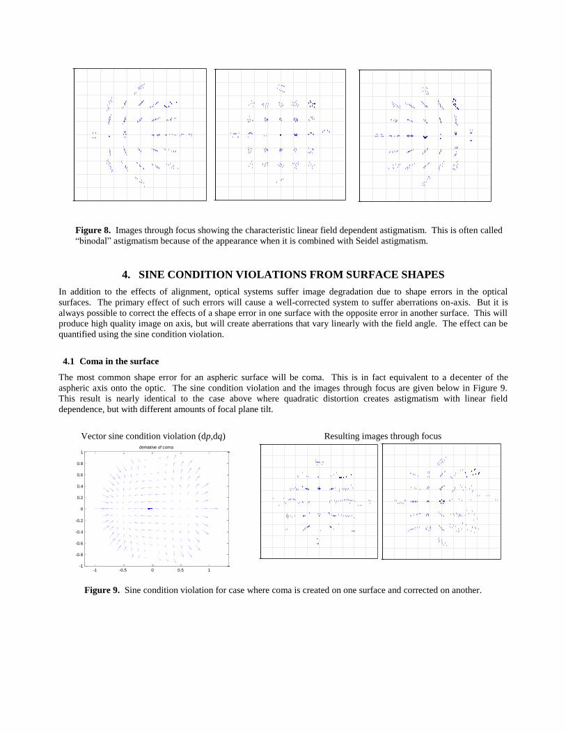
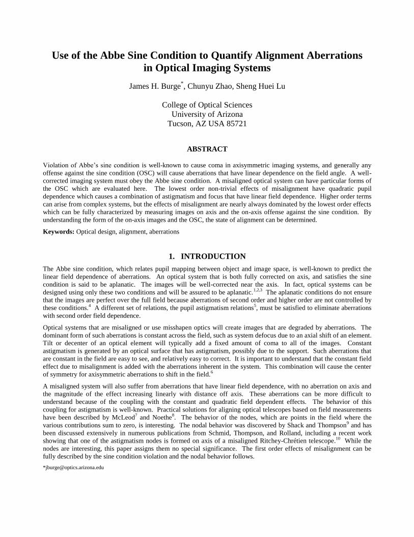
Figure 8. Images through focus showing the characteristic linear field dependent astigmatism. This is often called
“binodal” astigmatism because of the appearance when it is combined with Seidel astigmatism.
4. SINE CONDITION VIOLATIONS FROM SURFACE SHAPES
In addition to the effects of alignment, optical systems suffer image degradation due to shape errors in the optical
surfaces. The primary effect of such errors will cause a well-corrected system to suffer aberrations on-axis. But it is
always possible to correct the effects of a shape error in one surface with the opposite error in another surface. This will
produce high quality image on axis, but will create aberrations that vary linearly with the field angle. The effect can be
quantified using the sine condition violation.
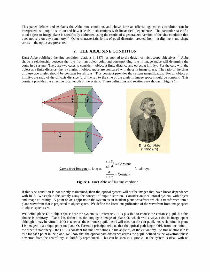
4.1 Coma in the surface
The most common shape error for an aspheric surface will be coma. This is in fact equivalent to a decenter of the
aspheric axis onto the optic. The sine condition violation and the images through focus are given below in Figure 9.
This result is nearly identical to the case above where quadratic distortion creates astigmatism with linear field
dependence, but with different amounts of focal plane tilt.
Vector sine condition violation (dp,dq)
-1 -0.5 0 0.5 1-1
-0.8
-0.6
-0.4
-0.2
0
0.2
0.4
0.6
0.8
1derivative of coma
Resulting images through focus
Figure 9. Sine condition violation for case where coma is created on one surface and corrected on another.
4.2 Trefoil in the surface
A common shape error for mirror is trefoil, a 3-lobed shape error that is one of the lowest bending modes. The sine
condition violation and the images through focus are given below in Figure 10. This results in a second form of linear
field dependent astigmatism. This aberration has been seen other places,15,16
but has not been studied.
Vector sine condition violation (dp,dq)
-1 -0.5 0 0.5 1-1
-0.8
-0.6
-0.4
-0.2
0
0.2
0.4
0.6
0.8
1
derivative of trefoil
Resulting images through focus
Figure 10. Sine condition violation for case where trefoil (r3cos (3)) is created on one surface and corrected
on another. The resulting aberration is a second form of linear field dependent astigmatism.
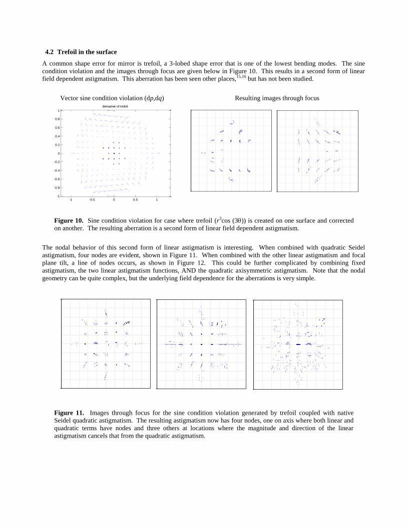
The nodal behavior of this second form of linear astigmatism is interesting. When combined with quadratic Seidel
astigmatism, four nodes are evident, shown in Figure 11. When combined with the other linear astigmatism and focal
plane tilt, a line of nodes occurs, as shown in Figure 12. This could be further complicated by combining fixed
astigmatism, the two linear astigmatism functions, AND the quadratic axisymmetric astigmatism. Note that the nodal
geometry can be quite complex, but the underlying field dependence for the aberrations is very simple.
Figure 11. Images through focus for the sine condition violation generated by trefoil coupled with native
Seidel quadratic astigmatism. The resulting astigmatism now has four nodes, one on axis where both linear and
quadratic terms have nodes and three others at locations where the magnitude and direction of the linear
astigmatism cancels that from the quadratic astigmatism.

Figure 12. Images through focus for the sine condition violation generated by trefoil coupled with linear
astigmatism from alignment and focal plane tilt. The resulting astigmatism now has a nodal line where all
astigmatism terms cancel.
5. DISCUSSION
We present a heuristic development of the relationship between sine condition violations and aberrations that have linear
field dependence. Such aberrations arise in optical design in the form of Seidel coma. Non-symmetric sine condition
violations also come about from alignment or surface figure errors. There exists a one-to-one mapping between the sine
condition violations and the linear field dependent aberrations. Thus it is possible to eliminate such aberrations with
only on-axis measurements if both the on-axis images and the pupil distortions are measured.
REFERENCES
1. G. D. Wasserman and E. Wolf, “On the theory of aplanatic aspheric systems,” Proc. Phys. Soc. B 62, 2-8 (1949).
2. L. Mertz, “Geometrical design for aspheric reflecting systems,” Appl. Opt. 18, 4182-4186 (1979).
3. J. H. Burge and J. R. P Angel, “Wide field telescope using spherical mirrors,” Proc. SPIE 5174, 83-92 (2004).
4. T. Anderson, “Some properties of Mertz-type aspheric surfaces,” Opt Eng, 47(9), 093001 (2008).
5. C. Zhao and J. H. Burge, “Conditions for correction of linear and quadratic field-dependent aberrations in plane-symmetric optical
systems,” JOSA A 19, 2467-2472 (2002).
6. R. A. Buchroeder, Tilted component optical systems, Ph.D. dissertation, Optical Sciences (University of Arizona, Tucson, Arizona, 1976).
7. B. A. McLeod, "Collimation of Fast Wide-Field Telescopes," Publ. Astron. Soc. Pac. 108, 217-219 (1996).
8. L. Noethe and S. Guisard, “Final alignment of the VLT,” Proc. SPIE 4003, 382 (2000).
9. R. V. Shack and K. Thompson, “Influence of alignment errors of a telescope system on its aberration field,” Proc. SPIE 251, 146–153 (1980).
10. T. Schmid, K. P. Thompson, and J. P. Rolland, “A unique astigmatic nodal property in misaligned Ritchey-Chrétien telescopes with misalignment coma removed,” Opt. Express 18, 5282-5288 (2010).
11. C. Zhao, “General sine condition for plane-symmetric imaging systems and some example aplanatic designs,” Proc. SPIE 6342, 634209 (2006).
12. E. Abbe, “Beitrage zur Theorie des Mikroskops und der mikroskopischen Wahrnehmung,” Archiv fuer mikroskopische Anatomie
9, pp. 413-468, (1873). 13. C. Zhao and J. H. Burge, “Criteria for correction of quadratic field dependent aberrations,” JOSA A 19, 2313-2321 (2002).
14. J. H. Burge, C. Zhao, and S. Lu, “Explanation of relationship between the Abbe sine condition and aberrations with linear field
dependence,” to be submitted to Optical Engineering (2010).
15. J. M. Howard and L. D. Feinberg, “Optical modeling activities for NASA's James Webb Space Telescope (JWST): VI. Secondary Mirror Figure Compensation using Primary Mirror Segment Motions”, Proc. SPIE 7436, 74360C, (2009).
16. A. M. Manuel, Field-Dependent Aberrations for Misaligned Reflective Optical Systems, Ph. D. dissertation, Optical Sciences, (University of Arizona, Tucson, Arizona, 2009).