user guide · 2020-03-03 · the system works correctly in a wide operating limits absolute maximum...
TRANSCRIPT
Last update on DECEMBER 22, 2016 www.gatee.eu
USER GUIDE

Notice
Safety Summary
DANGER!
FOR YOUR SAFETY
Information contained in this document is subject to updating without notice.
You should program your MERF 3.2 before the first use.
FOR YOUR OWN SAFETY, PLEASE READ THIS USER MANUAL
CAREFULLY BEFORE INSTALLING THE DEVICE
THE DEVICE COVER MUST NOT BE REMOVED BY THE USER
Caution must be exercised to prevent short circuiting the battery as the
consequences can be very dangerous.
We recommend that this product should be installed by an experienced airsoft
service.
USER GUIDE
02 WWW.GATEE.EU
Please be careful, there are some fake MERF 3.2 being sold on the Internet.
They are manufactured from cheap and low quality components. Using the
fake MERF 3.2 is dangerous and may damage your gun and battery.
HOW TO RECOGNIZE A FAKE MERF 3.2?
- green soldermask
- no original box

CERTIFICATE OF CONFORMITY
The symbol shown here means that the product is classed as Electrical or Electronic Equipment and should not be disposed with other household and commercial waste at the end of its working life. The Waste of Electrical and Electronic Equipment (WEEE Directive 2012/19/UE) has been put in place to recycle products using best available recovery and recycling techniques to minimize the impact on the environment. Purchasers shall take any old electrical equipment to waste recycling public centers or points of sale.
PRODUCT DISPOSAL INSTRUCTIONS
GATE Menet, Wojtak Sp. J. hereby declares under our sole responsibility that the productGATE MERF 3.2 is in conformity with the essential requirements of the following Directives:EC DIRECTIVE 2011/55/EUThis product has been certified as RoHS Compliant.
WARNING:
WARNING:
WARNING:
NOTE:
Before starting installation process, please ensure that your AEG is
empty and there are no BBs inside.
Always use a fuse between the battery and the AEG controller.
Incorrectly connecting positive and negative battery terminals will
cause immediate damage to the unit and it can lead to fire.
Please check if you have downloaded the latest manual from the Technical Support
section of our website: www.gatee.eu. The Product Warranty Form is also
available there.
In case you have any difficulties while installing or using this product, we
recommend to email us at [email protected].
USER GUIDE
03WWW.GATEE.EU
GATE Menet, Wojtak Sp. J. does not take any responsibility for damages, injuries
and accidents resulting in the use of this product or the use of Air Electric Gun
with the product installed.

Table of Contents:
Safety Summary ........................................................................................................2
Table of Contents .......................................................................................................4
01. Overview ..............................................................................................................5
• Key Functions .........................................................................................................6
• Package Contents ...................................................................................................9
02. Installation ..........................................................................................................10
• Simple ...................................................................................................................10
• Enhanced ..............................................................................................................10
03. Set up your MERF 3.2 ....................................................................................12
04. Menus ................................................................................................................14
• Sub-Menus ...........................................................................................................15
• Factory Settings ....................................................................................................17
05. Burst Time setting .............................................................................................17
06. GATE Limited Warranty Policy ..........................................................................20
USER GUIDE
04 WWW.GATEE.EU

01. Overview
Multifunctional programmable 3rd generation MOSFET. The AEG controller has 11
functions. Its latest feature is the 3-rd Burst Mode, which allows for limiting the
number of shots. MERF 3.2 allows for lossless rate of fire adjustment. It protects
Li-Ion batteries: LiPoly and LiFePO4. It has a built-in active brake and it protects
contacts against damage. The Smart Trigger function enables achieving faster
trigger response. Thanks to two operating modes, the system works with both the
original and the modified AEG installation. The system is designed for all replicas
and especially for the upgraded ones. It has been adapted to work even with the
most powerful springs, including M170.
Main Functions Features
• MOSFET
• Active Brake
• Electronic Fuse
• Battery Protection
• Over temperature protection
• Debouncingrd• 3 Gen MOSFET
• ROF Control
• Smart Trigger
• 3-rd Burst
• Plug&Play
•
range of voltages 3.2 - 15V
• Compatibility with the strongest AEG
replicas
• Simple installation
• Protections
• Very low current consumption in
stand-by (0.15mA)
• Very low resistance ~2,4mΩ
• Compatible with all types of GearBox
• 4 LED Display
• DEANS-T Connectors
The system works correctly in a wide
Operating Limits Absolute Maximum Ratings
Battery Voltage
Battery Type
Spring
7.2 - 12.8V
NiCd, NiMH, Li-ion,
Li-Poly, LiFePO4
M170, M210
Supply Voltage
Maximum continuous current
Maximum current (3 min)
Resistance
3.2 - 15V
35A
50A
2.4mΩ
USER GUIDE
05WWW.GATEE.EU

Key Functions
Do you want to achieve higher rate of fire and faster trigger response? Are you planning power upgrade of your rifle? In that case, you needa MOSFET.It targets the energy from the battery directly to the motor, bypassing the mechanical trigger contacts. As a result, you gain a higher rateof fire of the rifle and faster trigger response, and the contactsare protected against burn out.
MOSFET
Do you care about realism? Would you like to increase the life of the gearbox? Does your rifle have such high rate of fire that you are not able to make a single shot? Active brake sorts things out.In SEMI Mode, the brake does not allow for compressing a piston after a shot. The piston will stop in front position which eliminates unnecessary stresses, increasing the service life of gearbox andits parts. It is very important, especially with an AEG power upgrade.After releasing the trigger, the rifle immediately stops firing. Thus, you gain more realism and, additionally, you do not waste your precious ammunition.
Active Brake
We know how important reliability is on the battlefield. That’s why our new MOSFET has thermal protection. In tandem with a time-lag fuse, it fully protects your AEG installation.
Electronic Fuse
Modern LiPoly batteries are very sensitive to over-discharge. If you do not want to damage the battery and you care about its service life, this protection is indispensable. The microprocessor constantly monitors the battery voltage. When it drops down to a critical level, it will not permit firing.
Protection against Over-Discharge of Battery (UVP Protection)
This provides full compatibility with the micro-switches. It is fully resistant to contact bounce. You gain a bigger ROF, a faster trigger response and your MOSFET is less prone to heating.
Debouncing (Digital Interface)
USER GUIDE
06 WWW.GATEE.EU

It enables lossless reduction of rifle’s rate of fire, so you can use stronger LiPo batteries, and still have ROF just like in a real gun.
Rate Of Fire Control
We know how vital the fast trigger response is during combat. Victory is often a matter of fractions of seconds. This is why we have developed the Smart Trigger function. This function enables youto achieve faster trigger response.It works with the ROF Control system. During the first shot, the microprocessor sets ROF Control to 100%. After the first shot, it is switched to the previously programmed value, e.g. 30%. Asa consequence, the first shot is fired with full rate of fire,and subsequent ones with a reduced ROF. The best results can be achieved by using a battery with higher voltage than a standard one. For example, if we use a 7.4V battery, we can change it to 11.1V. In this way, we will achieve faster trigger response with the same rate of fire as with a standard battery.
Smart Trigger
Burst mode enables you to make 3-shot series. In this way you can save ammunition and increase the realism. You can change AUTO mode to BURST mode or SEMI* mode to BURST mode.If in SAFE/SEMI/BURST mode you release the trigger earlier, you can make one or two shots. The burst time is set in the menu with accuracy to 4ms. The processor actively compensates for the change in burst time with a decrease in the rate of fire due to battery discharging.*SEMI to BURST in enhanced mode only
3-rd burst mode
The usage of modern transistors and microcontroller has enabled us to create the smallest and most reliable AEG Controller in the market.
3rd Generation MOSFET
USER GUIDE
07WWW.GATEE.EU

You can connect the system to a rifle in two ways. Depending on the selected method, you should set a proper operating mode: Plug&Play or EnhancedPlug&Play: All you need to do is connect the system betweenthe battery and the rifle.Enhanced Mode: It requires modification of AEG installation.Connect trigger contacts to MERF 3.2. You can do it using the signal wire attached to the kit.
Operating Modes
The function gives you the option to program your fire selector. There are five modes:
- STOCK WIRING SEMI/AUTO- STOCK WIRING SEMI/BURST- MODIFIED WIRING SEMI/AUTO- MODIFIED WIRING SEMI/BURST- MODIFIED WIRING BURST/AUTO
USER GUIDE
08 WWW.GATEE.EU

Included in the kit:
MERF 3.2
Additional kit of Deans-T Connectors
Double signal wire for trigger contacts
Single signal wire for trigger contacts
Programming button
01
02 03
04
05
01
02
03
04
05
USER GUIDE
09WWW.GATEE.EU

02. Installation
Thanks to two operating modes, MERF 3.2 works with both standard and
modified installation.
1. Simple installation (no modification to your AEG is required):
Connect MERF 3.2 between the battery and the AEG. You can make configuration
using programming button from the kit.
2. Enhanced installation:
To adapt the standard AEG installation to work with MERF 3.2 you have to get to
the trigger contacts. In case of GB v2 contacts are located inside a gearbox. With a
version 3 gearbox, installation is easier because the contacts are on the outside of
the gearbox. Please consult a local airsoft technician if you have never
disassembled a gearbox before or if you have any installation concerns.
a) Installation of MERF 3.2 without replacement of wires .
Using this method, the original wiring is kept, and the connections are modified.
Referencing Figure 2, de-solder A wire from the one of the trigger contacts and then
solder it to the B wire. It does not matter which wire you disconnect from the trigger
Fig 1. Standard AEG installation
USER GUIDE
10 WWW.GATEE.EU
BATTERY7.2 - 12.8V
AEG Motor
A B
CONTACTS
FUSE
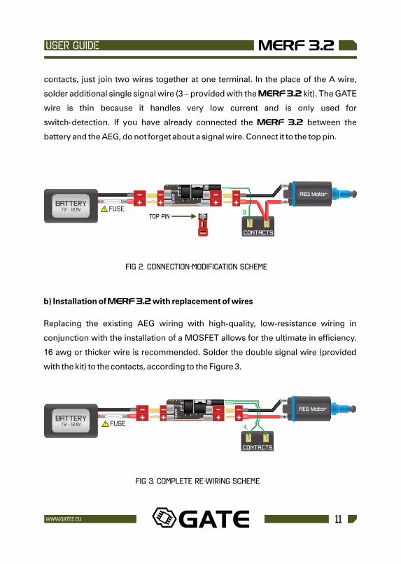
contacts, just join two wires together at one terminal. In the place of the A wire,
solder additional single signal wire (3 – provided with the MERF 3.2 kit). The GATE
wire is thin because it handles very low current and is only used for
switch-detection. If you have already connected the MERF 3.2 between the
battery and the AEG, do not forget about a signal wire. Connect it to the top pin.
Fig 2. Connection-modification scheme
b) Installation of MERF 3.2 with replacement of wires
Replacing the existing AEG wiring with high-quality, low-resistance wiring in
conjunction with the installation of a MOSFET allows for the ultimate in efficiency.
16 awg or thicker wire is recommended. Solder the double signal wire (provided
with the kit) to the contacts, according to the Figure 3.
Fig 3. Complete re-wiring scheme
3.TOP PIN
4.
AEG Motor
CONTACTS
AEG Motor
CONTACTS
BATTERY7.2 - 12.8V
BATTERY7.2 - 12.8V
USER GUIDE
11WWW.GATEE.EU
FUSE
FUSE

03. Set up your MERF 3.2
Step 2. Automatic display test. LEDs light up for a second. 4 LED DISPLAY
ALL ON
Step 3. Automatic software version check. Two LEDs light up for a second. 4 LED DISPLAY
4 LED DISPLAY
Step 1. Connect the battery and the programming button to MERF 3.2
FUSE
4 LED DISPLAY
ALL OFF
BATTERY7.2 - 12.8V
BATTERY7.2 - 12.8V
BATTERY7.2 - 12.8V
USER GUIDE
12 WWW.GATEE.EU
FUSE
FUSE

MERF 3.2 recognizes long and short button presses
Quick Press: NEXT Long Press: ENTER
Step 4A. To activate the Programming Mode in case of simple installation (p.10),press the button quickly.
4 LED DISPLAY
Right Green ON
A B
4 LED DISPLAY
Right Green ON
Step 4B. To activate the Programming Mode in case of enhanced installation (p.10-11) ,disconnect the motor and press the programming button or the trigger quickly.
MERF 3.2 will recognize the absence of the motor and will activate the
Programming Mode.
OR
AEG Motor
CONTACTS
AEG Motor
CONTACTS
BATTERY7.2 - 12.8V
BATTERY7.2 - 12.8V
USER GUIDE
13WWW.GATEE.EU
FUSE
FUSE

04. Menus
4 LEDs Display legend
4 LED DISPLAY 4 LED DISPLAY
LED BLINKING
LEDsOFF
LEDs blinking at the same time
LEDs blinkingalternately
GREEN LEDs show FUNCTION ORANGE LEDs show OPTION
LED ON
4 LED DISPLAY
Right Green ON
Step 4C: while the is
In case of an incorrect configuration, activate the Programming Modeby connecting the battery button pressed.
Press the button quickly to cycle through the main functions of MERF 3.2.
Press and hold the button for about a second if you want to enter a particular
function.
When you enter the function menu, cycle through the function settings by short
presses. Press the button for about a second to enter a chosen setting. Press and
hold the button again and you will be moved back to the Key Functions Menu.
PLEASE NOTE:
Remember to always SAVE your settings after programming
the MERF 3.2, otherwise the session will be lost.
MERF 3.2 remembers the settings after disconnecting the battery.
0102
BATTERY7.2 - 12.8V
USER GUIDE
14 WWW.GATEE.EU
FUSE

Sub-Menus
MAIN MENU
BATTERY
ROF CONTROL
SMART TRIGGER
APPROXIMATE BURST TIME
PRECISE BURST TIME
OPERATING MODES
SAVE & EXIT
LONGPRESS
BATTERY MENU
ROF CONTROLMENU
SMART TRIGGERMENU
APPROXIMATEBURST TIME MENU
PRECISE BURSTTIME MENU
OPERATINGMODES MENU
SAVE & EXIT
QUICKPRESS
NiCd 7.2V
NiCd 8.4V
NiCd 9.6V
NiCd 10.8V
NiCd 12V
LiPoly 7.4V
LiPoly 11.1V
LiFePO 9.6V4
LiFePO 12.8V4
BATTERY MENU
30%
40%
50%
60%
70%
80%
90%
100%
ROF CONTROL MENU
Quick Press: NEXT SETTING
Long Press: SAVE & EXIT TO
MAIN MENU
USER GUIDE
15WWW.GATEE.EU

96ms
128ms
160ms
192ms
224ms
288ms
352ms
416ms
APPROXIMATEBURST TIME MENU
+0ms
+4ms
+8ms
+12ms
+16ms
+20ms
+24ms
+28ms
PRECISEBURST TIME MENU
+0ms
+8ms
+16ms
+24ms
+32ms
+40ms
+48ms
+56ms
OPERATING MODES MENU
ENHANCED MODE SEMI/AUTO
ENHANCED MODE SEMI/BURST
ENHANCED MODE BURST/AUTO
SIMPLE MODE SEMI/AUTO
SIMPLE MODE SEMI/BURST
OFF
ON
SMART TRIGGER MENU
MERF 3.2 offers 64 settings of burst time for your AEG.
Settings up to 192 ms in the Approximate Burst Time Menu let you adjust
by 4 ms increments in the Precise Burst Time Menu.
Settings from 224 - 416 ms in the Approximate Burst Time Menu, can be
adjusted by 8 ms increments in the Precise Burst Time Menu.
USER GUIDE
16 WWW.GATEE.EU

To restore Factory Settings activate the programming mode and input the settings
listed below.
BATTERY
ROF CONTROL
SMART TRIGGER
APPROXIMATE BURST TIME
PRECISE BURST TIME
OPERATING MODES
ORIGINAL SETTINGS
NiCd 7.2V
100%
OFF
288ms
+0ms
ENHANCED MODE SEMI/AUTO
FACTORY SETTINGS
BURST TIME
96ms
128ms
160ms
RATE OF FIRE IN SHOTS PER SECOND
31 rps
23 rps
18 rps
05. Burst Time setting
MERF 3.2 allows you to use 3-rd burst firing mode. It supports replicas which rate
of fire ranges from 7 to 31 shots per second. Set Burst Time in menu to calibrate
burst.
Burst Time is time of three shots expressed in millisecond. One millisecond (1ms) is a
thousandth (0.001) of a second. You can set it up with a resolution 4ms for times 96ms -
220ms, and with a resolution 8ms for times 224ms - 472ms.
Table (approximate):
The theoretical explanation
USER GUIDE
17WWW.GATEE.EU

Precise Burst Time adds to the Burst Time the selected value.
Example 1:Burst Time: 160ms
Precise Burst Time: +8ms / +16ms
Result : 160ms+8ms=168ms
Example 2:Burst Time: 224ms
Precise Burst Time: +8ms / +16ms
Result: 224ms+16ms=240ms
You can set 64 different Burst Times on the display which has only four segments.
192ms
224ms
288ms
352ms
416ms
15
13 rps
10 rps
8 rps
7 rps
rps
The practical explanation
There are two ways for Burst Time setting: setting by hearing or setting by making a
measurement of rate of fire via a microphone or chronometer.
a) Burst Time setting by hearing (if you do not know the ROF):
1. Set approximate Burst Time on three shots
2. Reduce the approximate Burst Time by one level
3. Check if your AEG fires two shots (if not - get back to Step 2)
4. Go to the menu Precise Burst Time and increase it by one level
5. Check if your AEG fires three shots (if not - get back to Step 4)
6. THE END
You have just set the burst on three shots so as the piston stops in the front position
without causing stress in the gearbox.
USER GUIDE
18 WWW.GATEE.EU
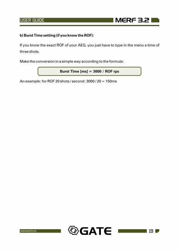
b) Burst Time setting (if you know the ROF):
If you know the exact ROF of your AEG, you just have to type in the menu a time of
three shots.
Make the conversion in a simple way according to the formula:
Burst Time [ms] = 3000 / ROF rps
An example: for ROF 20 shots / second: 3000 / 20 = 150ms
USER GUIDE
19WWW.GATEE.EU

06. GATE Limited Warranty Policy
GATE Menet, Wojtak Sp. J. warrants that its Product is free from manufacturing and
material defects at the date of purchase and for a period of one (1) year from the date
of purchase and it is not-extendable. This Limited Warranty is conditioned upon
proper use of Product by Purchaser.
1. This Limited Warranty is valid provided that the owner provides a proof of
purchase and properly completed warranty form. The warranty form is available on
our website: http://www.gatee.eu/ .
2. This Limited Warranty does not cover: (a) defects or damage (eg. mechanical,
thermal or chemical) resulting from accident, misuse (misinterpretation of the
instructions), abuse, neglect, unusual physical, electrical or electromechanical
stress, water immersion, repairs or structural modification of any part of Product
(eg. heat-shrink tube removal), or (b) the Product that has the serial number
removed or made illegible; (c) defects or damage from improper operation,
maintenance or installation, (d) installation of the products.
3. Requests for warranty are processed as soon as possible, not exceeding seven
(7) working days. The company's obligation under this Limited Warranty shall be
limited to providing replacement of part/s only.
Contact: [email protected]
USER GUIDE
20 WWW.GATEE.EU