user and maintenance manual - atlantic boilers m series m116/m450 user and maintenance manual page...
TRANSCRIPT

0MEM0227-E_GB M Series M116/M450 User and Maintenance Manual Page 1/20
M SERIES
M116 / M450
USER AND MAINTENANCE MANUAL
FOR MODULATING-CONTROL BOILER
WITH GAS BURNER EQUIPPED FOR NATURAL GAS
Type : B23
Country BE CH ES FR GB IE IT LU NL PT
Category I2E(R)B I2H I2H I2Esi I2H I2H I2H I2E (G20) I2L I2H
This device complies with the following European Community Directives:
- Low voltage (73/23/CEE) - Electromagnetic compatibility (89/336/CEE) - Efficiency (92/42/CEE) - Gas device (90/396/CEE) - BS 5978 parts 1 & 3
Customer service for your boiler is ensured by:
ATLANTIC 2000�PO Box 11 Ashton Under Lyne OL6 7TR +44. (0) 161 621 5960 Fax +44. (0) 161 621 5966 [email protected] www.atlanticboilers.com

0MEM0227-E_GB M Series M116/M450 User and Maintenance Manual Page 2/20

0MEM0227-E_GB M Series M116/M450 User and Maintenance Manual Page 3/20
TABLE OF CONTENTS
TABLE OF CONTENTS _________________________________________________________ 3
1. Technical characteristics M220-M270. ____________________________________________ 4
2. Technical characteristics M116-M145-M180/M330-M390-M450. ______________________ 5
3. Installing the boiler. ___________________________________________________________ 6
4. Commissioning._______________________________________________________________ 6
5. Shutdown. ___________________________________________________________________ 6
6. Servicing. ____________________________________________________________________ 6
7. No-frost._____________________________________________________________________ 7
7.1. No-frost M220-M270 ______________________________________________________________ 7
7.2. No-frost M116-M145-M180 / M330-M390-M450 _______________________________________ 7
8. User interface and boiler regulation. ______________________________________________ 8
8.1. Description of interface ____________________________________________________________ 8
8.2. LCD display _____________________________________________________________________ 8
8.3. Operating modes _________________________________________________________________ 9
8.4. Setting the setpoints ______________________________________________________________ 10
8.5. Boiler status information__________________________________________________________ 11
8.6. Parameter definitions ____________________________________________________________ 13
9. Control unit operation. ________________________________________________________ 14
10. Summary table of client parameters_____________________________________________ 16

0MEM0227-E_GB M Series M116/M450 User and Maintenance Manual Page 4/20
1. Technical characteristics M220-M270. Each M Series boiler is factory adjusted for group H natural gas (type G20) with supply pressure of 20 mbar.
Any intervention on a sealed component will result in loss of warranty. Nominal, maximum and minimum gas supply pressures
Natural gas G20 Nominal pressure (mbar) 20 Minimum pressure (mbar) 17 Maximum pressure (mbar) 25 Combustion characteristics at 15°C and 1013 mbar. Model M220 M270 Nominal power P (kW) 220.0 270.0 Heat release Q (kW) 240 294 Gas flowrate : G20 (m3/h) G25 (m3/h)
25.4 29.5
31.1 36.1
Smoke flowrate (g/s) 103.9 126.8 Smoke temperature (°C) 160 160 Fresh air flowrate (m3/h) 291 355 Hydraulic loss (daPa) 970 at 9.5 m3/h 1400 at 11.6 m3/h 100 daPa = 0.102 mCE Characteristics for electrical connection. Model M220 M270 Electrical power absorbed (boiler without accessories) (W) 580 635
Electrical power supply (V) 230V AC +10% -15% Full load amperes (A) 10 10
Max. length of sensor cables HWS sensor= 10m External sensor 40m
Comfort thermostat 40m Ambient temp. sensor 50m
Power terminal strip outputs (V) 230V AC +10% -15% 5 mA to 2A
Other characteristics: Maximum working pressure : ...................... PMS = 6 bar . Maximum operating temperature :............... 85 °C ,(factory adjusted for 80°C).

0MEM0227-E_GB M Series M116/M450 User and Maintenance Manual Page 5/20
2. Technical characteristics M116-M145-M180/M330-M390-M450. Each M Series boiler is factory adjusted for group H natural gas (type G20) with supply pressure of 20 mbar. If the gas network used is a 300 mbar system, mount the Gas pressure regulator kit.
Any intervention on a sealed component will result in loss of warranty. Nominal, maximum and minimum gas supply pressures.
Natural gas G20 Nominal pressure (mbar) 20 Minimum pressure (mbar) 17 Maximum pressure (mbar) 25 Combustion characteristics at 15°C and 1013 mbar. Model M116 M145 M180 M330 M390 M450 Nominal power P (kW) 116 145 180 330 390 450 Maximum Heat release Q (kW) 122 155 192 349 415 472 Minimum Heat release Q (kW) 31.5 39 48 88 105 118 Gas flowrate : G20 (m3/h) 12.9 16.4 20.3 36.9 43.9 50.0 Diameter diaphragm G20 (mm) - - - - 17,3 17,7 Smoke flowrate (g/s) 52.1 66.3 81.4 150.6 179 203.6 Smoke temperature (°C) 110 115 120 130 130 130 Fresh air flowrate (m3/h) 146.0 185.5 227.7 421.7 501.4 570.4
Hydraulic loss (daPa) 850 à 5m3/h
1050 à 6.25m3/h
1350 à 7.75m3/h
920 à 14.3m3/h
1150 à 16.3 m3/h
1480 à 19.4 m3/h
100 daPa = 0.102 mCE Characteristics for electrical connection. Model M116 M145 M180 M330 M390 M450 Electrical power absorbed (boiler without accessories) (W) 420 440 460 620 640 820
Electrical power supply (V) 230 V AC +10 % -15 % 50 Hz Full load amperes (A) 8 8 8 10 10 12
DHW sensor : 10 m Comfort thermostat : 40 m Max. length of sensor cables External sensor : 40 m Ambient temp. sensor : 50 m
230 V AC +10 % -15 % Power terminal strips Outlet 5 mA à 2 A
Other characteristics : Maximum working pressure PMS (see nameplate):
4 bar for M116-M145-M180 6 bar for M330-M390-M450
Maximum operating temperature: 85 °C, (factory adjusted for 80°C).

0MEM0227-E_GB M Series M116/M450 User and Maintenance Manual Page 6/20
3. Installing the boiler. The boiler must be installed by a qualified professional in compliance with trade practices and the requirements specified in the installation manual. The boiler must be installed in a room having appropriate air inlets complying with applicable rules and regulations (see installation and maintenance manual).
4. Commissioning. Before packaging, all boilers are tested in factory with group H natural gas (type G20) during which all the adjustments are performed. For this reason, startup is limited to the following points: The power is limited to 65% of its rated value and the maximum temperature is also limited to 70°C up to commissioning. It is highly recommended the commissioning procedure be performed by our Customer Technical Assistance Department. Provisional commissioning can be performed as follows: 1. Switch on the main power switch. 2. Initiate a heat request in comfort mode using the customer interface (see “Interface presentation”
paragraph). 3. Once the burner is operating, check the tightness of the gas line couplings using a non
combustible product. Check the performance of the combustion (via a calibrated combustion analyzer).
4. Set the clock to the correct time (Refer to the client parameter summary table at the end of this manual).
Any interventions on a sealed component will result in loss of warranty.
5. Shutdown. Proceed as follows to shut down the boiler : 1. Switch off the main switch. 2. Close the gas supply isolating valve.
6. Servicing. The boiler must be serviced on an annual basis. A qualified professional must be called in for all servicing operations (see installation manual).

0MEM0227-E_GB M Series M116/M450 User and Maintenance Manual Page 7/20
7. No-frost. The warranty is only effective provided the heating network contains an antifreeze should there be any risk of freezing in the installation. If the user nonetheless decides to drain the boiler, it is the user’s responsibility to ensure that no water remains in the boiler.
7.1. No-frost M220-M270
Instructions for draining boiler and burner : Drainage should be carried out in two stages: I. Draining the heat exchanger: • close the stop valves of the outlet and return
connections • create an air inlet at the tope of the boiler pipe
assembly (by opening the safety valve); • open the boiler drain cock (refer to chapter 1).
II. When no more water runs out, drain the burner: • Disconnect and remove the ignition electrode
unit (item 3) to protect it against water damage.
• disassemble connection of hose (item �) where it joins the “Boiler return” connection, taking care to ensure that no water falls onto the boiler.
• unscrew the brass cover of the burner drain connection (item �), again taking care to ensure that no water falls onto the boiler.
• insert a flexible tube into this connection and push it right down to the bottom of the burner;
• remove the water remaining in the burner by suction or siphoning;
• remove the tube, replace the connection cover, re-connect the hose (check the seal).
• Re-install and connect the ignition electrode unit (item 3) after checking the condition of its o-ring (replace it if necessary).
7.2. No-frost M116-M145-M180 / M330-M390-M450
• Switch off the main switch. • Close the gas supply shutoff valve. • Hydraulically isolate the boiler ; • Create an air intake at the top of the return and outlet pipes of the boiler (safety valve open) and
open the boiler drain tube valve.
1
2
3

0MEM0227-E_GB M Series M116/M450 User and Maintenance Manual Page 8/20
8. User interface and boiler regulation.
8.1. Description of interface The boiler customer interface comprises a main switch, a drawer-type fuse-holder, an electronic board with a backlighted LCD screen (two 4-digit lines + pictograms) and 10 buttons. A pre-cut mounting position for 2 regulators (96x96) or 1 regulator (144x96) is also provided. All the customer settings and possible parameter definitions are performed using this interface. The interface also enables the user to read information concerning operation of the boiler.
8.2. LCD display In its standard version, the screen displays the boiler status (operating mode, time, heating time program, boiler temperature, presence of flame, possible fault).
Mode selection buttons Programming buttons Information button Boiler main on/off switch
Setpoint adjustment buttons
Reset button
Pre-cut position for regulators
Boiler fuse-holder
Summary of heating time clock : Each small square represents a heating period in comfort mode (in slots of 1 hour). The flashing square indicates the current hour.
Heating mode Time Boiler temperature
DHW mode Symbols :
DHW preparation in progress or display of DHW temp.
Heating active, or boiler setpoint temp. or ambient temp.
Comfort mode
Economy heating mode External temp. display
Flame present Alarm

0MEM0227-E_GB M Series M116/M450 User and Maintenance Manual Page 9/20
When a non-blocking fault appears, the time display alternates with the fault code display. This does not result in a lockout condition. When a fault places the boiler in a lockout condition, the fault code is displayed flashing in place of the boiler temperature. A small bell appears at the lower left of the display. Refer to the paragraph on “Error messages” to interpret the fault codes. In the last two cases, briefly press the information button to display the fault code alone. Simultaneously press the and buttons to display the extended fault code (Press then or
to return to the standard display).
8.3. Operating modes Heating mode button This button selects the heating mode among the Stop, Auto, Comfort and Eco modes
Standby 1. No request for internal heat is taken into account. The frost protection remains active.
2. The requests for external heat (0-10v or bus LPB)
remain active, except cascade application.
Comfort Permanent “comfort” mode. The boiler power is
adapted to satisfy the heating setpoint (heating setpoint button).
Eco Permanent reduced heating mode. The boiler power
is adapted to satisfy the ECO setpoint (parameter no. 5) (see paragraph 4.6, parameter definitions).

0MEM0227-E_GB M Series M116/M450 User and Maintenance Manual Page 10/20
Auto Depending on the heating time program, the
regulator alternates between the Comfort and Eco modes.
DHW mode button Active / in-active Domestic Hot Water
active DHW production in-active DHW production
8.4. Setting the setpoints Setting the heating setpoint Depending on the regulation mode selected, the setpoint temperature takes a different meaning: • In constant temperature mode, the setpoint is a water temperature at the heater outlet. • In regulation mode, depending of the outside temperature, or the ambient temperature, or both,
the setpoint is an ambient temperature. Press the heating setpoint button . The current setpoint value is displayed. Press the or buttons to adjust the heating temperature setpoint. Press the heating mode button , the DHW mode button , or the heating setpoint button to exit the setpoint adjustment screen. If no button is pressed for around 8 minutes, the interface returns to the standard display. Setting the DHW setpoint This function can only be accessed provided an DHW production is connected to the boiler. Press on the domestic hot water setpoint button . The current setpoint value is displayed. Press the or buttons to adjust the domestic hot water temperature setpoint. Press the heating mode button , the DHW mode button , or the DHW setpoint button to exit the setpoint adjustment screen. If no button is pressed for around 8 minutes, the interface returns to the standard display.
The DHW setting must be defined according to the regulation required in the country to avoid all risks with respect to the legionnella.
1

0MEM0227-E_GB M Series M116/M450 User and Maintenance Manual Page 11/20
8.5. Boiler status information Info button At any time, you can scroll the basic boiler information by pressing the Info button . Each time the Info button is pressed, the next variable is displayed.
1 DHW temperature
2 Not used
3 Burner operating phase code (refer to “Burner phase codes” sub-paragraph)
4 Outdoor temperature
5 Albatros3 error code (refer to “Error messages” sub-paragraph)
6 Boiler temperature
To return to the standard display, press on either of the or buttons 3 Albatros : name given by SIEMENS for fault codes.

0MEM0227-E_GB M Series M116/M450 User and Maintenance Manual Page 12/20
Error code display In the event of a fault resulting in lockout of the LMU, the alarm signal is displayed continuously and the fault code flashes. To reset the LMU, eliminate the source of the fault, then press the reset
button for at least 2 seconds.
Fault code Potential cause
0 No entry in Albatros code made 10 Fault outside sensor 20 Fault boiler temperature sensor 1 40 Fault return temperature sensor 1 50 Fault domestic hot water temperature sensor 1 52 Fault domestic hot water temperature sensor 2 61 Fault room unit 1 62 Wrong room unit 1 or wrong radio clock connected 81 Short-circuit on LPB bus, or no bus power supply 82 Address collision on LPB bus (several identical addresses) 91 Data overflow in EEPROM 92 Hardware fault in electronics
100 Two clock time masters in system 105 Preventive maintenance 110 Safety thermostat tripped 111 Limit thermostat has tripped 119 Water pressure switch has tripped 132 Safety shutdown (e.g. by gas pressure switch) 133 No establishment of flame on completion of safety time
128/134 Loss of flame during operation 129/135 Wrong supply of air*
140 inadmissible LPB… segment number or device number 148 Incompatibility LPB… interface/basic unit 151 Internal fault LMU 152 Fault in connection with LMU… parameter settings 153 LMU… has locked out 154 Plausibility criteria violated 160 Fan speed threshold not reached 161 Maximum fan speed exceeded 164 Fault heating circuit flow switch / pressure switch 180 Chimney sweep function active 181 Controller stop function active 183 LMU… in parameter setting mode
* For the M450 model, the appearance of this error code can be related to the detection of a variation of speed between the 2 fans, via the electronic chart Twin Fan located in the control panel (See chapter Exploded view of control panel). Under normal operation, the red indicator of this chart flickers. At the time of a setting in safety for the code defect described above, this indicator remains lit permanently.

0MEM0227-E_GB M Series M116/M450 User and Maintenance Manual Page 13/20
Burner phase codes To consult the burner phase codes, press the Info button three times. (As indicated on page 17)
Display code Meaning
0 Standby (no demand for heat) 1 Startup blocked 2 Fan start 3 Pre-purging 4 Waiting time 5 Pre-ignition time 6 Safety time
10 Heating operation 11 DHW operation 12 Parallel operation of space heating and DHW heating 20 Post purging 22 Home running 99 Lockout position (display of the current error code)
8.6. Parameter definitions To best define the boiler configuration, a certain number of parameters can be modified by the end-user or installer. To secure the boiler configuration, all the parameters are not accessible to the end user. These are therefore grouped by access levels. Starting from the standard display, the end-user parameter definition mode is accessed by pressing either of the or buttons. The display indicates a P followed by a parameter number with 3 digits. The and buttons enable you to scroll the list of parameter numbers. Once you have reached the parameter you wish to modify, adjust its value using the and buttons. The new value is validated as soon as you go to the next or previous parameter or if you exit the mode by pressing the buttons. Caution, if you exit the programming mode using the or buttons, the current parameter change will not be validated. Refer to the client parameter summary table at the end of this manual.

0MEM0227-E_GB M Series M116/M450 User and Maintenance Manual Page 14/20
9. Control unit operation.
Button : PG = Gas pressure switch. CD = Flow controller. TL = Limiter thermostat. = Alarm = Flame detection. = Ignitor electrode = Gas valve = Fan Nmax = Max. speed authorized. N_VL = Max. speed authorized with modulation. N_ZL = Speed on ignition. N_TL = Min. speed authorized with modulation Nzero = Speed less than 200 rpm, therefore considered as null
NOTA : The control unit automatically starts again a new start-up of the burner in the event of failure of the first start-up. For model M116, there is no pre-heating phase No.5 since this model utilizes arc ignition.
Fan speed
0 2 3 4 5 6 10, 11, 12 20 22 1 99 Standby Run up Pre- Wait Pre- Safety Operation Post- Return to Startup Safed
ventilation Heating for hot surface ignition
time ventilation zero blocked
Nmax N_VL N_ZL N_TL Nzero
0
11 s. 3 s. 1,8 s. t
Phase code
PG, CD, TL

0MEM0227-E_GB M Series M116/M450 User and Maintenance Manual Page 15/20

0MEM0227-E_GB M Series M116/M450 User and Maintenance Manual Page 16/20
10. Summary table of client parameters Boiler model: series: site : Please note all modifications to parameters in this document!
Adjustm. line Function Unit Adjustment range Résolution
Default value
Client setting
Time setting P 1 Current hour hh :mm 00 :00 … 23 :59 0 :01 00 :00 P 2 Current day day 1:monday 7:sunday 1 ---
P 5 Reduced room temperature setpoint or reduced boiler temperature setpoint (depending of the regulation mode) °C Tdépartmin…Tdépartmax /
Tambmin…Tambmax 0,5 40 / 15
Time programer heating circuit N°1
P 10
Pre-selection of the day(s) to be programmed: 1-7 => Block complete week 1…7 => Day of the week 1-5 => Block of Monday to Friday 6-7 => Block of Saturday and Sunday
P 11 Time switch switch-on time 1st period hh :mm 00 :00 … 24 :00 0 :10 06 :00 P 12 Time switch switch-off time 1st period hh :mm 00 :00 … 24 :00 0 :10 22 :00 P 13 Time switch switch-on time 2nd period hh :mm 00 :00 … 24 :00 0 :10 24 :00 P 14 Time switch switch-off time 2nd period hh :mm 00 :00 … 24 :00 0 :10 24 :00 P 15 Time switch switch-on time 3rd period hh :mm 00 :00 … 24 :00 0 :10 24 :00 P 16 Time switch switch-off time 3rd period hh :mm 00 :00 … 24 :00 0 :10 24 :00
Time programer heating circuit N°2
P 20
Pre-selection of the day(s) to be programmed: 1-7 => Block complete week 1…7 => Day of the week 1-5 => Block of Monday to Friday 6-7 => Block of Saturday and Sunday
P 21 Time switch switch-on time 1st period hh :mm 00 :00 … 24 :00 0 :10 06 :00 P 22 Time switch switch-off time 1st period hh :mm 00 :00 … 24 :00 0 :10 22 :00 P 23 Time switch switch-on time 2nd period hh :mm 00 :00 … 24 :00 0 :10 24 :00 P 24 Time switch switch-off time 2nd period hh :mm 00 :00 … 24 :00 0 :10 24 :00 P 25 Time switch switch-on time 3rd period hh :mm 00 :00 … 24 :00 0 :10 24 :00 P 26 Time switch switch-off time 3rd period hh :mm 00 :00 … 24 :00 0 :10 24 :00
Time programer DHW
P 30
Pre-selection of the day(s) to be programmed: 1-7 => Block complete week 1…7 => Day of the week 1-5 => Block of Monday to Friday 6-7 => Block of Saturday and Sunday
P 31 Time switch program DHW 1st period on hh :mm 00 :00 … 24 :00 0 :10 06 :00 P 32 Time switch program DHW 1st period off hh :mm 00 :00 … 24 :00 0 :10 22 :00 P 33 Time switch program DHW 2nd period on hh :mm 00 :00 … 24 :00 0 :10 24 :00 P 34 Time switch program DHW 2nd period off hh :mm 00 :00 … 24 :00 0 :10 24 :00 P 35 Time switch program DHW 3rd period on hh :mm 00 :00 … 24 :00 0 :10 24 :00 P 36 Time switch program DHW 3rd period off hh :mm 00 :00 … 24 :00 0 :10 24 :00
P 45 Return to the standard time programming for the heating and the DHW (press both buttons – and + for 3 seconds.) 0
H 90 Reduced DHW temperature setpoint °C 50…65 0,5 60
H 91 Release of DHW :
0 Timed DHW program 1 24h/24
0
H 93 Not used 0 H 94 Not used
H 501 Minimum room setpoint temperature (10°C<=TrSmin<=TrSmax) °C 10…30 0,5 10
H 502 Maximum room setpoint temperature (TrSmin<=TrSmax<=30°C) °C 10…30 0,5 26
H 503 Minimum boiler setpoint temperature (20°C � n°503 � n°504) °C 20…85 0,5 20
H 504 Maximum boiler setpoint temperature (n°503 � n°504 � 85°C) °C 20…85 0,5 85
H 505 Maximum heating setpoint temperature °C 20…85 0,5 80
H 506 Minimum flow setpoint temperature heating circuit n° 2 (20°C � H506 � H507) °C 20…85 0,5 20
H 507 Maximum flow setpoint temperature heating circuit n° 2 (H506 � H507 � 85°C) °C 20…85 0,5 80
H 510 Flow temperature setpoint boost with DHW heating K 0 ... 30 0,5 15
H 511 Boiler frost protection switch-on temperature (5°C�TkSfrostEin<TkSfrostAus) °C 5 … 50 7

0MEM0227-E_GB M Series M116/M450 User and Maintenance Manual Page 17/20
Adjustm. line Function Unit Adjustment range Résolution
Default value
Client setting
H 512 Boiler frost protection switch-off temperature (TkSfrostEin<TkSfrostAus�50°C) °C 5 … 50 15
H 514 Boiler temperature setpoint boost with mixing circuit n°2 K 0 … 30 0,5 2
P 516 Summer/winter changeover temperature (30°C = S/W changeover deactivated) °C 8 … 30 0,5 19
H 517 Maximum control differential; when exceeded, minimum pause time will be aborted K 0 … 90 10
H 523 Switch-on differential of burner in heating mode K 0,5 … 32 0,5 3 H 524 Minimum switch-off differential of burner in heating mode K 0,5 … 32 0,5 3 H 525 Maximum switch-off differential of burner in heating mode K 0,5 … 32 0,5 6
H 526 Switch-on differential of burner in DHW heating mode (sensor 1) K 0,5 … 32 0,5 3
H 527 Minimum switch-off differential of burner in DHW heating mode (sensor 1) K -32 … 32 0,5 3
H 528 Maximum switch-off differential of burner in DHW heating mode (sensor 1) K -32 … 32 0,5 6
H 529 Switch-on differential of burner in DHW heating mode (sensor 2) K 0,5 … 32 0,5 3
H 530 Minimum switch-off differential of burner in DHW heating mode (sensor 2) K -32 … 32 0,5 3
H 531 Maximum switch-off differential of burner in DHW heating mode (sensor 2) K -32 … 32 0,5 6
P 532 Heating curve slope heating circuit 1 1 … 40 1 15
P 533 Heating curve slope heating circuit 2 (Active depending on hydraulic configuration) 1 … 40 1 15
P 534 Room setpoint temperature readjustment heating circuit 1 K -31 … 31 0,5 0
P 535 Room setpoint temperature readjustment heating circuit 2 (Active depending on hydraulic configuration) K -31 … 31 0,5 0
H 536 Maximum speed at maximum output in heating mode (maximum speed limitation) tr/min 0 … 9950 50
MC 116 = 6200 MC 145 = 6000 MC 180 = 6000 MC 220 = 5750 MC 270 = 5550 MC330= 5750 MC390= 6100 MC450= 5950
H 542
Minimum boiler output (lower calorific value)
kW 0 … 9999 1
MC 116 = 30 MC 145 = 36 MC 180 = 45 MC 220 = 85
MC 270 = 105 MC330= 83 MC390= 98
MC450= 112
H 543
Maximum boiler output (lower calorific value)
kW 0 … 9999 1
MC 116 = 116 MC 145 = 145 MC 180 = 180 MC 220 = 220 MC 270 = 270 MC330= 330 MC390= 390 MC450= 450
H 544 Overrun time of pumps, max. 210 min (setting 255: continuous operation of Q1) min 0 … 255 1 5
H 545 Minimum burner pause time (heat demand-dependent switching hysteresis) sec 0 … 3600 1 300
H 546 Minimum burner running time (heat demand-dependent switching hysteresis) sec 0 … 255 1 120
H 551 Constant for quick setback without room temperature influence 0 … 20 1 0
H 552
Hydraulic system adjusment 2 1 Boiler, 1 heating circuit (with pump) with or without DHW 34 1 Boiler, 2 heating circuits (with pumps) with or without DHW 48 1 Boiler, 1 heating circuit (with mixing valve) with or without DHW 50 1 Boiler, 2 heating circuit (1 pump, 1 mixing valve) with or without DHW 64 1 Boiler, x heating circuits (with mixing valves) without DHW 66 1 Boiler, x heating circuits (1 pump, x mixing valves) with or without DHW 80 Boiler cascade-controlled 85 DHW dedicated boiler cascade-controlled
66
H 553
Configuration of heating circuit (with room temperature sensor only) : Tens : influence on CC2, Units : influence on CC1 0 CC2 not influenced by QAA 73 0 CC1 not influenced by QAA 73 1 CC2 controlled by main channel of QAA 73 1 CC1 controlled by main channel of QAA 73 2 CC2 controlled by secondary channel of QAA 73 2 CC1 controlled by secondary channel of QAA 73 e.g.: 12 corresponds to CC1 controlled by sec. channel of QAA 73 and CC2 controlled by main channel of QAA 73
0
H 555.b0 Not used 0
0MEM0227-E_GB M Series M116/M450 User and Maintenance Manual Page 18/20
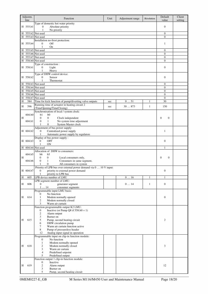
Adjustm. line Function Unit Adjustment range Résolution
Default value
Client setting
H 555.b1 Type of domestic hot water priority 0 Absolute priority
1 No priority 0
H 555.b2 Not used 0 H 555.b3 Not used 0
H 555.b4 Installation no-frost protection:
0 Off 1 On
1
H 555.b5 Not used 0 H 555.b6 Not used 0 H 555.b7 Not used 0 H 558.b0 Not used 0
H 558.b1 Type of construction :
0 Light 1 Heavy
0
H 558.b2 Type of DHW control device:
0 Sensor 1 Thermostat
0
H 558.b3 Not used 0 H 558.b4 Not used 0 H 558.b5 Not used 0 H 558.b6 Not used 0 H 558.b7 Not used 0 H 584 Time for kick function of pump/diverting valve outputs sec 0 … 51 1 30
H 596 Running time of actuator in heating circuit 2 (TimeOpening/TimeClosing) sec 30 … 873 1 150
H 604.b0
604.b1
Synchronisation of local / system clock: b1 b0 0 0 Clock independent 0 1 No system time adjustment 1 0 System Master clock
0 0
H 604.b2 Adjustment of bus power supply:
0 Centralized power supply 1 Automatic power supply by regulators
1
H 604.b3 Display of bus power supply :
0 OFF 1 ON
0
H 604.b4 Not used 1
H 604.b5
604.b6
Allocation of DHW to consumers: b6 b5 0 0 Local consumers only, 0 1 Consumers in same segment, 1 0 All consumers in system
0 0
H 604.b7 Priority of LPB bus over external power demand via 0 … 10 V input:
0 priority to external power demand 1 priority to LPB bus
0
H 605 LPB device number of LMU 0 … 16 1 1
H 606 LPB segment number of LMU:
0 generator segment 1 … 14 consumer segments
0 … 14 1 0
H 614
Programmable input LMU basis: 0 No function 1 Modem normally opened 2 Modem normally closed 3 Warm air curtain
0
H 615
Function programmable output K2 LMU: 0 Inactive (or Pump Q8 if 558.b0 = 1) 2 Alarm output 3 Burner on 5 Pump, second heating circuit 6 DHW circulation pump 7 Warm air curtain function active 8 Pump of pressureless header 12 Analog input signal in operation
2
H 618
Programmable input on clip-in function module: 0 No function 1 Modem normally opened 2 Modem normally closed 3 Warm air curtain
4 Predefined setpoint 5 Predefined output
3
H 619
Function output 1 clip-in function module: 0 Inactive 2 Alarm output 3 Burner on 5 Pump, second heating circuit
12

0MEM0227-E_GB M Series M116/M450 User and Maintenance Manual Page 19/20
Adjustm. line Function Unit Adjustment range Résolution
Default value
Client setting
6 DHW circulation pump 7 Warm air curtain function active 8 Pump of pressureless header 12 Analog input signal in operation
H 620
Function output 2 clip-in function module: 0 Inactive 2 Alarm output 3 Burner on 5 Pump, second heating circuit 6 DHW circulation pump 7 Warm air curtain function active 8 Pump of pressureless header 12 Analog input signal in operation
3
H 622 Maximum temperature of heat demand with external predefined temperature setpoint °C 5 … 130 1 100
H 623 Threshold of analog signal from witch the external demand for output will be accepted (percentage of maximum value of analog signal)
% 5 … 95 1
M116= 25 M145= 25 M180= 25 M220= 37 M270= 37 M330= 25 M390= 25 M450= 25
H 630.b0 Setting flags of maintenance alarms:
0 Alarm desacitvated 1 Alarm activated
0
H 630.b6 Maintenance alarm main clearance 1 Clears the maintenance alarm 0
H 630.b7 Not used 0
H 632.b0 Pump Q8 active for heat demand in LPB zone:
0 No 1 Yes
0
H 632.b1 Pump Q8 active for heat demand in heating circuit n° 2:
0 No 1 Yes
0
H 632.b2 Pump Q8 active for heat demand in heating circuit n° 1:
0 No 1 Yes
0
H 632.b3 Pump Q8 active for DHW heat demand:
0 No 1 Yes
0
H 700 1st past value of lockout code counter
H 701
1st past value of lockout phase Correspondence of the phase codes : 3 Standby 4 Startup blocked 5, 6 Fan run up 7 Prepurging 8, 9, 10 Waiting time 11 Pre-ignition time (only with hot surface igniter) 12, 13, 14, 15 Safety time 16 Stabilisation of the flame 17 Heating mode with modulation 18, 19, 20, 21 Post-purging 0, 1, 2 Home run 22 Lockout
H 702 1st past value of internal diagnostic code H 703 2nd past value of lockout code counter H 704 2nd past value of lockout phase (see H701) H 705 2nd past value of internal diagnostic code H 706 3rd past value of lockout code counter H 707 3rd past value of lockout phase (see H701) H 708 3rd past value of internal diagnostic code H 709 4th past value of lockout code counter H 710 4th past value of lockout phase (see H701) H 711 4th past value of internal diagnostic code H 712 4th past value of lockout code counter H 713 5th past value of lockout phase (see H701) H 714 5th past value of internal diagnostic code H 715 Current value of lockout code counter H 716 Current value of lockout phase (see H701) H 717 Current value internal diagnostic code H 718 Hours run burner H 0 … 131070 1 H 719 Hours run heating mode H 0 … 131070 1 H 720 Hours run DHW heating H 0 … 131070 1 H 721 Hours run zone H 0 … 131070 1

0MEM0227-E_GB M Series M116/M450 User and Maintenance Manual Page 20/20
Adjustm. line Function Unit Adjustment range Résolution
Default value
Client setting
H 722 Start counter 0 … 327675 1
H 724.b0 Selection of summer / Winter operating modes:
0 Summer (no heating) 1 Winter (heating activated)
1
H 725 SW version of LMU for presentation on the OT parameter setting level
H 728 1st past value of ALBATROS error code H 729 2nd past value of ALBATROS error code H 730 3rd past value of ALBATROS error code H 731 4th past value of ALBATROS error code H 732 5th past value of ALBATROS error code H 733 Current value of ALBATROS error code
In italics: read only parameters