user & engineer instruction manual - ambirad ltdsupport.bensonheating.co.uk/manuals/benson iq+...
TRANSCRIPT

USER & ENGINEERINSTRUCTION
MANUAL
HEATMISERIQ+
Revision 1 - 06/09Ref: IQ2
EN IT FR DE NL
USER INSTRUCTIONSCONTENTS PAGE
1
SUBJECT PAGE No.
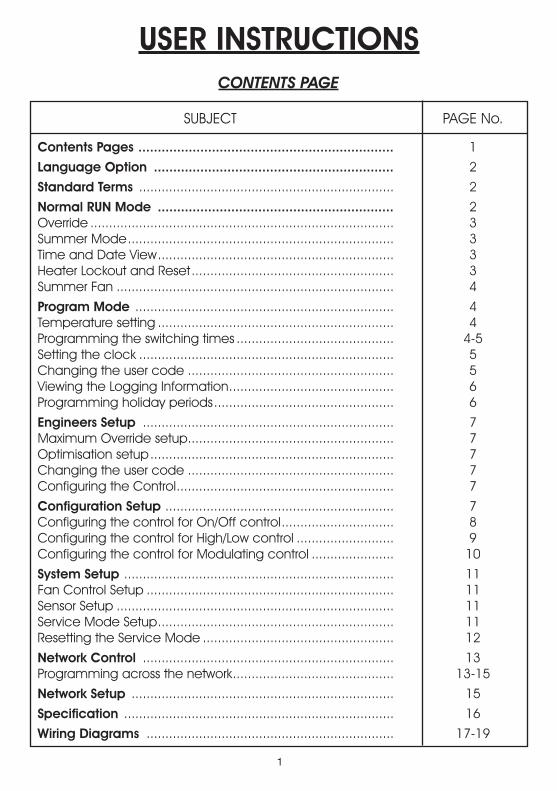
Contents Pages .................................................................. 1
Language Option .............................................................. 2
Standard Terms .................................................................... 2
Normal RUN Mode ............................................................. 2Override ................................................................................. 3Summer Mode ....................................................................... 3Time and Date View ............................................................... 3Heater Lockout and Reset ...................................................... 3Summer Fan .......................................................................... 4
Program Mode ..................................................................... 4Temperature setting ............................................................... 4Programming the switching times .......................................... 4-5Setting the clock .................................................................... 5Changing the user code ....................................................... 5Viewing the Logging Information ............................................ 6Programming holiday periods ................................................ 6
Engineers Setup ................................................................... 7Maximum Override setup ....................................................... 7Optimisation setup ................................................................. 7Changing the user code ....................................................... 7Configuring the Control .......................................................... 7
Configuration Setup ............................................................. 7Configuring the control for On/Off control .............................. 8Configuring the control for High/Low control .......................... 9Configuring the control for Modulating control ...................... 10
System Setup ........................................................................ 11Fan Control Setup .................................................................. 11Sensor Setup .......................................................................... 11Service Mode Setup ............................................................... 11Resetting the Service Mode ................................................... 12
Network Control ................................................................... 13Programming across the network ........................................... 13-15
Network Setup ...................................................................... 15
Specification ........................................................................ 16
Wiring Diagrams .................................................................. 17-19

2
Language Option
To select the required language press PROG and enter the code 2305 and press Enter. Then select the required language from the selection.
Standard Terms
Self Learning Optimisation is a system whereby the Heatmiser Control will automatically calculate the start up time to ensure the building is up to temperature for the programmed switching time. It does this by monitoring the internal temperature readings, so that for example, in milder weather conditions heat up times are reduced - thus saving energy.
Preheat is the number of hours the control can come on before the programmed switching time (when in optimising mode) This is setup under the Engineers code and can be set to no more than 8 hours.
Rate of Change is the time it takes to raise the building by 1.0°C. The factory default for this setting is 20 minutes but the control will automatically adjust this according to the fabric of the building.
Override Using the override button on the Heatmiser keypad allows the user to override the zone for a selected number of hours, to allow for unscheduled use of the system. A maximum can be set to stop users entering long override periods.
Switching period status: • Day is when the control is being controlled to an actual switching time (For example between 07.00
- 17.00 the control would be in a DAY condition) Outside of these hours the control would be in a night condition.
• Night is when no switching times have been programmed. At these times the control is set back to the night temperature.
Heater Lockout and Reset is standard on the Heatmiser Mistral and allows for a signal to be fed into the Heatmiser from the heater when the heater goes to lockout (overheat etc) Once the fault on the heater has been rectified a reset signal can be sent to the heater resetting lockout status.
Normal RUN Mode is when the control is operating normally and is not being programmed (ie showing the time and date screen). It is important to remember that when any alterations have been made to the Heatmiser’s program, the RUN button is pressed to return the control to the RUN mode.
Normal RUN Mode
There is one main Normal (Run) mode screen, and one Info screen on the Heatmiser IQ+. These are explained below;
On/Off RUN mode screen
This screen shows the time, actual temperature and the heat relay status (On or Off)
High/Low RUN mode screen
This screen shows the time, actual temperature and the heat status of both high and low flame
Pressing the Information button followed by option 1 will show the following display:
This display is shows the target temperature along with the switching period status.
FRI 07.58 23.0°CHEAT OFF
FRI 07.58 23.0°CLOW ON HIGH OFF
TARGET TEMP : 21.0°C TIME CLOCK: DAY

3
Override
The Heatmiser IQ+ can be overridden into a day or night condition to allow for any unscheduled operation of the system. The maximum time that the unit can be overridden will have been set by the installer.
To program an override period
• From the Normal RUN mode Press the Override button and enter your security code if required.
• Then choose 1) to enter the override mode
• Then select either 1 or 2 to override the zone ON(1) or OFF(2)
• You are now prompted to enter the length of the override period.
• Should the zone be above temperature, the control will show the following screen. Remember that the override function only overrides time and not temperature. This error message will also appear if the override time programmed exceeds the maximum override setting
• The status screen then indicates the zone has been put into an override condition.
To cancel an override period repeat the steps above, choosing 2 for OFF and then reduce the length of the override period to 00
Summer Mode
To enable the Summer mode facility press the Override/Summer button and select 2 for summer.
The control is then put in to the summer mode, which means that the temperature is controlled to the Night setback setting.
To cancel repeat the above operation.
Date
To display the current time and date: • Press INFO • Press 2 for date.• To cancel, repeat the above operation.
Heater Lockout/Reset
A supply can be wired into the Heatmiser from the heater lockout connection allowing for remote indication of a fault. Once the fault has been rectified on the heater, pressing RESET on the keypad sends a reset signal to the heater to clear the lockout status. This feature is highly beneficial on heaters installed out of reach.
Heater Reset (No lockout indication)
On heaters where there is no heater lockout, the Heatmiser can be used to send a reset signal.
To send a Reset signal in the case: • Press the Info/Reset button• Press 3 for Reset
The reset relay will be energised for a second.
Mon 13.06 20.0°CTime Clock: DAY
1> OVERRIDE MODE2> SUMMER MODE
OVERRIDE TO1> ON or 2> OFF
OVERRIDE SETTINGMAXIMUM (04) :03
** WARNING** INVALID DATA
Mon 13.06 20.0°CStatus: OVERRIDE
!
1>Override Mode2>Summer Mode
12.13.49SAT 11-12-02
1> INFORMATION 2>DATE3> LOCKOUT RESET
4
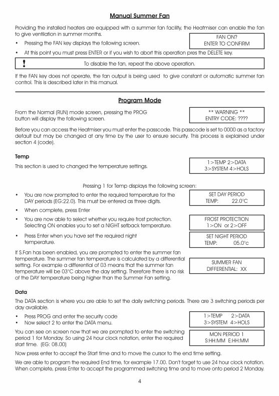
Manual Summer Fan
Providing the installed heaters are equipped with a summer fan facility, the Heatmiser can enable the fan to give ventilation in summer months.
• Pressing the FAN key displays the following screen.
• At this point you must press ENTER or if you wish to abort this operation pres the DELETE key.
To disable the fan, repeat the above operation.
If the FAN key does not operate, the fan output is being used to give constant or automatic summer fan control. This is described later in this manual.
Program Mode
From the Normal (RUN) mode screen, pressing the PROG button will display the following screen.
Before you can access the Heatmiser you must enter the passcode. This passcode is set to 0000 as a factory default but may be changed at any time by the user to ensure security. This process is explained under section 4 (code).
Temp
This section is used to changed the temperature settings.
Pressing 1 for Temp displays the following screen:
• You are now prompted to enter the required temperature for the DAY periods (EG:22.0). This must be entered as three digits.
• When complete, press Enter
• You are now able to select whether you require frost protection. Selecting ON enables you to set a NIGHT setback temperature.
• Press Enter when you have set the required night temperature.
If S.Fan has been enabled, you are prompted to enter the summer fantemperature. The summer fan temperature is calculated by a differentialsetting. For example a differential of 03 means that the summer fantemperature will be 03°C above the day setting. Therefore there is no riskof the DAY temperature being higher than the Summer Fan setting.
Data
The DATA section is where you are able to set the daily switching periods. There are 3 switching periods per day available.
• Press PROG and enter the security code • Now select 2 to enter the DATA menu.
You can see on screen now that we are prompted to enter the switching period 1 for Monday. So using 24 hour clock notation, enter the requiredstart time. (EG: 08.00)
Now press enter to accept the Start time and to move the cursor to the end time setting.
We are able to program the required End time, for example 17.00. Don’t forget to use 24 hour clock notation. When complete, press Enter to accept the programmed switching time and to move onto period 2 Monday.
FAN ON?ENTER TO CONFIRM
!
** WARNING **ENTRY CODE: ????
1>TEMP 2>DATA3>SYSTEM 4>HOLS
SET DAY PERIODTEMP: 22.0°C
FROST PROTECTION1>ON or 2>OFF
SET NIGHT PERIODTEMP: 05.0°c
1>TEMP 2>DATA3>SYSTEM 4>HOLS
MON PERIOD 1S:HH:MM E:HH:MM
SUMMER FANDIFFERENTIAL: XX
5
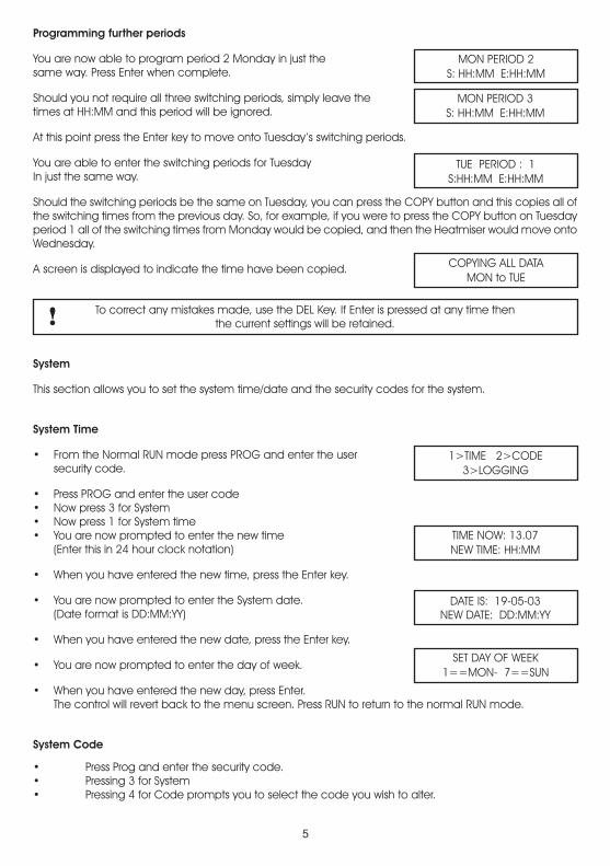
MON PERIOD 2S: HH:MM E:HH:MM
MON PERIOD 3S: HH:MM E:HH:MM
TUE PERIOD : 1S:HH:MM E:HH:MM
COPYING ALL DATAMON to TUE
!
Programming further periods You are now able to program period 2 Monday in just the same way. Press Enter when complete. Should you not require all three switching periods, simply leave thetimes at HH:MM and this period will be ignored. At this point press the Enter key to move onto Tuesday’s switching periods. You are able to enter the switching periods for Tuesday In just the same way. Should the switching periods be the same on Tuesday, you can press the COPY button and this copies all of the switching times from the previous day. So, for example, if you were to press the COPY button on Tuesday period 1 all of the switching times from Monday would be copied, and then the Heatmiser would move onto Wednesday. A screen is displayed to indicate the time have been copied.
To correct any mistakes made, use the DEL Key. If Enter is pressed at any time thenthe current settings will be retained.
System This section allows you to set the system time/date and the security codes for the system.
System Time • From the Normal RUN mode press PROG and enter the user security code. • Press PROG and enter the user code• Now press 3 for System • Now press 1 for System time • You are now prompted to enter the new time (Enter this in 24 hour clock notation) • When you have entered the new time, press the Enter key. • You are now prompted to enter the System date. (Date format is DD:MM:YY) • When you have entered the new date, press the Enter key. • You are now prompted to enter the day of week. • When you have entered the new day, press Enter. The control will revert back to the menu screen. Press RUN to return to the normal RUN mode.
System Code
• Press Prog and enter the security code.• Pressing 3 for System• Pressing 4 for Code prompts you to select the code you wish to alter.
1>TIME 2>CODE3>LOGGING
TIME NOW: 13.07NEW TIME: HH:MM
DATE IS: 19-05-03NEW DATE: DD:MM:YY
SET DAY OF WEEK1==MON- 7==SUN

6
1> Manager Code - This code gives access to all data settings. 2> Override Code - This code gives access to the Override and Summer functions.
To change the code, simply enter the new code when prompted. Press RUN to return to the Normal RUN mode.
Setting the Manager and Operators code to the same disables the Operators code.(ie. No code is required to access the operators section)
Logging
The Heatmiser IQ records hours run and temperature and burner history. Hours run is a weekly total and is stored for the previous 12 months. The temperature and burner history is recorded every 15 minutes and is also stored for 12 months.
Pressing 1 shows you this weeks hours run total. Pressing the left arrowallows you to scroll through the previous weeks. Using the right arrowallows you to scroll back up to the present date.
Pressing 2 shows you the last recorded temperature and burner status. Pressing the left arrow allows you to scroll through the records (15 minute intervals). Using the right arrow allows you to scroll back up to the last record.
Holidays
This is the section used to set the known holiday periods for the year when heating in the zone will not be required.
Five holiday periods can be set. Follow the steps below for instructions on how to set the holiday periods.
• Press the program key and select option 4. • You are now prompted to enter the holiday period 1. You must enter the start date in the DD-MM-YY format. When you have programmed the start date of the holiday press enter.
• You should now program the length of the holiday. You should calculate the number of days you want the heating off by counting from the first day of your holiday until the last. Now enter the length.
• When the first holiday period is set press the enter key.• Holiday period 2 will now be displayed.
You should program the remaining holiday periods in the same way. When all of the holiday periods have been programmed the control will revert back to the Data menu.
Important Note:1. If enter is pressed at any time then the current setting will be retained. 2. To cancel the holiday, put the date to 00.00.00 and length to 00. The holiday will then be cancelled.
1> MANAGER CODE2>OPERATORS CODE
CODE NOW: 0000NEW CODE:????
!
HOLIDAY PERIOD 1S:00-00-00 L:00
1> HOURS RUN2> TEMP & BURNER
7
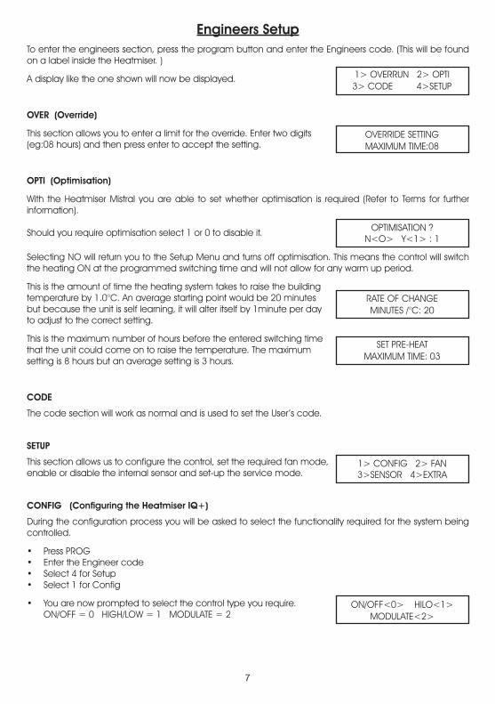
Engineers SetupTo enter the engineers section, press the program button and enter the Engineers code. (This will be found on a label inside the Heatmiser. )
A display like the one shown will now be displayed.
OVER (Override)
This section allows you to enter a limit for the override. Enter two digits(eg:08 hours) and then press enter to accept the setting.
OPTI (Optimisation)
With the Heatmiser Mistral you are able to set whether optimisation is required (Refer to Terms for further information). Should you require optimisation select 1 or 0 to disable it.
Selecting NO will return you to the Setup Menu and turns off optimisation. This means the control will switch the heating ON at the programmed switching time and will not allow for any warm up period.
This is the amount of time the heating system takes to raise the buildingtemperature by 1.0°C. An average starting point would be 20 minutesbut because the unit is self learning, it will alter itself by 1minute per dayto adjust to the correct setting.
This is the maximum number of hours before the entered switching timethat the unit could come on to raise the temperature. The maximumsetting is 8 hours but an average setting is 3 hours.
CODE
The code section will work as normal and is used to set the User’s code.
SETUP
This section allows us to configure the control, set the required fan mode,enable or disable the internal sensor and set-up the service mode.
CONFIG (Configuring the Heatmiser IQ+)
During the configuration process you will be asked to select the functionality required for the system being controlled.
• Press PROG• Enter the Engineer code• Select 4 for Setup• Select 1 for Config
• You are now prompted to select the control type you require. ON/OFF = 0 HIGH/LOW = 1 MODULATE = 2
1> OVERRUN 2> OPTI3> CODE 4>SETUP
OVERRIDE SETTINGMAXIMUM TIME:08
OPTIMISATION ?N<O> Y<1> : 1
RATE OF CHANGEMINUTES /°C: 20
SET PRE-HEATMAXIMUM TIME: 03
1> CONFIG 2> FAN3>SENSOR 4>EXTRA
ON/OFF<0> HILO<1>MODULATE<2>
8
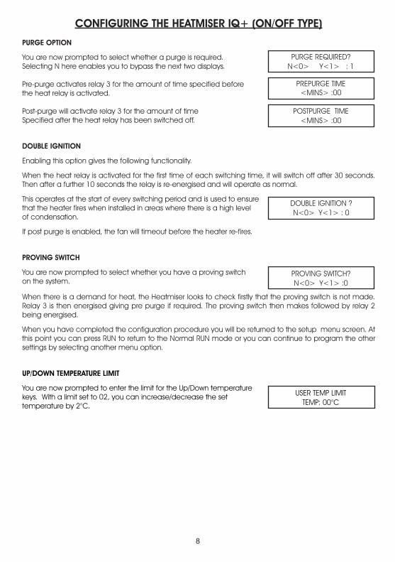
CONFIGURING THE HEATMISER IQ+ (ON/OFF TYPE)
PURGE OPTION
You are now prompted to select whether a purge is required. Selecting N here enables you to bypass the next two displays.
Pre-purge activates relay 3 for the amount of time specified beforethe heat relay is activated.
Post-purge will activate relay 3 for the amount of time Specified after the heat relay has been switched off.
DOUBLE IGNITION
Enabling this option gives the following functionality.
When the heat relay is activated for the first time of each switching time, it will switch off after 30 seconds. Then after a further 10 seconds the relay is re-energised and will operate as normal.
This operates at the start of every switching period and is used to ensurethat the heater fires when installed in areas where there is a high levelof condensation.
If post purge is enabled, the fan will timeout before the heater re-fires.
PROVING SWITCH
You are now prompted to select whether you have a proving switchon the system.
When there is a demand for heat, the Heatmiser looks to check firstly that the proving switch is not made. Relay 3 is then energised giving pre purge if required. The proving switch then makes followed by relay 2 being energised.
When you have completed the configuration procedure you will be returned to the setup menu screen. At this point you can press RUN to return to the Normal RUN mode or you can continue to program the other settings by selecting another menu option.
UP/DOWN TEMPERATURE LIMIT
You are now prompted to enter the limit for the Up/Down temperature keys. With a limit set to 02, you can increase/decrease the settemperature by 2°C.
PURGE REQUIRED?N<0> Y<1> : 1
PREPURGE TIME<MINS> :00
POSTPURGE TIME<MINS> :00
DOUBLE IGNITION ?N<0> Y<1> : 0
PROVING SWITCH?N<0> Y<1> :0
USER TEMP LIMITTEMP: 00°C
9
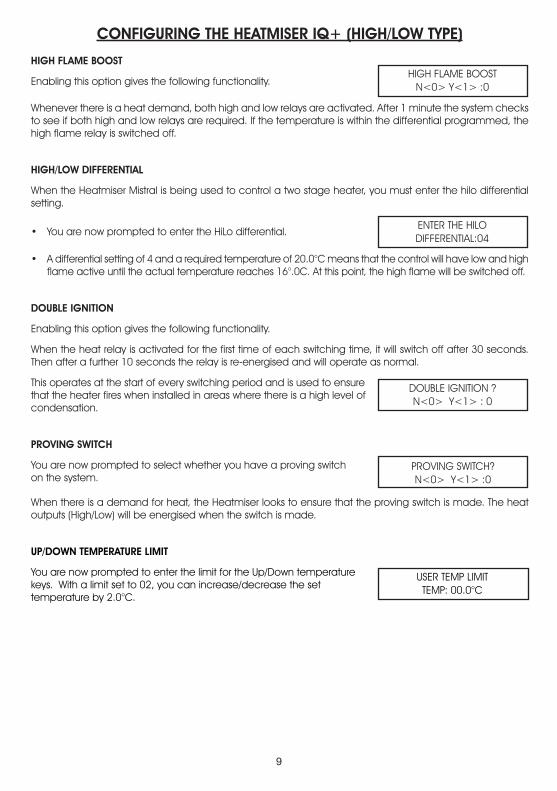
CONFIGURING THE HEATMISER IQ+ (HIGH/LOW TYPE)
HIGH FLAME BOOST
Enabling this option gives the following functionality. Whenever there is a heat demand, both high and low relays are activated. After 1 minute the system checks to see if both high and low relays are required. If the temperature is within the differential programmed, the high flame relay is switched off.
HIGH/LOW DIFFERENTIAL
When the Heatmiser Mistral is being used to control a two stage heater, you must enter the hilo differential setting.
• You are now prompted to enter the HiLo differential. • A differential setting of 4 and a required temperature of 20.0°C means that the control will have low and high
flame active until the actual temperature reaches 16°.0C. At this point, the high flame will be switched off.
DOUBLE IGNITION
Enabling this option gives the following functionality.
When the heat relay is activated for the first time of each switching time, it will switch off after 30 seconds. Then after a further 10 seconds the relay is re-energised and will operate as normal.
This operates at the start of every switching period and is used to ensurethat the heater fires when installed in areas where there is a high level ofcondensation.
PROVING SWITCH
You are now prompted to select whether you have a proving switchon the system.
When there is a demand for heat, the Heatmiser looks to ensure that the proving switch is made. The heat outputs (High/Low) will be energised when the switch is made.
UP/DOWN TEMPERATURE LIMIT
You are now prompted to enter the limit for the Up/Down temperature keys. With a limit set to 02, you can increase/decrease the settemperature by 2.0°C.
HIGH FLAME BOOSTN<0> Y<1> :0
ENTER THE HILODIFFERENTIAL:04
DOUBLE IGNITION ?N<0> Y<1> : 0
PROVING SWITCH?N<0> Y<1> :0
USER TEMP LIMITTEMP: 00.0°C

10
CONFIGURING THE HEATMISER IQ+ (MODULATE TYPE)
In modulation mode, you can set the temperature band where the control will modulate the from 10v to 0v. The heat output remains active.
You are now prompted to enter the differential setting With a differential of 02, the Mistral will start to modulate 2°C degrees below the set temperature.
You are now prompted to select whether a purge is required Selecting N here enables you to bypass the next two displays
Pre purge activates relay 3 for the amount of time specified before the heat relay is activated.
Post purge will activate relay 3 for the amount of time specified before the heat relay is activated.
DOUBLE IGNITION
Enabling this option gives the following functionality.When the heat relay is activated for the first time of each switching time, it will switch off after 30 seconds. Then after a further 10 seconds the relay is re-energised and will operate as normal.
This operates at the start of every switching period and is used to ensure that the heater fires when installed in areas where there is a high level of condensation.
If post purge is enabled, the fan will timeout before the heater re-fires.
PROVING SWITCH
You are now prompted to select whether you have a proving switch on the system.
When there is a demand for heat, the Heatmiser looks to check firstly that the proving switch is not made. Relay 3 is then energised giving pre-purge if required. The proving switch then makes followed by relay 2 being energised.
When you have completed the configuration procedure you will be returned to the setup menu screen. At this point you can press RUN to return to the Normal RUN mode or you can continue to program the other settings by selecting another menu option.
UP/DOWN TEMPERATURE LIMIT
You are now prompted to enter the limit for the Up/Down temperature keys. With a limit set to 02, you can increase/decrease the settemperature by 2°C
ENTER MODULATIONDIFFERENCE: 04
PURGE REQUIREDN<0> Y<1> : 1
PREPURGE TIME<MINS> : 00
POST PURGE TIME<MINS> :00
DOUBLE IGNITIONN<0> Y<1> :0
PROVING SWITCH?N<0> Y<1> :0
USER TEMP LIMITTEMP: 00°C
11
INTERNAL SENSORN<0> Y<1> : 0
CALIBRATE (20)INTERNAL : 23.0
CALIBRATE (19)REMOTE 1 : 20.0
SERVICE MODEN<0> Y<1> : 0
SERVICE MODEHOURS RUN: 0000
SERVICE MODECALL : 0000000000
USER<0> C.FAN <1>S.FAN <2> : 0
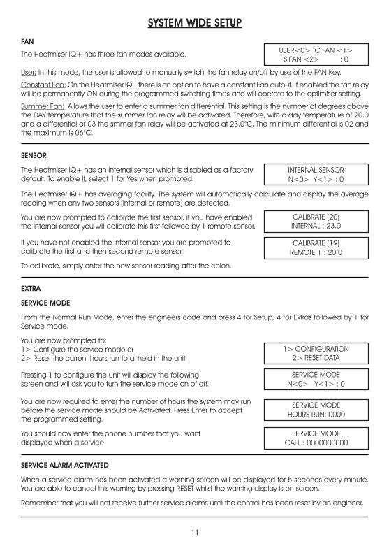
SYSTEM WIDE SETUP
FAN The Heatmiser IQ+ has three fan modes available.
User: In this mode, the user is allowed to manually switch the fan relay on/off by use of the FAN Key.
Constant Fan: On the Heatmiser IQ+there is an option to have a constant Fan output. If enabled the fan relay will be permanently ON during the programmed switching times and will operate to the optimiser setting.
Summer Fan: Allows the user to enter a summer fan differential. This setting is the number of degrees above the DAY temperature that the summer fan relay will be activated. Therefore, with a day temperature of 20.0 and a differential of 03 the smmer fan relay will be activated at 23.0°C. The minimum differential is 02 and the maximum is 06°C.
SENSOR
The Heatmiser IQ+ has an internal sensor which is disabled as a factorydefault. To enable it, select 1 for Yes when prompted.
The Heatmiser IQ+ has averaging facility. The system will automatically calculate and display the average reading when any two sensors (internal or remote) are detected.
You are now prompted to calibrate the first sensor, if you have enabledthe internal sensor you will calibrate this first followed by 1 remote sensor.
If you have not enabled the internal sensor you are prompted tocalibrate the first and then second remote sensor.
To calibrate, simply enter the new sensor reading after the colon.
EXTRA
SERVICE MODE
From the Normal Run Mode, enter the engineers code and press 4 for Setup, 4 for Extras followed by 1 for Service mode.
You are now prompted to: 1> Configure the service mode or 2> Reset the current hours run total held in the unit
Pressing 1 to configure the unit will display the following screen and will ask you to turn the service mode on of off.
You are now required to enter the number of hours the system may runbefore the service mode should be Activated. Press Enter to acceptthe programmed setting.
You should now enter the phone number that you want displayed when a service
SERVICE ALARM ACTIVATED
When a service alarm has been activated a warning screen will be displayed for 5 seconds every minute. You are able to cancel this warning by pressing RESET whilst the warning display is on screen.
Remember that you will not receive further service alarms until the control has been reset by an engineer.
1> CONFIGURATION2> RESET DATA

12
RESETTING THE SERVICE ALARM
After a service alarm has been activated you are able to reset the hours setting without the need to reprogram the telephone number by selecting Reset from the Configuration/Reset screen.
SYSTEM RESET
This function resets the Heatmiser Mistral’s settings back to the factory default.
To put the control through a reset:• Press 4 for Setup • Press 4 for Extra • Press 2 for Reset
• Pressing ENTER at this point will erase all data. To abort press the DELETE Key.
RESET ALL DATA?ENTER TO CONFIRM

“1 USE LOCAL DATA”“2 USE NW DATA ”
1)TEMP 2)DATA3)SYSTEM 4)HOLS
HEATMISER IQ+
Network User Section
System explanation:
• Up to 30 IQ+s can be connected together to allow for central control of the heating system.• The communication link is only used when copying/viewing data from a networked IQ+. This means that
should the communication link fail, the heating system will continue to work as normal.• The design of the IQ+ network systems means that there is no “Master keypad” Each IQ+ can be setup
to allow full network access, only local access or no access at all (keypad locked)• Only 1 IQ+ can be programmed over the network at any one time.
Operating Normal RUN Mode functions on a networked IQ+
Normal RUN mode functions are:
1. Fan2. Override3. Summer mode4. View set-point and time-clock status5. View current time and date6. Reset a lockout status
• Use the left/right arrow keys to scroll around the network. The title of each IQ+ will be displayed as you scroll the network.
• Press Prog• The display will inform the user that the control is entering REMOTE MODE• The user can now perform any Normal Run mode operation as described on pages 2-4 of this
manual
NB: In Normal Run mode, the following applies. After 4 minutes of inactivity, the remote connection will time-out. You can disconnect from the networked IQ+ by pressing the PROG key. To close the network connection,
press RUN.
Programming a networked IQ+
To begin programming a networked IQ+, follow the steps below;
• Press Program and enter the “Network Access Code”. The network code can be found on the data label in the product.
• You are now presented with two options.
Use Local Data: You should use this option if you want to program the local IQ+ and want the ability to copy the data to a networked IQ+.
You are now prompted with this menu.
13

1) TEMP
This section is used to change the temperature settings.
• You are now prompted to enter the required temperature for the DAY period (EG:22.0) This must be entered as three digits.
• When complete, press Enter Selecting ON enables you to set a NIGHT setback temperature.
• Press Enter when you have set the required night temperature.
• If S.FAN has been enabled, you are prompted to enter temperature. The summer fan temperature is calculated by a differential setting. For example a differential of 03 means that the summer fan temperature will be 03°C above the DAY setting. Therefore there is no risk of the DAY temperature being higher than the FAN setting.
2) DATA
This section is where you are able to set the daily switching periods. There are 3 switching periods per day available.
When you select DATA, you are presented with an additional screen over the standard programming mode. This screen gives you the ability to copy the switching time data to other IQ+s on thenetwork. Select 1 to program the switching times.Select 2 to begin copying the times
When you press 2 for Copy,you are prompted with this screen.
1> Zone. This allows you to select a zone by using the left/right arrow keys. When you have selected the zone you wish to copy the times to, press Copy
2> All. Selecting this allows you to copy the times to all IQ+s on the network.
3) SYSTEM
This section allows you to set the system Time/Date and the security codes for the system.
System Time• From the Normal RUN mode press PROG and enter the user
security code • Press Prog and enter the user code• Now press 3 for System • Now press 1 for System time • You are now prompted to enter the new time
(Enter this in 24hr clock notation)• When you have entered the new time, press the Enter key• You are now prompted to enter the new date, press the Enter key • When you have entered the new date, press the Enter key• You are now prompted to enter the day of the week. • When you have entered the new day, press Enter
The control will revert back to the menu screen.Press Run to return to the normal RUN mode.
SET DAY PERIODTEMP: 22.0°C
FROST PROTECTION1> ON or 2>OFF
SET NIGHT PERIODTEMP: 05.0°C
SUMMER FANDIFFERENTIAL: XX
“SWITCH TIMES”1>SET 2>COPY
“COPY TIMES”1>ZONE 2>ALL
14
1>SYSTEM TIME2>SYSTEM CODE
TIME NOW: 13.07NEW TIME: HH:MM
DATE IS: 19-05-04NEW DATE:DD:MM:YY
SET DAY OF WEEK1=Mon 7=Sun

System Code
• Press Prog and enter the security code• Pressing 3 for System• Pressing 4 for Code prompts you to select the code you wish to alter
1>Manager - This code gives access to all data settings2>Operator - This code gives access to Override, Fan, Summer functions.
4) HOLS
When you select HOLS, you are presented with an additional screenover the standard programming mode. This screen gives you theability to copy holiday periods to other IQ+s on the network. Select 1 to program the holiday periods.Select 2 to begin copying the holidays
When you press 2 for Copy, you are prompted with this screen.
1> Zone. This allows you to select a zone by using the left/right arrow keys. When you have selected the zone you wish to copy the Hols to, press Copy
2> All. Selecting this allows you to copy the times to all IQ+s on the network.
Use NW Data: This allows the user to select and program a networked IQ+.Under this mode you cannot program the Local IQ+ and the global copy function will not copy the data to the Local IQ+.
• Pressing the Back and Forward arrows keys will display the name of the IQ+s available on the system.
• When you have identified the IQ+ you wish to program, wait 5 seconds and the IQ+ will automatically display the following display.
• Follow the instructions on 2-3 for programming details in this mode.
Network Setup Section
In order to setup the IQ+ on the network, follow the steps outlined below.You should repeat these steps for each IQ+ on the network.
Important: Setup outstation 1 last.
• Press Program and enter the network setup code. (The network setup code can be found on the data label inside the product)
• You are now prompted to enter the station number. You should enter a two digit number for each IQ+ on the network. One IQ+ must be given the ID number 01
• You are now prompted to enter a title for this IQ+. You are able to set a title up-to 11 characters long. Enter the title by using the alphabet keys to select the required letter, and enter to accept.
“HOLIDAYS”1>SET 2>COPY
“COPY HOLS”1>ZONE 2>ALL
“!SELECT CONTROL!”“ BACK FWD “
“1>TEMP DATA”“3>SYSTEM HOLS”
“ ** WARNING **”“ENTRY CODE:????”
“NETWORK ID NO ”“FOR THIS UNIT: XX”
“CONTROL NAME?”“XXXXXXXXXXX “
15

• You are now prompted to select whether you require “Local” “Lock” or “Full” access.
“Local” = This means that the IQ+ can be used locally, but cannot be used to access other IQ+s on the network.“Lock” = This means that the IQ+ will be locked and cannot be used“Full” = This means that the IQ+ can be used locally, and can also be used to access other IQ+s on the network.
• You are now prompted to select whether you want to give “Remote Reset” facility. If enabled, the user will be notified when any heater goes to lockout. This information will be displayed on the IQ+s that have been setup to offer “full” access. The user will also be able to send a reset signal via the network to reset the heater which is at lockout.
Setting up Station 1 (You should do this last)
• You will be prompted to enter a Network code when setting up Outstation 1. This is a 4 digit code that you will be able to use to gain access to all the other IQ+s on the network. When you enter this code, it will be sent to all IQ+s on the system.
• You will be prompted to enter the number of controls on the system.
“ACCESS? LOCAL<0>”“LOCK<1> FULL<2> “
”ALLOW REMOTE RESET?”“ N<0> Y<1> :0 “
“SET NETWORK CODE”“ XXXX “
“ENTER NUM OF CTL”“1 TO 30: “
Enclosure: ABS Fire Retardant
Dimensions: 222mm x 156mm x 61mm (Length, Height,Depth)
Weight: 1.3 kg
Relays: Relay 1-3 normally open contacts Relay 4 normally open, normally closed contacts 10 amp 230v rating relays 1-3
Alarm Input: 230v AC. 5mA Max.
Supply: 230v AC ± 10% 50Hz
Sensors: Only use Heatmiser Sensors. Twin screened cable (Beldon 8451)
Battery: 3 years (Replacement battery: CR2430)
Fuses: FS1: 800mA Antisurge FS2: 500mA Quick blow FS3: 500mA Quick blow
SYSTEM SPECIFICATIONS
16

17
IQ+ ON_OFF RADIANT HEATER
IQ+ ON/OFF WARM AIR HEATER
18
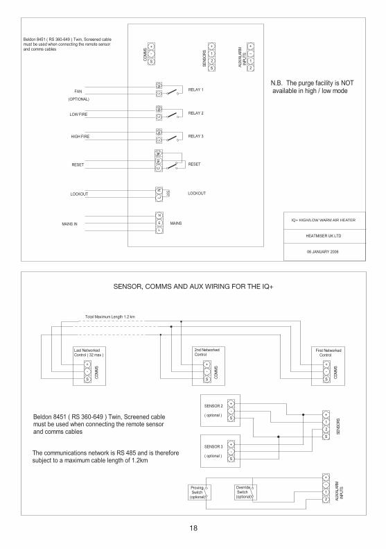
IQ+ HIGH/LOW WARM AIR HEATER
SENSOR, COMMS AND AUX WIRING FOR THE IQ+
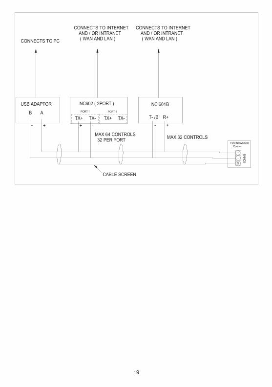
19