user guide 1 8 din universal process indicator€¦ · · 2015-04-271/8 din universal process...
TRANSCRIPT
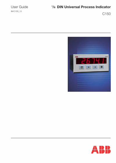
1/8 DIN Universal Process Indicator
C150
User GuideIM/C150_13

Information in this manual is intended only to assist our customers in the efficient operationof our equipment. Use of this manual for any other purpose is specifically prohibited and itscontents are not to be reproduced in full or part without prior approval of the TechnicalPublications Department.
Health and Safety
To ensure that our products are safe and without risk to health, the following pointsmust be noted:
1. The relevant sections of these instructions must be read carefully beforeproceeding.
2. Warning labels on containers and packages must be observed.
3. Installation, operation, maintenance and servicing must only be carried out bysuitably trained personnel and in accordance with the information given.
4. Normal safety precautions must be taken to avoid the possibility of an accidentoccurring when operating in conditions of high pressure and/or temperature.
5. Chemicals must be stored away from heat, protected from temperature extremesand powders kept dry. Normal safe handling procedures must be used.
6. When disposing of chemicals ensure that no two chemicals are mixed.
Safety advice concerning the use of the equipment described in this manual or anyrelevant hazard data sheets (where applicable) may be obtained from the Companyaddress on the back cover, together with servicing and spares information.
Warning – Refer to the manualfor instructions
Caution – Risk of electric shock
Protective earth (ground) terminal
Earth (ground) terminal
Direct current supply only
Alternating current supply only
Both direct and alternatingcurrent supply
The equipment is protectedthrough double insulation
Electrical SafetyThis equipment complies with the requirements of BS EN 61010-1:2001-2 "SafetyRequirements for Electrical Equipment for Measurement, Control and Laboratory Use". Ifthe equipment is used in a manner NOT specified by the Company, the protection providedby the equipment may be impaired.
SymbolsOne or more of the following symbols may appear on the equipment labelling:
1
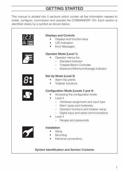
Displays and Controls• Displays and function keys• LED Indication• Error Messages
Operator Mode (Level 1)• Operator menus for:
– Standard Indicator– Totalizer/Batch Controller– Maximum/Minimum/Average Indicator
Set Up Mode (Level 2)• Alarm trip points• Totalizer functions
Configuration Mode (Levels 3 and 4)• Accessing the configuration levels• Level 3
– Hardware assignment and input type– Alarm types and hysteresis– Operator functions and totalizer setup– Digital input and serial communications
• Level 4– Ranges and passwords
Installation• Siting• Mounting• Electrical connections
8
GETTING STARTED
This manual is divided into 5 sections which contain all the information needed toinstall, configure, commission and operate the COMMANDER 150. Each section isidentified clearly by a symbol as shown below.
Symbol Identification and Section Contents

2
CONTENTS
GETTING STARTED ............................................................................................... 1
1 DISPLAYS AND FUNCTION KEYS .................................................................. 31.1 Introduction ............................................................................................... 31.2 Use of Function Keys ................................................................................. 41.3 LED Alarms and Indicators ........................................................................ 51.4 Error Messages ......................................................................................... 6
2 OPERATOR MODE ........................................................................................... 72.1 Introduction ............................................................................................... 72.2 Operating Page – Standard (Level 1) ......................................................... 82.3 Operating Page – Totalizer (Level 1) .......................................................... 92.4 Operating Page – Maths Functions (Level 1) ........................................... 11
3 SET UP MODE ............................................................................................... 133.1 Introduction ............................................................................................. 133.2 Setup Level (Level 2) .............................................................................. 14
4 CONFIGURATION MODE ............................................................................... 184.1 Introduction ............................................................................................. 184.2 Accessing the Configuration Mode .......................................................... 184.3 Basic Hardware and Configuration (Level 3) ............................................ 20
4.3.1 Hardware Assignment and Input Type ........................................ 204.3.2 Alarms ....................................................................................... 224.3.3 Operator Functions and Totalizer Set Up .................................... 244.3.4 Digital Input and Serial Communications .................................... 26
4.4 Ranges and Passwords (Level 4) ............................................................ 28
5 INSTALLATION .............................................................................................. 315.1 Siting ....................................................................................................... 325.2 Mounting ..................................................................................................345.3 Electrical Connections ............................................................................ 365.4 Relays, Arc Suppression, Inputs and Outputs ........................................ 38
5.4.1 Relay Contact Ratings ............................................................... 385.4.2 Arc Suppression ........................................................................ 385.4.3 Logic Output .............................................................................. 385.4.4 Retransmission Analog Output ................................................... 385.4.5 Digital Input ................................................................................ 38
SPECIFICATION ................................................................................................... 39
3
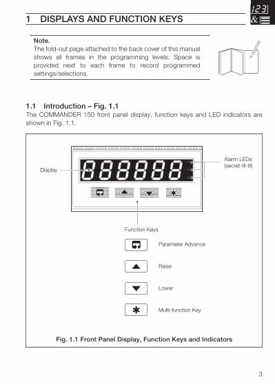
888888A1
A2
A3
Alarm LEDs(secret-til-lit)
Display
Function Keys
Parameter Advance
Raise
Lower
Multi-function Key
1 DISPLAYS AND FUNCTION KEYS
Note.The fold-out page attached to the back cover of this manualshows all frames in the programming levels. Space isprovided next to each frame to record programmedsettings/selections.
1.1 Introduction – Fig. 1.1The COMMANDER 150 front panel display, function keys and LED indicators areshown in Fig. 1.1.
Fig. 1.1 Front Panel Display, Function Keys and Indicators

4
A – Raise and Lower Keys
B – Parameter Advance Key
Frame 1(top of level)
Frame 2
+
–
C – Multi-function Key
Use to change/set a parameter value…
Use to advance to the nextframe within a level…
or…
100.0 100.1
99.9
LEVEL1
100.1
CodE
0
Use to view a parameter setting or selection…
123456
…select individual characters in a frame
or…
…move between levels
LEVEL1
LEVEL2
LEVELx 100.1 200.2 300.3 400.4
Press andhold
or…
…select the top (LEVEL) framefrom within a level
Note. This key also stores any changes made in the previous frame
…1 DISPLAYS AND FUNCTION KEYS
1.2 Use of Function Keys – Fig. 1.2
Fig. 1.2 Use of Function Keys
5
Alarm 1
COMMANDER 150
Alarm 2
Alarm 3
Alarm LEDs
A1
A2
A3
1 DISPLAYS AND FUNCTION KEYS…
1.3 LED Alarms and Indicators
LED Status
All Flashing
• Indicator is in the configuration mode – see Section 4.2.
A1, A2 and A3• Flashes when Alarm is active (off when inactive).
• Lit constantly when Alarm 1 is an active latched alarm which hasbeen acknowledged
Fig. 1.3 LED Alarms and Indicators
6
…1 DISPLAYS AND FUNCTION KEYS
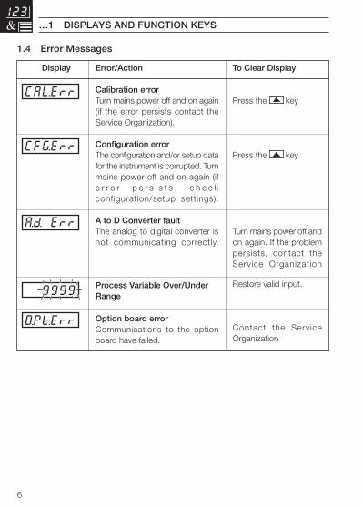
1.4 Error Messages
Error/Action
Calibration errorTurn mains power off and on again(if the error persists contact theService Organization).
Configuration errorThe configuration and/or setup datafor the instrument is corrupted. Turnmains power off and on again (ife r r o r p e r s i s t s , c h e c kconfiguration/setup settings).
A to D Converter faultThe analog to digital converter isnot communicating correctly.
Process Variable Over/UnderRange
Option board errorCommunications to the optionboard have failed.
Display To Clear Display
Press the key
Press the key
Turn mains power off andon again. If the problempersists, contact theService Organization
Restore valid input.
Contact the ServiceOrganization
9999
CAL.Err
CFG.Err
A.d. Err
DPt.Err
7
2 OPERATOR MODE
2.1 IntroductionOperator Mode (Level 1) is the normal day-to-day mode of the COMMANDER 150.
Frames displayed in level 1 are determined by the indicator functions which areselected during configuration of the instrument – see Section 4.
Note. Only the operating frames relevant to the configured functions aredisplayed in Operator Mode.
The three indicator functions are:
• Standard Indicator – page 8
• Indicator with Totalization – page 9
• Indicator with Max./Min./Average – page 11
8
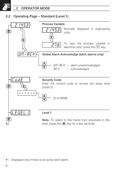
------
CodE
2145.3
UN-ACK
LEVEL1
•1
27.6
2145.3
…2 OPERATOR MODE
2.2 Operating Page – Standard (Level 1)
•1 Displayed only if there is an active latch alarm.
Process Variable
Normally displayed in engineeringunits.
To view the process variable inelectrical units, press the key.
Global Alarm Acknowledge (latch alarms only)
UN-ACK. – alarm unacknowledgedACK. – acknowledged
Security CodeEnter the correct code to access the setup level(Level 2).
[0 to 9999]
Level 1
Note. To select to this frame from anywhere in thislevel, press the key for a few seconds.
9
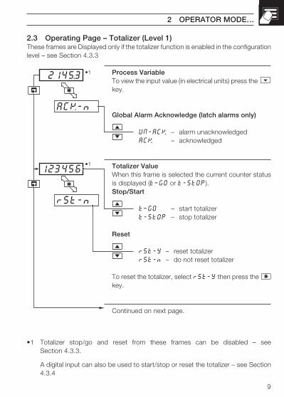
rSt-n
2145.3
ACK-n
123456
•1
•1
2 OPERATOR MODE…
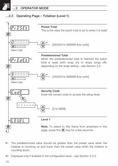
2.3 Operating Page – Totalizer (Level 1)These frames are Displayed only if the totalizer function is enabled in the configurationlevel – see Section 4.3.3
•1 Totalizer stop/go and reset from these frames can be disabled – seeSection 4.3.3.
A digital input can also be used to start/stop or reset the totalizer – see Section4.3.4
Process VariableTo view the input value (in electrical units) press the key.
Global Alarm Acknowledge (latch alarms only)
UN-ACK. – alarm unacknowledgedACK. – acknowledged
Totalizer ValueWhen this frame is selected the current counter statusis displayed (t–GO or t-StOP).Stop/Start
t–GO – start totalizert-StOP – stop totalizer
Reset
rSt-Y – reset totalizerrSt-n – do not reset totalizer
To reset the totalizer, select rSt-Y then press the key.
Continued on next page.
10
999999
PrESEt
000000
PrEdEt
------
CodE
•1
•2
•1
Select Digit
Select Digit
LEVEL
…2 OPERATOR MODE
…2.3 Operating Page – Totalizer (Level 1)
•1 The predetermined value should be greater than the preset value when thetotalizer is counting up and lower than the preset value when the totalizer iscounting down.
•2 Displayed only if enabled in the configuration level – see Section 4.3.3.
Preset TotalThis is the value the batch total is set to when it is reset
[000000 to 999999 flow units]
Predetermined TotalWhen the predetermined total is reached the batchtotal is reset (with wrap on) or stops (wrap off),depending on the wrap setting – see Section 3.2.
[000000 to 999999 flow units]
Security CodeEnter the correct code to access the setup level.
[0 to 9999]
Level 1
Note. To select to this frame from anywhere in thispage, press the key for a few seconds.
11
rSt-n
2145.3
UN-ACK
A 140.5
H150.2
•1
2 OPERATOR MODE…
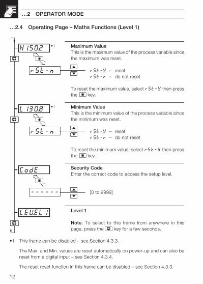
•1 This frame can be disabled – see Section 4.3.3.
The average value is reset automatically on power-up and can also be reset froma digital input – see Section 4.3.4.
The reset function in this frame can be disabled – see Section 4.3.3.
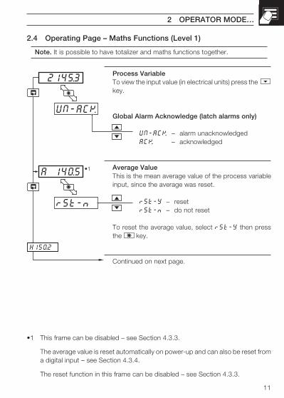
Process VariableTo view the input value (in electrical units) press the key.
Global Alarm Acknowledge (latch alarms only)
UN-ACK. – alarm unacknowledgedACK. – acknowledged
Average ValueThis is the mean average value of the process variableinput, since the average was reset.
rSt-Y – resetrSt-n – do not reset
To reset the average value, select rSt-Y then pressthe key.
Continued on next page.
2.4 Operating Page – Maths Functions (Level 1)
Note. It is possible to have totalizer and maths functions together.
12
------
rSt-n
H150.2
rSt-n
L130.8
CodE
•1
•1
LEVEL1
…2 OPERATOR MODE
…2.4 Operating Page – Maths Functions (Level 1)
•1 This frame can be disabled – see Section 4.3.3.
The Max. and Min. values are reset automatically on power-up and can also bereset from a digital input – see Section 4.3.4.
The reset reset function in this frame can be disabled – see Section 4.3.3.
Maximum ValueThis is the maximum value of the process variable sincethe maximum was reset.
rSt-Y – resetrSt-n – do not reset
To reset the maximum value, select rSt-Y then pressthe key.
Minimum ValueThis is the minimum value of the process variable sincethe minimum was reset.
rSt-Y – resetrSt-n – do not reset
To reset the minimum value, select rSt-Y then pressthe key.
Security CodeEnter the correct code to access the setup level.
[0 to 9999]
Level 1
Note. To select to this frame from anywhere in thispage, press the key for a few seconds.
13
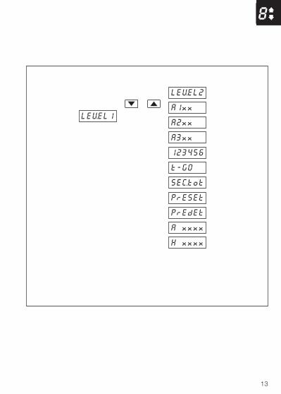
8
LEVEL1
LEVEL2
A1xx
A2xx
A3xx
123456
t-GO
SEC.tot
PrESEt
PrEdEt
A xxxx
H xxxx
L xxxx
0AdJ
Level 2 – Set Up
Alarm 1 Trip Point
Alarm 2 Trip Point
Alarm 3 Trip Point
Batch Total
Totalizer Stop/Go
Secure Total/Reset
Preset Batch Total
Predetermined BatchTotal
Average Value
Maximum Value
Minimum Value
Offset Adjustment
SecurityCode
Level 1 –Operating Level
CorrectPassword
CodE x
3 SET UP MODE
Fig. 3.1 Accessing the Setup Level (Level 2)
3.1 IntroductionTo access the Setup Level (Level 2) the correct password must be entered in thesecurity code frame (CodE) in Level 1– see Fig. 3.1.
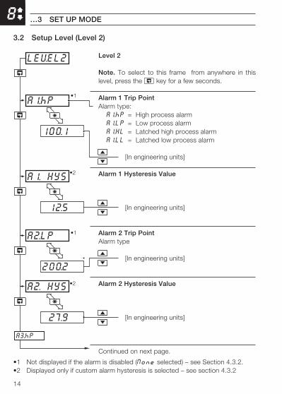
14
8
200.2
A1.hP
100.1
A2.LP
LEVEL2
•1
•1
A1. HYS
12.5
A2. HYS
27.9
A3.hP
•2
•2
…3 SET UP MODE
3.2 Setup Level (Level 2)
Level 2
Note. To select to this frame from anywhere in thislevel, press the key for a few seconds.
Alarm 1 Trip PointAlarm type:A1.hP = High process alarmA1.LP = Low process alarmA1.HL = Latched high process alarmA1.LL = Latched low process alarm
[In engineering units]
Alarm 1 Hysteresis Value
[In engineering units]
Alarm 2 Trip PointAlarm type
[In engineering units]
Alarm 2 Hysteresis Value
[In engineering units]
Continued on next page.
•1 Not displayed if the alarm is disabled (None selected) – see Section 4.3.2.•2 Displayed only if custom alarm hysteresis is selected – see section 4.3.2
15
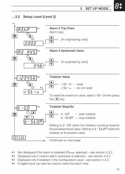
8
300.3
A3.hP •1
t-StOP
123456
rSt-n
t-GO
SEC.tOt
•3
•3
•4
34.6
A3 HYS •2
3 SET UP MODE…
…3.2 Setup Level (Level 2)
•1 Not displayed if the alarm is disabled (None selected) – see section 4.3.2•2 Displayed only if custom alarm hysteresis is selected – see section 4.3.2•3 Displayed only if enabled in the Configuration Level – see section 4.3.3•4 A digital input can also be used to reset the batch total.
Alarm 3 Trip PointAlarm type
[In engineering units]
Alarm 3 Hysteresis Value
[In engineering units]
Totalizer Value
rSt-Y – resetrSt-n – do not reset
To reset the maximum value, select rSt-Y then pressthe key.
Totalizer Stop/Go
t-GO – start totalizert-StOP – stop totalizer
Setting to t-GO starts the totalizer counting towardsthe predetermined value. Setting to t-StOP holds thetotalizer at its present value.
Continued on next page
16
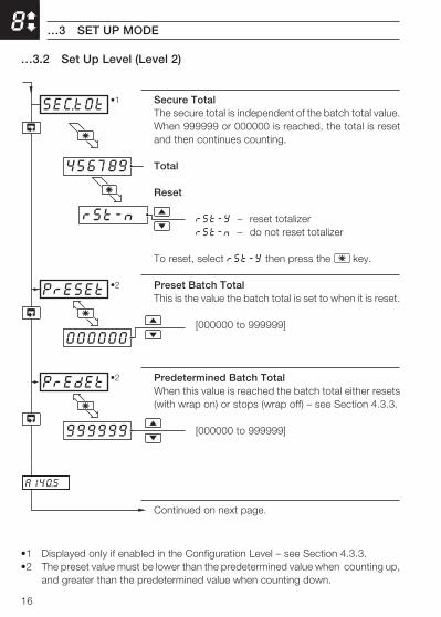
8
PrESEt
000000
A140.5
PrEdEt
999999
•2
•2
456789
SEC.tOt
rSt-n
•1
…3 SET UP MODE
…3.2 Set Up Level (Level 2)
•1 Displayed only if enabled in the Configuration Level – see Section 4.3.3.•2 The preset value must be lower than the predetermined value when counting up,
and greater than the predetermined value when counting down.
Secure TotalThe secure total is independent of the batch total value.When 999999 or 000000 is reached, the total is resetand then continues counting.
Total
Reset
rSt-Y – reset totalizerrSt-n – do not reset totalizer
To reset, select rSt-Y then press the key.
Preset Batch TotalThis is the value the batch total is set to when it is reset.
[000000 to 999999]
Predetermined Batch TotalWhen this value is reached the batch total either resets(with wrap on) or stops (wrap off) – see Section 4.3.3.
[000000 to 999999]
Continued on next page.
17
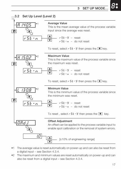
8
H150.2
rSt-n
L130.8
rSt-n
O.AdJ
1.0
•2
•2
A140.5
rSt-n
•1
3 SET UP MODE…
…3.2 Set Up Level (Level 2)
•1 The average value is reset automatically on power-up and can also be reset froma digital input – see Section 4.3.4.
•2 The maximum and minimum values are reset automatically on power-up and canalso be reset from a digital input – see Section 4.3.4.
Average ValueThis is the mean average value of the process variableinput since the average was reset.
rSt-Y – resetrSt-n – do not reset
To reset, select rSt-Y then press the key.
Maximum ValueThis is the maximum value of the process variable sincethe maximum was reset.
rSt-Y – resetrSt-n – do not reset
To reset, select rSt-Y then press the key.
Minimum ValueThis is the minimum value of the process variable sincethe minimum was reset.
rSt-Y – resetrSt-n – do not reset
To reset , select rSt-Y then press the key.
Offset AdjustmentAn offset can be applied to the process variable input toenable spot calibration or the removal of system errors.
[±10% of engineering range]
18
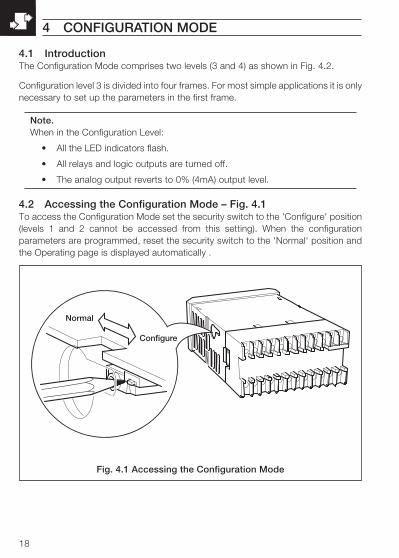
Normal
Configure
4 CONFIGURATION MODE
Fig. 4.1 Accessing the Configuration Mode
4.1 IntroductionThe Configuration Mode comprises two levels (3 and 4) as shown in Fig. 4.2.
Configuration level 3 is divided into four frames. For most simple applications it is onlynecessary to set up the parameters in the first frame.
Note.When in the Configuration Level:
• All the LED indicators flash.
• All relays and logic outputs are turned off.
• The analog output reverts to 0% (4mA) output level.
4.2 Accessing the Configuration Mode – Fig. 4.1To access the Configuration Mode set the security switch to the 'Configure' position(levels 1 and 2 cannot be accessed from this setting). When the configurationparameters are programmed, reset the security switch to the 'Normal' position andthe Operating page is displayed automatically .
19
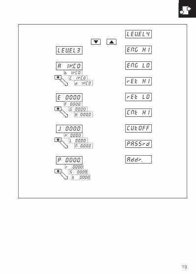
E 0000
b 1KC0
C 1KC0
d 1KC0
LEVEL3
LEVEL4
ENG HI
ENG LO
rEt HI
rEt LO
A 1KC0
K 0000
L 0000
N 0000
r 0000
S 0000
t 0000
F 0000
G 0000
H 0000
J 0000
P 0000
CNt HI
CUtOFF
PASSrd
Addr.
Level 4
EngineeringRange High
EngineeringRange Low
RetransmissionRange High
RetransmissionRange Low
Totalizer CountHigh
Totalizer CountCut-off
Set-up Password
Modbus Address
HardwareConfiguration
Digital Input andSerial Comms.
Custom OperatorSettings
Alarms andSet Points
Level 3
4 CONFIGURATION MODE…
Fig. 4.2 Configuration Levels
20
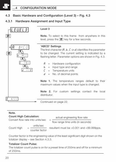
LEVEL3
b 1KC0
A 1KC0
C 1KC0
d 1KC0
E 1203
…4 CONFIGURATION MODE
Level 3
Note. To select to this frame from anywhere in thislevel, press the key for a few seconds.
'ABCD' SettingsThe first character (A, b, C or d) identifies the parameterto be changed. The current setting is indicated by aflashing letter. Parameter options are shown in Fig. 4.3.
A = Hardware configurationb = Input type and rangeC = Temperature unitsd = No. of decimal points
Note 1. The temperature ranges default to theirmaximum values when the input type is changed.
Note 2. For custom settings contact the localdistributor.
Continued on page 22.
4.3 Basic Hardware and Configuration (Level 3) – Fig. 4.3
4.3.1 Hardware Assignment and Input Type
Note.Count High Calculation:Convert flow rate into units/sec =
actual engineering flow rate
flow range time units (in seconds)
Count High = units/sec
counter factorresultant must be >0.001 and <99.999pps.
Counter factor is the engineering value of the least significant digit shown on thetotalizer display – see Section 4.3.3.
Totalizer Count Pulse:The totalizer count pulse is on for a preset time of 250ms and off for a minimumof 250ms.
21
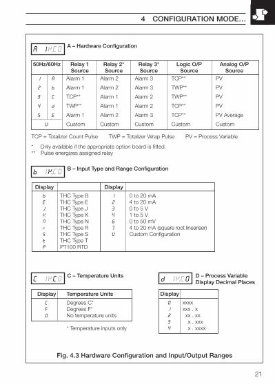
50Hz/60Hz Relay 1 Relay 2* Relay 3* Logic O/P Analog O/PSource Source Source Source Source
1 A Alarm 1 Alarm 2 Alarm 3 TCP** PV
2 b Alarm 1 Alarm 2 Alarm 3 TWP** PV
3 C TCP** Alarm 1 Alarm 2 TWP** PV
4 d TWP** Alarm 1 Alarm 2 TCP** PV
5 E Alarm 1 Alarm 2 Alarm 3 TCP** PV Average
U Custom Custom Custom Custom Custom
A 1KC0A – Hardware Configuration
TCP = Totalizer Count Pulse TWP = Totalizer Wrap Pulse PV = Process Variable
b 1KC0B – Input Type and Range Configuration
C 1KC0D – Process VariableDisplay Decimal Places
Display
0 xxxx1 xxx . x2 xx . xx3 x . xxx4 x . xxxx
d 1KC0C – Temperature Units
Display Temperature Units
C Degrees C*F Degrees F*0 No temperature units
* Temperature inputs only
Display
b THC Type BE THC Type EJ THC Type JK THC Type KN THC Type Nr THC Type RS THC Type St THC Type TP PT100 RTD
Display
1 0 to 20 mA2 4 to 20 mA3 0 to 5 V4 1 to 5 V6 0 to 50 mV7 4 to 20 mA (square root lineariser)U Custom Configuration
* Only available if the appropriate option board is fitted.** Pulse energizes assigned relay
4 CONFIGURATION MODE…
Fig. 4.3 Hardware Configuration and Input/Output Ranges
22
Trip point
Alarm on
Alarm off
Alarm on
Alarm off
High Process
Low Process
Hysteresis
Hysteresis
ProcessVariable
F 0000
E 0000
G 0000
H 0000
J 0000
…4 CONFIGURATION MODE
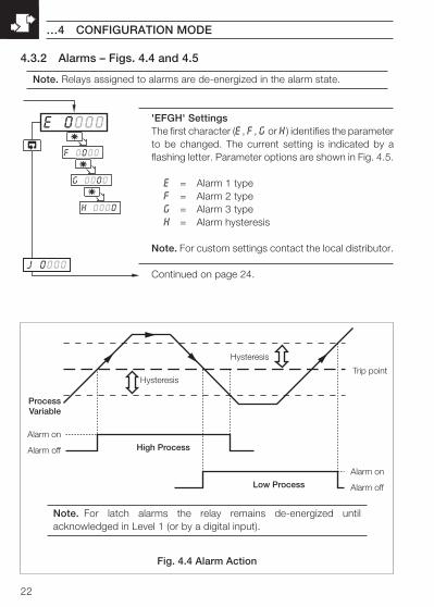
'EFGH' SettingsThe first character (E, F, G or H) identifies the parameterto be changed. The current setting is indicated by aflashing letter. Parameter options are shown in Fig. 4.5.
E = Alarm 1 typeF = Alarm 2 typeG = Alarm 3 typeH = Alarm hysteresis
Note. For custom settings contact the local distributor.
Continued on page 24.
Fig. 4.4 Alarm Action
Note. For latch alarms the relay remains de-energized untilacknowledged in Level 1 (or by a digital input).
4.3.2 Alarms – Figs. 4.4 and 4.5
Note. Relays assigned to alarms are de-energized in the alarm state.
23
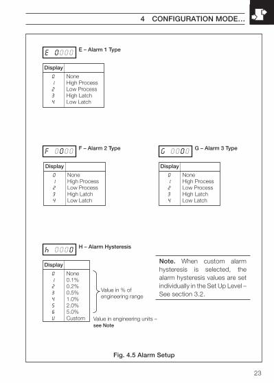
E 0000
F 0000 G 0000
h 0000
Display
0 None1 0.1%2 0.2%3 0.5%4 1.0%5 2.0%6 5.0%U Custom
H – Alarm Hysteresis
G – Alarm 3 Type
Display
0 None1 High Process2 Low Process3 High Latch4 Low Latch
E – Alarm 1 Type
Display
0 None1 High Process2 Low Process3 High Latch4 Low Latch
F – Alarm 2 Type
Display
0 None1 High Process2 Low Process3 High Latch4 Low Latch
Value in % ofengineering range
Value in engineering units –see Note
4 CONFIGURATION MODE…
Note. When custom alarmhysteresis is selected, thealarm hysteresis values are setindividually in the Set Up Level –See section 3.2.
Fig. 4.5 Alarm Setup
24
K 0000
J 0000
L 0000
n 0000
P 0000
…4 CONFIGURATION MODE
4.3.3 Operator Functions and Totalizer Set Up – Fig. 4.6
'JKLN' SettingsThe first character (J, K, L or n) identifies the parameterto be changed. The current setting is indicated by aflashing letter. Parameter options are shown in Fig. 4.6.
J = Totalizer set-upK = No. of decimal places for totalizerL = Operator level frame enablen = Operator level functions enable/disable
Note. For custom settings contact the local distributor.
Continued on page 26.
25
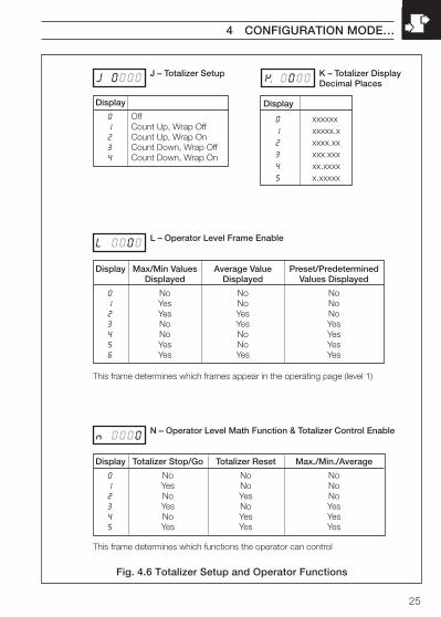
J 0000 K 0000
L 0000
n 0000
Display Max/Min Values Average Value Preset/PredeterminedDisplayed Displayed Values Displayed
0 No No No1 Yes No No2 Yes Yes No3 No Yes Yes4 No No Yes5 Yes No Yes6 Yes Yes Yes
L – Operator Level Frame Enable
Display Totalizer Stop/Go Totalizer Reset Max./Min./Average
0 No No No1 Yes No No2 No Yes No3 Yes No Yes4 No Yes Yes5 Yes Yes Yes
N – Operator Level Math Function & Totalizer Control Enable
This frame determines which frames appear in the operating page (level 1)
This frame determines which functions the operator can control
J – Totalizer Setup
Display
0 Off1 Count Up, Wrap Off2 Count Up, Wrap On3 Count Down, Wrap Off4 Count Down, Wrap On
K – Totalizer DisplayDecimal Places
Display
0 xxxxxx1 xxxxx.x2 xxxx.xx3 xxx.xxx4 xx.xxxx5 x.xxxxx
4 CONFIGURATION MODE…
Fig. 4.6 Totalizer Setup and Operator Functions
26
Max
Min
Stop
Go
Reset Lock
Unlock
Acknowledge
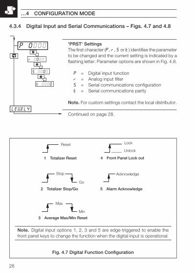
1 Totalizer Reset
2 Totalizer Stop/Go
3 Average Max/Min Reset
4 Front Panel Lock out
5 Alarm Acknowledge
r 0000
P 0000
S 0000
t 0000
LEVEL4
…4 CONFIGURATION MODE
4.3.4 Digital Input and Serial Communications – Figs. 4.7 and 4.8
Fig. 4.7 Digital Function Configuration
Note. Digital input options 1, 2, 3 and 5 are edge-triggered to enable thefront panel keys to change the function when the digital input is operational.
'PRST' SettingsThe first character (P, r, S or t) identifies the parameterto be changed and the current setting is indicated by aflashing letter. Parameter options are shown in Fig. 4.8.
P = Digital input functionr = Analog input filterS = Serial communications configurationt = Serial communications parity
Note. For custom settings contact the local distributor.
Continued on page 28.
27
P 0000 r 0000
S 0000 t 0000
Display Baud Rate, 2/4 Wire
0 Off1 2400, 2 Wire2 2400, 4 Wire3 9600, 2 Wire4 9600, 4 Wire
S – Serial CommunicationConfiguration
Display
0 None1 Odd2 Even
T – Serial CommunicationParity
Display
0 None1 Totalizer Reset2 Totalizer Stop/Go3 Average, Max/Min Reset4 Front Panel Lockout5 Alarm Acknowledge
P – Digital Input Function
Display
0 0 seconds1 1 second2 2 seconds5 5 secondsA 10 secondsb 20 secondsC 40 secondsd 60 seconds
R – Analog Input Filter
4 CONFIGURATION MODE…
Fig. 4.8 Digital Function and Serial Communications Configuration
Note. Settings for options P, S and T are availableonly if the appropriate option board is fitted.
28
0.0
ENG HI
100.0
ENG LO
LEVEL4
CNt HI
•1
•1
…4 CONFIGURATION MODE
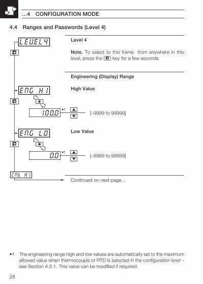
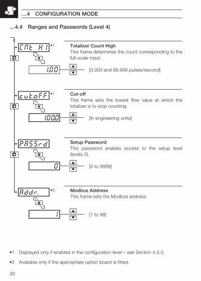
4.4 Ranges and Passwords (Level 4)
•1 The engineering range high and low values are automatically set to the maximumallowed value when thermocouple or RTD is selected in the configuration level –see Section 4.3.1. This value can be modified if required.
Level 4
Note. To select to this frame from anywhere in thislevel, press the key for a few seconds.
Engineering (Display) Range
High Value
[–9999 to 99999]
Low Value
[–9999 to 99999]
Continued on next page…
29
100.0
rEt HI
100.0
rEt LO
CNt HI
•1
•1
4 CONFIGURATION MODE…
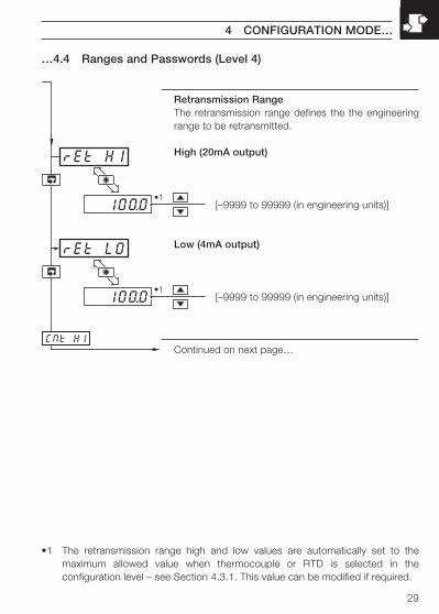
…4.4 Ranges and Passwords (Level 4)
Retransmission RangeThe retransmission range defines the the engineeringrange to be retransmitted.
High (20mA output)
[–9999 to 99999 (in engineering units)]
Low (4mA output)
[–9999 to 99999 (in engineering units)]
Continued on next page…
•1 The retransmission range high and low values are automatically set to themaximum allowed value when thermocouple or RTD is selected in theconfiguration level – see Section 4.3.1. This value can be modified if required.
30
100.0
CNt HI
1.00
cut.oFF
0
PASSrd
1
Addr.
•1
•1
•2
…4.4 Ranges and Passwords (Level 4)
Totalizer Count HighThis frame determines the count corresponding to thefull-scale input.
[0.000 and 99.999 pulses/second]
Cut-offThis frame sets the lowest flow value at which thetotalizer is to stop counting.
[In engineering units]
Setup PasswordThis password enables access to the setup level(levels 2).
[0 to 9999]
Modbus AddressThis frame sets the Modbus address.
[1 to 99]
•1 Displayed only if enabled in the configuration level – see Section 4.3.3.
•2 Available only if the appropriate option board is fitted.
…4 CONFIGURATION MODE

31
EC Directive 89/336/EECIn order to meet the requirements of the EC Directive 89/336/EEC for EMCregulations, this product must not be used in a non-industrial environment.
End of Life DisposalThis instrument does not contain any substance that will cause undue harm tothe environment. It can therefore be safely considered as normal waste anddisposed of accordingly.
CleaningClean the front panel only, using warm water and a mild detergent.
5 INSTALLATION
32
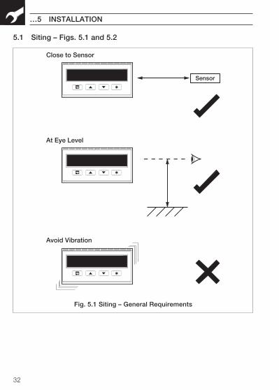
Sensor
Close to Sensor
Avoid Vibration
At Eye Level
…5 INSTALLATION
5.1 Siting – Figs. 5.1 and 5.2
Fig. 5.1 Siting – General Requirements
33
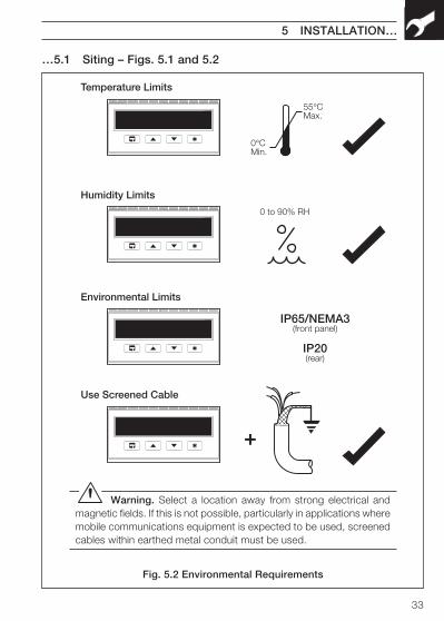
Temperature Limits
55°CMax.
0°CMin.
0 to 90% RH
Humidity Limits
IP65/NEMA3(front panel)
IP20(rear)
Environmental Limits
Use Screened Cable
+
5 INSTALLATION…
Fig. 5.2 Environmental Requirements
…5.1 Siting – Figs. 5.1 and 5.2
Warning. Select a location away from strong electrical andmagnetic fields. If this is not possible, particularly in applications wheremobile communications equipment is expected to be used, screenedcables within earthed metal conduit must be used.
34
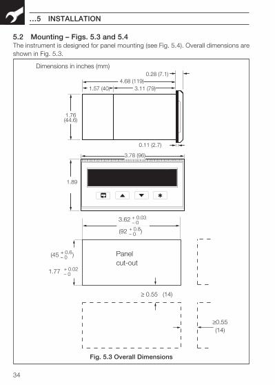
3.62
Dimensions in inches (mm)
4.68 (119)1.57 (40) 3.11 (79)
1.76(44.6)
0.11 (2.7)
0.28 (7.1)
3.78 (96)
1.89
Panelcut-out
+ 0.03– 0
(92 )+ 0.8– 0
(45 )+ 0.6– 0
1.77 + 0.02– 0
≥0.55(14)
≥ 0.55 (14)
…5 INSTALLATION
Fig. 5.3 Overall Dimensions
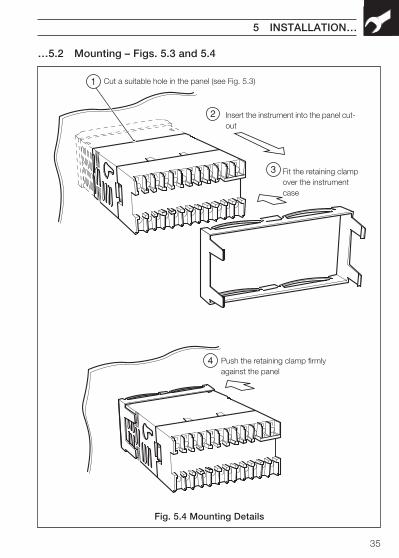
5.2 Mounting – Figs. 5.3 and 5.4The instrument is designed for panel mounting (see Fig. 5.4). Overall dimensions areshown in Fig. 5.3.
35
Cut a suitable hole in the panel (see Fig. 5.3)
Insert the instrument into the panel cut-out
Fit the retaining clampover the instrumentcase
Push the retaining clamp firmlyagainst the panel
1
2
3
4
5 INSTALLATION…
Fig. 5.4 Mounting Details
…5.2 Mounting – Figs. 5.3 and 5.4
36
…5 INSTALLATION
5.3 Electrical Connections – Fig. 5.5
Warning.• The instrument is not fitted with a switch therefore a disconnecting device
such as a switch or circuit breaker conforming to local safety standards mustbe fitted to the final installation. It must be mounted in close proximity to theinstrument within easy reach of the operator and must be marked clearly asthe disconnection device for the instrument
• Remove all power from supply, relay and any powered control circuits andhigh common mode voltages before accessing or making any connections.
• Use cable appropriate for the load currents. The terminals accept cables upto 14AWG (2.5mm2).
• The instrument conforms to Mains Power Input Insulation Category 2,Pollution Degree 2 (EN601010–1).
• All connections to secondary circuits must have basic insulation.
• After installation, there must be no access to live parts, e.g. terminals
• Terminals for external circuits are for use only with equipment with noaccessible live parts.
• If the instrument is used in a manner not specified by the Company, theprotection provided by the equipment may be impaired.
• All equipment connected to the instrument's terminals must comply withlocal safety standards (IEC 60950, EN601010–1).
Note.• Always route signal leads and power cables separately, preferably in earthed
(grounded) metal conduit.
• It is strongly recommended that screened cable is used for signal inputs andrelay connections.
This equipment is protected through double insulation (Class II).
37
5 INSTALLATION…
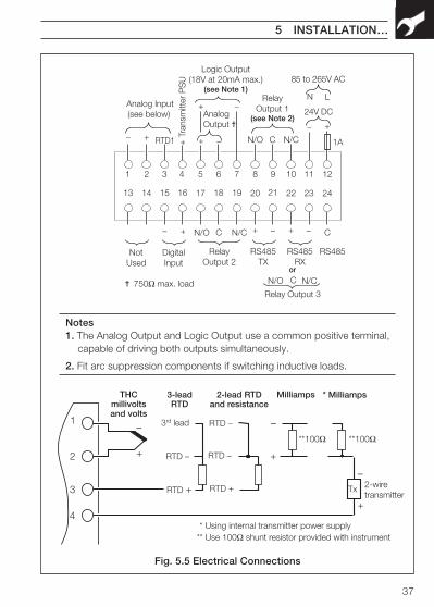
Fig. 5.5 Electrical Connections
AnalogOutput
85 to 265V AC
C
RelayOutput 1
(see Note 2)
1 2 3 4 5 6 7 8 9 10 11 12
13 14 15 16 17 18 19 20 21 22 23 24
–
+– N/CCN/O
RelayOutput 2
N/CCN/O
DigitalInput
+ –
RS485TX
RS485RX
+
RS485
or
Relay Output 3
N/CCN/O
+ + –
– Analog Input(see below)
RTD1
Tran
smitt
er P
SU
+
+
Logic Output(18V at 20mA max.)
(see Note 1)
–
NotUsed
750Ω max. load
24V DC
+–
LN
1A
–
+
THCmillivoltsand volts
RTD –
3rd lead
RTD +
3-leadRTD
–
+
Milliamps
1
2
3
4
–
+
* Milliamps
2-wiretransmitter
RTD –
RTD –
RTD +
2-lead RTDand resistance
**100Ω
* Using internal transmitter power supply
**100Ω
Tx
** Use 100Ω shunt resistor provided with instrument
Notes1. The Analog Output and Logic Output use a common positive terminal,
capable of driving both outputs simultaneously.
2. Fit arc suppression components if switching inductive loads.
38
5.4 Relays, Arc Suppression, Inputs and Outputs
5.4.1 Relay Contact RatingsRelay contacts are rated at:
115/230V AC at 5A (non-inductive)
250V DC 25W max.
5.4.2 Arc SuppressionArc suppression components are fitted to relays 2 and 3 only. If relay 1 is required toswitch inductive loads, fit the arc suppression components supplied.
5.4.3 Logic Output18V DC at 20mA
Min load 900Ω
Isolated from Analog Input (not isolated from Retransmission O/P).
Dielectric strength: 500V d.c. for 1 minute.
5.4.4 RetransmissionAnalog Output
Max. load 15V (750Ω at 20mA)
Isolated from Analog Input (not isolated from Logic O/P).
Dielectric strength: 500V d.c. for 1 minute.
5.4.5 Digital InputType: Volt-free
Minimum Pulse: 250 ms
…5 INSTALLATION
39
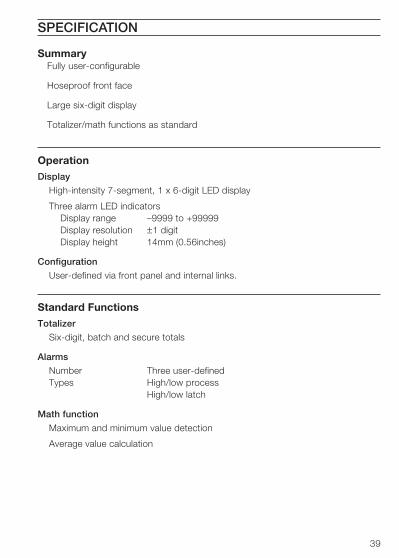
SummaryFully user-configurable
Hoseproof front face
Large six-digit display
Totalizer/math functions as standard
OperationDisplay
High-intensity 7-segment, 1 x 6-digit LED display
Three alarm LED indicatorsDisplay range –9999 to +99999Display resolution ±1 digitDisplay height 14mm (0.56inches)
Configuration
User-defined via front panel and internal links.
Standard FunctionsTotalizer
Six-digit, batch and secure totals
Alarms
Number Three user-definedTypes High/low process
High/low latch
Math function
Maximum and minimum value detection
Average value calculation
SPECIFICATION
40
…SPECIFICATION
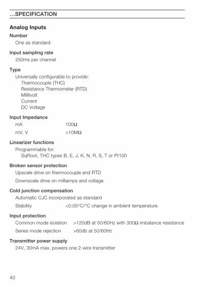
Analog InputsNumber
One as standard
Input sampling rate
250ms per channel
Type
Universally configurable to provide:Thermocouple (THC)Resistance Thermometer (RTD)MilllivoltCurrentDC Voltage
Input Impedance
mA 100Ω
mV, V >10MΩ
Linearizer functions
Programmable for:SqRoot, THC types B, E, J, K, N, R, S, T or Pt100
Broken sensor protection
Upscale drive on thermocouple and RTD
Downscale drive on milliamps and voltage
Cold junction compensation
Automatic CJC incorporated as standard
Stability <0.05°C/°C change in ambient temperature
Input protection
Common mode isolation >120dB at 50/60Hz with 300Ω imbalance resistance
Series mode rejection >60db at 50/60Hz
Transmitter power supply
24V, 30mA max. powers one 2-wire transmitter
41
SPECIFICATION…
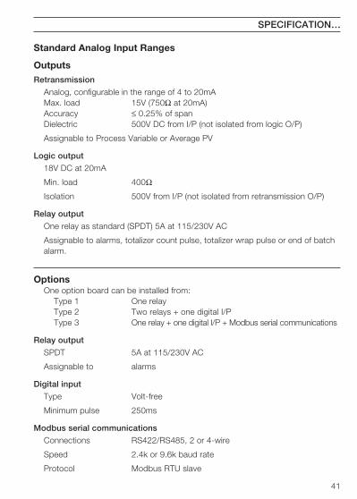
Standard Analog Input Ranges
OutputsRetransmission
Analog, configurable in the range of 4 to 20mAMax. load 15V (750Ω at 20mA)Accuracy ≤ 0.25% of spanDielectric 500V DC from I/P (not isolated from logic O/P)
Assignable to Process Variable or Average PV
Logic output
18V DC at 20mA
Min. load 400Ω
Isolation 500V from I/P (not isolated from retransmission O/P)
Relay output
One relay as standard (SPDT) 5A at 115/230V AC
Assignable to alarms, totalizer count pulse, totalizer wrap pulse or end of batchalarm.
OptionsOne option board can be installed from:
Type 1 One relayType 2 Two relays + one digital I/PType 3 One relay + one digital I/P + Modbus serial communications
Relay output
SPDT 5A at 115/230V AC
Assignable to alarms
Digital input
Type Volt-free
Minimum pulse 250ms
Modbus serial communications
Connections RS422/RS485, 2 or 4-wire
Speed 2.4k or 9.6k baud rate
Protocol Modbus RTU slave
42
…SPECIFICATION
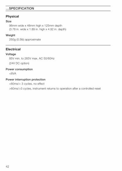
PhysicalSize
96mm wide x 48mm high x 125mm depth(3.78 in. wide x 1.89 in. high x 4.92 in. depth)
Weight
250g (0.5lb) approximate
ElectricalVoltage
85V min. to 265V max. AC 50/60Hz
(24V DC option)
Power consumption
<6VA
Power interruption protection
<60ms/< 3 cycles, no effect
>60ms/>3 cycles, instrument returns to operation after a controlled reset

43
EnvironmentalOperating limits
0 to 55°C (32 to 131°F)
5 to 95% RH non-condensing
Temperature stability
< 0.02% of reading or 2µV/°C (1µV/°F)
Front face
IP65 (NEMA3), case rear IP20
EMCEmissions
Meets requirements of EN50081-2
Immunity
Meets requirements of EN50082-2
Design and manufacturing standards
CE mark
Safety standards
EN61010 – 1
C22.2 No. 1010
UL 310 – 1
FM 3810
SS/C150 Issue 9
SPECIFICATION

44
NOTES
8CUSTOMER SETUP LOGCustomer SupportWe provide a comprehensive after salesservice via our Worldwide ServiceOrganization. Contact one of the followingoffices for details on your nearest Serviceand Repair Centre.
United KingdomABB LimitedTel: +44 (0)1480 475321Fax: +44 (0)1480 217948
United States of AmericaABB Inc.Tel: +1 215-674-6000Fax: +1 215-674-7183
Client Warranty
Prior to installation, the equipment referred to in this manual must be stored in a clean,dry environment, in accordance with the Company's published specification. Periodicchecks must be made on the equipment's condition.
In the event of a failure under warranty, the following documentation must be providedas substantiation:
1. A listing evidencing process operation and alarm logs at time of failure.
2. Copies of all operating and maintenance records relating to the alleged faulty unit.
LEVEL1
LEVEL2
A1xx
A2xx
A3xx
xxxxxx
t-GO
SEC.tot
PrESEt
PrEdEt
A xxxx
H xxxx
CodE
L xxxx
0AdJ
Instrument Serial Number:
Product Code: C 1 5 0 / /
IM/C
150
Issu
e 13
The Company’s policy is one of continuous productimprovement and the right is reserved to modify the
information contained herein without notice.
Printed in UK (07.05)
© ABB 2005
ABB LimitedHoward Road, St. NeotsCambridegshirePE19 8EUUKTel: +44 (0)1480 475321Fax:+44 (0)1480 217948
ABB Inc125 E. County Line RoadWarminsterPA 18974USATel: +1 215 674 6000Fax:+1 215-674 7183
ABB has Sales & Customer Support expertisein over 100 countries worldwide
www.abb.com
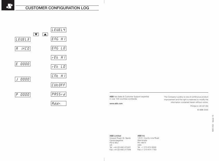
CUSTOMER CONFIGURATION LOG
E 0000
LEVEL3
LEVEL4
ENG HI
ENG LO
rEt HI
rEt LO
A 1KC0
J 0000
P 0000
CNt HI
CUtOFF
PASSrd
Addr.
A B C D
E F G H
J K L N
P R S T